WO2012111773A1 - Pneumatic tire - Google Patents
Pneumatic tire Download PDFInfo
- Publication number
- WO2012111773A1 WO2012111773A1 PCT/JP2012/053708 JP2012053708W WO2012111773A1 WO 2012111773 A1 WO2012111773 A1 WO 2012111773A1 JP 2012053708 W JP2012053708 W JP 2012053708W WO 2012111773 A1 WO2012111773 A1 WO 2012111773A1
- Authority
- WO
- WIPO (PCT)
- Prior art keywords
- tire
- region
- smooth surface
- pneumatic tire
- ridge
- Prior art date
Links
Images


Classifications
-
- B—PERFORMING OPERATIONS; TRANSPORTING
- B29—WORKING OF PLASTICS; WORKING OF SUBSTANCES IN A PLASTIC STATE IN GENERAL
- B29D—PRODUCING PARTICULAR ARTICLES FROM PLASTICS OR FROM SUBSTANCES IN A PLASTIC STATE
- B29D30/00—Producing pneumatic or solid tyres or parts thereof
- B29D30/06—Pneumatic tyres or parts thereof (e.g. produced by casting, moulding, compression moulding, injection moulding, centrifugal casting)
- B29D30/72—Side-walls
-
- B—PERFORMING OPERATIONS; TRANSPORTING
- B60—VEHICLES IN GENERAL
- B60C—VEHICLE TYRES; TYRE INFLATION; TYRE CHANGING; CONNECTING VALVES TO INFLATABLE ELASTIC BODIES IN GENERAL; DEVICES OR ARRANGEMENTS RELATED TO TYRES
- B60C13/00—Tyre sidewalls; Protecting, decorating, marking, or the like, thereof
- B60C13/001—Decorating, marking or the like
-
- B—PERFORMING OPERATIONS; TRANSPORTING
- B29—WORKING OF PLASTICS; WORKING OF SUBSTANCES IN A PLASTIC STATE IN GENERAL
- B29D—PRODUCING PARTICULAR ARTICLES FROM PLASTICS OR FROM SUBSTANCES IN A PLASTIC STATE
- B29D30/00—Producing pneumatic or solid tyres or parts thereof
- B29D30/06—Pneumatic tyres or parts thereof (e.g. produced by casting, moulding, compression moulding, injection moulding, centrifugal casting)
- B29D30/0601—Vulcanising tyres; Vulcanising presses for tyres
- B29D30/0606—Vulcanising moulds not integral with vulcanising presses
- B29D2030/0607—Constructional features of the moulds
- B29D2030/0618—Annular elements, e.g. rings, for moulding the tyre shoulder areas
-
- B—PERFORMING OPERATIONS; TRANSPORTING
- B29—WORKING OF PLASTICS; WORKING OF SUBSTANCES IN A PLASTIC STATE IN GENERAL
- B29D—PRODUCING PARTICULAR ARTICLES FROM PLASTICS OR FROM SUBSTANCES IN A PLASTIC STATE
- B29D30/00—Producing pneumatic or solid tyres or parts thereof
- B29D30/06—Pneumatic tyres or parts thereof (e.g. produced by casting, moulding, compression moulding, injection moulding, centrifugal casting)
- B29D30/72—Side-walls
- B29D2030/726—Decorating or marking the sidewalls before tyre vulcanization
Definitions
- the present invention relates to a pneumatic tire.
- the mark arranged on the tire side portion indicates the mark itself, and there is still room for improvement in order to improve the uniqueness of the product.
- the present invention has an object to improve the uniqueness of a product by a pattern arranged on the tire side portion in consideration of the above facts.
- the first aspect (pneumatic tire) of the present invention includes a decorative portion provided on a tire side portion, and one or more portions provided on the decorative portion separately from a mark, and a character using a ridge region and a smooth surface region.
- the symbol has a patterned pattern.
- the pattern formed by patterning characters or symbols using the ridge region and the smooth surface region is provided in the decorative portion of the tire side portion, and the ridge region and the smooth surface region Since the surface roughness is different, the visibility of characters or symbols is improved. Since this pattern is provided separately from the mark, the uniqueness of the product can be further improved.
- a second aspect of the present invention is the pneumatic tire according to the first aspect, wherein the character or the symbol is repeatedly arranged in at least one of the tire radial direction and the tire circumferential direction.
- the visibility of characters or symbols can be further improved.
- the number of repetitions is preferably 4 or more.
- the smooth surface region is continuously in the tire radial direction so as to divide the ridge region in the tire circumferential direction. It is formed.
- the smooth surface region in the pattern is formed continuously in the tire radial direction and the ridge region is divided in the tire circumferential direction, the tire circumferential direction component of the smooth surface region The edge of the smooth surface region is less likely to be a core of side cracks. For this reason, the side crack durability in the tire circumferential direction can be improved.
- the ridge region and the smooth surface region can be read as the character or the symbol, respectively.
- the uniqueness of the product is more than the configuration in which only one of the ridge region and the smooth surface region can be read. Can be improved.
- the character or the symbol is the same as an initial of an applicable product name.
- the character or symbol is the same as the initial letter of the applicable product name and is related to the applicable product name, so that the uniqueness of the product can be appealed from the appearance. .
- a ridge region is formed in a portion for molding a decorative portion of a tire side portion of a mold for tire molding, and a part of the ridge region is formed.
- a smooth surface region that is continuous in the tire radial direction so that a part of the ridge region of the mold is removed and the ridge region is divided in the tire circumferential direction. Since the characters or symbols are patterned by forming the mold, the mold can be easily manufactured. Further, by using the mold for the production of a pneumatic tire, a pneumatic tire having a high product uniqueness can be produced.
- the uniqueness of the product can be improved by the pattern arranged on the tire side portion.
- the pneumatic tire according to the fourth aspect it is possible to obtain an excellent effect that the uniqueness of the product can be improved as compared with the configuration in which only one of the ridge region and the smooth surface region can be read.
- the pneumatic tire according to the fifth aspect it is possible to obtain an excellent effect that the uniqueness of the product can be appealed from the appearance.
- an excellent effect is obtained that a mold can be easily manufactured and a pneumatic tire having a high product characteristic can be manufactured. It is done.
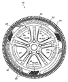
- a pneumatic tire 10 according to the present embodiment has a decorative portion 12 and a pattern 14 and is attached to a rim 16.
- the decorative portion 12 is provided on the tire side portion 18 in a belt shape, for example, along the tire circumferential direction, and has a ridge region 20.
- the decorative portion 12 is divided into, for example, a plurality of decorative elements 21 to 29 arranged in series clockwise in FIG.
- the decorative elements 21, 24, 27 are configured to be long in the tire circumferential direction, and the decorative elements 22, 23, 25, 26, 28, 29 are configured to be shorter in the tire circumferential direction than the decorative elements 21, 24, 27. Yes.
- the decorative elements 22 and 23 are arranged between the decorative elements 21 and 24.
- the decorative elements 25 and 26 are arranged between the decorative elements 24 and 27.
- the decorative elements 28 and 29 are arranged between the decorative elements 21 and 27.
- the decorative elements 21, 23, 24, 26, 27, 29 (elements other than the decorative elements 22, 25, 28) in the decorative portion 12 are mainly constituted by the ridge region 20.
- a mark 32 of “TURANZA”, which is an example of an applicable product name of the pneumatic tire 10 is displayed using the smooth surface region 30.
- a mark 34 of “BRIDGESTONE” indicating the manufacturer is displayed on the inner side of the decorative element 27 using the smooth surface region 30 in the same manner.
- other marks, tire sizes, and the like can be displayed on the tire side portion 18.
- the mark 32 is a part where readability is more important than design.
- the decoration part 12 originally gives only an aesthetics, in this embodiment, the uniqueness and image of goods are strongly given to a consumer.
- one or more patterns 14 are provided on the decorative portion 12 separately from the mark 32.
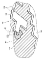
- the patterns 14 are provided at a total of three locations, for example, the decorative elements 22, 25, and 28 in the decorative portion 12. Both ends of the pattern 14 in the tire circumferential direction are inclined with respect to the tire radial direction.
- characters or symbols 36 are patterned using the ridge region 20 and the smooth surface region 30. This character or symbol 36 is the same as the initial letter “T” of the mark 32 of “TURANZA”, which is an applicable product name.
- “same” does not require that the font or size is the same, but may be anything that can read the initial letter “T”.
- the characters or symbols 36 are displayed on both the ridge region 20 and the smooth surface region 30, and the ridge region 20 and the smooth surface region 30 can be read as the characters or symbols 36, respectively.
- Two or more characters or symbols 36 are repeatedly arranged in at least one of the tire radial direction and the tire circumferential direction. The number of repetitions is preferably 4 or more. In the present embodiment, the characters or symbols 36 are repeatedly arranged about 4 times in the tire radial direction and about 10 times in the tire circumferential direction.
- the ridge region 20 and the smooth surface region 30 are upside down.
- the smooth surface region 30 is continuously formed in the tire radial direction so as to divide the ridge region 20 in the tire circumferential direction.
- the ridge region 20 is also formed continuously in the tire radial direction so as to divide the smooth surface region 30 in the tire circumferential direction. That is, in the pattern 14, the ridge region 20 and the smooth surface region 30 are formed continuously in the tire radial direction and are alternately arranged in the tire circumferential direction.
- the “tire radial direction” includes a direction slightly inclined with respect to the tire radial direction.
- the character or symbol 36 is the same as the initial letter “T” of the mark 32 of “TURANZA”, which is the applicable product name, and is associated with the applicable product name. You can appeal from the appearance. Furthermore, since two or more characters or symbols 36 are repeatedly arranged in at least one of the tire radial direction and the tire circumferential direction, the visibility of the characters or symbols 36 is further improved.
- the ridge region 20 and the smooth surface region 30 can be read as characters or symbols 36, respectively, the uniqueness of the product can be improved as compared with the configuration in which only one of the ridge region 20 and the smooth surface region 30 can be read. it can.
- the smooth surface region 30 in the pattern 14 is formed continuously in the tire radial direction, and the ridge region 20 is divided in the tire circumferential direction, so the tire circumferential direction of the smooth surface region 30 is There are few components and the edge part of this smooth surface area
- region 30 does not become easily the nucleus of a side crack. For this reason, the side crack durability in the tire circumferential direction can be improved.
- the width of the vertical bar portion of the letter “T” in the tire circumferential direction is a, and the tire where the letter “T” continues in the tire radial direction
- the width in the circumferential direction is b
- the offset amount in the horizontal bar direction of the letter “T” at the same part is c.
- the width in the tire circumferential direction of the portion where the letter “T” continues in the tire radial direction is defined as d.
- the difference between the width a and the width b is large. Further, in the letter “T” that is continuous in the tire radial direction, a portion having a width b is a constricted portion. Thereby, while improving the independence of each character, generation
- the width b in the ridge region 20 is equal to the width d in the smooth surface region 30.
- the ridge region 20 is located lower than the smooth surface region 30. Therefore, in the tire molding die for molding the decorative element 28, it is necessary to cut a portion corresponding to the smooth surface region 30 deeper than a portion corresponding to the ridge region 20. At that time, by making the width b in the ridge region 20 and the width d in the smooth surface region 30 equal, the tool diameters used for the die processing can be made uniform, and the manufacture becomes easy.
- both the ridge region 20 and the smooth surface region 30 are visible as the letter “T” or symbol 36, respectively.
- the configurations of the decorative elements 21 to 29 in the decorative portion 12 are not limited to those described and illustrated above.
- the character or symbol 36 is the same as the initial letter “T” of the mark 32 of “TURANZA” which is an applicable product name, the present invention is not limited to this, for example, the mark 34 of “BRIDGESTONE” indicating the manufacturer.
- the initial letter “B” or other letters or symbols may be used.
- the smooth surface region 30 is formed continuously in the tire radial direction so as to divide the ridge region 20 in the tire circumferential direction.
- the present invention is not limited to this.
- the smooth surface region 30 is formed in the ridge region 20. It may be scattered.
- the ridge region 20 and the smooth surface region 30 are readable as characters or symbols 36, respectively.
- the ridge region 20 and the smooth surface region 30 can be read as characters or symbols 36.
- the region 20 may be configured so as not to be readable as the character or symbol 36.
- the manufacturing method of the pneumatic tire according to the present embodiment forms a ridge region 120 in a portion of the tire molding die 40 where the decorative portion 14 (FIG. 1) of the tire side portion is molded, A part of the ridge region 120 is removed to form a smooth surface region 130 that continues in a direction corresponding to the tire radial direction so that the ridge region 120 is divided in the tire circumferential direction. 136 is patterned and a pneumatic tire is molded using the mold 40.
- a part of the ridge area 120 of the mold 40 is removed to form the smooth surface area 130, whereby the characters or symbols 136 are patterned.
- a part of the ridge region 120 is cut using a tool 42 such as an end mill.
- the diameter of the tool 42 correspond to the width d (FIG. 3)
- the letter “T” or the symbol 136 can be continuously formed in the direction corresponding to the tire radial direction.
- the machining time can be shortened as compared with the case where the letter “T” or the symbol 136 is independent.
- the process for removing a part of the ridge region 120 is not limited to cutting, and electric discharge machining or the like can also be used.
- the ridge region 120 (FIG. 3) of the pattern 14 can be molded by the ridge region 120 of the mold 40, and the smooth surface region 30 (FIG. 3) of the pattern 14 can be molded by the smooth surface region 130 of the mold 40.
Landscapes
- Engineering & Computer Science (AREA)
- Mechanical Engineering (AREA)
- Moulds For Moulding Plastics Or The Like (AREA)
- Tires In General (AREA)
Abstract
The purpose of the present invention is to improve characteristic properties of a product by means of a design on a tire side. A pneumatic tire (10) comprises: a decorative part (12) formed on a tire side portion (18); and a design (14) formed in at least one region of the decorative part (12) separately from emblems (32), (34) by patterning a ridge region (20) and a smooth surface region (30) with letters or symbols (36).
Description
本発明は、空気入りタイヤに関する。
The present invention relates to a pneumatic tire.
サイドウォール部にリッジを有する環状帯を設け、該環状帯の一部に平滑面による標章等の模様を配置した空気入りタイヤが開示されている(特許文献1参照)。
There has been disclosed a pneumatic tire in which an annular belt having a ridge is provided in a sidewall portion, and a pattern such as a mark with a smooth surface is arranged on a part of the annular belt (see Patent Document 1).
しかしながら、上記した従来例のように、タイヤサイド部に配置された標章は、その標章自体を示すものであって、商品の固有性を向上させるには、未だ改善の余地がある。
However, as in the conventional example described above, the mark arranged on the tire side portion indicates the mark itself, and there is still room for improvement in order to improve the uniqueness of the product.
本発明は、上記事実を考慮して、タイヤサイド部に配置する模様により、商品の固有性を向上させることを目的とする。
The present invention has an object to improve the uniqueness of a product by a pattern arranged on the tire side portion in consideration of the above facts.
本発明の第1の態様(空気入りタイヤ)は、タイヤサイド部に設けられる装飾部と、該装飾部に、標章とは別に1箇所以上設けられ、リッジ領域及び平滑面領域を用いて文字又は記号がパターン化された模様と、を有している。
The first aspect (pneumatic tire) of the present invention includes a decorative portion provided on a tire side portion, and one or more portions provided on the decorative portion separately from a mark, and a character using a ridge region and a smooth surface region. Alternatively, the symbol has a patterned pattern.
第1の態様に係る空気入りタイヤでは、リッジ領域及び平滑面領域を用いて文字又は記号がパターン化されてなる模様が、タイヤサイド部の装飾部に設けられており、リッジ領域と平滑面領域とにおいて表面粗さが異なるため、文字又は記号の視認性が向上する。この模様は、標章とは別に設けられているので、商品の固有性を更に向上させることができる。
In the pneumatic tire according to the first aspect, the pattern formed by patterning characters or symbols using the ridge region and the smooth surface region is provided in the decorative portion of the tire side portion, and the ridge region and the smooth surface region Since the surface roughness is different, the visibility of characters or symbols is improved. Since this pattern is provided separately from the mark, the uniqueness of the product can be further improved.
本発明の第2の態様は、第1の態様に係る空気入りタイヤにおいて、前記文字又は前記記号は、タイヤ径方向及びタイヤ周方向の少なくとも一方に、2つ以上繰り返し配置される。
A second aspect of the present invention is the pneumatic tire according to the first aspect, wherein the character or the symbol is repeatedly arranged in at least one of the tire radial direction and the tire circumferential direction.
第2の態様に係る空気入りタイヤでは、文字又は記号の視認性を更に向上させることができる。繰返し数は、4回以上であることが望ましい。
In the pneumatic tire according to the second aspect, the visibility of characters or symbols can be further improved. The number of repetitions is preferably 4 or more.
本発明の第3の態様は、第1の態様又は第2の態様に係る空気入りタイヤにおいて、前記平滑面領域は、前記リッジ領域をタイヤ周方向に分断するようにタイヤ径方向に連続して形成される。
According to a third aspect of the present invention, in the pneumatic tire according to the first aspect or the second aspect, the smooth surface region is continuously in the tire radial direction so as to divide the ridge region in the tire circumferential direction. It is formed.
第3の態様に係る空気入りタイヤでは、模様における平滑面領域が、タイヤ径方向に連続して形成され、リッジ領域をタイヤ周方向に分断しているので、該平滑面領域のタイヤ周方向成分が少なく、該平滑面領域の端部がサイドクラックの核になり難い。このため、タイヤ周方向におけるサイドクラック耐久性を向上させることができる。
In the pneumatic tire according to the third aspect, since the smooth surface region in the pattern is formed continuously in the tire radial direction and the ridge region is divided in the tire circumferential direction, the tire circumferential direction component of the smooth surface region The edge of the smooth surface region is less likely to be a core of side cracks. For this reason, the side crack durability in the tire circumferential direction can be improved.
本発明の第4の態様は、第1~第3の態様の何れか1態様に係る空気入りタイヤにおいて、前記リッジ領域及び前記平滑面領域が、前記文字又は前記記号として夫々判読可能である。
According to a fourth aspect of the present invention, in the pneumatic tire according to any one of the first to third aspects, the ridge region and the smooth surface region can be read as the character or the symbol, respectively.
第4の態様に係る空気入りタイヤでは、リッジ領域及び平滑面領域が、文字又は記号として夫々判読可能であるので、リッジ領域又及び平滑面領域の片方しか判読できない構成よりも、商品の固有性を向上させることができる。
In the pneumatic tire according to the fourth aspect, since the ridge region and the smooth surface region can be read as characters or symbols, respectively, the uniqueness of the product is more than the configuration in which only one of the ridge region and the smooth surface region can be read. Can be improved.
本発明の第5の態様は、第1~第4の態様の何れか1態様に係る空気入りタイヤにおいて、前記文字又は前記記号は、適用商品名の頭文字と同一である。
According to a fifth aspect of the present invention, in the pneumatic tire according to any one of the first to fourth aspects, the character or the symbol is the same as an initial of an applicable product name.
第5の態様に係る空気入りタイヤでは、文字又は記号が、適用商品名の頭文字と同一であり、該適用商品名と関連しているため、商品の固有性を外観から訴求することができる。
In the pneumatic tire according to the fifth aspect, the character or symbol is the same as the initial letter of the applicable product name and is related to the applicable product name, so that the uniqueness of the product can be appealed from the appearance. .
本発明の第6の態様(空気入りタイヤの製造方法)は、タイヤ成型用の金型のうち、タイヤサイド部の装飾部を成型する部位にリッジ領域を形成し、該リッジ領域の一部を除去加工して、該リッジ領域がタイヤ周方向に分断されるようにタイヤ径方向に対応する方向に連続する平滑面領域を形成することにより、前記装飾部に文字又は記号をパターン化し、前記金型を用いて空気入りタイヤを成型する。
In a sixth aspect of the present invention (a method for manufacturing a pneumatic tire), a ridge region is formed in a portion for molding a decorative portion of a tire side portion of a mold for tire molding, and a part of the ridge region is formed. By removing and forming a smooth surface region continuous in a direction corresponding to the tire radial direction so that the ridge region is divided in the tire circumferential direction, the decorative portion is patterned with characters or symbols, and the gold A pneumatic tire is molded using a mold.
第6の態様に係る空気入りタイヤの製造方法では、金型のリッジ領域の一部を除去加工して、該リッジ領域がタイヤ周方向に分断されるようにタイヤ径方向に連続する平滑面領域を形成することにより、文字又は記号をパターン化するので、該金型を容易に製造することができる。また空気入りタイヤの製造に該金型を用いることにより、商品の固有性が高い空気入りタイヤを製造することができる。
In the method for manufacturing a pneumatic tire according to the sixth aspect, a smooth surface region that is continuous in the tire radial direction so that a part of the ridge region of the mold is removed and the ridge region is divided in the tire circumferential direction. Since the characters or symbols are patterned by forming the mold, the mold can be easily manufactured. Further, by using the mold for the production of a pneumatic tire, a pneumatic tire having a high product uniqueness can be produced.
以上説明したように、第1の態様に係る空気入りタイヤによれば、タイヤサイド部に配置する模様により、商品の固有性を向上させることができる、という優れた効果が得られる。
As described above, according to the pneumatic tire according to the first aspect, the uniqueness of the product can be improved by the pattern arranged on the tire side portion.
第2の態様に係る空気入りタイヤによれば、文字又は記号の視認性を更に向上させることができる、という優れた効果が得られる。
According to the pneumatic tire according to the second aspect, it is possible to obtain an excellent effect that the visibility of characters or symbols can be further improved.
第3の態様に係る空気入りタイヤによれば、タイヤ周方向におけるサイドクラック耐久性を向上させることができる、という優れた効果が得られる。
According to the pneumatic tire according to the third aspect, an excellent effect that the side crack durability in the tire circumferential direction can be improved is obtained.
第4の態様に係る空気入りタイヤによれば、リッジ領域又及び平滑面領域の片方しか判読できない構成よりも、商品の固有性を向上させることができる、という優れた効果が得られる。
According to the pneumatic tire according to the fourth aspect, it is possible to obtain an excellent effect that the uniqueness of the product can be improved as compared with the configuration in which only one of the ridge region and the smooth surface region can be read.
第5の態様に係る空気入りタイヤによれば、商品の固有性を外観から訴求することができる、という優れた効果が得られる。
According to the pneumatic tire according to the fifth aspect, it is possible to obtain an excellent effect that the uniqueness of the product can be appealed from the appearance.
第6の態様に係る空気入りタイヤの製造方法によれば、金型を容易に製造することができると共に、商品の固有性が高い空気入りタイヤを製造することができる、という優れた効果が得られる。
According to the method for manufacturing a pneumatic tire according to the sixth aspect, an excellent effect is obtained that a mold can be easily manufactured and a pneumatic tire having a high product characteristic can be manufactured. It is done.
以下、本発明を実施するための形態を図面に基づき説明する。図1において、本実施形態に係る空気入りタイヤ10は、装飾部12と、模様14とを有し、リム16に装着されている。
Hereinafter, embodiments for carrying out the present invention will be described with reference to the drawings. In FIG. 1, a pneumatic tire 10 according to the present embodiment has a decorative portion 12 and a pattern 14 and is attached to a rim 16.
装飾部12は、タイヤサイド部18に、例えばタイヤ周方向に沿って帯状に設けられると共に、リッジ領域20を有して構成されている。この装飾部12は、例えば図1において時計回りに直列配置された複数の装飾要素21~29に分断されている。装飾要素21,24,27は、タイヤ周方向に長く構成され、装飾要素22,23,25,26,28,29は、該装飾要素21,24,27よりもタイヤ周方向に短く構成されている。装飾要素22,23は、装飾要素21,24の間に配置されている。装飾要素25,26は、装飾要素24,27の間に配置されている。そして装飾要素28,29は、装飾要素21,27の間に配置されている。
The decorative portion 12 is provided on the tire side portion 18 in a belt shape, for example, along the tire circumferential direction, and has a ridge region 20. The decorative portion 12 is divided into, for example, a plurality of decorative elements 21 to 29 arranged in series clockwise in FIG. The decorative elements 21, 24, 27 are configured to be long in the tire circumferential direction, and the decorative elements 22, 23, 25, 26, 28, 29 are configured to be shorter in the tire circumferential direction than the decorative elements 21, 24, 27. Yes. The decorative elements 22 and 23 are arranged between the decorative elements 21 and 24. The decorative elements 25 and 26 are arranged between the decorative elements 24 and 27. The decorative elements 28 and 29 are arranged between the decorative elements 21 and 27.
装飾部12のうち装飾要素21,23,24,26,27,29(装飾要素22,25,28以外の要素)は、主としてリッジ領域20により構成されている。このうち装飾要素21の内側には、平滑面領域30を用いて、空気入りタイヤ10の適用商品名の一例たる「TURANZA」の標章32が表示されている。また装飾要素27の内側には、同様に平滑面領域30を用いて、製造者を示す「BRIDGESTONE」の標章34が表示されている。この他、タイヤサイド部18には、他の標章やタイヤサイズ等を表示することができる。標章32は、デザイン性よりも判読し易さが重要な部分である。これに対し、装飾部12は、元々は美観のみを与えるものであるが、本実施形態では、商品の固有性やイメージを需要者に強く与えるものである。
The decorative elements 21, 23, 24, 26, 27, 29 (elements other than the decorative elements 22, 25, 28) in the decorative portion 12 are mainly constituted by the ridge region 20. Among these, on the inner side of the decorative element 21, a mark 32 of “TURANZA”, which is an example of an applicable product name of the pneumatic tire 10, is displayed using the smooth surface region 30. In addition, a mark 34 of “BRIDGESTONE” indicating the manufacturer is displayed on the inner side of the decorative element 27 using the smooth surface region 30 in the same manner. In addition, other marks, tire sizes, and the like can be displayed on the tire side portion 18. The mark 32 is a part where readability is more important than design. On the other hand, although the decoration part 12 originally gives only an aesthetics, in this embodiment, the uniqueness and image of goods are strongly given to a consumer.
図1において、模様14は、装飾部12に、標章32とは別に1箇所以上設けられている。本実施形態では、模様14は、装飾部12における例えば装飾要素22,25,28の計3箇所に設けられている。模様14のタイヤ周方向両端は、タイヤ径方向に対して傾斜している。図2に示されるように、この模様14においては、文字又は記号36が、リッジ領域20及び平滑面領域30を用いてパターン化されている。この文字又は記号36は、適用商品名である「TURANZA」の標章32の頭文字「T」と同一である。ここで、「同一」とは、字体や大きさまで同一であることを要求するものではなく、該頭文字「T」が判読できるものであればよい。
1, one or more patterns 14 are provided on the decorative portion 12 separately from the mark 32. In the present embodiment, the patterns 14 are provided at a total of three locations, for example, the decorative elements 22, 25, and 28 in the decorative portion 12. Both ends of the pattern 14 in the tire circumferential direction are inclined with respect to the tire radial direction. As shown in FIG. 2, in the pattern 14, characters or symbols 36 are patterned using the ridge region 20 and the smooth surface region 30. This character or symbol 36 is the same as the initial letter “T” of the mark 32 of “TURANZA”, which is an applicable product name. Here, “same” does not require that the font or size is the same, but may be anything that can read the initial letter “T”.
文字又は記号36は、リッジ領域20及び平滑面領域30の双方に表示されており、リッジ領域20及び平滑面領域30は、文字又は記号36として夫々判読可能である。また文字又は記号36は、タイヤ径方向及びタイヤ周方向の少なくとも一方に、2つ以上繰り返し配置されている。この繰返し数は、4回以上であることが望ましい。本実施形態では、文字又は記号36は、タイヤ径方向に約4回、タイヤ周方向に約10回、夫々繰り返し配置されている。「T」と同一の文字又は記号36を限られたスペースに高密度に配置するため、リッジ領域20と平滑面領域30とでは、該文字又は記号36の上下が逆転している。
The characters or symbols 36 are displayed on both the ridge region 20 and the smooth surface region 30, and the ridge region 20 and the smooth surface region 30 can be read as the characters or symbols 36, respectively. Two or more characters or symbols 36 are repeatedly arranged in at least one of the tire radial direction and the tire circumferential direction. The number of repetitions is preferably 4 or more. In the present embodiment, the characters or symbols 36 are repeatedly arranged about 4 times in the tire radial direction and about 10 times in the tire circumferential direction. In order to arrange the same character or symbol 36 as “T” in a limited space with high density, the ridge region 20 and the smooth surface region 30 are upside down.
模様14において、平滑面領域30は、リッジ領域20をタイヤ周方向に分断するようにタイヤ径方向に連続して形成されている。加えて、リッジ領域20も、平滑面領域30をタイヤ周方向に分断するようにタイヤ径方向に連続して形成されている。即ち、模様14において、リッジ領域20及び平滑面領域30は、タイヤ径方向に連続して形成されると共に、タイヤ周方向に交互に配置されている。なお、ここでの「タイヤ径方向」とは、タイヤ径方向に対して若干傾斜した方向も含む。
In the pattern 14, the smooth surface region 30 is continuously formed in the tire radial direction so as to divide the ridge region 20 in the tire circumferential direction. In addition, the ridge region 20 is also formed continuously in the tire radial direction so as to divide the smooth surface region 30 in the tire circumferential direction. That is, in the pattern 14, the ridge region 20 and the smooth surface region 30 are formed continuously in the tire radial direction and are alternately arranged in the tire circumferential direction. Here, the “tire radial direction” includes a direction slightly inclined with respect to the tire radial direction.
(作用)
本実施形態は、上記のように構成されており、以下その作用について説明する。図1において、本実施形態に係る空気入りタイヤ10では、文字又は記号36がリッジ領域20及び平滑面領域30を用いてパターン化されてなる模様14が、タイヤサイド部18の装飾部12に1箇所以上設けられており、リッジ領域20と平滑面領域30とにおいて表面粗さが異なるため、文字又は記号36の視認性が向上している。この模様14は、標章32,34とは別に設けられているので、該標章32,34の表示による商品の訴求効果に加えて、該商品の固有性を更に向上させることができる。 (Function)
This embodiment is configured as described above, and the operation thereof will be described below. In FIG. 1, in thepneumatic tire 10 according to this embodiment, a pattern 14 in which characters or symbols 36 are patterned using the ridge region 20 and the smooth surface region 30 is 1 on the decorative portion 12 of the tire side portion 18. Since the surface roughness is different between the ridge region 20 and the smooth surface region 30, the visibility of the characters or symbols 36 is improved. Since the pattern 14 is provided separately from the marks 32 and 34, the uniqueness of the product can be further improved in addition to the appeal effect of the product by displaying the marks 32 and 34.
本実施形態は、上記のように構成されており、以下その作用について説明する。図1において、本実施形態に係る空気入りタイヤ10では、文字又は記号36がリッジ領域20及び平滑面領域30を用いてパターン化されてなる模様14が、タイヤサイド部18の装飾部12に1箇所以上設けられており、リッジ領域20と平滑面領域30とにおいて表面粗さが異なるため、文字又は記号36の視認性が向上している。この模様14は、標章32,34とは別に設けられているので、該標章32,34の表示による商品の訴求効果に加えて、該商品の固有性を更に向上させることができる。 (Function)
This embodiment is configured as described above, and the operation thereof will be described below. In FIG. 1, in the
具体的には、文字又は記号36が、適用商品名である「TURANZA」の標章32の頭文字「T」と同一であり、該適用商品名と関連しているので、商品の固有性を外観から訴求することができる。更に、文字又は記号36は、タイヤ径方向及びタイヤ周方向の少なくとも一方に、2つ以上繰り返し配置されているので、該文字又は記号36の視認性が更に向上している。
Specifically, the character or symbol 36 is the same as the initial letter “T” of the mark 32 of “TURANZA”, which is the applicable product name, and is associated with the applicable product name. You can appeal from the appearance. Furthermore, since two or more characters or symbols 36 are repeatedly arranged in at least one of the tire radial direction and the tire circumferential direction, the visibility of the characters or symbols 36 is further improved.
またリッジ領域20及び平滑面領域30が、文字又は記号36として夫々判読可能であるので、リッジ領域20又及び平滑面領域30の片方しか判読できない構成よりも、商品の固有性を向上させることができる。
Further, since the ridge region 20 and the smooth surface region 30 can be read as characters or symbols 36, respectively, the uniqueness of the product can be improved as compared with the configuration in which only one of the ridge region 20 and the smooth surface region 30 can be read. it can.
商品の固有性を向上させるために、タイヤサイド部の模様等をタイヤ周方向に拡大させると、一般に、該模様等を構成する平滑面の端部が、サイドクラックの核になり易いと考えられる。その点、本実施形態では、模様14における平滑面領域30が、タイヤ径方向に連続して形成され、リッジ領域20をタイヤ周方向に分断しているので、該平滑面領域30のタイヤ周方向成分が少なく、該平滑面領域30の端部がサイドクラックの核になり難い。このため、タイヤ周方向におけるサイドクラック耐久性を向上させることができる。
In order to improve the uniqueness of the product, when the pattern of the tire side portion is expanded in the tire circumferential direction, generally, the end portion of the smooth surface constituting the pattern or the like is likely to become the core of the side crack. . In that respect, in the present embodiment, the smooth surface region 30 in the pattern 14 is formed continuously in the tire radial direction, and the ridge region 20 is divided in the tire circumferential direction, so the tire circumferential direction of the smooth surface region 30 is There are few components and the edge part of this smooth surface area | region 30 does not become easily the nucleus of a side crack. For this reason, the side crack durability in the tire circumferential direction can be improved.
ここで、図3に示されるように、リッジ領域20において、「T」の文字の縦棒部分のタイヤ周方向の幅をaとし、「T」の文字がタイヤ径方向に連続する部位のタイヤ周方向の幅をbとし、同部位における「T」の文字の横棒方向のオフセット量をcとする。一方、平滑面領域30において、「T」の文字がタイヤ径方向に連続する部位のタイヤ周方向の幅をdとする。
Here, as shown in FIG. 3, in the ridge region 20, the width of the vertical bar portion of the letter “T” in the tire circumferential direction is a, and the tire where the letter “T” continues in the tire radial direction The width in the circumferential direction is b, and the offset amount in the horizontal bar direction of the letter “T” at the same part is c. On the other hand, in the smooth surface region 30, the width in the tire circumferential direction of the portion where the letter “T” continues in the tire radial direction is defined as d.
本実施形態では、幅aと幅bとの差が大きくなっている。また、タイヤ径方向に連続する「T」の文字において、幅bの部位がくびれ部となっている。これにより、各々の文字の独立性を高めると共に、サイドクラックの発生を抑制することができる。更に、オフセット量cによっても、文字の独立性を高めることができる。
In the present embodiment, the difference between the width a and the width b is large. Further, in the letter “T” that is continuous in the tire radial direction, a portion having a width b is a constricted portion. Thereby, while improving the independence of each character, generation | occurrence | production of a side crack can be suppressed. Furthermore, the independence of characters can also be increased by the offset amount c.
また本実施形態では、リッジ領域20における幅bと、平滑面領域30における幅dとが同等となっている。装飾要素28において、リッジ領域20は、平滑面領域30よりも低い位置にある。従って、装飾要素28を成型するためのタイヤ成型用金型においては、平滑面領域30に対応する部分を、リッジ領域20に対応する部分よりも深く切削する必要がある。その際、リッジ領域20における幅bと、平滑面領域30における幅dとを同等にすることにより、金型加工に用いる工具径を揃えることができ、製造が容易となる。またリッジ領域20及び平滑面領域30の双方が、夫々「T」の文字又は記号36として見えるようになる。
In the present embodiment, the width b in the ridge region 20 is equal to the width d in the smooth surface region 30. In the decorative element 28, the ridge region 20 is located lower than the smooth surface region 30. Therefore, in the tire molding die for molding the decorative element 28, it is necessary to cut a portion corresponding to the smooth surface region 30 deeper than a portion corresponding to the ridge region 20. At that time, by making the width b in the ridge region 20 and the width d in the smooth surface region 30 equal, the tool diameters used for the die processing can be made uniform, and the manufacture becomes easy. In addition, both the ridge region 20 and the smooth surface region 30 are visible as the letter “T” or symbol 36, respectively.
(他の実施形態)
装飾部12における装飾要素21~29の構成は、上記記載及び図示されるものには限られない。また文字又は記号36を、適用商品名である「TURANZA」の標章32の頭文字「T」と同一としたが、これに限られず、例えば、製造者を示す「BRIDGESTONE」の標章34の頭文字「B」や、その他の文字や記号であってもよい。 (Other embodiments)
The configurations of thedecorative elements 21 to 29 in the decorative portion 12 are not limited to those described and illustrated above. Moreover, although the character or symbol 36 is the same as the initial letter “T” of the mark 32 of “TURANZA” which is an applicable product name, the present invention is not limited to this, for example, the mark 34 of “BRIDGESTONE” indicating the manufacturer. The initial letter “B” or other letters or symbols may be used.
装飾部12における装飾要素21~29の構成は、上記記載及び図示されるものには限られない。また文字又は記号36を、適用商品名である「TURANZA」の標章32の頭文字「T」と同一としたが、これに限られず、例えば、製造者を示す「BRIDGESTONE」の標章34の頭文字「B」や、その他の文字や記号であってもよい。 (Other embodiments)
The configurations of the
平滑面領域30が、リッジ領域20をタイヤ周方向に分断するようにタイヤ径方向に連続して形成されるとしたが、必ずしもこれに限られず、例えばリッジ領域20の中に平滑面領域30が点在していてもよい。またこれと関連して、リッジ領域20及び平滑面領域30が、文字又は記号36として夫々判読可能であるものとしたが、例えば、平滑面領域30が文字又は記号36としてとして判読できる一方、リッジ領域20は該文字又は記号36として判読できない構成であってもよい。
The smooth surface region 30 is formed continuously in the tire radial direction so as to divide the ridge region 20 in the tire circumferential direction. However, the present invention is not limited to this. For example, the smooth surface region 30 is formed in the ridge region 20. It may be scattered. In relation to this, the ridge region 20 and the smooth surface region 30 are readable as characters or symbols 36, respectively. For example, the ridge region 20 and the smooth surface region 30 can be read as characters or symbols 36. The region 20 may be configured so as not to be readable as the character or symbol 36.
(空気入りタイヤの製造方法)
図4において、本実施形態に係る空気入りタイヤの製造方法は、タイヤ成型用の金型40のうち、タイヤサイド部の装飾部14(図1)を成型する部位にリッジ領域120を形成し、該リッジ領域120の一部を除去加工して、該リッジ領域120がタイヤ周方向に分断されるようにタイヤ径方向に対応する方向に連続する平滑面領域130を形成することにより、文字又は記号136をパターン化し、該金型40を用いて空気入りタイヤを成型するというものである。 (Pneumatic tire manufacturing method)
In FIG. 4, the manufacturing method of the pneumatic tire according to the present embodiment forms aridge region 120 in a portion of the tire molding die 40 where the decorative portion 14 (FIG. 1) of the tire side portion is molded, A part of the ridge region 120 is removed to form a smooth surface region 130 that continues in a direction corresponding to the tire radial direction so that the ridge region 120 is divided in the tire circumferential direction. 136 is patterned and a pneumatic tire is molded using the mold 40.
図4において、本実施形態に係る空気入りタイヤの製造方法は、タイヤ成型用の金型40のうち、タイヤサイド部の装飾部14(図1)を成型する部位にリッジ領域120を形成し、該リッジ領域120の一部を除去加工して、該リッジ領域120がタイヤ周方向に分断されるようにタイヤ径方向に対応する方向に連続する平滑面領域130を形成することにより、文字又は記号136をパターン化し、該金型40を用いて空気入りタイヤを成型するというものである。 (Pneumatic tire manufacturing method)
In FIG. 4, the manufacturing method of the pneumatic tire according to the present embodiment forms a
この空気入りタイヤの製造方法では、金型40のリッジ領域120の一部を除去加工して平滑面領域130を形成することにより、文字又は記号136をパターン化するので、該金型40を容易に製造することができる。具体的には、平滑面領域130を形成する際には、例えば、エンドミル等の工具42を用いてリッジ領域120の一部を切削して行く。この際、工具42の直径を、幅d(図3)に対応させることにより、「T」の文字又は記号136をタイヤ径方向に対応する方向に連続して形成して行くことができ、「T」の文字又は記号136が夫々独立している場合と比較して、加工時間を短縮化することができる。なお、リッジ領域120の一部を除去する加工は、切削には限られず、放電加工等を用いることもできる。
In this pneumatic tire manufacturing method, a part of the ridge area 120 of the mold 40 is removed to form the smooth surface area 130, whereby the characters or symbols 136 are patterned. Can be manufactured. Specifically, when the smooth surface region 130 is formed, for example, a part of the ridge region 120 is cut using a tool 42 such as an end mill. At this time, by making the diameter of the tool 42 correspond to the width d (FIG. 3), the letter “T” or the symbol 136 can be continuously formed in the direction corresponding to the tire radial direction. The machining time can be shortened as compared with the case where the letter “T” or the symbol 136 is independent. The process for removing a part of the ridge region 120 is not limited to cutting, and electric discharge machining or the like can also be used.
またこの金型40を空気入りタイヤの製造に用いることにより、商品の固有性が高い空気入りタイヤ10(図1)を製造することができる。金型40のリッジ領域120により、模様14のリッジ領域20(図3)を成型し、金型40の平滑面領域130により模様14の平滑面領域30(図3)を成型することができる。
Further, by using this mold 40 for manufacturing a pneumatic tire, it is possible to manufacture the pneumatic tire 10 (FIG. 1) having a high product uniqueness. The ridge region 120 (FIG. 3) of the pattern 14 can be molded by the ridge region 120 of the mold 40, and the smooth surface region 30 (FIG. 3) of the pattern 14 can be molded by the smooth surface region 130 of the mold 40.
(符号の説明)
10 空気入りタイヤ
12 装飾部
14 模様
18 タイヤサイド部
20 リッジ領域
30 平滑面領域
32 標章
34 標章
36 文字又は記号 (Explanation of symbols)
DESCRIPTION OFSYMBOLS 10 Pneumatic tire 12 Decoration part 14 Pattern 18 Tire side part 20 Ridge area 30 Smooth surface area 32 Mark 34 Mark 36 Character or symbol
10 空気入りタイヤ
12 装飾部
14 模様
18 タイヤサイド部
20 リッジ領域
30 平滑面領域
32 標章
34 標章
36 文字又は記号 (Explanation of symbols)
DESCRIPTION OF
Claims (6)
- タイヤサイド部に設けられる装飾部と、
該装飾部に、標章とは別に1箇所以上設けられ、リッジ領域及び平滑面領域を用いて文字又は記号がパターン化された模様と、
を有する空気入りタイヤ。 A decorative part provided on the tire side part;
In the decorative portion, one or more locations are provided separately from the mark, and a pattern in which characters or symbols are patterned using a ridge region and a smooth surface region,
Pneumatic tire having - 前記文字又は前記記号は、タイヤ径方向及びタイヤ周方向の少なくとも一方に、2つ以上繰り返し配置される請求項1に記載の空気入りタイヤ。 2. The pneumatic tire according to claim 1, wherein two or more of the letters or the symbols are repeatedly arranged in at least one of a tire radial direction and a tire circumferential direction.
- 前記平滑面領域は、前記リッジ領域をタイヤ周方向に分断するようにタイヤ径方向に連続して形成される請求項1又は請求項2に記載の空気入りタイヤ。 The pneumatic tire according to claim 1 or 2, wherein the smooth surface region is formed continuously in a tire radial direction so as to divide the ridge region in a tire circumferential direction.
- 前記リッジ領域及び前記平滑面領域が、前記文字又は前記記号として夫々判読可能である請求項1~請求項3の何れか1項に記載の空気入りタイヤ。 The pneumatic tire according to any one of claims 1 to 3, wherein the ridge region and the smooth surface region are readable as the character or the symbol, respectively.
- 前記文字又は前記記号は、適用商品名の頭文字と同一である請求項1~請求項4の何れか1項に記載の空気入りタイヤ。 The pneumatic tire according to any one of claims 1 to 4, wherein the character or the symbol is the same as an initial of an applicable product name.
- タイヤ成型用の金型のうち、タイヤサイド部の装飾部を成型する部位にリッジ領域を形成し、該リッジ領域の一部を除去加工して、該リッジ領域がタイヤ周方向に分断されるようにタイヤ径方向に対応する方向に連続する平滑面領域を形成することにより、前記装飾部に文字又は記号をパターン化し、
前記金型を用いて空気入りタイヤを成型する空気入りタイヤの製造方法。 A ridge region is formed in a portion for molding a decorative portion of a tire side portion of a mold for molding a tire, and a part of the ridge region is removed so that the ridge region is divided in the tire circumferential direction. By forming a smooth surface region that continues in the direction corresponding to the tire radial direction, pattern the letters or symbols on the decorative portion,
A method for manufacturing a pneumatic tire, wherein a pneumatic tire is molded using the mold.
Priority Applications (1)
| Application Number | Priority Date | Filing Date | Title |
|---|---|---|---|
| JP2012558022A JP6047016B2 (en) | 2011-02-17 | 2012-02-16 | Pneumatic tire |
Applications Claiming Priority (2)
| Application Number | Priority Date | Filing Date | Title |
|---|---|---|---|
| JP2011-032209 | 2011-02-17 | ||
| JP2011032209 | 2011-02-17 |
Publications (1)
| Publication Number | Publication Date |
|---|---|
| WO2012111773A1 true WO2012111773A1 (en) | 2012-08-23 |
Family
ID=46672685
Family Applications (1)
| Application Number | Title | Priority Date | Filing Date |
|---|---|---|---|
| PCT/JP2012/053708 WO2012111773A1 (en) | 2011-02-17 | 2012-02-16 | Pneumatic tire |
Country Status (2)
| Country | Link |
|---|---|
| JP (1) | JP6047016B2 (en) |
| WO (1) | WO2012111773A1 (en) |
Cited By (12)
| Publication number | Priority date | Publication date | Assignee | Title |
|---|---|---|---|---|
| WO2014199731A1 (en) * | 2013-06-14 | 2014-12-18 | 横浜ゴム株式会社 | Pneumatic tire |
| CN105452020A (en) * | 2013-08-07 | 2016-03-30 | 米其林企业总公司 | Tyre having a particular texture on a sidewall |
| WO2016182076A1 (en) * | 2015-05-14 | 2016-11-17 | 株式会社ブリヂストン | Tire |
| JP2016215698A (en) * | 2015-05-14 | 2016-12-22 | 株式会社ブリヂストン | tire |
| JP2016215704A (en) * | 2015-05-14 | 2016-12-22 | 株式会社ブリヂストン | tire |
| JP2016215701A (en) * | 2015-05-14 | 2016-12-22 | 株式会社ブリヂストン | tire |
| JP2016215703A (en) * | 2015-05-14 | 2016-12-22 | 株式会社ブリヂストン | tire |
| JP2017156192A (en) * | 2016-03-01 | 2017-09-07 | カシオ計算機株式会社 | Decoration member manufacturing method, decoration member, and timepiece |
| CN107206851A (en) * | 2015-01-29 | 2017-09-26 | 株式会社普利司通 | Pneumatic tire |
| CN107709051A (en) * | 2015-06-30 | 2018-02-16 | 株式会社普利司通 | Tire |
| CN113043798A (en) * | 2019-12-26 | 2021-06-29 | 住友橡胶工业株式会社 | Pneumatic tire |
| CN117644599A (en) * | 2024-01-30 | 2024-03-05 | 山东豪迈机械科技股份有限公司 | Tire mold side plate and design method and repair method thereof |
Citations (4)
| Publication number | Priority date | Publication date | Assignee | Title |
|---|---|---|---|---|
| JPH092028A (en) * | 1995-04-19 | 1997-01-07 | Bridgestone Corp | Pneumatic tire provided with decorative body composed of many ridges |
| JPH10147114A (en) * | 1996-11-15 | 1998-06-02 | Bridgestone Corp | Pneumatic tire |
| JP2001287512A (en) * | 2000-04-05 | 2001-10-16 | Ohtsu Tire & Rubber Co Ltd :The | Tire with ornamental body for automobile |
| JP2010254088A (en) * | 2009-04-23 | 2010-11-11 | Yokohama Rubber Co Ltd:The | Pneumatic tire |
-
2012
- 2012-02-16 WO PCT/JP2012/053708 patent/WO2012111773A1/en active Application Filing
- 2012-02-16 JP JP2012558022A patent/JP6047016B2/en not_active Expired - Fee Related
Patent Citations (4)
| Publication number | Priority date | Publication date | Assignee | Title |
|---|---|---|---|---|
| JPH092028A (en) * | 1995-04-19 | 1997-01-07 | Bridgestone Corp | Pneumatic tire provided with decorative body composed of many ridges |
| JPH10147114A (en) * | 1996-11-15 | 1998-06-02 | Bridgestone Corp | Pneumatic tire |
| JP2001287512A (en) * | 2000-04-05 | 2001-10-16 | Ohtsu Tire & Rubber Co Ltd :The | Tire with ornamental body for automobile |
| JP2010254088A (en) * | 2009-04-23 | 2010-11-11 | Yokohama Rubber Co Ltd:The | Pneumatic tire |
Cited By (19)
| Publication number | Priority date | Publication date | Assignee | Title |
|---|---|---|---|---|
| WO2014199731A1 (en) * | 2013-06-14 | 2014-12-18 | 横浜ゴム株式会社 | Pneumatic tire |
| JP2015000613A (en) * | 2013-06-14 | 2015-01-05 | 横浜ゴム株式会社 | Pneumatic tire |
| US10442251B2 (en) | 2013-06-14 | 2019-10-15 | The Yokohama Rubber Co., Ltd. | Pneumatic tire with side wall decorative portion |
| CN105452020A (en) * | 2013-08-07 | 2016-03-30 | 米其林企业总公司 | Tyre having a particular texture on a sidewall |
| CN107206851B (en) * | 2015-01-29 | 2020-03-17 | 株式会社普利司通 | Pneumatic tire |
| CN107206851A (en) * | 2015-01-29 | 2017-09-26 | 株式会社普利司通 | Pneumatic tire |
| WO2016182076A1 (en) * | 2015-05-14 | 2016-11-17 | 株式会社ブリヂストン | Tire |
| JP2016215703A (en) * | 2015-05-14 | 2016-12-22 | 株式会社ブリヂストン | tire |
| JP2016215701A (en) * | 2015-05-14 | 2016-12-22 | 株式会社ブリヂストン | tire |
| JP2016215704A (en) * | 2015-05-14 | 2016-12-22 | 株式会社ブリヂストン | tire |
| US10850572B2 (en) | 2015-05-14 | 2020-12-01 | Bridgestone Corporation | Tire |
| JP2016215698A (en) * | 2015-05-14 | 2016-12-22 | 株式会社ブリヂストン | tire |
| CN107709051A (en) * | 2015-06-30 | 2018-02-16 | 株式会社普利司通 | Tire |
| EP3318423A4 (en) * | 2015-06-30 | 2018-06-20 | Bridgestone Corporation | Tire |
| JP2017156192A (en) * | 2016-03-01 | 2017-09-07 | カシオ計算機株式会社 | Decoration member manufacturing method, decoration member, and timepiece |
| US10409224B2 (en) | 2016-03-01 | 2019-09-10 | Casio Computer Co., Ltd. | Method of manufacturing decorative member, decorative member, and timepiece |
| CN113043798A (en) * | 2019-12-26 | 2021-06-29 | 住友橡胶工业株式会社 | Pneumatic tire |
| CN117644599A (en) * | 2024-01-30 | 2024-03-05 | 山东豪迈机械科技股份有限公司 | Tire mold side plate and design method and repair method thereof |
| CN117644599B (en) * | 2024-01-30 | 2024-05-03 | 山东豪迈机械科技股份有限公司 | Tire mold side plate and design method and repair method thereof |
Also Published As
| Publication number | Publication date |
|---|---|
| JP6047016B2 (en) | 2016-12-21 |
| JPWO2012111773A1 (en) | 2014-07-07 |
Similar Documents
| Publication | Publication Date | Title |
|---|---|---|
| JP6047016B2 (en) | Pneumatic tire | |
| CN105452020B (en) | There is the tire in special texture portion in side wall | |
| JP5510632B2 (en) | Pneumatic tire | |
| JP4925803B2 (en) | tire | |
| US9162536B2 (en) | Pneumatic tire | |
| CN103282141B (en) | Forge hot decompressor | |
| JP5054948B2 (en) | tire | |
| JP4640517B2 (en) | Pneumatic tire | |
| CN103921627A (en) | Pneumatic tire | |
| EP3718736A1 (en) | Method for manufacturing double cosmetic container | |
| JP5376150B2 (en) | Pneumatic tire | |
| JP2009143488A (en) | Pneumatic tire | |
| JP2018062200A (en) | Pneumatic tire | |
| JP6619959B2 (en) | tire | |
| JP6439354B2 (en) | Metal can having polyhedral wall and method of forming the same | |
| JP2006256432A (en) | Pneumatic tire | |
| JP2004338655A (en) | Pneumatic tire | |
| JP2003252011A (en) | Tire | |
| CN103862834A (en) | Gravure electronic mechanical carving method with anti-fake function | |
| JP5013729B2 (en) | tire | |
| JP2014058319A (en) | Pneumatic tire | |
| JP5725279B2 (en) | Pneumatic tire and its vulcanization mold | |
| JP2006347202A (en) | Pneumatic tire | |
| JP5794249B2 (en) | Pneumatic tire and tire mold | |
| CN1185088C (en) | Manufacture of mold for making pattern on surface of bottle |
Legal Events
| Date | Code | Title | Description |
|---|---|---|---|
| 121 | Ep: the epo has been informed by wipo that ep was designated in this application |
Ref document number: 12747243 Country of ref document: EP Kind code of ref document: A1 |
|
| ENP | Entry into the national phase |
Ref document number: 2012558022 Country of ref document: JP Kind code of ref document: A |
|
| NENP | Non-entry into the national phase |
Ref country code: DE |
|
| 122 | Ep: pct application non-entry in european phase |
Ref document number: 12747243 Country of ref document: EP Kind code of ref document: A1 |