WO2012111486A1 - 信号処理装置、信号処理方法、信号処理プログラム、及び映像表示装置 - Google Patents
信号処理装置、信号処理方法、信号処理プログラム、及び映像表示装置 Download PDFInfo
- Publication number
- WO2012111486A1 WO2012111486A1 PCT/JP2012/052752 JP2012052752W WO2012111486A1 WO 2012111486 A1 WO2012111486 A1 WO 2012111486A1 JP 2012052752 W JP2012052752 W JP 2012052752W WO 2012111486 A1 WO2012111486 A1 WO 2012111486A1
- Authority
- WO
- WIPO (PCT)
- Prior art keywords
- signal
- pixel
- noise
- target
- unit
- Prior art date
- Legal status (The legal status is an assumption and is not a legal conclusion. Google has not performed a legal analysis and makes no representation as to the accuracy of the status listed.)
- Ceased
Links
Images









Classifications
-
- H—ELECTRICITY
- H04—ELECTRIC COMMUNICATION TECHNIQUE
- H04N—PICTORIAL COMMUNICATION, e.g. TELEVISION
- H04N5/00—Details of television systems
- H04N5/14—Picture signal circuitry for video frequency region
- H04N5/21—Circuitry for suppressing or minimising disturbance, e.g. moiré or halo
- H04N5/213—Circuitry for suppressing or minimising impulsive noise
Definitions
- the present invention relates to a signal processing device, a signal processing method, a signal processing program, and a video display device.
- This application claims priority on February 18, 2011 based on Japanese Patent Application No. 2011-033449 for which it applied to Japan, and uses the content here.
- Patent Document 1 When shooting or transmitting / receiving video, noise components such as snow noise and shot noise may be mixed in the video signal. As the noise component mixed in increases, the visual quality decreases. Therefore, a noise reduction (noise reduction) technique for reducing noise mixed in the video signal has been proposed.
- the invention described in Patent Document 1 compares the level of an input video signal with the level of a signal obtained by applying a median filter to the signal (hereinafter referred to as a filtered signal). When the level of the input video signal is larger than the post-filter signal, Invention 1 subtracts the noise component from the input video signal and outputs the subtracted signal.
- Invention 1 when the level of the input video signal is smaller than the post-filter signal, Invention 1 adds a noise component to the input video signal and outputs the added signal. In addition, when the level of the input video signal is equal to the post-filter signal, the invention 1 outputs the input video signal as it is.
- the invention 1 loses information on a fine part of an image, and blurs the boundary of the edge part.
- the present invention has been made in view of the above points, and provides a signal processing device, a signal processing method, a signal processing program, and a video display device that sufficiently reduce noise components and prevent deterioration in image quality. Is an issue.
- the present invention has been made to solve the above problems, and a signal processing device according to an aspect of the present invention includes a frequency calculation unit and a noise reduction unit.
- the frequency calculation unit calculates a frequency distribution of estimated values based on a difference between the intensity of the target signal for each pixel extracted from the video signal and the intensity of the comparison signal that is separated from the target signal by a first interval.
- the noise reduction unit determines whether to reduce noise of the target signal for each target pixel based on the calculated frequency distribution.
- the noise reduction unit is configured to reduce noise of the target signal when the estimated value of the target signal is included in a range of the estimated value including the estimated value having the maximum frequency. Also good.
- the frequency calculation unit may be configured to calculate a frequency distribution of the estimated value for each frame.
- the minimum value of the estimated value range is ⁇ times the estimated value at the maximum frequency value ( ⁇ is a real number smaller than 1)
- the maximum value of the estimated value range is the estimated value at the maximum frequency value. It may be ⁇ times the value ( ⁇ is a real number of 1 or more), ⁇ may be 0.5 or more and 0.75 or less, or ⁇ may be 1 or more and 1.25 or less.
- the noise reduction unit may be configured to reduce the noise of the target signal by calculating the strength of the target signal based on the strength of the comparison signal.
- the noise reduction unit may be configured to calculate an average value of comparison signals arranged on both sides of the target signal as an intensity of the target signal.
- a signal processing method is a signal processing method in a signal processing device, in which the signal processing device includes the intensity of a target signal for each pixel extracted from a video signal, and the target Calculating a frequency distribution of estimated values based on a difference from the intensity of the comparison signal separated from the signal by a first interval; and reducing noise of the target signal for each target pixel based on the calculated frequency distribution Determining whether or not to do.
- a signal processing program is a computer provided in a signal processing device, separated from the target signal by a first interval, and the intensity of the target signal for each pixel extracted from the video signal. Calculating an estimated value frequency distribution based on a difference from the intensity of the comparison signal; determining whether to reduce noise of the target signal for each target pixel based on the calculated frequency distribution; , Execute.
- a video display device includes the signal processing device described above.
- a target signal for reducing noise is selected, and deterioration of image quality can be prevented.
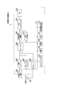
- FIG. 1 is a schematic block diagram of a signal processing device according to a first embodiment of the present invention. It is a conceptual diagram which shows an example of the positional relationship of the object pixel and comparison pixel which concern on this embodiment. It is a conceptual diagram which shows an example of the positional relationship of the object pixel and comparison pixel which concern on this embodiment. It is a conceptual diagram which shows an example of the positional relationship of the comparison pixel contained in each of the object pixel which concerns on this embodiment, and the flame
- the luminance signal Y i + 1, Y i is a conceptual diagram showing the relationship between the Y i-1 and the noise estimate. It is a table
- the luminance signal Y i + 1, Y i is a conceptual diagram showing the relationship between the luminance signal of the target pixel after the Y i-1 and the noise reduction processing. It is a flowchart which shows the signal processing which the signal processing apparatus which concerns on this embodiment performs. It is the schematic which shows the structure of the signal processing apparatus which concerns on the 2nd Embodiment of this invention. It is a flowchart which shows an example of the signal processing which the signal processing apparatus which concerns on this embodiment performs. It is a flowchart which shows the other example of the signal processing which the signal processing apparatus concerning this embodiment performs. It is the schematic which shows the structure of the video display apparatus which concerns on this embodiment.
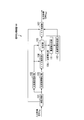
- FIG. 1 is a schematic block diagram of a signal processing apparatus 100 according to the present embodiment.
- the signal processing apparatus 100 includes a temporary storage unit 101, a target pixel reading unit 102, a comparison pixel reading unit 103, a noise estimation unit 104, a storage unit 105, a frequency calculation unit 106, and a noise reduction unit 107.
- the temporary storage unit 101 temporarily stores the input video signal SIN for M frames (M is a predetermined number of frames and is a natural number greater than 1 or 1).
- a frame is a set of signals for a plurality of pixels constituting one image.
- the input video signal SIN is, for example, a progressive display video signal for scanning pixels one by one in the main scanning direction (horizontal [horizontal] direction) for one frame of video.
- This video signal is a signal obtained by decoding a video signal extracted from, for example, an MPEG (Moving Picture Experts Group) -2TS (Transport Stream, Transport Stream) signal.
- the signal of each pixel constituting the video signal includes a luminance value, that is, a luminance signal (Y) indicating intensity, a color difference signal Cb (U) indicating a difference between the luminance value and the blue component value, and a difference between the luminance value and the red component value. It is a signal expressed in the YUV format composed of a combination of the color difference signals Cr (V) shown.
- the target pixel reading unit 102 reads a video signal of a frame (hereinafter referred to as a target frame) including a pixel to be processed (hereinafter referred to as a target pixel) from the temporary storage unit 101, and for each target pixel from the read video signal.
- the luminance signal is extracted.
- the target pixel reading unit 102 outputs the extracted luminance signal of the target pixel to the noise estimation unit 104 and stores it in the storage unit 105.
- the comparison pixel reading unit 103 reads a video signal of a frame including a pixel to be compared (hereinafter referred to as a comparison pixel) from the temporary storage unit 101, and extracts a luminance signal of the comparison pixel from the read video signal.
- the comparison pixel reading unit 103 outputs the extracted luminance signal of the comparison pixel to the noise estimation unit 104.
- the noise component superimposed on the video signal is the component superimposed on each pixel arranged in the horizontal direction in the frame (horizontal noise), and the component superimposed on each pixel arranged in the vertical direction in the frame (vertical) Noise) or a component superimposed between frames (interframe noise).
- the comparison pixel readout unit 103 for example, as the luminance signal of the comparison pixel, for example, the luminance signal Y i + 1 of the pixel i + 1 on the right side of the target pixel i and the luminance signal Y i of the pixel i-1 on the left side of the target pixel i.
- Read -1 the target pixel reading unit 102 reads the luminance signal Y i of the target pixel i.
- each of the comparison pixel i-1, the target pixel i, and the comparison pixel i + 1 is a pixel that is included in one frame and has the same vertical coordinate, and is aligned horizontally from left to right. Yes.
- the signal processing apparatus 100 reduces horizontal noise.
- the present invention is not limited to this, and the signal processing apparatus 100 may reduce vertical noise or between frames. Noise may be reduced.
- the comparison pixel reading unit 103 uses, for example, the luminance signal Y j + 1 of the pixel j + 1 below the target pixel j as the luminance signal of the comparison pixel. Then, the luminance signal Y j ⁇ 1 of the pixel j ⁇ 1 adjacent to the target pixel j is read out.
- each of the comparison pixel j-1, the target pixel j, and the comparison pixel j + 1 is a pixel that is included in one frame and has the same horizontal coordinate, and is aligned in the vertical direction from top to bottom. Yes.
- the comparison pixel reading unit 103 is included in the frame t + 1 immediately after the target frame as the luminance signal of the comparison pixel, for example, And the luminance signal Y t + 1 of the pixel t + 1 having the same horizontal and vertical coordinates, and the luminance signal of the pixel t-1 having the same horizontal and vertical coordinates as those of the target pixel. Read Y t ⁇ 1 .
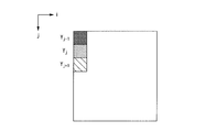
- FIG. 4 is a conceptual diagram showing an example of the positional relationship between the target pixel t included in a certain target frame and the comparison pixels t ⁇ 1 and t + 1 included in the immediately preceding and subsequent frames. In FIG.
- the horizontal axis indicates the coordinate i of the pixel in the horizontal direction
- the vertical axis indicates the coordinate j of the pixel in the vertical direction
- the axis to the lower right indicates the frame order t.
- the comparison pixel t-1, the target pixel t, and the comparison pixel t + 1 are all pixels having the same horizontal and vertical coordinates, and are arranged in chronological order for each frame.
- noise superimposed on a video signal can be reduced for a video signal for interlace display instead of a video signal for progressive display.
- Interlaced display video signals are, for example, an even field that scans every other column for even columns in the main scanning direction (horizontal [horizontal] direction), and an odd number that scans every other column for odd columns. Consists of fields.
- the signal processing apparatus 100 reduces horizontal noise in a noise reduction unit 107 described later for a video signal for interlace display.
- the comparison pixel reading unit 103 uses, as the luminance signal of the comparison pixel, for example, the luminance signal Y i + 1,2j + 1 of the pixel (i + 1, 2j + 1) to the right of the target pixel (i, 2j + 1) and the target pixel i.
- the luminance signals Y i ⁇ 1,2j + 1 of the pixel (i ⁇ 1,2j ⁇ 1) on the left side are read out.
- the target pixel reading unit 102 reads the luminance signal Y i, 2j + 1 of the target pixel (i, 2j + 1).
- the comparison pixel readout unit 103 uses, for example, the luminance signal Y i + 1,2j of the pixel (i + 1, 2j) right next to the target pixel (i, 2j) and the target pixel i as the luminance signal of the comparison pixel.
- the luminance signals Y i ⁇ 1,2j of the pixel (i ⁇ 1,2j) on the left are read.
- the target pixel reading unit 102 reads the luminance signal Y i, 2j of the target pixel (i, 2j).
- FIG. 5 is a conceptual diagram showing another example of the positional relationship between the target pixel and the comparison pixel.
- the horizontal axis indicates the coordinate i of the pixel in the horizontal direction
- the vertical axis indicates the coordinate j of the pixel in the vertical direction.
- the left column of FIG. 5 shows the entire display image.
- the comparison pixel i ⁇ 1, 2j
- the target pixel i, 2j
- the comparison pixel i + 1, 2j
- the comparison pixel i ⁇ 1, 2j + 1
- the upper right part of FIG. 5 shows an even field.
- the comparison pixel In the even field, from left to right, the comparison pixel (i ⁇ 1, 2j), the target pixel (i, 2j), and the comparison pixel (i + 1, 2j).
- the lower right part of FIG. 5 shows odd fields. In order from left to right in the odd field, there are a comparison pixel (i ⁇ 1, 2j + 1), a target pixel (i, 2j + 1), and a comparison pixel (i + 1, 2j + 1).
- the interlaced display video signal is the same as the progressive display video signal in that the pixels on both the left and right sides of the target pixel are comparison pixels.
- the comparison pixel readout unit 103 for example, as the luminance signal of the comparison pixel, for example, the luminance signal Y 2j + 3 of the pixel 2j + 3 below the target pixel 2j + 1 and the luminance signal of the pixel 2j-1 above the target pixel i Read Y 2j-1 .
- the target pixel reading unit 102 reads the luminance signal Y 2j + 1 of the target pixel 2j + 1.
- the comparison pixel readout unit 103 for example, as the luminance signal of the comparison pixel, for example, the luminance signal Y 2j + 2 of the pixel 2j + 2 below the target pixel 2j and the luminance signal of the pixel 2j-2 above the target pixel i Read Y 2j-2 .
- the target pixel reading unit 102 reads the luminance signal Y 2j of the target pixel 2j.
- FIG. 6 is a conceptual diagram showing another example of the positional relationship between the target pixel and the comparison pixel.
- the horizontal axis indicates the coordinate i of the pixel in the horizontal direction
- the vertical axis indicates the coordinate j of the pixel in the vertical direction.
- the left column in FIG. 6 shows the entire display image.
- the upper right part of FIG. 6 shows an even field.
- the comparison pixel 2j-2, the target pixel 2j, and the comparison pixel 2j + 2 are sequentially arranged from top to bottom.
- the lower right part of FIG. 6 shows an odd field. In the odd field, from the top to the bottom, the comparison pixel 2j-1, the target pixel 2j + 1, and the comparison pixel 2j + 3.
- the comparison pixel reading unit 103 includes, for example, the luminance signal of the comparison pixel in the even field, for example, in the frame t + 1 immediately after the target frame, and the pixel (2j, t + 1) having the same horizontal and vertical coordinates as the target pixel.
- the luminance signal Y 2j, t + 1 and the luminance signal Y 2j, t ⁇ 1 of the pixel (2j, t ⁇ 1) included in the frame immediately before the target frame and having the same horizontal and vertical coordinates as the target pixel are read out. .
- the comparison pixel readout unit 103 includes, as a luminance signal of the comparison pixel in the odd field, for example, a pixel (2j + 1, t + 1) that is included in the frame t + 1 immediately after the target frame and has the same horizontal and vertical coordinates as the target pixel. included in the immediately preceding frame of the luminance signal Y 2j + 1, t + 1 , and the target frame, the target pixel and horizontal and vertical coordinates reads the luminance signal Y 2j + 1, t-1 of the same pixel (2j + 1, t-1 ) .
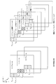
- FIG. 7 is a conceptual diagram showing another example of the positional relationship between a target pixel included in a certain target frame and comparison pixels included in the immediately preceding and subsequent frames.
- the horizontal axis indicates the coordinate i of the pixel in the horizontal direction
- the vertical axis indicates the coordinate j of the pixel in the vertical direction
- the axis to the lower right indicates the frame order t.
- the left column of FIG. 7 shows the entire display image in the immediately preceding frame t-1, the target frame t, and the immediately following frame t + 1 in order from the upper left to the lower right.
- the comparison pixels (2j, t ⁇ 1) and (2j + 1, t ⁇ 1) are sequentially arranged from top to bottom.
- the target pixels (2j, t) and (2j + 1, t) are sequentially from top to bottom.
- the comparison pixels (2j, t + 1) and (2j + 1, t + 1) are in order from top to bottom.
- the right column of FIG. 7 shows, in order from the upper left to the lower right, the even field in the previous frame t-1, the odd field in the previous frame t-1, the even field in the target frame t, the odd field in the target frame t, An even field in frame t + 1 and an odd field in immediately following frame t + 1 are shown.
- the comparison pixels (2j, t + 1) are all included in one frame and are arranged in parallel in time series.
- the signal processing apparatus 100 may reduce any combination of horizontal noise, vertical noise, and inter-frame noise.
- the signal processing apparatus 100 may reduce all three types of noise.
- the noise estimation unit 104 calculates an estimated value of noise in the target pixel based on the luminance signal of the target pixel input from the target pixel reading unit 102 and the luminance signal of the comparison pixel input from the comparison pixel reading unit 103. .
- the noise estimation unit 104 stores the absolute value of the calculated noise estimation value (hereinafter simply referred to as a noise estimation value) in the storage unit 105 in association with the luminance signal and the noise estimation value for each target pixel.
- the noise estimation unit 104 calculates an estimated value of noise using, for example, the following equation (1).
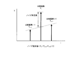
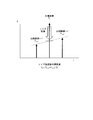
- FIG. 8 is a conceptual diagram showing the relationship between the luminance signals Y i + 1 , Y i , Y i ⁇ 1 and the noise estimation value.
- the horizontal axis indicates the coordinate i of the pixel in the horizontal direction
- the vertical axis indicates the luminance value Y in the vertical direction.
- the upward arrows in FIG. 8 indicate the luminance signals Y i + 1 , Y i, and Y i ⁇ 1 of the pixels at the coordinates i + 1, i, and i ⁇ 1 , respectively.
- the noise estimate value N i is the absolute value of the luminance signal Y i, compare the pixel i-1, i + 1 of the luminance signal Y i-1, a value obtained by subtracting the Y i + 1 of the average value of the target pixel i Show.
- the frequency calculation unit 106 includes a mode value determination unit 111 and a reduction range determination unit 112.
- the mode value determining unit 111 reads the estimated noise value for each frame including the target pixel to be processed from the storage unit 105.
- the mode value determination unit 111 counts the number of pixels (appearance frequency) in the section to which the estimated value belongs for each estimated noise value read in the frame.
- An example of the appearance frequency for each section of the noise estimation value is shown in FIG.
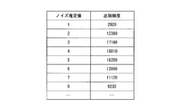
- FIG. 9 is a table showing an example of the representative value and the appearance frequency for each section of the noise estimation value according to the present embodiment.
- the estimated noise values shown in FIG. 9 are representative values, and sections are set so as to be rounded to integer values (that is, the section width is 1). In FIG.
- the appearance frequencies for the noise estimates 1, 2, 3, 4, 5, 6, 7, and 8 are 2920, 12380, 17160, 18010, 16350, 13990, 11120, and 9230, respectively.
- the section width for counting the appearance frequency is not limited to 1, and any real number can be set as the section width as long as the distribution of the appearance frequency can be expressed.
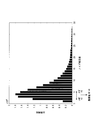
- FIG. 10 is a diagram illustrating an example of the filing frequency for each estimated noise value (representative value) according to the present embodiment.
- the horizontal axis indicates the noise estimation value
- the vertical axis indicates the appearance frequency.
- FIG. 10 illustrates the appearance frequency for each estimated noise value illustrated in FIG. 9.
- the mode value determination unit 111 determines the representative value of the section of the estimated noise estimation value having the highest application frequency as the mode value, and outputs the determined mode value to the reduction range determination unit 112. In the example shown in FIG. 10, the mode value is 4.
- the reduction range determination unit 112 determines the reduction range based on the mode value input from the mode value determination unit 111.
- the reduction range is a range of a noise estimation value of a target pixel on which noise reduction processing is performed in the noise reduction unit 107. That is, noise reduction processing is not performed for pixels that are target pixels whose estimated noise values are outside the reduction range.
- the reduction range determination unit 112 determines the reduction range so that the minimum value of the noise estimation value is ⁇ N ′ and the maximum value is ⁇ N ′, for example.
- N ′ is the mode value.
- ⁇ is a preset real value larger than zero and smaller than 1, for example, 0.5 or more and 0.75 or less.
- ⁇ is a preset real value of 1 or more, for example, 1 or more and 1.25 or less.
- the minimum value and the maximum value are determined to be 2 and 5, respectively.
- the reduction range determination unit 112 outputs the minimum value and the maximum value of the noise estimation value indicating the determined reduction range to the noise reduction unit 107.
- the noise reduction unit 107 reads the luminance signal of the target pixel and the corresponding noise estimation value for each frame from the storage unit 105.
- the noise reduction unit 107 determines whether the estimated noise value corresponding to each target pixel is within the reduction range input from the reduction range determination unit 112. When the estimated noise value is within the reduction range, noise reduction processing is performed for the corresponding target pixel. For example, the noise reduction unit 107 sets the luminance signal Y i of the target pixel to the average value (Y i ⁇ 1 + Y i + 1 ) / 2 of the luminance signal of the comparison pixel.
- FIG. 11 is a conceptual diagram showing the relationship between the luminance signals Y i + 1 , Y i , Y i ⁇ 1 and the luminance signal of the target pixel after noise reduction processing according to the present embodiment.
- the horizontal axis represents the pixel coordinate i in the horizontal direction
- the vertical axis represents the luminance value Y.
- the upward arrows in FIG. 11 indicate the luminance signals Y i + 1 , Y i, and Y i ⁇ 1 of the pixels at the coordinates i + 1, i, and i ⁇ 1 , respectively.
- FIG. 11 is a conceptual diagram showing the relationship between the luminance signals Y i + 1 , Y i , Y i ⁇ 1 and the luminance signal of the target pixel after noise reduction processing according to the present embodiment.
- the horizontal axis represents the pixel coordinate i in the horizontal direction
- the vertical axis represents the luminance value Y.
- the upward arrows in FIG. 11 indicate the luminance
- noise reduction processing is performed by setting the luminance signal Y i of the target pixel i to the average value of the luminance signals Y i ⁇ 1 and Y i + 1 of the comparison pixels i ⁇ 1 and i + 1. Note that the noise reduction unit 107 does not perform noise reduction processing on the target pixel when the estimated noise value of the target pixel is outside the reduction range.
- the noise reduction unit 107 reads the corresponding color difference signals C b and C r from the temporary storage unit 101 after the above determination and the noise reduction processing for the luminance signal Y are completed for all target pixels in the frame.
- the noise reduction unit 107 integrates the luminance signal in the frame and the read color difference signal for each pixel to reconstruct a YUV format video signal, and outputs the reconstructed video signal as an output video signal SOUT .
- the noise reduction unit 107 performs the noise reduction process on the luminance signal Y that is a part of the YUV video signal, thereby avoiding a change in color due to the process and changing only the shading.
- the change of the color by a process is accept
- the luminance signal indicating each of red, green, and blue constituting the RGB (Red Green Blue) format video signal may be processed.
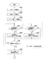
- FIG. 12 is a flowchart showing signal processing performed by the signal processing apparatus 100 according to the present embodiment.
- the target pixel reading unit 102 reads a video signal of a frame including the target pixel from the temporary storage unit 101, and extracts a luminance signal for each target pixel from the read video signal.
- the target pixel reading unit 102 outputs the extracted luminance signal of the target pixel to the noise estimation unit 104 and stores it in the storage unit 105. Thereafter, the process proceeds to step S102.
- Step S102 The comparison pixel reading unit 103 reads the video signal of the frame including the comparison pixel from the temporary storage unit 101, and extracts the luminance signal of the comparison pixel from the read video signal.
- the comparison pixel reading unit 103 outputs the extracted luminance signal of the comparison pixel to the noise estimation unit 104. Thereafter, the process proceeds to step S103.
- Step S103 The noise estimation unit 104 estimates noise in the target pixel based on the luminance signal of the target pixel input from the target pixel reading unit 102 and the luminance signal of the comparison pixel input from the comparison pixel reading unit 103. The value is calculated using, for example, formula (1).
- the noise estimation unit 104 stores the calculated noise estimation value in the storage unit 105 in association with the luminance value and the noise estimation value for each target pixel. Thereafter, the process proceeds to step S104.
- Step S104 The signal processing apparatus 100 determines whether or not the processing of steps S101 to S103 has been executed for all the pixels in the frame.
- step S104 determines that the process has been performed for all the pixels in the frame (step S104: Yes).
- step S104: No the target pixel to be processed in the frame is changed, and the process proceeds to step S101.
- pixels in the peripheral part of the frame for example, pixels located in the uppermost column, the lowermost column, the leftmost column, and the rightmost column are not processed. In the signal processing apparatus according to the present embodiment, such a pixel may be determined to have been executed regardless of whether or not an actual process is executed.
- the luminance values of the comparison pixels for each target pixel are set to be equal to each other, and the noise estimation value is set to zero (formula ( 1), and may be substantially excluded from the processing target.
- Step S105 The mode value determination unit 111 reads the estimated noise value for each frame including the target pixel from the storage unit 105, and counts the appearance frequency of the section to which the read estimated noise value belongs. Thereafter, the process proceeds to step S106.
- Step S106 The mode determining unit 111 determines the representative value of the section of the noise estimation value having the highest counted application frequency as the mode value, and outputs the determined mode value to the reduction range determining unit 112. . Thereafter, the process proceeds to step S107.
- Step S ⁇ b> 107 The reduction range determination unit 112 determines a reduction range based on the mode value input from the mode value determination unit 111. The reduction range determination unit 112 outputs the determined minimum value and maximum value of the reduction range to the noise reduction unit 107. Thereafter, the process proceeds to step S108.
- Step S ⁇ b> 108 The noise reduction unit 107 reads the luminance value of the target pixel and the corresponding noise estimation value from the storage unit 105. The noise reduction unit 107 determines whether the estimated noise value corresponding to each target pixel is within the reduction range input from the reduction range determination unit 112. When the estimated noise value is within the reduction range (step S108: Yes), the process proceeds to step S109. When the noise estimation value is outside the reduction range (step S108: No), the noise reduction unit 107 proceeds to step S110. (Step S109) The noise reduction unit 107 performs noise reduction processing on the target pixel corresponding to the noise estimation value that is the determination target. Then, it progresses to step S110.
- Step S110 The signal processing apparatus 100 determines whether or not the processing of steps S108 to S109 has been performed for all the pixels in the frame.
- the noise reduction unit 107 reads the corresponding color difference signal from the temporary storage unit 101, and the luminance signal corresponding to each pixel.
- the YUV video signal is reconstructed by integration.
- the noise reduction unit 107 outputs the reconstructed video signal as the output video signal S OUT and ends the processing.
- the signal processing apparatus 100 determines that the processing in steps S108 to S109 has not been executed for all pixels in the frame (step S110: No)
- the target pixel to be processed in the frame is changed, and step S108 is performed. Proceed to
- the comparison pixel is each pixel adjacent to the left and right of the target pixel, each pixel adjacent to the top and bottom of the target pixel, or each pixel (two) of the frame immediately before or after the target pixel.
- the comparison pixel may be a pixel that is one pixel or more away from the target pixel by a predetermined (first) interval (for example, two pixels or three pixels).
- the signal processing apparatus 100 may use two or more predetermined numbers (for example, three or four) of comparison pixels for each target pixel.
- the reduction range in which the noise reduction process is performed is determined such that the minimum value of the noise estimation value is ⁇ N ′ and the maximum value is ⁇ N ′, but the present invention is not limited to this.
- the reduction range determination unit 112 may determine, as the reduction range, a noise estimation value whose appearance frequency is equal to or higher than the threshold T th .
- This threshold value T th may be a preset fixed value smaller than the maximum value of the appearance frequency, or a value determined based on the maximum value of the appearance frequency, for example, a multiple of the maximum value greater than zero and smaller than 1. May be. If the reduction range is determined in this way, the reduction range can be uniquely determined even when the appearance frequency has a plurality of maximum values.
- the noise of the target signal is reduced for each target pixel based on the frequency distribution of the noise estimation value based on the difference between the target signal and the intensity of the comparison signal. Based on the determination, a target signal for reducing noise is selected, and deterioration in image quality can be prevented.
- the noise of the target signal when the estimated value of the target signal is included in the range of the predetermined estimated value including the estimated value having the maximum frequency, the noise of the target signal is reduced. Noise components that affect image quality are reduced.
- the frequency distribution of the noise estimated value is calculated for each frame, and the minimum value of the estimated value range for reducing noise is ⁇ times the estimated value at the maximum frequency value ( ⁇ is 1).
- the maximum value of the range of the noise estimated value for reducing noise is ⁇ times the estimated value at the maximum value of the frequency ( ⁇ is a real number larger than 1), and ⁇ is 0.5 or more and 0.75. In the following, ⁇ is 1 or more and 1.25 or less. Therefore, the minute component of the video represented by the estimated value of the noise component that is less than the minimum value, and the rapidly changing component of the video represented by the estimated value of the noise component that exceeds the maximum value remain. Reproducible images.
- the intensity of the target signal is calculated based on the intensity of the comparison signal that is separated from the target pixel by a predetermined interval, a component whose luminance value fluctuates with a space width equal to or less than the interval is mainly used. The noise which becomes can be reduced.
- the average value of the comparison signals arranged on both sides of the target signal is calculated as the intensity of the target signal, a component whose luminance value fluctuates with a space width equal to or less than the pixel interval is mainly used. Can be reduced.
- FIG. 13 is a schematic diagram illustrating the configuration of the signal processing device 200 according to the present embodiment.
- the signal processing apparatus 200 includes a temporary storage unit 201, a noise amount calculation unit 202, a noise reduction unit 203, a comparison pixel extraction unit 204, and a signal processing unit 250.
- the configuration of the signal processing unit 250 is the same as that of the signal processing device 100 shown in FIG. That is, the signal processing device 200 is configured to include a temporary storage unit 201, a noise amount calculation unit 202, a noise reduction unit 203, and a comparison pixel reading unit 204 in front of the signal processing unit 250.
- the output video signal X OUT from the noise reduction unit 203 for the input video signal X IN to the signal processing device 200 becomes the input video signal S IN to the signal processing unit 250.
- the temporary storage unit 201 temporarily stores the input video signal XIN for a predetermined number of frames.
- the noise amount calculation unit 202 includes a horizontal noise amount calculation unit 221, a vertical noise amount calculation unit 222, and an inter-frame noise amount calculation unit 223.
- the noise reduction unit 203 includes an inter-frame noise reduction unit 231, a horizontal noise reduction unit 232, and a vertical noise reduction unit 233.
- the horizontal noise amount calculation unit 221 reads out the video signal of the frame including the target pixel to be processed from the temporary storage unit 201.
- the horizontal noise amount calculation unit 221 estimates a horizontal noise amount corresponding to a noise component superimposed on video signals of pixels arranged in the horizontal direction in the same frame. In order for the horizontal noise amount calculation unit 221 to estimate the horizontal noise amount, for example, a method in which the noise estimation unit 104 estimates noise may be used.
- the horizontal noise amount calculation unit 221 outputs the estimated horizontal noise amount to the inter-frame noise amount calculation unit 223 and the horizontal noise reduction unit 232.
- the vertical noise amount calculation unit 222 reads out the video signal of the frame including the target pixel to be processed from the temporary storage unit 201.
- the vertical noise amount calculation unit 222 estimates the vertical noise amount corresponding to the noise component superimposed on the video signals of pixels arranged in the vertical direction in the same frame. In order for the vertical noise amount calculation unit to estimate the vertical noise amount, for example, a method in which the noise estimation unit 104 estimates noise may be used.
- the vertical noise amount calculation unit 222 outputs the estimated vertical noise amount to the inter-frame noise amount calculation unit 223 and the vertical noise reduction unit 233.
- the inter-frame noise amount calculation unit 223 superimposes the average value of the horizontal noise amount input from the horizontal noise amount calculation unit 221 and the vertical noise amount input from the vertical noise amount calculation unit 222 on the inter-frame pixel signal. This is calculated as an inter-frame noise amount representing the amount of the noise component being processed.
- the inter-frame noise amount calculation unit 223 outputs the calculated inter-frame noise amount to the inter-frame noise reduction unit 231 provided in the noise reduction unit 203.
- the comparison pixel reading unit 204 includes an inter-frame comparison pixel reading unit 241, a horizontal direction comparison pixel reading unit 242, and a vertical direction comparison pixel reading unit 243.
- the inter-frame comparison pixel reading unit 241 reads out the video signal of the frame one frame before the frame including the target pixel to be processed from the temporary storage unit 201.
- the inter-frame comparison pixel reading unit 241 reads the luminance signal of the pixel existing at the same position as the target pixel from the read video signal as the luminance signal Y t-1 one frame before, and reads the read luminance signal Y t- 1 is output to the inter-frame noise reduction unit 231.
- the inter-frame comparison pixel reading unit 241 reads the video signal of the frame one frame after the frame including the target pixel to be processed from the temporary storage unit 201.
- the inter-frame comparison pixel reading unit 241 reads the luminance signal of the pixel existing at the same position as the target pixel from the read video signal as the luminance signal Y t + 1 after one frame, and reads the read luminance signal Y t + 1 between the frames. Output to the noise reduction unit 231.
- the horizontal comparison pixel reading unit 242 reads out the video signal of the frame including the target pixel to be processed from the temporary storage unit 201.
- the horizontal direction comparison pixel reading unit 242 reads out the luminance signal of the pixel existing on the right side of the target pixel as the luminance signal Y i + 1 on the right side from the read video signal, and reads the read luminance signal Y i + 1 on the horizontal noise reduction unit 232. Output to.
- the horizontal direction comparison pixel reading unit 242 reads out the luminance signal of the pixel existing on the left side of the target pixel from the video signal of the frame read out from the temporary storage unit 201 as the luminance signal Y i-1 on the left side, and reads the read luminance
- the signal Y i ⁇ 1 is output to the horizontal noise reduction unit 232.
- the vertical direction comparison pixel reading unit 243 reads the video signal of the frame including the target pixel to be processed from the temporary storage unit 201.
- the vertical direction comparison pixel reading unit 243 reads the luminance signal of the pixel existing above the target pixel as the upper adjacent luminance signal Y j ⁇ 1 from the read video signal, and vertically reads the read luminance signal Y j ⁇ 1 . Output to the noise reduction unit 233.
- the vertical direction comparison pixel reading unit 243 reads out the luminance signal of the pixel existing below the target pixel from the video signal of the frame read out from the temporary storage unit 201 as the luminance signal Y j + 1 on the left side, and reads out the read luminance signal Y j + 1 is output to the vertical noise reduction unit 233.
- the noise reduction unit 203 includes an inter-frame noise reduction unit 231, a horizontal noise reduction unit 232, and a vertical noise reduction unit 233.
- the inter-frame noise reduction unit 231 reads out the video signal of the frame including the target pixel to be processed from the temporary storage unit 201.
- the inter-frame noise reduction unit 231 includes, for all pixels constituting the video signal of the read frame, the luminance signal Y t of each pixel, the luminance signal Y t-1 one frame before the pixel, and one frame of the pixel Based on the later luminance signal Y t + 1 , processing for reducing the inter-frame noise is performed.
- the inter-frame noise reduction unit 231 determines the luminance signal Y t as the average value of the luminance signal Y t ⁇ 1 and the luminance signal Y t + 1 in the same manner as the noise estimation unit 104.
- the inter-frame noise reduction unit 231 outputs the luminance signal subjected to the processing for reducing the inter-frame noise to the horizontal noise reduction unit 232.
- the horizontal noise reduction unit 232 for all pixels constituting the luminance signal input from the inter-frame noise reduction unit 231, the luminance signal Y i of each pixel, the luminance signal Y i-1 adjacent to the left of the pixel, and its A process for reducing horizontal noise is performed based on the luminance signal Y i + 1 on the right side of the pixel. For example, similarly to the noise estimation unit 104, the horizontal noise reduction unit 232 determines the luminance signal Y i as the average value of the luminance signal Y i ⁇ 1 and the luminance signal Y i + 1 . The horizontal noise reduction unit 232 outputs the luminance signal subjected to the process of reducing the horizontal noise to the vertical noise reduction unit 233.
- the vertical noise reduction unit 233 for all the pixels constituting the luminance signal input from the horizontal noise reduction unit 232, the luminance signal Y j of each pixel, the luminance signal Y j ⁇ 1 adjacent to the pixel, and the pixel A process of reducing vertical noise is performed on the basis of the luminance signal Y j + 1 next to. For example, similar to the noise estimation unit 104, the vertical noise reduction unit 232 determines the luminance signal Y i as the average value of the luminance signal Y j ⁇ 1 and the luminance signal Y j + 1 . The vertical noise reduction unit 233 outputs a luminance signal that has been subjected to processing for reducing vertical noise.
- Noise reduction unit 203 reads from the color difference signals Cb, and Cr temporary storage unit 201 of the pixel, the corresponding luminance signal Y and integrated for each pixel, the signal processing unit 250 as a video signal X OUT as represented in the YUV format Output.
- the target pixel reading unit 102 included in the signal processing unit 250 may read the target pixel from the temporary storage unit 201 and extract a luminance signal from the read target pixel.
- the comparison pixel reading unit 103 may read the comparison pixel from the temporary storage unit 201 and extract a luminance signal from the read comparison pixel.
- the signal processing unit 250 may omit the temporary storage unit 101. Further, by omitting the temporary storage unit 101, it is possible to avoid a delay caused by temporarily storing the video signal.
- the comparison pixel reading unit 204 may output the extracted luminance signal of the comparison pixel to the noise estimation unit 104. In that case, the comparison pixel reading unit 103 can be omitted.
- Step S ⁇ b> 201 The horizontal noise amount calculation unit 221 reads out a video signal of a frame including the target pixel to be processed from the temporary storage unit 201.
- the horizontal noise amount calculation unit 221 calculates a horizontal noise amount corresponding to a noise component superimposed on video signals of pixels arranged in the horizontal direction in the same frame.
- Horizontal noise amount calculation section 221 for example, the comparison between the luminance signal Y i of the target pixel i the pixel i-1, i + 1 the luminance signal Y i-1, Y i + 1 to the basis (1) horizontal noise amount using the N i Is calculated.
- the horizontal noise amount calculation unit 221 outputs the estimated horizontal noise amount to the average noise amount calculation unit 223 and the horizontal noise reduction unit 232. Thereafter, the process proceeds to step S202.
- Step S202 The vertical noise amount calculation unit 222 reads the video signal of the frame including the target pixel to be processed from the temporary storage unit 201.
- the vertical noise amount calculation unit 222 estimates the vertical noise amount corresponding to the noise component superimposed on the video signals of pixels arranged in the vertical direction in the same frame.
- Vertical noise amount calculation section 221 for example, the comparison between the luminance signal Y j of the target pixel j pixel j-1, j + 1 the luminance signal Y j-1, Y j + vertical noise amount using 1 based equation (1) N j Is calculated.
- the vertical noise amount calculation unit 221 outputs the calculated vertical noise amount to the average noise amount calculation unit 223 and the vertical noise reduction unit 233. Thereafter, the process proceeds to step S203.
- the inter-frame noise amount calculation unit 223 calculates, for example, an average value of the horizontal noise amount input from the horizontal noise amount calculation unit 221 and the vertical noise amount input from the vertical noise amount calculation unit 222 as a frame. It is calculated as an inter-frame noise amount that represents the amount of the noise component superimposed on the inter-pixel signal.
- the inter-frame noise amount calculation unit 223 outputs the calculated inter-frame noise amount to the inter-frame noise reduction unit 231 provided in the noise reduction unit 203.
- the inter-frame comparison pixel reading unit 241 reads the video signal of the frame one frame before and the video signal of one frame after the frame including the target pixel to be processed from the temporary storage unit 201.
- the inter-frame comparison pixel reading unit 241 converts the luminance signal of the pixel existing at the same position as the target pixel from the read video signal as the luminance signal Y t ⁇ 1 one frame before and the luminance signal Y t + 1 one frame before.
- the read luminance signals Y t ⁇ 1 and Y t + 1 are output to the interframe noise reduction unit 231 as comparison signals.
- the inter-frame noise reduction unit 231 reads the luminance signal Y t of the target pixel from the temporary storage unit 201 and compares it with the luminance signals Y t ⁇ 1 and Y t + 1 of the comparison pixel input from the inter-frame comparison pixel reading unit 241. , the luminance signal Y t of the target pixel is determined whether the minimum. If the luminance signal Y t of the target pixel is minimum, the process proceeds to step S205. (Step S204: Yes) when the luminance signal Y t of the target pixel is not a minimum, the process proceeds to step S206.
- Step S204 No
- Step S205 The inter-frame noise reduction unit 231 adds the inter-frame noise amount input from the inter-frame noise amount calculation unit 223 to the luminance signal Y t of the target pixel. Thereafter, the process proceeds to step S208.
- Step S206 The inter-frame noise reduction unit 231 compares the luminance signal Y t of the target pixel with the luminance signals Y t ⁇ 1 and Y t + 1 of the comparison pixels input from the inter-frame comparison pixel reading unit 241. luminance signal Y t of the target pixel is determined whether the maximum. When the luminance signal Y t of the target pixel is maximum, the process proceeds to step S207 (step S206: Yes). When the luminance signal Y t of the target pixel is not maximized, the process proceeds to step S208 (No in step S206).
- Step S207 The inter-frame noise reduction unit 231 subtracts the inter-frame noise amount input from the inter-frame noise amount calculation unit 223 from the luminance signal Y t of the target pixel. Thereafter, the process proceeds to step S208.
- Step S208 The inter-frame noise reduction unit 231 determines whether or not the luminance signal of the target pixel and the luminance signal of the comparison pixel have been compared for all the pixels in the frame. If the determination has not been completed for all the pixels, the target pixel is changed to one of the undetermined pixels (step S208: No). Thereafter, the process proceeds to step S204. If the determination is completed for all pixels, the process proceeds to step S209 (step S208: Yes).
- Step S ⁇ b> 209 The interframe noise reduction unit 231 outputs the video signal of the frame subjected to the interframe noise reduction processing to the horizontal noise reduction unit 232.
- Step S ⁇ b> 210) The horizontal direction comparison pixel reading unit 242 reads out the video signal of the frame including the target pixel to be processed from the temporary storage unit 201.
- Horizontal comparison image pixel read unit 242, the read video signal reads the luminance signal Y i + 1 of the luminance signal Y i-1 and the right pixel to the left of the pixel of the target pixel, the read luminance signal Y i-1 , Y i + 1 are output as comparison signals to the horizontal noise reduction unit 232.
- the horizontal noise reduction unit 232 receives the luminance signal Y i of the target pixel from the video signal input from the inter-frame noise reduction unit 231 and the luminance signal Y i ⁇ 1 of the comparison pixel input from the horizontal direction comparison pixel reading unit 242. Compared with Y i + 1, it is determined whether or not the luminance signal Y i of the target pixel is minimized. If the luminance signal Y i of the target pixel is minimum, the process proceeds to step S211. (Step S210: Yes) When the luminance signal Y i of the target pixel is not minimized, the process proceeds to Step S212 (No in Step S210). (Step S211) The horizontal noise reduction unit 232 adds the horizontal noise amount input from the horizontal noise amount calculation unit 221 to the luminance signal Y t of the target pixel. Thereafter, the process proceeds to step S214.
- Step S212 The horizontal noise reduction unit 232 compares the luminance signal Y i of the target pixel with the luminance signals Y i ⁇ 1 and Y i + 1 of the comparison pixels input from the horizontal direction comparison pixel reading unit 242 to determine the target It is determined whether or not the pixel luminance signal Y i is maximized.
- the process proceeds to step S213 (step S212: Yes).
- the process proceeds to step S214 (No in step S212).
- Step S213 The horizontal noise reduction unit 232 subtracts the horizontal noise amount input from the horizontal noise amount calculation unit 221 from the luminance signal Y i of the target pixel. Thereafter, the process proceeds to step S214.
- Step S214 The horizontal noise reduction unit 232 determines whether the luminance signal of the target pixel and the luminance signal of the comparison pixel have been compared for all the pixels in the frame. If the determination is not completed for all the pixels, the target pixel is changed to one of the undetermined pixels (step S214: No). Thereafter, the process proceeds to step S210. If the determination is completed for all the pixels, the process proceeds to step S215 (step S214: Yes).
- Step S215 The horizontal noise reduction unit 232 outputs the video signal of the frame subjected to the horizontal noise reduction process to the vertical noise reduction unit 233.
- the vertical direction comparison pixel reading unit 243 reads out the video signal of the frame including the target pixel to be processed from the temporary storage unit 201.
- the vertical direction comparison pixel reading unit 243 reads the luminance signal Y j ⁇ 1 of the lower adjacent pixel and the luminance signal Y j + 1 of the upper adjacent pixel from the read video signal, and reads the read luminance signal Y j ⁇ 1.
- Y j + 1 are output as comparison signals to the vertical noise reduction unit 233.
- the vertical noise reduction unit 233 receives the luminance signal Y j of the target pixel from the video signal input from the horizontal noise reduction unit 232 and the luminance signal Y j ⁇ 1 , Y of the comparison pixel input from the vertical comparison pixel reading unit 243. Compared with j + 1 , it is determined whether or not the luminance signal Y j of the target pixel is minimized. If the luminance signal Yj of the target pixel is minimum, the process proceeds to step S217. (Step S216: Yes) When the luminance signal Yj of the target pixel is not minimized, the process proceeds to Step S218 (No in Step S216). (Step S217) The vertical noise reduction unit 233 adds the vertical noise amount input from the vertical noise amount calculation unit 222 to the luminance signal Yj of the target pixel. Thereafter, the process proceeds to step S220.
- Step S228 The vertical noise reduction unit 233 compares the luminance signal Y j of the target pixel with the luminance signals Y j ⁇ 1 and Y j + 1 of the comparison pixel input from the vertical comparison pixel reading unit 243, and It is determined whether or not the luminance signal Y j is maximized.
- the process proceeds to step S219 (step S218: Yes).
- the process proceeds to step S220 (step S218: No).
- Step S219) The vertical noise reduction unit 233 subtracts the vertical noise amount input from the vertical noise amount calculation unit 222 from the luminance signal Y j of the target pixel. Thereafter, the process proceeds to step S220.
- Step S220 The vertical noise reduction unit 233 determines whether or not the luminance signal of the target pixel and the luminance signal of the comparison pixel have been compared for all the pixels in the frame. If the determination has not been completed for all the pixels, the target pixel is changed to one of the undetermined pixels (step S220: No). Thereafter, the process proceeds to step S216. If the determination is completed for all the pixels, the process proceeds to step S221 (step S220: Yes).
- Step S221 The vertical noise reduction unit 233 outputs the video signal of the frame subjected to the vertical noise reduction process to the signal processing unit 250 as the output video signal XOUT .
- Step S222 the signal processing unit 250, a video signal X OUT from the vertical noise reduction unit 233 is input as the input video signal S IN, executes the processing shown in FIG. 12. Thereafter, the process ends.
- FIG. 16 is a schematic diagram illustrating a configuration of the video display apparatus 300 according to the present embodiment.
- the video display apparatus 300 includes a receiving antenna 301, an external input terminal 302, an HDMI (High-Definition Multimedia Interface) receiver 303, a disk drive 304, a tuner 305, a selector 306, and a network IF (Interface) 307.
- HDMI High-Definition Multimedia Interface
- ROM Read-Only Memory
- RAM Random Access Memory
- CPU Central Processing Unit
- Infrared light receiver 311, OSD (On-Screen Display); On-screen display) generation unit
- LCD Liquid Cry
- LCD Liquid Cry
- the reception antenna 301 outputs a reception signal based on the received broadcast radio wave to the tuner 305.
- the external input terminal 302 outputs a signal input from the outside of the video display device 300 to the HDMI receiver 303, the disk drive 304, and the tuner 305.
- the HDMI receiver 303 converts the HDMI format signal input from the external input terminal 302 into a video signal, and outputs the converted video signal to the selector 306.
- the disk drive 304 stores the video signal input from the external input terminal 302 in a storage medium (for example, a Blu-ray disk) that stores the video signal.
- the disk drive 304 reads a video signal stored from a storage medium and outputs the read video signal to the selector 306.
- the tuner 305 demodulates the reception signal input from the reception antenna 302 or the reception signal input from the external input terminal 302 with a carrier frequency based on the operation input signal, for example, to generate a video signal, and the generated video signal is selected by the selector.
- the selector 306 selects a video signal input from any one of the HDMI receiver 303, the disk drive 304, and the tuner 305 based on, for example, an operation input signal, and outputs the selected video signal to the signal processing device 200.
- the network IF 307 is connected to a communication line (for example, a local communication line, the Internet), and a program (for example, a version upgrade program) for operating the video display device 300 is input from the communication line and stored in the ROM 308.
- the CPU 310 reads the program stored from the ROM 308, and operates each unit constituting the video display device 300 by executing the read program.
- the RAM 309 temporarily stores data generated by operating the program.
- the infrared light receiving unit 311 converts an operation input signal input by infrared rays into an operation input signal using an electrical signal, and outputs the operation input signal to the tuner 305, the selector 306, or the OSD generation unit 312.
- the OSD generation unit 312 generates an OSD signal indicating setting information based on the operation input signal input from the infrared light receiving unit 311, and outputs the generated OSD signal to the LCD controller 313.
- the signal processing apparatus 200 performs the processing shown in Figure 14-15 a video signal inputted from the selector 306 as an input video signal X IN, produces an output video signal S OUT.
- the signal processing device 200 outputs the generated output video signal S OUT to the LCD controller 313.
- the LCD controller 313 generates a display video signal by superimposing the output video signal S OUT input from the signal processing device 200 and the OSD signal input from the OSD generation unit 312.
- the LCD controller 313 outputs the generated display video signal to the LCD 314. If no OSD signal is input, the LCD controller 313 outputs the output video signal S OUT input from the signal processing device 200 to the LCD 314 as a display video signal.
- the LCD 314 displays a video based on the display video signal input from the LCD controller 313.
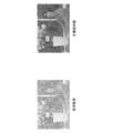
- FIG. 17 shows an example of video based on video signals before and after processing by the signal processing device.
- the upper part of FIG. 17 shows an example of video based on the video signal before processing. This image shows that noise having a spatial wavelength within several pixels is superimposed.
- the lower left part of FIG. 17 shows an example of an image based on the video signal obtained by processing the video signal shown in the upper part using a conventional signal processing device.
- This conventional signal processing apparatus corresponds to the signal processing apparatus 200 in which the signal processing unit 250 is omitted, and performs processing for reducing interframe noise, horizontal noise, and vertical noise. In this image, noise is reduced, but the outline and fine portions of the image are unclear.
- FIG. 17 shows an example of a video based on a video signal obtained by processing the video signal shown in the upper part using the signal processing apparatus 200 according to the present embodiment.
- noise is reduced as in the image on the lower left, and the contour and fine portions of the image are clear.
- FIG. 18 shows an example of an image showing a processing target pixel.
- the left side of FIG. 18 shows an image in which a white point indicating a pixel to be processed in the above-described conventional signal processing device is superimposed on an image before processing. This image shows that, in comparison with the images in the upper part of FIG. 17 and the lower left part of FIG. 17, the contour part and the fine part are the processing target in addition to the part with significant noise.
- the right side of FIG. 18 shows an image in which a white point indicating a pixel to be processed in the signal processing device 200 according to the present embodiment is superimposed on the image before processing. Compared with the images in the upper part of FIG. 17 and the lower right part of FIG. 17, this image shows that a contoured part or a fine part of the image is excluded from the processing target while a part where noise is significant is set as a processing target.
- FIG. 19 shows another example of a video showing a processing target pixel.
- all show images obtained by superimposing a white point indicating a pixel to be processed in the signal processing device 200 according to the present embodiment on an image before processing.
- the minimum value ⁇ of the range of the estimated noise value is 0.25
- ⁇ is 0.5 in the upper right part
- ⁇ is 0.75 in the lower left part
- ⁇ is 1.0 in the lower right part.
- the maximum value ⁇ in the range of the noise estimation value is 1.25.
- this example shows that when ⁇ is 0.25, many of the fine parts of the video are to be processed.
- ⁇ when ⁇ is 1, it indicates that there are too few processing points and noise cannot be reduced. Therefore, this example shows that the case where ⁇ is 0.5 or more and 0.75 or less is optimal.
- FIG. 20 shows another example of an image showing a processing target pixel.
- all show images obtained by superimposing a white point indicating a pixel to be processed in the signal processing device 200 according to the present embodiment on an image before processing.
- the maximum value ⁇ of the noise estimation value range is 1, the upper right part is ⁇ of 1.25, the lower left part is ⁇ , and the lower right part is ⁇ . Indicates.
- the minimum value ⁇ in the range of the noise estimation value is 0.5.
- this example shows that when ⁇ is 1.5 or more, most of the contour portions of the image are to be processed. Therefore, this example shows that the case where ⁇ is 1 or more and 1.25 or less is optimal.
- a video signal in which interframe noise, horizontal noise, and vertical noise are reduced from the input video signal is input to the signal processing unit 250.
- the signal processing unit 250 it is possible to exclude a part where the luminance value fluctuates rapidly and a minute component of the image from the processing target, and effectively remove a main component of noise that cannot be reduced by the signal processing unit 250 alone. it can.
- the input video signals S IN and X IN may be video signals expressed in RGB format, for example.
- the RGB format is a video signal including a luminance value of a red component (R), a luminance value of a green component (G), and a luminance value of a blue component (B) for each pixel.
- the noise estimation unit 104 the noise reduction unit 107, the noise amount calculation unit 202, and the noise reduction unit 203, the input video signals S IN and X IN in the RGB format are converted into the YUV format.
- an output signal in YUV format may be output after converting S OUT and X OUT into RGB format.
- each color component is processed in the noise estimation unit 104, noise reduction unit 107, noise amount calculation unit 202, and noise reduction unit 203. For all or some of the luminance values, the same processing as the luminance signal Y i , etc. may be performed.
- a part of the signal processing device 100 or the signal processing unit 250 in the above-described embodiment for example, the target pixel reading unit 102, the comparison pixel reading unit 103, the noise estimation unit 104, the frequency calculation unit 106, and the noise reduction unit 107,
- a part of the signal processing apparatus 200 for example, the noise amount calculation unit 202, the comparison pixel extraction unit 204, and the noise reduction unit 203 may be realized by a computer.
- the program for realizing the control function may be recorded on a computer-readable recording medium, and the program recorded on the recording medium may be read by a computer system and executed.
- the “computer system” is a computer system built in the signal processing apparatuses 100 and 200 and includes hardware such as an OS and peripheral devices.
- the “computer-readable recording medium” refers to a storage device such as a flexible medium, a magneto-optical disk, a portable medium such as a ROM or a CD-ROM, and a hard disk incorporated in a computer system. Furthermore, the “computer-readable recording medium” is a medium that dynamically holds a program for a short time, such as a communication line when transmitting a program via a network such as the Internet or a communication line such as a telephone line, In such a case, a volatile memory inside a computer system serving as a server or a client may be included and a program that holds a program for a certain period of time.
- the program may be a program for realizing a part of the functions described above, and may be a program capable of realizing the functions described above in combination with a program already recorded in a computer system.
- part or all of the signal processing devices 100 and 200 in the above-described embodiments may be realized as an integrated circuit such as an LSI (Large Scale Integration).
- LSI Large Scale Integration
- Each functional block of the signal processing devices 100 and 200 may be individually made into a processor, or a part or all of them may be integrated into a processor.
- the method of circuit integration is not limited to LSI, and may be realized by a dedicated circuit or a general-purpose processor. Further, in the case where an integrated circuit technology that replaces LSI appears due to progress in semiconductor technology, an integrated circuit based on the technology may be used.
- the present invention can be applied to a noise reduction technique for reducing noise mixed in a video signal.
Landscapes
- Engineering & Computer Science (AREA)
- Multimedia (AREA)
- Signal Processing (AREA)
- Picture Signal Circuits (AREA)
Abstract
信号処理装置は、頻度算出部とノイズ低減部とを備える。頻度算出部は、映像信号から抽出された画素ごとの対象信号の強度と、前記対象信号から第1の間隔だけ離れた比較信号の強度との差に基づく推定値の頻度分布を算出する。ノイズ低減部は、前記算出された頻度分布に基づいて前記対象画素毎に前記対象信号のノイズを低減するか否かを判断する。
Description
本発明は、信号処理装置、信号処理方法、信号処理プログラム、及び映像表示装置に関する。
本願は、2011年2月18日に、日本に出願された特願2011-033449号に基づき優先権を主張し、その内容をここに援用する。
本願は、2011年2月18日に、日本に出願された特願2011-033449号に基づき優先権を主張し、その内容をここに援用する。
映像を撮影あるいは送受信する際に、映像信号にノイズ成分、例えば、スノーノイズ、ショットノイズが混入することがある。混入されるノイズ成分が多くなるほど視覚品質が低下する。そのため、映像信号に混入されているノイズを低減するノイズリダクション(noise reduction;雑音低減)技術が提案されている。例えば、特許文献1記載の発明(以下、発明1と呼ぶ)は、入力映像信号のレベルと、その信号にメディアンフィルタをかけた信号(以下、フィルタ後信号と呼ぶ)のレベルとを比較する。入力映像信号のレベルのほうがフィルタ後信号よりも大きいとき、発明1は、入力映像信号からノイズ成分を減算し、減算した信号を出力する。他方、入力映像信号のレベルのほうがフィルタ後信号よりも小さいとき、発明1は、入力映像信号にノイズ成分を加算し、加算した信号を出力する。また、入力映像信号のレベルがフィルタ後信号と等しいとき、発明1は、入力映像信号をそのまま出力する。
しかしながら、発明1は、映像の微細な部分の情報を失わせてしまい、エッジ部分の境界を曖昧にしてしまう。
本発明は上記の点に鑑みてなされたものであり、ノイズ成分を十分低減し、且つ、画質の劣化を防止する信号処理装置、信号処理方法、信号処理プログラム、及び映像表示装置を提供することを課題とする。
本発明は上記の点に鑑みてなされたものであり、ノイズ成分を十分低減し、且つ、画質の劣化を防止する信号処理装置、信号処理方法、信号処理プログラム、及び映像表示装置を提供することを課題とする。
(1)本発明は上記の課題を解決するためになされたものであり、本発明の一態様に係る信号処理装置は、頻度算出部とノイズ低減部とを備える。頻度算出部は、映像信号から抽出された画素ごとの対象信号の強度と、前記対象信号から第1の間隔だけ離れた比較信号の強度との差に基づく推定値の頻度分布を算出する。ノイズ低減部は、前記算出された頻度分布に基づいて前記対象画素毎に前記対象信号のノイズを低減するか否かを判断する。
(2)前記ノイズ低減部は、前記頻度が最大となる推定値を含む推定値の範囲内に、前記対象信号の推定値が含まれる場合、前記対象信号のノイズを低減するよう構成されていてもよい。
(3)前記頻度算出部は、前記推定値の頻度分布をフレームごとに算出するよう構成されていてもよい。この場合、前記推定値の範囲の最小値は前記頻度の最大値における推定値のα倍(αは1より小さい実数)であり、前記推定値の範囲の最大値は前記頻度の最大値における推定値のβ倍(βは1以上の実数)であり、αは0.5以上0.75以下、又はβは1以上1.25以下であってもよい。
(4)前記ノイズ低減部は、前記比較信号の強度に基づき対象信号の強度を算出して前記対象信号のノイズを低減するよう構成されていてもよい。
(5)前記ノイズ低減部は、前記対象信号の両隣に配置される比較信号の平均値を前記対象信号の強度として算出するよう構成されていてもよい。
(6)本発明の他の態様に係る信号処理方法は、信号処理装置における信号処理方法であって、前記信号処理装置が、映像信号から抽出された画素ごとの対象信号の強度と、前記対象信号から第1の間隔だけ離れた比較信号の強度との差に基づく推定値の頻度分布を算出する工程と、前記算出された頻度分布に基づいて前記対象画素毎に前記対象信号のノイズを低減するか否かを判断する工程と、を含む。
(7)本発明の他の態様に係る信号処理プログラムは、信号処理装置が備えるコンピュータに、映像信号から抽出された画素ごとの対象信号の強度と、前記対象信号から第1の間隔だけ離れた比較信号の強度との差に基づく推定値の頻度分布を算出する工程と、前記算出された頻度分布に基づいて前記対象画素毎に前記対象信号のノイズを低減するか否かを判断する工程と、を実行させる。
(8)本発明の他の態様に係る映像表示装置は、上述の信号処理装置を備える。
本発明によれば、ノイズを低減する対象信号が選択され、画質の劣化を防止することができる。
(第1の実施形態)
以下、図面を参照しながら本発明の実施形態について詳しく説明する。
図1は、本実施形態に係る信号処理装置100の概略ブロック図である。信号処理装置100は、一時記憶部101、対象画素読出部102、比較画素読出部103、ノイズ推定部104、記憶部105、頻度算出部106及びノイズ低減部107を含んで構成される。
以下、図面を参照しながら本発明の実施形態について詳しく説明する。
図1は、本実施形態に係る信号処理装置100の概略ブロック図である。信号処理装置100は、一時記憶部101、対象画素読出部102、比較画素読出部103、ノイズ推定部104、記憶部105、頻度算出部106及びノイズ低減部107を含んで構成される。
一時記憶部101は、入力映像信号SINを一時的にMフレーム分(Mは予め定められたフレーム数であって1または1よりも大きい自然数)記憶する。フレームとは、1つの画像を構成する複数の画素毎の信号の集合である。
入力映像信号SINは、例えば1フレーム分の映像を主走査方向(水平[横]方向)に一列ずつ順に画素を走査するプログレッシブ(Progressive)表示用の映像信号である。この映像信号は、例えばMPEG(Moving Picture Experts Group)-2TS(Transport Stream、トランスポートストリーム)信号から抽出された映像信号を復号して得られた信号である。
映像信号を構成する各画素の信号は、輝度値、即ち強度を示す輝度信号(Y)、輝度値と青色成分値の差を示す色差信号Cb(U)及び輝度値と赤色成分値の差を示す色差信号Cr(V)の組み合わせからなるYUV形式で表される信号である。
入力映像信号SINは、例えば1フレーム分の映像を主走査方向(水平[横]方向)に一列ずつ順に画素を走査するプログレッシブ(Progressive)表示用の映像信号である。この映像信号は、例えばMPEG(Moving Picture Experts Group)-2TS(Transport Stream、トランスポートストリーム)信号から抽出された映像信号を復号して得られた信号である。
映像信号を構成する各画素の信号は、輝度値、即ち強度を示す輝度信号(Y)、輝度値と青色成分値の差を示す色差信号Cb(U)及び輝度値と赤色成分値の差を示す色差信号Cr(V)の組み合わせからなるYUV形式で表される信号である。
対象画素読出部102は、一時記憶部101から処理の対象となる画素(以下、対象画素と呼ぶ)を含むフレーム(以下、対象フレームという)の映像信号を読み出し、読み出した映像信号から対象画素毎の輝度信号を抽出する。対象画素読出部102は、抽出した対象画素の輝度信号をノイズ推定部104に出力し、記憶部105に記憶する。
比較画素読出部103は、一時記憶部101から比較の対象となる画素(以下、比較画素と呼ぶ)を含むフレームの映像信号を読み出し、読み出した映像信号から比較画素の輝度信号を抽出する。比較画素読出部103は、抽出した比較画素の輝度信号をノイズ推定部104に出力する。
映像信号に重畳しているノイズ成分は、フレーム内の水平方向に並んだ画素各々に重畳している成分(水平ノイズ)、フレーム内の垂直方向に並んだ画素各々に重畳している成分(垂直ノイズ)又はフレーム間を跨いで重畳している成分(フレーム間ノイズ)である。
映像信号に重畳しているノイズ成分は、フレーム内の水平方向に並んだ画素各々に重畳している成分(水平ノイズ)、フレーム内の垂直方向に並んだ画素各々に重畳している成分(垂直ノイズ)又はフレーム間を跨いで重畳している成分(フレーム間ノイズ)である。
ここで、プログレッシブ表示用の映像信号について、信号処理装置100が、後述のノイズ低減部107において水平ノイズを低減する場合を考える。この場合、比較画素読出部103は、比較画素の輝度信号として、例えば、対象画素iの右隣の画素i+1の輝度信号Yi+1及び対象画素iの左隣の画素i-1の輝度信号Yi-1を読み出す。このとき、対象画素読出部102は、対象画素iの輝度信号Yiを読み出す。
図2は、対象画素iと比較画素i+1、i-1の位置関係を示す概念図である。図2において、横軸は水平方向の画素の座標i、縦軸は垂直方向の画素の座標jを示す。図2に示すように、比較画素i-1、対象画素i及び比較画素i+1は、いずれも1つのフレームに含まれ垂直方向の座標が同一の画素であり、水平方向に左から右に並んでいる。
図2は、対象画素iと比較画素i+1、i-1の位置関係を示す概念図である。図2において、横軸は水平方向の画素の座標i、縦軸は垂直方向の画素の座標jを示す。図2に示すように、比較画素i-1、対象画素i及び比較画素i+1は、いずれも1つのフレームに含まれ垂直方向の座標が同一の画素であり、水平方向に左から右に並んでいる。
本実施形態では、信号処理装置100が水平ノイズを低減する場合を主に説明するが、本発明では、これには限られず、信号処理装置100は垂直ノイズを低減してもよいし、フレーム間ノイズを低減してもよい。
例えば、信号処理装置100が、ノイズ低減部107において垂直ノイズを低減する場合、比較画素読出部103は、比較画素の輝度信号として、例えば、対象画素jの下隣の画素j+1の輝度信号Yj+1及び対象画素jの上隣の画素j-1の輝度信号Yj-1を読み出す。
図3は、対象画素jと比較画素j+1、j-1の位置関係の一例を示す概念図である。図3において、横軸は水平方向の画素の座標i、縦軸は垂直方向の画素の座標jを示す。図3に示すように、比較画素j-1、対象画素j及び比較画素j+1は、いずれも1つのフレームに含まれ水平方向の座標が同一の画素であり、垂直方向に上から下に並んでいる。
例えば、信号処理装置100が、ノイズ低減部107において垂直ノイズを低減する場合、比較画素読出部103は、比較画素の輝度信号として、例えば、対象画素jの下隣の画素j+1の輝度信号Yj+1及び対象画素jの上隣の画素j-1の輝度信号Yj-1を読み出す。
図3は、対象画素jと比較画素j+1、j-1の位置関係の一例を示す概念図である。図3において、横軸は水平方向の画素の座標i、縦軸は垂直方向の画素の座標jを示す。図3に示すように、比較画素j-1、対象画素j及び比較画素j+1は、いずれも1つのフレームに含まれ水平方向の座標が同一の画素であり、垂直方向に上から下に並んでいる。
例えば、信号処理装置100が、ノイズ低減部107においてフレーム間ノイズを低減する場合、比較画素読出部103は、比較画素の輝度信号として、例えば、対象フレームの直後のフレームt+1に含まれ、対象画素と水平方向及び垂直方向の座標が同一の画素t+1の輝度信号Yt+1、及び対象フレームの直前のフレームに含まれ、対象画素と水平方向及び垂直方向の座標が同一の画素t-1の輝度信号Yt-1を読み出す。
図4は、ある対象フレームに含まれる対象画素tとその直前及び直後のフレームに各々含まれる比較画素t-1、t+1の位置関係の一例を示す概念図である。図4において、横軸は水平方向の画素の座標i、縦軸は垂直方向の画素の座標j、右斜め下への軸は、フレームの順序tを示す。図4に示すように、比較画素t-1、対象画素t及び比較画素t+1は、いずれも水平方向及び垂直方向の座標が同一の画素であり、フレーム毎に時系列順に並列している。
図4は、ある対象フレームに含まれる対象画素tとその直前及び直後のフレームに各々含まれる比較画素t-1、t+1の位置関係の一例を示す概念図である。図4において、横軸は水平方向の画素の座標i、縦軸は垂直方向の画素の座標j、右斜め下への軸は、フレームの順序tを示す。図4に示すように、比較画素t-1、対象画素t及び比較画素t+1は、いずれも水平方向及び垂直方向の座標が同一の画素であり、フレーム毎に時系列順に並列している。
なお、本実施形態ではプログレッシブ表示用の映像信号の代わりにインターレース(Interlace)表示用の映像信号についても映像信号に重畳したノイズを低減することができる。インターレース表示用の映像信号とは、例えば1フレームの映像のうち、主走査方向(水平[横]方向)のうち偶数列について一列おきに走査する偶数フィールドと、奇数列について一列おきに走査する奇数フィールドから構成される。
インターレース表示用の映像信号について、信号処理装置100が、後述のノイズ低減部107において水平ノイズを低減する場合を考える。奇数フィールドについては、比較画素読出部103は、比較画素の輝度信号として、例えば、対象画素(i,2j+1)の右隣の画素(i+1,2j+1)の輝度信号Yi+1,2j+1及び対象画素iの左隣の画素(i-1,2j-1)の輝度信号Yi-1,2j+1を読み出す。このとき、対象画素読出部102は、対象画素(i,2j+1)の輝度信号Yi,2j+1を読み出す。偶数フィールドについては、比較画素読出部103は、比較画素の輝度信号として、例えば、対象画素(i,2j)の右隣の画素(i+1,2j)の輝度信号Yi+1,2j及び対象画素iの左隣の画素(i-1,2j)の輝度信号Yi-1,2jを読み出す。このとき、対象画素読出部102は、対象画素(i,2j)の輝度信号Yi,2jを読み出す。
インターレース表示用の映像信号について、信号処理装置100が、後述のノイズ低減部107において水平ノイズを低減する場合を考える。奇数フィールドについては、比較画素読出部103は、比較画素の輝度信号として、例えば、対象画素(i,2j+1)の右隣の画素(i+1,2j+1)の輝度信号Yi+1,2j+1及び対象画素iの左隣の画素(i-1,2j-1)の輝度信号Yi-1,2j+1を読み出す。このとき、対象画素読出部102は、対象画素(i,2j+1)の輝度信号Yi,2j+1を読み出す。偶数フィールドについては、比較画素読出部103は、比較画素の輝度信号として、例えば、対象画素(i,2j)の右隣の画素(i+1,2j)の輝度信号Yi+1,2j及び対象画素iの左隣の画素(i-1,2j)の輝度信号Yi-1,2jを読み出す。このとき、対象画素読出部102は、対象画素(i,2j)の輝度信号Yi,2jを読み出す。
図5は、対象画素と比較画素の位置関係のその他の例を示す概念図である。図5において、横軸は水平方向の画素の座標i、縦軸は垂直方向の画素の座標jを示す。図5の左列は、表示画像全体を示す。表示画像において左上から右下へ順に、比較画素(i-1,2j)、対象画素(i,2j)、比較画素(i+1,2j)、比較画素(i-1,2j+1)、対象画素(i,2j+1)、比較画素(i+1,2j+1)である。図5の右上段は、偶数フィールドを示す。偶数フィールドにおいて左から右へ順に、比較画素(i-1,2j)、対象画素(i,2j)、比較画素(i+1,2j)である。図5の右下段は、奇数フィールドを示す。奇数フィールドにおいて左から右へ順に、比較画素(i-1,2j+1)、対象画素(i,2j+1)、比較画素(i+1,2j+1)である。これより、インターレース表示用の映像信号の場合でも、対象画素の左右両隣の画素が比較画素となる点で、プログレッシブ表示用の映像信号の場合と同様である。
信号処理装置100が、後述のノイズ低減部107において垂直ノイズを低減する場合を考える。奇数フィールドについては、比較画素読出部103は、比較画素の輝度信号として、例えば、対象画素2j+1の下隣の画素2j+3の輝度信号Y2j+3及び対象画素iの上隣の画素2j-1の輝度信号Y2jー1を読み出す。このとき、対象画素読出部102は、対象画素2j+1の輝度信号Y2j+1を読み出す。偶数フィールドについては、比較画素読出部103は、比較画素の輝度信号として、例えば、対象画素2jの下隣の画素2j+2の輝度信号Y2j+2及び対象画素iの上隣の画素2j-2の輝度信号Y2j-2を読み出す。このとき、対象画素読出部102は、対象画素2jの輝度信号Y2jを読み出す。
図6は、対象画素と比較画素の位置関係のその他の例を示す概念図である。図6において、横軸は水平方向の画素の座標i、縦軸は垂直方向の画素の座標jを示す。図6の左列は、表示画像全体を示す。表示画像において上から下へ順に、比較画素2j-2、比較画素2j-1、対象画素2j、対象画素2j+1、比較画素2j+2、比較画素2j+3である。図6の右上段は、偶数フィールドを示す。偶数フィールドにおいて上から下へ順に、比較画素2j-2、対象画素2j、比較画素2j+2である。図6の右下段は、奇数フィールドを示す。奇数フィールドにおいて上から下へ順に、比較画素2j-1、対象画素2j+1、比較画素2j+3である。
例えば、信号処理装置100が、ノイズ低減部107においてフレーム間ノイズを低減する場合を考える。比較画素読出部103は、偶数フィールドにおいて比較画素の輝度信号として、例えば、対象フレームの直後のフレームt+1に含まれ、対象画素と水平方向及び垂直方向の座標が同一の画素(2j,t+1)の輝度信号Y2j,t+1、及び対象フレームの直前のフレームに含まれ、対象画素と水平方向及び垂直方向の座標が同一の画素(2j,t-1)の輝度信号Y2j,t-1を読み出す。比較画素読出部103は、奇数フィールドにおいて比較画素の輝度信号として、例えば、対象フレームの直後のフレームt+1に含まれ、対象画素と水平方向及び垂直方向の座標が同一の画素(2j+1,t+1)の輝度信号Y2j+1,t+1、及び対象フレームの直前のフレームに含まれ、対象画素と水平方向及び垂直方向の座標が同一の画素(2j+1,t-1)の輝度信号Y2j+1,t-1を読み出す。
図7は、ある対象フレームに含まれる対象画素とその直前及び直後のフレームに各々含まれる比較画素の位置関係のその他の例を示す概念図である。図7において、横軸は水平方向の画素の座標i、縦軸は垂直方向の画素の座標j、右斜め下への軸は、フレームの順序tを示す。図7の左列は、左上から右下へ順に、直前のフレームt-1、対象フレームt、直後のフレームt+1における表示画像全体を示す。フレームt-1において、上から下へ順に比較画素(2j,t-1)、(2j+1,t-1)である。フレームtにおいて、上から下へ順に対象画素(2j,t)、(2j+1,t)である。フレームt+1において、上から下へ順に比較画素(2j,t+1)、(2j+1,t+1)である。
図7の右列は、左上から右下へ順に、直前のフレームt-1における偶数フィールド、直前のフレームt-1における奇数フィールド、対象フレームtにおける偶数フィールド、対象フレームtにおける奇数フィールド、直後のフレームt+1における偶数フィールド、直後のフレームt+1における奇数フィールドを示す。図7右列において、比較画素(2j+1,t-1)、比較画素(2j,t-1)、比較画素(2j+1,t)、比較画素(2j,t)、比較画素(2j+1,t+1)、比較画素(2j,t+1)は、いずれも各1つのフレームに含まれ、時系列順に並列している。
なお、本実施形態では、水平ノイズ、垂直ノイズ及びフレーム間ノイズのうち、任意の組み合わせを信号処理装置100が低減してもよい。例えば、信号処理装置100は、この三種類のノイズの全てを低減してもよい。
ノイズ推定部104は、対象画素読出部102から入力された対象画素の輝度信号と比較画素読出部103から入力された比較画素の輝度信号に基づいて、その対象画素におけるノイズの推定値を算出する。ノイズ推定部104は、算出したノイズの推定値の絶対値(以下、単にノイズ推定値という)を、対象画素ごとに輝度信号とノイズ推定値を対応付けて記憶部105に記憶する。
具体的には、ノイズ推定部104は、例えば、次式(1)を用いてノイズの推定値を算出する。
具体的には、ノイズ推定部104は、例えば、次式(1)を用いてノイズの推定値を算出する。

図8は、輝度信号Yi+1、Yi、Yi-1及びノイズ推定値との関係を示す概念図である。この図において、横軸は水平方向の画素の座標i、縦軸は垂直方向の輝度値Yを示す。また、図8において上に向かう矢印は、座標i+1、i、及びi-1における画素の輝度信号Yi+1、Yi及びYi-1をそれぞれ示す。ここで、ノイズ推定値Niが、対象画素iの輝度信号Yiと比較画素i-1、i+1の輝度信号Yi-1、Yi+1の平均値を差し引いた値の絶対値であることを示す。
頻度算出部106は、最頻値決定部111と低減範囲決定部112を含んで構成される。最頻値決定部111は、記憶部105から処理対象となる対象画素を含むフレームごとにノイズの推定値を読み出す。最頻値決定部111は、そのフレームにおける読み出したノイズの推定値ごとに、その推定値が属する区間の画素数(出現頻度)を計数する。
ノイズ推定値の区間ごとの出現頻度の一例を図9に示す。図9は、本実施形態にかかるノイズ推定値の区間ごとの代表値と出現頻度の一例を示す表である。図9に示すノイズ推定値は、その代表値であり、各々整数値に四捨五入されるように区間が設定されている(即ち区間幅が1)。図9において、ノイズ推定値1、2、3、4、5、6、7、及び8に対する出現頻度はそれぞれ2920、12380、17160、18010、16350、13990、11120、及び9230である。しかし、本実施形態では、出現頻度を計数する区間幅は1に限らず、出現頻度の分布を表現できれば、この区間幅として任意の実数が設定可能である。
ノイズ推定値の区間ごとの出現頻度の一例を図9に示す。図9は、本実施形態にかかるノイズ推定値の区間ごとの代表値と出現頻度の一例を示す表である。図9に示すノイズ推定値は、その代表値であり、各々整数値に四捨五入されるように区間が設定されている(即ち区間幅が1)。図9において、ノイズ推定値1、2、3、4、5、6、7、及び8に対する出現頻度はそれぞれ2920、12380、17160、18010、16350、13990、11120、及び9230である。しかし、本実施形態では、出現頻度を計数する区間幅は1に限らず、出現頻度の分布を表現できれば、この区間幅として任意の実数が設定可能である。
図10は、本実施形態にかかるノイズ推定値(代表値)ごとの出願頻度の一例を示す図である。この図において、横軸がノイズ推定値、縦軸が出現頻度を示す。また、図10は、図9に示すノイズ推定値ごとの出現頻度を図示したものである。
最頻値決定部111は、計数された出願頻度が最も高いノイズ推定値の区間の代表値を最頻値と決定し、決定した最頻値を低減範囲決定部112に出力する。図10に示す例では、最頻値は4である。
最頻値決定部111は、計数された出願頻度が最も高いノイズ推定値の区間の代表値を最頻値と決定し、決定した最頻値を低減範囲決定部112に出力する。図10に示す例では、最頻値は4である。
低減範囲決定部112は、最頻値決定部111から入力された最頻値に基づいて低減範囲を決定する。低減範囲とは、ノイズ低減部107においてノイズ低減処理が行われる対象画素のノイズ推定値の範囲である。即ち、ノイズ推定値が、低減範囲外となる対象画素となる画素について、ノイズ低減処理は行われない。
ここで、低減範囲決定部112は、低減範囲を、例えば、ノイズ推定値の最小値がαN’、最大値がβN’となるように決定する。ここで、N’は、最頻値である。αは、ゼロより大きく1より小さい予め設定された実数値であり、例えば0.5以上0.75以下である。βは、1以上の予め設定された実数値であり、例えば1以上1.25以下である。図10に示す例では、最小値、最大値は、それぞれ2、5と決定される。
低減範囲決定部112は、決定した低減範囲を示すノイズ推定値の最小値及び最大値をノイズ低減部107に出力する。
ここで、低減範囲決定部112は、低減範囲を、例えば、ノイズ推定値の最小値がαN’、最大値がβN’となるように決定する。ここで、N’は、最頻値である。αは、ゼロより大きく1より小さい予め設定された実数値であり、例えば0.5以上0.75以下である。βは、1以上の予め設定された実数値であり、例えば1以上1.25以下である。図10に示す例では、最小値、最大値は、それぞれ2、5と決定される。
低減範囲決定部112は、決定した低減範囲を示すノイズ推定値の最小値及び最大値をノイズ低減部107に出力する。
ノイズ低減部107は、記憶部105からフレームごとに対象画素の輝度信号と、対応するノイズ推定値を読み出す。ノイズ低減部107は、対象画素毎に対応するノイズ推定値が低減範囲決定部112から入力された低減範囲内であるか否か判断する。ノイズ推定値が低減範囲内であるとき、対応する対象画素についてノイズ低減処理を行う。例えば、ノイズ低減部107は、対象画素の輝度信号Yiを比較画素の輝度信号の平均値(Yi-1+Yi+1)/2とする。
図11は、本実施形態に係る輝度信号Yi+1、Yi、Yi-1及びノイズ低減処理後の対象画素の輝度信号との関係を示す概念図である。この図において、横軸は水平方向の画素の座標i、縦軸は輝度値Yを示す。また、図11において上に向かう矢印は、座標i+1、i、及びi-1における画素の輝度信号Yi+1、Yi及びYi-1をそれぞれ示す。図11は、対象画素iの輝度信号Yiを比較画素i-1、i+1の輝度信号Yi-1、Yi+1の平均値とすることによりノイズ低減処理を行うことを示す。
なお、ノイズ低減部107は、対象画素のノイズ推定値が低減範囲外であるとき、その対象画素についてノイズ低減処理を行わない。
なお、ノイズ低減部107は、対象画素のノイズ推定値が低減範囲外であるとき、その対象画素についてノイズ低減処理を行わない。
ノイズ低減部107は、フレーム内の全対象画素について上述の判断及びその輝度信号Yについてノイズ低減処理が完了した後、対応する色差信号Cb、Crを一時記憶部101から読み出す。ノイズ低減部107は、そのフレーム内の輝度信号と読み出した色差信号を画素ごとに統合してYUV形式の映像信号を再構成し、再構成した映像信号を出力映像信号SOUTとして出力する。
ノイズ低減部107は、ノイズ低減処理をYUV形式の映像信号の一部である輝度信号Yに対して行うことにより、処理による色彩の変化を回避し、濃淡のみを変化させることができる。なお、処理による色彩の変化が許容される場合には、色差信号Cb、Crに対しても処理を行ってもよい。また、その場合にはRGB(Red Green Blue)形式の映像信号を構成する赤色、緑色、青色各々を示す輝度信号に対して処理を行ってもよい。
ノイズ低減部107は、ノイズ低減処理をYUV形式の映像信号の一部である輝度信号Yに対して行うことにより、処理による色彩の変化を回避し、濃淡のみを変化させることができる。なお、処理による色彩の変化が許容される場合には、色差信号Cb、Crに対しても処理を行ってもよい。また、その場合にはRGB(Red Green Blue)形式の映像信号を構成する赤色、緑色、青色各々を示す輝度信号に対して処理を行ってもよい。
次に、本実施形態に係る信号処理装置100が行う信号処理について図を用いて説明する。図12は、本実施形態に係る信号処理装置100が行う信号処理を示すフローチャートである。
(ステップS101)対象画素読出部102は、一時記憶部101から対象画素を含むフレームの映像信号を読み出し、読み出した映像信号から対象画素毎の輝度信号を抽出する。対象画素読出部102は、抽出した対象画素の輝度信号をノイズ推定部104に出力し、記憶部105に記憶する。その後、ステップS102に進む。
(ステップS102)比較画素読出部103は、一時記憶部101から比較画素を含むフレームの映像信号を読み出し、読み出した映像信号から比較画素の輝度信号を抽出する。比較画素読出部103は、抽出した比較画素の輝度信号をノイズ推定部104に出力する。その後、ステップS103に進む。
(ステップS101)対象画素読出部102は、一時記憶部101から対象画素を含むフレームの映像信号を読み出し、読み出した映像信号から対象画素毎の輝度信号を抽出する。対象画素読出部102は、抽出した対象画素の輝度信号をノイズ推定部104に出力し、記憶部105に記憶する。その後、ステップS102に進む。
(ステップS102)比較画素読出部103は、一時記憶部101から比較画素を含むフレームの映像信号を読み出し、読み出した映像信号から比較画素の輝度信号を抽出する。比較画素読出部103は、抽出した比較画素の輝度信号をノイズ推定部104に出力する。その後、ステップS103に進む。
(ステップS103)ノイズ推定部104は、対象画素読出部102から入力された対象画素の輝度信号と比較画素読出部103から入力された比較画素の輝度信号に基づいて、その対象画素におけるノイズの推定値を、例えば式(1)を用いて算出する。ノイズ推定部104は、算出したノイズの推定値を、対象画素ごとに輝度値とノイズの推定値を対応付けて記憶部105に記憶する。その後、ステップS104に進む。
(ステップS104)信号処理装置100は、ステップS101~S103の処理をフレーム内の全画素について実行したか否か判断する。信号処理装置100が、フレーム内の全画素について実行したと判断した場合(ステップS104:Yes)、ステップS105に進む。信号処理装置100が、フレーム内の全画素について実行していないと判断した場合(ステップS104:No)、そのフレーム内で処理対象となる対象画素を変更し、ステップS101に進む。なお、フレームの周辺部における画素、例えば、最上列、最下列、最左列及び再右列に位置する画素は、処理対象とならない。本実施形態に係る信号処理装置では、このような画素を現実の処理の実行の有無に関わらず、実行済みと判断してもよい。また、本実施形態に係る信号処理装置では、フレームの周辺部における画素については、各対象画素に対する比較画素の輝度値同士を等しい値と設定し、ノイズ推定値をゼロとすることで(式(1)参照)、実質的に処理対象から除外してもよい。
(ステップS104)信号処理装置100は、ステップS101~S103の処理をフレーム内の全画素について実行したか否か判断する。信号処理装置100が、フレーム内の全画素について実行したと判断した場合(ステップS104:Yes)、ステップS105に進む。信号処理装置100が、フレーム内の全画素について実行していないと判断した場合(ステップS104:No)、そのフレーム内で処理対象となる対象画素を変更し、ステップS101に進む。なお、フレームの周辺部における画素、例えば、最上列、最下列、最左列及び再右列に位置する画素は、処理対象とならない。本実施形態に係る信号処理装置では、このような画素を現実の処理の実行の有無に関わらず、実行済みと判断してもよい。また、本実施形態に係る信号処理装置では、フレームの周辺部における画素については、各対象画素に対する比較画素の輝度値同士を等しい値と設定し、ノイズ推定値をゼロとすることで(式(1)参照)、実質的に処理対象から除外してもよい。
(ステップS105)最頻値決定部111は、記憶部105から対象画素を含むフレームごとにノイズの推定値を読み出し、読み出したノイズの推定値が属する区間の出現頻度を計数する。その後、ステップS106に進む。
(ステップS106)最頻値決定部111は、計数された出願頻度が最も高いノイズ推定値の区間の代表値を最頻値と決定し、決定した最頻値を低減範囲決定部112に出力する。その後、ステップS107に進む。
(ステップS107)低減範囲決定部112は、最頻値決定部111から入力された最頻値に基づいて低減範囲を決定する。低減範囲決定部112は、決定した低減範囲の最小値及び最大値をノイズ低減部107に出力する。その後、ステップS108に進む。
(ステップS106)最頻値決定部111は、計数された出願頻度が最も高いノイズ推定値の区間の代表値を最頻値と決定し、決定した最頻値を低減範囲決定部112に出力する。その後、ステップS107に進む。
(ステップS107)低減範囲決定部112は、最頻値決定部111から入力された最頻値に基づいて低減範囲を決定する。低減範囲決定部112は、決定した低減範囲の最小値及び最大値をノイズ低減部107に出力する。その後、ステップS108に進む。
(ステップS108)ノイズ低減部107は、記憶部105から対象画素の輝度値と、対応するノイズ推定値を読み出す。ノイズ低減部107は、対象画素毎に対応するノイズ推定値が低減範囲決定部112から入力された低減範囲内であるか否か判断する。ノイズ推定値が低減範囲内であるとき(ステップS108:Yes)、ステップS109に進む。ノイズ低減部107は、ノイズ推定値が低減範囲外であるとき(ステップS108:No)、ステップS110に進む。
(ステップS109)ノイズ低減部107は、判断対象となったノイズ推定値に対応する対象画素についてノイズ低減処理を行う。その後、ステップS110に進む。
(ステップS109)ノイズ低減部107は、判断対象となったノイズ推定値に対応する対象画素についてノイズ低減処理を行う。その後、ステップS110に進む。
(ステップS110)信号処理装置100は、ステップS108~S109の処理をフレーム内の全画素について実行したか否か判断する。信号処理装置100が、フレーム内の全画素について実行したと判断した場合(ステップS110:Yes)、ノイズ低減部107は対応する色差信号を一時記憶部101から読み出し、画素ごとに対応する輝度信号と統合してYUV形式の映像信号を再構成する。ノイズ低減部107は、再構成した映像信号を出力映像信号SOUTとして出力し、処理を終了する。信号処理装置100が、フレーム内の全画素についてステップS108~S109の処理を実行していないと判断した場合(ステップS110:No)、そのフレーム内で処理対象となる対象画素を変更し、ステップS108に進む。
上述の例では、比較画素は、対象画素の左右にそれぞれ隣接する各画素、対象画素の上下にそれぞれ隣接する各画素、又は対象画素の直前もしくは直後のフレームの各画素(2個)であるが、本発明ではこれに限られない。本発明では、例えば、比較画素は、対象画素から1画素以上の予め定められた(第1の)間隔(例えば、2画素又は3画素)だけ離れた画素であってもよい。また、信号処理装置100は、各対象画素について2個以上の予め定められた個数(例えば、3個又は4個)の比較画素を用いてもよい。
また、上述の例では、ノイズ低減処理を行う低減範囲を、例えば、ノイズ推定値の最小値がαN’、最大値がβN’となるように決定したが、本発明ではこれに限られない。本発明では、例えば、低減範囲決定部112は、出現頻度が閾値Tth以上となるノイズ推定値を低減範囲と決定してもよい。この閾値Tthは、出現頻度の最大値よりも小さい予め設定された固定値でもよいし、出現頻度の最大値に基づいて定めた値、例えばその最大値のゼロより大きく1より小さい倍数であってもよい。このように低減範囲を決定すれば、出現頻度が複数の極大値を有する場合でも一意に低減範囲を決定できる。
このように、本実施形態によれば、対象信号と比較信号の強度との差に基づくノイズ推定値の頻度分布に基づいて対象画素毎に対象信号のノイズを低減するか否か判断する。その判断により、ノイズを低減する対象信号が選択され、画質の劣化を防止することができる。
また、本実施形態によれば、頻度が最大となる推定値を含む所定の推定値の範囲内に、対象信号の推定値が含まれる場合、対象信号のノイズを低減することを特徴とするため、画像品質に影響を与えるノイズ成分が低減される。
また、本実施形態によれば、ノイズ推定値の頻度分布はフレームごとに算出され、ノイズを低減する推定値の範囲の最小値は、頻度の最大値における推定値のα倍(αは1より小さい実数)であり、ノイズを低減するノイズ推定値の範囲の最大値は前記頻度の最大値における推定値のβ倍(βは1より大きい実数)であり、αは0.5以上0.75以下、βは1以上1.25以下であることを特徴とする。そのため、その最小値に満たないノイズ成分の推定値に表される映像の微細な成分や、その最大値を超えるノイズ成分の推定値に表される映像の急激に変動する成分が残され、自然な画像を再現することができる。
また、本実施形態によれば、対象画素から所定の間隔だけ離れた比較信号の強度に基づき対象信号の強度を算出するため、その間隔と同等以下の空間幅で輝度値が変動する成分が主となるノイズを低減することができる。
また、本実施形態によれば、対象信号の両隣に配置される比較信号の平均値を対象信号の強度と算出するため、画素間隔と同等以下の空間幅で輝度値が変動する成分が主となるノイズを低減することができる。
(第2の実施形態)
以下、図面を参照しながら本発明の第2の実施形態について詳しく説明する。図13は、本実施形態に係る信号処理装置200の構成を示す概略図である。
信号処理装置200は、一時記憶部201、ノイズ量算出部202、ノイズ低減部203、比較画素抽出部204及び信号処理部250を含んで構成される。信号処理部250の構成は、図1に示す信号処理装置100と同様な構成である。即ち、信号処理装置200は、信号処理部250に一時記憶部201、ノイズ量算出部202、ノイズ低減部203及び比較画素読出部204を前置する構成である。信号処理装置200への入力映像信号XINに対するノイズ低減部203からの出力映像信号XOUTが、信号処理部250への入力映像信号SINとなる。
一時記憶部201は、入力された映像信号XINを予め定めたフレーム数分、一時的に記憶する。
以下、図面を参照しながら本発明の第2の実施形態について詳しく説明する。図13は、本実施形態に係る信号処理装置200の構成を示す概略図である。
信号処理装置200は、一時記憶部201、ノイズ量算出部202、ノイズ低減部203、比較画素抽出部204及び信号処理部250を含んで構成される。信号処理部250の構成は、図1に示す信号処理装置100と同様な構成である。即ち、信号処理装置200は、信号処理部250に一時記憶部201、ノイズ量算出部202、ノイズ低減部203及び比較画素読出部204を前置する構成である。信号処理装置200への入力映像信号XINに対するノイズ低減部203からの出力映像信号XOUTが、信号処理部250への入力映像信号SINとなる。
一時記憶部201は、入力された映像信号XINを予め定めたフレーム数分、一時的に記憶する。
ノイズ量算出部202は、水平ノイズ量算出部221、垂直ノイズ量算出部222及びフレーム間ノイズ量算出部223を含んで構成される。ノイズ低減部203は、フレーム間ノイズ低減部231、水平ノイズ低減部232及び垂直ノイズ低減部233を含んで構成される。
水平ノイズ量算出部221は、一時記憶部201から処理の対象となる対象画素を含むフレームの映像信号を読み出す。水平ノイズ量算出部221は、同一フレーム内の水平方向に並んだ画素の映像信号に重畳しているノイズ成分に相当する水平ノイズ量を推定する。水平ノイズ量算出部221が水平ノイズ量を推定するために、例えば、ノイズ推定部104がノイズを推定する方法を用いてもよい。水平ノイズ量算出部221は、推定した水平ノイズ量をフレーム間ノイズ量算出部223及び水平ノイズ低減部232に出力する。
水平ノイズ量算出部221は、一時記憶部201から処理の対象となる対象画素を含むフレームの映像信号を読み出す。水平ノイズ量算出部221は、同一フレーム内の水平方向に並んだ画素の映像信号に重畳しているノイズ成分に相当する水平ノイズ量を推定する。水平ノイズ量算出部221が水平ノイズ量を推定するために、例えば、ノイズ推定部104がノイズを推定する方法を用いてもよい。水平ノイズ量算出部221は、推定した水平ノイズ量をフレーム間ノイズ量算出部223及び水平ノイズ低減部232に出力する。
垂直ノイズ量算出部222は、一時記憶部201から処理の対象となる対象画素を含むフレームの映像信号を読み出す。垂直ノイズ量算出部222は、同一フレーム内の垂直方向に並んだ画素の映像信号に重畳しているノイズ成分に相当する垂直ノイズ量を推定する。垂直ノイズ量算出部が垂直ノイズ量を推定するために、例えば、ノイズ推定部104がノイズを推定する方法を用いてもよい。垂直ノイズ量算出部222は、推定した垂直ノイズ量をフレーム間ノイズ量算出部223及び垂直ノイズ低減部233に出力する。
フレーム間ノイズ量算出部223は、水平ノイズ量算出部221から入力された水平ノイズ量と、垂直ノイズ量算出部222から入力された垂直ノイズ量との平均値を、フレーム間の画素信号に重畳しているノイズ成分の量を表すフレーム間ノイズ量として算出する。フレーム間ノイズ量算出部223は、算出したフレーム間ノイズ量をノイズ低減部203が備えるフレーム間ノイズ低減部231に出力する。
比較画素読出部204は、フレーム間比較画素読出部241、水平方向比較画素読出部242及び垂直方向比較画素読出部243を含んで構成される。
フレーム間比較画素読出部241は、一時記憶部201から処理対象となる対象画素を含むフレームより1フレーム前のフレームの映像信号を読み出す。フレーム間比較画素読出部241は、読み出した映像信号から、対象画素の位置と同じ位置に存在する画素の輝度信号を1フレーム前の輝度信号Yt-1として読出し、読み出した輝度信号Yt-1をフレーム間ノイズ低減部231に出力する。
フレーム間比較画素読出部241は、一時記憶部201から処理対象となる対象画素を含むフレームより1フレーム後のフレームの映像信号を読み出す。フレーム間比較画素読出部241は、読み出した映像信号から、対象画素の位置と同じ位置に存在する画素の輝度信号を1フレーム後の輝度信号Yt+1として読出し、読み出した輝度信号Yt+1をフレーム間ノイズ低減部231に出力する。
フレーム間比較画素読出部241は、一時記憶部201から処理対象となる対象画素を含むフレームより1フレーム前のフレームの映像信号を読み出す。フレーム間比較画素読出部241は、読み出した映像信号から、対象画素の位置と同じ位置に存在する画素の輝度信号を1フレーム前の輝度信号Yt-1として読出し、読み出した輝度信号Yt-1をフレーム間ノイズ低減部231に出力する。
フレーム間比較画素読出部241は、一時記憶部201から処理対象となる対象画素を含むフレームより1フレーム後のフレームの映像信号を読み出す。フレーム間比較画素読出部241は、読み出した映像信号から、対象画素の位置と同じ位置に存在する画素の輝度信号を1フレーム後の輝度信号Yt+1として読出し、読み出した輝度信号Yt+1をフレーム間ノイズ低減部231に出力する。
水平方向比較画素読出部242は、一時記憶部201から処理対象となる対象画素を含むフレームの映像信号を読み出す。水平方向比較画素読出部242は、読み出した映像信号から、対象画素の右隣に存在する画素の輝度信号を右隣の輝度信号Yi+1として読出し、読み出した輝度信号Yi+1を水平ノイズ低減部232に出力する。
水平方向比較画素読出部242は、一時記憶部201から読み出したフレームの映像信号から、対象画素の左隣に存在する画素の輝度信号を左隣の輝度信号Yi-1として読出し、読み出した輝度信号Yi-1を水平ノイズ低減部232に出力する。
水平方向比較画素読出部242は、一時記憶部201から読み出したフレームの映像信号から、対象画素の左隣に存在する画素の輝度信号を左隣の輝度信号Yi-1として読出し、読み出した輝度信号Yi-1を水平ノイズ低減部232に出力する。
垂直方向比較画素読出部243は、一時記憶部201から処理対象となる対象画素を含むフレームの映像信号を読み出す。垂直方向比較画素読出部243は、読み出した映像信号から、対象画素の上隣に存在する画素の輝度信号を上隣の輝度信号Yj-1として読出し、読み出した輝度信号Yj-1を垂直ノイズ低減部233に出力する。
垂直方向比較画素読出部243は、一時記憶部201から読み出したフレームの映像信号から、対象画素の下隣に存在する画素の輝度信号を左隣の輝度信号Yj+1として読出し、読み出した輝度信号Yj+1を垂直ノイズ低減部233に出力する。
垂直方向比較画素読出部243は、一時記憶部201から読み出したフレームの映像信号から、対象画素の下隣に存在する画素の輝度信号を左隣の輝度信号Yj+1として読出し、読み出した輝度信号Yj+1を垂直ノイズ低減部233に出力する。
ノイズ低減部203は、フレーム間ノイズ低減部231、水平ノイズ低減部232及び垂直ノイズ低減部233を含んで構成される。
フレーム間ノイズ低減部231は、一時記憶部201から処理対象となる対象画素を含むフレームの映像信号を読み出す。フレーム間ノイズ低減部231は、読み出したフレームの映像信号を構成する全ての画素について、各画素の輝度信号Yt、その画素の1フレーム前の輝度信号Yt-1、及びその画素の1フレーム後の輝度信号Yt+1に基づいてフレーム間ノイズを低減する処理を行う。フレーム間ノイズ低減部231は、例えば、ノイズ推定部104と同様に、輝度信号Ytを輝度信号Yt-1、及び輝度信号Yt+1の平均値と定める。フレーム間ノイズ低減部231は、フレーム間ノイズを低減する処理が行われた輝度信号を水平ノイズ低減部232に出力する。
フレーム間ノイズ低減部231は、一時記憶部201から処理対象となる対象画素を含むフレームの映像信号を読み出す。フレーム間ノイズ低減部231は、読み出したフレームの映像信号を構成する全ての画素について、各画素の輝度信号Yt、その画素の1フレーム前の輝度信号Yt-1、及びその画素の1フレーム後の輝度信号Yt+1に基づいてフレーム間ノイズを低減する処理を行う。フレーム間ノイズ低減部231は、例えば、ノイズ推定部104と同様に、輝度信号Ytを輝度信号Yt-1、及び輝度信号Yt+1の平均値と定める。フレーム間ノイズ低減部231は、フレーム間ノイズを低減する処理が行われた輝度信号を水平ノイズ低減部232に出力する。
水平ノイズ低減部232は、フレーム間ノイズ低減部231から入力された輝度信号を構成する全ての画素について、各画素の輝度信号Yi、その画素の左隣の輝度信号Yi-1、及びその画素の右隣の輝度信号Yi+1に基づいて水平ノイズを低減する処理を行う。水平ノイズ低減部232は、例えば、ノイズ推定部104と同様に、輝度信号Yiを輝度信号Yi-1、及び輝度信号Yi+1の平均値と定める。水平ノイズ低減部232は、水平ノイズを低減する処理が行われた輝度信号を垂直ノイズ低減部233に出力する。
垂直ノイズ低減部233は、水平ノイズ低減部232から入力された輝度信号を構成する全ての画素について、各画素の輝度信号Yj、その画素の上隣の輝度信号Yj-1、及びその画素の下隣の輝度信号Yj+1に基づいて垂直ノイズを低減する処理を行う。垂直ノイズ低減部232は、例えば、ノイズ推定部104と同様に、輝度信号Yiを輝度信号Yj-1、及び輝度信号Yj+1の平均値と定める。垂直ノイズ低減部233は、垂直ノイズを低減する処理が行われた輝度信号を出力する。ノイズ低減部203は、画素の色差信号Cb、Crを一時記憶部201から読み出し、対応するその輝度信号Yを画素毎に統合し、YUV形式で表される映像信号XOUTとして信号処理部250に出力する。
なお、信号処理部250が備える対象画素読出部102は、対象画素を一時記憶部201から読み出し、読み出した対象画素から輝度信号を抽出してもよい。同様に、比較画素読出部103は、比較画素を一時記憶部201から読み出し、読み出した比較画素から輝度信号を抽出してもよい。その場合には、信号処理部250は、一時記憶部101を省略してもよい。また、一時記憶部101を省略することによって、映像信号を一時的に記憶して生じる遅延を回避することができる。
また、比較画素読出部204は抽出した比較画素の輝度信号をノイズ推定部104に出力してもよい。その場合には、比較画素読出部103を省略することができる。
また、比較画素読出部204は抽出した比較画素の輝度信号をノイズ推定部104に出力してもよい。その場合には、比較画素読出部103を省略することができる。
次に、本実施形態に係る信号処理装置200が行う信号処理について説明する。図14~15は、本実施形態に係る信号処理装置200が行う信号処理を示すフローチャートである。
(ステップS201)水平ノイズ量算出部221は、一時記憶部201から処理の対象となる対象画素を含むフレームの映像信号を読み出す。水平ノイズ量算出部221は、同一フレーム内の水平方向に並んだ画素の映像信号に重畳しているノイズ成分に相当する水平ノイズ量を算出する。水平ノイズ量算出部221は、例えば、対象画素iの輝度信号Yiと比較画素i-1、i+1の輝度信号Yi-1、Yi+1に基づき式(1)を用いて水平ノイズ量Niを算出する。水平ノイズ量算出部221は、推定した水平ノイズ量を平均ノイズ量算出部223及び水平ノイズ低減部232に出力する。その後、ステップS202に進む。
(ステップS201)水平ノイズ量算出部221は、一時記憶部201から処理の対象となる対象画素を含むフレームの映像信号を読み出す。水平ノイズ量算出部221は、同一フレーム内の水平方向に並んだ画素の映像信号に重畳しているノイズ成分に相当する水平ノイズ量を算出する。水平ノイズ量算出部221は、例えば、対象画素iの輝度信号Yiと比較画素i-1、i+1の輝度信号Yi-1、Yi+1に基づき式(1)を用いて水平ノイズ量Niを算出する。水平ノイズ量算出部221は、推定した水平ノイズ量を平均ノイズ量算出部223及び水平ノイズ低減部232に出力する。その後、ステップS202に進む。
(ステップS202)垂直ノイズ量算出部222は、一時記憶部201から処理の対象となる対象画素を含むフレームの映像信号を読み出す。垂直ノイズ量算出部222は、同一フレーム内の垂直方向に並んだ画素の映像信号に重畳しているノイズ成分に相当する垂直ノイズ量を推定する。垂直ノイズ量算出部221は、例えば、対象画素jの輝度信号Yjと比較画素j-1、j+1の輝度信号Yj-1、Yj+1に基づき式(1)を用いて垂直ノイズ量Njを算出する。垂直ノイズ量算出部221は、算出した垂直ノイズ量を平均ノイズ量算出部223及び垂直ノイズ低減部233に出力する。その後、ステップS203に進む。
(ステップS203)フレーム間ノイズ量算出部223は、例えば、水平ノイズ量算出部221から入力された水平ノイズ量と、垂直ノイズ量算出部222から入力された垂直ノイズ量との平均値を、フレーム間の画素信号に重畳しているノイズ成分の量を表すフレーム間ノイズ量として算出する。フレーム間ノイズ量算出部223は、算出したフレーム間ノイズ量をノイズ低減部203が備えるフレーム間ノイズ低減部231に出力する。
(ステップS204)フレーム間比較画素読出部241は、一時記憶部201から処理対象となる対象画素を含むフレームより1フレーム前のフレームの映像信号と、1フレーム後の映像信号を読み出す。フレーム間比較画素読出部241は、読み出した映像信号から、対象画素の位置と同じ位置に存在する画素の輝度信号を1フレーム前の輝度信号Yt-1及び1フレーム前の輝度信号Yt+1として読出し、読み出した輝度信号Yt-1、Yt+1を比較信号としてフレーム間ノイズ低減部231に出力する。
フレーム間ノイズ低減部231は、一時記憶部201から対象画素の輝度信号Ytを読み出し、フレーム間比較画素読出部241から入力された比較画素の輝度信号Yt-1、Yt+1と比較して、対象画素の輝度信号Ytが最小となるか否か判断する。対象画素の輝度信号Ytが最小となる場合、ステップS205に進む。(ステップS204:Yes)対象画素の輝度信号Ytが最小とならない場合、ステップS206に進む。(ステップS204:No)
(ステップS205)フレーム間ノイズ低減部231は、対象画素の輝度信号Ytにフレーム間ノイズ量算出部223から入力されたフレーム間ノイズ量を加算する。その後、ステップS208に進む。
フレーム間ノイズ低減部231は、一時記憶部201から対象画素の輝度信号Ytを読み出し、フレーム間比較画素読出部241から入力された比較画素の輝度信号Yt-1、Yt+1と比較して、対象画素の輝度信号Ytが最小となるか否か判断する。対象画素の輝度信号Ytが最小となる場合、ステップS205に進む。(ステップS204:Yes)対象画素の輝度信号Ytが最小とならない場合、ステップS206に進む。(ステップS204:No)
(ステップS205)フレーム間ノイズ低減部231は、対象画素の輝度信号Ytにフレーム間ノイズ量算出部223から入力されたフレーム間ノイズ量を加算する。その後、ステップS208に進む。
(ステップS206)フレーム間ノイズ低減部231は、対象画素の輝度信号Ytと、フレーム間比較画素読出部241から入力された比較画素の輝度信号Yt-1、Yt+1とを比較して、対象画素の輝度信号Ytが最大となるか否か判断する。対象画素の輝度信号Ytが最大となる場合、ステップS207に進む(ステップS206:Yes)。対象画素の輝度信号Ytが最大とならない場合、ステップS208に進む(ステップS206:No)。
(ステップS207)フレーム間ノイズ低減部231は、対象画素の輝度信号Ytにフレーム間ノイズ量算出部223から入力されたフレーム間ノイズ量を減算する。その後、ステップS208に進む。
(ステップS208)フレーム間ノイズ低減部231は、フレーム内の全画素について対象画素の輝度信号と比較画素の輝度信号とを比較したか否か判断する。全画素について判断が完了していない場合には、対象画素を未判断の画素のうちの1つに変更する(ステップS208:No)。その後、ステップS204に進む。全画素について判断が完了した場合には、ステップS209に進む(ステップS208:Yes)。
(ステップS209)フレーム間ノイズ低減部231は、フレーム間ノイズ低減処理を行ったフレームの映像信号を水平ノイズ低減部232に出力する。
(ステップS207)フレーム間ノイズ低減部231は、対象画素の輝度信号Ytにフレーム間ノイズ量算出部223から入力されたフレーム間ノイズ量を減算する。その後、ステップS208に進む。
(ステップS208)フレーム間ノイズ低減部231は、フレーム内の全画素について対象画素の輝度信号と比較画素の輝度信号とを比較したか否か判断する。全画素について判断が完了していない場合には、対象画素を未判断の画素のうちの1つに変更する(ステップS208:No)。その後、ステップS204に進む。全画素について判断が完了した場合には、ステップS209に進む(ステップS208:Yes)。
(ステップS209)フレーム間ノイズ低減部231は、フレーム間ノイズ低減処理を行ったフレームの映像信号を水平ノイズ低減部232に出力する。
(ステップS210)水平方向比較画素読出部242は、一時記憶部201から処理対象となる対象画素を含むフレームの映像信号を読み出す。水平方向比較画素読出部242は、読み出した映像信号から、対象画素の左隣の画素の輝度信号Yi-1及び右隣の画素の輝度信号Yi+1を読み出し、読み出した輝度信号Yi-1、Yi+1を比較信号として水平ノイズ低減部232に出力する。
水平ノイズ低減部232は、フレーム間ノイズ低減部231から入力された映像信号から対象画素の輝度信号Yiと、水平方向比較画素読出部242から入力された比較画素の輝度信号Yi-1、Yi+1とを比較して、対象画素の輝度信号Yiが最小となるか否か判断する。対象画素の輝度信号Yiが最小となる場合、ステップS211に進む。(ステップS210:Yes)対象画素の輝度信号Yiが最小とならない場合、ステップS212に進む(ステップS210:No)。
(ステップS211)水平ノイズ低減部232は、対象画素の輝度信号Ytに水平ノイズ量算出部221から入力された水平ノイズ量を加算する。その後、ステップS214に進む。
水平ノイズ低減部232は、フレーム間ノイズ低減部231から入力された映像信号から対象画素の輝度信号Yiと、水平方向比較画素読出部242から入力された比較画素の輝度信号Yi-1、Yi+1とを比較して、対象画素の輝度信号Yiが最小となるか否か判断する。対象画素の輝度信号Yiが最小となる場合、ステップS211に進む。(ステップS210:Yes)対象画素の輝度信号Yiが最小とならない場合、ステップS212に進む(ステップS210:No)。
(ステップS211)水平ノイズ低減部232は、対象画素の輝度信号Ytに水平ノイズ量算出部221から入力された水平ノイズ量を加算する。その後、ステップS214に進む。
(ステップS212)水平ノイズ低減部232は、対象画素の輝度信号Yiと、水平方向比較画素読出部242から入力された比較画素の輝度信号Yi-1、Yi+1とを比較して、対象画素の輝度信号Yiが最大となるか否か判断する。対象画素の輝度信号Yiが最大となる場合、ステップS213に進む(ステップS212:Yes)。対象画素の輝度信号Yiが最大とならない場合、ステップS214に進む(ステップS212:No)。
(ステップS213)水平ノイズ低減部232は、対象画素の輝度信号Yiに水平ノイズ量算出部221から入力された水平ノイズ量を減算する。その後、ステップS214に進む。
(ステップS214)水平ノイズ低減部232は、フレーム内の全画素について対象画素の輝度信号と比較画素の輝度信号とを比較したか否か判断する。全画素について判断が完了していない場合には、対象画素を未判断の画素のうちの1つに変更する(ステップS214:No)。その後、ステップS210に進む。全画素について判断が完了した場合には、ステップS215に進む(ステップS214:Yes)。
(ステップS215)水平ノイズ低減部232は、水平ノイズ低減処理を行ったフレームの映像信号を垂直ノイズ低減部233に出力する。
(ステップS213)水平ノイズ低減部232は、対象画素の輝度信号Yiに水平ノイズ量算出部221から入力された水平ノイズ量を減算する。その後、ステップS214に進む。
(ステップS214)水平ノイズ低減部232は、フレーム内の全画素について対象画素の輝度信号と比較画素の輝度信号とを比較したか否か判断する。全画素について判断が完了していない場合には、対象画素を未判断の画素のうちの1つに変更する(ステップS214:No)。その後、ステップS210に進む。全画素について判断が完了した場合には、ステップS215に進む(ステップS214:Yes)。
(ステップS215)水平ノイズ低減部232は、水平ノイズ低減処理を行ったフレームの映像信号を垂直ノイズ低減部233に出力する。
(ステップS216)垂直方向比較画素読出部243は、一時記憶部201から処理対象となる対象画素を含むフレームの映像信号を読み出す。垂直方向比較画素読出部243は、読み出した映像信号から、対象画素の下隣の画素の輝度信号Yj-1及び上隣の画素の輝度信号Yj+1を読み出し、読み出した輝度信号Yj-1、Yj+1を比較信号として垂直ノイズ低減部233に出力する。
垂直ノイズ低減部233は、水平ノイズ低減部232から入力された映像信号から対象画素の輝度信号Yjと、垂直方向比較画素読出部243から入力された比較画素の輝度信号Yj-1、Yj+1と比較して、対象画素の輝度信号Yjが最小となるか否か判断する。対象画素の輝度信号Yjが最小となる場合、ステップS217に進む。(ステップS216:Yes)対象画素の輝度信号Yjが最小とならない場合、ステップS218に進む(ステップS216:No)。
(ステップS217)垂直ノイズ低減部233は、対象画素の輝度信号Yjに垂直ノイズ量算出部222から入力された垂直ノイズ量を加算する。その後、ステップS220に進む。
垂直ノイズ低減部233は、水平ノイズ低減部232から入力された映像信号から対象画素の輝度信号Yjと、垂直方向比較画素読出部243から入力された比較画素の輝度信号Yj-1、Yj+1と比較して、対象画素の輝度信号Yjが最小となるか否か判断する。対象画素の輝度信号Yjが最小となる場合、ステップS217に進む。(ステップS216:Yes)対象画素の輝度信号Yjが最小とならない場合、ステップS218に進む(ステップS216:No)。
(ステップS217)垂直ノイズ低減部233は、対象画素の輝度信号Yjに垂直ノイズ量算出部222から入力された垂直ノイズ量を加算する。その後、ステップS220に進む。
(ステップS218)垂直ノイズ低減部233は、対象画素の輝度信号Yjと、垂直比較画素読出部243から入力された比較画素の輝度信号Yj-1、Yj+1とを比較して、対象画素の輝度信号Yjが最大となるか否か判断する。対象画素の輝度信号Yjが最大となる場合、ステップS219に進む(ステップS218:Yes)。対象画素の輝度信号Yjが最大とならない場合、ステップS220に進む(ステップS218:No)。
(ステップS219)垂直ノイズ低減部233は、対象画素の輝度信号Yjに垂直ノイズ量算出部222から入力された垂直ノイズ量を減算する。その後、ステップS220に進む。
(ステップS220)垂直ノイズ低減部233は、フレーム内の全画素について対象画素の輝度信号と比較画素の輝度信号とを比較したか否か判断する。全画素について判断が完了していない場合には、対象画素を未判断の画素のうちの1つに変更する(ステップS220:No)。その後、ステップS216に進む。全画素について判断が完了した場合には、ステップS221に進む(ステップS220:Yes)。
(ステップS221)垂直ノイズ低減部233は、垂直ノイズ低減処理を行ったフレームの映像信号を出力映像信号XOUTとして信号処理部250に出力する。
(ステップS222)信号処理部250には、垂直ノイズ低減部233からの映像信号XOUTが入力映像信号SINとして入力され、図12に示す処理を実行する。その後、処理を終了する。
(ステップS219)垂直ノイズ低減部233は、対象画素の輝度信号Yjに垂直ノイズ量算出部222から入力された垂直ノイズ量を減算する。その後、ステップS220に進む。
(ステップS220)垂直ノイズ低減部233は、フレーム内の全画素について対象画素の輝度信号と比較画素の輝度信号とを比較したか否か判断する。全画素について判断が完了していない場合には、対象画素を未判断の画素のうちの1つに変更する(ステップS220:No)。その後、ステップS216に進む。全画素について判断が完了した場合には、ステップS221に進む(ステップS220:Yes)。
(ステップS221)垂直ノイズ低減部233は、垂直ノイズ低減処理を行ったフレームの映像信号を出力映像信号XOUTとして信号処理部250に出力する。
(ステップS222)信号処理部250には、垂直ノイズ低減部233からの映像信号XOUTが入力映像信号SINとして入力され、図12に示す処理を実行する。その後、処理を終了する。
(第3の実施形態)
以下、図面を参照しながら本発明の第3の実施形態について説明する。図16は、本実施形態に係る映像表示装置300の構成を示す概略図である。
映像表示装置300は、受信アンテナ301、外部入力端子302、HDMI(High-Definition Multimedia Interface;高解像度マルチメディアインタフェース)レシーバ303、ディスクドライブ304、チューナ305、セレクタ306、ネットワークIF(Interface;インタフェース)307、ROM(Read-Only Memory;読出専用メモリ)308、RAM(Random Access Memory;ランダムアクセスメモリ)309、CPU(Central Processing Unit;中央処理装置)310、赤外線受光部311、OSD(On-Screen Display;オンスクリーンディスプレイ)生成部312、LCD(Liquid Crystal Display;液晶ディスプレイ)コントローラ313、LCD314及び信号処理装置200を含んで構成される。
以下、図面を参照しながら本発明の第3の実施形態について説明する。図16は、本実施形態に係る映像表示装置300の構成を示す概略図である。
映像表示装置300は、受信アンテナ301、外部入力端子302、HDMI(High-Definition Multimedia Interface;高解像度マルチメディアインタフェース)レシーバ303、ディスクドライブ304、チューナ305、セレクタ306、ネットワークIF(Interface;インタフェース)307、ROM(Read-Only Memory;読出専用メモリ)308、RAM(Random Access Memory;ランダムアクセスメモリ)309、CPU(Central Processing Unit;中央処理装置)310、赤外線受光部311、OSD(On-Screen Display;オンスクリーンディスプレイ)生成部312、LCD(Liquid Crystal Display;液晶ディスプレイ)コントローラ313、LCD314及び信号処理装置200を含んで構成される。
受信アンテナ301は、受信した放送電波に基づく受信信号をチューナ305に出力する。外部入力端子302は、映像表示装置300の外部から入力された信号をHDMIレシーバ303、ディスクドライブ304、チューナ305に出力する。HDMIレシーバ303は、外部入力端子302から入力されたHDMI形式の信号を映像信号に変換し、変換した映像信号をセレクタ306に出力する。ディスクドライブ304は、外部入力端子302から入力された映像信号を収納した記憶媒体(例えば、ブルーレイディスク)に記憶する。ディスクドライブ304は、例えば、記憶媒体から記憶された映像信号を読み出し、読み出した映像信号をセレクタ306に出力する。チューナ305は、受信アンテナ302から入力された受信信号又は外部入力端子302から入力された受信信号を、例えば操作入力信号に基づく搬送波周波数で復調して映像信号を生成し、生成した映像信号をセレクタ306に出力する。セレクタ306は、HDMIレシーバ303、ディスクドライブ304、チューナ305の何れかから入力された映像信号を例えば操作入力信号に基づき選択し、選択された映像信号を信号処理装置200に出力する。
ネットワークIF307は、通信回線(例えば、ローカル通信回線、インターネット)に接続され、映像表示装置300を動作させるためのプログラム(例えば、バージョンアップ用プログラム)をその通信回線から入力され、ROM308に記憶させる。CPU310は、ROM308から記憶されたプログラムを読み出し、読み出したプログラムを実行することにより映像表示装置300を構成する各部を動作させる。RAM309は、プログラムを動作させて生成したデータを一時的に記憶する。赤外線受光部311は、赤外線で入力された操作入力信号を電気信号による操作入力信号に変換し、チューナ305、セレクタ306又はOSD生成部312に出力する。OSD生成部312は、赤外線受光部311から入力された操作入力信号に基づき設定情報を示すOSD信号を生成し、生成したOSD信号をLCDコントローラ313に出力する。
信号処理装置200は、図13に示す構成を備え、セレクタ306から入力された映像信号を入力映像信号XINとして図14-15に示す処理を行い、出力映像信号SOUTを生成する。信号処理装置200は、生成した出力映像信号SOUTをLCDコントローラ313に出力する。
LCDコントローラ313は、信号処理装置200から入力された出力映像信号SOUTとOSD生成部312から入力されたOSD信号を重畳して表示用映像信号を生成する。LCDコントローラ313は、生成した表示用映像信号をLCD314に出力する。なお、OSD信号の入力がない場合は、LCDコントローラ313は、信号処理装置200から入力された出力映像信号SOUTを表示用映像信号としてLCD314に出力する。LCD314は、LCDコントローラ313から入力された表示用映像信号に基づく映像を表示する。
ここで、図17に、信号処理装置による処理前後の映像信号に基づく映像の一例を示す。図17の上段は、処理前の映像信号に基づく映像の一例を示す。この映像は、空間波長が数画素以内のノイズが重畳していることを示す。図17の左下段は、同上段に示す映像信号に対して従来の信号処理装置を用いて処理した映像信号に基づく映像の一例を示す。この従来の信号処理装置は、信号処理装置200において信号処理部250を省略したものに相当し、フレーム間ノイズ、水平ノイズ及び垂直ノイズを低減する処理を行う。この映像において、ノイズが低減しているが映像の輪郭部分や微細な部分が不鮮明であることを示す。図17の右下段は、同上段に示す映像信号に対して本実施形態に係る信号処理装置200を用いて処理した映像信号に基づく映像の一例を示す。この映像において、同左下段の映像と同様にノイズが低減し、かつ映像の輪郭部分や微細な部分が鮮明である。
図18に、処理対象画素を示す映像の一例を示す。図18の左段は、上述の従来の信号処理装置において処理対象となった画素を示す白点を処理前の映像に重畳した映像を示す。この映像は、図17の上段及び図17の左下段の映像を比較すると、ノイズが著しい部分の他、輪郭部分や微細な部分が処理対象になっていることを示す。図18の右段は、本実施形態に係る信号処理装置200において処理対象となった画素を示す白点を処理前の映像に重畳した映像を示す。この映像は、図17の上段及び図17の右下段の映像を比較すると、ノイズが著しい部分を処理対象としつつ、映像の輪郭部分や微細な部分を処理対象から除外されていることを示す。
図19に、処理対象画素を示す映像のその他の例を示す。この例では、いずれも本実施形態に係る信号処理装置200において処理対象となった画素を示す白点を処理前の映像に重畳した映像を示す。図19の左上段では、ノイズ推定値の範囲の最小値αが0.25、同右上段ではαが0.5、同左下段ではαが0.75、同右下段ではαが1.0各々の場合についての映像を示す。但し、いずれもノイズ推定値の範囲の最大値βは1.25である。
図17の右下段の映像と比較すると、この例は、αが0.25では、映像の微細な部分の多くが処理対象となることを示す。また、αが1では、処理箇所が少なすぎノイズが低減し切れなくなることを示す。従って、この例は、αが0.5以上0.75以下の場合が最適であることを示す。
図17の右下段の映像と比較すると、この例は、αが0.25では、映像の微細な部分の多くが処理対象となることを示す。また、αが1では、処理箇所が少なすぎノイズが低減し切れなくなることを示す。従って、この例は、αが0.5以上0.75以下の場合が最適であることを示す。
図20に、処理対象画素を示す映像のその他の例を示す。この例では、いずれも本実施形態に係る信号処理装置200において処理対象となった画素を示す白点を処理前の映像に重畳した映像を示す。図20の左上段では、ノイズ推定値の範囲の最大値βが1、同右上段ではβが1.25、同左下段ではβが1.5、同右下段ではβが2各々の場合についての映像を示す。但し、いずれもノイズ推定値の範囲の最小値αは0.5である。
図17の右下段の映像と比較すると、この例は、βが1.5以上では、映像の輪郭部分の多くが処理対象となることを示す。従って、この例は、βが1以上1.25以下の場合が最適であることを示す。
図17の右下段の映像と比較すると、この例は、βが1.5以上では、映像の輪郭部分の多くが処理対象となることを示す。従って、この例は、βが1以上1.25以下の場合が最適であることを示す。
このように、本実施形態にかかる信号処理装置200によれば、入力映像信号からフレーム間ノイズ、水平ノイズ及び垂直ノイズが低減された映像信号が、信号処理部250へ入力される。そのため、本実施形態では、輝度値が急激に変動する部分や映像の微細な成分を処理対象から除外し、信号処理部250だけでは低減しきれないノイズの主成分を効果的に除去することができる。
なお、上述した実施形態では、入力映像信号SIN及びXINが、YUV形式で表される映像信号であることを前提に説明したが、本実施形態では、それには限らない。入力映像信号SIN及びXINは、例えばRGB形式で表される映像信号であってもよい。RGB形式とは、画素毎に赤色成分(R)の輝度値、緑色成分(G)の輝度値、及び青色成分(B)の輝度値、を含む映像信号である。その場合には、ノイズ推定部104、ノイズ低減部107、ノイズ量算出部202、及びノイズ低減部203において上述の処理を行う前に、RGB形式の入力映像信号SIN及びXINを、YUV形式に変換して出力すればよい。また、YUV形式の出力信号をSOUT及びXOUTを、RGB形式に変換した後で出力してもよい。
入力映像信号SIN及びXINがRGB形式で表される映像信号である場合には、ノイズ推定部104、ノイズ低減部107、ノイズ量算出部202、及びノイズ低減部203の処理において、各色成分の全て又は一部の輝度値について、輝度信号Yi、等と同様な処理を行ってもよい。
入力映像信号SIN及びXINがRGB形式で表される映像信号である場合には、ノイズ推定部104、ノイズ低減部107、ノイズ量算出部202、及びノイズ低減部203の処理において、各色成分の全て又は一部の輝度値について、輝度信号Yi、等と同様な処理を行ってもよい。
なお、上述した実施形態における信号処理装置100又は信号処理部250の一部、例えば、対象画素読出部102、比較画素読出部103、ノイズ推定部104、頻度算出部106、及びノイズ低減部107、信号処理装置200の一部、例えば、ノイズ量算出部202、比較画素抽出部204及びノイズ低減部203をコンピュータで実現するようにしても良い。その場合、この制御機能を実現するためのプログラムをコンピュータ読み取り可能な記録媒体に記録して、この記録媒体に記録されたプログラムをコンピュータシステムに読み込ませ、実行することによって実現しても良い。なお、ここでいう「コンピュータシステム」とは、信号処理装置100、200に内蔵されたコンピュータシステムであって、OSや周辺機器等のハードウェアを含むものとする。また、「コンピュータ読み取り可能な記録媒体」とは、フレキシブルディスク、光磁気ディスク、ROM、CD-ROM等の可搬媒体、コンピュータシステムに内蔵されるハードディスク等の記憶装置のことをいう。さらに「コンピュータ読み取り可能な記録媒体」とは、インターネット等のネットワークや電話回線等の通信回線を介してプログラムを送信する場合の通信線のように、短時間、動的にプログラムを保持するもの、その場合のサーバやクライアントとなるコンピュータシステム内部の揮発性メモリのように、一定時間プログラムを保持しているものも含んでも良い。また上記プログラムは、前述した機能の一部を実現するためのものであっても良く、さらに前述した機能をコンピュータシステムにすでに記録されているプログラムとの組み合わせで実現できるものであっても良い。
また、上述した実施形態における信号処理装置100、200の一部、または全部を、LSI(Large Scale Integration)等の集積回路として実現しても良い。信号処理装置100、200の各機能ブロックは個別にプロセッサ化してもよいし、一部、または全部を集積してプロセッサ化しても良い。また、集積回路化の手法はLSIに限らず専用回路、または汎用プロセッサで実現しても良い。また、半導体技術の進歩によりLSIに代替する集積回路化の技術が出現した場合、当該技術による集積回路を用いても良い。
また、上述した実施形態における信号処理装置100、200の一部、または全部を、LSI(Large Scale Integration)等の集積回路として実現しても良い。信号処理装置100、200の各機能ブロックは個別にプロセッサ化してもよいし、一部、または全部を集積してプロセッサ化しても良い。また、集積回路化の手法はLSIに限らず専用回路、または汎用プロセッサで実現しても良い。また、半導体技術の進歩によりLSIに代替する集積回路化の技術が出現した場合、当該技術による集積回路を用いても良い。
以上、図面を参照してこの発明の一実施形態について詳しく説明してきたが、具体的な構成は上述のものに限られることはなく、この発明の要旨を逸脱しない範囲内において様々な設計変更等をすることが可能である。
本願発明は、映像信号に混入されているノイズを低減するノイズリダクション技術に適用できる。
100、200 信号処理装置
101、201 一時記憶部
102 対象画素読出部、
103、204 比較画素読出部
104 ノイズ推定部
105 記憶部
106 頻度算出部
107、203 ノイズ低減部
111 最頻値決定部
112 低減範囲決定部
202 ノイズ量算出部
221 水平ノイズ量算出部
222 垂直ノイズ量算出部
223 平均ノイズ量算出部
231 フレーム間ノイズ低減部
232 水平ノイズ低減部
233 垂直ノイズ低減部
241 フレーム間比較画素読出部
242 水平方向比較画素読出部
243 垂直方向比較画素読出部
250 信号処理部
300 映像表示装置
301 受信アンテナ
302 外部入力端子
303 HDMIレシーバ
304 ディスクドライブ
305 チューナ
306 セレクタ
307 ネットワークIF
308 ROM
309 RAM
310 CPU
311 赤外線受光部
312 OSD生成部
313 LCDコントローラ
314 LCD
101、201 一時記憶部
102 対象画素読出部、
103、204 比較画素読出部
104 ノイズ推定部
105 記憶部
106 頻度算出部
107、203 ノイズ低減部
111 最頻値決定部
112 低減範囲決定部
202 ノイズ量算出部
221 水平ノイズ量算出部
222 垂直ノイズ量算出部
223 平均ノイズ量算出部
231 フレーム間ノイズ低減部
232 水平ノイズ低減部
233 垂直ノイズ低減部
241 フレーム間比較画素読出部
242 水平方向比較画素読出部
243 垂直方向比較画素読出部
250 信号処理部
300 映像表示装置
301 受信アンテナ
302 外部入力端子
303 HDMIレシーバ
304 ディスクドライブ
305 チューナ
306 セレクタ
307 ネットワークIF
308 ROM
309 RAM
310 CPU
311 赤外線受光部
312 OSD生成部
313 LCDコントローラ
314 LCD
Claims (8)
- 映像信号から抽出された画素ごとの対象信号の強度と、前記対象信号から第1の間隔だけ離れた比較信号の強度との差に基づく推定値の頻度分布を算出する頻度算出部と、
前記算出された頻度分布に基づいて前記対象画素毎に前記対象信号のノイズを低減するか否かを判断するノイズ低減部と、
を備える信号処理装置。 - 前記ノイズ低減部は、前記頻度分布の頻度が最大となる推定値を含む推定値の範囲内に、前記対象信号の推定値が含まれる場合、前記対象信号のノイズを低減する請求項1に記載の信号処理装置。
- 前記頻度算出部は、前記推定値の頻度分布をフレームごとに算出し、
前記推定値の範囲の最小値は前記頻度分布の頻度の最大値における推定値のα倍(αは1より小さい実数)であり、前記推定値の範囲の最大値は前記頻度分布の頻度の最大値における推定値のβ倍(βは1以上の実数)であり、αは0.5以上0.75以下、又はβは1以上1.25以下である請求項2に記載の信号処理装置。 - 前記ノイズ低減部は、前記比較信号の強度に基づき前記対象信号の強度を算出して前記対象信号のノイズを低減する請求項1に記載の信号処理装置。
- 前記ノイズ低減部は、前記対象信号の両隣に配置される比較信号の強度の平均値を前記対象信号の強度として算出する請求項4に記載の信号処理装置。
- 信号処理装置における信号処理方法において、
前記信号処理装置が、映像信号から抽出された画素ごとの対象信号の強度と、前記対象信号から第1の間隔だけ離れた比較信号の強度との差に基づく推定値の頻度分布を算出する工程と、
前記算出された頻度分布に基づいて前記対象画素毎に前記対象信号のノイズを低減するか否かを判断する工程と、
を有する信号処理方法。 - 信号処理装置が備えるコンピュータに、
映像信号から抽出された画素ごとの対象信号の強度と、前記対象信号から第1の間隔だけ離れた比較信号の強度との差に基づく推定値の頻度分布を算出する工程と、
前記算出された頻度分布に基づいて前記対象画素毎に前記対象信号のノイズを低減するか否かを判断する工程と、
を実行させる信号処理プログラム。 - 請求項1記載の信号処理装置を備える映像表示装置。
Applications Claiming Priority (2)
| Application Number | Priority Date | Filing Date | Title |
|---|---|---|---|
| JP2011033449 | 2011-02-18 | ||
| JP2011-033449 | 2011-02-18 |
Publications (1)
| Publication Number | Publication Date |
|---|---|
| WO2012111486A1 true WO2012111486A1 (ja) | 2012-08-23 |
Family
ID=46672414
Family Applications (1)
| Application Number | Title | Priority Date | Filing Date |
|---|---|---|---|
| PCT/JP2012/052752 Ceased WO2012111486A1 (ja) | 2011-02-18 | 2012-02-07 | 信号処理装置、信号処理方法、信号処理プログラム、及び映像表示装置 |
Country Status (1)
| Country | Link |
|---|---|
| WO (1) | WO2012111486A1 (ja) |
Citations (4)
| Publication number | Priority date | Publication date | Assignee | Title |
|---|---|---|---|---|
| JP2005191890A (ja) * | 2003-12-25 | 2005-07-14 | Sharp Corp | 画像処理装置、画像処理方法、画像処理プログラム、画像処理プログラムを記録した記録媒体、および画像処理装置を備えた画像形成装置 |
| JP2006186622A (ja) * | 2004-12-27 | 2006-07-13 | Toshiba Corp | 画像処理装置及び画像処理方法 |
| JP2009004945A (ja) * | 2007-06-20 | 2009-01-08 | Sony Corp | 計測装置および方法、プログラム、並びに記録媒体 |
| JP2009003599A (ja) * | 2007-06-20 | 2009-01-08 | Sony Corp | 計測装置および方法、プログラム、並びに記録媒体 |
-
2012
- 2012-02-07 WO PCT/JP2012/052752 patent/WO2012111486A1/ja not_active Ceased
Patent Citations (4)
| Publication number | Priority date | Publication date | Assignee | Title |
|---|---|---|---|---|
| JP2005191890A (ja) * | 2003-12-25 | 2005-07-14 | Sharp Corp | 画像処理装置、画像処理方法、画像処理プログラム、画像処理プログラムを記録した記録媒体、および画像処理装置を備えた画像形成装置 |
| JP2006186622A (ja) * | 2004-12-27 | 2006-07-13 | Toshiba Corp | 画像処理装置及び画像処理方法 |
| JP2009004945A (ja) * | 2007-06-20 | 2009-01-08 | Sony Corp | 計測装置および方法、プログラム、並びに記録媒体 |
| JP2009003599A (ja) * | 2007-06-20 | 2009-01-08 | Sony Corp | 計測装置および方法、プログラム、並びに記録媒体 |
Similar Documents
| Publication | Publication Date | Title |
|---|---|---|
| US7894684B2 (en) | Visual processing device, visual processing method, program, display device, and integrated circuit | |
| KR101009999B1 (ko) | 윤곽보정방법, 화상처리장치 및 표시장치 | |
| JP6024110B2 (ja) | 画像処理装置、画像処理方法、プログラム、端末装置及び画像処理システム | |
| US7373013B2 (en) | Directional video filters for locally adaptive spatial noise reduction | |
| US7881550B2 (en) | Visual processing apparatus, visual processing method, program, recording medium, display device, and integrated circuit | |
| CA2547954C (en) | Directional video filters for locally adaptive spatial noise reduction | |
| US9342204B2 (en) | Scene change detection and handling for preprocessing video with overlapped 3D transforms | |
| US8483515B2 (en) | Image processing method, image processor, integrated circuit, and recording medium | |
| US9635308B2 (en) | Preprocessing of interlaced video with overlapped 3D transforms | |
| US9628674B2 (en) | Staggered motion compensation for preprocessing video with overlapped 3D transforms | |
| CA2793238A1 (en) | Image processing apparatus and method | |
| US8503814B2 (en) | Method and apparatus for spectrum estimation | |
| CN104335567A (zh) | 视频处理装置、视频处理方法、电视接收机、程序以及记录介质 | |
| US8559526B2 (en) | Apparatus and method for processing decoded images | |
| US8145006B2 (en) | Image processing apparatus and image processing method capable of reducing an increase in coding distortion due to sharpening | |
| JP2008301336A (ja) | 画像処理装置、画像符号化装置及び画像復号化装置 | |
| KR100674940B1 (ko) | 적응적 시공간 다방향 y/c분리를 위한 디지털 영상 신호처리 장치 및 방법 | |
| JP2003087605A (ja) | ノイズ低減装置、及びノイズ低減方法、媒体、およびプログラム | |
| WO2012111486A1 (ja) | 信号処理装置、信号処理方法、信号処理プログラム、及び映像表示装置 | |
| US8811766B2 (en) | Perceptual block masking estimation system | |
| CN100371954C (zh) | 视频信号后处理方法 | |
| US8665287B2 (en) | Color information interpolation method | |
| WO2010101292A1 (en) | Method of and apparatus for processing a video image | |
| WO2012056792A1 (ja) | 画像処理装置および画像処理方法 | |
| JPH1166292A (ja) | ノイズ低減装置 |
Legal Events
| Date | Code | Title | Description |
|---|---|---|---|
| 121 | Ep: the epo has been informed by wipo that ep was designated in this application |
Ref document number: 12746754 Country of ref document: EP Kind code of ref document: A1 |
|
| NENP | Non-entry into the national phase |
Ref country code: DE |
|
| 122 | Ep: pct application non-entry in european phase |
Ref document number: 12746754 Country of ref document: EP Kind code of ref document: A1 |
|
| NENP | Non-entry into the national phase |
Ref country code: JP |