WO2012111471A1 - 表示装置 - Google Patents
表示装置 Download PDFInfo
- Publication number
- WO2012111471A1 WO2012111471A1 PCT/JP2012/052658 JP2012052658W WO2012111471A1 WO 2012111471 A1 WO2012111471 A1 WO 2012111471A1 JP 2012052658 W JP2012052658 W JP 2012052658W WO 2012111471 A1 WO2012111471 A1 WO 2012111471A1
- Authority
- WO
- WIPO (PCT)
- Prior art keywords
- light
- pixels
- display device
- display
- liquid crystal
- Prior art date
- Legal status (The legal status is an assumption and is not a legal conclusion. Google has not performed a legal analysis and makes no representation as to the accuracy of the status listed.)
- Ceased
Links
Images



Classifications
-
- G—PHYSICS
- G09—EDUCATION; CRYPTOGRAPHY; DISPLAY; ADVERTISING; SEALS
- G09G—ARRANGEMENTS OR CIRCUITS FOR CONTROL OF INDICATING DEVICES USING STATIC MEANS TO PRESENT VARIABLE INFORMATION
- G09G3/00—Control arrangements or circuits, of interest only in connection with visual indicators other than cathode-ray tubes
- G09G3/20—Control arrangements or circuits, of interest only in connection with visual indicators other than cathode-ray tubes for presentation of an assembly of a number of characters, e.g. a page, by composing the assembly by combination of individual elements arranged in a matrix no fixed position being assigned to or needed to be assigned to the individual characters or partial characters
- G09G3/34—Control arrangements or circuits, of interest only in connection with visual indicators other than cathode-ray tubes for presentation of an assembly of a number of characters, e.g. a page, by composing the assembly by combination of individual elements arranged in a matrix no fixed position being assigned to or needed to be assigned to the individual characters or partial characters by control of light from an independent source
- G09G3/3406—Control of illumination source
- G09G3/3413—Details of control of colour illumination sources
-
- G—PHYSICS
- G02—OPTICS
- G02F—OPTICAL DEVICES OR ARRANGEMENTS FOR THE CONTROL OF LIGHT BY MODIFICATION OF THE OPTICAL PROPERTIES OF THE MEDIA OF THE ELEMENTS INVOLVED THEREIN; NON-LINEAR OPTICS; FREQUENCY-CHANGING OF LIGHT; OPTICAL LOGIC ELEMENTS; OPTICAL ANALOGUE/DIGITAL CONVERTERS
- G02F1/00—Devices or arrangements for the control of the intensity, colour, phase, polarisation or direction of light arriving from an independent light source, e.g. switching, gating or modulating; Non-linear optics
- G02F1/01—Devices or arrangements for the control of the intensity, colour, phase, polarisation or direction of light arriving from an independent light source, e.g. switching, gating or modulating; Non-linear optics for the control of the intensity, phase, polarisation or colour
- G02F1/13—Devices or arrangements for the control of the intensity, colour, phase, polarisation or direction of light arriving from an independent light source, e.g. switching, gating or modulating; Non-linear optics for the control of the intensity, phase, polarisation or colour based on liquid crystals, e.g. single liquid crystal display cells
- G02F1/133—Constructional arrangements; Operation of liquid crystal cells; Circuit arrangements
- G02F1/1333—Constructional arrangements; Manufacturing methods
- G02F1/1335—Structural association of cells with optical devices, e.g. polarisers or reflectors
- G02F1/1336—Illuminating devices
- G02F1/133621—Illuminating devices providing coloured light
-
- G—PHYSICS
- G09—EDUCATION; CRYPTOGRAPHY; DISPLAY; ADVERTISING; SEALS
- G09G—ARRANGEMENTS OR CIRCUITS FOR CONTROL OF INDICATING DEVICES USING STATIC MEANS TO PRESENT VARIABLE INFORMATION
- G09G3/00—Control arrangements or circuits, of interest only in connection with visual indicators other than cathode-ray tubes
- G09G3/20—Control arrangements or circuits, of interest only in connection with visual indicators other than cathode-ray tubes for presentation of an assembly of a number of characters, e.g. a page, by composing the assembly by combination of individual elements arranged in a matrix no fixed position being assigned to or needed to be assigned to the individual characters or partial characters
- G09G3/34—Control arrangements or circuits, of interest only in connection with visual indicators other than cathode-ray tubes for presentation of an assembly of a number of characters, e.g. a page, by composing the assembly by combination of individual elements arranged in a matrix no fixed position being assigned to or needed to be assigned to the individual characters or partial characters by control of light from an independent source
- G09G3/3406—Control of illumination source
- G09G3/342—Control of illumination source using several illumination sources separately controlled corresponding to different display panel areas, e.g. along one dimension such as lines
- G09G3/3426—Control of illumination source using several illumination sources separately controlled corresponding to different display panel areas, e.g. along one dimension such as lines the different display panel areas being distributed in two dimensions, e.g. matrix
-
- G—PHYSICS
- G09—EDUCATION; CRYPTOGRAPHY; DISPLAY; ADVERTISING; SEALS
- G09G—ARRANGEMENTS OR CIRCUITS FOR CONTROL OF INDICATING DEVICES USING STATIC MEANS TO PRESENT VARIABLE INFORMATION
- G09G3/00—Control arrangements or circuits, of interest only in connection with visual indicators other than cathode-ray tubes
- G09G3/20—Control arrangements or circuits, of interest only in connection with visual indicators other than cathode-ray tubes for presentation of an assembly of a number of characters, e.g. a page, by composing the assembly by combination of individual elements arranged in a matrix no fixed position being assigned to or needed to be assigned to the individual characters or partial characters
- G09G3/34—Control arrangements or circuits, of interest only in connection with visual indicators other than cathode-ray tubes for presentation of an assembly of a number of characters, e.g. a page, by composing the assembly by combination of individual elements arranged in a matrix no fixed position being assigned to or needed to be assigned to the individual characters or partial characters by control of light from an independent source
- G09G3/36—Control arrangements or circuits, of interest only in connection with visual indicators other than cathode-ray tubes for presentation of an assembly of a number of characters, e.g. a page, by composing the assembly by combination of individual elements arranged in a matrix no fixed position being assigned to or needed to be assigned to the individual characters or partial characters by control of light from an independent source using liquid crystals
- G09G3/3607—Control arrangements or circuits, of interest only in connection with visual indicators other than cathode-ray tubes for presentation of an assembly of a number of characters, e.g. a page, by composing the assembly by combination of individual elements arranged in a matrix no fixed position being assigned to or needed to be assigned to the individual characters or partial characters by control of light from an independent source using liquid crystals for displaying colours or for displaying grey scales with a specific pixel layout, e.g. using sub-pixels
-
- G—PHYSICS
- G09—EDUCATION; CRYPTOGRAPHY; DISPLAY; ADVERTISING; SEALS
- G09G—ARRANGEMENTS OR CIRCUITS FOR CONTROL OF INDICATING DEVICES USING STATIC MEANS TO PRESENT VARIABLE INFORMATION
- G09G3/00—Control arrangements or circuits, of interest only in connection with visual indicators other than cathode-ray tubes
- G09G3/20—Control arrangements or circuits, of interest only in connection with visual indicators other than cathode-ray tubes for presentation of an assembly of a number of characters, e.g. a page, by composing the assembly by combination of individual elements arranged in a matrix no fixed position being assigned to or needed to be assigned to the individual characters or partial characters
- G09G3/34—Control arrangements or circuits, of interest only in connection with visual indicators other than cathode-ray tubes for presentation of an assembly of a number of characters, e.g. a page, by composing the assembly by combination of individual elements arranged in a matrix no fixed position being assigned to or needed to be assigned to the individual characters or partial characters by control of light from an independent source
- G09G3/36—Control arrangements or circuits, of interest only in connection with visual indicators other than cathode-ray tubes for presentation of an assembly of a number of characters, e.g. a page, by composing the assembly by combination of individual elements arranged in a matrix no fixed position being assigned to or needed to be assigned to the individual characters or partial characters by control of light from an independent source using liquid crystals
- G09G3/3611—Control of matrices with row and column drivers
- G09G3/3648—Control of matrices with row and column drivers using an active matrix
-
- G—PHYSICS
- G02—OPTICS
- G02F—OPTICAL DEVICES OR ARRANGEMENTS FOR THE CONTROL OF LIGHT BY MODIFICATION OF THE OPTICAL PROPERTIES OF THE MEDIA OF THE ELEMENTS INVOLVED THEREIN; NON-LINEAR OPTICS; FREQUENCY-CHANGING OF LIGHT; OPTICAL LOGIC ELEMENTS; OPTICAL ANALOGUE/DIGITAL CONVERTERS
- G02F1/00—Devices or arrangements for the control of the intensity, colour, phase, polarisation or direction of light arriving from an independent light source, e.g. switching, gating or modulating; Non-linear optics
- G02F1/01—Devices or arrangements for the control of the intensity, colour, phase, polarisation or direction of light arriving from an independent light source, e.g. switching, gating or modulating; Non-linear optics for the control of the intensity, phase, polarisation or colour
- G02F1/13—Devices or arrangements for the control of the intensity, colour, phase, polarisation or direction of light arriving from an independent light source, e.g. switching, gating or modulating; Non-linear optics for the control of the intensity, phase, polarisation or colour based on liquid crystals, e.g. single liquid crystal display cells
- G02F1/133—Constructional arrangements; Operation of liquid crystal cells; Circuit arrangements
- G02F1/1333—Constructional arrangements; Manufacturing methods
- G02F1/1335—Structural association of cells with optical devices, e.g. polarisers or reflectors
- G02F1/1336—Illuminating devices
- G02F1/133602—Direct backlight
- G02F1/133603—Direct backlight with LEDs
-
- G—PHYSICS
- G02—OPTICS
- G02F—OPTICAL DEVICES OR ARRANGEMENTS FOR THE CONTROL OF LIGHT BY MODIFICATION OF THE OPTICAL PROPERTIES OF THE MEDIA OF THE ELEMENTS INVOLVED THEREIN; NON-LINEAR OPTICS; FREQUENCY-CHANGING OF LIGHT; OPTICAL LOGIC ELEMENTS; OPTICAL ANALOGUE/DIGITAL CONVERTERS
- G02F1/00—Devices or arrangements for the control of the intensity, colour, phase, polarisation or direction of light arriving from an independent light source, e.g. switching, gating or modulating; Non-linear optics
- G02F1/01—Devices or arrangements for the control of the intensity, colour, phase, polarisation or direction of light arriving from an independent light source, e.g. switching, gating or modulating; Non-linear optics for the control of the intensity, phase, polarisation or colour
- G02F1/13—Devices or arrangements for the control of the intensity, colour, phase, polarisation or direction of light arriving from an independent light source, e.g. switching, gating or modulating; Non-linear optics for the control of the intensity, phase, polarisation or colour based on liquid crystals, e.g. single liquid crystal display cells
- G02F1/133—Constructional arrangements; Operation of liquid crystal cells; Circuit arrangements
- G02F1/1333—Constructional arrangements; Manufacturing methods
- G02F1/1335—Structural association of cells with optical devices, e.g. polarisers or reflectors
- G02F1/1336—Illuminating devices
- G02F1/133621—Illuminating devices providing coloured light
- G02F1/133622—Colour sequential illumination
-
- G—PHYSICS
- G02—OPTICS
- G02F—OPTICAL DEVICES OR ARRANGEMENTS FOR THE CONTROL OF LIGHT BY MODIFICATION OF THE OPTICAL PROPERTIES OF THE MEDIA OF THE ELEMENTS INVOLVED THEREIN; NON-LINEAR OPTICS; FREQUENCY-CHANGING OF LIGHT; OPTICAL LOGIC ELEMENTS; OPTICAL ANALOGUE/DIGITAL CONVERTERS
- G02F2203/00—Function characteristic
- G02F2203/34—Colour display without the use of colour mosaic filters
-
- G—PHYSICS
- G09—EDUCATION; CRYPTOGRAPHY; DISPLAY; ADVERTISING; SEALS
- G09G—ARRANGEMENTS OR CIRCUITS FOR CONTROL OF INDICATING DEVICES USING STATIC MEANS TO PRESENT VARIABLE INFORMATION
- G09G2320/00—Control of display operating conditions
- G09G2320/02—Improving the quality of display appearance
- G09G2320/0242—Compensation of deficiencies in the appearance of colours
Definitions
- the present invention relates to a display device, particularly a non-light-emitting display device such as a liquid crystal display device.
- a so-called non-light-emitting display device having a display unit that displays information such as characters and images and a backlight unit that emits predetermined illumination light to the display unit has been put to practical use. ing.
- a display device as represented by a liquid crystal display device, as a flat panel display having features such as thinner and lighter than a conventional cathode ray tube, it is widely used in television receivers, monitors, mobile phones and the like. It's being used.
- a display panel in which an optical shutter serving as a shutter for light from a light source is provided for each pixel by an electrowetting phenomenon is used as a display unit.
- red, green, blue, and black light or red, black, green, black, blue, and black light are sequentially emitted to the display unit every frame period. Red, green, and blue images were sequentially displayed in one frame period.
- one frame period is divided into a plurality of subfield periods, and images of each color of red, green, and blue are switched at high speed to perform color display.
- a color braking phenomenon color breakup
- the conventional display device has a problem that the display quality deteriorates when one frame period is divided into a plurality of subfield periods.
- an object of the present invention is to provide a display device excellent in display quality that can suppress the color braking phenomenon even when one frame period is divided into a plurality of subfield periods. To do.
- a display device is provided with a picture element having a set of n pixels (n is an integer of 3 or more) that can be mixed in white, and displays information.
- a display device having a backlight unit that irradiates illumination light to the display unit, Using the input video signal, drive control of the display unit is performed in units of pixels, and one frame period is divided into S (S is an integer of 2 or more) subfield periods, and the display unit A display control unit for displaying information at A backlight control unit that performs drive control of the backlight unit;
- S is an integer of 2 or more
- the backlight unit includes a plurality of light sources including at least an nth light source that emits light of a color other than the (n-1) color,
- the backlight control unit turns on the light source and emits white light as the illumination light in the S subfield periods, and turns on the nth light source and turns on the illumination.
- the light source is configured such that a second lighting period in which light of a color other than the (n-1) color is emitted as light is alternately performed in two consecutive sub-field periods of the S sub-field periods. Controlling the lighting drive of The display control unit operates the (n ⁇ 1) pixels and the transparent pixels during the first lighting period, and operates the transparent pixels during the second lighting period. It is characterized by.
- the display unit in the display unit, (n ⁇ 1) pixels each provided with (n ⁇ 1) color filters and transparent pixels not provided with color filters are provided. It is configured as a set of picture elements.
- the backlight unit is provided with a plurality of light sources including an nth light source that emits light of a color other than at least (n ⁇ 1) colors.
- the backlight control unit turns on the light source to emit white light as illumination light, and turns on the nth light source as illumination light (n -1)
- the lighting driving of the light source is controlled so that the second lighting period for emitting light of a color other than the color is alternately performed in two consecutive sub-feel periods of the S sub-field periods. Yes.
- the display control unit operates (n ⁇ 1) pixels and transparent pixels during the first lighting period, and operates transparent pixels during the second lighting period.
- a display device excellent in display quality that can suppress the color braking phenomenon even when one frame period is divided into a plurality of subfield periods.
- the difference between the transmittance of the (n ⁇ 1) pixels and the transmittance of the transparent pixel is substantially (n ⁇ 1) It is preferable that the pixel and the transparent pixel are adjusted.
- the amount of light transmitted through the (n ⁇ 1) pixels and the amount of light transmitted through the transparent pixels can be set to substantially the same value.
- These (n ⁇ 1) pixels and the transparent pixels The display color balance can be made appropriate, and the display quality can be prevented from deteriorating.
- the transparent pixel performs the display operation more than the time of the first lighting period in which the (n ⁇ 1) pixels and the transparent pixel perform the display operation.
- the second lighting period to be performed may be set short.
- the display color balance of (n ⁇ 1) pixels and transparent pixels can be made appropriate, and the display quality can be improved. It is possible to surely prevent the deterioration.
- the area of the transparent pixel is smaller than the area of the (n ⁇ 1) pixels in the picture element.
- the control operation in the backlight control unit is not complicated, and the (n ⁇ 1) pixels and the transparent pixels are transparent. Therefore, the balance of display colors by appropriate pixels can be made appropriate, and deterioration of display quality can be surely prevented.
- red and green pixels provided with red and green color filters are used as the (n ⁇ 1) pixels, respectively.
- red and green light sources that emit red and green light, respectively are used as the plurality of light sources other than the nth light source, and blue light is used as the nth light source.
- a blue light source that emits light is preferably used.
- full-color display can be performed without using a blue color filter having a low transmittance compared to red and green color filters, and a high-brightness display device excellent in light use efficiency of the light source can be easily obtained. Can be configured.
- a liquid crystal panel may be used as the display unit.
- liquid crystal display device excellent in display quality that can suppress the color breaking phenomenon can be configured.
- the backlight unit may be provided so that the light source faces the display unit.
- illumination light from the direct backlight unit is irradiated to the display unit.
- the backlight unit may be provided with a light guide plate that receives light from the light source and emits the incident light to the display unit.
- the illumination light from the edge light type backlight unit is applied to the display unit.
- a light emitting diode is used as the light source.
- an energy-saving and environmentally friendly display device can be easily configured.
- the present invention even when one frame period is divided into a plurality of subfield periods, it is possible to provide a display device with excellent display quality that can suppress the color braking phenomenon.
- FIG. 1 is a diagram for explaining a main configuration of a liquid crystal display device according to a first embodiment of the present invention.
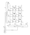
- FIG. 2 is a diagram for explaining a main configuration of the liquid crystal panel shown in FIG.
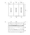
- FIG. 3A is a plan view illustrating a specific configuration example of the picture element provided in the liquid crystal panel
- FIG. 3B is a cross-sectional view illustrating a schematic structure of the picture element.
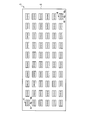
- FIG. 4 is a plan view showing a main configuration of the backlight device shown in FIG.
- FIG. 5 is a block diagram showing a specific configuration example of the controller shown in FIG.
- FIG. 6 is a diagram for explaining an operation example in the liquid crystal display device, and FIGS.
- FIG. 6 (a) to 6 (d) are diagrams for explaining a specific operation in each of four subfield periods. is there.
- FIG. 7 is a diagram for explaining a specific lighting operation of the backlight device.
- FIGS. 7A to 7D show specific lighting periods in the four subfield periods, respectively. It is a figure explaining.
- FIG. 8A is a plan view showing a specific configuration example of picture elements provided in the liquid crystal panel of the liquid crystal display device according to the second embodiment of the present invention, and FIG. It is sectional drawing explaining the schematic structure of the picture element shown to 8 (a).
- FIG. 9 is a diagram for explaining a specific lighting operation of the backlight device of the liquid crystal display device according to the second embodiment of the present invention, and FIGS.
- FIG. 10 is a diagram for explaining a main configuration of a liquid crystal display device according to the third embodiment of the present invention.
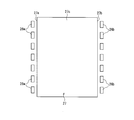
- FIG. 11 is a plan view showing a main configuration of the backlight device shown in FIG.
- FIG. 1 is a diagram for explaining a main configuration of a liquid crystal display device according to a first embodiment of the present invention.
- a liquid crystal display device 1 includes a liquid crystal panel 2 as a display unit for displaying information and a non-display surface side (lower side in the figure) of the liquid crystal panel 2.
- a backlight device 3 as a backlight unit for irradiating illumination light is provided, and the liquid crystal panel 2 and the backlight device 3 are integrated as a transmissive liquid crystal display device 1.
- light emitting diodes 4 as light sources are accommodated in a plurality of chassis 5.
- Each of the plurality of light emitting diodes 4 is disposed so as to face the liquid crystal panel 2 through the diffusion plate 6, the prism sheet 12, and the polarizing sheet 11.
- a liquid crystal layer (described later) included in the liquid crystal panel 2 is connected to a drive circuit 10 through an FPC (Flexible Printed Circuit) 9, and the drive circuit 10 uses the liquid crystal layer as a pixel.
- the unit can be driven.
- An inverter circuit 11 is installed in the vicinity of the drive circuit 10. The inverter circuit 11 is configured to drive and drive the plurality of light emitting diodes 4.
- the liquid crystal display device 1 of the present embodiment is configured to display information by dividing one frame period (1 TV field period) into four subfield periods, as will be described in detail later.
- Each of the four subfield periods is a 1 ⁇ 4 frame period and is configured to have the same time.
- liquid crystal panel 2 and the backlight device 3 according to this embodiment will be described in detail with reference to FIGS.
- FIG. 2 is a diagram for explaining a main configuration of the liquid crystal panel shown in FIG.
- FIG. 3A is a plan view illustrating a specific configuration example of the picture element provided in the liquid crystal panel
- FIG. 3B is a cross-sectional view illustrating a schematic structure of the picture element.
- FIG. 4 is a plan view showing a main configuration of the backlight device shown in FIG.
- FIG. 5 is a block diagram showing a specific configuration example of the controller shown in FIG.
- the liquid crystal display device 1 of the present embodiment is provided with a controller 12 as a control device to which a video signal and a dimming instruction signal are input from the outside (see also FIG. 5). Each drive control of the panel 2 and the backlight apparatus 3 is performed. Further, as shown in FIG. 2, the controller 12 is connected to the gate driver 13 and the source driver 14 of the liquid crystal panel 2 included in the drive circuit 10.
- the gate driver 13 and the source driver 14 are drive circuits that drive a plurality of pixels P provided in the liquid crystal panel 2 in units of pixels.
- the gate driver 13 and the source driver 14 include a plurality of gate lines G1 to GN. (N is an integer of 2 or more) and a plurality of source lines S1 to SM (M is an integer of 2 or more) are connected to each other.
- the gate lines G1 to GN and the source lines S1 to SM are arranged in a matrix, and the regions of the plurality of pixels P are formed in the regions partitioned in the matrix.
- the gate lines G1 to GN are provided for each pixel P, and connected to the gate of the switching element 15 using, for example, a thin film transistor.
- the source of the switching element 15 is connected to each of the source lines S1 to SM.
- a pixel electrode 16 provided for each pixel P is connected to the drain of each switching element 15.
- the common electrode 17 is configured to face the pixel electrode 16 with the liquid crystal layer interposed therebetween.
- a control signal is input from the controller 12 to the source driver 14. Then, the source driver 14 appropriately outputs a voltage signal corresponding to the input control signal to the source lines S1 to SM.
- the gate driver 13 sequentially outputs gate signals for turning on the gates of the corresponding switching elements 15 to the gate lines G1 to GN based on the control signal from the controller 12. Thereby, in the liquid crystal panel 2, in order to display the input image corresponding to the input image signal, the transmittance is changed for each pixel P, and the input image is displayed.
- a picture element having a set of three pixels (n pixels (n is an integer of 3 or more)) that can be mixed in white is provided.
- the picture element of the liquid crystal panel 2 is composed of a red pixel Pr, a green pixel Pg, and a transparent pixel Pt.
- the red pixel Pr, the green pixel Pg, and the transparent pixel Pt are sequentially provided along the source lines S1 to SM. Further, the red pixel Pr and the green pixel Pg constitute (n ⁇ 1) pixels.
- the red pixel Pr and the green pixel Pg are provided with red and green color filters 21r and 21g, respectively, and the transparent pixel Pt is provided with a color filter.
- the liquid crystal panel 2 includes a color filter substrate 18 provided with color filters 21r and 21g, an active matrix substrate 19 provided with the switching element 15 and the like, and these colors.
- the liquid crystal layer 20 sandwiched between the filter substrate 18 and the active matrix substrate 19 is provided, and the red pixel Pr, the green pixel Pg, and the transparent pixel Pt are the left end portion of FIG. It is formed sequentially from the side to the right end side.
- the vertical dimension Py in FIG. 3A is configured to be the same value.
- the horizontal dimensions Pxr, Pxg, and Pxt in FIG. 3A are also set to the same value. That is, in the picture element of the present embodiment, the red pixel Pr, the green pixel Pg, and the transparent pixel Pt are configured to have the same area.
- the red pixel Pr, the green pixel Pg, and the transparent pixel Pt are irradiated with illumination light from the backlight device 3 provided on the active matrix substrate 19 side. Further, as will be described in detail later, the backlight device 3 alternately emits white light and blue light as the illumination light.
- the red pixel Pr, the green pixel Pg, and the transparent pixel Pt are configured to display red, green, and white information, respectively, and blue light is emitted.
- only transparent pixels Pt are configured to display blue information.
- the time for irradiating blue light is set shorter than the time for irradiating white light, and the amount of light transmitted through the red pixel Pr and the green pixel Pg.
- the amount of light transmitted through the transparent pixel Pt is set to substantially the same value (details will be described later).
- the backlight device 3 As illustrated in FIG. 4, in the backlight device 3, a total of 60 light emitting diodes 4 in 6 rows and 10 columns provided in parallel in the horizontal and vertical directions on the display surface of the liquid crystal panel 2 are used. Yes. Further, in the backlight device 3, the light emitting diode 4 is provided so as to face the liquid crystal panel (display unit) 2, thereby constituting a direct type backlight device.
- red, green, and blue light emitting diodes 4r, 4g, and 4b that emit red (R), green (G), and blue (B) light, respectively, are integrated with each of the plurality of light emitting diodes 4.
- the so-called three-in-one (3 in 1) type configured as described above is used. That is, the backlight device 3 uses a plurality of color light sources that can be mixed with white light.
- the red and green light emitting diodes 4r and 4g constitute a plurality of light sources other than the nth light source
- the blue light emitting diode 4g is the first light emitting diode 4g.
- n light sources are formed.
- controller 12 will be specifically described with reference to FIG.
- the controller 12 is input via a panel control unit 22 as a display control unit, an illumination control unit 23 that performs drive control of the backlight device 3, an antenna (not shown), and the like.
- a frame memory 24 configured to store display data in units of frames included in the video signal.
- an ASIC Application Specific Integrated Circuit
- the panel control unit 22 can perform predetermined calculation processing on the display data sequentially stored in the frame memory 24 at high speed. It is like that.
- the panel control unit 22 is provided with an image processing unit 22a and a video signal conversion unit 22b, and drive control of the liquid crystal panel 2 is performed on a pixel basis using the input video signal. .
- the panel control unit 22 determines that each subfield from the input video signal based on illumination light in each subfield period of S (S is an integer of 2 or more), for example, four subfield periods.
- the drive control of the liquid crystal panel 2 is performed by obtaining a video signal in a period.
- the backlight control unit 23 turns on the light emitting diodes 4r, 4g, and 4b (a plurality of light sources) in the four subfield periods, and emits white light as illumination light to the liquid crystal panel 2. And a second lighting period in which the light emitting diode 4b (nth light source) is turned on to emit blue (color other than (n-1)) light as illumination light to the liquid crystal panel 2.
- the lighting driving of the light emitting diodes 4r, 4g, and 4b is controlled so that the subfield periods are alternately performed in two subfield periods.
- the backlight control unit 23 is configured to control the lighting drive of the light emitting diode 4 so that the time of the second lighting period is shorter than the time of the first lighting period.
- the panel control unit 22 operates the red and green pixels Pr, Pg ((n ⁇ 1) pixels) and the transparent pixel Pt during the first lighting period, and during the second lighting period. Then, the transparent pixel Pt is operated.
- the image processing unit 22a is configured to output an instruction signal to the gate driver 13 and the source driver 14 such as the timing signal in accordance with the input video signal. Further, the image processing unit 22a determines the magnitude of the data signal (gradation voltage) in units of pixels based on the video signal after being converted by the video signal conversion unit 22b, and serves as an instruction signal to the source driver 14. Including output.
- the video signal conversion unit 22b is configured to generate each video signal in units of pixels in four subfield periods included in one frame period in which one image is displayed on the liquid crystal panel 2. That is, the video signal converter 22b converts the input video signal into each video signal in four subfield periods based on the input video signal and illumination light in each of the four subfield periods. It is supposed to convert.
- the video signal conversion unit 22b acquires the transmittance data of each pixel from the display data included in the video signal for one frame held in the frame memory 24. Then, the video signal conversion unit 22b uses the acquired transmittance of each pixel in accordance with a predetermined algorithm in consideration of the color of illumination light (that is, white and blue) in the first and second lighting periods. Thus, the transmittances of the corresponding pixels in the four subfield periods are determined. Thereby, in each pixel, the transmittances of the four subfield periods are appropriately changed according to the input video signal and the color of the illumination light from the backlight device 3.
- FIG. 6 is a diagram for explaining an operation example in the liquid crystal display device
- FIGS. 6 (a) to 6 (d) are diagrams for explaining a specific operation in each of four subfield periods. is there.
- FIG. 7 is a diagram for explaining a specific lighting operation of the backlight device.
- FIGS. 7A to 7D show specific lighting periods in the four subfield periods, respectively. It is a figure explaining.
- the first lighting period is performed in the first subfield period of the four subfield periods. That is, in the first subfield period, all the RGB light emitting diodes 4r, 4g, and 4b are turned on, and white light is irradiated from the backlight device 3 to the liquid crystal panel 2 as illumination light.
- all pixels P that is, red and green pixels Pr and Pg and transparent pixels Pt are driven to display information.
- a second lighting period is performed in the second subfield period. That is, in the second subfield period, only the blue light-emitting diode 4b is turned on, and the backlight device 3 irradiates the liquid crystal panel 2 with blue light as illumination light. In the liquid crystal panel 2, only transparent pixels Pt are driven to display information.
- a first lighting period is performed in the third subfield period. That is, in the third subfield period, all the RGB light emitting diodes 4r, 4g, and 4b are turned on, and white light is emitted from the backlight device 3 to the liquid crystal panel 2 as illumination light. In the liquid crystal panel 2, all pixels P, that is, red and green pixels Pr and Pg and transparent pixels Pt are driven to display information.
- the second lighting period is performed in the fourth subfield period. That is, in the fourth subfield period, only the blue light emitting diode 4b is turned on, and the backlight device 3 irradiates the liquid crystal panel 2 with blue light as illumination light. In the liquid crystal panel 2, only transparent pixels Pt are driven to display information.
- the first subfield period is performed between time T1 and time T2, and this subfield period is the first lighting period.
- white light is emitted from the backlight device 3 to the liquid crystal panel 2.
- the second subfield period is performed between time T2 and time T4. Further, in this subfield period, for example, a second lighting period is performed between time T2 and time T3, which is shorter than the time of the period, and blue light is emitted from the backlight device 3 to the liquid crystal panel 2.
- the third subfield period is performed between the time point T4 and the time point T5, and this subfield period is the first lighting period.
- white light is emitted from the backlight device 3 to the liquid crystal panel 2.
- the fourth subfield period is performed between time T5 and time T7. Further, in this subfield period, a second lighting period is performed between time T5 and time T6, which is shorter than the time of the period, and blue light is emitted from the backlight device 3 to the liquid crystal panel 2.
- the time of the first and second lighting periods and the time difference between the first and second lighting periods (that is, the time from the time T3 to the time T4 and the time T6)
- the sum of the time until time T7) is such that the amount of light transmitted through the red pixel Pr and the green pixel Pg and the amount of light transmitted through the transparent pixel Pt are substantially the same in one frame period. It has been established. That is, compared with the blue light transmitted through the transparent pixel Pt, the red and green pixels Pr and Pg absorb light in the color filters 21r and 21g, so that the luminance of the red and green light is reduced. . Therefore, as described above, by adjusting the times of the first and second lighting periods, it is possible to balance the luminance of red, green, and blue light.
- the liquid crystal panel (display unit) 2 is provided with red and green ((n-1) color) color filters 21r and 21g, respectively.
- Green pixels ((n-1) pixels) Pr and Pg and transparent pixels Pt not provided with a color filter are configured as a set of picture elements.
- the backlight device (backlight unit) 3 includes red and green light emitting diodes (a plurality of light sources other than the nth light source) 4r, 4g, and blue (( and a blue light emitting diode (nth light source) 4b that emits light of a color other than (n-1) color).
- the backlight control unit 23 turns on the light-emitting diodes 4r, 4g, and 4b and emits white light as illumination light in the four subfield periods.
- the lighting period and the second lighting period in which the light-emitting diode 4b is turned on to emit blue light as illumination light are alternately performed in two consecutive sub-feel periods of four sub-field periods.
- the lighting drive of the light emitting diodes 4r, 4g, 4b is controlled.
- the panel control unit (display control unit) 22 operates the red and green pixels Pr and Pg and the transparent pixel Pt during the first lighting period, and the transparent pixel Pt during the second lighting period.
- a liquid crystal display device (display) excellent in display quality that can suppress the color breaking phenomenon even when one frame period is divided into a plurality of subfield periods. Apparatus) 1 can be configured.
- the transparent pixel Pt since the transparent pixel Pt is provided, it is possible to improve the utilization efficiency of the light of each color of white and blue, and the brightness of each color of white and blue can be easily achieved. Can be increased.
- the transparent pixel Pt performs the display operation than the time of the first lighting period in which the red and green pixels Pr and Pg and the transparent pixel Pt perform the display operation.
- the second lighting period is set to be short.
- the amount of light transmitted through the red and green pixels Pr and Pg and the amount of light transmitted through the transparent pixel Pt can be set to substantially the same value.
- the balance of the display color by the green pixels Pr and Pg and the transparent pixel Pt can be made appropriate, and the display quality can be reliably prevented from deteriorating.
- FIG. 8A is a plan view showing a specific configuration example of picture elements provided in the liquid crystal panel of the liquid crystal display device according to the second embodiment of the present invention, and FIG. It is sectional drawing explaining the schematic structure of the picture element shown to 8 (a).
- FIG. 9 is a diagram for explaining a specific lighting operation of the backlight device of the liquid crystal display device according to the second embodiment of the present invention, and FIGS. It is a figure explaining the concrete lighting period in the number of subfield periods.
- the main difference between the present embodiment and the first embodiment is that the time of the first and second lighting periods is set to the same time, and the red and green pixels in the picture element. The point is that the area of the transparent pixel is made smaller than the area.
- symbol is attached
- the area of the transparent pixel Pt ′ is that of the red and green pixels Pr ′ and Pg ′. It is configured to be smaller than the area.
- the vertical dimension Py ′ in FIG. 8A is configured to have the same value.
- the dimension Pxt ′ in the same direction is smaller than the dimensions Pxr ′ and Pxg ′ in the left-right direction in FIG. Is set to That is, the red and green color filters 21r 'and 21g' of the present embodiment have smaller areas than the color filters 21r and 21g shown in Fig. 3B.
- the area of the transparent pixel Pt ′ is configured to be smaller than the areas of the red and green pixels Pr ′ and Pg ′, the amount of light transmitted through the transparent pixel Pt ′. And the amount of light transmitted through the red and green pixels Pr ′ and Pg ′ can be set to substantially the same value.
- the backlight control unit 23 sets the first and second lighting periods to the same time. That is, as shown in FIG. 9A, the first subfield period is performed between time T8 and time T9, and this subfield period is the first lighting period. Between T8 and time T9, white light is emitted from the backlight device 3 to the liquid crystal panel 2.
- the second subfield period is performed between time T9 and time T10. Since the subfield period is the second lighting period, blue light is emitted from the backlight device 3 to the liquid crystal panel 2 between the time T9 and the time T10.
- the third subfield period is performed between time T10 and time T11. Since this subfield period is the first lighting period, From T10 to time T11, white light is emitted from the backlight device 3 to the liquid crystal panel 2.
- the fourth subfield period is performed between time T11 and time T12. Further, since this subfield period is the second lighting period, blue light is emitted from the backlight device 3 to the liquid crystal panel 2 between the time T11 and the time T12.
- the present embodiment can achieve the same operations and effects as the first embodiment.
- the area of the transparent pixel Pt ′ is smaller than the areas of the red and green pixels Pr ′ and Pg ′.
- the amount of light can be set to substantially the same value, the display color balance of the red and green pixels Pr ′ and Pg ′ and the transparent pixel Pt ′ can be made appropriate, and the display quality is lowered. Can be surely prevented.
- FIG. 10 is a diagram for explaining a main configuration of a liquid crystal display device according to the third embodiment of the present invention.
- FIG. 11 is a plan view showing a main configuration of the backlight device shown in FIG. In the figure, the main difference between the present embodiment and the first embodiment is that an edge light type backlight device having a light guide plate is used.
- symbol is attached
- the liquid crystal display device 1 of the present embodiment uses an edge light type backlight device (backlight unit) 3.
- the backlight device 3 includes a light guide plate 27 into which white light from the white light emitting diode 26w and blue light from the blue light emitting diode 26b are incident.
- the light from the light guide plate 27 is irradiated to the liquid crystal panel 2 through the diffusion sheet 25, the prism sheet 12, and the polarizing sheet 11.
- seven light emitting diodes 26 w are provided on one side of the long side of the light guide plate 27 so as to face each other.
- a light incident surface 27a for receiving white light from 26w is configured.
- seven light emitting diodes 26b are provided on the other side surface on the long side of the light guide plate 27 so that the side surfaces receive blue light from the light emitting diodes 26b.
- a surface 27b is formed.
- the light guide plate 27 in the first lighting period included in the subfield period, only white light from the light emitting diode 26w is incident, and illumination light is emitted from the entire light emitting surface 27c to the liquid crystal panel 2 side. It is designed to emit white light.
- the blue light from the light emitting diode 26b is incident during the second lighting period included in the subfield period, and as illumination light from the entire light emitting surface 27c to the liquid crystal panel 2 side. It is designed to emit blue light.
- the present embodiment can achieve the same operations and effects as the first embodiment.
- the liquid crystal panel display unit
- the liquid crystal The panel 2 is irradiated with illumination light from an edge-light type backlight device (backlight unit) 3.
- the display device of the present invention is not limited to this, and information is obtained using light of a light source.
- the present invention can be applied to various non-light emitting display devices for display.
- the display device of the present invention can be suitably used for a transflective liquid crystal display device or a projection display device such as a rear projection using the liquid crystal panel as a light valve.
- the display unit can be applied to various display devices using other display elements such as a display element using the electrowetting phenomenon.
- the light source of the present invention is not limited to this, for example, a discharge tube such as a cold cathode fluorescent tube or a hot cathode fluorescent tube, an organic Light emitting devices such as EL (Electronic Luminescence) and inorganic EL elements, or light emitting devices such as PDP (Plasma Display Panel) can also be used as the light source.
- a discharge tube such as a cold cathode fluorescent tube or a hot cathode fluorescent tube
- an organic Light emitting devices such as EL (Electronic Luminescence) and inorganic EL elements
- PDP Plasma Display Panel
- a light-emitting diode as a light source as in the above embodiments because an energy-saving and environment-friendly display device can be easily configured.
- one frame period is divided into four subfield periods
- one frame period is divided into S (S is 2 or more).
- S is 2 or more.
- the present invention can be applied to a plurality of continuous subfield periods constituting one frame period (one TV field period).
- red and green pixels provided with red and green color filters are used as (n ⁇ 1) pixels, and red and green light sources other than the nth light source are used.
- red and green light emitting diodes that emit green light are used, and a blue light emitting diode that emits blue light is used as the nth light source.
- the present invention is not limited to this, and in the display unit, n pixels (n is an integer of 3 or more) that can be mixed with white are provided, and (n-1) color filters are provided.
- (N-1) pixels each having a color filter and transparent pixels not having a color filter are configured as a set of picture elements, and at least (n-1) colors other than those in the backlight unit.
- the some light source containing the nth light source which light-emits the color light.
- red and blue pixels provided with red and blue color filters are used, and a plurality of light sources other than the nth light source emit red and blue light, respectively.
- a green light source that emits green light may be used as the nth light source.
- the red, green, and blue light emitting diodes that emit red (R), green (G), and blue (B) light are integrated.
- a so-called three-in-one (3 in 1) type light emitting diode is used, and during the first lighting period, all red, green, and blue light emitting diodes are turned on to emit white light as illumination light.
- the second lighting period the configuration in which only the blue light-emitting diode is turned on to emit blue light as illumination light has been described.
- the present invention is not limited to this.
- white light emitting diodes and blue light emitting diodes are alternately arranged inside the chassis, and white and blue light emitting diodes are displayed in the first and second lighting periods.
- the light-emitting diodes may be turned on.
- a blue pixel provided with a blue color filter, a yellow pixel provided with a yellow color filter other than RGB, and a transparent pixel are used, and red, green, Alternatively, the red, green, and white light sources that respectively emit white light may be turned on in three consecutive subfield periods.
- red and green pixels are used, red and green light sources are used as the first to (n-1) light sources, and blue light sources are used as the nth light source.
- red and green color filters it is possible to perform full color display without using a blue color filter with low transmittance, and high luminance with excellent light use efficiency of the light source. It is preferable in that a simple display device can be easily configured.
- the difference between the transmittance of (n ⁇ 1) pixels and the transmittance of transparent pixels is substantially zero.
- the pixel and the transparent pixel are not limited as long as they are adjusted. That is, in the present invention, (n ⁇ 1) pixels and transparent pixels are adjusted so that the difference from the transmittance is substantially zero, thereby transmitting (n ⁇ 1) pixels.
- the amount of light and the amount of light transmitted through the transparent pixels can be made substantially the same value, and the balance of display colors by these (n-1) pixels and the transparent pixels can be made appropriate. As long as the display quality can be prevented from deteriorating, it is sufficient.
- the first and second embodiments may be combined.
- the present invention is useful for a display device excellent in display quality that can suppress the color breaking phenomenon even when one frame period is divided into a plurality of subfield periods.
- Liquid crystal display device Liquid crystal panel (display unit) 3 Backlight device (backlight part) 4 Light emitting diode (light source) 4r red light emitting diode (light source) 4g Green light emitting diode (light source) 4b Blue light emitting diode ((nth) light source) 21r, 21r 'red color filters ((n-1) color filters) 21g, 21g 'green color filters ((n-1) color filters) 22 Panel controller (display controller) 23 Backlight controller (backlight controller) 26w white light emitting diode (light source) 26b Blue light emitting diode ((nth) light source) 27 Light guide plate Pr, Pr ′ Red pixels ((n ⁇ 1) pixels, picture elements) Pg, Pg ′ Green pixels ((n ⁇ 1) pixels, picture elements) Pt, Pt 'Transparent pixels (picture elements)
Landscapes
- Engineering & Computer Science (AREA)
- Physics & Mathematics (AREA)
- General Physics & Mathematics (AREA)
- Theoretical Computer Science (AREA)
- Computer Hardware Design (AREA)
- Crystallography & Structural Chemistry (AREA)
- Chemical & Material Sciences (AREA)
- Nonlinear Science (AREA)
- Mathematical Physics (AREA)
- Optics & Photonics (AREA)
- Liquid Crystal Display Device Control (AREA)
- Liquid Crystal (AREA)
- Control Of Indicators Other Than Cathode Ray Tubes (AREA)
Abstract
液晶パネル(表示部)(2)と、バックライト装置(バックライト部)(3)を備えるとともに、1フレーム期間を4個のサブフィールド期間に分割して情報表示を行う液晶表示装置(1)において、バックライト制御部(23)は、白色の光を発光する第1の点灯期間と、青色の光を発光する第2の点灯期間が、連続する2個のサブフィール期間で交互に行われるように、発光ダイオード(4、4b)の点灯駆動を制御する。また、パネル制御部(表示制御部)(22)は、第1の点灯期間の間では赤色の画素(Pr)、緑色の画素(Pg)、及び透明な画素(Pt)を動作させ、第2の点灯期間の間では透明な画素(Pt)を動作させる。
Description
本発明は、表示装置、特に液晶表示装置などの非発光型の表示装置に関する。
近年、表示装置には、文字や画像などの情報を表示する表示部と、この表示部に対し所定の照明光を照射するバックライト部を有する、いわゆる非発光型の表示装置が実用化されてきている。また、このような表示装置では、液晶表示装置に代表されるように、在来のブラウン管に比べて薄型、軽量などの特長を有するフラットパネルディスプレイとして、テレビ受信装置、モニター、携帯電話などに幅広く利用されている。
また、上記のような従来の表示装置には、例えば下記特許文献1に記載されているように、カラーフィルターが設けられていない表示部に対し、例えば赤色(R)、緑色(G)、及び青色(B)の3色の発光ダイオード(LED)を光源として用い、各色のLEDを順次点滅させることにより、1つのフレーム期間において赤色のみの画像、緑色のみの画像、青色のみの画像を順に表示する駆動方式、いわゆる、フィールドシーケンシャル駆動方式によって、カラー表示を行うことが提案されている。
具体的にいえば、上述の従来の表示装置では、エレクトロウェッティング現象によって光源からの光に対しシャッターの役割を果たす光シャッターを画素単位に設けた表示パネルを表示部として用いていた。また、この従来の表示装置では、1つのフレーム期間毎に、赤色、緑色、青色、及び黒色の光、または赤色、黒色、緑色、黒色、青色、及び黒色の光を順次表示部に出射して、1つのフレーム期間において赤色、緑色、青色の画像順次表示していた。
しかしながら、上記のような従来の表示装置では、1つのフレーム期間を複数のサブフィールド期間に分割して、赤色、緑色、及び青色の各色の画像を高速に切り替えてカラー表示を行っていたので、動画表示を行った場合などにおいて、表示画像の色が分離して見えてしまうという、カラーブレーキング(色割れ)現象を生じることがあった。この結果、従来の表示装置では、1つのフレーム期間を複数のサブフィールド期間に分割したときに、表示品位が低下するという問題点を発生した。
上記の課題を鑑み、本発明は、1つのフレーム期間を複数のサブフィールド期間に分割したときでも、カラーブレーキング現象を抑制することができる表示品位に優れた表示装置を提供することを目的とする。
上記の目的を達成するために、本発明にかかる表示装置は、白色に混色可能なn個(nは、3以上の整数)の画素を1組とする絵素が設けられて、情報を表示する表示部と、前記表示部に対して照明光を照射するバックライト部を有する表示装置であって、
入力された映像信号を使用して、前記表示部の駆動制御を画素単位に行うとともに、1フレーム期間をS個(Sは、2以上の整数)のサブフィールド期間に分割して、前記表示部にて情報表示を行わせる表示制御部と、
前記バックライト部の駆動制御を行うバックライト制御部を備え、
前記表示部では、前記絵素として、(n-1)色のカラーフィルターがそれぞれ設けられた(n-1)個の画素、及びカラーフィルターが設けられていない透明な画素が用いられ、
前記バックライト部には、少なくとも前記(n-1)色以外の色の光を発光する第nの光源を含む複数の光源が設けられ、
前記バックライト制御部は、前記S個のサブフィールド期間において、前記光源を点灯して前記照明光として白色の光を発光する第1の点灯期間と、前記第nの光源を点灯して前記照明光として前記(n-1)色以外の色の光を発光する第2の点灯期間が、前記S個のサブフィールド期間の連続する2個のサブフィール期間で交互に行われるように、前記光源の点灯駆動を制御し、
前記表示制御部は、前記第1の点灯期間の間では前記(n-1)個の画素及び前記透明な画素を動作させ、前記第2の点灯期間の間では前記透明な画素を動作させることを特徴とするものである。
入力された映像信号を使用して、前記表示部の駆動制御を画素単位に行うとともに、1フレーム期間をS個(Sは、2以上の整数)のサブフィールド期間に分割して、前記表示部にて情報表示を行わせる表示制御部と、
前記バックライト部の駆動制御を行うバックライト制御部を備え、
前記表示部では、前記絵素として、(n-1)色のカラーフィルターがそれぞれ設けられた(n-1)個の画素、及びカラーフィルターが設けられていない透明な画素が用いられ、
前記バックライト部には、少なくとも前記(n-1)色以外の色の光を発光する第nの光源を含む複数の光源が設けられ、
前記バックライト制御部は、前記S個のサブフィールド期間において、前記光源を点灯して前記照明光として白色の光を発光する第1の点灯期間と、前記第nの光源を点灯して前記照明光として前記(n-1)色以外の色の光を発光する第2の点灯期間が、前記S個のサブフィールド期間の連続する2個のサブフィール期間で交互に行われるように、前記光源の点灯駆動を制御し、
前記表示制御部は、前記第1の点灯期間の間では前記(n-1)個の画素及び前記透明な画素を動作させ、前記第2の点灯期間の間では前記透明な画素を動作させることを特徴とするものである。
上記のように構成された表示装置では、表示部において、(n-1)色のカラーフィルターがそれぞれ設けられた(n-1)個の画素、及びカラーフィルターが設けられていない透明な画素が1組の絵素として構成されている。また、バックライト部には、少なくとも(n-1)色以外の色の光を発光する第nの光源を含む複数の光源が設けられている。また、バックライト制御部は、S個のサブフィールド期間において、光源を点灯して照明光として白色の光を発光する第1の点灯期間と、第nの光源を点灯して照明光として(n-1)色以外の色の光を発光する第2の点灯期間が、S個のサブフィールド期間の連続する2個のサブフィール期間で交互に行われるように、光源の点灯駆動を制御している。また、表示制御部は、第1の点灯期間の間では(n-1)個の画素及び透明な画素を動作させ、第2の点灯期間の間では透明な画素を動作させる。これにより、上記従来例と異なり、1つのフレーム期間を複数のサブフィールド期間に分割したときでも、カラーブレーキング現象を抑制することができる表示品位に優れた表示装置を構成することができる。
また、上記表示装置において、前記絵素では、前記(n-1)個の画素の透過率と、前記透明な画素の透過率との差が実質的に零となるように、当該(n-1)個の画素及び透明な画素は調整されていることが好ましい。
この場合、(n-1)個の画素を透過する光量と、透明な画素を透過する光量とを実質的に同じ値とすることができ、これら(n-1)個の画素と透明な画素による表示色のバランスを適切なものとすることが可能となって、表示品位が低下するのを防ぐことができる。
また、上記表示装置において、前記絵素では、前記(n-1)個の画素及び前記透明な画素が表示動作を行う前記第1の点灯期間の時間よりも、前記透明な画素が表示動作を行う前記第2の点灯期間の時間が短く設定されてもよい。
この場合、第1及び第2の点灯期間の各時間を調整することにより、(n-1)個の画素と透明な画素による表示色のバランスを適切なものとすることができ、表示品位が低下するのを確実に防ぐことができる。
また、上記表示装置において、前記絵素では、前記(n-1)個の画素の面積よりも、前記透明な画素の面積が小さくされていることが好ましい。
この場合、(n-1)個の画素及び透明な画素の面積を調整することにより、バックライト制御部での制御動作を複雑なものとすることなく、(n-1)個の画素と透明な画素による表示色のバランスを適切なものとすることができ、表示品位が低下するのを確実に防ぐことができる。
また、上記表示装置において、前記絵素では、前記(n-1)個の画素として、赤色及び緑色のカラーフィルターがそれぞれ設けられた赤色及び緑色の画素が用いられ、
前記バックライト部では、前記第nの光源以外の前記複数の光源として、赤色及び緑色の光をそれぞれ発光する赤色及び緑色の光源が用いられ、かつ、前記第nの光源として、青色の光を発光する青色の光源が用いられていることが好ましい。
前記バックライト部では、前記第nの光源以外の前記複数の光源として、赤色及び緑色の光をそれぞれ発光する赤色及び緑色の光源が用いられ、かつ、前記第nの光源として、青色の光を発光する青色の光源が用いられていることが好ましい。
この場合、赤色及び緑色のカラーフィルターに比べて、透過率の低い青色のカラーフィルターを用いることなく、フルカラー表示を行うことが可能となり、光源の光利用効率に優れた高輝度な表示装置を容易に構成することができる。
また、上記表示装置において、前記表示部として、液晶パネルが用いられてもよい。
この場合、1つのフレーム期間を複数のサブフィールド期間に分割したときでも、カラーブレーキング現象を抑制することができる表示品位に優れた液晶表示装置を構成することができる。
また、上記表示装置において、前記バックライト部では、前記光源が前記表示部に対向するように設けられてもよい。
この場合、表示部に対して、直下型のバックライト部からの照明光が照射される。
また、上記表示装置において、前記バックライト部には、前記光源からの光が入光されるとともに、入光した光を前記表示部に出射する導光板が設けられてもよい。
この場合、表示部に対して、エッジライト型のバックライト部からの照明光が照射される。
また、上記表示装置において、前記光源として、発光ダイオードが用いられていることが好ましい。
この場合、省エネルギーで環境に優しい表示装置を容易に構成することができる。
本発明によれば、1つのフレーム期間を複数のサブフィールド期間に分割したときでも、カラーブレーキング現象を抑制することができる表示品位に優れた表示装置を提供することが可能となる。
以下、本発明の表示装置の好ましい実施形態について、図面を参照しながら説明する。なお、以下の説明では、本発明を透過型の液晶表示装置に適用した場合を例示して説明する。また、各図中の構成部材の寸法は、実際の構成部材の寸法及び各構成部材の寸法比率等を忠実に表したものではない。
[第1の実施形態]
図1は、本発明の第1の実施形態にかかる液晶表示装置の要部構成を説明する図である。図1において、液晶表示装置1には、情報を表示する表示部としての液晶パネル2と、液晶パネル2の非表示面側(図の下側)に配置されて、当該液晶パネル2に対して照明光を照射するバックライト部としてのバックライト装置3とが設けられており、これらの液晶パネル2とバックライト装置3とが透過型の液晶表示装置1として一体化されている。
図1は、本発明の第1の実施形態にかかる液晶表示装置の要部構成を説明する図である。図1において、液晶表示装置1には、情報を表示する表示部としての液晶パネル2と、液晶パネル2の非表示面側(図の下側)に配置されて、当該液晶パネル2に対して照明光を照射するバックライト部としてのバックライト装置3とが設けられており、これらの液晶パネル2とバックライト装置3とが透過型の液晶表示装置1として一体化されている。
バックライト装置3では、後に詳述するように、光源としての発光ダイオード4が複数シャーシ5の内部に収容されている。また、これらの複数の各発光ダイオード4は、拡散板6、プリズムシート12、及び偏光シート11を介して、液晶パネル2に対向するように設置されている。
また、液晶表示装置1では、液晶パネル2に含まれた後述の液晶層がFPC(Flexible Printed Circuit)9を介在させて駆動回路10に接続されており、当該駆動回路10が上記液晶層を画素単位に駆動可能に構成されている。また、駆動回路10の近傍には、インバータ回路11が設置されている。このインバータ回路11は、複数の発光ダイオード4を点灯駆動するように構成されている。
また、本実施形態の液晶表示装置1では、後に詳述するように、1フレーム期間(1TVフィールド期間)が4個のサブフィールド期間に分割されて、情報表示を行うように構成されている。尚、4個の各サブフィールド期間は1/4フレーム期間であり、互いに同じ時間となるように構成されている。
次に、図2~図5も参照して、本実施形態の液晶パネル2及びバックライト装置3について具体的に説明する。
図2は、図1に示した液晶パネルの要部構成を説明する図である。図3(a)は、上記液晶パネルに設けられた絵素の具体的な構成例を示す平面図であり、図3(b)は、上記絵素の概略構造を説明する断面図である。図4は、図1に示したバックライト装置の要部構成を示す平面図である。図5は、図2に示したコントローラの具体的な構成例を示すブロック図である。
まず図2及び図3を用いて、本実施形態の液晶パネル2及び液晶パネル2に設けられた絵素の構造について具体的に説明する。
図2において、本実施形態の液晶表示装置1には、外部から映像信号や調光指示信号が入力される制御装置としてのコントローラ12が設けられており(図5も参照)、コントローラ12が液晶パネル2及びバックライト装置3の各駆動制御を行うようになっている。また、コントローラ12は、図2に示すように、上記駆動回路10に含まれた液晶パネル2のゲートドライバ13及びソースドライバ14に接続されている。
これらのゲートドライバ13及びソースドライバ14は、液晶パネル2に設けられた複数の画素Pを画素単位に駆動する駆動回路であり、ゲートドライバ13及びソースドライバ14には、複数のゲート線G1~GN(Nは、2以上の整数)及び複数のソース線S1~SM(Mは、2以上の整数)がそれぞれ接続されている。これらのゲート線G1~GN及びソース線S1~SMは、マトリクス状に配列されており、当該マトリクス状に区画された各領域には、上記複数の各画素Pの領域が形成されている。
また、各ゲート線G1~GNには、画素P毎に設けられるとともに、例えば薄膜トランジスタ(Thin Film Transistor)を用いたスイッチング素子15のゲートが接続されている。一方、各ソース線S1~SMには、スイッチング素子15のソースが接続されている。また、各スイッチング素子15のドレインには、画素P毎に設けられた画素電極16が接続されている。また、各画素Pでは、共通電極17が上記液晶層を間に挟んだ状態で画素電極16に対向するよう構成されている。
また、液晶パネル2では、ソースドライバ14に対して、上記コントローラ12から制御信号が入力されるようになっている。そして、ソースドライバ14は、入力した制御信号に応じた電圧信号をソース線S1~SMに対して適宜出力する。また、ゲートドライバ13は、コントローラ12からの制御信号を基にゲート線G1~GNに対して、対応するスイッチング素子15のゲートをオン状態にするゲート信号を順次出力する。これにより、液晶パネル2では、入力された画像信号に対応する入力画像の表示を行うために、画素P毎に透過率が変更され、当該入力画像が表示される。
また、本実施形態の液晶パネル2では、白色に混色可能な3個の画素(n個の画素(nは、3以上の整数))を1組とする絵素が設けられている。具体的にいえば、図3(a)に示すように、液晶パネル2の絵素は、赤色の画素Pr、緑色の画素Pg、及び透明な画素Ptにより、構成されている。また、これら赤色の画素Pr、緑色の画素Pg、及び透明な画素Ptは、上記ソース線S1~SMに沿って順次設けられている。また、赤色の画素Pr及び緑色の画素Pgは、(n-1)個の画素を構成している。
また、図3(b)に示すように、赤色の画素Pr及び緑色の画素Pgには、それぞれ赤色及び緑色のカラーフィルター21r、21gが設けられ、透明な画素Ptには、カラーフィルターが設けられていない。すなわち、同図3(b)に示すように、液晶パネル2は、カラーフィルター21r、21gが設けられたカラーフィルター基板18と、上記スイッチング素子15などが設けられたアクティブマトリクス基板19と、これらカラーフィルター基板18とアクティブマトリクス基板19との間に狭持された上記液晶層20を備えており、赤色の画素Pr、緑色の画素Pg、及び透明な画素Ptが同図3(b)の左端部側から右端部側に順次形成されている。
また、赤色の画素Pr、緑色の画素Pg、及び透明な画素Ptでは、図3(a)の上下方向の寸法Pyは同じ値に構成されている。また、赤色の画素Pr、緑色の画素Pg、及び透明な画素Ptでは、図3(a)の左右方向の寸法Pxr、Pxg、及びPxtも同じ値に構成されている。つまり、本実施形態の絵素では、赤色の画素Pr、緑色の画素Pg、及び透明な画素Ptは互いに同じ面積を有するように構成されている。
また、赤色の画素Pr、緑色の画素Pg、及び透明な画素Ptでは、アクティブマトリクス基板19側に設けられたバックライト装置3から照明光が照射されるようになっている。さらに、バックライト装置3は、後に詳述するように、上記照明光として、白色の光と、青色の光を交互に照射するようになっている。そして、白色の光が照射された場合には、赤色の画素Pr、緑色の画素Pg、及び透明な画素Ptはそれぞれ赤色、緑色、及び白色の情報表示を行うように構成され、青色の光が照射された場合には、透明な画素Ptだけが青色の情報表示を行うように構成されている。
また、本実施形態の液晶パネル2では、白色の光が照射される時間よりも、青色の光が照射される時間が短く設定されており、赤色の画素Pr及び緑色の画素Pgを透過する光量と、透明な画素Ptを透過する光量とを実質的に同じ値とするようになっている(詳細は後述。)。
次に、図4を用いて、本実施形態のバックライト装置3について具体的に説明する。
図4に例示するように、バックライト装置3では、液晶パネル2の表示面での横方向及び縦方向にそれぞれ平行に設けられる6行及び10列、合計60個の発光ダイオード4が使用されている。また、バックライト装置3では、発光ダイオード4が液晶パネル(表示部)2に対向するように設けられており、直下型のバックライト装置を構成している。
また、複数の各発光ダイオード4には、例えば赤色(R)、緑色(G)、及び青色(B)の光をそれぞれ発光する赤色、緑色、及び青色の発光ダイオード4r、4g、4bを一体的に構成した、いわゆるスリーインワン(3in1)タイプが使用されている。すなわち、バックライト装置3では、白色の光に混色可能な複数色の光源が用いられている。また、これら赤色、緑色、及び青色の発光ダイオード4r、4g、4bのうち、赤色及び緑色の発光ダイオード4r、4gは第nの光源以外の複数の光源を構成し、青色の発光ダイオード4gは第nの光源を構成している。そして、バックライト装置3では、後に詳述するように、1フレーム期間において、照明光として白色の光を発光する第1の点灯期間と、照明光として上記(n-1)色以外の色、つまり青色の光を発光する第2の点灯期間が、4個のサブフィールド期間の連続する2個のサブフィール期間で交互に行われるようになっている。
次に、図5を用いて、コントローラ12について具体的に説明する。
コントローラ12には、図5に示すように、表示制御部としてのパネル制御部22と、バックライト装置3の駆動制御を行う照明制御部23と、アンテナ(図示せず)などを介して入力された映像信号に含まれたフレーム単位の表示データを記憶可能に構成されたフレームメモリ24とが設けられている。このパネル制御部22には、例えばASIC(Application Specific Integrated Circuit)が用いられており、パネル制御部22が、フレームメモリ24に逐次格納される上記表示データに対し、所定の演算処理を高速に行えるようになっている。
また、パネル制御部22には、画像処理部22aと映像信号変換部22bが設けられており、入力された映像信号を用いて、液晶パネル2の駆動制御を画素単位に行うようになっている。また、パネル制御部22は、S個(Sは、2以上の整数)、例えば4個のサブフィールド期間の各サブフィールド期間での照明光に基づいて、入力された映像信号から当該各サブフィールド期間での映像信号を求めて、液晶パネル2の駆動制御を行うように構成されている。
バックライト制御部23は、4個のサブフィールド期間において、発光ダイオード4r、4g、4b(複数の光源)を点灯して、液晶パネル2への照明光として白色の光を発光する第1の点灯期間と、発光ダイオード4b(第nの光源)を点灯して、液晶パネル2への照明光として青色((n-1)色以外の色)の光を発光する第2の点灯期間が、4個のサブフィールド期間の連続する2個のサブフィール期間で交互に行われるように、発光ダイオード4r、4g、4bの点灯駆動を制御するようになっている。
また、バックライト制御部23は、上記第1の点灯期間の時間よりも、第2の点灯期間の時間が短くなるように、発光ダイオード4の点灯駆動を制御するよう構成されている。
そして、パネル制御部22は、第1の点灯期間の間では赤色及び緑色の画素Pr、Pg((n-1)個の画素)及び透明な画素Ptを動作させ、第2の点灯期間の間では透明な画素Ptを動作させるようになっている。
画像処理部22aは、入力された映像信号に応じて、上記タイミング信号等のゲートドライバ13及びソースドライバ14への指示信号を出力するように構成されている。また、画像処理部22aは、映像信号変換部22bによって変換された後の映像信号を基に上記データ信号(階調電圧)の大きさを画素単位に定めて、ソースドライバ14への指示信号に含めて出力するようになっている。
映像信号変換部22bは、液晶パネル2において1画像を表示する1フレーム期間に含まれた4個のサブフィールド期間での各映像信号を画素単位に生成するように構成されている。すなわち、映像信号変換部22bは、入力された映像信号を、当該入力された映像信号と4個の各サブフィールド期間での照明光に基づいて、4個のサブフィールド期間での各映像信号に変換するようになっている。
具体的には、映像信号変換部22bは、フレームメモリ24に保持された1フレーム分の映像信号に含まれた表示データから各画素の透過率のデータを取得する。そして、映像信号変換部22bは、上記第1及び第2の点灯期間での照明光の色(すなわち、白色及び青色)を考慮した、所定のアルゴリズムにしたがって、取得した各画素の透過率を使用して、対応する画素の4個の各サブフィールド期間での各透過率を決定するようになっている。これにより、各画素では、4個のサブフィールド期間の各透過率が入力された映像信号とバックライト装置3からの照明光の色に応じて、適切に変更される。
続いて、図6及び図7も参照して、本実施形態の液晶表示装置1の動作について具体的に説明する。
図6は、上記液晶表示装置での動作例を説明する図であり、図6(a)~図6(d)は、それぞれ4個のサブフィールド期間での具体的な動作を説明する図である。図7は、上記バックライト装置の具体的な点灯動作を説明する図であり、図7(a)~図7(d)は、それぞれ上記4個のサブフィールド期間での具体的な点灯期間を説明する図である。
図6(a)に示すように、本実施形態の液晶表示装置1では、4個のサブフィールド期間の1番目のサブフィールド期間においては第1の点灯期間が行われる。すなわち、この1番目のサブフィールド期間では、RGBの全ての発光ダイオード4r、4g、4bが点灯されて、バックライト装置3から照明光として白色の光が液晶パネル2に照射される。また、液晶パネル2では、全ての画素P、つまり赤色及び緑色の画素Pr、Pgと透明な画素Ptが駆動されて、情報表示を行うようになっている。
次に、図6(b)に示すように、2番目のサブフィールド期間においては第2の点灯期間が行われる。すなわち、この2番目のサブフィールド期間では、青色の発光ダイオード4bだけが点灯されて、バックライト装置3から照明光として青色の光が液晶パネル2に照射される。また、液晶パネル2では、透明な画素Ptだけが駆動されて、情報表示を行うようになっている。
次に、図6(c)に示すように、3番目のサブフィールド期間においては第1の点灯期間が行われる。すなわち、この3番目のサブフィールド期間では、RGBの全ての発光ダイオード4r、4g、4bが点灯されて、バックライト装置3から照明光として白色の光が液晶パネル2に照射される。また、液晶パネル2では、全ての画素P、つまり赤色及び緑色の画素Pr、Pgと透明な画素Ptが駆動されて、情報表示を行うようになっている。
次に、図6(d)に示すように、4番目のサブフィールド期間においては第2の点灯期間が行われる。すなわち、この4番目のサブフィールド期間では、青色の発光ダイオード4bだけが点灯されて、バックライト装置3から照明光として青色の光が液晶パネル2に照射される。また、液晶パネル2では、透明な画素Ptだけが駆動されて、情報表示を行うようになっている。
また、図7(a)に示すように、1番目のサブフィールド期間は時点T1から時点T2の間で行われるようになっており、このサブフィールド期間は第1の点灯期間であるので、時点T1から時点T2の間では、バックライト装置3から白色の光が液晶パネル2に出射される。
また、図7(b)に示すように、2番目のサブフィールド期間は時点T2から時点T4の間で行われるようになっている。また、このサブフィールド期間では、その期間の時間よりも短い、例えば時点T2から時点T3の間で第2の点灯期間が行われて、バックライト装置3から青色の光が液晶パネル2に出射される。
また、図7(c)に示すように、3番目のサブフィールド期間は時点T4から時点T5の間で行われるようになっており、このサブフィールド期間は第1の点灯期間であるので、時点T4から時点T5の間では、バックライト装置3から白色の光が液晶パネル2に出射される。
また、図7(d)に示すように、4番目のサブフィールド期間は時点T5から時点T7の間で行われるようになっている。また、このサブフィールド期間では、その期間の時間よりも短い、例えば時点T5から時点T6の間で第2の点灯期間が行われて、バックライト装置3から青色の光が液晶パネル2に出射される。
また、4個のサブフィールド期間において、第1及び第2の点灯期間の時間、及びこれら第1及び第2の点灯期間の時間差の時間(つまり、時点T3から時点T4までの時間と時点T6から時点T7までの時間の和)は、1フレーム期間において、赤色の画素Pr及び緑色の画素Pgを透過する光量と、透明な画素Ptを透過する光量とが実質的に同じ値となるように、定められている。すなわち、透明な画素Ptを透過する青色の光に比べて、赤色及び緑色の画素Pr、Pgではカラーフィルター21r、21gにて、光が吸収されるため、赤色及び緑色の光に輝度低下が生じる。それ故、上記のように、第1及び第2の点灯期間の時間を調整することにより、赤色、緑色、及び青色の光について輝度バランスを取ることができる。
以上のように構成された本実施形態の液晶表示装置1では、液晶パネル(表示部)2において、赤色及び緑色((n-1)色)のカラーフィルター21r、21gがそれぞれ設けられた赤色及び緑色の画素((n-1)個の画素)Pr、Pg、及びカラーフィルターが設けられていない透明な画素Ptが1組の絵素として構成されている。また、バックライト装置(バックライト部)3には、赤色及び緑色の各色の光をそれぞれ発光する赤色及び緑色の発光ダイオード(第nの光源以外の複数の光源)4r、4gと、青色((n-1)色以外の色)の光を発光する青色の発光ダイオード(第nの光源)4bとが設けられている。
また、本実施形態の液晶表示装置1では、バックライト制御部23は、4個のサブフィールド期間において、発光ダイオード4r、4g、4bを点灯して照明光として白色の光を発光する第1の点灯期間と、発光ダイオード4bを点灯して照明光として青色の光を発光する第2の点灯期間が、4個のサブフィールド期間の連続する2個のサブフィール期間で交互に行われるように、発光ダイオード4r、4g、4bの点灯駆動を制御している。また、パネル制御部(表示制御部)22は、第1の点灯期間の間では赤色及び緑色の画素Pr、Pg及び透明な画素Ptを動作させ、第2の点灯期間の間では透明な画素Ptを動作させる。これにより、本実施形態では、上記従来例と異なり、1つのフレーム期間を複数のサブフィールド期間に分割したときでも、カラーブレーキング現象を抑制することができる表示品位に優れた液晶表示装置(表示装置)1を構成することができる。
また、本実施形態の液晶表示装置1では、透明な画素Ptを設けているので、白色及び青色の各色の光の利用効率を向上させることができ、これらの白色及び青色の各色の輝度を容易に高めることができる。
また、本実施形態の液晶表示装置1では、赤色及び緑色の画素Pr、Pg及び透明な画素Ptが表示動作を行う第1の点灯期間の時間よりも、透明な画素Ptが表示動作を行う前記第2の点灯期間の時間が短く設定されている。これにより、本実施形態の液晶表示装置1では、赤色及び緑色の画素Pr、Pgを透過する光量と、透明な画素Ptを透過する光量とを実質的に同じ値とすることができ、赤色及び緑色の画素Pr、Pgと透明な画素Ptによる表示色のバランスを適切なものとすることができ、表示品位が低下するのを確実に防ぐことができる。
[第2の実施形態]
図8(a)は、本発明の第2の実施形態にかかる液晶表示装置の液晶パネルに設けられた絵素の具体的な構成例を示す平面図であり、図8(b)は、図8(a)に示した絵素の概略構造を説明する断面図である。図9は、本発明の第2の実施形態にかかる液晶表示装置のバックライト装置の具体的な点灯動作を説明する図であり、図9(a)~図9(d)は、それぞれ上記4個のサブフィールド期間での具体的な点灯期間を説明する図である。図において、本実施形態と上記第1の実施形態との主な相違点は、上記第1及び第2の点灯期間の時間を同じ時間に設定するとともに、絵素において、赤色及び緑色の画素の面積よりも、透明な画素の面積を小さくした点である。なお、上記第1の実施形態と共通する要素については、同じ符号を付して、その重複した説明を省略する。
図8(a)は、本発明の第2の実施形態にかかる液晶表示装置の液晶パネルに設けられた絵素の具体的な構成例を示す平面図であり、図8(b)は、図8(a)に示した絵素の概略構造を説明する断面図である。図9は、本発明の第2の実施形態にかかる液晶表示装置のバックライト装置の具体的な点灯動作を説明する図であり、図9(a)~図9(d)は、それぞれ上記4個のサブフィールド期間での具体的な点灯期間を説明する図である。図において、本実施形態と上記第1の実施形態との主な相違点は、上記第1及び第2の点灯期間の時間を同じ時間に設定するとともに、絵素において、赤色及び緑色の画素の面積よりも、透明な画素の面積を小さくした点である。なお、上記第1の実施形態と共通する要素については、同じ符号を付して、その重複した説明を省略する。
つまり、図8(a)及び図8(b)に示すように、本実施形態の液晶表示装置1の絵素では、透明な画素Pt’の面積が赤色及び緑色の画素Pr’、Pg’の面積よりも小さく構成されている。具体的にいえば、赤色の画素Pr’、緑色の画素Pg’、及び透明な画素Pt’では、図8(a)の上下方向の寸法Py’は同じ値に構成されている。一方、赤色の画素Pr’、緑色の画素Pg’、及び透明な画素Pt’では、図8(a)の左右方向の寸法Pxr’及びPxg’に比べて、同方向の寸法Pxt’が小さい値に設定されている。つまり、本実施形態の赤色及び緑色のカラーフィルター21r’、21g’には、図3(b)に示したカラーフィルター21r、21gよりも、小さい面積のものが用いられている。
また、本実施形態では、上述したように、透明な画素Pt’の面積が赤色及び緑色の画素Pr’、Pg’の面積よりも小さく構成されているので、透明な画素Pt’を透過する光量と、赤色及び緑色の画素Pr’、Pg’を透過する光量とを実質的に同じ値とすることができるようになっている。
また、本実施形態では、図9(a)~図9(d)に示すように、バックライト制御部23は、上記第1及び第2の点灯期間の時間を互いに同じ時間としている。すなわち、図9(a)に示すように、1番目のサブフィールド期間は時点T8から時点T9の間で行われるようになっており、このサブフィールド期間は第1の点灯期間であるので、時点T8から時点T9の間では、バックライト装置3から白色の光が液晶パネル2に出射される。
また、図9(b)に示すように、2番目のサブフィールド期間は時点T9から時点T10の間で行われるようになっている。また、このサブフィールド期間は第2の点灯期間であるので、時点T9から時点T10の間では、バックライト装置3から青色の光が液晶パネル2に出射される。
また、図9(c)に示すように、3番目のサブフィールド期間は時点T10から時点T11の間で行われるようになっており、このサブフィールド期間は第1の点灯期間であるので、時点T10から時点T11の間では、バックライト装置3から白色の光が液晶パネル2に出射される。
また、図9(d)に示すように、4番目のサブフィールド期間は時点T11から時点T12の間で行われるようになっている。また、このサブフィールド期間は第2の点灯期間であるので、時点T11から時点T12の間では、バックライト装置3から青色の光が液晶パネル2に出射される。
以上の構成により、本実施形態では、上記第1の実施形態と同様な作用・効果を奏することができる。また、本実施形態では、赤色及び緑色の画素Pr’、Pg’の面積よりも、透明な画素Pt’の面積が小さくされている。これにより、本実施形態では、バックライト制御部23での制御動作を複雑なものとすることなく、赤色及び緑色の画素Pr’、Pg’を透過する光量と、透明な画素Pt’を透過する光量とを実質的に同じ値とすることができ、赤色及び緑色の画素Pr’、Pg’と透明な画素Pt’による表示色のバランスを適切なものとすることができ、表示品位が低下するのを確実に防ぐことができる。
[第3の実施形態]
図10は、本発明の第3の実施形態にかかる液晶表示装置の要部構成を説明する図である。図11は、図10に示したバックライト装置の要部構成を示す平面図である。図において、本実施形態と上記第1の実施形態との主な相違点は、導光板を有するエッジライト型のバックライト装置を用いた点である。なお、上記第1の実施形態と共通する要素については、同じ符号を付して、その重複した説明を省略する。
図10は、本発明の第3の実施形態にかかる液晶表示装置の要部構成を説明する図である。図11は、図10に示したバックライト装置の要部構成を示す平面図である。図において、本実施形態と上記第1の実施形態との主な相違点は、導光板を有するエッジライト型のバックライト装置を用いた点である。なお、上記第1の実施形態と共通する要素については、同じ符号を付して、その重複した説明を省略する。
つまり、図10に示すように、本実施形態の液晶表示装置1には、エッジライト型のバックライト装置(バックライト部)3が用いられている。具体的には、バックライト装置3は、白色の発光ダイオード26wからの白色の光と青色の発光ダイオード26bからの青色の光が入光される導光板27を備えている。そして、本実施形態の液晶表示装置1では、導光板27からの光が拡散シート25、プリズムシート12、及び偏光シート11を介して、液晶パネル2に照射されるようになっている。
具体的にいえば、図11に例示するように、導光板27の長辺側の一方の側面には、例えば7個の発光ダイオード26wが対向するように設けられており、当該側面が発光ダイオード26wからの白色の光を入光する入光面27aを構成している。また、導光板27の長辺側の他方の側面には、例えば7個の発光ダイオード26bが対向するように設けられており、当該側面が発光ダイオード26bからの青色の光を入光する入光面27bを構成している。
そして、導光板27では、サブフィールド期間に含まれた第1の点灯期間においては、発光ダイオード26wからの白色の光だけが入光されて、発光面27c全面から液晶パネル2側に照明光として白色の光を照射するようになっている。
また、導光板27では、サブフィールド期間に含まれた第2の点灯期間においては、発光ダイオード26bからの青色の光だけが入光されて、発光面27c全面から液晶パネル2側に照明光として青色の光を照射するようになっている。
以上の構成により、本実施形態では、上記第1の実施形態と同様な作用・効果を奏することができる。また、本実施形態では、発光ダイオード(光源)26w、26bからの光が入光されるとともに、入光した光を液晶パネル(表示部)に出射する導光板27が設けられているので、液晶パネル2に対して、エッジライト型のバックライト装置(バックライト部)3からの照明光が照射される。
尚、上記の実施形態はすべて例示であって制限的なものではない。本発明の技術的範囲は特許請求の範囲によって規定され、そこに記載された構成と均等の範囲内のすべての変更も本発明の技術的範囲に含まれる。
例えば、上記の説明では、本発明を透過型の液晶表示装置に適用した場合について説明したが、本発明の表示装置はこれに限定されるものではなく、光源の光を利用して、情報を表示する非発光型の各種表示装置に適用することができる。具体的にいえば、半透過型の液晶表示装置、あるいは上記液晶パネルをライトバルブに用いたリアプロジェクションなどの投写型表示装置に本発明の表示装置を好適に用いることができる。また、上記液晶パネルに代えて、表示部として、上記エレクトロウェッティング現象を用いた表示素子などの他の表示素子を用いた各種表示装置にも適用することができる。
また、上記の説明では、光源として発光ダイオードを使用した場合について説明したが、本発明の光源はこれに限定されるものではなく、例えば冷陰極蛍光管や熱陰極蛍光管等の放電管、有機EL(Electronic Luminescence)や無機EL素子等の発光素子、あるいはPDP(Plasma Display Panel)等の発光装置を光源に使用することもできる。
但し、上記の各実施形態のように、光源に発光ダイオードを使用する場合の方が、省エネルギーで環境に優しい表示装置を容易に構成することができる点で好ましい。
また、上記の説明では、1フレーム期間を4個のサブフィールド期間に分割した場合について説明したが、本発明はこれに限定されるものではなく、1フレーム期間をS個(Sは、2以上の整数)のサブフィールド期間に分割して情報表示を行うものであれば何等限定されない。具体的には、例えば、上記第1及び第2の点灯期間を各々1回ずつ行う2個のサブフィールド期間を用いたり、黒色を加えた3個以上のサブフィールド期間を用いたりしてもよく、1フレーム期間(1TVフィールド期間)を構成する連続した複数のサブフィールド期間であれば本発明を適用することができる。
また、上記の説明では、(n-1)個の画素として、赤色及び緑色のカラーフィルターがそれぞれ設けられた赤色及び緑色の画素を用いるとともに、第nの光源以外の複数の光源として、赤色及び緑色の光をそれぞれ発光する赤色及び緑色の発光ダイオードを用い、かつ、第nの光源として、青色の光を発光する青色の発光ダイオードを用いた場合について説明した。しかしながら、本発明はこれに限定されるものではなく、表示部において、白色に混色可能なn個(nは、3以上の整数)の画素が設けられるとともに、(n-1)色のカラーフィルターがそれぞれ設けられた(n-1)個の画素、及びカラーフィルターが設けられていない透明な画素が1組の絵素として構成され、またバックライト部において、少なくとも(n-1)色以外の色の光を発光する第nの光源を含む複数の光源が設けられたものであればよい。具体的には、例えば赤色及び青色のカラーフィルターがそれぞれ設けられた赤色及び青色の画素を用いるとともに、第nの光源以外の複数の光源として、赤色及び青色の光をそれぞれ発光する赤色及び青色の光源を用い、かつ、第nの光源として、緑色の光を発光する緑色の光源を用いてもよい。
また、上記第1及び第2の各実施形態の説明では、赤色(R)、緑色(G)、及び青色(B)の光をそれぞれ発光する赤色、緑色、及び青色の発光ダイオードを一体的に構成した、いわゆるスリーインワン(3in1)タイプの発光ダイオードを用いるとともに、上記第1の点灯期間では、赤色、緑色、及び青色の全ての発光ダイオードを点灯して、照明光として白色の光を発光し、上記第2の点灯期間では、青色の発光ダイオードだけを点灯して、照明光として青色の光を発光する構成について説明した。しかしながら、本発明はこれに限定されるものではなく、例えば白色の発光ダイオードと青色の発光ダイオードとをシャーシの内部に交互に配置して、第1及び第2の点灯期間において、白色及び青色の発光ダイオードをそれぞれ点灯する構成でもよい。
また、上記の説明以外に、例えば、青色のカラーフィルターが設けられた青色の画素、RGB以外の例えば黄色のカラーフィルターが設けられた黄色の画素、及び透明な画素を用いるとともに、赤色、緑色、及び白色の光をそれぞれ発光する赤色、緑色、及び白色の光源を連続する3個のサブフィールド期間でそれぞれ点灯動作させる構成でもよい。
但し、上記の各実施形態のように、赤色及び緑色の画素を用いるとともに、第1~第(n-1)の光源として、赤色及び緑色の光源を用い、第nの光源として、青色の光源を用いた場合の方が、赤色及び緑色のカラーフィルターに比べて、透過率の低い青色のカラーフィルターを用いることなく、フルカラー表示を行うことが可能となり、光源の光利用効率に優れた高輝度な表示装置を容易に構成することができる点で好ましい。
また、上記第1の実施形態の説明では、第1の点灯期間の時間よりも、第2の点灯期間の時間を短くした場合について説明し、上記第2の実施形態の説明では、赤色及び緑色の画素の面積よりも、透明な画素の面積を小さくした場合について説明した。しかしながら、本発明は、絵素において、(n-1)個の画素の透過率と、透明な画素の透過率との差が実質的に零となるように、当該(n-1)個の画素及び透明な画素は調整されていれば何等限定されない。すなわち、本発明では、(n-1)個の画素及び透明な画素において、透過率との差が実質的に零となるように調整することにより、(n-1)個の画素を透過する光量と、透明な画素を透過する光量とを実質的に同じ値とすることができ、これら(n-1)個の画素と透明な画素による表示色のバランスを適切なものとすることが可能となって、表示品位が低下するのを防ぐことができるものであればよい。具体的には、第1及び第2の実施形態のものを組み合わせてもよい。
本発明は、1つのフレーム期間を複数のサブフィールド期間に分割したときでも、カラーブレーキング現象を抑制することができる表示品位に優れた表示装置に対して有用である。
1 液晶表示装置
2 液晶パネル(表示部)
3 バックライト装置(バックライト部)
4 発光ダイオード(光源)
4r 赤色の発光ダイオード((複数の)光源)
4g 緑色の発光ダイオード((複数の)光源)
4b 青色の発光ダイオード((第nの)光源)
21r、21r’ 赤色のカラーフィルター((n-1)個のカラーフィルター)
21g、21g’ 緑色のカラーフィルター((n-1)個のカラーフィルター)
22 パネル制御部(表示制御部)
23 バックライト制御部(バックライト制御部)
26w 白色の発光ダイオード((複数の)光源)
26b 青色の発光ダイオード((第nの)光源)
27 導光板
Pr、Pr’ 赤色の画素((n-1)個の画素、絵素)
Pg、Pg’ 緑色の画素((n-1)個の画素、絵素)
Pt、Pt’ 透明な画素(絵素)
2 液晶パネル(表示部)
3 バックライト装置(バックライト部)
4 発光ダイオード(光源)
4r 赤色の発光ダイオード((複数の)光源)
4g 緑色の発光ダイオード((複数の)光源)
4b 青色の発光ダイオード((第nの)光源)
21r、21r’ 赤色のカラーフィルター((n-1)個のカラーフィルター)
21g、21g’ 緑色のカラーフィルター((n-1)個のカラーフィルター)
22 パネル制御部(表示制御部)
23 バックライト制御部(バックライト制御部)
26w 白色の発光ダイオード((複数の)光源)
26b 青色の発光ダイオード((第nの)光源)
27 導光板
Pr、Pr’ 赤色の画素((n-1)個の画素、絵素)
Pg、Pg’ 緑色の画素((n-1)個の画素、絵素)
Pt、Pt’ 透明な画素(絵素)
Claims (9)
- 白色に混色可能なn個(nは、3以上の整数)の画素を1組とする絵素が設けられて、情報を表示する表示部と、前記表示部に対して照明光を照射するバックライト部を有する表示装置であって、
入力された映像信号を使用して、前記表示部の駆動制御を画素単位に行うとともに、1フレーム期間をS個(Sは、2以上の整数)のサブフィールド期間に分割して、前記表示部にて情報表示を行わせる表示制御部と、
前記バックライト部の駆動制御を行うバックライト制御部を備え、
前記表示部では、前記絵素として、(n-1)色のカラーフィルターがそれぞれ設けられた(n-1)個の画素、及びカラーフィルターが設けられていない透明な画素が用いられ、
前記バックライト部には、少なくとも前記(n-1)色以外の色の光を発光する第nの光源を含む複数の光源が設けられ、
前記バックライト制御部は、前記S個のサブフィールド期間において、前記光源を点灯して前記照明光として白色の光を発光する第1の点灯期間と、前記第nの光源を点灯して前記照明光として前記(n-1)色以外の色の光を発光する第2の点灯期間が、前記S個のサブフィールド期間の連続する2個のサブフィール期間で交互に行われるように、前記光源の点灯駆動を制御し、
前記表示制御部は、前記第1の点灯期間の間では前記(n-1)個の画素及び前記透明な画素を動作させ、前記第2の点灯期間の間では前記透明な画素を動作させる、
ことを特徴とする表示装置。 - 前記絵素では、前記(n-1)個の画素の透過率と、前記透明な画素の透過率との差が実質的に零となるように、当該(n-1)個の画素及び透明な画素は調整されている請求項1に記載の表示装置。
- 前記絵素では、前記(n-1)個の画素及び前記透明な画素が表示動作を行う前記第1の点灯期間の時間よりも、前記透明な画素が表示動作を行う前記第2の点灯期間の時間が短く設定されている請求項2に記載の表示装置。
- 前記絵素では、前記(n-1)個の画素の面積よりも、前記透明な画素の面積が小さくされている請求項2または3に記載の表示装置。
- 前記絵素では、前記(n-1)個の画素として、赤色及び緑色のカラーフィルターがそれぞれ設けられた赤色及び緑色の画素が用いられ、
前記バックライト部では、前記第nの光源以外の前記複数の光源として、赤色及び緑色の光をそれぞれ発光する赤色及び緑色の光源が用いられ、かつ、前記第nの光源として、青色の光を発光する青色の光源が用いられている請求項1~4のいずれか1項に記載の表示装置。 - 前記表示部として、液晶パネルが用いられている請求項1~5のいずれか1項に記載の表示装置。
- 前記バックライト部では、前記光源が前記表示部に対向するように設けられている請求項1~6のいずれか1項に記載の表示装置。
- 前記バックライト部には、前記光源からの光が入光されるとともに、入光した光を前記表示部に出射する導光板が設けられている請求項1~6のいずれか1項に記載の表示装置。
- 前記光源として、発光ダイオードが用いられている請求項1~8のいずれか1項に記載の表示装置。
Priority Applications (1)
| Application Number | Priority Date | Filing Date | Title |
|---|---|---|---|
| US13/985,244 US20130321495A1 (en) | 2011-02-14 | 2012-02-07 | Display device |
Applications Claiming Priority (2)
| Application Number | Priority Date | Filing Date | Title |
|---|---|---|---|
| JP2011028803 | 2011-02-14 | ||
| JP2011-028803 | 2011-02-14 |
Publications (1)
| Publication Number | Publication Date |
|---|---|
| WO2012111471A1 true WO2012111471A1 (ja) | 2012-08-23 |
Family
ID=46672399
Family Applications (1)
| Application Number | Title | Priority Date | Filing Date |
|---|---|---|---|
| PCT/JP2012/052658 Ceased WO2012111471A1 (ja) | 2011-02-14 | 2012-02-07 | 表示装置 |
Country Status (2)
| Country | Link |
|---|---|
| US (1) | US20130321495A1 (ja) |
| WO (1) | WO2012111471A1 (ja) |
Cited By (5)
| Publication number | Priority date | Publication date | Assignee | Title |
|---|---|---|---|---|
| JP2013205544A (ja) * | 2012-03-28 | 2013-10-07 | Dainippon Printing Co Ltd | 液晶表示装置 |
| CN103440826A (zh) * | 2013-08-27 | 2013-12-11 | 京东方科技集团股份有限公司 | 一种显示装置 |
| US20150062201A1 (en) * | 2013-08-27 | 2015-03-05 | Boe Technology Group Co., Ltd. | Display device |
| JP2016224434A (ja) * | 2015-05-29 | 2016-12-28 | 三星ディスプレイ株式會社Samsung Display Co.,Ltd. | 表示装置およびその駆動方法 |
| JP2017510857A (ja) * | 2014-02-12 | 2017-04-13 | アマゾン テクノロジーズ インコーポレイテッド | エレクトロウェッティング素子 |
Families Citing this family (7)
| Publication number | Priority date | Publication date | Assignee | Title |
|---|---|---|---|---|
| KR102174357B1 (ko) * | 2014-01-09 | 2020-11-05 | 삼성디스플레이 주식회사 | 표시 장치 및 이의 구동 방법 |
| US10235956B2 (en) * | 2014-04-22 | 2019-03-19 | Sharp Kabushiki Kaisha | Active-matrix substrate and display device including the same |
| CN104036748B (zh) * | 2014-06-20 | 2016-06-08 | 深圳市华星光电技术有限公司 | 场色序法显示器及其色彩控制方法 |
| KR102194497B1 (ko) * | 2014-08-14 | 2020-12-24 | 삼성디스플레이 주식회사 | 표시 장치 및 이의 구동 방법 |
| CN104464679B (zh) * | 2014-12-31 | 2017-01-18 | 深圳市华星光电技术有限公司 | 液晶显示器及其驱动方法 |
| JP6722086B2 (ja) * | 2016-10-07 | 2020-07-15 | 株式会社ジャパンディスプレイ | 表示装置 |
| KR102496553B1 (ko) * | 2017-12-29 | 2023-02-08 | 삼성디스플레이 주식회사 | 표시 장치 및 그 구동 방법 |
Citations (7)
| Publication number | Priority date | Publication date | Assignee | Title |
|---|---|---|---|---|
| JP2002149129A (ja) * | 2000-11-13 | 2002-05-24 | Sharp Corp | カラーシーケンシャルディスプレイ装置 |
| JP2003107472A (ja) * | 2001-09-28 | 2003-04-09 | Hitachi Ltd | 画像表示装置 |
| JP2004118133A (ja) * | 2002-09-30 | 2004-04-15 | Telecommunication Advancement Organization Of Japan | 画像表示装置 |
| JP2005346042A (ja) * | 2004-05-06 | 2005-12-15 | Canon Inc | カラー表示装置 |
| JP2005352463A (ja) * | 2004-05-14 | 2005-12-22 | Canon Inc | カラー表示素子及びカラー表示素子の駆動方法 |
| JP2009063878A (ja) * | 2007-09-07 | 2009-03-26 | Stanley Electric Co Ltd | 液晶表示装置 |
| JP2010145645A (ja) * | 2008-12-17 | 2010-07-01 | Stanley Electric Co Ltd | 液晶表示装置 |
Family Cites Families (1)
| Publication number | Priority date | Publication date | Assignee | Title |
|---|---|---|---|---|
| US7580023B2 (en) * | 2005-12-19 | 2009-08-25 | Philips Lumileds Lighting Co., Llc | Color LCD with bi-color sequential backlight |
-
2012
- 2012-02-07 US US13/985,244 patent/US20130321495A1/en not_active Abandoned
- 2012-02-07 WO PCT/JP2012/052658 patent/WO2012111471A1/ja not_active Ceased
Patent Citations (7)
| Publication number | Priority date | Publication date | Assignee | Title |
|---|---|---|---|---|
| JP2002149129A (ja) * | 2000-11-13 | 2002-05-24 | Sharp Corp | カラーシーケンシャルディスプレイ装置 |
| JP2003107472A (ja) * | 2001-09-28 | 2003-04-09 | Hitachi Ltd | 画像表示装置 |
| JP2004118133A (ja) * | 2002-09-30 | 2004-04-15 | Telecommunication Advancement Organization Of Japan | 画像表示装置 |
| JP2005346042A (ja) * | 2004-05-06 | 2005-12-15 | Canon Inc | カラー表示装置 |
| JP2005352463A (ja) * | 2004-05-14 | 2005-12-22 | Canon Inc | カラー表示素子及びカラー表示素子の駆動方法 |
| JP2009063878A (ja) * | 2007-09-07 | 2009-03-26 | Stanley Electric Co Ltd | 液晶表示装置 |
| JP2010145645A (ja) * | 2008-12-17 | 2010-07-01 | Stanley Electric Co Ltd | 液晶表示装置 |
Cited By (5)
| Publication number | Priority date | Publication date | Assignee | Title |
|---|---|---|---|---|
| JP2013205544A (ja) * | 2012-03-28 | 2013-10-07 | Dainippon Printing Co Ltd | 液晶表示装置 |
| CN103440826A (zh) * | 2013-08-27 | 2013-12-11 | 京东方科技集团股份有限公司 | 一种显示装置 |
| US20150062201A1 (en) * | 2013-08-27 | 2015-03-05 | Boe Technology Group Co., Ltd. | Display device |
| JP2017510857A (ja) * | 2014-02-12 | 2017-04-13 | アマゾン テクノロジーズ インコーポレイテッド | エレクトロウェッティング素子 |
| JP2016224434A (ja) * | 2015-05-29 | 2016-12-28 | 三星ディスプレイ株式會社Samsung Display Co.,Ltd. | 表示装置およびその駆動方法 |
Also Published As
| Publication number | Publication date |
|---|---|
| US20130321495A1 (en) | 2013-12-05 |
Similar Documents
| Publication | Publication Date | Title |
|---|---|---|
| WO2012111471A1 (ja) | 表示装置 | |
| US8723785B2 (en) | Liquid crystal display and driving method of liquid crystal display | |
| CN101341526B (zh) | 具有双色顺序背光的彩色lcd | |
| CN100573290C (zh) | 场序图像显示装置及其驱动方法 | |
| US7893915B2 (en) | Liquid crystal display device and driving method thereof | |
| JP4980336B2 (ja) | 液晶表示装置及びその駆動方法 | |
| US20120105508A1 (en) | Backlight device, image display apparatus comprising same, and driving method | |
| CN101622571A (zh) | 光源装置和液晶显示装置 | |
| US20090135108A1 (en) | Sample-and-Hold Display with Impulse Backlight | |
| JP4139344B2 (ja) | 表示装置 | |
| US20090059581A1 (en) | Display Device | |
| WO2010147062A1 (ja) | 表示装置 | |
| WO2009130816A1 (ja) | 表示装置、及び電気機器 | |
| US20110254873A1 (en) | Liquid crystal display | |
| JP2007179001A (ja) | 液晶表示装置組立体の駆動方法 | |
| US8624827B2 (en) | Field sequential display device having longer black insertion period and a plurality of display areas | |
| WO2013073428A1 (ja) | 表示装置 | |
| JP2016035806A (ja) | バックライト装置およびそれを備えた液晶表示装置 | |
| US20080001879A1 (en) | Driving method of liquid crystal display device | |
| WO2012090809A1 (ja) | 表示装置およびその駆動方法 | |
| TWI427607B (zh) | 場序式液晶顯示器及其驅動方法 | |
| KR100667061B1 (ko) | 필드시퀀셜 액정표시장치의 구동방법 | |
| JP5034254B2 (ja) | カラー液晶表示装置組立体の駆動方法 | |
| JP2006330400A (ja) | 透過型カラー液晶表示装置 | |
| WO2012090808A1 (ja) | 表示装置の駆動方法 |
Legal Events
| Date | Code | Title | Description |
|---|---|---|---|
| 121 | Ep: the epo has been informed by wipo that ep was designated in this application |
Ref document number: 12746804 Country of ref document: EP Kind code of ref document: A1 |
|
| WWE | Wipo information: entry into national phase |
Ref document number: 13985244 Country of ref document: US |
|
| NENP | Non-entry into the national phase |
Ref country code: DE |
|
| 122 | Ep: pct application non-entry in european phase |
Ref document number: 12746804 Country of ref document: EP Kind code of ref document: A1 |
|
| NENP | Non-entry into the national phase |
Ref country code: JP |