WO2012111463A1 - 樹脂減容処理システムおよび樹脂減容処理方法 - Google Patents
樹脂減容処理システムおよび樹脂減容処理方法 Download PDFInfo
- Publication number
- WO2012111463A1 WO2012111463A1 PCT/JP2012/052586 JP2012052586W WO2012111463A1 WO 2012111463 A1 WO2012111463 A1 WO 2012111463A1 JP 2012052586 W JP2012052586 W JP 2012052586W WO 2012111463 A1 WO2012111463 A1 WO 2012111463A1
- Authority
- WO
- WIPO (PCT)
- Prior art keywords
- resin
- volume reduction
- processing
- stop point
- treated
- Prior art date
- Legal status (The legal status is an assumption and is not a legal conclusion. Google has not performed a legal analysis and makes no representation as to the accuracy of the status listed.)
- Ceased
Links
Images
Classifications
-
- G—PHYSICS
- G21—NUCLEAR PHYSICS; NUCLEAR ENGINEERING
- G21F—PROTECTION AGAINST X-RADIATION, GAMMA RADIATION, CORPUSCULAR RADIATION OR PARTICLE BOMBARDMENT; TREATING RADIOACTIVELY CONTAMINATED MATERIAL; DECONTAMINATION ARRANGEMENTS THEREFOR
- G21F9/00—Treating radioactively contaminated material; Decontamination arrangements therefor
- G21F9/28—Treating solids
- G21F9/30—Processing
- G21F9/301—Processing by fixation in stable solid media
- G21F9/307—Processing by fixation in stable solid media in polymeric matrix, e.g. resins, tars
-
- A—HUMAN NECESSITIES
- A61—MEDICAL OR VETERINARY SCIENCE; HYGIENE
- A61L—METHODS OR APPARATUS FOR STERILISING MATERIALS OR OBJECTS IN GENERAL; DISINFECTION, STERILISATION OR DEODORISATION OF AIR; CHEMICAL ASPECTS OF BANDAGES, DRESSINGS, ABSORBENT PADS OR SURGICAL ARTICLES; MATERIALS FOR BANDAGES, DRESSINGS, ABSORBENT PADS OR SURGICAL ARTICLES
- A61L2/00—Disinfection or sterilisation of materials or objects, in general; Accessories therefor
- A61L2/24—Apparatus using programmed or automatic operation
-
- G—PHYSICS
- G21—NUCLEAR PHYSICS; NUCLEAR ENGINEERING
- G21F—PROTECTION AGAINST X-RADIATION, GAMMA RADIATION, CORPUSCULAR RADIATION OR PARTICLE BOMBARDMENT; TREATING RADIOACTIVELY CONTAMINATED MATERIAL; DECONTAMINATION ARRANGEMENTS THEREFOR
- G21F9/00—Treating radioactively contaminated material; Decontamination arrangements therefor
- G21F9/28—Treating solids
- G21F9/30—Processing
-
- G—PHYSICS
- G21—NUCLEAR PHYSICS; NUCLEAR ENGINEERING
- G21F—PROTECTION AGAINST X-RADIATION, GAMMA RADIATION, CORPUSCULAR RADIATION OR PARTICLE BOMBARDMENT; TREATING RADIOACTIVELY CONTAMINATED MATERIAL; DECONTAMINATION ARRANGEMENTS THEREFOR
- G21F9/00—Treating radioactively contaminated material; Decontamination arrangements therefor
- G21F9/28—Treating solids
- G21F9/30—Processing
- G21F9/32—Processing by incineration
Definitions
- the present invention relates to a resin volume reduction processing system and a resin volume reduction processing method. More specifically, the present invention relates to a volume reduction processing system and a volume reduction processing method for reducing the volume of used ion exchange resins mainly used in nuclear power generation facilities.
- treated resin used ion exchange resin
- Processing technology has been developed.
- the resin to be treated has been subjected to volume reduction treatment by, for example, separating the radionuclide from the resin to be treated and incinerating the resin to be treated together with combustible waste.
- treated resins that are not suitable for incineration have been stored and provisionally stored, for example, in the premises of nuclear power plants.
- Patent Document 1 Japanese Patent Laid-Open No. 2001-153998 discloses a volume reduction processing apparatus using oxygen plasma.
- a high volume reduction rate is achieved. That is, in the treatment by the volume reduction treatment device described in Patent Document 1, the treatment resin is decomposed or carbonized by heat, and the gas generated by the decomposition or the carbonized treatment resin is oxidized or incinerated by oxygen plasma. By combining the treatment, the volume of the resin to be treated is reduced at a high volume reduction rate.
- a high volume reduction rate as described in Patent Document 1 is not always required. For example, by manufacturing a mixture of cement and a small amount of residual solids, the management level of the waste is lowered and disposed of. Further, as described above, the method of sealing the residual solid after reducing the volume of the resin to be treated with the radioactive substance with cement is not always employed. For example, the residue may be solidified and disposed of by sealing with resin. In these examples, the high volume reduction rate up to about 1/20 described above is not necessarily required.
- management level standards that is, management severity standards
- the volume reduction process based on such storage it is desirable to perform a volume reduction process corresponding to the target storage class classification.
- the resin concentration of the resin to be treated is reduced at an excessively high volume reduction rate and the radioactive concentration due to residual radioactivity of the residual solid becomes high, the residual solid becomes a storage class that is applied to waste with high radioactive concentration. It may be true. In such a case, since it becomes obliged to store the residual solid according to the management level standard for stricter storage, the cost for storage increases.
- the present invention aims to solve at least some of these problems, and enables volume reduction processing with reduced total cost when considering storage costs, thereby reducing the cost of nuclear power generation equipment. It contributes to driving.
- the inventor of the present application can reduce the total cost required for the volume reduction processing and the subsequent storage by adopting a radiometer for volume reduction processing and stopping or stopping the volume reduction processing at an appropriate timing.
- a radiometer for volume reduction processing and stopping or stopping the volume reduction processing at an appropriate timing.
- the radioactivity of a resin to be treated with a radioactive substance is measured, and a radiometer that outputs radioactivity data or a radioactivity signal indicating the radioactivity value and
- the volume of the resin to be treated is reduced by subjecting the resin to be treated to heat treatment, and oxidizing at least one or both of the resin to be treated itself and a gas released from the resin to be treated with oxygen plasma.
- a volume reduction processing device to be processed, and a processing stop point for volume reduction processing of the resin to be processed to the volume reduction target value by the volume reduction processing device, the volume reduction target value and the radioactivity data or the radioactivity signal A processing stop point calculation unit that is determined based on the above, and when the volume reduction processing apparatus reaches the processing stop point, at least one of the heat treatment and the oxidation treatment Volume reduction processing system for stopping the processing is provided.
- the total cost refers to the processing cost required to process the resin to be processed (batch) of a certain unit processing amount to the residual solid after volume reduction, and the storage cost required to store the residual solid.
- the processing costs include all the various temporary or transient costs that occur in accordance with the processing, such as energy costs, machine costs, and transportation costs.
- the processing cost increases as the amount of solid residue obtained from the same amount of resin to be processed is reduced, that is, the volume reduction ratio is increased.
- the storage cost includes all of the arbitrary costs incurred over the entire storage period.
- the storage cost is generally determined for each storage class classified by the radioactivity per unit volume of residual solids, that is, the radiation concentration.
- the storage cost decreases as the volume reduction rate of the resin to be processed increases in the same storage class.
- the storage class with higher radioactivity concentration increases the storage cost as it requires storage at a stricter management level than the storage class with lower radioactivity concentration.
- the radiometer includes an arbitrary measuring device that measures arbitrary radiation such as ⁇ rays, ⁇ rays, and ⁇ rays. Among them, for example, a radiometer having an energy resolution that can be measured for each gamma ray energy can be included.
- the radiometer outputs, for example, radioactivity data or radioactivity signals corresponding to the radioactivity of the line type or energy used for storage class division.
- the radioactivity is usually measured in units of becquerel (Bq) or Curie (Ci), but the radioactivity data or radioactivity signal has any aspect expressed by information convertible to radioactivity. Includes things.
- the volume reduction processing apparatus can heat the resin to be processed and perform a process of oxidizing at least one or both of the resin to be processed itself and a gas released from the resin to be processed by oxygen plasma. Refers to any device.
- the processing stop point calculation unit is a functional unit or a processing unit that is realized as a computer that performs a processing operation according to a program so as to perform a predetermined process, for example.
- the volume reduction target value is, for example, an arbitrary numerical index that can specify how much the resin to be treated has been reduced, and is set as a processing target value.
- the volume reduction target value may be designated by, for example, a volume reduction rate, or may be designated by a weight reduction rate (weight reduction ratio).
- the process stop point is arbitrary information that can be used to determine the timing of stopping the process.
- the timing can be specified by a value of some physical quantity, a value indicating a processing stage, a value indicating time, or the like. Contains any possible value.
- a typical treatment stop point is determined by the weight loss rate of the resin to be treated, the integrated value of the concentration of carbon-containing gas (carbon dioxide, carbon monoxide, etc.), and the time for treatment.
- the processing stop point is determined based on the volume reduction target value and the radioactivity data or radioactivity signal. The calculation is performed by a processing stop point calculation unit realized as a function unit or processing unit in the computer.
- the present invention can also be implemented as a volume reduction processing method. That is, in one aspect of the present invention, the radiometer measures the radioactivity of the resin to be treated with a radioactive substance, and outputs radioactivity data or radioactivity signal indicating the radioactivity value;
- the volume reduction treatment apparatus heat-treats the resin to be treated, and oxidizes at least one or both of the resin to be treated itself and a gas released from the resin to be treated with oxygen plasma, thereby
- the step of volume reduction processing of the treated resin, and the processing stop point calculation unit uses the volume reduction processing device as a processing stop point for volume reduction processing of the resin to be processed to the volume reduction target value or processing stoppage Determining a time based on the volume reduction target value and the radioactivity data or the radioactivity signal; and before the volume reduction processing device reaches the processing stop point, Compacting processing method comprising the step of stopping at least one of the processing of the heat treatment and the oxidation treatment is provided.
- the volume reduction target value is determined according to a storage class for discarding or storing the solid residue of the resin to be treated.
- volume reduction processing can be performed to an extent that does not cause an increase in storage cost, and volume reduction processing with reduced total cost can be realized.
- FIG. 2 (a) shows the structure of the volume reduction processing system in one embodiment of this invention.
- FIG. 2 (a) shows the graph of the parameter
- FIG. 2 (b) shows a mode that a processing cost and a storage cost change with respect to a weight reduction rate in one embodiment of this invention.
- it is a graph which shows a mode of progress of processing when a volume reduction target value is given.
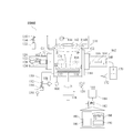
- FIG. 1 is a schematic cross-sectional view showing a configuration of a volume reduction processing system 1000 according to the first embodiment of the present invention.
- the volume reduction processing system 1000 includes a radioactivity meter 102, a volume reduction processing apparatus 110, and a processing stop point calculation unit 180.
- the radiometer 102 is an arbitrary radiometer configured to measure the radioactivity of the resin 20 to be processed before being supplied to the volume reduction treatment device 110.
- a typical radiometer 102 may include a semiconductor detector that measures gamma rays by energy decomposition.
- the radiometer 102 outputs radioactivity data or a radioactivity signal indicating the radioactivity value of the resin 20 to be treated.
- the radiometer 102 is a radiometer having ⁇ -ray energy resolution, for example, the radioactivity in the specified nuclide can be measured while the radionuclide is specified by the energy of the emitted ⁇ -ray. It becomes possible.
- the arrangement of the radiometer 102 is not limited to the position shown in FIG. 1, and is arranged at an arbitrary position where the radioactivity value of the resin 20 to be processed can be acquired.
- the volume reduction processing apparatus 110 includes a stage 112 on the vacuum container 114 on which the resin to be processed 20 (the resin 22 to be processed) is placed.
- the configuration and operation of the volume reduction processing device 110 will be described in detail later.
- the resin 20 to be treated is supplied to the stage 112 by the supply mechanism 122 through the supply side gate valve G1.
- the supply mechanism 122 is provided with a quantitative mass 124 having a predetermined volume.
- the fixed mass 124 is delivered by the arm 126 to the position above the stage 112 through the opened supply-side gate valve G1.
- the resin 20 to be treated in the quantitative mass 124 is dropped onto the upper surface of the stage 112.
- a fixed mass driving mechanism 128 that enables such an operation is connected to the arm 126.
- the stage 112 is a metal tray that is made in the shape of a circular dish and on which the resin to be treated 22 can be placed.
- a heater 116 is provided inside the flat plate portion of the stage 112 on which the resin 22 to be processed is placed, and the temperature of the stage 112 itself can be raised by the heater 116.
- the stage 112 is configured to be able to rotate around an axis that passes through the center of the circular dish and is perpendicular to the flat plate portion while maintaining the airtightness of the vacuum vessel 114.
- the drive mechanism 118 can cause the stage 112 to perform a slow rotation operation, for example, once per several minutes to several times per minute. Further, the stage 112 is manufactured so that the vertical position, that is, the height of the paper surface of FIG.
- the stage 112 can be changed by a driving mechanism (not shown).
- the stage 112 is connected to a heating power source 120 that supplies controlled power to the heater 116.
- the stage 112 is equipped with a temperature sensor (not shown) that measures the temperature of the stage 112 itself.
- the power supplied to the heater 116 is controlled according to the temperature measurement signal from the temperature sensor.
- the temperature of the stage 112 can be controlled to a temperature suitable for volume reduction processing such as 400 ° C. or 700 ° C., for example.
- the volume reduction processing apparatus 110 includes a vacuum container 114 that is generally formed in a cylindrical shape.
- a gas supply line 130 for supplying oxygen to the internal space of the vacuum container 114 is connected to the vacuum container 114. From the gas supply line 130, oxygen from the oxygen cylinder 132 is supplied to the internal space of the vacuum vessel 114 through the regulator valve 134 at a controlled flow rate.
- a high frequency coil 142 is disposed on the outer surface of the top wall 114R of the vacuum vessel 114 on the atmosphere side.
- the high frequency coil 142 is a coil formed by spirally forming a linear member such as copper.
- the high-frequency coil 142 has a connecting portion at a spiral center portion and a peripheral portion.
- the high-frequency coil 142 is used to excite plasma in the space inside the top wall 114 ⁇ / b> R of the vacuum vessel 114, that is, the space S above the stage 112. For this reason, a high frequency power supply 144 having a frequency suitable for inductively coupling with the plasma is connected to the high frequency coil 142.
- This plasma is mainly oxygen plasma because it is excited while supplying oxygen.
- the top wall 114 ⁇ / b> R of the vacuum vessel 114 is an insulator in order to generate a high-frequency electromagnetic field by the high-frequency coil 142 in the space S.
- the top wall 114R is made of fused silica glass.
- the configuration and arrangement of the high-frequency coil that can be employed in the present embodiment are not particularly limited to the arrangement of the high-frequency coil 142.
- the volume reduction process of this embodiment can be performed by using a high-frequency coil having an arbitrary shape and arrangement suitable for excitation of oxygen plasma.
- the exhaust line 150 for keeping the inside in a reduced pressure state is also connected to the vacuum vessel 114.
- An exhaust valve 152 and a vacuum pump 154 are connected to the exhaust line 150.
- the opening degree of the exhaust valve 152 is controlled by the pressure control unit 158, and the pressure control unit 158 continuously performs pressure control based on a signal from the pressure sensor 160 that measures the pressure in the internal space of the vacuum vessel 114. ing.
- the pressure control unit 158 automatically controls the pressure of the vacuum vessel 114 as an APC (Automatic Pressure Controller) that controls the exhaust valve 152 based on a signal from the pressure sensor 160.
- APC Automatic Pressure Controller
- a carbon dioxide sensor 156 is connected to the outlet side path of the vacuum pump 154.
- the carbon dioxide sensor 156 outputs concentration data or a concentration signal corresponding to the concentration of carbon dioxide gas measured in the exhaust path from the vacuum vessel 114.
- any type of gas sensor that achieves the purpose of measuring the concentration of the carbon-containing gas can be used in place of the carbon dioxide sensor 156.
- the same purpose can be achieved by using a carbon monoxide sensor instead of a carbon dioxide sensor.
- the gas sensor such as the carbon dioxide sensor 156 may be provided not on the outlet side path of the vacuum pump 154 but on, for example, a wall surface of the vacuum vessel 114 or a path to the vacuum pump 154 in the exhaust line 150. .
- the supplied resin 20 (processed resin 22) is subjected to volume reduction while being placed on the stage 112.
- This volume reduction process is performed by a heat process by the stage 112 and an oxidation process by the oxygen plasma P. That is, the volume reduction treatment apparatus 110 heats the resin 22 to be treated, and oxidizes at least one or both of the resin 22 itself and the gas released from the resin 22 with the oxygen plasma P. . Details of this processing will be described later.
- the solid content (residual solid matter) placed on the stage 112 is obtained from the resin 22 to be treated. For this reason, after the processing is finished, the solid residue is removed from the stage 112 by the discharge mechanism 162 and discharged to the outside of the vacuum vessel 114.
- a discharge-side gate valve G2 is attached to the vacuum vessel 114.
- a suction pipe 164 including a recovery nozzle 166 is disposed in the discharge mechanism 162. The suction pipe 164 is connected to a discharge drive mechanism 168 for driving the position of the recovery nozzle 166 to a position suitable for suction of residual solid matter on the stage 112 in a state where the discharge side gate valve G2 is open.
- the residual solid sucked by the suction pipe 164 is recovered while preventing scattering through a bag filter or a cyclone (both not shown) for recovering the residual solid from the airflow, and is temporarily stored in the residual solid container 170. It is stored in.
- the residual solid container 170 is provided with an additional radiometer 172 for measuring the radioactivity remaining in the final residual solid.
- the solid residue in the solid residue container 170 is then sealed with, for example, cement or resin to enhance safety, and is transported to a suitable facility such as a final disposal site, where it is stored or disposed semi-permanently.
- the additional radiometer 172 outputs the radioactivity actually indicated by the solid residue as residual radiation data or residual radiation signal.
- the residual radiation data or residual radiation signal output from the additional radiometer 172 can be used to determine the storage class of the residual solids.
- the processing stop point calculation unit 180 is a functional unit implemented as a program in the computer 182, for example.
- the function of the processing stop point calculation unit 180 is a function for determining a processing stop point for volume reduction processing of the resin 20 to be processed to the volume reduction target value by the volume reduction processing device 110.
- determining the processing stop point an operation based on the volume reduction target value and the radioactivity data or radioactivity signal obtained by the radiometer 102 is performed. Then, the determined process stop point is stored in the process stop point storage unit 188.
- the volume reduction processing device 110 is controlled by the computer 182 or the sequence control unit 184 in which the processing stop point calculation unit 180 is mounted.
- the volume reduction processing apparatus 110 stops at least one of the heating process and the oxidation process when the process stop point is reached.
- the computer 182 in which the processing stop point calculation unit 180 is mounted executes control based on the value of the processing stop point in the processing stop point storage unit 188, for example. Alternatively, the computer 182 transmits a control signal to the sequence control unit 184 to cause the sequence control unit 184 to perform similar control.
- the computer 182 in which the processing stop point calculation unit 180 is mounted receives data or signals from the volume reduction processing device 110, the radiometer 102, the carbon dioxide sensor 156, and the additional radiometer 172. Further, the computer 182 controls the operation of the volume reduction processing apparatus 110 directly or through the sequence control unit 184, for example.
- the elements of the volume reduction processing apparatus 110 that receive control from the computer 182 directly or through the sequence control unit 184 include a stage driving mechanism 118, a heating power source 120, a quantitative mass driving mechanism 128, a regulator valve 134, a high-frequency power source 144, A pressure control unit 158, a discharge drive mechanism 168, a supply side gate valve G1, and a discharge side gate valve G2 are included.
- the pressure control unit 158 itself operates so as to make the pressure inside the vacuum vessel 114 constant by controlling the pressure sensor 160 and the exhaust valve 152, and at the same time receives the control by the sequence control unit 184,
- the pressure command value which is the control target value, may be changed.
- the processing stop point calculation unit 180 further includes an integration unit 186 that calculates an integrated value obtained by integrating at least one of the concentration data from the carbon dioxide sensor 156 and the concentration value converted from the concentration signal.
- the accumulating unit 186 is a functional unit that is realized using the computing function of the computer 182.
- the accumulating unit 186 performs an operation of integrating the concentration data or the concentration signal according to the concentration of carbon dioxide gas from the carbon dioxide sensor 156 over time.
- the integrated value is an integrated value from the initial stage of the process to each time point indicating the total amount of carbon dioxide gas (carbon-containing gas) released from the resin 22 to be processed and measured by the carbon dioxide sensor 156.
- the processing stop point calculation unit 180 receives the integrated value output from the integrating unit 186 and uses it to determine how much carbon-containing gas has been released from the resin 22 to be processed up to that point.
- the integrated value of the carbon-containing gas such as the released carbon dioxide is used as an index indicating the degree of progress of the volume reduction treatment of the resin 20 to be treated, as will be described later.
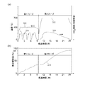
- FIG. 2 is a graph (FIG. 2 (a)) of an index (temperature and carbon dioxide concentration) indicating the state of the volume reduction processing system for the state of the volume reduction processing system 1000, and an estimation indicating the state of volume reduction of the resin. It is a graph (FIG.2 (b)) of a weight loss rate.
- the index shown in FIG. 2A as the index of the state of the volume reduction processing system 1000 is the temperature of the stage 112 (curve 202) and the value of the carbon dioxide concentration obtained from the carbon dioxide sensor 156 (curve 204).
- the estimated weight reduction rate curve 214) which estimated the mode of volume reduction of resin.
- the temperature of the stage 112 indicated by the curve 202 is a temperature indication value indicated by a temperature sensor (not shown) provided in the stage 112, and the value is clearly shown on the vertical axis as a guide.
- the curve 204 indicating the value of the carbon dioxide concentration output from the carbon dioxide sensor 156 shows only temporal behavior, and the scale of the value is an arbitrary unit.
- the value of the carbon dioxide concentration indicated by the curve 204 is plotted so as to be plotted linearly and the horizontal axis is zero.
- the entire process shown in FIG. 2A takes about 24 hours.
- the sub-batch is a processing unit obtained by further subdividing a batch of the resin 20 to be processed that becomes a unit processing amount in a series of volume reduction processing.
- one batch of the resin 20 to be processed is processed in the first to fourth sub-batches for a part of the processing, and the remaining one is processed as the original one batch.
- the description based on FIG. 2A describes a technique for performing a volume reduction process as high as possible for the purpose of helping understanding of the process by the volume reduction processing system 1000 of the present embodiment.
- the volume reduction rate is as high as possible. This corresponds to the case where volume reduction processing is executed so as to be obtained.
- the embodiment of the present invention includes a mode in which processing is stopped or stopped at an appropriate time using a processing stop point.
- the volume reduction processing by the volume reduction processing system 1000 is roughly divided into two processing phases, that is, a first phase (first processing) and a second phase (second processing). ing.
- first phase the stage 112 is heated to approximately 400 ° C.
- second phase the stage 112 is heated to approximately 700 ° C.
- these temperatures show finer temporal variations as shown by the curve 202.
- the treatment target of the volume reduction treatment system 1000 is an ion exchange resin used by a nuclear power generation facility or the like
- the resin 22 to be treated is an ion exchange resin and a radioactive substance accompanied by the ion exchange resin. And the remaining moisture.
- ion exchange resins used in nuclear power generation facilities are accompanied by radioactive substances including radioisotopes by being adsorbed or retained on the form of ions or corrosive organisms (cladding).
- first phase carbonization is performed by heating the resin 22 to be treated.
- This process is a process first performed on the resin 22 to be processed.
- the resin 22 to be treated When the resin 22 to be treated is placed on the stage 112 and heating is started, it releases a large amount of water vapor until it reaches a temperature of about 400 ° C., and decomposes by desorption / decomposition of lower molecules such as anion exchange groups. Release gas. Thereafter, when the temperature sufficiently rises to around 400 ° C., the resin 22 to be treated further releases decomposition gas due to the separation and decomposition of the higher-level components due to the decomposition of the resin base material.
- the release of these cracked gases is close to the phenomenon in which general organic substances release cracked gases by heat.
- the high-frequency coil 142 is supplied with electric power for exciting the plasma P by inductive coupling. Therefore, the released cracked gas is oxidized by the oxygen plasma P excited in the space above the stage 112.
- components that are susceptible to oxidation in the cracked gas such as carbon components, are oxidized.
- the gas generated by oxidizing the decomposition gas by the oxygen plasma P, that is, the processing gas contains carbon dioxide and carbon monoxide. This processing gas is exhausted through the exhaust line 150.
- the decomposition in this process is intense immediately after the start of the process and starts to weaken after a certain period of time. This corresponds to the consumption of components that are decomposed by the temperature.
- the stage 112 is left with the carbonization progress after the decomposition gas component is released from the resin 22 to be treated. Even if this carbonized resin 22 to be treated is sufficiently treated in the first phase, it only proceeds to the carbonized state. For this reason, the carbon component remains in the resin 22 to be treated at this time.
- the decomposition treatment of the resin 22 to be treated, the carbonization treatment, and the oxidation treatment of the decomposition gas are performed by combining the heating of the stage 112 and the oxidation by the oxygen plasma P.
- the carbon component of the cracked gas in the first phase is discharged from the exhaust line 150 as carbon dioxide or carbon monoxide gas in the oxidized processing gas, and its concentration is measured by the carbon dioxide sensor 156.
- the carbon dioxide concentration in the first phase increases with increasing temperature in each sub-batch, and after a high value is maintained for a certain time, it decreases with consumption of the components to be decomposed.
- the value of the carbon dioxide concentration is a direct index indicating the amount of carbon per unit time that is oxidized in the resin 22 to be treated.
- the value of the carbon dioxide concentration is an indirect indicator for all components oxidized in the resin 22 to be treated.
- all the components oxidized in the to-be-processed resin 22 may contain a nitrogen component, a sulfur component, and a hydrogen component other than a carbon component.
- the resin 22 to be processed is processed in units of sub-batches in which the resin 22 to be processed is subdivided into the processing capacity range of the volume reduction processing device 110.
- FIG. 2A shows a state in which the resin 22 to be treated is put into four sub-batches.
- the progress of carbonization and decomposition treatment by heating for the first sub-batch of the resin 22 to be treated is monitored through the value of the carbon dioxide concentration.
- the supply-side gate valve G1 is opened, and the next sub-batch, that is, the second sub-batch treated resin 22 is additionally charged.
- the second sub-batch processed resin 22 is supplied to the stage 112 in that state. Therefore, the resin 22 to be processed is processed in both the newly added second sub-batch and the first sub-batch being processed. Thereafter, the third sub-batch and the fourth sub-batch are similarly processed.
- the first phase of the resin 22 to be treated is advanced in this way because a large amount of cracked gas is generated from the resin 22 to be treated in the first phase compared to the second phase. This is because the ability to process may be insufficient.
- the second phase will be described.
- the vacuum vessel 114 remains decompressed without being released to the atmosphere.
- the pressure that is, the degree of vacuum is changed between the first phase and the second phase.
- the processing target of the second phase is a semi-processed product carbonized through the first phase processing as the first to fourth sub-batch of the resin 22 to be processed remaining on the stage 112.
- this half-processed product is also referred to as a resin 22 to be processed.
- the temperature of the stage 112 is raised to 700 ° C. in that state.
- the second phase is a further volume reduction treatment in which the carbon component of the carbonized resin 22 to be treated is reduced by ashing that combines heat treatment and oxygen plasma.
- oxygen plasma P is used as in the first phase.
- the high-frequency coil 142 is supplied with electric power for exciting the plasma P by inductive coupling.
- oxidizing the cracked gas was an action expected of the oxygen plasma P
- the oxygen plasma was expected in the action of ashing the carbonized resin 22 to be treated. P is excited.
- the conditions for exciting the oxygen plasma P are different between the first phase and the second phase.
- a higher pressure than the first phase is selected for the excitation condition of the second phase oxygen plasma.
- the oxygen supply direction is also selected so that the airflow from the top wall 114R toward the stage 112 in the second phase is larger than that in the first phase.
- the carbon components remaining in the resin 22 to be treated are discharged from the exhaust line 150 as a treatment gas such as carbon dioxide or carbon monoxide gas. Is done.
- the carbon dioxide concentration in the second phase also increases as the temperature increases, and after a high value is maintained for a certain time, it decreases according to the consumption of the component to be oxidized.
- the value of the carbon dioxide concentration obtained from the carbon dioxide sensor 156 is a direct index indicating the amount of carbon per unit time oxidized in the resin 22 to be treated, It is also an indirect indicator for all components oxidized in the resin 22 to be treated.
- the process of the second phase is continued until the carbon dioxide concentration obtained from the carbon dioxide sensor 156 becomes zero. That is, the graph of FIG. 2A shows the process of processing until the component to be removed by oxidation is eliminated from the resin 22 to be treated under the second phase conditions. At the time of the right end of the graph of FIG. 2A, the substance finally remaining in the treated resin 22 is a metal oxide containing a radionuclide and a slight amount of carbon that cannot be removed under the conditions of the second phase. It is an ingredient. For this reason, when the processing of the second phase is completed, the residual solid matter that has been subjected to the volume reduction process to such an extent that the volume cannot be further reduced is left on the stage 112.
- the graph in FIG. 2B shows how the volume of the resin 22 to be treated is reduced with the progress of such treatment by the estimated weight reduction rate.
- a curve 214 shown in this graph is an estimated value estimated from the integrated value of the carbon dioxide concentration at each stage showing the state of volume reduction.
- the degree of volume reduction is estimated not by the volume but by the degree of mass (weight) reduction, that is, the weight loss rate.
- this estimated weight loss rate it is calculated as follows. In advance, the total mass of the batch (first to fourth sub-batch) that is a processing unit of the resin 20 to be processed is measured. Since the mass is a mass including water, the dry mass is determined by subtracting the mass of water from the mass of the resin 20 to be treated using the moisture content measured separately.
- the volume-reduced treatment is the mass due to the oxidized component such as nitrogen component, sulfur component, and hydrogen component, if present, in addition to the mass of the carbon component. is there. Therefore, the weight loss rate at each time point is (1-Mass of residual solid at each time point / Dry weight) ⁇ 100% Formula (1) Can be obtained as Here, for the sake of simplicity, the weight loss rate is described only with the definition using the dry mass. It is also possible to define the weight loss rate by another definition, such as using a mass including moisture instead of using a dry mass.
- the internal processing of the vacuum vessel 114 is performed. Therefore, it is possible to actually measure the mass of the residual solid according to the formula (1) after the processing of the second phase is completed. That is, the weight reduction rate is obtained only after the second phase is completed and the mass of the residual solid matter sucked by the discharge mechanism 162 and temporarily stored in the residual solid matter container 170 is used. For this reason, it is practically difficult to obtain the weight loss rate at each time point in Equation (1).
- the estimated weight loss rate at each time point is k x integrated value of carbon-containing gas concentration / dry mass x 100% (2) It can be expressed as However, when the carbon dioxide sensor 156 of FIG. 1 is used, the integrated value of the carbon-containing gas concentration is an integrated value obtained by integrating the measured carbon dioxide value indicated by the carbon dioxide sensor 156 with time, and k is proportional. It is a coefficient. In order to determine this k, as shown in FIGS.
- FIG. 2 (b) the weight loss obtained from the mass of the residual solid material that has been processed and carried out until the concentration of the carbon-containing gas becomes zero is shown as the reaching point RF.
- a curve 214 in FIG. 2B is a plot in which the final value of the integrated value of the carbon-containing gas concentration is matched with the arrival point RF.
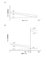
- FIG. 3 is an explanatory diagram showing how the processing cost and the storage cost change with respect to the weight loss rate.
- FIG. 3A shows a case where the storage class does not change with respect to the weight loss rate
- FIG. 3B shows a case where the storage class changes with respect to the weight loss rate.
- a straight line 302 in FIG. 3A indicates the processing cost of the volume reduction processing, and is shown as a straight line that increases as the weight reduction rate increases.
- a straight line 304 indicates the storage cost required for storing the residual solid matter. The storage cost of the residual solids decreases as the weight reduction rate increases as long as the storage class does not change. Therefore, when the storage class does not change, the total cost decreases as the weight reduction rate increases, as indicated by the straight line 306 that is the sum of the straight line 302 and the straight line 304.
- the volume reduction process is preferably stopped or stopped before the weight reduction value at which the total cost jumps discontinuously. That is, the volume reduction target value is set to a value that is smaller by a certain margin ⁇ from the value of the weight reduction rate RJ that causes a discontinuous jump in the total cost. This is the volume reduction target value RT in FIG.
- the actual storage class category is determined by the radioactivity concentration. For this reason, even if there are residual solids obtained by volume reduction treatment at the same weight reduction rate, if the initial radioactive concentration value of the resin 22 to be treated is different, it can be classified into different storage classes There is sex. That is, in order to determine the weight loss rate RJ at which a discontinuous jump occurs in the total cost in FIG. 3B, the radioactivity concentration that becomes the boundary value for storage classification and the radioactivity measured by the radiometer 102 are measured. It is necessary to calculate the value of the weight loss rate at which a discontinuous jump occurs in the total cost from both the initial radioactive concentration of the treated resin 22. If the calculated value is used, it is possible to determine the weight reduction target value RT as a weight reduction rate that is smaller by the margin ⁇ after determining the weight reduction rate RJ that causes a discontinuous jump in cost. .
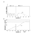
- FIG. 4 is a graph showing the progress of processing when the volume reduction target value RT is given.
- FIG. 4 (a) is a graph showing the change over time in the carbon dioxide concentration in the volume reduction process, similar to that shown in FIG. 2 (a).
- the integrated value of the concentration of carbon dioxide gas is a value obtained by integrating the concentration of carbon dioxide gas from the start of processing to each time point. The value is converted into the estimated volume reduction rate according to the above-described equation (2). The converted volume reduction rate is shown in FIG. FIG.
- FIG. 4B is a graph showing the change over time of the estimated weight loss rate in the volume reduction process, similar to that shown in FIG.
- the volume reduction target value RT is shown in FIG. 4B as a value on the vertical axis.
- the processing stop point calculation unit 180 determines the processing stop point if the calculation of Expression (2) is performed at each time point using the integrated value obtained by the integrating unit 186 and the progress of the process is monitored. Can do.
- the process of the determination is performed by several modes depending on the type of measurement value or physical quantity that determines the process stop point.
- the processing stop point is typically determined as a weight loss rate of the resin to be processed, an integrated value of a carbon-containing gas such as carbon dioxide or carbon monoxide, a processing required time, or a processing stop time.
- the processing stop point when specified by the weight loss rate of the resin to be processed is set as the weight reduction rate processing stop point RSP.
- the weight reduction rate processing stop point RSP the volume reduction target value RT (FIG. 3B) itself is most typically selected as shown in FIG.
- the processing stop point storage unit 188 stores the value of the weight reduction rate processing stop point RSP as it is.
- a value smaller than the volume reduction target value RT by a certain margin may be used as the weight reduction rate processing stop point RSP.
- the processing stop point may be determined by the integrated value of the carbon-containing gas.
- the processing stop point is defined as a carbon processing stop point CSP (not shown).
- This carbon treatment stop point CSP is most typically the integrated value of the carbon-containing gas that gives the volume reduction target value RT (FIG. 3B). Therefore, the carbon treatment stop point CSP is easily calculated as an integrated value of the carbon-containing gas when Equation (2) is equal to the volume reduction target value RT.
- the processing stop point storage unit 188 stores the carbon processing stop point CSP. In Modification 1 described later, a method for determining the carbon processing stop point CSP with higher accuracy is described.
- the processing stop point may be determined as a processing required time or a processing stop time.
- the processing stop point is set as a time processing stop point TSP.
- This time processing stop point TSP is most typically a processing time for giving a volume reduction target value RT (FIG. 3B), as shown in FIG. 4B.
- the curve 214 (FIG. 2B) needs to be obtained in advance. For this purpose, processing is performed in advance using a resin sample of the same type as the resin 20 to be processed, and the reaching point RF is determined to obtain the curve 214 in FIG. 2B, and the curve 214 is processed.
- the processing stop point storage unit 188 stores the time processing stop point TSP.
- the processing stop point can be determined by several modes. In addition, regardless of which process stop point is employed, it is possible to set the arbitrary margin and determine the process stop point. Any processing stop point is determined based on the volume reduction target value RT and the radioactivity data or radioactivity signal.
- the process stop point determined by the process stop point calculation unit 180 is preferably the second phase (second process). ) Is set to be located in the processing period. Although a large amount of carbon still remains in the first phase (first treatment) in which the carbonization treatment is performed, sufficient treatment is proceeding in the second phase, and the subsequent disposal, that is, semi-permanent This is because it is difficult for storage to occur.
- FIG. 4A is a value of the carbon dioxide concentration obtained from the carbon dioxide sensor 156
- a curve 414 of FIG. 4B is an estimated weight loss rate estimated from the state of volume reduction of the resin.
- FIG. 4A when the process is stopped when the process stop point is reached, the concentration of carbon dioxide rapidly decreases from that point, and the estimated weight loss rate does not increase. That is, the process is stopped soon.
- FIG. 4A the curve when the processing stop point is not used (FIG. 2A) is clearly indicated by a chain line.
- the process is stopped typically by stopping the heating process by the heater 116 and stopping the oxidation process by the oxygen plasma P.
- the oxidation treatment is stopped by stopping the supply of oxygen from the gas supply line 130 and stopping the supply of power from the high frequency power supply 144.
- an arbitrary stop process that stops the progress of the volume reduction process can be executed.
- the generation of decomposition gas is small, and the ashing of the resin 22 to be treated is the main treatment. Therefore, whether the heat treatment by the heater 116 is stopped or the oxidation by the oxygen plasma P is stopped.
- the volume reduction process can be terminated simply by executing either one.
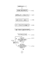
- a process of measuring initial radioactivity S102
- a radiometer 102 is used.
- a processing stop point is determined (S104).
- the operation of the processing stop point calculation unit 180 described above is performed. That is, for example, when the weight reduction rate processing stop point RSP is used as the processing stop point, the value of the volume reduction target value RT is stored in the processing stop point storage unit 188 as it is.
- the carbon processing stop point CSP is adopted as the processing stop point, typically, the integrated value of the carbon-containing gas when the equation (2) is equal to the volume reduction target value RT is calculated, and the value is It is stored in the processing stop point storage unit 188 as a carbon processing stop point CSP.
- the volume reduction target value RT is typically set from the curve 214 (FIG. 2B) for the same type of resin measured in advance.
- the given time processing stop point TSP is obtained and stored in the processing stop point storage unit 188.
- the carbon treatment stop point CSP is adopted as a typical example.
- the supply-side gate valve G1 is opened and the sub-batch (first sub-batch) to be treated 22 is supplied, the supply-side gate valve G1 is closed again.
- This is a process of supplying a constant volume of the resin 22 to be processed by the fixed mass 124 and is a process of placing the resin 22 to be processed on the stage 112 of the vacuum vessel 114 in advance as a first sub-batch.
- the inside of the vacuum container 114 is depressurized (S106). For example, when the pressure reaches about 10 Torr (1.33 kPa), the stage 112 is heated to 400 ° C. by the heater 116 as the first phase process (S108).
- the vacuum pump 154 continues a certain exhaust operation, the pressure is input to the pressure control unit 158 by the pressure sensor 160 and automatically controlled through the opening degree of the exhaust valve 152.
- the sub-batch treated resin 20 that is, for example, when the sub-batch is prepared from the first to the fourth sub-batch and the treated resin 20 being processed is that of the fourth sub-batch (S116, N Branch), do not add. If the processing is continued as it is, the processing of the first phase is completed.
- the stage 112 is in a state in which the carbonized resin 22 is disposed.
- a process of ashing this is performed.
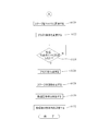
- the stage temperature is first raised to 700 ° C. (FIG. 6, S120).
- the plasma conditions are changed from those in the first phase according to the processing conditions in the second phase (S122).
- This change in the plasma conditions includes a change in various conditions such as a power setting change by the high-frequency power supply 144, a change in the flow rate and supply direction of oxygen gas, and a pressure change in the vacuum vessel 114 by the pressure control unit 158. Yes.
- the integrated value of the carbon-containing gas concentration increases.
- the computer 182 monitors whether the process stop point has been reached (S124).
- the process stop point stored in the process stop point storage unit 188 is used.
- the carbon processing stop point CSP is adopted, it is monitored whether or not the integrated value of the carbon-containing gas has reached the processing stop point.
- the processing stop point has not been reached (S124, branch of N), monitoring of the value is continued.
- the computer 182 or the sequence control unit 184 instructs to stop the exhaust operation of the vacuum vessel 114, stop the heating power source 120, and drive the discharge mechanism 162.
- the radioactivity of the residual solid after treatment is measured by an additional radiometer 172.
- the coefficient k is modified to be replaced in order to improve the processing accuracy. That is, the coefficient k is a function with respect to the integrated value of carbon dioxide.
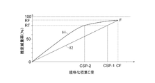
- FIG. 7 is an explanatory diagram illustrating the relationship between the estimated weight loss rate and the integrated concentration value of carbon dioxide gas before and after this deformation.
- the weight loss rate when processing until carbon dioxide gas is not released is a value where the value obtained by dividing the integrated value of carbon dioxide gas by the dry mass does not increase any more. It is assumed that the weight loss rate corresponding to CF corresponds to the arrival point RF on the vertical axis.
- the horizontal axis is normalized by using the dry mass of the resin 20 to be treated before being supplied, and adopts a “standardized accumulated C amount” which is (carbon dioxide gas concentration integrated value / dry mass).
- a “standardized accumulated C amount” which is (carbon dioxide gas concentration integrated value / dry mass).
- the range from the origin to the point CF shown in FIG. 7 actually covers the first phase process and the second phase process in which the processing conditions such as the heating temperature are greatly different from each other.
- the original change in weight loss rate is due to the fact that various components such as carbon, nitrogen, sulfur, and hydrogen are more likely to be released in the first phase or the second phase. It reflects the situation according to. Therefore, in general, although it passes through the origin and the point A, it can be said that it is a curve. Assuming a curve in this way corresponds to the coefficient k in the equation (2) being not a constant but a function of the concentration integrated value of the carbon-containing gas.
- the resin 22 to be treated is, for example, an ion exchange resin
- the nitrogen component, sulfur component, and hydroxyl group contained in the functional group of the ion exchange resin are carbon components.
- the first phase is carbonization.
- One typical example of the relationship between the actual weight loss rate value and the normalized integrated C amount value in such a case is an upwardly convex curve like a curve 84. In actuality, such a curve depends on the type of resin to be treated, that is, the resin classification, and does not always have a convex curve.
- the processing stop point that is, the carbon processing stop point CSP is determined with higher accuracy as the value of the standardized integrated C amount. It becomes.
- FIG. 7 clearly shows the carbon treatment stop point CSP-1 when the straight line 82 is used and the carbon treatment stop point CSP-2 when the curve 84 is used as the carbon treatment stop point CSP. The difference between the carbon processing stop points CSP-1 and CSP-2 becomes a problem in the implementation because the margin ⁇ (FIG.
- the volume reduction target value RT becomes the total cost.
- the inventor predicts that it is close to the weight loss rate RJ in which discontinuous jumps occur. If the carbon processing stop point CSP-2 determined with higher accuracy than the carbon processing stop point CSP-1 is adopted, the margin ⁇ can be selected to be a small value, so that the volume reduction target value RT jumps discontinuously to the total cost. It is possible to set a value closer to the weight loss rate RJ at which this occurs. For this reason, it is possible to set the volume reduction target value RT to a cost-effective value by determining the processing stop point with high accuracy.
- the curve 84 is preferably stored in the calibration curve data storage unit 190 (FIG. 1) as a calibration curve for each resin classification.
- Ion exchange resins are classified into various types depending on, for example, the ratio of anions and cations contained in the resin to be treated to the ion exchange resin, their types, and the processing system in which the ion exchange resin is used.
- the calibration curve data storage unit 190 stores, as a calibration curve, a curve 84 that matches at least a classification category for each resin that can use the same curve 84.
- the processing stop point calculation unit 180 determines the calibration curve data of the classification classification of the resin to which the next processed resin belongs from the calibration curve data storage unit 190. Is called from the calibration curve data storage unit 190. By doing so, it becomes possible to determine the processing stop point with higher accuracy reflecting the characteristics of the volume reduction processing that the resin of the resin 22 to be processed actually shows.
- the processing stop point calculation unit 180 accepts bulk density data and moisture content data. This data reception may be performed by communication from some device, or may be input by an operator of the volume reduction processing system 1000.
- the processing stop point calculation unit 180 can easily determine the dry mass for the next resin to be processed of the predetermined volume supplied by the supply mechanism 122 by reflecting the bulk density and moisture content. The ratio between the value and the dry mass can be reflected in the determination of the processing stop point.
- the present invention contributes to low-cost operation of nuclear power generation facilities using ion-exchange resin through enabling volume reduction with reduced total cost when considering storage costs.
Landscapes
- Engineering & Computer Science (AREA)
- Physics & Mathematics (AREA)
- General Engineering & Computer Science (AREA)
- High Energy & Nuclear Physics (AREA)
- Health & Medical Sciences (AREA)
- Environmental & Geological Engineering (AREA)
- Epidemiology (AREA)
- Life Sciences & Earth Sciences (AREA)
- Animal Behavior & Ethology (AREA)
- General Health & Medical Sciences (AREA)
- Public Health (AREA)
- Veterinary Medicine (AREA)
- Separation, Recovery Or Treatment Of Waste Materials Containing Plastics (AREA)
- Processing Of Solid Wastes (AREA)
Abstract
Description
[1 システム構成]
図1は、本発明の第1実施形態における減容処理システム1000の構成を示す概略断面図である。減容処理システム1000には、放射能計102と、減容処理装置110と、処理停止ポイント演算部180とが備えられている。
次に、減容処理システム1000による処理について、さらに図面を参照して説明する。図2は、減容処理システム1000の状態のための減容処理システムの状態を示す指標(温度と二酸化炭素濃度)のグラフ(図2(a))と、樹脂の減容の様子を示す推定減重率のグラフ(図2(b))である。減容処理システム1000の状態の指標として図2(a)に示した指標は、ステージ112の温度(曲線202)と、二酸化炭素センサー156から得られる二酸化炭素濃度の値(曲線204)である。また、図2(b)に示したものは、樹脂の減容の様子を推定した推定減重率(曲線214)である。
(1-各時点の残渣固形物の質量/乾燥質量)×100% 式(1)
として求めることが可能となる。なお、ここでは説明を簡明にするために、乾燥質量を用いた定義のみをもって減重率を説明している。乾燥質量を用いる代わりに水分を含む質量を用いて定義するなど、別の定義によって減重率を定めることも可能である。
k×炭素含有ガス濃度の積算値/乾燥質量×100% 式(2)
と表現することができる。ただし、炭素含有ガス濃度の積算値は、図1の二酸化炭素センサー156を用いる場合には、二酸化炭素センサー156の示した測定した二酸化炭素の値を時間とともに積算した積算値であり、kは比例係数である。このkを決定するためには、図2(a)および(b)に示したように、炭素含有ガスが生じなくなるまで減容処理を実行し、その最終の時点での式(1)の値と式(2)の値が等しくなるように決定すればよい。図2(b)には、炭素含有ガスの濃度が0になるまで処理を進めて搬出した残滓固形物の質量から求めた減重率を到達点RFとして示している。図2(b)の曲線214は、炭素含有ガス濃度の積算値の最終的な値を到達点RFに一致させてプロットしたものである。
ここまで可能な限り高い減容処理を行う手法について説明した。ところが実際の処理を行う場合には、保管クラスの区分を考慮に入れ適切なタイミングで処理を中止または停止するような動作が効率的である。
図3は、減重率に対して処理コストと保管コストが推移する様子を示す説明図である。このうち図3(a)は、減重率に対して保管クラスが変わらない場合を示し、図3(b)は、減重率に対して保管クラスが変わる場合を示している。図3(a)における直線302は、減容処理の処理コストを示しており、減重率を高めるのに応じて増加する直線として示されている。一方、直線304は、残渣固形物の保管に要する保管コストを示している。残渣固形物の保管コストは、保管のクラスが変わらない範囲では減重率が高くなるほど低下する。したがって、保管のクラスが変わらない場合には、直線302と直線304の和である直線306によって示されるように、総コストは減重率が高まるほど低下する。
ここで、減容処理を行って例えば炭素成分が減少して樹脂の減容が進むと、単位体積あたりの放射能の値、すなわち放射能濃度(activity concentration)が高まって、保管クラスが次の高い濃度の保管クラスになってしまうような場合がある。実際の処理のコストをみると、その高い濃度の保管クラスの廃棄物に課される規則に則った保管のためのコストは、低い濃度の保管クラスのそれと比較して、例えば10倍などに跳ね上がる。これを分断された直線によって示すのが、図3(b)に示す直線314Aおよび314Bである。このような保管コストのジャンプが生じる場合、直線302の減容処理の処理コストとの和もやはり分断された直線316Aおよび316Bのようになり、減重率に対する総コストにもジャンプが生じてしまう。この場合、減容処理は、総コストが不連続的にジャンプする減重率の値の前に中止または停止することが好ましい。すなわち、減容目標値としては、総コストに不連続なジャンプが生じる減重率RJの値から、ある余裕Δだけ小さい値に設定する。これが図3(b)の減容目標値RTである。
実際の保管クラスの区分は、放射能濃度によって決定される。このため、同じ減重率で減容処理されて得られた残渣固形物があったとしても、被処理樹脂22の初期の放射能濃度の値が異なれば、別々の保管クラスに分類される可能性がある。つまり、図3(b)の総コストに不連続なジャンプが生じる減重率RJを決定するためには、保管クラス分けの境界値となる放射能濃度と、放射能計102によって測定される被処理樹脂22の初期の放射能濃度との両方から、総コストに不連続なジャンプが生じる減重率の値を算定する必要がある。その算定された値を用いれば、コストに不連続なジャンプが生じる減重率RJを決定した後、上記余裕Δの分だけ小さい減重率として減容目標値RTを決定することが可能となる。
次に、本実施形態の処理動作を、フローチャートを参照して具体的に説明する。図5および図6は、本実施形態の減容処理システム1000によって実施される減容処理動作を説明するフローチャートである。必要に応じてこれまで参照した図面も参照する。
次に、本実施形態の処理停止ポイントの決定の精度を高めるための変形例について説明する。上述の式(2)では、比例係数kを用いる比例関係によって炭素含有ガス濃度の積算値を減容率に対応させていた。ここで比例関係を用いることは、暗黙にいくつかの仮定を含んでいたものといえる。まず、比例関係を用いることは、排気バルブ152および真空ポンプ154を通じた排気ライン150の排気速度が一定であると仮定していることとなる。本来は被処理樹脂22の減容処理の経過中に二酸化炭素センサー156によって測定される炭素含有ガス濃度を単純に積算せず、炭素含有ガスの濃度に排気速度を乗じた単位時間あたりの炭素含有ガス濃度の発生量を算出する必要がある。この補正のためには、排気速度を推定したり流量計を用いたりする。供給される酸素ガスの流量の値を排気速度と関連づけることも可能である。
最後に、高い精度で処理停止ポイントを決定するための別の変形例を変形例2として説明する。図1に示したように、被処理樹脂20は定量マス124によって供給される。このため、被処理樹脂20は、質量(重量)ではなく、容積によって一定量ずつ供給されている。ここで、ガス中の炭素の放出量を反映させた推定減重率(式(2)、図7)は、炭素含有ガス濃度の積算値と乾燥質量との比率として決定される。したがって、未処理の被処理樹脂20のかさ密度(powder density)が与えられれば、処理停止ポイント演算部180は式(2)の値や図7の横軸の値を決定することが容易になる。特に乾燥質量を決定するためには、今次の被処理樹脂20の水分率も利用することが好ましい。このため処理停止ポイント演算部180は、かさ密度データと水分率データとを受け付ける。このデータの受付は、何らかの装置からの通信によって行なわれてもよいし、また、減容処理システム1000のオペレータによる入力を受け付けるものであってもよい。処理停止ポイント演算部180は、かさ密度と水分率とを反映させることにより、供給機構122によって供給される所定容積の今次の被処理樹脂に対する乾燥質量を決定することが容易に行えるため、積算値と乾燥質量との比率を処理停止ポイントの決定に反映させることが可能となる。
20 被処理樹脂
22 供給された被処理樹脂
102 放射能計
110 減容処理装置
112 ステージ
114 真空容器
114R 頂部壁
116 ヒーター
118 ステージ駆動機構
120 加熱用電源
122 供給機構
124 定量マス
126 アーム
128 定量マス駆動機構
130 ガス供給ライン
132 酸素ボンベ
134 レギュレータバルブ
142 高周波コイル
144 高周波電源
150 排気ライン
152 排気バルブ
154 真空ポンプ
156 二酸化炭素センサー
158 圧力制御部
160 圧力センサー
162 排出機構
166 回収ノズル
164 吸引パイプ
170 残渣固形物容器
172 追加の放射能計
180 処理停止ポイント演算部
182 コンピューター
184 シーケンス制御部
188 処理停止ポイント格納部
190 検量線データ格納部
202、204、214、404、414、84 曲線
302、304、82 直線
314、316 分断された直線
CSP 炭素処理停止ポイント
G1 供給側ゲートバルブ
G2 排出側ゲートバルブ
P プラズマ
RJ ジャンプが生じる減重率
RT 減容目標値
RF 到達点
RSP 減重率処理停止ポイント
TSP 時間処理停止ポイント
Δ 余裕
Claims (16)
- 放射性物質を伴う被処理樹脂の放射能を測定するようになっており、該放射能の値を示す放射能データまたは放射能信号を出力する放射能計と、
前記被処理樹脂を加熱処理し、該被処理樹脂それ自体と該被処理樹脂から放出されるガスとの少なくともいずれかまたは両方を酸素プラズマによって酸化処理することにより、前記被処理樹脂を減容処理する減容処理装置と、
該減容処理装置によって前記被処理樹脂を減容目標値まで減容処理するための処理停止ポイントを、該減容目標値と前記放射能データまたは前記放射能信号とに基づいて決定する処理停止ポイント演算部と
を備え、
前記減容処理装置が、前記処理停止ポイントに達すると前記加熱処理および前記酸化処理のうちの少なくともいずれかの処理を停止する
減容処理システム。 - 前記減容処理装置の真空容器と該真空容器からの排気経路とのうちの少なくともいずれかの炭素含有ガスの濃度を測定して濃度データまたは濃度信号を出力するガス濃度測定器
をさらに備え、
前記処理停止ポイント演算部が、前記濃度データまたは前記濃度信号の示す濃度の積算値を算出する積算部をさらに有するとともに、前記処理停止ポイントを決定する前記演算のために前記積算値を用いるものである
請求項1に記載の減容処理システム。 - 前記ガス濃度測定器から出力される処理の完了までの前記炭素含有ガスの濃度に関する検量線データを樹脂の分類区分ごとに格納する検量線データ格納部
をさらに備え、
前記処理停止ポイント演算部が、今次の被処理樹脂のための前記処理停止ポイントを決定するために、前記今次の被処理樹脂が属する樹脂の分類区分の検量線データを該検量線データ格納部から呼び出すものである
請求項2に記載の減容処理システム。 - 所定の容積を単位として前記被処理樹脂を供給する供給機構を前記減容処理装置が有し、
前記処理停止ポイント演算部が、
今次の被処理樹脂についてのかさ密度を示すかさ密度データと、該今次の被処理樹脂の水分率を示す水分率データとを受け付けて、
前記かさ密度と前記水分率とを反映させることにより、前記供給機構によって供給される前記所定容積の今次の被処理樹脂に対する乾燥質量を決定し、
前記積算値と前記乾燥質量との比率を、前記処理停止ポイントの決定に反映させる
ものである
請求項2に記載の減容処理システム。 - 前記減容処理装置が、
前記被処理樹脂を第1温度に加熱して分解または炭化によって該被処理樹脂から放出されたガスを前記酸素プラズマによって酸化する第1処理と、
該第1処理を経た前記被処理樹脂を前記第1温度よりも高い温度である第2温度に加熱して前記被処理樹脂それ自体を前記酸素プラズマによって分解または酸化することによって前記被処理樹脂を灰化する第2処理と
を実施するものである
請求項1に記載の減容処理システム。 - 前記処理停止ポイント演算部が、前記第2処理を処理している期間に位置するように前記処理停止ポイントを設定する
請求項5に記載の減容処理システム。 - 前記減容処理装置により前記処理停止ポイントまで処理が施された前記被処理樹脂の残渣固形物の放射能を測定して残留放射線データまたは残留放射線信号を出力する追加の放射能計
をさらに備える
請求項1に記載の減容処理システム。 - 前記減容目標値が、前記被処理樹脂の残渣固形物を廃棄または保管するための保管クラスに従って決定されている
請求項1に記載の減容処理システム。 - 放射能計が、放射性物質を伴う被処理樹脂の放射能を測定して、該放射能の値を示す放射能データまたは放射能信号を出力するステップと、
減容処理装置が、前記被処理樹脂を加熱処理し、該被処理樹脂それ自体と該被処理樹脂から放出されるガスとの少なくともいずれかまたは両方を酸素プラズマによって酸化処理することにより、前記被処理樹脂を減容処理するステップと、
処理停止ポイント演算部が、前記減容処理装置によって前記被処理樹脂を減容目標値まで減容処理するための処理停止ポイントとする処理所要時間または処理停止時刻を、該減容目標値と前記放射能データまたは前記放射能信号とに基づいて決定するステップと、
前記減容処理装置が、前記処理停止ポイントに達すると前記加熱処理および前記酸化処理のうちの少なくともいずれかの処理を停止するステップと
を含む
減容処理方法。 - ガス濃度測定器が、前記減容処理装置の真空容器と該真空容器からの排気経路とのうちの少なくともいずれかの炭素含有ガスの濃度を測定して濃度データまたは濃度信号として出力するステップと、
前記処理停止ポイント演算部が、積算部により、前記濃度データまたは前記濃度信号の示す濃度の積算値を算出するステップと、
前記処理停止ポイント演算部が、前記積算値を、前記処理停止ポイントを決定する前記演算のために用いるステップと
をさらに含む
請求項9に記載の減容処理方法。 - 検量線データ格納部が、前記ガス濃度測定器から出力される処理の完了までの前記炭素含有ガスの濃度に関する検量線データを樹脂の分類区分ごとに格納するステップと、
前記処理停止ポイント演算部が、今次の被処理樹脂のための前記処理停止ポイントを決定するために、前記今次の被処理樹脂が属する樹脂の分類区分の検量線データを該検量線データ格納部から呼び出すステップと
をさらに含む
請求項10に記載の減容処理方法。 - 前記減容処理装置の供給機構が、所定の容積を単位として前記被処理樹脂を供給するステップと、
前記処理停止ポイント演算部が、今次の被処理樹脂についてのかさ密度を示すかさ密度データと、該今次の被処理樹脂の水分率を示す水分率データとを受け付けるステップと、
前記処理停止ポイント演算部が、前記かさ密度と前記水分率とを反映させることにより、前記供給機構によって供給される前記所定容積の今次の被処理樹脂に対する乾燥質量を決定するステップと、
前記処理停止ポイント演算部が、前記積算値と前記乾燥質量との比率を、前記処理停止ポイントの決定に反映させるステップと
をさらに含む
請求項10に記載の減容処理方法。 - 前記減容処理するステップは、
前記減容処理装置が、前記被処理樹脂を第1温度に加熱して分解または炭化によって該被処理樹脂から放出されたガスを前記酸素プラズマによって酸化する第1処理ステップと、
前記減容処理装置が、該第1処理を経た前記被処理樹脂を前記第1温度よりも高い温度である第2温度に加熱して前記被処理樹脂それ自体を前記酸素プラズマによって分解または酸化することによって前記被処理樹脂を灰化する第2処理ステップと
を含むものである
請求項9に記載の減容処理方法。 - 前記処理停止ポイント演算部が、前記第2処理を処理している期間に位置するように前記処理停止ポイントを設定するステップ
をさらに含む
請求項13に記載の減容処理方法。 - 追加の放射能計が、前記減容処理装置により前記処理停止ポイントまで処理が施された前記被処理樹脂の残渣固形物の放射能を測定して残留放射線データまたは残留放射線信号として出力するステップ
をさらに含む
請求項9に記載の減容処理方法。 - 前記減容目標値が、前記被処理樹脂の残渣固形物を廃棄または保管するための放射能の区分に従って決定されている
請求項9に記載の減容処理方法。
Priority Applications (2)
| Application Number | Priority Date | Filing Date | Title |
|---|---|---|---|
| US13/640,419 US9040767B2 (en) | 2011-02-15 | 2012-02-06 | Resin volume reduction processing system and resin volume reduction processing method |
| JP2012544971A JP5168437B2 (ja) | 2011-02-15 | 2012-02-06 | 樹脂減容処理システムおよび樹脂減容処理方法 |
Applications Claiming Priority (2)
| Application Number | Priority Date | Filing Date | Title |
|---|---|---|---|
| JP2011029829 | 2011-02-15 | ||
| JP2011-029829 | 2011-02-15 |
Publications (1)
| Publication Number | Publication Date |
|---|---|
| WO2012111463A1 true WO2012111463A1 (ja) | 2012-08-23 |
Family
ID=46672391
Family Applications (1)
| Application Number | Title | Priority Date | Filing Date |
|---|---|---|---|
| PCT/JP2012/052586 Ceased WO2012111463A1 (ja) | 2011-02-15 | 2012-02-06 | 樹脂減容処理システムおよび樹脂減容処理方法 |
Country Status (3)
| Country | Link |
|---|---|
| US (1) | US9040767B2 (ja) |
| JP (1) | JP5168437B2 (ja) |
| WO (1) | WO2012111463A1 (ja) |
Cited By (3)
| Publication number | Priority date | Publication date | Assignee | Title |
|---|---|---|---|---|
| JP5872093B1 (ja) * | 2015-06-23 | 2016-03-01 | 株式会社神鋼環境ソリューション | 放射性物質除去方法及び放射性物質除去システム |
| JP5937258B1 (ja) * | 2015-06-23 | 2016-06-22 | 株式会社神鋼環境ソリューション | 放射性物質除去方法 |
| TWI562166B (ja) * | 2013-05-24 | 2016-12-11 | Inst Nuclear Energy Res |
Citations (2)
| Publication number | Priority date | Publication date | Assignee | Title |
|---|---|---|---|---|
| JPH0634796A (ja) * | 1992-07-21 | 1994-02-10 | Kobe Steel Ltd | 樹脂製被処理物の酸化分解装置 |
| JP2010078578A (ja) * | 2008-09-24 | 2010-04-08 | Hideo Katayama | 放射性廃棄物処理システム |
Family Cites Families (6)
| Publication number | Priority date | Publication date | Assignee | Title |
|---|---|---|---|---|
| SE8304278L (sv) * | 1983-08-04 | 1985-02-05 | Studsvik Energiteknik Ab | Forfarande for behandling av anvend, radioaktiv, organisk jonbytarmassa |
| CH664843A5 (de) * | 1984-11-12 | 1988-03-31 | Industrieorientierte Forsch | Verfahren zur verbesserung der stabilitaetseigenschaften von verfestigten radioaktiven ionenaustausch-harzpartikeln. |
| WO1992003829A1 (en) * | 1990-08-28 | 1992-03-05 | Electric Power Research Institute | Organic material oxidation process utilizing no added catalyst |
| DE4420658C2 (de) * | 1994-06-14 | 1996-10-31 | Siemens Ag | Verfahren zur Volumenreduzierung einer Mischung aus Filterfasern und einem pulverförmigen Ionenaustauscherharz |
| JP3994608B2 (ja) | 1999-09-16 | 2007-10-24 | 富士電機システムズ株式会社 | プラズマ処理装置 |
| JP4032606B2 (ja) * | 2000-04-27 | 2008-01-16 | 富士電機ホールディングス株式会社 | 廃棄樹脂の減容無害化処理システム |
-
2012
- 2012-02-06 WO PCT/JP2012/052586 patent/WO2012111463A1/ja not_active Ceased
- 2012-02-06 US US13/640,419 patent/US9040767B2/en active Active
- 2012-02-06 JP JP2012544971A patent/JP5168437B2/ja active Active
Patent Citations (2)
| Publication number | Priority date | Publication date | Assignee | Title |
|---|---|---|---|---|
| JPH0634796A (ja) * | 1992-07-21 | 1994-02-10 | Kobe Steel Ltd | 樹脂製被処理物の酸化分解装置 |
| JP2010078578A (ja) * | 2008-09-24 | 2010-04-08 | Hideo Katayama | 放射性廃棄物処理システム |
Cited By (3)
| Publication number | Priority date | Publication date | Assignee | Title |
|---|---|---|---|---|
| TWI562166B (ja) * | 2013-05-24 | 2016-12-11 | Inst Nuclear Energy Res | |
| JP5872093B1 (ja) * | 2015-06-23 | 2016-03-01 | 株式会社神鋼環境ソリューション | 放射性物質除去方法及び放射性物質除去システム |
| JP5937258B1 (ja) * | 2015-06-23 | 2016-06-22 | 株式会社神鋼環境ソリューション | 放射性物質除去方法 |
Also Published As
| Publication number | Publication date |
|---|---|
| US9040767B2 (en) | 2015-05-26 |
| JPWO2012111463A1 (ja) | 2014-07-03 |
| US20130090512A1 (en) | 2013-04-11 |
| JP5168437B2 (ja) | 2013-03-21 |
Similar Documents
| Publication | Publication Date | Title |
|---|---|---|
| KR101730061B1 (ko) | 방사성 물질을 수반하는 수지 감용 처리 장치 및 그 동작 방법 | |
| JP5168437B2 (ja) | 樹脂減容処理システムおよび樹脂減容処理方法 | |
| US8754282B2 (en) | Methods of consolidating radioactive containing materials by hot isostatic pressing | |
| US20140005462A1 (en) | System and method for processing and storing post-accident coolant | |
| JP2021124444A (ja) | 放射性物質収納容器の乾燥装置および方法 | |
| EP2977991B1 (en) | Radioactive waste solidification method | |
| JP4719706B2 (ja) | 燃料収納容器への使用済燃料集合体の装荷方法及び燃料集合体装荷装置 | |
| RU2594007C2 (ru) | Способ химической стабилизации соединений карбида урана и устройство, осуществляющее способ | |
| CN111739673B (zh) | 一种氧气气氛中微量氢的氧化吸附实验系统及方法 | |
| CN110291592A (zh) | 用于处理流体废物的方法 | |
| JP4089269B2 (ja) | 放射性廃液の固化処理方法およびその装置 | |
| US11211179B2 (en) | Drying spent nuclear fuel based on evaluation of drying characteristics obtained using gas spectroscopy | |
| JP2963854B2 (ja) | 核燃料用粉末製造のための加熱容器及び方法 | |
| KR20100016166A (ko) | 핵분열성 물질 함유 폐기물용 폐기 안정화 및 포장 시스템 | |
| JP5416989B2 (ja) | 使用済核燃料物質の供給方法 | |
| Thromat et al. | Surface composition and chemical bonding of thermally reduced yttria as studied by XPS and SEXAFS: Influence of Zr doping | |
| Beary et al. | K Basin spent fuel sludge treatment alternatives study. Volume 2, Technical options | |
| JP2023103911A (ja) | 放射性物質収納容器の乾燥装置および方法 | |
| Kim et al. | Melting temperature measurement of $ UO_2-Gd_2O_3 $ fuels | |
| Kudrya | Excitation mechanism of the B+ emission line at 345.1 nm in low-temperature plasmas | |
| Djordjevic et al. | Aspiration requirements for the transportation of retrievably stored waste in the TRUPACT-2 package | |
| Walters | A heated process ion chamber for DTO in nitrogen | |
| Park et al. | Test program on the release characteristics of Kr-85 from remote fuel fabrication process | |
| Aebi | Overview of Treatment and Conditioning Practices in Goesgen NPP | |
| JPH0915373A (ja) | 燃料ペレットの焼きしまり量測定方法 |
Legal Events
| Date | Code | Title | Description |
|---|---|---|---|
| WWE | Wipo information: entry into national phase |
Ref document number: 2012544971 Country of ref document: JP |
|
| 121 | Ep: the epo has been informed by wipo that ep was designated in this application |
Ref document number: 12747802 Country of ref document: EP Kind code of ref document: A1 |
|
| WWE | Wipo information: entry into national phase |
Ref document number: 13640419 Country of ref document: US |
|
| NENP | Non-entry into the national phase |
Ref country code: DE |
|
| 122 | Ep: pct application non-entry in european phase |
Ref document number: 12747802 Country of ref document: EP Kind code of ref document: A1 |