WO2012111419A1 - 通信システム、基地局装置、端末装置 - Google Patents
通信システム、基地局装置、端末装置 Download PDFInfo
- Publication number
- WO2012111419A1 WO2012111419A1 PCT/JP2012/052066 JP2012052066W WO2012111419A1 WO 2012111419 A1 WO2012111419 A1 WO 2012111419A1 JP 2012052066 W JP2012052066 W JP 2012052066W WO 2012111419 A1 WO2012111419 A1 WO 2012111419A1
- Authority
- WO
- WIPO (PCT)
- Prior art keywords
- base station
- cell
- station apparatus
- terminal
- transmission
- Prior art date
- Legal status (The legal status is an assumption and is not a legal conclusion. Google has not performed a legal analysis and makes no representation as to the accuracy of the status listed.)
- Ceased
Links
Images
Classifications
-
- H—ELECTRICITY
- H04—ELECTRIC COMMUNICATION TECHNIQUE
- H04W—WIRELESS COMMUNICATION NETWORKS
- H04W16/00—Network planning, e.g. coverage or traffic planning tools; Network deployment, e.g. resource partitioning or cells structures
- H04W16/14—Spectrum sharing arrangements between different networks
-
- H—ELECTRICITY
- H04—ELECTRIC COMMUNICATION TECHNIQUE
- H04W—WIRELESS COMMUNICATION NETWORKS
- H04W16/00—Network planning, e.g. coverage or traffic planning tools; Network deployment, e.g. resource partitioning or cells structures
- H04W16/24—Cell structures
- H04W16/32—Hierarchical cell structures
-
- H—ELECTRICITY
- H04—ELECTRIC COMMUNICATION TECHNIQUE
- H04B—TRANSMISSION
- H04B7/00—Radio transmission systems, i.e. using radiation field
- H04B7/02—Diversity systems; Multi-antenna system, i.e. transmission or reception using multiple antennas
- H04B7/04—Diversity systems; Multi-antenna system, i.e. transmission or reception using multiple antennas using two or more spaced independent antennas
- H04B7/0413—MIMO systems
- H04B7/0417—Feedback systems
-
- H—ELECTRICITY
- H04—ELECTRIC COMMUNICATION TECHNIQUE
- H04W—WIRELESS COMMUNICATION NETWORKS
- H04W52/00—Power management, e.g. Transmission Power Control [TPC] or power classes
- H04W52/04—Transmission power control [TPC]
- H04W52/18—TPC being performed according to specific parameters
- H04W52/24—TPC being performed according to specific parameters using SIR [Signal to Interference Ratio] or other wireless path parameters
- H04W52/243—TPC being performed according to specific parameters using SIR [Signal to Interference Ratio] or other wireless path parameters taking into account interferences
- H04W52/244—Interferences in heterogeneous networks, e.g. among macro and femto or pico cells or other sector / system interference [OSI]
Definitions
- the present invention relates to a communication system, a base station device, and a terminal device.
- a pico cell base station Pico eNodeB
- a femto cell base station HeNB: When a Home eNodeB) communicates with terminals (picocell terminals and femtocell terminals) accommodated therein, signals transmitted from the macrocell base station (MeNB: Macro eNodeB) to the macrocell terminals are transmitted to the picocell terminals and femtocell terminals.
- Interference source since the transmission power of the base station of the pico cell or femto cell having a small zone radius is smaller than that of the macro cell base station, the influence of interference coming from the macro cell base station becomes large. Further, when the pico cell terminal or the femto cell terminal is located near the macro cell base station, the influence of interference becomes large, and the reception characteristics of the pico cell terminal or the femto cell terminal deteriorate due to the influence of the interference. On the other hand, for the macro cell terminal, a signal transmitted from the pico cell base station or the femto cell base station becomes interference.
- the transmission power in picocells and femtocells is very low compared to the transmission power in macrocells, but it is very large when macrocell terminals are located in the vicinity of those small zone cells or when there are many small zone cells in a macrocell. Interference will occur.
- the macro cell, the pico cell, and the femto cell serve as interference sources.
- the interference station controls the transmission power of the interference station, and the interference station Has been proposed (Non-Patent Document 1).
- Non-Patent Document 1 In order to control the transmission power of the macro cell base station to be lowered when the method for controlling the transmission power of the interference station is used for interference suppression from the macro cell to the pico cell or the femto cell as in Non-Patent Document 1.
- the characteristics of the macro cell deteriorate.
- An object of the present invention is to reduce interference arriving from a macro cell in a small zone cell such as a pico cell with a simple configuration using a transmission / reception filter in a system in which inter-cell interference exists.
- the present invention provides a first base for controlling the first cell, wherein a second cell whose coverage area is narrower than the first cell is within the coverage area of the first cell having a large coverage area.
- One or more first terminal devices located in the first cell receive a signal transmitted by performing precoding by the station device, and a second base station device that controls the second cell receives a signal.
- a communication system for performing recording and receiving a signal transmitted using the same frequency as the first cell by one or more second terminal devices located in the second cell, wherein the first cell The communication system is characterized in that the number of streams transmitted by the second base station apparatus is determined based on information on the number of streams transmitted by the base station apparatus.
- the terminal device in the second cell can receive a desired signal while removing interference coming from the first cell.
- a second cell whose coverage area is narrower than the first cell in the coverage area of the first cell having a wide coverage area.
- a second base station apparatus that receives signals transmitted by performing precoding by one or more first terminal apparatuses located in the first cell and controls the second cell Performs precoding and receives a signal transmitted using the same frequency as the first cell by one or more second terminal devices located in the second cell in a first base station in a communication system
- a first base station apparatus that notifies the second base station apparatus of information related to the number of streams transmitted by the apparatus.
- a second base station apparatus that receives signals transmitted by performing precoding by one or more first terminal apparatuses located in the first cell and controls the second cell Performs a precoding and receives a signal transmitted using the same frequency as the first cell by one or more second terminal devices located in the second cell, in a second base station in a communication system
- a second base station apparatus comprising: a stream number determination unit that acquires information on the number of streams transmitted by the first base station apparatus and determines the number of streams transmitted by the first base station apparatus. is there.
- a second cell whose coverage area is narrower than the first cell in the coverage area of the first cell having a wide coverage area.
- a second base station apparatus that receives signals transmitted by performing precoding by one or more first terminal apparatuses located in the first cell and controls the second cell Performs the precoding and receives a signal transmitted using the same frequency as the first cell by one or more second terminal devices located in the second cell.
- the first base station apparatus performs a precoding and transmits a transmission path estimation unit that estimates an equivalent propagation path of a signal, and a reception filter that calculates a reception filter based on the estimated equivalent propagation path
- the calculation unit and the calculated A reception filter multiplier unit for multiplying the signal filter to the received signal, a second terminal device, characterized in that it comprises a.
- interference can be reduced with a simple configuration using a transmission / reception filter in a system where inter-cell interference exists. Further, by transmitting a signal without reducing the transmission power of the macro cell base station, it is possible to construct a system with excellent frequency utilization efficiency while preventing deterioration of the characteristics of the macro cell.
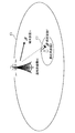
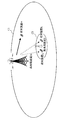
- FIG. 1 shows a configuration example of a communication system according to the first embodiment of the present invention.
- a macro cell C1 that covers a wide area (communication in a wide area) and a femto cell C2 that covers a narrow area in the macro cell C1.
- the macro cell C1 includes a base station apparatus M and one terminal apparatus m, and transmits a desired signal from the base station apparatus M to the terminal apparatus m.
- the femtocell C2 includes a base station apparatus F and one terminal apparatus f, and transmits a desired signal from the base station apparatus F to the terminal apparatus f.
- a desired signal addressed to the terminal device m is received as an interference signal from the base station device M, but the transmission power of the base station device F is smaller than the transmission power of the base station device M.
- the reception SINR (Signal to Interference plus Noise power Ratio) in the terminal device f is significantly degraded.
- the base station apparatus in the macro cell C1 is also called MeNB (Macro eNodeB), and the base station apparatus in the femto cell C2 is also called HeNB (Home eNodeB).
- the macro cell C1 and the femto cell C2 are assumed as an example, but the cell combination may be a plurality of cells having different zone radii and a desired signal in one cell interferes with another cell. What is necessary is just to target the cell and zone comprised by a light projection base station (RRE: Remote Radio Equipments), a pico cell (PeNB: Pico eNodeB), a hot spot, a relay station, etc. Furthermore, this embodiment is applicable also in the situation where a terminal device is located in the cell edge of two or more adjacent macrocells.
- RRE Remote Radio Equipments
- PeNB Pico eNodeB
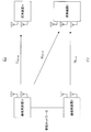
- FIG. 2 shows a detailed example of this system configuration.
- the base station apparatus M has two transmission antennas
- the terminal apparatus m has two reception antennas
- two streams of signals are transmitted from the base station apparatus M to the terminal apparatus m by SU-MIMO (Single User-MIMO).
- the propagation path matrix between the base station apparatus M and the terminal apparatus m is set to HM ⁇ m .
- SU-MIMO transmission is performed in the macro cell C1
- MU-MIMO Multi User-MIMO
- the terminal device m is located at a point sufficiently away from the femtocell, and interference from the femtocell C2 is not considered.
- the base station apparatus F has two transmission antennas, and the terminal apparatus f has three reception antennas.
- the propagation path matrix between the base station apparatus F and the terminal apparatus f is set to HF ⁇ f .
- the propagation path matrix between the base station apparatus M and the terminal apparatus f is set to HM ⁇ f, and a desired signal addressed to the terminal apparatus m from the base station apparatus M passes through the propagation path matrix HM ⁇ f , whereby the terminal The device f receives the interference signal.
- the base station apparatus M and the base station apparatus F are connected by a wired network (in the case of a relay, they may be connected wirelessly), and information can be shared between the base station apparatuses MF.
- a general light-extending base station or picocell base station exchanges information with the base station apparatus M via an optical fiber or a dedicated network
- the femtocell base station F has an ADSL (Asymmetric Digital Subscriber Line) or an optical fiber.
- the mobile phone is connected to the Internet and exchanges information with the base station apparatus M via the Internet.
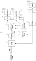
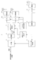
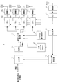
- FIG. 3 shows the configuration of the base station apparatus M according to this embodiment.
- a transmission filter W TX (m) for SU-MIMO transmission to the terminal m is calculated and precoding is performed.
- the terminal apparatus m notifies the base station apparatus M in advance of the channel matrix H M ⁇ m estimated from the pilot signal and the stream number information R m .
- R m 2.
- the reception antenna AT1 receives a signal transmitted from the terminal device m and outputs the signal to the radio unit 1.
- the radio unit 1 down-converts the reception signal input from the reception antenna AT1 to generate a baseband signal, and outputs the baseband signal to an A / D (Analog to Digital) unit 3.
- the A / D unit 3 converts the input analog signal into a digital signal and outputs it to the receiving unit 5.
- the receiving unit 5 extracts the propagation path matrix H M ⁇ m and the stream number information R m from the input digital signal, the propagation path matrix H M ⁇ m is used as the transmission filter calculation unit 7, and the stream number information R m is used as the upper layer. 11 to output.
- the stream number information R m is notified to the base station apparatus F via a wired network.
- it is assumed to notify it base station apparatus F and R m fed back from the terminal m.
- the stream number information R m herein will denote one certain resources the number of streams to be spatially multiplexed in (frame, slot, also called a resource block).
- the transmission filter calculation unit 7 calculates a transmission filter W TX (m) from the propagation path matrix H M ⁇ m input from the reception unit 5.
- the transmission filter W TX (m) is a filter for performing precoding in the base station apparatus M, but it is only necessary to realize transmission of the stream number information R m from the base station apparatus M to the terminal apparatus m.
- Any filter may be used.
- a ZF (Zero Forcing) filter represented by Expression (1) is used as an example of a transmission filter that spatially multiplexes two streams.
- precoding may be performed so that eigenmode transmission is performed using a transmission / reception filter obtained by performing singular value decomposition (SVD) on the channel matrix HM ⁇ m .
- SVD singular value decomposition
- a configuration may be adopted in which any one of a plurality of predetermined transmission filter candidates called a codebook is selected, and signals corresponding to the number of streams are spatially multiplexed using the selected transmission filter and transmitted.
- a configuration since it is SU-MIMO transmission, a configuration may be employed in which a plurality of streams are separated by transmitting without performing precoding and performing MMSE (Minimum Mean Square Error) reception or the like on the terminal side.
- MMSE Minimum Mean Square Error
- the upper layer 11 generates transmission information symbol d m of the stream number information R m min input from the receiving unit 5, and outputs to modulation section 15.
- the modulation unit 15 modulated by the transmission data signal s m using a modulation scheme such as QPSK transmission information symbol d m (Quadrature Phase Shift Keying) and 16QAM (Quadrature Amplitude Modulation), and outputs to the transmission filter multiplier 17 .
- the transmission filter multiplier 17 multiplies the transmission data signal s m by the transmission filter W TX (m) and performs precoding processing to generate the transmission signal x m as shown in Expression (2).
- the transmission power in the base station apparatus M such as the maximum transmission power per transmission antenna
- the expression (in order to make the power of the transmission signal x m after precoding processing equal to or less than the limit value) the signal multiplied by some coefficients x m 2) there is a case where the transmission signal, but here for simplicity of explanation, it is assumed that no consideration is given to factors that limit the transmission power.
- the base station apparatus M multiplexes and transmits the transmit signal x m a pilot signal for channel estimation for demodulation of the data signal.
- the pilot signal for propagation path estimation is used to estimate the equivalent propagation path H M ⁇ m W TX (m) in the terminal device m. Therefore, the base station apparatus M transmits a signal obtained by multiplying a known pilot signal by the transmission filter W TX (m), and causes the terminal apparatus m to estimate the equivalent channel matrix H M ⁇ m W TX (m) .
- a ZF filter is used as a transmission filter, and two transmission data are received in a separated state. Therefore, an equivalent channel matrix H M ⁇ m W TX (m) is not necessarily estimated.
- the pilot signal generation unit 21 generates a known pilot signal and outputs it to the transmission filter multiplication unit 17.
- the transmission filter multiplier 17 multiplies the transmit filter W TX (m) to the input known pilot signal, and outputs it to the D / A (Digital to Analog) unit 23a ⁇ 23b together with the transmission signal x m.
- the D / A units 23a and 23b convert the multiplexed signal from a digital signal to an analog signal, and the radio units 25a and 25b up-convert the input analog signal to a radio frequency, via the transmission antennas AT2 and AT3. Then, a signal is transmitted to the terminal device m.
- the base station apparatus M in the present embodiment also transmits a pilot signal for causing the terminal apparatus m to estimate the propagation path matrix H M ⁇ m .
- this pilot signal is not multiplied by a transmission filter. Therefore, the known pilot signal generated by the pilot signal generation unit 21 is output to the D / A 23a / 23b and transmitted from the transmission antennas AT2 / AT3 via the radio units 25a / 25b.
- the pilot signal for estimating the propagation path matrix H M ⁇ m does not need to be multiplexed with the data signal or the like, and may be transmitted at different time timings (frames).
- pilot signals transmitted from the transmission antennas AT2 and AT3 are transmitted using orthogonal time resources or the like so that the reception side does not interfere with each other.
- pilot signals may be transmitted from the transmission antennas AT2 and AT3 using different subcarriers. Further, a configuration may be adopted in which each pilot signal is multiplied by an orthogonal code to generate and transmit an orthogonal pilot signal.
- the signal x m transmitted from the base station apparatus M to the terminal apparatus m passes through the propagation path HM ⁇ m , and the terminal apparatus m receives the signal of Expression (3). However, in order to simplify the explanation, the noise component added in the terminal device m is ignored.
- FIG. 4 shows a configuration of the terminal device m according to the present embodiment.
- the reception antennas AT4 and AT5 receive signals transmitted from the base station apparatus M, and the radio units 31a and 31b downconvert the reception signals input from the reception antennas AT4 and AT5 to generate baseband signals.
- the A / D units 33 a and 33 b convert the input analog signal into a digital signal and output it to the signal separation unit 35.
- the signal separation unit 35 separates the input signal into a propagation path estimation pilot signal and reception data, the propagation path estimation pilot signal to the propagation path estimation unit 37, and the reception data to the demodulation unit 41. Output.
- the propagation path estimation unit 37 estimates the equivalent propagation path matrix H M ⁇ m W TX (m) based on the pilot signal added to the data signal and transmitted, and inputs it to the demodulation unit 41. As described above, in the present embodiment, since precoding using a ZF filter is performed in the base station apparatus M, the equivalent channel matrix H M ⁇ m W TX (m) is not necessarily estimated. Although it is not necessary to use for demodulation, this estimation is required when the demodulation unit 41 performs processing using an equivalent channel matrix such as MMSE reception. The demodulator 41 demodulates the received data input from the signal separator 35 and outputs the demodulated data to the upper layer 43.
- the propagation path estimation unit 37 estimates the propagation path matrix H M ⁇ m based on the known pilot signal generated by the pilot signal generation unit 21 of FIG.
- the transmission unit 45 converts the propagation path matrix HM ⁇ m into a transmittable format
- the D / A unit 47 converts the digital signal into an analog signal, and then transmits from the transmission antenna unit AT6 to the base station apparatus via the radio unit 51. Send to M.
- the terminal device f receives the desired signal from the base station device F and the interference from the macro cell C1. Therefore, the femtocell C2 performs the following processing in order to receive a desired signal without being affected by interference from the macrocell C1.
- a reception filter for removing interference from the macro cell C1 is calculated, and a desired signal is extracted by multiplying the reception signal by this reception filter. Also, determine the number of transmission streams to the terminal device f on the basis of the stream number information R m between the base station apparatus M (receiving antenna number information of the terminal device f) the information notified from the base station apparatus F the terminal device f To do. Further, the base station apparatus F determines a transmission filter using information related to the propagation path notified from the terminal apparatus f and information related to the reception filter, and performs precoding.
- FIG. 5 shows a configuration example of the base station apparatus F according to the present embodiment.
- the reception antenna AT11 receives the signal transmitted from the terminal device f, the radio unit 61 down-converts the reception signal input from the reception antenna AT11 to generate a baseband signal, and the A / D unit 63
- the input analog signal is converted into a digital signal and output to the receiver 65.
- the receiving unit 65 extracts information notified from the terminal device f from the input digital signal. Specifically, the propagation path matrix H F ⁇ f , the reception antenna number information N f of the terminal apparatus f, and the reception filter W RX (f) of the terminal apparatus f are extracted, and the propagation path matrix H F ⁇ f and the reception filter W are extracted.
- RX (f) is the transmission filter estimator 67, and outputs a reception antenna number information N f to the stream number decision unit 71.
- the channel matrix H F ⁇ f and the receive filter W RX equivalent channel obtained by multiplying the (f) H F ⁇ f W fed back RX (f), the base station apparatus F It is good also as a structure which extracts an equivalent propagation path. Further, the reception antenna number information N f does not need to be periodically notified, and may be configured to be notified only once when the terminal device f is initially connected to the base station device F.
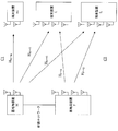
- the number of streams R F to be transmitted from the base station apparatus F to the terminal apparatus f is determined by the formula (4) in the stream number determination unit 71 based on the information fed back in this way. Output to the upper layer.
- R m is the number of streams transmitted from the base station apparatus M to the terminal apparatus m.
- this information can be shared via a wired network to which the base station apparatus M and the base station apparatus F are connected. it can. In this embodiment, it is assumed that the base station apparatus M notifies the base station apparatus F in advance.
- R F ⁇ 3 and a maximum of 3 streams of SU-MIMO transmission is performed in the femtocell.
- R F 0, and in this case, the femto cell does not perform transmission using the same frequency channel as the macro cell.
- the number of reception antennas is equal to or greater than the sum of the number of interferences and the number of desired streams. This is because the condition needs to be satisfied, and in the present embodiment, this is determined by equation (4).
- the number of femtocell transmission streams is adjusted based on the number of macrocell interferences. However, the number of streams to be transmitted within the femtocell (streams) may be satisfied as long as the relationship of Equation (4) is satisfied.
- the base station apparatus F notifies the base station apparatus M of information about the number of streams desired to be transmitted in the base station apparatus F and the number of reception antennas of the terminal apparatus f from the base station apparatus F via the wired network.
- the base station apparatus M determines the number of macro cell transmission streams using Equation (4). Further, the base station apparatus F may determine the number of transmittable streams of the macro cell and notify the base station apparatus M of the information.
- the number of reception antennas of the femtocell terminal is equal to or greater than the sum of the number of interferences and the number of desired streams.
- the number of streams in the femtocell may be determined using a formula different from 4).
- the transmission filter calculation unit 67 calculates the transmission filter W TX (f) from the propagation path matrix H F ⁇ f notified from the terminal device f and the reception filter W RX (f) as shown in Expression (5).
- the transmission filter W TX (f) is a transmission filter for performing precoding in the base station apparatus F.
- the modulation unit 75 and a transmission data signal s f modulates transmission information symbol d f, and outputs to the transmission filter multiplier unit 77.
- the transmission filter multiplier 77 multiplies the transmission data signal s f by the transmission filter W TX (f) and performs precoding processing for generating the transmission signal x f as shown in the equation (6).
- equation (6) as in equation (2), the coefficient for limiting the transmission power in some cases as a transmission signal a signal obtained by multiplying the x f, where is not considered.
- the pilot signal generator 81 generates a known pilot signal and outputs it to the transmission filter multiplier 77.
- the transmission filter multiplier unit 77 multiplies the transmit filter W TX (f) to the input known pilot signal, and outputs it to the D / A unit 83a ⁇ 83 b together with the transmission signal x f.
- the D / A sections 83a and 83b convert the multiplexed signal from a digital signal to an analog signal, and the radio sections 85a and 85b up-convert the input analog signal to a radio frequency, via the transmission antennas AT12 and AT13.
- the base station apparatus F in the present embodiment also transmits a pilot signal for causing the terminal apparatus f to estimate the propagation path matrix H F ⁇ f .
- This pilot signal is the same as the pilot signal for estimating the propagation path matrix H M ⁇ m in the base station apparatus M, and the known pilot signal generated by the pilot signal generation unit 81 is output to the D / A 83a and 83b. And transmitted from the transmission antennas AT12 and AT13 via the radio units 85a and 85b.
- the pilot signal for estimating the propagation path matrix H F ⁇ f does not need to be multiplexed with the data signal or the like, and may be transmitted at different time timings (frames). Further, the pilot signals transmitted from the transmitting antennas AT12 and AT13 are transmitted using orthogonal time resources or the like so that the receiving side does not interfere with each other.
- the pilot signal may be transmitted from each transmission antenna using different subcarriers. Further, a configuration may be adopted in which each pilot signal is multiplied by an orthogonal code to generate and transmit an orthogonal pilot signal.
- FIG. 6 shows the configuration of the terminal device f according to the present embodiment.
- the terminal device f receives the signal transmitted from the base station apparatus M of the macro cell prior to the transmission of the desired signal from the base station apparatus F of the femtocell described above, and the radio units 91a, 91b, 91c
- the baseband signal is generated by down-converting the reception signals input from the reception antennas AT14, AT15, and AT16, and the A / D units 93a, 93b, and 93c convert the input analog signals into digital signals and perform signal separation.
- the signal separator 95 separates the pilot signal from the input signal and outputs it to the reception filter calculator 97.
- the reception filter calculation unit 97 estimates an equivalent propagation path H M ⁇ f W TX (m) between the base station apparatus M and the terminal apparatus f from the reception filter calculation pilot signal, and is equivalent to Equation (7).
- Singular value decomposition (SVD: Single Value Decomposition) is performed on the complex conjugate transpose matrix of the propagation path H M ⁇ f W TX (m) .
- the reception filter W RX (f) is a complex conjugate of the right singular vector corresponding to zero in the diagonal component of the singular value matrix D among the right singular vectors V obtained by performing singular value decomposition on the equation (7).
- This is a transposed vector. This is because when the obtained vector is multiplied by the signal transmitted from the macrocell base station M, the signal becomes zero, that is, a vector that can remove the signal arriving from the macrocell base station M is calculated as a reception filter.
- the singular value decomposition of the complex conjugate transposed matrix of equivalent channel H M ⁇ f W TX (m ) equivalent channel H M ⁇ f W TX (m ) a singular value decomposition to receive A filter may be calculated.
- the complex conjugate transposed vector of the left singular vector corresponding to zero in the diagonal component of the singular value matrix D is used as the reception filter.
- the reception filter calculation unit 97 outputs the calculated reception filter W RX (f) to the reception filter multiplication unit 101 and the transmission unit 103.
- the terminal device f performs propagation channel estimation using a pilot signal transmitted from the base station device F for estimating the propagation channel matrix H F ⁇ f .
- the propagation path estimation unit 105 estimates the propagation path matrix H F ⁇ f based on the known pilot signal generated by the pilot signal generation unit 21 of FIG.
- the transmission unit 103 converts the propagation path matrix H F ⁇ f , the reception filter W RX (f) , and the reception antenna number information N f into a transmittable format, and the D / A unit 107 converts the digital signal into an analog signal. Then, transmission is performed from the transmission antenna unit AT17 to the base station apparatus F via the radio unit 109. Through such processing, information necessary for the base station apparatus F is fed back from the terminal apparatus f. However, as mentioned earlier, the number of reception antennas information N f need not be sent periodically.
- the number of streams to be transmitted is determined based on the stream number information R m notified from the base station apparatus M of the macro cell and the reception antenna number information N f fed back from the terminal apparatus f.
- the received signal when the terminal device f receives the data signal transmitted from the base station apparatus F by the precoding of the data signal is expressed by Expression (8).
- the noise component added in the terminal device f is ignored.
- the received signal y f includes the components of the desired signal x f transmitted from the base station apparatus F and the components of the interference signal transmitted from the base station apparatus M to the terminal apparatus m. It is expressed as a sum.
- the propagation path matrix H F ⁇ f is a propagation path between the base station apparatus F and the terminal apparatus f
- the propagation path H M ⁇ f is a propagation path between the base station apparatus M and the terminal apparatus f.
- the reception antennas AT14, AT15, and AT16 receive the signal of Expression (8), and the radio units 91a, 91b, and 91c down-convert the reception signals input from the reception antennas AT14, AT15, and AT16, and convert the baseband signal. Then, the A / D units 93 a, 93 b, and 93 c convert the input analog signals into digital signals and output them to the signal separation unit 95.
- the signal separation unit 95 separates the input signal into an equivalent propagation path matrix H F ⁇ f W TX (f) estimation pilot signal and received data, and the equivalent propagation path matrix H F ⁇ f W TX (f).
- the pilot signal for estimation is output to propagation path estimation section 105, and the received data is output to reception filter multiplication section 101.
- (alpha) is a real number and represents an equivalent amplitude gain.
- the reception filter W RX (f) is determined so that the interference component (HM ⁇ f W TX (m) s m ) from the macro cell can be removed.
- the interference component term (W RX (f) H M ⁇ f W TX (m) s m ) becomes zero and the interference component is removed.
- the desired signal from the femto cell since the consideration of the receive filter W RX in the calculation of the transmit filter W TX in the base station apparatus F (f) (f), multiplies the receive filter W RX (f)
- the desired signal s f can be extracted.
- the equivalent channel matrix H F ⁇ f W TX (f) estimated by the channel estimation unit 105 and the reception filter W RX It is also possible to calculate ⁇ in consideration of f) and divide the signal shown in equation (9) by ⁇ .
- a desired signal is extracted using the reception filter W RX (f) previously calculated by the reception filter as it is.
- the demodulator 111 demodulates the desired signal s f input from the reception filter multiplier 101 and outputs it to the upper layer 113.
- the number of transmission streams in the macro cell and the transmission in the femto cell according to the number of transmission streams in the macro cell that is a very large interference source for the femto cell and the degree of freedom (number of reception antennas) of the terminal device in the femto cell.
- the terminal device in the femtocell receives a desired signal while removing interference coming from the macrocell. It becomes possible.
- the transmission filter W TX (f) is calculated based on the equation (5).
- a selection called a code book is used for the purpose of reducing the amount of control information.
- Possible transmission filter matrix candidates can be predefined in the system, and one matrix can be selected from among them, which maximizes the transmission characteristics.
- the selection criterion in the case of using the code book in the present embodiment is a criterion for maximizing the expression (10), and the matrix thus selected is generally used as the transmission filter W TX (f). Is possible.
- the terminal device f receives large interference from the macro cell
- the terminal device m is located in the vicinity of the femto cell, but the macro cell terminal device m is separated from the femto cell.
- the base station apparatus M and the base station apparatus F may share the number-of-streams information and perform the processing as described above even when located at a place. This is because the macro cell base station apparatus grasps the position of the femto cell in advance, further grasps the current position of the terminal apparatus m by a GPS function or the like, and the terminal apparatus m detects a predetermined threshold value from the femto cell.
- the terminal device m receives the signal transmitted from the femtocell and measures the level thereof, thereby knowing how far the terminal device m is located from the femtocell.
- the configuration shown in this embodiment may be performed only for femtocells close to the base station apparatus M. This is because, in the femtocell close to the base station apparatus M, the reception characteristics are remarkably deteriorated due to the influence of the signal transmitted from the base station apparatus M. Therefore, the effect of performing the interference removal by the linear filter shown in this embodiment is effective. This is because it is very large. Thus, when switching on / off of this embodiment according to the position of the base station apparatus M and the femtocell, when the femtocell is installed, the user notifies the operator of the position and registers it.
- the operator knows the distance to the macro cell base station apparatus M, and if it is very close, notifies the femto cell of that fact, thereby enabling the processing according to the present embodiment to be turned on.
- the femtocell itself can grasp the positional relationship between the macrocell and the femtocell by using the GPS function or the femtocell measuring the interference level from the macrocell. Can be switched.
- FIG. 7 shows a configuration of a communication system according to the second embodiment of the present invention.
- the macro cell C1 has the same configuration as that of the first embodiment, and the femtocell C3 has a base station apparatus F and two terminal apparatuses f 1 and f 2 that perform MU-MIMO transmission. Do.
- the terminal devices f 1 and f 2 receive the desired signal addressed to the terminal device m from the base station device M as an interference signal.
- the macro cell C1 and the femto cell C3 are assumed as an example, but a plurality of cells having different zone radii, and a combination of cells in which a desired signal in one cell interferes with another cell.
- Any cell or zone including a light projecting base station, a pico cell, a hot spot, a relay station, or the like may be used. Furthermore, this embodiment is applicable also in the situation where a terminal device is located in the cell edge of two or more adjacent macrocells.
- FIG. 8 shows details of the system configuration of this embodiment.
- the macro cell C1 base station apparatus M, terminal apparatus m
- the base station apparatus F has four transmission antennas
- the terminal apparatus f 1 and the terminal apparatus f 2 have four reception antennas.
- the channel matrix between the channel matrix between the base station apparatus F and the terminal device f 1 of H F ⁇ f1 of H F ⁇ f1 the base station apparatus F and the terminal device f 2 and H F ⁇ f2.
- the propagation path matrix between the base station apparatus M and the terminal apparatus f 1 is H M ⁇ f 1
- the propagation path matrix between the base station apparatus M and the terminal apparatus f 2 is H M ⁇ f 2
- the base station apparatus M The desired signal addressed to the terminal device m is received as an interference signal in the terminal devices f 1 and f 2 by passing through these propagation paths H M ⁇ f1 and H M ⁇ f2 .
- the base station apparatus M and the base station apparatus F are connected by a wired network (in the case of a relay, they may be connected wirelessly), and information can be shared between the base station apparatuses MF. .
- a wired network in the case of a relay, they may be connected wirelessly
- information can be shared between the base station apparatuses MF.
- the base station apparatus M via an optical fiber or a dedicated network
- the femtocell base station F is connected to the Internet via ADSL or optical fiber
- Information is often exchanged with the base station apparatus M via the Internet.
- the base station apparatus M and the terminal apparatus m in this embodiment are the same as those shown in FIGS.
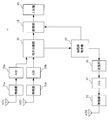
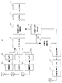
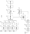
- FIG. 9 shows the configuration of the base station apparatus F in the femtocell C3 according to this embodiment.
- the difference between the transmission systems is that the number of D / A sections 83a to 83d, radio sections 85a to 85d, and transmission antennas AT12, AT13, AT21, and AT22 are increased compared to the configuration shown in FIG. It is.
- the base station apparatus F receives the information notified from the terminal apparatuses f 1 and f 2 and extracts the notified information.
- the wireless unit 61 In the receiving antenna AT11, and receives a signal transmitted from the terminal device f 1, the wireless unit 61 generates a baseband signal by down-converts the received signal input from the reception antenna AT11, A / D 63 The input analog signal is converted into a digital signal and output to the receiving unit 65.
- the receiving unit 65 extracts information notified from the terminal device f 1 from the input digital signal.
- the channel matrix H F ⁇ f1 extracts the receive filter W RX terminal device f (f1), the channel matrix H F ⁇ f1 and the reception filter W RX (f 1) is output to transmission filter calculation section 127 and reception antenna number information N f is output to stream number determination section 71.
- the terminal device f 2 extracts the information notified from the terminal apparatus f 2, the channel matrix H F ⁇ f2 and the reception filter W RX and (f2) to the transmitting filter calculating section 67, the receiving antenna number information N f1 is output to the stream number determination unit 71.
- the base station apparatus F may extract the equivalent propagation path by feeding back the multiplication result (equivalent propagation path) of the propagation path matrix and the reception filter.
- reception antenna number information does not need to be periodically notified from the terminal apparatuses f 1 and f 2 to the base station apparatus F, and may be configured to be notified only once at the initial connection to the base station apparatus F.
- the number-of-streams determination unit 71 determines the number of streams R F1 and R F2 to be transmitted from the device F to the terminal devices f 1 and f 2 so as to satisfy the condition of Expression (11).
- R F R F1 + R F2
- R m is the number of streams to be transmitted from the base station apparatus M to the terminal apparatus m.
- the R m is transmitted between the base station apparatuses using a method such as connecting the base station apparatus M and the base station apparatus F by wire. Information is shared so that the base station apparatus M notifies the base station apparatus F in advance.
- N F is the number of transmission antennas of the base station apparatus F.
- the stream number R F1 to the terminal device f 1 is the receive antenna number terminal f 1, so as to be less than the result of subtracting the number of interference from the base station apparatus M It means that it is calculated. This is due to the condition that the number of reception antennas is equal to or greater than the sum of the number of interferences and the number of desired streams, as in the first embodiment.
- the second equation of Formula (11) as a result of the stream number R F2 addressed to the mobile station f 2 is from the number of receiving antennas terminal f 2, obtained by subtracting the number of interference from the base station apparatus M It is calculated to be as follows. This is also due to the condition that the number of reception antennas is equal to or greater than the sum of the number of interferences and the number of desired streams, as in the first embodiment.
- the third equation of Equation (11) represents that the total number of streams R F in the femtocell C3 is equal to or less than the number of transmission antennas of the base station apparatus F.
- the number of streams to be transmitted to the respective terminal devices is determined only by the first formula and the second formula, the total is larger than the number of transmission antennas of the base station device F, and actually the transmission of such number of streams is performed. It is possible that a situation where it is not possible to occur, but the third equation can be said to be an equation representing a restriction for avoiding such a situation.
- Equation (11) represents the calculation conditions for the number of streams that can be received from the base station apparatus F while the terminal apparatus f 1 and the terminal apparatus f 2 receive interference from the base station apparatus M, respectively. Yes.
- the number of streams may be calculated using another formula.
- R F1 ⁇ 1 and R F2 ⁇ 1 are set first, and this result also always satisfies the third formula in the formula (11).
- R F1 ⁇ 1 and R F2 ⁇ 1 are set. Control is performed so as to calculate a combination of R F1 and R F2 to be satisfied.
- (R F1 , R F2 ) (1, 1).
- the number of streams addressed to each terminal device determined in this way is output from the stream number determination unit 71 to the upper layer.
- the base station apparatus F performs MU-MIMO transmission for transmitting two streams to each terminal apparatus.
- the calculation method of a transmission filter is demonstrated by taking this case as an example.
- the transmission filter calculation unit 67 As shown in Expression (12), the propagation path matrices H F ⁇ f1 and H F ⁇ f2 notified from each terminal device, and reception filters W RX (f1) and W RX (f2 ) To calculate the transmission filter W TX (f) .
- the transmission filter W TX (f) is a transmission filter for performing precoding for the number of transmission streams in the base station apparatus F.
- the transmission filter W TX (f) in Expression (12 ) is a ZF filter. That is, in the present embodiment, MU-MIMO transmission is performed in which two streams are transmitted from the base station apparatus F to each terminal apparatus, but each stream is transmitted to each terminal apparatus by using the transmission filter of Equation (12). This is a method of receiving with a different antenna.
- BD Block Dialogization
- the terminal device receives a plurality of two streams with a plurality of antennas.
- the transmission filter is calculated using singular value decomposition as follows.
- V f1 ′ is a filter for directing null from the base station apparatus F to the terminal apparatus f 1
- V f2 ′ is a filter for directing null from the base station apparatus F to the terminal apparatus f 2 .
- V f1 ′ and V f2 ′ are both 4-by-2 matrices.
- Equation (15) a singular value decomposition to 'a vector which can multiply the V f1' right singular vector V f11 obtained from the right V f2 and 'the V f1' right singular vector V f22 from the right
- the transmission filter W TX (f) in the case of using BD is expressed by Equation (15).
- V f11 and V f22 is a matrix of the respective two rows and two columns
- a V f1 '' and V f2 '' are the 4 2 matrix.
- the reception processing in this embodiment removes interference signals coming from the macro cell using the reception filter W RX (f) calculated by performing singular value decomposition on the equivalent propagation path in each terminal device.
- the base station device F to the left singular vectors U f11 of formula (14) to the terminal device f 1, and notifies the left singular vectors U f22 to the terminal f 2, each the signal after the receive filter W RX (f) multiplying the terminal device, by multiplying the U f11, U f22 respectively, to separate the plurality of streams which are transmitted to each terminal device (separating SU-MIMO transmission) configuration It is good.
- this U f11, U f22 is also possible to estimate in each terminal device.
- the modulation unit 75 and a transmission data signal s f modulates transmission information symbol d f, and outputs to the transmission filter multiplier unit 77.
- Subsequent processing of the base station apparatus F is the same as that of the first embodiment.
- the transmission signal is multiplied by the transmission filter calculated by the transmission filter calculation unit 77, and the pilot signal generated by the pilot signal generation unit 81 is added.
- the data is transmitted from the AT12 / AT13 / AT21 / AT22 via the D / A units 83a / 83b / 83c / 83d and the wireless units 85a / 85b / 85c / 85d.
- a transmission filter is calculated by the ZF method or the like described above.
- MU-MIMO transmission is performed for each stream from the base station apparatus F to each terminal apparatus using the transmitted filter.
- R m 3
- a signal may be transmitted only to one of the terminal devices f 1 and f 2 instead of the MU-MIMO transmission.
- a transmission filter can be obtained by the ZF or BD method described above. Can be calculated.
- the maximum number of streams that can be transmitted to one terminal apparatus needs to be set to 3 because the degree of freedom of the terminal apparatus is consumed to remove the interference signal coming from the macro cell.
- FIG. 10 shows a configuration of the terminal device f 1 (f 2 ) according to the present embodiment.
- the difference in the reception system is that the number of reception antennas AT14, AT15, AT16, and AT23, the radio units 91a to 91d, and the A / D units 93a to 93d are increased compared to the configuration shown in FIG. It is.
- the number of reception antennas is four (AT14 / AT15 / AT16 / AT23), and the radio units 91a, 91b, 91c, and 91d and the A / D units 93a, 93b, 93c, and 93d are used.
- the received signal is input to the signal separation unit 95.
- the processing in each terminal device is the same as in the first embodiment.
- the reception signal is separated into reception data and a pilot signal, and the reception filter multiplication unit 101 multiplies the reception data by the reception filter W RX (f) to extract the transmission signal.
- the reception filter W RX (f) is calculated in advance using Expression (7) as in the first embodiment.
- propagation path estimation section 105 estimates propagation path H F ⁇ f from the propagation path estimation pilot signal, and feeds back to base station apparatus F together with reception filter W RX (f) and reception antenna number information N f. To do.
- one terminal apparatus When the base station apparatus F performs precoding by BD, one terminal apparatus is obtained by multiplying the complex conjugate transposed vector of the left singular vector of Expression (14) after multiplication by the reception filter WRX (f). Multiple streams sent to the destination can be separated.
- the propagation path estimation unit 105 estimates the equivalent propagation path, and the reception filter multiplication unit 101 multiplies the reception data signal by the reception filter calculated based on the estimation result. Streams can be separated and extracted.
- the number of transmission streams in the femtocell is determined by determining the number of transmission streams in the femtocell so that the sum of the number of transmission streams in the macrocell and the number of transmission streams in the femtocell does not exceed the degree of freedom of the terminal device.
- the desired signal can be received while removing the interference coming from the macro cell.
- the degree of freedom of the terminal device can be achieved by aligning the interference from the macro cell with the equivalent channel vector of the inter-user interference in the femto cell. These interferences can be efficiently eliminated within the range.
- the base station apparatus F performs precoding using the transmission filter W TX (f) of Expression (16). However, in this case, the base station apparatus F needs to grasp the transmission filter W TX (m) in the base station apparatus M, but this can be acquired from the base station apparatus M through a wired network.
- the equivalent propagation paths H M ⁇ f1 W TX (m) and H M ⁇ f2 W TX (m) are estimated and fed back to the base station apparatus F, respectively. It is good.
- the propagation path and the reception filter estimated by each terminal apparatus are fed back to the base station apparatus F, and each terminal apparatus uses the same reception filter as the notified reception filter.
- the reception filter based on the MMSE standard may be calculated instead of the reception filter.
- the weight of the MMSE filter in each terminal device is expressed as in Expression (17).
- H F ⁇ f W TX (f) in Expression (17) is an equivalent propagation path estimated from the pilot signal for reception filter calculation by the reception filter calculation unit 97.
- ⁇ 2 represents the reciprocal of average received SNR (or noise variance).
- the base station apparatus of the femtocell that has acquired information on the number of transmission streams in the macro cell determines the number of streams to be transmitted by itself is shown.
- the centralized control station acquires information on the number of transmission streams in the macro cell and information on the number of reception antennas of the terminal of the femto cell, and a stream transmitted by the base station apparatus of the femto cell based on them. The number may be determined.
- a program for realizing the functions described in the present embodiment is recorded on a computer-readable recording medium, and the program recorded on the recording medium is read into a computer system and executed to execute processing of each unit. May be performed.
- the “computer system” here includes an OS and hardware such as peripheral devices.
- the “computer system” includes a homepage providing environment (or display environment) if a WWW system is used.
- the “computer-readable recording medium” means a storage device such as a flexible disk, a magneto-optical disk, a portable medium such as a ROM and a CD-ROM, and a hard disk incorporated in a computer system. Furthermore, the “computer-readable recording medium” dynamically holds a program for a short time like a communication line when transmitting a program via a network such as the Internet or a communication line such as a telephone line. In this case, a volatile memory in a computer system serving as a server or a client in that case, and a program that holds a program for a certain period of time are also included.
- the program may be a program for realizing a part of the above-described functions, or may be a program that can realize the above-described functions in combination with a program already recorded in a computer system.
- the present invention can be used for communication devices.
Landscapes
- Engineering & Computer Science (AREA)
- Computer Networks & Wireless Communication (AREA)
- Signal Processing (AREA)
- Mobile Radio Communication Systems (AREA)
Priority Applications (1)
| Application Number | Priority Date | Filing Date | Title |
|---|---|---|---|
| US13/984,900 US20130324136A1 (en) | 2011-02-17 | 2012-01-31 | Communication system, base station apparatuses, and terminal devices |
Applications Claiming Priority (2)
| Application Number | Priority Date | Filing Date | Title |
|---|---|---|---|
| JP2011032556A JP5703057B2 (ja) | 2011-02-17 | 2011-02-17 | 通信システム、基地局装置、端末装置 |
| JP2011-032556 | 2011-02-17 |
Publications (1)
| Publication Number | Publication Date |
|---|---|
| WO2012111419A1 true WO2012111419A1 (ja) | 2012-08-23 |
Family
ID=46672355
Family Applications (1)
| Application Number | Title | Priority Date | Filing Date |
|---|---|---|---|
| PCT/JP2012/052066 Ceased WO2012111419A1 (ja) | 2011-02-17 | 2012-01-31 | 通信システム、基地局装置、端末装置 |
Country Status (3)
| Country | Link |
|---|---|
| US (1) | US20130324136A1 (enExample) |
| JP (1) | JP5703057B2 (enExample) |
| WO (1) | WO2012111419A1 (enExample) |
Cited By (1)
| Publication number | Priority date | Publication date | Assignee | Title |
|---|---|---|---|---|
| US20140269409A1 (en) * | 2013-03-14 | 2014-09-18 | Telefonaktiebolaget L M Ericsson (Publ) | Explicit signaling of number of receiver antennas |
Families Citing this family (5)
| Publication number | Priority date | Publication date | Assignee | Title |
|---|---|---|---|---|
| WO2014189421A1 (en) * | 2013-05-23 | 2014-11-27 | Telefonaktiebolaget L M Ericsson (Publ) | Method and network node for assisting handling of interference at a receiver device |
| WO2016002087A1 (ja) * | 2014-07-04 | 2016-01-07 | 富士通株式会社 | 通信システム、基地局及び基地局制御方法 |
| US10897285B2 (en) * | 2017-02-15 | 2021-01-19 | Qualcomm Incorporated | Distributed multi-user (MU) wireless communication |
| US10588151B2 (en) | 2017-07-12 | 2020-03-10 | Qualcomm Incorporated | Spatial listen before talk by precoded request to send and clear to send via whitening |
| KR102176730B1 (ko) * | 2019-01-23 | 2020-11-10 | 주식회사 지씨티리써치 | Qr 분해와 mmib 메트릭을 이용한 채널 상태 정보 추출 방법 및 mimo 수신기 |
Citations (3)
| Publication number | Priority date | Publication date | Assignee | Title |
|---|---|---|---|---|
| WO2009120048A2 (en) * | 2008-03-28 | 2009-10-01 | Lg Electronics Inc. | Method for avoiding inter-cell interference in a multi-cell environment |
| JP2010522516A (ja) * | 2007-03-23 | 2010-07-01 | クゥアルコム・インコーポレイテッド | 干渉管理のためのバックホール通信 |
| JP2010278674A (ja) * | 2009-05-27 | 2010-12-09 | Kyocera Corp | 無線通信システム、無線端末及び無線通信方法 |
Family Cites Families (10)
| Publication number | Priority date | Publication date | Assignee | Title |
|---|---|---|---|---|
| US8611311B2 (en) * | 2001-06-06 | 2013-12-17 | Qualcomm Incorporated | Method and apparatus for canceling pilot interference in a wireless communication system |
| US7197084B2 (en) * | 2002-03-27 | 2007-03-27 | Qualcomm Incorporated | Precoding for a multipath channel in a MIMO system |
| DE602008001803D1 (de) * | 2008-10-24 | 2010-08-26 | Ntt Docomo Inc | Koordination der Funkressourcenzuteilung in einem Makro-/Mikrozellen-Funkkommunikationssystem |
| EP2377345B1 (en) * | 2009-01-14 | 2015-09-16 | Nec Corporation | Method for interference mitigation for femtocell base stations of a wimax network |
| US8452322B2 (en) * | 2009-02-04 | 2013-05-28 | Lg Electronics Inc. | Method for controlling uplink transmission power in wireless communication system and an apparatus therefor |
| WO2010122749A1 (ja) * | 2009-04-24 | 2010-10-28 | シャープ株式会社 | 通信システム、通信装置および通信方法 |
| KR101324395B1 (ko) * | 2009-04-29 | 2013-11-01 | 인텔 코포레이션 | 코드북 기반 사전코딩 방법, 코드북 기반 폐루프 송신방법 및 프로세서 판독가능 저장매체 |
| KR101615116B1 (ko) * | 2009-07-13 | 2016-04-25 | 삼성전자주식회사 | 펨토 셀 또는 피코셀을 위한 프리코딩 방법 및 상기 방법을 사용하는 통신 시스템 |
| US9072020B2 (en) * | 2009-08-26 | 2015-06-30 | Samsung Electronics Co., Ltd. | Methods and apparatus to support coordinated interference mitigation in multi-tier networks |
| CN102195757B (zh) * | 2010-03-19 | 2014-06-11 | 华为技术有限公司 | 分布式多天线系统中的预编码、解码方法和装置 |
-
2011
- 2011-02-17 JP JP2011032556A patent/JP5703057B2/ja not_active Expired - Fee Related
-
2012
- 2012-01-31 WO PCT/JP2012/052066 patent/WO2012111419A1/ja not_active Ceased
- 2012-01-31 US US13/984,900 patent/US20130324136A1/en not_active Abandoned
Patent Citations (3)
| Publication number | Priority date | Publication date | Assignee | Title |
|---|---|---|---|---|
| JP2010522516A (ja) * | 2007-03-23 | 2010-07-01 | クゥアルコム・インコーポレイテッド | 干渉管理のためのバックホール通信 |
| WO2009120048A2 (en) * | 2008-03-28 | 2009-10-01 | Lg Electronics Inc. | Method for avoiding inter-cell interference in a multi-cell environment |
| JP2010278674A (ja) * | 2009-05-27 | 2010-12-09 | Kyocera Corp | 無線通信システム、無線端末及び無線通信方法 |
Cited By (1)
| Publication number | Priority date | Publication date | Assignee | Title |
|---|---|---|---|---|
| US20140269409A1 (en) * | 2013-03-14 | 2014-09-18 | Telefonaktiebolaget L M Ericsson (Publ) | Explicit signaling of number of receiver antennas |
Also Published As
| Publication number | Publication date |
|---|---|
| US20130324136A1 (en) | 2013-12-05 |
| JP2012175191A (ja) | 2012-09-10 |
| JP5703057B2 (ja) | 2015-04-15 |
Similar Documents
| Publication | Publication Date | Title |
|---|---|---|
| AU2025230741B2 (en) | Systems and methods for radio frequency calibration exploiting channel reciprocity in distributed input distributed output wireless communications | |
| JP7823010B2 (ja) | 無線セルラシステムにおけるセル間多重化利得の利用 | |
| AU2025210786A1 (en) | Systems and methods for exploiting inter-cell multiplexing gain in wireless cellular systems via distributed input distributed output technology | |
| JP5703057B2 (ja) | 通信システム、基地局装置、端末装置 | |
| CN114375545B (zh) | 干扰抑制 | |
| Łukowa et al. | Centralized UL/DL resource allocation for flexible TDD systems with interference cancellation | |
| WO2012172935A1 (ja) | 制御局装置、集中制御局装置、端末装置、通信システム及び通信方法 | |
| JP5897810B2 (ja) | 基地局装置、端末装置、通信システム、通信方法 | |
| L. Tavares et al. | Interference-robust air interface for 5G ultra-dense small cells |
Legal Events
| Date | Code | Title | Description |
|---|---|---|---|
| 121 | Ep: the epo has been informed by wipo that ep was designated in this application |
Ref document number: 12747082 Country of ref document: EP Kind code of ref document: A1 |
|
| WWE | Wipo information: entry into national phase |
Ref document number: 13984900 Country of ref document: US |
|
| NENP | Non-entry into the national phase |
Ref country code: DE |
|
| 122 | Ep: pct application non-entry in european phase |
Ref document number: 12747082 Country of ref document: EP Kind code of ref document: A1 |