WO2012111410A1 - Electric cell system - Google Patents
Electric cell system Download PDFInfo
- Publication number
- WO2012111410A1 WO2012111410A1 PCT/JP2012/051894 JP2012051894W WO2012111410A1 WO 2012111410 A1 WO2012111410 A1 WO 2012111410A1 JP 2012051894 W JP2012051894 W JP 2012051894W WO 2012111410 A1 WO2012111410 A1 WO 2012111410A1
- Authority
- WO
- WIPO (PCT)
- Prior art keywords
- series
- circuit
- protection circuit
- battery system
- units
- Prior art date
Links
Images


Classifications
-
- H—ELECTRICITY
- H02—GENERATION; CONVERSION OR DISTRIBUTION OF ELECTRIC POWER
- H02J—CIRCUIT ARRANGEMENTS OR SYSTEMS FOR SUPPLYING OR DISTRIBUTING ELECTRIC POWER; SYSTEMS FOR STORING ELECTRIC ENERGY
- H02J7/00—Circuit arrangements for charging or depolarising batteries or for supplying loads from batteries
- H02J7/0013—Circuit arrangements for charging or depolarising batteries or for supplying loads from batteries acting upon several batteries simultaneously or sequentially
- H02J7/0014—Circuits for equalisation of charge between batteries
-
- H—ELECTRICITY
- H01—ELECTRIC ELEMENTS
- H01M—PROCESSES OR MEANS, e.g. BATTERIES, FOR THE DIRECT CONVERSION OF CHEMICAL ENERGY INTO ELECTRICAL ENERGY
- H01M50/00—Constructional details or processes of manufacture of the non-active parts of electrochemical cells other than fuel cells, e.g. hybrid cells
- H01M50/50—Current conducting connections for cells or batteries
- H01M50/572—Means for preventing undesired use or discharge
- H01M50/574—Devices or arrangements for the interruption of current
-
- H—ELECTRICITY
- H01—ELECTRIC ELEMENTS
- H01M—PROCESSES OR MEANS, e.g. BATTERIES, FOR THE DIRECT CONVERSION OF CHEMICAL ENERGY INTO ELECTRICAL ENERGY
- H01M2200/00—Safety devices for primary or secondary batteries
-
- H—ELECTRICITY
- H01—ELECTRIC ELEMENTS
- H01M—PROCESSES OR MEANS, e.g. BATTERIES, FOR THE DIRECT CONVERSION OF CHEMICAL ENERGY INTO ELECTRICAL ENERGY
- H01M2220/00—Batteries for particular applications
- H01M2220/20—Batteries in motive systems, e.g. vehicle, ship, plane
-
- Y—GENERAL TAGGING OF NEW TECHNOLOGICAL DEVELOPMENTS; GENERAL TAGGING OF CROSS-SECTIONAL TECHNOLOGIES SPANNING OVER SEVERAL SECTIONS OF THE IPC; TECHNICAL SUBJECTS COVERED BY FORMER USPC CROSS-REFERENCE ART COLLECTIONS [XRACs] AND DIGESTS
- Y02—TECHNOLOGIES OR APPLICATIONS FOR MITIGATION OR ADAPTATION AGAINST CLIMATE CHANGE
- Y02E—REDUCTION OF GREENHOUSE GAS [GHG] EMISSIONS, RELATED TO ENERGY GENERATION, TRANSMISSION OR DISTRIBUTION
- Y02E60/00—Enabling technologies; Technologies with a potential or indirect contribution to GHG emissions mitigation
- Y02E60/10—Energy storage using batteries
-
- Y—GENERAL TAGGING OF NEW TECHNOLOGICAL DEVELOPMENTS; GENERAL TAGGING OF CROSS-SECTIONAL TECHNOLOGIES SPANNING OVER SEVERAL SECTIONS OF THE IPC; TECHNICAL SUBJECTS COVERED BY FORMER USPC CROSS-REFERENCE ART COLLECTIONS [XRACs] AND DIGESTS
- Y02—TECHNOLOGIES OR APPLICATIONS FOR MITIGATION OR ADAPTATION AGAINST CLIMATE CHANGE
- Y02T—CLIMATE CHANGE MITIGATION TECHNOLOGIES RELATED TO TRANSPORTATION
- Y02T10/00—Road transport of goods or passengers
- Y02T10/60—Other road transportation technologies with climate change mitigation effect
- Y02T10/70—Energy storage systems for electromobility, e.g. batteries
Definitions
- the present invention relates to a technical field of a battery system having a power supply circuit in which a plurality of series units each having a plurality of secondary battery cells connected in series are connected in parallel.
- Lithium ion secondary batteries nickel metal hydride batteries, lead batteries and the like are known as chargeable / dischargeable secondary batteries.
- chargeable / dischargeable secondary batteries As an application field of this type of secondary battery, for example, there is a battery system mounted on a system that requires a large amount of power, such as an electric vehicle or a hybrid electric vehicle.
- lithium ion secondary batteries are characterized by high energy density, high input / output density, and long cycle life. Therefore, research and development in this field are actively conducted.
- Battery systems are operated by combining a plurality of secondary battery cells to form a power circuit.
- a power supply circuit used for supplying a large amount of power may be configured by combining series units formed by connecting a plurality of secondary battery cells in series. This configuration has an advantage that an excessive current can be prevented from flowing between battery cells when a problem such as a short circuit occurs in the power supply circuit due to some cause.
- Patent Document 1 discloses a technique for suppressing variations in the current value flowing through each series unit.
- state information is detected for each series unit, and the amount of current flowing through each series unit is controlled based on the detected state information, thereby suppressing variations in current value and enabling the life of the battery system.
- a technique for making it as long as possible is disclosed. Such adjustment of the current amount is performed by a power distribution unit inserted in series in each series unit, and the power distribution unit includes elements such as a variable resistor, a switched capacitor, a DC / DC converter, and a DC chopper, for example. Yes.
- Patent Document 1 it is necessary to provide a power distribution unit and detection means for detecting state information for controlling the power distribution unit on a one-on-one basis with the series unit. Therefore, Patent Document 1 has a problem that the circuit configuration of the battery system is complicated, and it is difficult to realize the battery system at low cost.
- the present invention has been made in view of the above problems, and an object of the present invention is to provide a battery system capable of suppressing current value variation in each series unit at a low cost.
- the battery system of the present invention has a power supply circuit in which n series units each having a plurality of secondary battery cells connected in series are connected in parallel to each other, and an output terminal of the power supply circuit Are connected in series with each other in a battery system that supplies power to the load side via an inverter connected to an output terminal of the first protection circuit. Further, (n-1) second protection circuits connected in series between the positive electrodes of the n series units and capable of variably controlling the resistance value are provided.
- the present invention it is possible to suppress variation in the current value between the series units by variably controlling the resistance value in the (n ⁇ 1) second protection circuits. That is, in Patent Document 1, since it is necessary to provide the second protection circuit on a one-to-one basis with the series unit, a total of n second protection circuits are required. That's it. As described above, according to the present invention, the number of elements constituting the circuit can be reduced, so that the battery system can be downsized at the same time as the cost reduction.
- the resistance value of each of the second protection circuits may be controlled so that variation in the current value flowing through each of the second protection circuits is reduced. For example, by monitoring the current value flowing through each second protection circuit, the variation in the current value is measured, and the resistance value of each second protection resistor is controlled so as to reduce the variation in the obtained current value. To adjust.
- the second protection circuit includes a first circuit in which a first switching unit and a fixed resistor are connected in series, and a second circuit including only the second switching unit. May be connected in parallel.
- the resistance value is variably controlled with a simpler circuit configuration by switching between the first circuit having a resistance value corresponding to the fixed resistance and the second circuit having a resistance value of substantially zero. Can do.
- a capacitor may be connected in parallel to the fixed resistor. Since the battery cells constituting the battery system generate electric power mainly by a chemical reaction, it may be difficult to output sufficient electric power to meet the demand on the load side at the time of starting. In this aspect, by using the power stored in the capacitor in advance at the time of starting the battery system, it is possible to supply power quickly in response to a request from the load side.
- the second protection circuit may comprise a variable resistor connected in series to the (n-1) series units.
- the variable control of the resistance value in the second circuit can be performed with finer accuracy.
- the n series units include at least one master unit and other slave units, and the second protection circuit in the slave unit has an output voltage of the master unit of a predetermined value.
- the resistance value may be variably controlled so that
- the second protection circuit in the slave unit may include a DC / DC converter or a chopper circuit connected in series to the slave unit.
- the present invention it is possible to suppress variation in the current value between the series units by variably controlling the resistance value in the (n ⁇ 1) second protection circuits. That is, in Patent Document 1, since it is necessary to provide the second protection circuit on a one-to-one basis with the series unit, a total of n second protection circuits are required. That's it. As described above, according to the present invention, the number of elements constituting the circuit can be reduced, so that the battery system can be downsized at the same time as the cost reduction.
- a specific circuit configuration of the protection circuit included in the battery system according to the first embodiment will be described.
- It is a circuit diagram which shows the other modification of a 2nd protection circuit It is a block diagram which shows the whole structure of the battery system which concerns on 2nd Example.
- FIG. 1 is a block diagram showing the overall configuration of the battery system 100 according to the first embodiment.
- the electrical system 100 includes a power supply circuit 2 including a plurality of series units 1 in which a plurality of secondary battery cells are connected in series.
- the output terminal 2 a of the power supply circuit 2 includes a first power supply circuit 2.
- An electric motor 3, which is a three-phase induction motor, is connected via a protection circuit 4 (hereinafter referred to as “protection circuit 4”) and an inverter 7.
- the DC power output from the power supply circuit 2 is converted into AC power having a frequency and voltage value suitable for driving the electric motor 3 by the inverter 7 and supplied to the electric motor 3 as a load.
- the inverter 7 is an inverter circuit of a motor control system that drives the electric motor 3 that is a three-phase induction motor and has a low driving frequency and a large current and a large power. Typically, it is a three-phase output inverter using six switching elements, and has a function of facilitating adjustment of the rotational speed and output torque of the electric motor 3 and greatly improving efficiency.
- the power supply motor 3 is driven by the AC power supplied through the inverter 7 as described above, and is connected to driving wheels through a power transmission mechanism connected to the output shaft thereof, so that the vehicle travels.
- the inverter 7 includes a smoothing capacitor or the like, and an excessive inrush current may be temporarily generated when the battery system 100 is started.
- the protection circuit 4 is provided to protect the electric motor 3 side from such an inrush current, and a specific circuit configuration thereof will be described later.
- Such a protection circuit 4 is also used when a power electronic component such as a DC / DC converter including a smoothing capacitor or the like is used instead of the inverter 7.
- a voltmeter 8 is provided on a line connecting the protection circuit 4 and the inverter 7 so that the input voltage value to the inverter 7 can be monitored.
- the voltage value monitored by the voltmeter 8 is transmitted to the controller 30 that governs overall control of the battery system 100, and is used to implement control described later.
- the power supply circuit 2 includes a plurality of series units 1 connected in parallel to each other, and a second protection circuit is provided on the wiring connecting the positive electrodes of the series units 1. 6 (hereinafter referred to as “protection circuit 6”) are connected in series.
- the secondary battery cell included in the series unit 1 is, for example, a lithium ion secondary battery cell, but various secondary battery cells such as a nickel metal hydride battery and a lead battery may be used.
- an ammeter 9 is connected in series to the positive electrode side of each series unit 1 so that the current value output from each series unit 1 can be monitored.
- the current value monitored by the ammeter 9 is transmitted to the controller 30 that controls the entire battery system 100, and is used to implement the control described later.
- each series unit 1 connected in parallel has the same configuration and is connected to the same load (electric motor 3), the current output from each series unit 1 is ideal. The values are equal. However, in reality, the output current value varies due to the individual difference between the secondary battery cells included in each series unit 1 and the operating temperature difference of each series unit 1. Then, in the series unit 1 with a large current value to be output, the deterioration of the battery cell proceeds, and the output voltage decreases. As a result, current flows between the series units 1 due to a potential difference with the other series units 1 connected in parallel, and the battery system 100 may be in a dangerous state.
- Patent Document 1 in order to suppress such a variation in the current value output from the power supply circuit 2, it is necessary to provide the protection circuits 6 on a one-to-one basis for n series units. That is, in the prior art, when there are three series units 1, it is necessary to provide three protection circuits 6. On the other hand, in the present invention, two protection circuits 6 are sufficient for the three series units 1. Therefore, the circuitized configuration can be simplified, and a battery system adapted for cost reduction and downsizing can be realized.
- FIG. 2 is a circuit diagram illustrating a configuration of the protection circuit 6 included in the battery system 100 according to the first embodiment.
- the protection circuit 4 will be described below assuming that the protection circuit 4 has the same configuration as the protection circuit 6 in order to simplify the circuit configuration.
- the protection circuit 6 has a configuration in which a first circuit 11 in which a switch SW1 and a load resistor 10 are connected in series and a second circuit 12 made up of only the switch SW2 are connected in parallel.
- the switches SW1 and SW2 are configured to be switchable on / off based on a control signal from the controller 30.
- the resistance value in each protection circuit 6 can be variably switched between zero and a predetermined resistance value.
- the load resistor 10 is a fixed resistance element having a predetermined resistance value.
- the predetermined resistance value is set such that when the output current value between the series units 1 varies, power is consumed by the additional resistor 10 in a line having a large current value, and the current value is reduced. Suppresses variation.
- a fixed resistor is used as the load resistor 10, but a variable resistor, a DC / DC converter, or the like may be used instead.
- the resistance value can be variably adjusted, it is possible to suppress the variation in the current value between the series units 1 with higher accuracy.
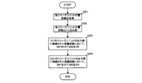
- FIG. 3 is a flowchart showing the control contents of the protection circuit 4 by the controller 30.
- the protection circuit 4 is set so that the switch SW1 is OFF and SW2 is ON, and the output voltage from the series unit 1 side is applied to the inverter 7 side as it is.
- the controller 30 acquires the voltage value (voltage value of the output terminal of the power supply circuit 2) V on the line connecting the protection circuit 4 and the inverter 7 from the voltmeter 8 (step S101). Then, the controller 30 determines whether or not the acquired voltage value V is greater than a preset threshold value V1 (step S102). When the voltage value V is larger than the preset threshold value V1 (step S102: YES), that is, when the voltage value V is increased due to an excessive inrush current, the controller 30 switches the switch SW1 in the protection circuit 4 to a value. By switching ON and SW2 to OFF, the output current from the series unit 1 side is consumed by the fixed resistor 10, and the inrush current is reduced.
- step S102 the controller 30 returns the process to step S102, and when the voltage value V becomes equal to or lower than the preset threshold value V1 (step S102: NO), that is, when the excessive inrush current is settled, the switch SW1 in the protection circuit 4 Is turned OFF and SW2 is turned ON to return to the initial state.
- the protection circuit 4 protects the load side from an excessive inrush current generated when the battery system 100 is started.
- FIG. 4 is a flowchart showing the control contents of the protection circuit 6 by the controller 30. Similar to the protection circuit 4, in the protection circuit 6 in the initial state, the switch SW1 is set to OFF and the switch SW2 is set to ON.
- the controller 30 acquires the current value I output from each series unit 1 from each ammeter 9 (step S201). Then, the controller 30 determines whether or not each acquired current value I is smaller than a preset threshold value I1 (step S202).
- the threshold value I1 is a value defined in advance as the specification of the series unit 1 as a threshold value for determining that the output current value from the series unit 1 has decreased due to the progress of deterioration, and is experimental and theoretical. Alternatively, it may be set by various simulation methods.
- the controller 30 sets the switch SW1 of the protection circuit 6 connected to the output side of the series unit 1 whose current value I is smaller than the threshold value I1 to OFF and SW2 to ON (step S203).
- the switch SW1 of the protection circuit 6 connected to the output side is set to ON and SW2 is set to OFF (step S204).
- Such switching control of the switches SW1 and SW2 by the controller 30 may be repeated by acquiring the input current value to the protection circuit 6 periodically or irregularly.
- the load resistor 8 is described as a fixed resistor.
- the variable resistor is used, and the variation in the current value is eliminated or reduced according to the current value input to each series unit 1 acquired by the controller.
- the resistance value may be variably controlled.
- a capacitor 13 is connected in parallel with the fixed resistor 10.
- the battery cell since the battery cell mainly generates electric power by a chemical reaction, it may be difficult to output sufficient electric power necessary for the electric motor 3 that is a load at the time of starting. Even in such a case, by providing the capacitor 13, the power stored in the capacitor 13 in advance when the battery system 100 is started can be used to quickly supply power in response to a request from the load side. it can.
- FIG. 6 shows another modification of the protection circuit 6.
- a third circuit 14 in which a switch SW3 and a fixed resistor 13 are connected in series is provided.
- the resistance value of the fixed resistor 13 may be set to be different from that of the fixed resistor 10 in the first circuit 11.
- the resistance value in the protection circuit 6 can be adjusted in multiple steps by switching the switches SW1 to SW3 by the controller 30, so that the variation in the current value between the series units 1 can be performed more accurately.
- the switching control of the switches SW1 to SW3 may be performed following the example described above with reference to FIG.
- FIG. 7 is a block diagram showing the overall configuration of the battery system 100 according to the second embodiment.
- parts common to the first embodiment are denoted by the same reference numerals, and detailed description thereof is omitted as appropriate.
- one of the plurality of series units 1 included in the power supply circuit 2 is the main series unit 1a, and the other slave series units 1b and 1c are used.
- the output power from the main series unit 1a is basically supplied to the required power on the load side, and when the required power is insufficient, the power is supplemented from the slave series units 1b and 1c as needed. There is a feature in the point to supply.
- a DC / DC converter is particularly employed as the protection circuit 6.
- the output voltage value of the DC / DC converter is controlled based on a control signal from the controller 30 so that the voltage value V acquired from the voltmeter 8 becomes a predetermined value V2.
- the DC / DC converter can adjust the output voltage value more flexibly based on a control signal from the controller 30.
- the present invention can be used for a battery system having a power circuit in which a plurality of series units each having a plurality of secondary battery cells connected in series are connected in parallel.
Abstract
An electric cell system (100) has a power supply circuit (2) in which n series units (1), in which battery cells are connected in series, are connected in parallel;and feeds power to the load (3) side through a first protective circuit (4) and an inverter (7) in series with respect to an output terminal of the power supply circuit (2). In particular, the present invention is characterized in being provided with (n - 1) protective circuits (6) in which the resistance can be variably controlled, the protective circuits being connected in series between positive electrodes of the n series units (1) connected in parallel.
Description
本発明は、複数の二次電池セルを直列に接続した複数のシリーズユニットが並列接続されてなる電源回路を有する電池システムの技術分野に関する。
The present invention relates to a technical field of a battery system having a power supply circuit in which a plurality of series units each having a plurality of secondary battery cells connected in series are connected in parallel.
充放電可能な二次電池として、リチウムイオン二次電池、ニッケル水素電池、鉛電池などが知られている。この種の二次電池の応用分野として、例えば電気自動車やハイブリッド電気自動車のような大電力を必要とする系に搭載される電池システムがある。特にリチウムイオン二次電池はエネルギー密度及び入出力密度が高く、且つ、サイクル寿命が長いという特徴を有するため、この分野における研究開発が盛んに行われている。
リ チ ウ ム Lithium ion secondary batteries, nickel metal hydride batteries, lead batteries and the like are known as chargeable / dischargeable secondary batteries. As an application field of this type of secondary battery, for example, there is a battery system mounted on a system that requires a large amount of power, such as an electric vehicle or a hybrid electric vehicle. In particular, lithium ion secondary batteries are characterized by high energy density, high input / output density, and long cycle life. Therefore, research and development in this field are actively conducted.
電池システムでは、複数の二次電池セルを組み合わせて電源回路を構成して運用がなされている。特に大電力を供給するために用いられる電源回路は、複数の二次電池セルを直列接続してなるシリーズユニットを並列に組み合わせて構成される場合がある。この構成は、何らかの要因によって電源回路内に短絡などの不具合が生じた場合に、電池セル間に過大電流が流れることを防ぐことができるというメリットがある。
Battery systems are operated by combining a plurality of secondary battery cells to form a power circuit. In particular, a power supply circuit used for supplying a large amount of power may be configured by combining series units formed by connecting a plurality of secondary battery cells in series. This configuration has an advantage that an excessive current can be prevented from flowing between battery cells when a problem such as a short circuit occurs in the power supply circuit due to some cause.
シリーズユニットを並列に組み合わせてなる構成では、実際の電池セルには個体差があるので、各シリーズユニットに流れる電流値には少なからずバラツキが生じる。このような電流値のバラツキは、各シリーズユニットが置かれる環境(例えば温度や湿度など)のバラツキによっても生じ得る。このように各シリーズユニットに流れる電流値にバラツキが生じると、各シリーズユニットの劣化度合いに差が生じてしまうため、問題となる。
In a configuration in which series units are combined in parallel, there are individual differences in actual battery cells, so there is a considerable variation in the current value flowing through each series unit. Such a variation in current value can also occur due to variations in the environment (for example, temperature, humidity, etc.) in which each series unit is placed. If the current value flowing through each series unit varies as described above, a difference occurs in the degree of deterioration of each series unit, which is a problem.
このような各シリーズユニットに流れる電流値のバラツキを抑制するための技術として、例えば特許文献1がある。特許文献1では、シリーズユニット毎に状態情報を検出し、該検出した状態情報に基づいて各シリーズユニットに流れる電流量を制御することにより、電流値のバラツキを抑制し、電池システムの寿命を可及的長期にする技術が開示されている。このような電流量の調整は、各シリーズユニットに直列に挿入された電力分配部により行われ、当該電力分配部は例えば可変抵抗やスイッチトキャパシタ、DC/DCコンバータ、DCチョッパなどの素子からなっている。
For example, Patent Document 1 discloses a technique for suppressing variations in the current value flowing through each series unit. In Patent Document 1, state information is detected for each series unit, and the amount of current flowing through each series unit is controlled based on the detected state information, thereby suppressing variations in current value and enabling the life of the battery system. A technique for making it as long as possible is disclosed. Such adjustment of the current amount is performed by a power distribution unit inserted in series in each series unit, and the power distribution unit includes elements such as a variable resistor, a switched capacitor, a DC / DC converter, and a DC chopper, for example. Yes.
しかしながら、上記特許文献1では電力分配部や、当該電力分配部を制御するための状態情報を検出する検出手段などをシリーズユニットと一対一で設ける必要がある。そのため、特許文献1では電池システムの回路構成が複雑化し、低コストで実現することが難しいという問題点がある。
However, in Patent Document 1, it is necessary to provide a power distribution unit and detection means for detecting state information for controlling the power distribution unit on a one-on-one basis with the series unit. Therefore, Patent Document 1 has a problem that the circuit configuration of the battery system is complicated, and it is difficult to realize the battery system at low cost.
本発明は上記問題点に鑑みなされたものであり、各シリーズユニットにおける電流値のバラツキの抑制を低コストで実現可能な電池システムを提供することを目的とする。
The present invention has been made in view of the above problems, and an object of the present invention is to provide a battery system capable of suppressing current value variation in each series unit at a low cost.
本発明の電池システムは上記課題を解決するために、複数の二次電池セルを直列に接続したn個のシリーズユニットが互いに並列に接続されてなる電源回路を有し、該電源回路の出力端子に対して直列に第1の保護回路が接続されており、該第1の保護回路の出力端子に接続されたインバータを介して負荷側に電力を供給する電池システムにおいて、前記互いに並列に接続されたn個のシリーズユニットの正極間に直列に接続され、抵抗値を可変に制御可能な(n-1)個の第2の保護回路を備えたことを特徴とする。
In order to solve the above problems, the battery system of the present invention has a power supply circuit in which n series units each having a plurality of secondary battery cells connected in series are connected in parallel to each other, and an output terminal of the power supply circuit Are connected in series with each other in a battery system that supplies power to the load side via an inverter connected to an output terminal of the first protection circuit. Further, (n-1) second protection circuits connected in series between the positive electrodes of the n series units and capable of variably controlling the resistance value are provided.
本発明によれば、(n-1)個の第2の保護回路における抵抗値を可変に制御することによって、各シリーズユニット間における電流値のバラツキを抑制することができる。即ち、特許文献1では、第2の保護回路をシリーズユニットと一対一で設ける必要があるため、第2の保護回路は合計n個必要であるが、本発明では合計(n-1)個で済む。このように、本発明では回路を構成する素子数を抑制することができるので、低コスト化と同時に、電池システムの小型化を図ることができる。
According to the present invention, it is possible to suppress variation in the current value between the series units by variably controlling the resistance value in the (n−1) second protection circuits. That is, in Patent Document 1, since it is necessary to provide the second protection circuit on a one-to-one basis with the series unit, a total of n second protection circuits are required. That's it. As described above, according to the present invention, the number of elements constituting the circuit can be reduced, so that the battery system can be downsized at the same time as the cost reduction.
前記各第2の保護回路の抵抗値は、該各第2の保護回路を流れる電流値のバラツキが減少するように制御されるとよい。例えば各第2の保護回路を流れる電流値をモニタすることにより、電流値のバラツキを測定し、該得られた電流値のバラツキを減少させるように各第2の保護抵抗の抵抗値を制御して調整するとよい。
The resistance value of each of the second protection circuits may be controlled so that variation in the current value flowing through each of the second protection circuits is reduced. For example, by monitoring the current value flowing through each second protection circuit, the variation in the current value is measured, and the resistance value of each second protection resistor is controlled so as to reduce the variation in the obtained current value. To adjust.
本発明の一態様として、前記第2の保護回路は、第1の切替手段と固定抵抗とが直列に接続されてなる第1の回路と、第2の切替手段のみからなる第2の回路とが並列に接続されてなってもよい。この態様では、固定抵抗に対応する抵抗値を有する第1の回路と、抵抗値が略ゼロである第2の回路とを切り替えることによって、より単純な回路構成で抵抗値を可変に制御することができる。
As one aspect of the present invention, the second protection circuit includes a first circuit in which a first switching unit and a fixed resistor are connected in series, and a second circuit including only the second switching unit. May be connected in parallel. In this aspect, the resistance value is variably controlled with a simpler circuit configuration by switching between the first circuit having a resistance value corresponding to the fixed resistance and the second circuit having a resistance value of substantially zero. Can do.
この場合、前記固定抵抗にコンデンサが並列に接続するとよい。電池システムを構成する電池セルは主に化学反応によって電力を生成するため、始動時に負荷側の要求に対応するだけの十分な電力を出力することが困難な場合がある。本態様では、電池システムの始動時に予めコンデンサに蓄えた電力を用いることにより、負荷側からの要求に対して迅速に電力を供給することができる。
In this case, a capacitor may be connected in parallel to the fixed resistor. Since the battery cells constituting the battery system generate electric power mainly by a chemical reaction, it may be difficult to output sufficient electric power to meet the demand on the load side at the time of starting. In this aspect, by using the power stored in the capacitor in advance at the time of starting the battery system, it is possible to supply power quickly in response to a request from the load side.
前記第2保護回路は前記(n-1)個のシリーズユニットに対して直列に接続された可変抵抗からなってもよい。この態様では、第2の回路における抵抗値の可変制御をより細かい精度で行うことができる。
The second protection circuit may comprise a variable resistor connected in series to the (n-1) series units. In this aspect, the variable control of the resistance value in the second circuit can be performed with finer accuracy.
本発明の他の態様では、前記n個のシリーズユニットは少なくとも一つのマスタユニットと、その他のスレーブユニットとからなり、前記スレーブユニットにおける第2の保護回路は、前記マスタユニットの出力電圧が所定値になるように抵抗値が可変に制御してもよい。この場合は特に、前記スレーブユニットにおける第2の保護回路は、該スレーブユニットに対して直列に接続されたDC/DCコンバータ又はチョッパ回路からなるとよい。
In another aspect of the present invention, the n series units include at least one master unit and other slave units, and the second protection circuit in the slave unit has an output voltage of the master unit of a predetermined value. The resistance value may be variably controlled so that In this case, in particular, the second protection circuit in the slave unit may include a DC / DC converter or a chopper circuit connected in series to the slave unit.
本発明によれば、(n-1)個の第2の保護回路における抵抗値を可変に制御することによって、各シリーズユニット間における電流値のバラツキを抑制することができる。即ち、特許文献1では、第2の保護回路をシリーズユニットと一対一で設ける必要があるため、第2の保護回路は合計n個必要であるが、本発明では合計(n-1)個で済む。このように、本発明では回路を構成する素子数を抑制することができるので、低コスト化と同時に、電池システムの小型化を図ることができる。
According to the present invention, it is possible to suppress variation in the current value between the series units by variably controlling the resistance value in the (n−1) second protection circuits. That is, in Patent Document 1, since it is necessary to provide the second protection circuit on a one-to-one basis with the series unit, a total of n second protection circuits are required. That's it. As described above, according to the present invention, the number of elements constituting the circuit can be reduced, so that the battery system can be downsized at the same time as the cost reduction.
以下、図面を参照して本発明の好適な実施形態を例示的に詳しく説明する。但しこの実施形態に記載されている構成部品の寸法、材質、形状、その相対的配置等は特に特定的な記載がない限りは、この発明の範囲をそれに限定する趣旨ではなく、単なる説明例に過ぎない。
Hereinafter, exemplary embodiments of the present invention will be described in detail with reference to the drawings. However, the dimensions, materials, shapes, relative arrangements, and the like of the components described in this embodiment are not intended to limit the scope of the present invention unless otherwise specified, but are merely illustrative examples. Not too much.
(第1実施例)
図1は第1実施例に係る電池システム100の全体構成を示すブロック図である。電地システム100は、複数の二次電池セルが直列に接続されてなるシリーズユニット1を複数備えてなる電源回路2を有しており、該電源回路2の出力端子2aには、第1の保護回路4(以下、「保護回路4」と称する)及びインバータ7を介して三相誘導電動機である電動モータ3が接続されている。電源回路2から出力された直流電力は、インバータ7によって電動モータ3の駆動に適した周波数、電圧値を有する交流電力に変換されて、負荷である電動モータ3に供給される。 (First embodiment)
FIG. 1 is a block diagram showing the overall configuration of thebattery system 100 according to the first embodiment. The electrical system 100 includes a power supply circuit 2 including a plurality of series units 1 in which a plurality of secondary battery cells are connected in series. The output terminal 2 a of the power supply circuit 2 includes a first power supply circuit 2. An electric motor 3, which is a three-phase induction motor, is connected via a protection circuit 4 (hereinafter referred to as “protection circuit 4”) and an inverter 7. The DC power output from the power supply circuit 2 is converted into AC power having a frequency and voltage value suitable for driving the electric motor 3 by the inverter 7 and supplied to the electric motor 3 as a load.
図1は第1実施例に係る電池システム100の全体構成を示すブロック図である。電地システム100は、複数の二次電池セルが直列に接続されてなるシリーズユニット1を複数備えてなる電源回路2を有しており、該電源回路2の出力端子2aには、第1の保護回路4(以下、「保護回路4」と称する)及びインバータ7を介して三相誘導電動機である電動モータ3が接続されている。電源回路2から出力された直流電力は、インバータ7によって電動モータ3の駆動に適した周波数、電圧値を有する交流電力に変換されて、負荷である電動モータ3に供給される。 (First embodiment)
FIG. 1 is a block diagram showing the overall configuration of the
インバータ7は三相誘導電動機である電動モータ3を駆動対象としており、駆動周波数が低く、大電流大電力であるモータ制御系のインバータ回路である。典型的には、スイッチング素子6個を用いた三相出力インバータであり、電動モータ3の回転速度調整や出力トルクの調整が容易化し、効率を大幅に改善する機能を有している。電源モータ3は、このようにインバータ7を介して供給される交流電力によって駆動され、その出力軸に連結された動力伝達機構を介して駆動輪に連結され、車両の走行が行われる。
The inverter 7 is an inverter circuit of a motor control system that drives the electric motor 3 that is a three-phase induction motor and has a low driving frequency and a large current and a large power. Typically, it is a three-phase output inverter using six switching elements, and has a function of facilitating adjustment of the rotational speed and output torque of the electric motor 3 and greatly improving efficiency. The power supply motor 3 is driven by the AC power supplied through the inverter 7 as described above, and is connected to driving wheels through a power transmission mechanism connected to the output shaft thereof, so that the vehicle travels.
ここで、インバータ7には平滑用のコンデンサ等が含まれており、電池システム100の起動時に一時的に過大な突入電流が発生するおそれがある。保護回路4は、このような突入電流から電動モータ3側を保護するために設けられたものであり、その具体的な回路構成については後述することとする。
Here, the inverter 7 includes a smoothing capacitor or the like, and an excessive inrush current may be temporarily generated when the battery system 100 is started. The protection circuit 4 is provided to protect the electric motor 3 side from such an inrush current, and a specific circuit configuration thereof will be described later.
尚、インバータ7に代えて、同じく平滑用のコンデンサ等が含まれるDC/DCコンバータ等のパワーエレクトロ部品を用いられた場合にも、このような保護回路4が用いられる。
It should be noted that such a protection circuit 4 is also used when a power electronic component such as a DC / DC converter including a smoothing capacitor or the like is used instead of the inverter 7.
保護回路4とインバータ7とを接続するライン上には電圧計8が設けられており、インバータ7への入力電圧値がモニタ可能に構成されている。電圧計8によってモニタされた電圧値は、電池システム100の全体の制御を司るコントローラ30に送信され、後述する制御の実施に利用される。
A voltmeter 8 is provided on a line connecting the protection circuit 4 and the inverter 7 so that the input voltage value to the inverter 7 can be monitored. The voltage value monitored by the voltmeter 8 is transmitted to the controller 30 that governs overall control of the battery system 100, and is used to implement control described later.
続いて電源回路2の詳細な構成について説明すると、電源回路2は複数のシリーズユニット1が互いに並列に接続されてなり、各シリーズユニット1の正極間を接続する配線上には第2の保護回路6(以下、「保護回路6」と称する)が直列に接続されて構成されている。ここで、シリーズユニット1に含まれる二次電池セルは、例えばリチウムイオン二次電池セルであるが、ニッケル水素電池、鉛電池など各種二次電池セルを用いてもよい。
Next, the detailed configuration of the power supply circuit 2 will be described. The power supply circuit 2 includes a plurality of series units 1 connected in parallel to each other, and a second protection circuit is provided on the wiring connecting the positive electrodes of the series units 1. 6 (hereinafter referred to as “protection circuit 6”) are connected in series. Here, the secondary battery cell included in the series unit 1 is, for example, a lithium ion secondary battery cell, but various secondary battery cells such as a nickel metal hydride battery and a lead battery may be used.
また、各シリーズユニット1の正極側には電流計9が直列に接続されており、各シリーズユニット1から出力される電流値がモニタ可能に構成されている。電流計9によってモニタされた電流値は、電池システム100の全体の制御をつかさどるコントローラ30に送信され、後述する制御の実施に利用される。
Also, an ammeter 9 is connected in series to the positive electrode side of each series unit 1 so that the current value output from each series unit 1 can be monitored. The current value monitored by the ammeter 9 is transmitted to the controller 30 that controls the entire battery system 100, and is used to implement the control described later.
ここで、電源回路2には合計n個(nは2以上の整数)のシリーズユニット1が含まれており、本実施例では特にn=3である。そして、合計n個のシリーズユニット1に対して、(n-1)個の保護回路6が設けられている。つまり、本実施例では3個のシリーズユニット1に対して、保護回路6は2個設けられている。
Here, the power supply circuit 2 includes a total of n (n is an integer of 2 or more) series units 1, and in this embodiment, n = 3 in particular. Further, (n−1) protection circuits 6 are provided for a total of n series units 1. That is, in this embodiment, two protection circuits 6 are provided for the three series units 1.
ここで、互いに並列接続された各シリーズユニット1は同様の構成を有しており、同一の負荷(電動モータ3)に接続されているため、理想的には各シリーズユニット1から出力される電流値は等しくなる。しかしながら、実際には、各シリーズユニット1に含まれる二次電池セル間の個体差や、各シリーズユニット1の動作温度差に起因して出力される電流値にバラツキが生じてしまう。すると出力される電流値が大きいシリーズユニット1では電池セルの劣化が進行し、出力電圧が低下してしまう。その結果、その他の並列に接続されたシリーズユニット1との間の電位差に起因して、シリーズユニット1間で電流が流れてしまい、電池システム100が危険な状態に陥ってしまうおそれがある。
Here, since each series unit 1 connected in parallel has the same configuration and is connected to the same load (electric motor 3), the current output from each series unit 1 is ideal. The values are equal. However, in reality, the output current value varies due to the individual difference between the secondary battery cells included in each series unit 1 and the operating temperature difference of each series unit 1. Then, in the series unit 1 with a large current value to be output, the deterioration of the battery cell proceeds, and the output voltage decreases. As a result, current flows between the series units 1 due to a potential difference with the other series units 1 connected in parallel, and the battery system 100 may be in a dangerous state.
上記特許文献1では、このような電源回路2から出力される電流値のバラツキを抑制するために、n個のシリーズユニットに対して一対一に保護回路6を設ける必要があった。つまり、従来技術では、3個のシリーズユニット1が有る場合には、3個の保護回路6を設ける必要があった。それに対し、本発明では3個のシリーズユニット1に対して、保護回路6が2個で済む。そのため、回路化構成を簡素化することができ、低コスト化や小型化により適応した電池システムを実現することができる。
In Patent Document 1, in order to suppress such a variation in the current value output from the power supply circuit 2, it is necessary to provide the protection circuits 6 on a one-to-one basis for n series units. That is, in the prior art, when there are three series units 1, it is necessary to provide three protection circuits 6. On the other hand, in the present invention, two protection circuits 6 are sufficient for the three series units 1. Therefore, the circuitized configuration can be simplified, and a battery system adapted for cost reduction and downsizing can be realized.
次に図2を参照して保護回路6の具体的な回路構成について説明する。図2は、第1実施例に係る電池システム100が備える保護回路6の構成を示す回路図である。尚、本実施例では特に保護回路4も、回路構成の簡略化のために保護回路6と同様の構成を有するものとして、以下説明する。
Next, a specific circuit configuration of the protection circuit 6 will be described with reference to FIG. FIG. 2 is a circuit diagram illustrating a configuration of the protection circuit 6 included in the battery system 100 according to the first embodiment. In the present embodiment, the protection circuit 4 will be described below assuming that the protection circuit 4 has the same configuration as the protection circuit 6 in order to simplify the circuit configuration.
保護回路6は、スイッチSW1と負荷抵抗10とが直列に接続されてなる第1の回路11と、スイッチSW2のみからなる第2の回路12とが並列に接続された構成を有する。スイッチSW1及びSW2はコントローラ30からの制御信号に基づいて、そのON/OFFが切替可能に構成されている。このようにスイッチSW1及びSW2を切り替え制御することによって、各保護回路6における抵抗値をゼロと所定の抵抗値との間を可変に切り替え制御可能に構成されている。
The protection circuit 6 has a configuration in which a first circuit 11 in which a switch SW1 and a load resistor 10 are connected in series and a second circuit 12 made up of only the switch SW2 are connected in parallel. The switches SW1 and SW2 are configured to be switchable on / off based on a control signal from the controller 30. Thus, by controlling the switches SW1 and SW2, the resistance value in each protection circuit 6 can be variably switched between zero and a predetermined resistance value.
本実施例では特に、負荷抵抗10は所定の抵抗値を有する固定抵抗素子である。この所定の抵抗値は、シリーズユニット1間の出力電流値にバラツキが生じた場合に、電流値が大きいラインにおいて付加抵抗10によって電力を消費し、電流値を低減させるように設定させることにより、バラツキを抑制する。
Particularly in this embodiment, the load resistor 10 is a fixed resistance element having a predetermined resistance value. The predetermined resistance value is set such that when the output current value between the series units 1 varies, power is consumed by the additional resistor 10 in a line having a large current value, and the current value is reduced. Suppresses variation.
尚、本実施例では負荷抵抗10として固定抵抗を用いたが、これに代えて、可変抵抗やDC/DCコンバータ等を用いてもよい。この場合、抵抗値が可変に調整することができるので、より精度良くシリーズユニット1間における電流値のバラツキを抑制することが可能となる。
In this embodiment, a fixed resistor is used as the load resistor 10, but a variable resistor, a DC / DC converter, or the like may be used instead. In this case, since the resistance value can be variably adjusted, it is possible to suppress the variation in the current value between the series units 1 with higher accuracy.
ここで図3を参照して、コントローラ30による保護回路4の制御内容について具体的に説明する。図3はコントローラ30による保護回路4の制御内容を示すフローチャート図である。尚、初期状態に置いて保護回路4はスイッチSW1がOFF、SW2がONに設定されており、シリーズユニット1側からの出力電圧がそのままインバータ7側に印加されるようになっている。
Here, with reference to FIG. 3, the control content of the protection circuit 4 by the controller 30 will be specifically described. FIG. 3 is a flowchart showing the control contents of the protection circuit 4 by the controller 30. In the initial state, the protection circuit 4 is set so that the switch SW1 is OFF and SW2 is ON, and the output voltage from the series unit 1 side is applied to the inverter 7 side as it is.
まずコントローラ30は電圧計8から保護回路4とインバータ7とを接続するライン上の電圧値(電源回路2の出力端子の電圧値)Vを取得する(ステップS101)。そして、コントローラ30は、当該取得した電圧値Vが予め設定された閾値V1より大きいか否かを判定する(ステップS102)。電圧値Vが予め設定された閾値V1より大きい場合(ステップS102:YES)、即ち、過大な突入電流が生じることによって電圧値Vが大きくなっている場合、コントローラ30は保護回路4におけるスイッチSW1をON、SW2をOFFに切り替えることによって、シリーズユニット1側からの出力電流を固定抵抗10によって消費し、突入電流の軽減を図る。そしてコントローラ30は処理をステップS102に戻し、電圧値Vが予め設定された閾値V1以下になった場合(ステップS102:NO)、即ち、過大な突入電流が収まった場合、保護回路4におけるスイッチSW1をOFF、SW2をONに切り替えて、初期状態に戻す。
First, the controller 30 acquires the voltage value (voltage value of the output terminal of the power supply circuit 2) V on the line connecting the protection circuit 4 and the inverter 7 from the voltmeter 8 (step S101). Then, the controller 30 determines whether or not the acquired voltage value V is greater than a preset threshold value V1 (step S102). When the voltage value V is larger than the preset threshold value V1 (step S102: YES), that is, when the voltage value V is increased due to an excessive inrush current, the controller 30 switches the switch SW1 in the protection circuit 4 to a value. By switching ON and SW2 to OFF, the output current from the series unit 1 side is consumed by the fixed resistor 10, and the inrush current is reduced. Then, the controller 30 returns the process to step S102, and when the voltage value V becomes equal to or lower than the preset threshold value V1 (step S102: NO), that is, when the excessive inrush current is settled, the switch SW1 in the protection circuit 4 Is turned OFF and SW2 is turned ON to return to the initial state.
このような制御によって保護回路4では、電池システム100の始動時に発生する過大な突入電流から負荷側の保護が実施される。
With such control, the protection circuit 4 protects the load side from an excessive inrush current generated when the battery system 100 is started.
続いて図4を参照して、コントローラ30による保護回路6の制御内容について具体的に説明する。図4はコントローラ30による保護回路6の制御内容を示すフローチャート図である。尚、保護回路4と同様に、初期状態において保護回路6では、スイッチSW1はOFFに設定されており、スイッチSW2はONに設定されている。
Subsequently, with reference to FIG. 4, the control content of the protection circuit 6 by the controller 30 will be specifically described. FIG. 4 is a flowchart showing the control contents of the protection circuit 6 by the controller 30. Similar to the protection circuit 4, in the protection circuit 6 in the initial state, the switch SW1 is set to OFF and the switch SW2 is set to ON.
まずコントローラ30は各電流計9から各シリーズユニット1から出力される電流値Iを取得する(ステップS201)。そして、コントローラ30は、当該取得した各電流値Iについて、予め設定された閾値I1より小さいか否かを判定する(ステップS202)。ここで閾値I1は、劣化が進行することによってシリーズユニット1からの出力電流値が低下したと判定するための閾値として、予めシリーズユニット1のスペックとして規定される値であり、実験的、理論的又はシミュレーション的な各種手法により設定するとよい。
First, the controller 30 acquires the current value I output from each series unit 1 from each ammeter 9 (step S201). Then, the controller 30 determines whether or not each acquired current value I is smaller than a preset threshold value I1 (step S202). Here, the threshold value I1 is a value defined in advance as the specification of the series unit 1 as a threshold value for determining that the output current value from the series unit 1 has decreased due to the progress of deterioration, and is experimental and theoretical. Alternatively, it may be set by various simulation methods.
そしてコントローラ30は、電流値Iが閾値I1より小さいシリーズユニット1については、その出力側に接続された保護回路6のスイッチSW1をOFF、SW2をONに設定する(ステップS203)。一方、電流値Iが閾値I1以上であるシリーズユニット1については、その出力側に接続された保護回路6のスイッチSW1をON、SW2をOFFに設定する(ステップS204)。その結果、出力される電流値Iが大きいシリーズユニット1では固定抵抗10によって電流値が抑制されるので、電流値Iが小さいシリーズユニット1との間のバラツキを低減することができる。
Then, the controller 30 sets the switch SW1 of the protection circuit 6 connected to the output side of the series unit 1 whose current value I is smaller than the threshold value I1 to OFF and SW2 to ON (step S203). On the other hand, for the series unit 1 whose current value I is equal to or greater than the threshold value I1, the switch SW1 of the protection circuit 6 connected to the output side is set to ON and SW2 is set to OFF (step S204). As a result, since the current value is suppressed by the fixed resistor 10 in the series unit 1 having a large current value I to be output, variation with the series unit 1 having a small current value I can be reduced.
このようなコントローラ30によるスイッチSW1及びSW2の切替制御は、定期的又は不定期的に保護回路6への入力電流値を取得することにより、繰り返し行うとよい。
Such switching control of the switches SW1 and SW2 by the controller 30 may be repeated by acquiring the input current value to the protection circuit 6 periodically or irregularly.
尚、本実施例では負荷抵抗8を固定抵抗であるとして説明したが、可変抵抗を用い、コントローラが取得した各シリーズユニット1に入力される電流値に応じて、電流値のバラツキが解消又は軽減されるように抵抗値を可変に制御してもよい。
In the present embodiment, the load resistor 8 is described as a fixed resistor. However, the variable resistor is used, and the variation in the current value is eliminated or reduced according to the current value input to each series unit 1 acquired by the controller. As described above, the resistance value may be variably controlled.
ここで、保護回路6の変形例について図5を参照して説明する。図5の例では、固定抵抗10に対して並列にコンデンサ13が接続されている。電池システム100では、電池セルは主に化学反応によって電力を生成するため、始動時に負荷である電動モータ3に必要な十分な電力を出力することが困難な場合がある。このような場合であっても、コンデンサ13を設けることによって、電池システム100の始動時に予めコンデンサ13に蓄えた電力を用いることにより、負荷側からの要求に対して迅速に電力を供給することができる。
Here, a modified example of the protection circuit 6 will be described with reference to FIG. In the example of FIG. 5, a capacitor 13 is connected in parallel with the fixed resistor 10. In the battery system 100, since the battery cell mainly generates electric power by a chemical reaction, it may be difficult to output sufficient electric power necessary for the electric motor 3 that is a load at the time of starting. Even in such a case, by providing the capacitor 13, the power stored in the capacitor 13 in advance when the battery system 100 is started can be used to quickly supply power in response to a request from the load side. it can.
また図6に保護回路6の他の変形例を示す。図6の例では、上述の第1の回路11と第2の回路12とに加えて、スイッチSW3と固定抵抗13とが直列に接続されてなる第3の回路14を備える。特に固定抵抗13の抵抗値を、第1の回路11における固定抵抗10とは異なるように設定するとよい。これにより、コントローラ30によってスイッチSW1乃至SW3を切り替え制御することで保護回路6における抵抗値を多段階的に調整できるので、各シリーズユニット1間における電流値のバラツキを、より精度よく行うことができる。尚、スイッチSW1乃至SW3の切替制御は、図4を参照して上述した例に倣って行えばよい。
FIG. 6 shows another modification of the protection circuit 6. In the example of FIG. 6, in addition to the first circuit 11 and the second circuit 12 described above, a third circuit 14 in which a switch SW3 and a fixed resistor 13 are connected in series is provided. In particular, the resistance value of the fixed resistor 13 may be set to be different from that of the fixed resistor 10 in the first circuit 11. As a result, the resistance value in the protection circuit 6 can be adjusted in multiple steps by switching the switches SW1 to SW3 by the controller 30, so that the variation in the current value between the series units 1 can be performed more accurately. . Note that the switching control of the switches SW1 to SW3 may be performed following the example described above with reference to FIG.
(第2実施例)
次に図7を参照して第2実施例に係る電池システム100について説明する。図7は第2実施例に係る電池システム100の全体構成を示すブロック図である。尚、図7において第1実施例と共通する部分には共通の符号を付すこととし、適宜詳細な説明は省略することとする。 (Second embodiment)
Next, thebattery system 100 according to the second embodiment will be described with reference to FIG. FIG. 7 is a block diagram showing the overall configuration of the battery system 100 according to the second embodiment. In FIG. 7, parts common to the first embodiment are denoted by the same reference numerals, and detailed description thereof is omitted as appropriate.
次に図7を参照して第2実施例に係る電池システム100について説明する。図7は第2実施例に係る電池システム100の全体構成を示すブロック図である。尚、図7において第1実施例と共通する部分には共通の符号を付すこととし、適宜詳細な説明は省略することとする。 (Second embodiment)
Next, the
第2実施例では電源回路2に含まれる複数のシリーズユニット1のうち一つをメインシリーズユニット1aとし、その他のスレーブシリーズユニット1b及び1cとしている。この電源回路2では負荷側の要求電力に対し、基本的にはメインシリーズユニット1aからの出力電力を供給し、それが要求電力に足りない場合に適宜スレーブシリーズユニット1b及び1cから電力を補助的に供給する点に特徴がある。
In the second embodiment, one of the plurality of series units 1 included in the power supply circuit 2 is the main series unit 1a, and the other slave series units 1b and 1c are used. In this power supply circuit 2, the output power from the main series unit 1a is basically supplied to the required power on the load side, and when the required power is insufficient, the power is supplemented from the slave series units 1b and 1c as needed. There is a feature in the point to supply.
また本実施例では、保護回路6として特にDC/DCコンバータを採用している。DC/DCコンバータの出力電圧値は、コントローラ30からの制御信号に基づいて、電圧計8から取得した電圧値Vが所定値V2になるように制御される。DC/DCコンバータは固定抵抗などとは異なり、コントローラ30からの制御信号に基づいて出力電圧値をより柔軟に調整可能である。
In this embodiment, a DC / DC converter is particularly employed as the protection circuit 6. The output voltage value of the DC / DC converter is controlled based on a control signal from the controller 30 so that the voltage value V acquired from the voltmeter 8 becomes a predetermined value V2. Unlike a fixed resistor or the like, the DC / DC converter can adjust the output voltage value more flexibly based on a control signal from the controller 30.
本発明は、複数の二次電池セルを直列に接続した複数のシリーズユニットが並列接続されてなる電源回路を有する電池システムに利用可能である。
The present invention can be used for a battery system having a power circuit in which a plurality of series units each having a plurality of secondary battery cells connected in series are connected in parallel.
Claims (6)
- 複数の二次電池セルを直列に接続したn個のシリーズユニットが互いに並列に接続されてなる電源回路を有し、該電源回路の出力端子に対して直列に第1の保護回路が接続されており、該第1の保護回路の出力端子に接続されたインバータを介して負荷側に電力を供給する電池システムにおいて、
前記互いに並列に接続されたn個のシリーズユニットの正極間に直列に接続され、抵抗値を可変に制御可能な(n-1)個の第2の保護回路を備えたことを特徴とする電池システム。 A power circuit in which n series units each having a plurality of secondary battery cells connected in series are connected in parallel to each other, and a first protection circuit is connected in series to the output terminal of the power circuit; In the battery system for supplying power to the load side via an inverter connected to the output terminal of the first protection circuit,
A battery comprising (n-1) second protection circuits connected in series between the positive electrodes of the n series units connected in parallel to each other, the resistance value of which can be variably controlled. system. - 前記各第2の保護回路の抵抗値は、該各第2の保護回路を流れる電流値のバラツキが減少するように制御されることを特徴とする請求項1に記載の電池システム。 2. The battery system according to claim 1, wherein the resistance value of each second protection circuit is controlled so as to reduce variation in a current value flowing through each second protection circuit.
- 前記第2の保護回路は、第1の切替手段と固定抵抗とが直列に接続されてなる第1の回路と、第2の切替手段のみからなる第2の回路とが並列に接続されてなることを特徴とする請求項1又は2に記載の電池システム。 The second protection circuit is formed by connecting in parallel a first circuit in which a first switching unit and a fixed resistor are connected in series, and a second circuit including only the second switching unit. The battery system according to claim 1 or 2, wherein
- 前記固定抵抗にコンデンサが並列に接続されたことを特徴とする請求項3に記載の電池システム。 4. The battery system according to claim 3, wherein a capacitor is connected in parallel to the fixed resistor.
- 前記n個のシリーズユニットは少なくとも一つのマスタユニットと、その他のスレーブユニットとからなり、
前記スレーブユニットにおける第2の保護回路は、前記マスタユニットの出力電圧が所定値になるように抵抗値が可変に制御されることを特徴とする請求項1又は2に記載の電池システム。 The n series units include at least one master unit and other slave units,
3. The battery system according to claim 1, wherein a resistance value of the second protection circuit in the slave unit is variably controlled so that an output voltage of the master unit becomes a predetermined value. - 前記スレーブユニットにおける第2の保護回路は、該スレーブユニットに対して直列に接続されたDC/DCコンバータ又はチョッパ回路からなることを特徴とする請求項5に記載の電池システム。 6. The battery system according to claim 5, wherein the second protection circuit in the slave unit includes a DC / DC converter or a chopper circuit connected in series to the slave unit.
Applications Claiming Priority (2)
| Application Number | Priority Date | Filing Date | Title |
|---|---|---|---|
| JP2011028339A JP5517965B2 (en) | 2011-02-14 | 2011-02-14 | Battery system |
| JP2011-028339 | 2011-02-14 |
Publications (1)
| Publication Number | Publication Date |
|---|---|
| WO2012111410A1 true WO2012111410A1 (en) | 2012-08-23 |
Family
ID=46672347
Family Applications (1)
| Application Number | Title | Priority Date | Filing Date |
|---|---|---|---|
| PCT/JP2012/051894 WO2012111410A1 (en) | 2011-02-14 | 2012-01-27 | Electric cell system |
Country Status (2)
| Country | Link |
|---|---|
| JP (1) | JP5517965B2 (en) |
| WO (1) | WO2012111410A1 (en) |
Cited By (3)
| Publication number | Priority date | Publication date | Assignee | Title |
|---|---|---|---|---|
| CN104682705A (en) * | 2015-02-13 | 2015-06-03 | 华为技术有限公司 | Direct current-direct current bidirectional conversion circuit and power supply |
| EP3270455A1 (en) * | 2016-07-14 | 2018-01-17 | GE Energy Power Conversion Technology Limited | Battery storage system with integrated inverter |
| US10777863B2 (en) | 2016-07-14 | 2020-09-15 | Ge Energy Power Conversion Technology Ltd | Battery storage system with integrated inverter |
Citations (4)
| Publication number | Priority date | Publication date | Assignee | Title |
|---|---|---|---|---|
| JP2003189496A (en) * | 2001-12-12 | 2003-07-04 | Mitsubishi Heavy Ind Ltd | Power storage system and its charge/discharge controlling method |
| JP2008118790A (en) * | 2006-11-06 | 2008-05-22 | Hitachi Ltd | Power controller |
| WO2010018644A1 (en) * | 2008-08-13 | 2010-02-18 | 三菱重工業株式会社 | Electricity storage system |
| WO2010067735A1 (en) * | 2008-12-09 | 2010-06-17 | 三菱重工業株式会社 | Voltage equalization device, method, program, and power accumulation system |
-
2011
- 2011-02-14 JP JP2011028339A patent/JP5517965B2/en not_active Expired - Fee Related
-
2012
- 2012-01-27 WO PCT/JP2012/051894 patent/WO2012111410A1/en active Application Filing
Patent Citations (4)
| Publication number | Priority date | Publication date | Assignee | Title |
|---|---|---|---|---|
| JP2003189496A (en) * | 2001-12-12 | 2003-07-04 | Mitsubishi Heavy Ind Ltd | Power storage system and its charge/discharge controlling method |
| JP2008118790A (en) * | 2006-11-06 | 2008-05-22 | Hitachi Ltd | Power controller |
| WO2010018644A1 (en) * | 2008-08-13 | 2010-02-18 | 三菱重工業株式会社 | Electricity storage system |
| WO2010067735A1 (en) * | 2008-12-09 | 2010-06-17 | 三菱重工業株式会社 | Voltage equalization device, method, program, and power accumulation system |
Cited By (4)
| Publication number | Priority date | Publication date | Assignee | Title |
|---|---|---|---|---|
| CN104682705A (en) * | 2015-02-13 | 2015-06-03 | 华为技术有限公司 | Direct current-direct current bidirectional conversion circuit and power supply |
| CN104682705B (en) * | 2015-02-13 | 2017-06-20 | 华为技术有限公司 | A kind of DC two-way changing circuit and power supply |
| EP3270455A1 (en) * | 2016-07-14 | 2018-01-17 | GE Energy Power Conversion Technology Limited | Battery storage system with integrated inverter |
| US10777863B2 (en) | 2016-07-14 | 2020-09-15 | Ge Energy Power Conversion Technology Ltd | Battery storage system with integrated inverter |
Also Published As
| Publication number | Publication date |
|---|---|
| JP5517965B2 (en) | 2014-06-11 |
| JP2012170209A (en) | 2012-09-06 |
Similar Documents
| Publication | Publication Date | Title |
|---|---|---|
| CN110281810B (en) | DC charging of smart batteries | |
| US9160191B2 (en) | Battery pack and method for minimizing cell voltage deviations | |
| WO2017130614A1 (en) | Battery control device | |
| EP2717415A1 (en) | Electricity storage system | |
| WO2013118271A1 (en) | Parallel accumulator system and method of control thereof | |
| KR20140097286A (en) | Device for balancing the charge of the elements of an electrical power battery | |
| JP2005151720A (en) | Cell balance correcting device, secondary battery, method of correcting cell balance and cell balance correcting program | |
| JP2009286292A (en) | Vehicular power supply device | |
| JP2018110525A (en) | Charge balancing of battery | |
| JP2016523503A (en) | Method for controlling an energy storage system | |
| WO2012147121A1 (en) | Cell pack | |
| WO2013140709A1 (en) | Balance correction device and power storage system | |
| CN101789609A (en) | Battery equalization system, method and circuit | |
| JP6348219B2 (en) | Power control system and method for adjusting the input power limit of a DC-DC voltage converter | |
| JP5517965B2 (en) | Battery system | |
| US10618419B2 (en) | Energy storage arrangement comprising multiple energy stores | |
| CN107005077B (en) | Power control device and power control system | |
| JP2011130534A (en) | Power supply device for vehicle | |
| JP5423955B2 (en) | Electric vehicle battery module | |
| JP2017112734A (en) | Battery control system | |
| JP2012249450A (en) | Charger | |
| JP2010206933A (en) | Power feed device | |
| JP5385728B2 (en) | Control method and control apparatus | |
| WO2012063300A1 (en) | Fuel cell output control device | |
| KR102336964B1 (en) | Battery for hybrid vehicle and control method thereof |
Legal Events
| Date | Code | Title | Description |
|---|---|---|---|
| 121 | Ep: the epo has been informed by wipo that ep was designated in this application |
Ref document number: 12747548 Country of ref document: EP Kind code of ref document: A1 |
|
| NENP | Non-entry into the national phase |
Ref country code: DE |
|
| 122 | Ep: pct application non-entry in european phase |
Ref document number: 12747548 Country of ref document: EP Kind code of ref document: A1 |