WO2012111084A1 - ハイブリッド車両の駆動制御装置 - Google Patents
ハイブリッド車両の駆動制御装置 Download PDFInfo
- Publication number
- WO2012111084A1 WO2012111084A1 PCT/JP2011/053100 JP2011053100W WO2012111084A1 WO 2012111084 A1 WO2012111084 A1 WO 2012111084A1 JP 2011053100 W JP2011053100 W JP 2011053100W WO 2012111084 A1 WO2012111084 A1 WO 2012111084A1
- Authority
- WO
- WIPO (PCT)
- Prior art keywords
- target
- power
- motor generator
- engine
- drive
- Prior art date
- Legal status (The legal status is an assumption and is not a legal conclusion. Google has not performed a legal analysis and makes no representation as to the accuracy of the status listed.)
- Ceased
Links
Images







Classifications
-
- B—PERFORMING OPERATIONS; TRANSPORTING
- B60—VEHICLES IN GENERAL
- B60K—ARRANGEMENT OR MOUNTING OF PROPULSION UNITS OR OF TRANSMISSIONS IN VEHICLES; ARRANGEMENT OR MOUNTING OF PLURAL DIVERSE PRIME-MOVERS IN VEHICLES; AUXILIARY DRIVES FOR VEHICLES; INSTRUMENTATION OR DASHBOARDS FOR VEHICLES; ARRANGEMENTS IN CONNECTION WITH COOLING, AIR INTAKE, GAS EXHAUST OR FUEL SUPPLY OF PROPULSION UNITS IN VEHICLES
- B60K6/00—Arrangement or mounting of plural diverse prime-movers for mutual or common propulsion, e.g. hybrid propulsion systems comprising electric motors and internal combustion engines
- B60K6/20—Arrangement or mounting of plural diverse prime-movers for mutual or common propulsion, e.g. hybrid propulsion systems comprising electric motors and internal combustion engines the prime-movers consisting of electric motors and internal combustion engines, e.g. HEVs
- B60K6/42—Arrangement or mounting of plural diverse prime-movers for mutual or common propulsion, e.g. hybrid propulsion systems comprising electric motors and internal combustion engines the prime-movers consisting of electric motors and internal combustion engines, e.g. HEVs characterised by the architecture of the hybrid electric vehicle
- B60K6/44—Series-parallel type
- B60K6/445—Differential gearing distribution type
-
- B—PERFORMING OPERATIONS; TRANSPORTING
- B60—VEHICLES IN GENERAL
- B60W—CONJOINT CONTROL OF VEHICLE SUB-UNITS OF DIFFERENT TYPE OR DIFFERENT FUNCTION; CONTROL SYSTEMS SPECIALLY ADAPTED FOR HYBRID VEHICLES; ROAD VEHICLE DRIVE CONTROL SYSTEMS FOR PURPOSES NOT RELATED TO THE CONTROL OF A PARTICULAR SUB-UNIT
- B60W20/00—Control systems specially adapted for hybrid vehicles
- B60W20/10—Controlling the power contribution of each of the prime movers to meet required power demand
- B60W20/13—Controlling the power contribution of each of the prime movers to meet required power demand in order to stay within battery power input or output limits; in order to prevent overcharging or battery depletion
-
- B—PERFORMING OPERATIONS; TRANSPORTING
- B60—VEHICLES IN GENERAL
- B60W—CONJOINT CONTROL OF VEHICLE SUB-UNITS OF DIFFERENT TYPE OR DIFFERENT FUNCTION; CONTROL SYSTEMS SPECIALLY ADAPTED FOR HYBRID VEHICLES; ROAD VEHICLE DRIVE CONTROL SYSTEMS FOR PURPOSES NOT RELATED TO THE CONTROL OF A PARTICULAR SUB-UNIT
- B60W10/00—Conjoint control of vehicle sub-units of different type or different function
- B60W10/04—Conjoint control of vehicle sub-units of different type or different function including control of propulsion units
- B60W10/06—Conjoint control of vehicle sub-units of different type or different function including control of propulsion units including control of combustion engines
-
- B—PERFORMING OPERATIONS; TRANSPORTING
- B60—VEHICLES IN GENERAL
- B60W—CONJOINT CONTROL OF VEHICLE SUB-UNITS OF DIFFERENT TYPE OR DIFFERENT FUNCTION; CONTROL SYSTEMS SPECIALLY ADAPTED FOR HYBRID VEHICLES; ROAD VEHICLE DRIVE CONTROL SYSTEMS FOR PURPOSES NOT RELATED TO THE CONTROL OF A PARTICULAR SUB-UNIT
- B60W10/00—Conjoint control of vehicle sub-units of different type or different function
- B60W10/04—Conjoint control of vehicle sub-units of different type or different function including control of propulsion units
- B60W10/08—Conjoint control of vehicle sub-units of different type or different function including control of propulsion units including control of electric propulsion units, e.g. motors or generators
-
- B—PERFORMING OPERATIONS; TRANSPORTING
- B60—VEHICLES IN GENERAL
- B60W—CONJOINT CONTROL OF VEHICLE SUB-UNITS OF DIFFERENT TYPE OR DIFFERENT FUNCTION; CONTROL SYSTEMS SPECIALLY ADAPTED FOR HYBRID VEHICLES; ROAD VEHICLE DRIVE CONTROL SYSTEMS FOR PURPOSES NOT RELATED TO THE CONTROL OF A PARTICULAR SUB-UNIT
- B60W10/00—Conjoint control of vehicle sub-units of different type or different function
- B60W10/24—Conjoint control of vehicle sub-units of different type or different function including control of energy storage means
- B60W10/26—Conjoint control of vehicle sub-units of different type or different function including control of energy storage means for electrical energy, e.g. batteries or capacitors
-
- B—PERFORMING OPERATIONS; TRANSPORTING
- B60—VEHICLES IN GENERAL
- B60W—CONJOINT CONTROL OF VEHICLE SUB-UNITS OF DIFFERENT TYPE OR DIFFERENT FUNCTION; CONTROL SYSTEMS SPECIALLY ADAPTED FOR HYBRID VEHICLES; ROAD VEHICLE DRIVE CONTROL SYSTEMS FOR PURPOSES NOT RELATED TO THE CONTROL OF A PARTICULAR SUB-UNIT
- B60W20/00—Control systems specially adapted for hybrid vehicles
-
- B—PERFORMING OPERATIONS; TRANSPORTING
- B60—VEHICLES IN GENERAL
- B60W—CONJOINT CONTROL OF VEHICLE SUB-UNITS OF DIFFERENT TYPE OR DIFFERENT FUNCTION; CONTROL SYSTEMS SPECIALLY ADAPTED FOR HYBRID VEHICLES; ROAD VEHICLE DRIVE CONTROL SYSTEMS FOR PURPOSES NOT RELATED TO THE CONTROL OF A PARTICULAR SUB-UNIT
- B60W2510/00—Input parameters relating to a particular sub-units
- B60W2510/24—Energy storage means
- B60W2510/242—Energy storage means for electrical energy
- B60W2510/244—Charge state
-
- B—PERFORMING OPERATIONS; TRANSPORTING
- B60—VEHICLES IN GENERAL
- B60W—CONJOINT CONTROL OF VEHICLE SUB-UNITS OF DIFFERENT TYPE OR DIFFERENT FUNCTION; CONTROL SYSTEMS SPECIALLY ADAPTED FOR HYBRID VEHICLES; ROAD VEHICLE DRIVE CONTROL SYSTEMS FOR PURPOSES NOT RELATED TO THE CONTROL OF A PARTICULAR SUB-UNIT
- B60W2530/00—Input parameters relating to vehicle conditions or values, not covered by groups B60W2510/00 or B60W2520/00
- B60W2530/16—Driving resistance
-
- B—PERFORMING OPERATIONS; TRANSPORTING
- B60—VEHICLES IN GENERAL
- B60W—CONJOINT CONTROL OF VEHICLE SUB-UNITS OF DIFFERENT TYPE OR DIFFERENT FUNCTION; CONTROL SYSTEMS SPECIALLY ADAPTED FOR HYBRID VEHICLES; ROAD VEHICLE DRIVE CONTROL SYSTEMS FOR PURPOSES NOT RELATED TO THE CONTROL OF A PARTICULAR SUB-UNIT
- B60W2540/00—Input parameters relating to occupants
- B60W2540/10—Accelerator pedal position
-
- B—PERFORMING OPERATIONS; TRANSPORTING
- B60—VEHICLES IN GENERAL
- B60W—CONJOINT CONTROL OF VEHICLE SUB-UNITS OF DIFFERENT TYPE OR DIFFERENT FUNCTION; CONTROL SYSTEMS SPECIALLY ADAPTED FOR HYBRID VEHICLES; ROAD VEHICLE DRIVE CONTROL SYSTEMS FOR PURPOSES NOT RELATED TO THE CONTROL OF A PARTICULAR SUB-UNIT
- B60W2710/00—Output or target parameters relating to a particular sub-units
- B60W2710/06—Combustion engines, Gas turbines
- B60W2710/0677—Engine power
-
- B—PERFORMING OPERATIONS; TRANSPORTING
- B60—VEHICLES IN GENERAL
- B60W—CONJOINT CONTROL OF VEHICLE SUB-UNITS OF DIFFERENT TYPE OR DIFFERENT FUNCTION; CONTROL SYSTEMS SPECIALLY ADAPTED FOR HYBRID VEHICLES; ROAD VEHICLE DRIVE CONTROL SYSTEMS FOR PURPOSES NOT RELATED TO THE CONTROL OF A PARTICULAR SUB-UNIT
- B60W2710/00—Output or target parameters relating to a particular sub-units
- B60W2710/08—Electric propulsion units
- B60W2710/086—Power
-
- B—PERFORMING OPERATIONS; TRANSPORTING
- B60—VEHICLES IN GENERAL
- B60W—CONJOINT CONTROL OF VEHICLE SUB-UNITS OF DIFFERENT TYPE OR DIFFERENT FUNCTION; CONTROL SYSTEMS SPECIALLY ADAPTED FOR HYBRID VEHICLES; ROAD VEHICLE DRIVE CONTROL SYSTEMS FOR PURPOSES NOT RELATED TO THE CONTROL OF A PARTICULAR SUB-UNIT
- B60W2710/00—Output or target parameters relating to a particular sub-units
- B60W2710/24—Energy storage means
- B60W2710/242—Energy storage means for electrical energy
-
- Y—GENERAL TAGGING OF NEW TECHNOLOGICAL DEVELOPMENTS; GENERAL TAGGING OF CROSS-SECTIONAL TECHNOLOGIES SPANNING OVER SEVERAL SECTIONS OF THE IPC; TECHNICAL SUBJECTS COVERED BY FORMER USPC CROSS-REFERENCE ART COLLECTIONS [XRACs] AND DIGESTS
- Y02—TECHNOLOGIES OR APPLICATIONS FOR MITIGATION OR ADAPTATION AGAINST CLIMATE CHANGE
- Y02T—CLIMATE CHANGE MITIGATION TECHNOLOGIES RELATED TO TRANSPORTATION
- Y02T10/00—Road transport of goods or passengers
- Y02T10/60—Other road transportation technologies with climate change mitigation effect
- Y02T10/62—Hybrid vehicles
Definitions
- the present invention relates to a drive control apparatus for a hybrid vehicle that includes a plurality of power sources, combines these powers with a differential gear mechanism and inputs / outputs them to / from a drive shaft, and in particular, an internal combustion engine in consideration of power loss of a motor generator.
- the present invention relates to a drive control device for a hybrid vehicle that can improve the control accuracy of the state of charge of a battery by controlling the engine operating point and the torque of the motor generator.
- Japanese Patent No. 3050125 Japanese Patent No. 30501138, Japanese Patent No. 30501141, Japanese Patent No. 3097572, etc.
- the power of an internal combustion engine is divided into a generator and a drive shaft using one planetary gear mechanism (differential gear mechanism having three rotating elements) and two electric motors, and the generator generates electric power.
- the power of the internal combustion engine is torque-converted by driving an electric motor provided on the drive shaft using electric power. This is called a “3-axis type”.
- the engine operating point of the internal combustion engine can be set to an arbitrary point including a stop, so that the fuel consumption can be improved.
- a motor with a relatively large torque is required to obtain sufficient drive shaft torque, and power is transferred between the generator and the motor in the LOW gear ratio range.
- the electrical loss increases and there is still room for improvement.
- Japanese Patent No. 3578451 and Japanese Patent Application Laid-Open No. 2004-15982, Japanese Patent Application Laid-Open No. 2002-281607, and Japanese Patent Application Laid-Open No. 2008-12992 by the applicant of the present invention are disclosed. Are disclosed.
- each rotary element of a differential gear mechanism having four rotary elements includes an output shaft of an internal combustion engine, a first motor generator (hereinafter referred to as “MG1”), a second A motor generator (hereinafter referred to as “MG2”) and a drive shaft connected to the drive wheels are connected, and the power of the internal combustion engine and the power of MG1 and MG2 are combined and output to the drive shaft.
- MG1 first motor generator
- MG2 second A motor generator
- 2008-129292 is a drive control apparatus for a hybrid vehicle including an internal combustion engine and a plurality of motor generators, in which the engine speed is set high with respect to the engine operating point of the internal combustion engine.
- Technology is disclosed.
- the driving power required for the vehicle and the power required for charging the battery are added to calculate the power that the internal combustion engine should output,
- a target engine operating point is calculated by calculating a point as efficient as possible from the combination of engine torque and engine rotation speed.
- the engine speed is controlled by controlling MG1 so that the engine operating point of the internal combustion engine becomes the target operating point.
- the torque of MG2 does not affect the torque balance, so that the torque of MG1 is feedback controlled so that the engine speed approaches the target value. If the torque output to the drive shaft by the internal combustion engine and MG1 is calculated from the torque of MG1, and the torque of MG2 is controlled to be a value obtained by subtracting the value from the target driving force, even if the engine torque varies A target driving force can be output from the driving shaft.
- the driving axis and the MG2 are separate axes, and the torque of the MG2 also affects the engine balance by affecting the torque balance.
- JP-A-2008-12992 the engine rotation speed is set high with respect to the operating point of the internal combustion engine, and the control technology of the internal combustion engine is disclosed, but the control of a plurality of motor generators is unknown, Furthermore, control of a plurality of motor generators when charging / discharging with a battery is unknown.
- Japanese Patent Laid-Open No. 2008-12992 an internal combustion engine and a plurality of motor generators are mechanically operatively connected, and a torque balance is achieved by relating the plurality of motor generators to each other while maintaining the operating point of the internal combustion engine at a target value. Therefore, when charging / discharging with the battery, it is also necessary to balance the power balance.
- the target driving power is obtained from the driving force and the vehicle speed
- the target charging / discharging power is obtained based on the state of charge SOC of the battery, added to the target driving power, and calculated as the target engine power.
- MG1 is obtained from the difference between the target drive power and the target engine power
- the target power which is the target value of the input / output power from the battery, is calculated from the torque balance formula including the target engine torque and the power balance formula including the target power
- the state of charge SOC reaches only the state of charge SOC in which the loss is generated excessively, and is actually higher than the target state of charge SOC. There is a problem that the state of charge SOC of the battery becomes low. This problem is particularly noticeable during high-speed traveling and high-load traveling where the loss of MG1 and MG2 increases.
- An object of the present invention is to improve the control accuracy of the state of charge of a battery in consideration of power loss of a plurality of motor generators.
- the present invention is connected to an internal combustion engine having an output shaft, a drive shaft connected to drive wheels, first and second motor generators, a plurality of motor generators, the drive shaft, and the internal combustion engine, respectively.
- a differential gear mechanism having four rotating elements, an accelerator opening degree detecting means for detecting an accelerator opening degree, a vehicle speed detecting means for detecting a vehicle speed, and a battery charge state detecting means for detecting a charge state of the battery,
- a target driving force setting means for setting a target driving force based on the accelerator opening detected by the accelerator opening detecting means and the vehicle speed detected by the vehicle speed detecting means; and detected by the vehicle speed detecting means
- Target drive power setting means for setting a target drive power based on the vehicle speed and the target drive force set by the target drive force setting means;
- At least target charge / discharge power setting means for setting target charge / discharge power based on the state of charge of the battery detected by the battery charge state detection means, and the target drive power and target charge / discharge of the target drive power setting
- Torque balance type including torque and target charge / discharge power
- the hybrid vehicle drive control device that calculates the torque command value of each of the plurality of motor generators using a power balance equation including the power balance formula
- the estimated power that causes power loss is calculated based on the vehicle speed and the target drive force
- the target engine power calculation means calculates the target engine power based on the target drive power, the target charge / discharge power, and the estimated power that is the power loss. .
- the present invention can improve the control accuracy of the state of charge of the battery in consideration of the power loss of the plurality of motor generators.
- the target engine operating point and the target power are calculated based on the target engine power calculated in consideration of the power loss, and the torque command values of the plurality of motor generators are calculated. Error due to variations in power loss due to the difference in target driving force, and the control accuracy of the battery charge state is improved to ensure the target charge and discharge while achieving the target driving force. can do.
- FIG. 1 is a system configuration diagram of a drive control apparatus for a hybrid vehicle.
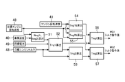
- FIG. 2 is a control block diagram of target engine operating point and target power calculation.
- FIG. 3 is a control block diagram for calculating the torque command value of the motor generator.
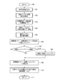
- FIG. 4 is a control flowchart for calculating the target engine operating point.
- FIG. 5 is a control flowchart for calculating the torque command value of the motor generator.
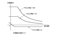
- FIG. 6 is a target driving force search map based on the vehicle speed and the accelerator opening.
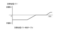
- FIG. 7 is a target charge / discharge power search table according to the state of charge of the battery.
- FIG. 8 is a target engine operating point search map composed of engine torque and engine speed.
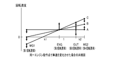
- FIG. 9 is a collinear diagram when the vehicle speed is changed at the same engine operating point.
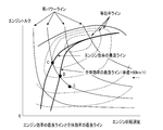
- FIG. 10 is a diagram showing the best line for engine efficiency and the best line for overall efficiency in a target engine operating point search map composed of engine torque and engine speed.
- FIG. 11 is a diagram showing each efficiency on the equal power line composed of the efficiency and the engine speed.
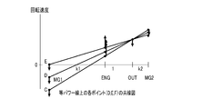
- FIG. 12 is a collinear diagram of each point (D, E, F) on the equal power line.
- FIG. 13 is a collinear diagram of the LOW gear ratio state.
- FIG. 14 is a collinear diagram of the intermediate gear ratio state.
- FIG. 15 is a collinear diagram of the HIGH gear ratio state.
- FIG. 16 is a collinear diagram in a state where power circulation occurs.
- FIG. 17 is a power loss search map based on vehicle speed and target driving force.
- reference numeral 1 denotes a hybrid vehicle drive control device.
- the drive control apparatus 1 for a hybrid vehicle includes, as a drive system, an output shaft 3 of an internal combustion engine 2 that generates a drive force by combustion of fuel, and a first motor that generates a drive force by electricity and generates electric energy by drive.
- a differential gear mechanism 8 that is a connected power transmission mechanism.
- the internal combustion engine 2 includes an air amount adjusting means 9 such as a throttle valve that adjusts the amount of air to be sucked in accordance with the accelerator opening (the amount of depression of the accelerator pedal), and fuel that supplies fuel corresponding to the amount of air to be sucked in.
- a fuel supply means 10 such as an injection valve and an ignition means 11 such as an ignition device for igniting the fuel are provided.
- the combustion state of the fuel is controlled by the air amount adjusting means 9, the fuel supply means 10 and the ignition means 11, and a driving force is generated by the combustion of the fuel.
- the first motor generator 4 includes a first motor rotor shaft 12, a first motor rotor 13, and a first motor stator 14.
- the second motor generator 5 includes a second motor rotor shaft 15, a second motor rotor 16, and a second motor stator 17.
- the first motor stator 14 of the first motor generator 4 is connected to the first inverter 18.
- the second motor stator 17 of the second motor generator 5 is connected to the second inverter 19.
- the power terminals of the first inverter 18 and the second inverter 19 are connected to the battery 20.
- the battery 20 is power storage means that can exchange power between the first motor generator 4 and the second motor generator 5.
- the first motor generator 4 and the second motor generator 5 control the amount of electricity supplied from the battery 20 by the first inverter 18 and the second inverter 19, respectively, and generate driving force by the supplied electricity. At the same time, electric energy is generated by the driving force from the driving wheel 6 during regeneration, and the battery 20 is charged with the generated electric energy.
- the differential gear mechanism 8 includes a first planetary gear mechanism 21 and a second planetary gear mechanism 22.
- the first planetary gear mechanism 21 includes a first sun gear 23, a first planetary carrier 25 that supports a first planetary gear 24 that meshes with the first sun gear 23, and a first ring gear 26 that meshes with the first planetary gear 24.
- the second planetary gear mechanism 22 includes a second sun gear 27, a second planetary carrier 29 that supports a second planetary gear 28 that meshes with the second sun gear 27, and a second ring gear 30 that meshes with the second planetary gear 28. It has.
- the differential gear mechanism 8 is configured such that the rotation center lines of the rotating elements of the first planetary gear mechanism 21 and the second planetary gear mechanism 22 are arranged on the same axis, and between the internal combustion engine 2 and the first planetary gear mechanism 21.
- the first motor generator 4 is disposed on the second planetary gear mechanism 22, and the second motor generator 5 is disposed on the second planetary gear mechanism 22 on the side away from the internal combustion engine 2.
- the second motor generator 5 has a performance capable of running the vehicle with only a single output.
- the first motor rotor shaft 12 of the first motor generator 4 is connected to the first sun gear 23 of the first planetary gear mechanism 21.
- the first planetary carrier 25 of the first planetary gear mechanism 21 and the second sun gear 27 of the second planetary gear mechanism 22 are coupled and connected to the output shaft 3 of the internal combustion engine 2 via the one-way clutch 31.
- the first ring gear 26 of the first planetary gear mechanism 21 and the second planetary carrier 29 of the second planetary gear mechanism 22 are coupled and coupled to the output unit 32.
- the output unit 32 is connected to the drive shaft 7 via an output transmission mechanism 33 such as a gear or a chain.
- the second motor rotor shaft 15 of the second motor generator 5 is connected to the second ring gear 30 of the second planetary gear mechanism 9.
- the one-way clutch 31 is a mechanism that fixes the output shaft 3 of the internal combustion engine 2 so as to rotate only in the output direction, and prevents the output shaft 3 of the internal combustion engine 2 from reversing.
- the driving power of the second motor generator 5 is transmitted as the driving power of the output unit 32 via the reaction force of the one-way clutch 31.
- the hybrid vehicle outputs the power generated by the internal combustion engine 2, the first motor generator 4, and the second motor generator 5 to the drive shaft 7 via the first planetary gear mechanism 21 and the second planetary gear mechanism 21. Then, the driving wheel 6 is driven.
- the hybrid vehicle transmits the driving force from the driving wheels 6 to the first motor generator 4 and the second motor generator 5 via the first planetary gear mechanism 21 and the second planetary gear mechanism 22, Electric energy is generated to charge the battery 20.
- the differential gear mechanism 8 has four rotating elements 34-37.
- the first rotating element 34 includes the first sun gear 23 of the first planetary gear mechanism 21.
- the second rotating element 35 is formed by combining the first planetary carrier 25 of the first planetary gear mechanism 21 and the second sun gear 27 of the second planetary gear mechanism 22.
- the third rotating element 36 is formed by coupling the first ring gear 26 of the first planetary gear mechanism 21 and the second planetary carrier 29 of the second planetary gear mechanism 22.
- the fourth rotating element 37 includes the second ring gear 30 of the second planetary gear mechanism 22.
- the differential gear mechanism 8 includes four rotating elements 34 to 37 on a collinear chart in which the rotational speeds of the four rotating elements 34 to 37 can be represented by straight lines.
- MG1 indicates the first motor generator 4
- MG2 indicates the second motor generator 5
- ENG indicates the internal combustion engine 2
- OUT indicates the output unit 32.
- the first motor rotor shaft 12 of the first motor generator 4 is connected to the first rotating element 34.
- the output shaft 3 of the internal combustion engine 2 is connected to the second rotation element 35 via a one-way clutch 31.
- An output unit 32 is connected to the third rotation element 36.
- the output shaft 32 is connected to the drive shaft 7 via an output transmission mechanism 33.
- a second motor rotor shaft 15 of the second motor generator 5 is connected to the fourth rotating element 37.
- the differential gear mechanism 8 has four rotating elements 34 to 37 connected to the output shaft 3, the first motor generator 4, the second motor generator 5, and the drive shaft 7, respectively. Power is exchanged among the output shaft 3, the first motor generator 4, the second motor generator 5, and the drive shaft 7. Therefore, the drive control device 1 is a “4-axis” control method.
- an air amount adjusting unit 9, a fuel supply unit 10, an ignition unit 11, a first inverter 18, and a second inverter 19 are connected to a drive control unit 38.
- the drive control unit 38 is connected with an accelerator opening degree detection means 39, a vehicle speed detection means 40, an engine rotation speed detection means 41, and a battery charge state detection means 42.
- the accelerator opening detection means 39 detects the accelerator opening that is the amount of depression of the accelerator pedal.
- the vehicle speed detection means 40 detects the vehicle speed (vehicle speed) of the hybrid vehicle.
- the engine speed detection means 41 detects the engine speed of the internal combustion engine 2.
- the battery charge state detection means 42 detects the charge state SOC of the battery 20.
- the drive control unit 38 includes a target drive force setting unit 43, a target drive power setting unit 44, a target charge / discharge power setting unit 45, a power loss estimation unit 46, a target engine power calculation unit 47, and a target engine.
- An operating point setting unit 48, a target power setting unit 49, and a motor torque command value calculation unit 50 are provided.
- the target driving force setting means 43 drives the hybrid vehicle based on the accelerator opening detected by the accelerator opening detecting means 39 and the vehicle speed detected by the vehicle speed detecting means 40, as shown in FIG.
- the target driving force for this purpose is determined by searching the target driving force search map shown in FIG.
- the target drive power setting unit 44 sets the target drive power based on the vehicle speed detected by the vehicle speed detection unit 40 and the target drive force set by the target drive force setting unit 43.
- the target charge / discharge power setting means 45 sets the target charge / discharge power based on at least the state of charge SOC of the battery 20 detected by the battery charge state detection means 42. In this embodiment, the target charge / discharge power is searched and set by the target charge / discharge power search table shown in FIG. 7 according to the state of charge SOC of the battery 20 and the vehicle speed.
- the target charge / discharge power is set such that the absolute value decreases as the vehicle speed decreases.
- the power loss estimation unit 46 calculates an estimated power that is a power loss based on the vehicle speed detected by the vehicle speed detection unit 40 and the target driving force set by the target driving force setting unit 43.
- the power loss estimation unit 46 includes a power loss search map in which estimated power as power loss is set (FIG. 17). As shown in FIG. 17, the estimated power as the power loss increases as the target driving force increases, and the increase rate increases as the target driving force increases. Further, the estimated power as the power loss increases as the vehicle speed increases, and the target driving force that takes the maximum value decreases as the vehicle speed increases.
- the target engine power calculation means 47 is a target drive power set by the target drive power setting means 44, a target charge / discharge power set by the target charge / discharge power setting means 45, and a power loss calculated by the power loss estimation means 46.
- the target engine power is calculated based on the estimated power. In this embodiment, the target engine power is obtained by subtracting the target charge / discharge power from the target drive power and adding the estimated power.
- the target engine operating point setting means 48 sets a target engine operating point (target engine rotational speed and target engine torque) from the target engine power and the overall system efficiency of the drive control device 1. In this embodiment, the vehicle speed is searched for and set by the target engine operating point search map shown in FIG.
- the target power setting means 49 is based on the target drive power set by the target drive power setting means 44 and the target engine power set by the target engine power calculation means 46, and the target value of input / output power from the battery 20 Set a target power that is
- the motor torque command value calculation means 50 sets the torque command values of the first motor generator 4 and the second motor generator 5.
- the torque command value of the first motor generator 4 and the torque command value of the second motor generator 5 by the motor torque command value calculating means 50 are obtained by the first to seventh calculators 51 to 57, respectively.
- MG 1 indicates the first motor generator 4
- MG 2 indicates the second motor generator 5.
- the first calculation unit 51 The target rotational speed Nmg1t of the first motor generator 4 and the target rotational speed Nmg2t of the second motor generator 5 are calculated.
- the second calculation unit 52 is set by the target power setting means 49 and the target rotation speed Nmg1t of the first motor generator 4 and the target rotation speed Nmg2t of the second motor generator 5 calculated by the first calculation unit 51. Based on the target power and the target engine torque set by the target engine operating point setting means 48, the basic torque Tmg1i of the first motor generator 4 is calculated.
- the third calculator 53 uses the basic torque Tmg1i of the first motor generator 4 calculated by the second calculator 52 and the target engine torque set by the target engine operating point setting means 48 to generate a second motor generator. 6 basic torque Tmg2i is calculated.
- the fourth calculation unit 54 determines the feedback correction torque of the first motor generator 4 based on the engine speed detected by the engine speed detecting means 41 and the target engine speed set by the target engine operating point setting means 48. Tmg1fb is calculated.
- the fifth calculator 55 calculates the feedback correction torque of the second motor generator 5 based on the engine speed detected by the engine speed detector 41 and the target engine speed set by the target engine operating point setting means 48. Tmg2fb is calculated.
- the sixth calculator 56 uses the basic torque Tmg1i of the first motor generator 4 calculated by the second calculator 52 and the feedback correction torque Tmg1fb of the first motor generator 4 calculated by the fourth calculator 54. The torque command value Tmg1 of the first motor generator 4 is calculated.
- the seventh calculation unit 57 uses the basic torque Tmg2i of the second motor generator 5 calculated by the third calculation unit 53 and the feedback correction torque Tmg2fb of the second motor generator 5 calculated by the fifth calculation unit 55.
- the torque command value Tmg2 of the second motor generator 6 is calculated.
- the hybrid vehicle drive control device 1 is configured so that the internal combustion engine 2 operates at a target engine operating point (target engine speed and target engine torque) set by the target engine operating point setting means 48 by the drive control unit 38.
- the driving state of the air amount adjusting means 9, the fuel supply means 10 and the ignition means 11 is controlled.
- the drive control unit 38 first sets the torque command value set by the motor torque command value calculating unit 50 so that the state of charge (SOC) of the battery 20 becomes the target power set by the target power setting unit 49.
- SOC state of charge
- the hybrid vehicle drive control device 1 determines the target engine operating point (target engine speed, target engine torque from the driver's accelerator operation amount and vehicle speed. ) And the torque command values of the first motor generator 4 and the second motor generator 5 are calculated based on the target engine operating point as shown in the control flowchart for calculating the motor torque command value in FIG. To do.
- the accelerator opening detected by the accelerator opening detecting means 39 the vehicle speed detected by the vehicle speed detecting means 40, Various signals of the engine rotation speed detected by the engine rotation speed detection means 41 and the state of charge SOC of the battery 20 detected by the battery charge state detection means 42 are taken in (101), and the vehicle speed is calculated from the target driving force detection map (see FIG. 6). And a target driving force corresponding to the accelerator opening is calculated (102).
- step 104 in order to control the state of charge SOC of the battery 20 within the normal use range, a target charge / discharge amount is calculated from a target charge / discharge power search table shown in FIG.
- the target charge / discharge power is increased to the charge side so as to prevent overdischarge of the battery 20.
- the target charge / discharge power is increased to the discharge side so as to prevent overcharge.
- step 105 the estimated power value of the power loss in the first motor generator 4 and the second motor generator 5 is searched from the power loss search map shown in FIG. At this time, since the operating points of the first motor generator 4 and the second motor generator 5 are not yet determined, the power loss is calculated from the power loss search map of the first motor generator 4 and the second motor generator 5. I can't do it. Therefore, an approximate value of power loss is set in advance using the vehicle speed and the target driving force as parameters, and is calculated by searching the power loss search map.
- the target engine power to be output by the internal combustion engine 2 is calculated from the target drive power, the target charge / discharge power, and the estimated power of the power loss (106).
- the power to be output from the internal combustion engine 2 is a value obtained by adding (subtracting in the case of discharging) the power necessary for charging the battery 20 to the power necessary for driving the hybrid vehicle.
- the target engine power is calculated by subtracting the target charge / discharge power from the target drive power and adding the power loss.
- step 109 the upper limit value of the target engine power is limited.
- the upper limit value is the maximum output value that the internal combustion engine 2 can output.
- step 109 the target power is calculated by subtracting the target engine power from the target drive power.
- the target power is a value that means the assist power by the power of the battery 20.
- the target power is a value that means the charge power to the battery 20.
- the target engine operating point search map (FIG. 8) is a power transmission constituted by the differential gear mechanism 8, the first motor generator 4 and the second motor generator 5 for the efficiency of the internal combustion engine 2 on the equal power line.
- the line that selects and connects the points at which the overall efficiency, which takes the system efficiency into consideration, for each power is connected is set as the target engine operating point line.
- Each target engine operating point line is set for each vehicle speed (in FIG. 8, 40 km / h, 80 km / h, 120 km / h).
- the set value of the target engine operating point line may be obtained experimentally or calculated from the efficiency of the internal combustion engine 2, the first motor generator 4, and the second motor generator 5. Note that the target engine operating point line is set to move to the high rotation side as the vehicle speed increases.
- the first motor generator 4 operates as an electric motor
- the second motor generator 5 operates as a generator. Decreases the efficiency. Therefore, as indicated by a point C in FIG. 11, the efficiency of the power transmission system is lowered even if the efficiency of the internal combustion engine 2 is good, and the overall efficiency is lowered. Therefore, in order to prevent the power circulation from occurring in the high vehicle speed range, the rotational speed of the first motor generator 4 may be set to 0 or more as shown in E of the alignment chart shown in FIG.
- the engine operating point moves toward the higher engine rotation speed of the internal combustion engine 2, so that the efficiency of the internal combustion engine 2 is improved even if the efficiency of the power transmission system is improved, as indicated by the point E in FIG. As a result, the overall efficiency is lowered. Therefore, as shown in FIG. 11, the point with high overall efficiency is D between the two, and if this point is set as the target engine operating point, the most efficient operation is possible. As described above, FIG. 10 shows the three engine operating points C, D, and E on the target engine operating point search map. When the vehicle speed is high, the operating point with the best overall efficiency is the engine efficiency. It turns out that it moves to the high rotation side from the best operating point.
- the target rotational speed Nmg1t of the first motor generator 4 and the target rotational speed Nmg2t of the second motor generator 5 are expressed by the following equation (1), Calculate by (2).
- the arithmetic expressions (1) and (2) are obtained from the relationship between the rotational speeds of the first planetary gear mechanism 21 and the second planetary gear mechanism 22.
- ⁇ Nmg1t (Net-No) * k1 + Net (1)
- Nmg2t (No-Net) * k2 + No (2)
- k1 and k2 are values determined by the gear ratio of the first planetary gear mechanism 21 and the second planetary gear mechanism 22 as described later.
- step 202 the target rotational speed Nmg1t of the first motor generator 4 and the target rotational speed Nmg2t of the second motor generator 5 obtained in step 201, and the value Pbatt obtained by adding power loss to the target charge / discharge power, From the target engine torque Tet, the basic torque Tmg1i of the first motor generator 4 is calculated by the following calculation formula (3).
- Tmg1i (Pbatt * 60 / 2 ⁇ Nmg2t * Tet / k2) / (Nmg1t + Nmg2t * (1 + k1) / k2) (3)
- This arithmetic expression (3) includes the following torque balance expression (4) representing the balance of torque input to the first planetary gear mechanism 21 and the second planetary gear mechanism 22, and the first motor generator 4 and the first Solving a certain simultaneous equation from the power balance equation (5) indicating that the power generated or consumed by the two motor generators 5 is equal to the input / output power to the battery 20 plus the power loss (Pbatt).
- Te + (1 + k1) * Tmg1 k2 * Tmg2 (4)
- Nmg1 * Tmg1 * 2 ⁇ / 60 + Nmg2 * Tmg2 * 2 ⁇ / 60 Pbatt ′ (5)
- step 203 the basic torque Tmg2i of the second motor generator 5 is calculated from the basic torque Tmg1i of the first motor generator 4 and the target engine torque Tet by the following equation (6).
- Tmg2i (Te + (1 + k1) * Tmg1i) / k2 (6) This equation is derived from the above equation (4).
- step 204 in order to bring the engine rotation speed closer to the target, the deviation of the engine rotation speed Ne from the target engine rotation speed Net is multiplied by a predetermined feedback gain, and the feedback of the first motor generator 4 is performed.
- the correction torque Tmg1fb and the feedback correction torque Tmg2fb of the second motor generator 5 are calculated.
- step 205 the feedback correction torques Tmg1fb and Tmg2fb of the first motor generator 4 and the second motor generator 5 are added to the basic torques Tmg1i and Tmg2i, and the first motor generator 4 and the second motor generator 5 are added.
- the torque command values Tmg1 and Tmg2 that are control command values are calculated, and the process returns (206).
- the drive control unit 38 controls the first motor generator 4 and the second motor generator 5 according to the torque command values Tmg1 and Tmg2, thereby charging and discharging the battery 20 while outputting a target driving force. Can be set as a target value.
- 13 to 16 show collinear diagrams in typical operation states.
- the four rotating elements 34 to 37 of the differential gear mechanism 8 including the first planetary gear mechanism 21 and the second planetary gear mechanism 22 are arranged in order in the first motor generator 4 (MG1).
- a second rotating element 35 connected to the internal combustion engine 2 (ENG), a third rotating element 36 connected to the drive shaft 7 (OUT), and a second motor generator 5 (MG2). ) Are connected in the order of the fourth rotating elements 37, and the lever ratio between the rotating elements 34 to 37 is set as k1: 1: k2 in the same order.
- the values k1 and k2 determined by the gear ratio of the differential gear mechanism 8 including the first planetary gear mechanism 21 and the second planetary gear mechanism 22 are defined as follows.
- the rotational speed is the direction in which the rotation direction of the output shaft 3 of the internal combustion engine 2 is the positive direction
- the torque input / output to / from each shaft is the direction in which the torque in the same direction as that of the output shaft 3 of the internal combustion engine 2 is input
- a torque for driving the hybrid vehicle forward is output (driving when the vehicle is moving forward, decelerating when the vehicle is moving backward).
- the first inverter 18 and the second inverter 19 and the first motor generator 4 and the second motor generator 5 cause loss due to heat generation, so the efficiency when converting between electrical energy and mechanical energy is not 100%.
- the description will be made assuming that there is no loss.
- control is performed so that extra power is generated by the amount of energy lost due to the loss.
- the hybrid vehicle drive control device 1 has the target drive force setting means 43 for setting the target drive force based on the accelerator opening and the vehicle speed, and the target drive based on the vehicle speed and the target drive force.
- Target engine power from target drive power setting means 44 for setting power target charge / discharge power setting means 45 for setting target charge / discharge power based on at least the state of charge of battery 20, and target charge / discharge power
- Motor torque command value calculation means 49 for setting each torque command value, and the motor torque
- the command value calculation means 49 uses the torque balance equation including the target engine torque obtained from the target engine operating point and the power balance equation including the target charge / discharge power to use the plurality of first motor generators 4 and second motor generators. 5 is calculated.
- the torque correction value (feedback correction torque) of the plurality of first motor generators 4 and the torque correction value (feedback correction torque) of the second motor generator 5 Is calculated based on the deviation between the actual engine speed and the target engine speed, and the ratio between the torque correction value of the first motor generator 4 and the torque correction value of the second motor generator 5 is calculated as the power A predetermined ratio based on the lever ratio of the differential gear mechanism 8 of the input / output device is set.
- the drive control apparatus 1 of the hybrid vehicle cancels out the torque fluctuation of the internal combustion engine 2 using the torque balance formula focusing on the torque change with the drive shaft 7 as a fulcrum.
- the differential gear mechanism 8 as a power input / output device has four rotating elements 34 to 37 connected to the first rotating element 34 and the internal combustion engine 2 sequentially connected to the first motor generator 4 in the alignment chart.
- the second rotation element 35, the third rotation element 36 connected to the drive shaft 7, and the fourth rotation element 37 connected to the second motor generator 5 are arranged in this order, and the mutual lever ratio between these rotation elements In the same order as k1: 1: k2, and the torque correction value of the first motor generator 4 and the torque correction value of the second motor generator 5 are multiplied by the torque correction value of the first motor generator 4 by k1.
- the value is set so as to maintain a relationship in which the value obtained by multiplying the torque correction value of the second motor generator 5 by 1 + k2 is equal.
- the torque balance type can be suitably used when the differential gear mechanism 8 having the same four rotating elements 34 to 37 and having different lever ratios is configured.
- the drive control device 1 sets the feedback correction amounts to be set in the torque command values of the plurality of first motor generators 4 and the second motor generator 5 respectively, to the plurality of first motor generators 4 and the second motor generators. 5 is set in association with the gear ratio or lever ratio of the differential gear mechanism 8 having four rotating elements 34 to 37 respectively connected to the drive shaft 7 and the internal combustion engine 2.
- the target torque (torque command value) of each of the plurality of first motor generators 4 and the second motor generator 5 and the target engine torque of the internal combustion engine 2 are Is based on a lever ratio based on a gear ratio of a differential gear mechanism 8 which is a power input / output device that mechanically connects the plurality of first motor generators 4 and second motor generators 5 and the internal combustion engine 2 to each other. Is balanced.
- the motor torque command value calculating means 50 uses a torque balance equation including a target engine torque obtained from a target engine operating point and a power balance equation including a target charge / discharge power, and a plurality of first motor generators 4 and second motor generators 4 and 2.
- the plurality of first motor generators 4 and the second motors so as to calculate the torque command values of the respective motor generators 5 and to converge the actual engine rotational speed to the target engine rotational speed obtained from the target engine operating point. It is possible to perform respective feedback corrections on the torque command value of the generator 5.
- the hybrid vehicle drive control device 1 that calculates the torque command value can control the plurality of first motor generators 4 and the second motor generator 5 when the battery 20 is charged and discharged.
- the engine operating point of the internal combustion engine 2 it is possible to achieve both a target driving force and a target charge / discharge.
- the engine speed can be quickly converged to the target value. Since the engine operating point can be combined with the target operating point, an appropriate operating state can be achieved.
- the hybrid vehicle drive control device 1 includes a plurality of second control devices when the battery 20 is charged and discharged in a hybrid system including the internal combustion engine 2, the plurality of first motor generators 4, and the second motor generator 5.
- a control of the one motor generator 4 and the second motor generator 5 in consideration of the engine operating point of the internal combustion engine 2, when performing a control that ensures both a target driving force and a target charge / discharge, It is possible to improve drivability and running feeling by optimizing the torque fluctuation of the internal combustion engine 2 so as not to affect the driving torque.
- the hybrid vehicle drive control device 1 includes a power loss estimation unit 46 that calculates an estimated power that is a power loss based on the vehicle speed and the target driving force.
- the target engine power calculation unit 47 The target engine power is calculated based on the target charge / discharge power and the estimated power that is the power loss calculated by the power loss estimating means 46.
- the drive control apparatus 1 of this hybrid vehicle can improve the control accuracy of the state of charge SOC of the battery 20 in consideration of the power loss of the plurality of first motor generators 4 and the second motor generator 5. it can.
- the drive control apparatus 1 for the hybrid vehicle calculates the target engine operating point and the target power based on the target engine power calculated in consideration of power loss, and the plurality of first motor generators 4 and the second motor generator 4 Since the respective torque command values of the motor generator 5 are calculated, errors due to variations in power loss due to differences in vehicle speed and target driving force are reduced, and the control accuracy of the state of charge SOC of the battery 20 is improved to achieve the target. While ensuring the charge / discharge, it is possible to achieve both of the target driving force ensuring.
- This invention can improve the control accuracy of the state of charge of the battery in consideration of the power loss of a plurality of motor generators, and can be applied to the driving force control of a hybrid vehicle.
Landscapes
- Engineering & Computer Science (AREA)
- Chemical & Material Sciences (AREA)
- Combustion & Propulsion (AREA)
- Transportation (AREA)
- Mechanical Engineering (AREA)
- Automation & Control Theory (AREA)
- Electric Propulsion And Braking For Vehicles (AREA)
- Hybrid Electric Vehicles (AREA)
Abstract
Description
この従来技術では、前記内燃機関のエンジン動作点を停止を含めた任意の点に設定できるため、燃費を向上することができる。しかし、シリーズ方式ほどではないが、十分な駆動軸トルクを得るためには比較的大きなトルクを有する電動機が必要となるため、及びLOWギア比域で発電機と電動機との間での電力の受け渡し量が増加するため、電気的損失が大きくなり、未だ改善の余地がある。
この点を解決する方法としては、特許第3578451号公報、特開2004-15982号公報に開示されるものや、この発明の出願人による特開2002-281607号公報、特開2008-12992号公報に開示されるものがある。
特開2002-281607号公報の方法は、4つの回転要素を有する差動歯車機構の各回転要素に、内燃機関の出力軸、第一のモータジェネレータ(以下「MG1」と記す)、第二のモータジェネレータ(以下「MG2」と記す)、及び駆動輪に接続される駆動軸を接続し、内燃機関の動力とMG1、MG2の動力を合成して駆動軸に出力するものである。
そして、特開2002-281607号公報の方法は、共線図上で内側の回転要素に内燃機関の出力軸と駆動輪に接続される駆動軸とを配置し、共線図上で外側の回転要素にMG1(内燃機関側)とMG2(駆動軸側)とを配置することにより、内燃機関から駆動軸へ伝達される動力のうち、MG1及びMG2が受け持つ割合を少なくすることができるので、MG1、MG2を小型化できると共に駆動装置としての伝達効率を改善できる。これを「4軸式」と呼ぶこととする。
また、特許第3578451号公報も上記方法と同様であるが、さらに5つ目の回転要素を有し、この回転要素の回転を停止させるブレーキを設ける方法も提案している。
前記特開2008-12992号公報は、内燃機関と複数のモータジェネレータを備えたハイブリッド車両の駆動制御装置において、内燃機関のエンジン動作点に関してエンジン回転速度を高く設定するものであり、内燃機関の制御技術が開示されている。
上記の従来技術では、特許第3050125号公報に開示されるように、車両に要求される駆動力とバッテリの充電に要求される電力を加算して内燃機関が出力すべきパワーを算出し、そのパワーとなるエンジントルクとエンジン回転速度の組み合わせの中から、できるだけ効率が良いポイントを算出して目標エンジン動作点としている。そして、内燃機関のエンジン動作点が目標動作点となるように、MG1を制御してエンジン回転速度を制御している。
しかし、「4軸式」の場合には、駆動軸とMG2とが別の軸となり、MG2のトルクもトルクバランスに影響してエンジン回転速度制御に影響するため、上記「3軸式」の制御方法は使えないという不都合がある。
また、「4軸式」である上記特開2004-15982号公報では、バッテリヘの充放電の無い状態で走行する場合のMG1、MG2のトルクをトルクバランス式から算出し、MG1、MG2の回転速度をフィードバック制御してエンジン回転速度と駆動力を制御する方法が開示されている。
しかし、上記特開2004-15982号公報では、バッテリヘの充放電がある場合や、エンジントルクが変動した場合については言及していない。
前記特開2008-12992号公報では、内燃機関の動作点に関してエンジン回転速度を高く設定するものであり、内燃機関の制御技術が開示されているが、複数のモータジェネレータの制御は不明であり、さらに、バッテリとの充放電を行う場合の複数のモータジェネレータの制御は不明である。
前記特開2008-12992号公報では、内燃機関と複数のモータジェネレータを機械的に作動連結して、内燃機関の動作点を目標値に維持しながら複数のモータジェネレータを互いに関連させてトルクバランスをとって制御する必要があり、さらに、バッテリとの充放電を行う場合には、電力収支もバランスさせる必要がある。つまり、それら複数のモータジェネレータのトルクバランス及び電力収支のバランスを両立するように制御する必要がある。
さらに、前記特開2008-12992号公報では、複数のモータジェネレータを互いに関連させてトルクバランスをとって制御する際に、フィードバック制御を行っても、その制御内容によっては、内燃機関のトルク変動が駆動トルクに影響を及ぼしてしまう不都合がある。
そこで、この発明の出願人は、内燃機関の出力、MG1、MG2、の動力を合成して駆動輪に接続される駆動軸を駆動するハイブリッド車両において、アクセル操作量と車両速度をパラメータとする目標駆動力と、車両速度とから目標駆動パワーを求め、バッテリの充電状態SOCに基づいて目標充放電パワーを求めて目標駆動パワーに加算し目標エンジンパワーとして算出し、目標エンジンパワーから目標エンジン動作点を求め、目標駆動パワーと目標エンジンパワーの差からバッテリからの入出力電力の目標値である目標電力を求め、目標エンジントルクを含むトルクバランス式と、目標電力を含む電力バランス式からMG1のトルクとMG2のトルクの制御指令値(トルク指令値)を演算する駆動制御装置を考案した。
この方法によれば、目標とする駆動力を出力しながらバッテリの充電状態SOCを所定範囲に制御するための発電を行うことができる。
しかし、電力バランス式には、MG1、MG2の損失が考慮されていないため、その損失分を余分に発電する充電状態SOCまでにしか充電状態SOCが到達せず、目標とする充電状態SOCより実際の充電状態SOCが低くなってしまうという問題があった。この問題は、特に、MG1、MG2の損失が増加する高速走行時や高負荷走行時に顕著となった。
この発明は、電力損失を考慮して算出した目標エンジンパワーに基づいて、目標エンジン動作点および目標電力を算出し、複数のモータジェネレータのそれぞれのトルク指令値を算出することになるので、車両速度や目標駆動力の違いによる電力損失のばらつきによる誤差が少なくなり、バッテリの充電状態の制御精度を向上させて目標とする充放電を確保しつつ、目標とする駆動力確保との両立を可能とすることができる。
前記内燃機関2は、アクセル開度(アクセルペダルの踏み込み量)に対応して吸入する空気量を調整するスロットルバルブ等の空気量調整手段9と、吸入する空気量に対応する燃料を供給する燃料噴射弁等の燃料供給手段10と、燃料に着火する点火装置等の着火手段11とを備えている。内燃機関2は、空気量調整手段9と燃料供給手段10と着火手段11とにより燃料の燃焼状態を制御され、燃料の燃焼により駆動力を発生する。
前記第一のモータジェネレータ4は、第1モータロータ軸12と第1モータロータ13と第1モータステータ14とを備えている。前記第二のモータジェネレータ5は、第2モータロータ軸15と第2モータロータ16と第2モータステータ17とを備えている。第一のモータジェネレータ4の第1モータステータ14は、第1インバータ18に接続されている。第二のモータジェネレータ5の第2モータステータ17は、第2インバータ19に接続されている。
第1インバータ18と第2インバータ19との電源端子は、バッテリ20に接続されている。バッテリ20は、第一のモータジェネレータ4および第二のモータジェネレータ5との間で電力のやり取りが可能な蓄電手段である。第一のモータジェネレータ4と第二のモータジェネレータ5とは、それぞれ第1インバータ18と第2インバータ19とによりバッテリ20から供給される電気量を制御され、供給される電気により駆動力を発生するとともに、回生時の駆動輪6からの駆動力で電気エネルギを発生し、発生した電気エネルギをバッテリ20に充電する。
差動歯車機構8は、第1遊星歯車機構21と第2遊星歯車機構22との各回転要素の回転中心線を同一軸上に配置し、内燃機関2と第1遊星歯車機構21との間に第一のモータジェネレータ4を配置し、第2遊星歯車機構22の内燃機関2から離れる側に第二のモータジェネレータ5を配置している。第二のモータジェネレータ5は、単独出力のみで車両を走行させることができる性能を備えている。
第1遊星歯車機構21の第1サンギア23には、第一のモータジェネレータ4の第1モータロータ軸12を接続している。第1遊星歯車機構21の第1プラネタリキャリア25と第2遊星歯車機構22の第2サンギア27とは、結合して内燃機関2の出力軸3にワンウェィクラッチ31を介して接続している。第1遊星歯車機構21の第1リングギア26と第2遊星歯車機構22の第2プラネタリキャリア29とは、結合して出力部32に連結している。出力部32は、歯車やチェーン等の出力伝達機構33を介して前記駆動軸7に接続している。第2遊星歯車機構9の第2リングギア30には、第二のモータジェネレータ5の第2モータロータ軸15を接続している。
前記ワンウェイクラッチ31は、内燃機関2の出力軸3が出力方向にしか回転しないように固定する機構であり、内燃機関2の出力軸3が逆転することを防止する。第二のモータジェネレータ5の駆動パワーは、ワンウェイクラッチ31の反力を介して出力部32の駆動パワーとして伝達される。
ハイブリッド車両は、内燃機関2と第一のモータジェネレータ4と第二のモータジェネレータ5とが発生する動力を、第1遊星歯車機構21と第2遊星歯車機構21とを介して駆動軸7に出力し、駆動輪6を駆動する。また、ハイブリッド車両は、駆動輪6からの駆動力を、第1遊星歯車機構21と第2遊星歯車機構22とを介して第一のモータジェネレータ4と第二のモータジェネレータ5とに伝達し、電気エネルギを発生してバッテリ20を充電する。
差動歯車機構8は、図9、図12~図16に示すように、4つの回転要素34~37の回転速度を直線で表すことができる共線図上において、4つの回転要素34~37を一端(各図の左側)から他端(各図の右側)に向かって順番に、第1回転要素34、第2回転要素35、第3回転要素36、第4回転要素37として設定している。4つの回転要素34~37間の距離の比は、k1:1:k2、で表される。なお、各図の記載において、MG1は第一のモータジェネレータ4、MG2は第二のモータジェネレータ5、ENGは内燃機関2、OUTは出力部32を示している。
第1回転要素34には、第一のモータジェネレータ4の第1モータロータ軸12を接続している。第2回転要素35には、内燃機関2の出力軸3をワンウェイクラッチ31を介して接続している。第3回転要素36には、出力部32を接続している。この出力部32には、出力伝達機構33を介して駆動軸7を接続している。第4回転要素37には、第二のモータジェネレータ5の第2モータロータ軸15を接続している。
これにより、差動歯車機構8は、出力軸3、第一のモータジェネレータ4、第二のモータジェネレータ5、及び駆動軸7にそれぞれ連結された4つの回転要素34~37を有し、内燃機関2の出力軸3、第一のモータジェネレータ4、第二のモータジェネレータ5、及び駆動軸7との間で動力の授受を行う。よって、駆動制御装置1は、「4軸式」の制御方式である。
前記アクセル開度検出手段39は、アクセルペダルの踏み込み量であるアクセル開度を検出する。前記車両速度検出手段40は、ハイブリッド車両の車両速度(車速)を検出する。前記エンジン回転数検出手段41は、内燃機関2のエンジン回転速度を検出する。バッテリ充電状態検出手段42は、バッテリ20の充電状態SOCを検出する。
前記目標駆動力設定手段43は、図2に示すように、アクセル開度検出手段39により検出されたアクセル開度と車両速度検出手段40により検出された車両速度とに基づいて、ハイブリッド車両を駆動するための目標駆動力を、図6に示す目標駆動力検索マップにより検索して決定する。目標駆動力は、アクセル開度=0での高車速域ではエンジンブレーキ相当の減速方向の駆動力となるように負の値に設定し、車速が低い領域ではクリープ走行ができるように正の値に設定する。
前記目標駆動パワー設定手段44は、車両速度検出手段40により検出された車両速度と目標駆動力設定手段43により設定された目標駆動力とに基づいて、目標駆動パワーを設定する。
前記目標充放電パワー設定手段45は、少なくともバッテリ充電状態検出手段42により検出されたバッテリ20の充電状態SOCに基づいて、目標充放電パワーを設定する。この実施例においては、バッテリ20の充電状態SOCと車両速度に応じて、目標充放電パワーを、図7に示す目標充放電パワー検索テーブルにより検索して設定する。目標充放電パワーは、車両速度が低くなるほど、絶対値が小さくなるように設定する。
前記電力損失推測手段46は、車両速度検出手段40により検出された車両速度と目標駆動力設定手段43により設定された目標駆動力とに基づいて、電力損失となる推定パワーを算出する。電力損失推定手段46は、電力損失としての推定パワーを設定した電力損失検索マップを備える(図17)。電力損失としての推定パワーは、図17に示すように、目標駆動力が増大するにつれて増加し、その増加率は、目標駆動力が増大するにつれて増加する。また、電力損失としての推定パワーは、車両速度が高くなるほど増加するとともに、その最大値をとる目標駆動力は、車両速度が高くなるほど小さくなる。
前記目標エンジンパワー算出手段47は、目標駆動パワー設定手段44により設定された目標駆動パワーと目標充放電パワー設定手段45により設定された目標充放電パワーと電力損失推測手段46により算出された電力損失となる推定パワーとに基づいて、目標エンジンパワーを算出する。この実施例においては、目標駆動パワーから目標充放電パワーを減算して推定パワーを加算することにより、目標エンジンパワーを得る。
前記目標エンジン動作点設定手段48は、目標エンジンパワーと駆動制御装置1のシステム全体効率とから目標エンジン動作点(目標エンジン回転速度と目標エンジントルク)を設定する。この実施例においては、図8に示す目標エンジン動作点検索マップにより車両速度を考慮して検索して設定する。
前記目標電力設定手段49は、目標駆動パワー設定手段44により設定された目標駆動パワーと目標エンジンパワー算出手段46により設定された目標エンジンパワーとに基づいて、バッテリ20からの入出力電力の目標値である目標電力を設定する。
前記モータトルク指令値演算手段50は、第一のモータジェネレータ4、第二のモータジェネレータ5の、それぞれのトルク指令値を設定する。
前記第1算出部51は、目標エンジン動作点設定手段48により設定された目標エンジン回転速度と車両速度検出手段40により検出された車両速度とによって、エンジン回転速度が目標エンジン回転速度となった場合の第一のモータジェネレータ4の目標回転速度Nmg1t及び第二のモータジェネレータ5の目標回転速度Nmg2tを算出する。
前記第2算出部52は、第1算出部51により算出された第一のモータジェネレータ4の目標回転速度Nmg1t及び第二のモータジェネレータ5の目標回転速度Nmg2tと目標電力設定手段49により設定された目標電力と目標エンジン動作点設定手段48により設定された目標エンジントルクとによって、第一のモータジェネレータ4の基本トルクTmg1iを算出する。
前記第3算出部53は、第2算出部52により算出された第一のモータジェネレータ4の基本トルクTmg1iと目標エンジン動作点設定手段48により設定された目標エンジントルクとによって、第二のモータジェネレータ6の基本トルクTmg2iを算出する。
前記第4算出部54は、エンジン回転速度検出手段41により検出されたエンジン回転速度と目標エンジン動作点設定手段48により設定された目標エンジン回転速度とによって、第一のモータジェネレータ4のフィードバック補正トルクTmg1fbを算出する。
前記第5算出部55は、エンジン回転速度検出手段41により検出されたエンジン回転速度と目標エンジン動作点設定手段48により設定された目標エンジン回転速度とによって、第二のモータジェネレータ5のフィードバック補正トルクTmg2fbを算出する。
前記第6算出部56は、第2算出部52により算出された第一のモータジェネレータ4の基本トルクTmg1iと第4算出部54により算出された第一のモータジェネレータ4のフィードバック補正トルクTmg1fbとによって、第一のモータジェネレータ4のトルク指令値Tmg1を算出する。
前記第7算出部57は、第3算出部53により算出された第二のモータジェネレータ5の基本トルクTmg2iと第5算出部55により算出された第二のモータジェネレータ5のフィードバック補正トルクTmg2fbとによって、第二のモータジェネレータ6のトルク指令値Tmg2を算出する。
ハイブリッド車両の駆動制御装置1は、駆動制御部38によって、目標エンジン動作点設定手段48で設定された目標エンジン動作点(目標エンジン回転速度と目標エンジントルク)で内燃機関2が動作するように、空気量調整手段9と燃料供給手段10と着火手段11との駆動状態を制御する。また、駆動制御部38は、バッテリ20の充電状態(SOC)が目標電力設定手段49で設定された目標電力となるように、モータトルク指令値演算手段50で設定されたトルク指令値で第一のモータジェネレータ4及び第二のモータジェネレータ5の駆動状態を制御する。
目標駆動力は、アクセル開度=0での高車速域ではエンジンブレーキ相当の減速方向の駆動力となるように負の値に設定し、車速が低い領域ではクリープ走行ができるように正の値に設定する。
ついで、ステップ102で算出した目標駆動力と車両速度とを乗算して、目標駆動力でハイブリッド車両を駆動するのに必要な目標駆動パワーを算出し(103)、目標充放電パワー検索テーブル(図7参照)から目標充放電パワーを算出する(104)。
ステップ104では、バッテリ20の充電状態SOCを通常使用範囲内に制御するために、目標とする充放電量を図7に示す目標充放電パワー検索テーブルから算出する。バッテリ20の充電状態SOCが低い場合には、バッテリ20の過放電を防止するように目標充放電パワーを充電側に大きくしている。バッテリ20の充電状態SOCが高い場合には、過充電を防止するように目標充放電パワーを放電側に大きくしている。目標充放電パワーは、便宜上、放電側を正の値、充電側を負の値として取り扱う。
ステップ105では、図17に示す電力損失検索マップから第一のモータジェネレータ4及び第二のモータジェネレータ5での電力損失の推定パワー値を検索する。この時点では、第一のモータジェネレータ4及び第二のモータジェネレータ5の動作点を決める前であるため、第一のモータジェネレータ4及び第二のモータジェネレータ5の電力損失検索マップから電力損失を算出することはできない。そのため、車両速度と目標駆動力をパラメータとして予め電力損失の概算値を設定しておき、電力損失検索マップの検索により算出するようにしている。
更に、目標駆動パワーと目標充放電パワーと電力損失の推定パワーとから内燃機関2が出力すべき目標エンジンパワーを算出する(106)。内燃機関2が出力すべきパワーは、ハイブリッド車両の駆動に必要なパワーにバッテリ20の充電に必要なパワーを加算(放電の場合は減算)した値となる。ここでは、充電側の負の値として取り扱っているので、目標駆動パワーから目標充放電パワーを減算して電力損失を加算し、目標エンジンパワーを算出している。
次に、ステップ106で算出した目標エンジンパワーが上限値を越えているかを判断する(107)。この判断(107)がYESの場合は、上限値を目標エンジンパワーに置き換えて(108)、ステップ109に移行する。この判断(107)がNOの場合は、ステップ109に移行する。ステップ107、ステップ108では、目標エンジンパワーの上限値による制限を行う。上限値は、内燃機関2が出力可能な出力の最大値である。
ステップ109においては、目標駆動パワーから目標エンジンパワーを減算して目標電力を算出する。目標駆動パワーの方が目標エンジンパワーより大きい場合、目標電力はバッテリ20の電力によるアシストパワーを意味する値となる。また、目標エンジンパワーの方が目標駆動パワーより大きい場合には、目標電力はバッテリ20への充電電力を意味する値となる。
ステップ109の目標電力の算出後は、図8に示す目標エンジン動作点検索マップから車両速度に応じた目標エンジン動作点(目標エンジン回転速度及び目標エンジントルク)を算出し(110)、リターンする(111)。
これは、以下の理由による。
車両速度によらず同一のエンジン動作点を目標エンジン動作点とした場合、図9に示すように、車両速度が低い場合には第一のモータジェネレータ4の回転速度は正となり、第一のモータジェネレータ4が発電機、第二のモータジェネレータ5が電動機となる(A)。そして、車両速度が高くなるに連れて第一のモータジェネレータ4の回転速度は0に近づき(B)、さらに車両速度が高くなると第一のモータジェネレータ4の回転速度は負となる。この状態になると、第一のモータジェネレータ4は電動機として作動するとともに、第二のモータジェネレータ5は発電機として作動する(C)。
車両速度が低い場合(A、Bの状態)、パワーの循環は起きないので、目標エンジン動作点は、図8の車両速度=40km/hの目標エンジン動作点ラインのように、概ね内燃機関2の効率の良いポイントに近いものとなる。
しかし、車両速度が高い場合(Cの状態)になると、第一のモータジェネレータ4は電動機として作動するとともに、第二のモータジェネレータ5は発電機として作動し、パワー循環が発生するため動力伝達系の効率が低下する。従って、図11のCのポイントに示すように、内燃機関2の効率が良くても動力伝達系の効率が低下するため、全体としての効率が低下してしまう。
そこで、高車速域でパワー循環が発生しないようにするには、図12に示す共線図のEのように第一のモータジェネレータ4の回転速度を0以上にすればよい。しかし、そうすると、内燃機関2のエンジン回転速度が高くなる方へエンジン動作点が移動するので、図11のEのポイントに示すように、動力伝達系の効率が良くなっても内燃機関2の効率が大きく低下するので全体としての効率は低下してしまう。
従って、図11に示すように全体としての効率が良いポイントは両者の間のDとなり、このポイントを目標エンジン動作点とすれば最も効率のよい運転が可能となる。
以上、C、D、Eの3つのエンジン動作点を目標エンジン動作点検索マップ上に表したのが図10であり、車両速度が高い場合には全体効率が最良となる動作点がエンジン効率が最良となる動作点より高回転側に移動することが判る。
モータトルク指令値の算出において、図5に示すように、制御プログラムがスタート(200)すると、先ず、ステップ201において車両速度から第1遊星歯車機構21及び第2遊星歯車機構22が接続される駆動軸7の駆動軸回転速度Noを算出する。そして、エンジン回転速度Neが目標エンジン回転速度Netとなった場合の、第一のモータジェネレータ4の目標回転速度Nmg1tと第二のモータジェネレータ5の目標回転速度Nmg2tとを以下の式(1)、(2)により算出する。この演算式(1)、(2)は、第1遊星歯車機構21及び第2遊星歯車機構22の回転速度の関係から求められる。
・Nmg1t=(Net-No)*k1+Net………(1)
・Nmg2t=(No-Net)*k2+No………(2)
ここで、k1、k2は、後述するように第1遊星歯車機構21及び第2遊星歯車機構22のギア比により定まる値である。
・Tmg1i=(Pbatt*60/2π-Nmg2t*Tet/k2)/(Nmg1t+Nmg2t*(1+k1)/k2)………(3)
・Te+(1+k1)*Tmg1=k2*Tmg2………(4)
・Nmg1*Tmg1*2π/60+Nmg2*Tmg2*2π/60=Pbatt’………(5)
・Tmg2i=(Te+(1+k1)*Tmg1i)/k2………(6)
この式は上記式(4)から導き出したものである。
ここで、第1遊星歯車機構21及び第2遊星歯車機構22からなる差動歯車機構8のギア比により定まる値k1、k2は下記のように定義される。
k1=ZR1/ZS1
k2=ZS2/ZR2
ZS1:第1サンギア歯数
ZR1:第1リングギア歯数
ZS2:第2サンギア歯数
ZR2:第2リングギア歯数
第一のモータジェネレータ4及び第二のモータジェネレータ5による発電や力行(動力を駆動輪7に伝えて加速、または昇り勾配で均衡速度を保つこと)を行う場合、第1インバータ18及び第2インバータ19や第一のモータジェネレータ4及び第二のモータジェネレータ5での発熱による損失が発生するため、電気エネルギと機械的エネルギとの間で変換を行う場合の効率は100%ではないが、説明を簡単にするため損失は無いと仮定して説明する。現実として損失を考慮する場合には、損失により失われるエネルギの分だけ余分に発電するように制御する。
内燃機関2により走行し、第二のモータジェネレータ5の回転速度が0の状態である。この時の共線図を図13に示す。第二のモータジェネレータ5の回転速度は0であるため、電力は消費しない。従って、バッテリ20への充放電が無い場合には、第一のモータジェネレータ4で発電を行う必要はないため、第一のモータジェネレータ4のトルク指令値Tmg1は0となる。
また、出力軸3のエンジン回転速度と駆動軸7の駆動軸回転速度の比は、(1+k2)/k2、となる。
内燃機関2により走行し、第一のモータジェネレータ4及び第二のモータジェネレータ5の回転速度が正の状態である。この時の共線図を図14に示す。この場合、バッテリ20への充放電が無い場合、第一のモータジェネレータ4は回生となり、この回生電力を用いて第二のモータジェネレータ5を力行させる。
内燃機関2により走行し、第一のモータジェネレータ4の回転速度が0の状態である。この時の共線図を図15に示す。第一のモータジェネレータ4の回転速度は0であるため、回生はしない。従って、バッテリ20への充放電が無い場合には、第二のモータジェネレータ5での力行や回生は行わず、第二のモータジェネレータ5のトルク指令値Tmg2は0となる。
また、出力軸3のエンジン回転速度と駆動軸7の駆動軸回転速度の比は、k1/(1+k1)、となる。
HIGHギア比状態よりさらに車両速度が高い状態では、第一のモータジェネレータ4が逆回転する状態となる。この状態では、第一のモータジェネレータ4は力行となり、電力を消費する。従って、バッテリ20への充放電がない場合には、第二のモータジェネレータ5が回生となり発電を行う。
前記モータトルク指令値演算手段50は、フィードバック補正を行う際、複数の第一のモータジェネレータ4のトルク補正値(フィードバック補正トルク)と第二のモータジェネレータ5のトルク補正値(フィードバック補正トルク)とを、実際のエンジン回転速度と目標エンジン回転速度との偏差に基づいて算出するとともに、これら第一のモータジェネレータ4のトルク補正値と第二のモータジェネレータ5のトルク補正値との比を、動力入出力装置の差動歯車機構8のレバー比に基づく所定の比となるよう設定する。
これにより、ハイブリッド車両の駆動制御装置1は、駆動軸7を支点としてトルクの変化に注目したトルクバランス式を用いて、内燃機関2のトルク変動を打ち消しているので、内燃機関2にトルク変動が生じてもそれを駆動軸7のトルクに影響を与えないようにできる。
動力入出力装置としての前記差動歯車機構8は、4つの回転要素34~37を、共線図において順に第一のモータジェネレータ4に連結された第1回転要素34、内燃機関2に連結された第2回転要素35、駆動軸7に連結された第3回転要素36、第二のモータジェネレータ5に連結された第4回転要素37の順に並ぶとともに、それらの回転要素間の相互のレバー比を同順にk1:1:k2として設け、第一のモータジェネレータ4のトルク補正値と第二のモータジェネレータ5のトルク補正値とを、第一のモータジェネレータ4のトルク補正値にk1を乗じた値と第二のモータジェネレータ5のトルク補正値に1+k2を乗じた値とが等しくなる関係を維持するように設定する。トルクバランス式を、同様の4つの回転要素34~37を持つレバー比が異なる差動歯車機構8を構成する場合、好適に用いることができる。
また、駆動制御装置1は、複数の第一のモータジェネレータ4及び第二のモータジェネレータ5のトルク指令値にそれぞれ設定するフィードバック補正量を、複数の第一のモータジェネレータ4及び第二のモータジェネレータ5と駆動軸7と内燃機関2とにそれぞれ連結された4つの回転要素34~37を有する差動歯車機構8のギヤ比ないしレバー比に基づいて関連付けて設定する。
前記トルクバランス式では、前記(4)式に示すように、複数の第一のモータジェネレータ4及び第二のモータジェネレータ5のそれぞれの目標トルク(トルク指令値)と内燃機関2の目標エンジントルクとを、複数の第一のモータジェネレータ4及び第二のモータジェネレータ5と内燃機関2とを機械的に作動連結する動力入出力装置である差動歯車機構8のギヤ比に基づくレバー比に基づいて、バランスしている。
前記モータトルク指令値演算手段50は、目標エンジン動作点から求められる目標エンジントルクを含むトルクバランス式と目標充放電パワーを含む電力バランス式とを用いて複数の第一のモータジェネレータ4及び第二のモータジェネレータ5のそれぞれのトルク指令値を算出するとともに、目標エンジン動作点から求められる目標エンジン回転速度に実際のエンジン回転速度を収束させるように複数の第一のモータジェネレータ4及び第二のモータジェネレータ5のトルク指令値にそれぞれのフィードバック補正を行うことを可能とする。
また、このハイブリッド車両の駆動制御装置1は、内燃機関2と複数の第一のモータジェネレータ4及び第二のモータジェネレータ5を備えたハイブリッドシステムにおけるバッテリ20ヘの充放電がある場合の複数の第一のモータジェネレータ4及び第二のモータジェネレータ5の制御として、内燃機関2のエンジン動作点に配慮し、目標とする駆動力確保と目標とする充放電の確保を両立する制御を行う場合に、内燃機関2のトルク変動を駆動トルクに影響させないように最適にして、ドライバビリティや走行フィーリングを向上することができる。
また、このハイブリッド車両の駆動制御装置1は、電力損失を考慮して算出した目標エンジンパワーに基づいて、目標エンジン動作点および目標電力を算出し、複数の第一のモータジェネレータ4及び第二のモータジェネレータ5のそれぞれのトルク指令値を算出することになるので、車両速度や目標駆動力の違いによる電力損失のばらつきによる誤差が少なくなり、バッテリ20の充電状態SOCの制御精度を向上させて目標とする充放電を確保しつつ、目標とする駆動力確保との両立を可能とすることができる。
2 内燃機関
3 出力軸
4 第一のモータジェネレータ
5 第二のモータジェネレータ
7 駆動軸
8 差動歯車機構
18 第1インバータ
19 第2インバータ
20 バッテリ
21 第1遊星歯車機構
22 第2遊星歯車機構
31 ワンウェィクラッチ
32 出力部
34 第1回転要素
35 第2回転要素
36 第3回転要素
37 第4回転要素
38 駆動制御部
39 アクセル開度検出手段
40 車両速度検出手段
41 エンジン回転速度検出手段
42 バッテリ充電状態検出手段
43 目標駆動力設定手段
44 目標駆動パワー設定手段
45 目標充放電パワー設定手段
46 電力損失推測手段
47 目標エンジンパワー算出手段
48 目標エンジン動作点設定手段
49 目標電力設定手段
50 モータトルク指令値演算手段
Claims (1)
- 出力軸を有する内燃機関と、
駆動輪に接続される駆動軸と、
第一と第二のモータジェネレータと、
それら複数のモータジェネレータと前記駆動軸と前記内燃機関とにそれぞれ連結された4つの回転要素を有する差動歯車機構と、
アクセル開度を検出するアクセル開度検出手段と、
車両速度を検出する車両速度検出手段と、
バッテリの充電状態を検出するバッテリ充電状態検出手段と、
前記アクセル開度検出手段により検出されたアクセル開度と前記車両速度検出手段により検出された車両速度とに基づいて目標駆動力を設定する目標駆動力設定手段と、
前記車両速度検出手段により検出された車両速度と前記目標駆動力設定手段により設定された目標駆動力とに基づいて目標駆動パワーを設定する目標駆動パワー設定手段と、
少なくとも前記バッテリ充電状態検出手段により検出されたバッテリの充電状態に基づいて目標充放電パワーを設定する目標充放電パワー設定手段と、
前記目標駆動パワー設定手段の前記目標駆動パワーと前記目標充放電パワー設定手段の前記目標充放電パワーとから目標エンジンパワーを算出する目標エンジンパワー算出手段と、
目標エンジンパワーとシステム全体効率とから目標エンジン動作点を設定する目標エンジン動作点設定手段と、
前記複数のモータジェネレータのそれぞれのトルク指令値を設定するモータトルク指令値演算手段とを備えるハイブリッド車両の駆動制御装置であって、
前記モータトルク指令値演算手段は、前記目標エンジン動作点から求められる目標エンジントルクを含むトルクバランス式と前記目標充放電パワーを含む電力バランス式とを用いて前記複数のモータジェネレータのそれぞれのトルク指令値を算出するハイブリッド車両の駆動制御装置において、
前記車両速度と前記目標駆動力に基づいて電力損失となる推定パワーを算出する電力損失推測手段を設け、
前記目標エンジンパワー算出手段は、前記目標駆動パワーと前記目標充放電パワーとこの電力損失となる推定パワーとに基づいて前記目標エンジンパワーを算出することを特徴とするハイブリッド車両の駆動制御装置。
Priority Applications (3)
| Application Number | Priority Date | Filing Date | Title |
|---|---|---|---|
| CN201180070100.6A CN103476653B (zh) | 2011-02-15 | 2011-02-15 | 混合动力车辆的驱动控制装置 |
| JP2012557692A JPWO2012111084A1 (ja) | 2011-02-15 | 2011-02-15 | ハイブリッド車両の駆動制御装置 |
| PCT/JP2011/053100 WO2012111084A1 (ja) | 2011-02-15 | 2011-02-15 | ハイブリッド車両の駆動制御装置 |
Applications Claiming Priority (1)
| Application Number | Priority Date | Filing Date | Title |
|---|---|---|---|
| PCT/JP2011/053100 WO2012111084A1 (ja) | 2011-02-15 | 2011-02-15 | ハイブリッド車両の駆動制御装置 |
Publications (1)
| Publication Number | Publication Date |
|---|---|
| WO2012111084A1 true WO2012111084A1 (ja) | 2012-08-23 |
Family
ID=46672049
Family Applications (1)
| Application Number | Title | Priority Date | Filing Date |
|---|---|---|---|
| PCT/JP2011/053100 Ceased WO2012111084A1 (ja) | 2011-02-15 | 2011-02-15 | ハイブリッド車両の駆動制御装置 |
Country Status (3)
| Country | Link |
|---|---|
| JP (1) | JPWO2012111084A1 (ja) |
| CN (1) | CN103476653B (ja) |
| WO (1) | WO2012111084A1 (ja) |
Citations (5)
| Publication number | Priority date | Publication date | Assignee | Title |
|---|---|---|---|---|
| JP2004262275A (ja) * | 2003-02-28 | 2004-09-24 | Nissan Motor Co Ltd | ハイブリッド車両の制御装置 |
| JP2005016570A (ja) * | 2003-06-24 | 2005-01-20 | Nissan Motor Co Ltd | ハイブリッド車のモード遷移制御装置 |
| JP2007022483A (ja) * | 2005-07-21 | 2007-02-01 | Nissan Motor Co Ltd | ハイブリッド変速機のモード遷移制御方法 |
| JP2007296937A (ja) * | 2006-04-28 | 2007-11-15 | Suzuki Motor Corp | ハイブリッド車両の制御装置 |
| JP2008012992A (ja) * | 2006-07-04 | 2008-01-24 | Suzuki Motor Corp | ハイブリッド車両の駆動制御装置 |
Family Cites Families (1)
| Publication number | Priority date | Publication date | Assignee | Title |
|---|---|---|---|---|
| JP2008087516A (ja) * | 2006-09-29 | 2008-04-17 | Toyota Motor Corp | ハイブリッド車両およびハイブリッド車両の走行制御方法 |
-
2011
- 2011-02-15 CN CN201180070100.6A patent/CN103476653B/zh not_active Expired - Fee Related
- 2011-02-15 WO PCT/JP2011/053100 patent/WO2012111084A1/ja not_active Ceased
- 2011-02-15 JP JP2012557692A patent/JPWO2012111084A1/ja active Pending
Patent Citations (5)
| Publication number | Priority date | Publication date | Assignee | Title |
|---|---|---|---|---|
| JP2004262275A (ja) * | 2003-02-28 | 2004-09-24 | Nissan Motor Co Ltd | ハイブリッド車両の制御装置 |
| JP2005016570A (ja) * | 2003-06-24 | 2005-01-20 | Nissan Motor Co Ltd | ハイブリッド車のモード遷移制御装置 |
| JP2007022483A (ja) * | 2005-07-21 | 2007-02-01 | Nissan Motor Co Ltd | ハイブリッド変速機のモード遷移制御方法 |
| JP2007296937A (ja) * | 2006-04-28 | 2007-11-15 | Suzuki Motor Corp | ハイブリッド車両の制御装置 |
| JP2008012992A (ja) * | 2006-07-04 | 2008-01-24 | Suzuki Motor Corp | ハイブリッド車両の駆動制御装置 |
Also Published As
| Publication number | Publication date |
|---|---|
| JPWO2012111084A1 (ja) | 2014-07-03 |
| CN103476653A (zh) | 2013-12-25 |
| CN103476653B (zh) | 2016-04-27 |
Similar Documents
| Publication | Publication Date | Title |
|---|---|---|
| JP5818174B2 (ja) | ハイブリッド車両のエンジン始動制御装置 | |
| JP5765596B2 (ja) | ハイブリッド車両の駆動制御装置 | |
| CN103402840B (zh) | 混合动力车辆的驱动控制装置 | |
| JP5818231B2 (ja) | ハイブリッド車両の駆動制御装置 | |
| JP5765597B2 (ja) | ハイブリッド車両の駆動制御装置 | |
| WO2012111124A1 (ja) | ハイブリッド車両の駆動制御装置 | |
| WO2012105045A1 (ja) | ハイブリッド車両の駆動制御装置 | |
| JP5704415B2 (ja) | ハイブリッド車両の駆動制御装置 | |
| WO2012111122A1 (ja) | ハイブリッド車両の駆動制御装置 | |
| JP5709093B2 (ja) | ハイブリッド車両のエンジン始動制御装置 | |
| JP5709092B2 (ja) | ハイブリッド車両のエンジン始動制御装置 | |
| JPWO2012104923A1 (ja) | ハイブリッド車両の駆動制御装置及びその方法、並びにハイブリッド車両 | |
| CN103347762B (zh) | 混合动力车辆的驱动控制装置 | |
| WO2012111084A1 (ja) | ハイブリッド車両の駆動制御装置 |
Legal Events
| Date | Code | Title | Description |
|---|---|---|---|
| WWE | Wipo information: entry into national phase |
Ref document number: 201180070100.6 Country of ref document: CN |
|
| 121 | Ep: the epo has been informed by wipo that ep was designated in this application |
Ref document number: 11858625 Country of ref document: EP Kind code of ref document: A1 |
|
| NENP | Non-entry into the national phase |
Ref country code: DE |
|
| ENP | Entry into the national phase |
Ref document number: 2012557692 Country of ref document: JP Kind code of ref document: A |
|
| 122 | Ep: pct application non-entry in european phase |
Ref document number: 11858625 Country of ref document: EP Kind code of ref document: A1 |