WO2012108442A1 - 溶接方法 - Google Patents
溶接方法 Download PDFInfo
- Publication number
- WO2012108442A1 WO2012108442A1 PCT/JP2012/052780 JP2012052780W WO2012108442A1 WO 2012108442 A1 WO2012108442 A1 WO 2012108442A1 JP 2012052780 W JP2012052780 W JP 2012052780W WO 2012108442 A1 WO2012108442 A1 WO 2012108442A1
- Authority
- WO
- WIPO (PCT)
- Prior art keywords
- cylindrical member
- build
- welding
- cylindrical
- welded
- Prior art date
- Legal status (The legal status is an assumption and is not a legal conclusion. Google has not performed a legal analysis and makes no representation as to the accuracy of the status listed.)
- Ceased
Links
Images



Classifications
-
- B—PERFORMING OPERATIONS; TRANSPORTING
- B23—MACHINE TOOLS; METAL-WORKING NOT OTHERWISE PROVIDED FOR
- B23K—SOLDERING OR UNSOLDERING; WELDING; CLADDING OR PLATING BY SOLDERING OR WELDING; CUTTING BY APPLYING HEAT LOCALLY, e.g. FLAME CUTTING; WORKING BY LASER BEAM
- B23K33/00—Specially-profiled edge portions of workpieces for making soldering or welding connections; Filling the seams formed thereby
- B23K33/004—Filling of continuous seams
- B23K33/006—Filling of continuous seams for cylindrical workpieces
Definitions
- the present invention relates to a welding method in which cylindrical members are joined together by welding in a state where the cylindrical members are temporarily joined together by a connecting member.
- a pipe groove deformation correcting jig for performing centering between a pipe and a pipe before welding the groove formed by abutting the pipe and the pipe is known (for example, see Patent Document 1). ).
- the pipe bend deformation correction jig is modified to a perfect circle by attaching a jig body consisting of an upper frame and a lower frame to the outer periphery of the pipe, and the jig bodies attached to the corrected pipe are connected together. By doing so, the tube is centered.
- an object of the present invention is to provide a welding method capable of simply temporarily joining cylindrical members with a connecting member while satisfying quality requirements for the cylindrical members.
- the welding method of the present invention is a welding method in which the first cylindrical member and the second cylindrical member are finally joined by welding in a state where the first cylindrical member and the second cylindrical member are temporarily joined by the connecting member,
- the one cylindrical member and the second cylindrical member are made of a first material that requires preheating at the time of welding, and the connecting member is made of a second material that does not need preheating at the time of welding, and the end portion of the first cylindrical member
- Overlay welding is performed using a filler material made of the first material on the first cylindrical member and the second cylindrical member, with a groove portion formed by abutting the end portion of the second cylindrical member in the axial direction.
- one end portion of the connecting member and the first build-up portion Are joined via the first intervening portion made of the second material, and the other end of the connecting member and the second A connecting member joining step for temporarily joining the connecting member to the first cylindrical member and the second cylindrical member by joining the raised portion via the second intervening portion made of the second material.
- the first build-up portion can be formed on the first cylindrical member, and the second build-up portion can be formed on the second cylindrical member.
- each cylindrical member can be joined with a connecting member via each build-up part used as a welding material suitable for a cylindrical member, the 2nd material which is a different material is welded with respect to each cylindrical member. There is no.
- a connection member can be joined to each build-up part via each interposition part which becomes the same material, a connection member is temporarily joined to each cylindrical member via each build-up part, without preheating a connection member. be able to.
- the connecting member can be simply temporarily joined to each cylindrical member while satisfying the quality requirements for the cylindrical member.
- the first interposition part is a first batting plate joined to the first build-up part
- the second interposition part is a second batting plate joined to the second build-up part
- overlay welding After the process, the first contact plate and the first build-up portion are welded using a filler material made of the second material, and the second contact plate and the second build-up portion are welded with the second material.
- a contact plate joining step for welding using the additive and in the connecting member joining step, welding one end portion of the connecting member and the first contact plate using a filler material made of the second material. It is preferable that the other end portion of the connecting member and the second contact plate are welded using a filler material made of the second material.
- each cover plate is welded to each build-up portion by welding. Install. And when a connection member is welded to each contact plate, a part of 2nd material which is a connection member melts into each contact plate, and is prevented from mixing with the 1st material which is a cylindrical member. Moreover, when removing each pad and each build-up part, each cylindrical member is not scraped off by removing within the build-up range of each build-up part.
- the build-up range of each build-up part is set to the outer edge part of each pad. It is possible to make the range along. Thereby, it is economical to minimize the build-up range of each build-up portion, and it is possible to suppress the thermal influence on each cylindrical member due to build-up welding.
- the filler material which welds each pad to each build-up part is suitable for each build-up part and each pad, and the necessity of preheating is according to the quality requirements of each build-up part.
- the first interposition part is a first welding part formed by welding one end of the connecting member and the first build-up part using a filler material made of the second material.
- the second intervening portion may be a second welded portion formed by welding the other end of the connecting member and the second build-up portion using a filler material made of the second material. preferable.
- each build-up portion by replacing each interposed portion with each welded portion instead of each contact plate, the place where the connecting member is attached becomes each build-up portion, so there is no need to provide each contact plate.
- the mounting welding of each contact plate can be omitted.
- each built-up part attached instead of each contact plate does not need preheating at the time of attachment welding of a connection member.
- each build-up portion is preheated in advance so that preheating is not required. It is preferable to perform build-up welding on each build-up part.
- the first material is low alloy steel and the second material is carbon steel.
- the first material is low alloy steel and the second material is carbon steel
- a connecting member suitable for each cylindrical member made of low alloy steel can be used.
- the connecting member can be simply temporarily joined to each cylindrical member without preheating the connecting member while satisfying the quality requirement for the cylindrical member.
- FIG. 1 is a front view of a pressure vessel welded by a welding method according to a first embodiment.
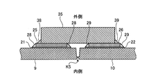
- FIG. 2 is a cross-sectional view of a temporarily joined portion that is temporarily joined by the welding method according to the first embodiment.
- FIG. 3 is a plan view of a temporarily joined portion that is temporarily joined by the welding method according to the first embodiment.
- FIG. 4 is a cross-sectional view of a temporarily joined portion that is temporarily joined by the welding method according to the second embodiment.
- the welding method according to the first embodiment is a welding method in which cylindrical members are welded to each other, and the cylindrical members are temporarily joined by a connecting plate (connecting member), and the cylindrical members are finally joined by welding in a temporarily joined state.
- a pressure vessel of a steam generator used in a pressurized water reactor is applied as an object to be welded.
- the description is applied to a pressure vessel.
- the present invention is not limited to the pressure vessel, and any member may be used as long as the cylindrical members are welded to each other.
- a pressure vessel to be welded will be described with reference to FIG.
- FIG. 1 is a front view of a pressure vessel welded by the welding method according to the first embodiment.
- the pressure vessel 1 is constituted by joining a plurality of cylindrical members, and the plurality of cylindrical members are made of low alloy steel.
- the left side in the figure is the upper side in the vertical direction
- the right side in the figure is the lower side in the vertical direction.
- the pressure vessel 1 is welded in a state where the axial direction of each cylindrical member is the horizontal direction.
- the pressure vessel 1 includes, as a plurality of cylindrical members, an upper hemispherical member 5, a first cylindrical member 6, a tapered member 7, a second cylindrical member 8, a third cylindrical member 9, a fourth cylindrical member 10, A lower hemispherical member 11 is provided.
- the cylindrical member described in the claims includes not only a cylindrical member but also a member having a cylindrical portion, and includes the upper hemispherical member 5, the tapered member 7, and the lower hemispherical member 11.
- the upper hemispherical member 5 has a cylindrical portion 5a formed on the lower side in the axial direction, and the upper side of the cylindrical portion 5a is formed in a hollow hemispherical shape. Further, the upper hemispherical member 5 is formed with an opening 5b that is open toward the outside on the upper side of the axial center thereof.
- the first cylindrical member 6 is formed in a cylindrical shape having the same diameter as the cylindrical portion 5 a of the upper hemispherical member 5.
- the first cylindrical member 6 is joined to the cylindrical portion 5 a on the upper side in the axial direction, which is the lower side of the upper hemispherical member 5.
- the pressure vessel 1 forms the groove part K1 by abutting the cylindrical part 5a of the upper hemispherical member 5 and the upper side of the first cylindrical member 6 in the axial direction, and welding the groove part K1.
- the weld M1 is formed.
- the taper member 7 is formed in a tapered shape that tapers from the upper side toward the lower side.
- the taper member 7 has an upper diameter that is the same as the lower diameter of the first cylindrical member 6, and a lower diameter that is the same as the upper diameter of the second cylindrical member 8. .
- the taper member 7 is joined to the lower side of the first cylindrical member 6 at the upper side in the axial direction. For this reason, the pressure vessel 1 is welded by forming a groove portion K2 by abutting the lower side of the first cylindrical member 6 and the upper side of the taper member 7 in the axial direction and welding the groove portion K2. Part M2 is formed.
- the second cylindrical member 8 is formed in a cylindrical shape having the same diameter as that of the lower side of the tapered member 7.
- the second cylindrical member 8 is joined to the lower side of the taper member 7 at the upper side in the axial direction. For this reason, the pressure vessel 1 is welded by forming the groove portion K3 by abutting the lower side of the taper member 7 and the upper side of the second cylindrical member 8 in the axial direction and welding the groove portion K3.
- Part M3 is formed.
- the third cylindrical member 9 is formed in a cylindrical shape having the same diameter as that of the second cylindrical member 8.
- the third cylindrical member 9 is joined to the lower side of the second cylindrical member 8 at the upper side in the axial direction.
- the pressure vessel 1 forms the groove part K4 by abutting the lower side of the second cylindrical member 8 and the upper side of the third cylindrical member 9 in the axial direction, and welding the groove part K4.
- the weld M4 is formed.
- the fourth cylindrical member 10 is formed in a cylindrical shape having the same diameter as the third cylindrical member 9.
- the fourth cylindrical member 10 is joined to the lower side of the third cylindrical member 9 on the upper side in the axial direction.
- the pressure vessel 1 forms the groove part K5 by abutting the lower side of the third cylindrical member 9 and the upper side of the fourth cylindrical member 10 in the axial direction, and welding the groove part K5.
- the weld M5 is formed.
- the lower hemispherical member 11 has a cylindrical portion 11a formed on the upper side in the axial direction, and the lower side of the cylindrical portion 11a is formed in a hollow hemispherical shape.
- the lower hemispherical member 11 is joined to the lower side of the fourth cylindrical member 10 on the upper side in the axial direction.
- the pressure vessel 1 forms a groove portion K6 by abutting the lower side of the fourth cylindrical member 10 and the upper side of the lower hemispherical member 11 in the axial direction, and welding the groove portion K6.
- a weld M6 is formed.
- the pressure vessel 1 joins the upper hemispherical member 5 and the first cylindrical member 6 at the welded part M1, joins the first cylindrical member 6 and the tapered member 7 at the welded part M2, and connects the tapered member 7 and the second cylindrical member 7 to the second.
- the cylindrical member 8 is joined at the welded part M3, the second cylindrical member 8 and the third cylindrical member 9 are joined at the welded part M4, and the third cylindrical member 9 and the fourth cylindrical member 10 are joined at the welded part M5. And it can form by joining the 4th cylindrical member 10 and the lower hemispherical member 11 in the welding part M6.
- the welds M1 to M6 are welded by the welding method of the first embodiment.
- the welding method of Example 1 is demonstrated.
- FIG. 2 is a cross-sectional view of a temporarily joined portion that is temporarily joined by the welding method according to the first embodiment.
- FIG. 3 is a plan view of a temporarily joined portion that is temporarily joined by the welding method according to the first embodiment.
- the welding method of Example 1 the case where the 3rd cylindrical member 9 and the 4th cylindrical member 10 are joined is demonstrated. Note that the welding method of the first embodiment is not limited to the joining of the third cylindrical member 9 and the fourth cylindrical member 10, but can be applied to any of the welded portions M1 to M6.
- the connecting plate 35 used in the welding method of Example 1 is made of carbon steel (second material).
- the cylindrical members 6 to 11 of the pressure vessel 1 are made of low alloy steel (first material)
- the connecting plate 35 and the cylindrical members 6 to 11 are made of different materials. ing.
- the connecting plate 35 As a characteristic of welding, when the carbon steel connecting plate 35 and the low-alloy steel cylindrical members 6 to 11 are directly joined, in order to ensure the welding quality of the cylindrical members 6 to 11 as products, that is, In order to prevent cracking of the cylindrical members 6 to 11, the connecting plate 35 needs to be preheated. At this time, when the connecting plate 35 is attached and welded in a state where the end portions of the cylindrical members 6 to 11 are axially abutted to form the groove portions K1 to K6, the cylindrical members 6 to 11 and the connecting plate 35 are attached to each other. Preheating means that the handling work of the preheating apparatus is complicated, that a large apparatus such as the pressure vessel 1 becomes a high place work, and the process of forming the groove portions K1 to K6 requires many personnel. In addition to the time required, the time until the preheating temperature is reached is a waiting time, which greatly impairs the economy and safety.
- the welding method of Example 1 in the temporary joining process, the build-up welding process, the contact plate joining process, the butting process, and the connecting plate joining process are sequentially performed.
- the build-up welding process that requires preheating, and the butting process and connection plate joining process that do not require preheating are performed separately to improve economy and safety.
- the filler metal made of low alloy steel of the same material as the third cylindrical member 9 and the fourth cylindrical member 10 is used.
- the filler metal is melted to perform build-up welding, so that the first wall is formed on the outer peripheral surface of the third cylindrical member 9 with the portion that becomes the groove portion K5 in the subsequent butting process.
- a built-up portion 21 is formed, and a second built-up portion 22 is formed on the outer peripheral surface of the fourth cylindrical member 10.
- the shape of the first build-up portion 21 and the second build-up portion 22 to be formed is a rectangular frame shape surrounded by four sides, and extends in the axial direction.
- the circumferentially central portions of the two sides are gap portions 21a and 22a that are not subjected to overlay welding. That is, the first build-up portion 21 and the second build-up portion 22 are provided with concave partial build-up portions 21b and 22b on both sides in the circumferential direction across the gap portions 21a and 22a. It is provided so that the hollow side of 22b opposes.
- a first contact plate (first interposed portion) 25 and a second contact plate (second interposed portion) 26 made of carbon steel are used, and the first contact plate 25 and the second caulking plate 26 are welded to the build-up portions 21 and 22 using a filler material made of carbon steel of the same material as the caulking plates 25 and 26.
- the size of each of the contact plates 25 and 26 is slightly larger than the inside of the four sides of each of the built-up portions 21 and 22.
- the cylindrical member 9.10 has a size that is necessary and sufficient for temporary joining.
- the first contact plate 25 is disposed on the first build-up portion 21, and the first build-up portion 21 and the first contact plate 25 are welded using a filler material of carbon steel.
- the first welded portion 28 is formed.
- the second contact plate 26 is disposed on the second build-up portion 22 and the second build-up portion 22 and the second contact plate 26 are welded using a carbon steel filler material.
- the second welded portion 29 is formed.
- the groove portion K5 is formed in the circumferential direction of the pressure vessel 1 by butting the third cylindrical member 9 and the fourth cylindrical member 10 in the axial direction. 2 and 3, the left side in the drawing is the third cylindrical member 9, and the right side in the drawing is the fourth cylindrical member 10.
- connection plate 35 made of carbon steel is used, and the connecting plate 35 is welded to the respective contact plates 25 and 26 without preheating using a filler material of carbon steel. Is done.
- the connection plate 35 has a rectangular parallelepiped block shape, and has a length that allows suspension between the first contact plate 25 and the second contact plate 26.
- the connecting plate 35 is not limited to a block shape, and may be, for example, an H steel shape as long as it has sufficient strength for temporary joining of the cylindrical members 9 and 10.
- one end portion of the connecting plate 35 is disposed on the first contact plate 25, and the first contact plate 25 and one end portion of the connecting plate 35 are joined using a carbon steel filler material.
- the third weld 38 is formed by welding without preheating.
- the other end of the connecting plate 35 is disposed on the second contact plate 26, and the other end of the second applying plate 26 and the connecting plate 35 using a carbon steel filler material. Are welded without preheating to form a fourth welded portion 39.
- the connecting plate 35 made of carbon steel is welded to the respective contact plates 25 and 26 made of carbon steel without preheating using a filler material made of carbon steel.
- the connecting plate joining step since a plurality of connecting plates 35 are joined at equal intervals in the circumferential direction of the pressure vessel 1, in the temporary joining step, the overlay welding step, the contact plate joining step, and the connecting plate joining step are connected. This is repeated as many times as the number of the plates 35 joined. Further, the number of joints of the connecting plate 35 is appropriately determined according to the diameter of the cylindrical member.
- the main joining process performed after a temporary joining process is demonstrated.
- the main joining step there are an inner peripheral surface joining step, a temporary joining removal step, and an outer peripheral surface joining step, which are generally performed in this order.
- the inner peripheral surface joining step the inner peripheral surface side of the groove portion K5 is surrounded by a filler metal made of low alloy steel in a state where the connecting plate 35 is joined to the outside of the pressure vessel 1 (temporary joined state). Welded in the direction.
- the groove portion K5 is formed using a filler material made of low alloy steel in a state where the outer connecting plate 35 of the pressure vessel 1 is removed (temporary joining release state).
- the outer peripheral surface side is welded in the circumferential direction. Note that this is an example of the main joining process, and the present invention is not limited to this.
- After removing the temporary joining member after welding a welding amount that can maintain the butt state even if the temporary joining member is removed, which is the inner circumferential surface, the outer circumferential surface, or both, or a part of each of them. Is the main point of the main joining process. Moreover, it is not necessary to remove all the temporary joining members in this step, and it is appropriately performed as long as the outer peripheral surface joining step is not hindered.
- the first and second built-up portions 21 and 22 are connected to the third and fourth cylindrical members 9 and 10 with the respective cylindrical members 9 and 10. Since overlay welding is performed using the same material, quality requirements for the cylindrical member can be satisfied. And the 1st padding part 25 and the 2nd padding board 26 are joined to the 1st buildup part 21 and the 2nd buildup part 22 via the 1st welding part 28 and the 2nd welding part 29, and further, The connection plate 35 made of carbon steel can be joined to the first and second contact plates 25 and 26 made of carbon steel without preheating.
- each cylindrical member 9 and 10 and connecting plate 35 are preheated.
- each of the contact plates 25 and 26 and the connecting plate 35 is made of carbon steel, the connecting plate 35 can be welded without preheating. There is no need to preheat in the joining process.
- the connecting plate 35 can be simply temporarily joined to the cylindrical members 9 and 10 while satisfying the quality requirements for the cylindrical members 9 and 10.
- the build-up ranges of the build-up portions 21 and 22 are A range along the outer edge may be used. For this reason, while being able to minimize the build-up range of each build-up part 21 and 22, it is economical, and the thermal influence to each cylindrical member 9 and 10 by build-up welding can be suppressed.
- the connecting plate 35 is welded to the outside of the pressure vessel 1.
- the present invention is not limited to this, and the connecting plate 35 may be welded to the inside of the pressure vessel 1.
- Each of the contact plates 25 and 26 is not limited to a flat plate, and preferably has an optimal shape according to the shape of the peripheral surface sandwiching the groove portions K1 to K6. It is preferable to have an optimum shape according to the arrangement of the contact plates 25 and 26.
- FIG. 4 is a cross-sectional view of a temporarily joined portion that is temporarily joined by the welding method according to the second embodiment.
- the welding method of Example 2 is a welding method in which the contact plates 25 and 26 of Example 1 are omitted.
- the temporary joining process in the welding method of Example 2 is demonstrated.
- the thickness of each of the built-up parts 21 and 22 is preheated for the cylindrical members 9 and 10 during welding in the connecting plate joining process. Even if it does not perform, it is the thickness which does not have a thermal influence on each cylindrical member 9 and 10.
- the thickness of each of the built-up portions 21 and 22 is determined in advance by a confirmation test. Further, when the connecting plate 35 is welded to the build-up portions 21 and 22 formed on the cylindrical members 9 and 10, when preheating is required for the build-up portions 21 and 22, the build-up welding process Then, build-up welding is performed in advance on each build-up portion 21, 22 formed on each cylindrical member 9, 10 using a filler material that does not require preheating in the connecting plate joining step. In addition, since a matching process is the same as that of Example 1, description is abbreviate
- a connecting plate 35 made of carbon steel is used, and the connecting plate 35 is welded to the respective built-up parts 21 and 22 without preheating using a filler material of carbon steel.
- the connecting plate 35 is not limited to the block shape, and may be, for example, an H steel shape as long as it has sufficient strength for temporary joining of the cylindrical members 9 and 10. .
- one end portion of the connecting plate 35 is disposed on the first build-up portion 21, and one end portion of the first build-up portion 21 and the connecting plate 35 is formed using a carbon steel filler material. Are welded without preheating to form the first welded portion 40.
- the other end of the connecting plate 35 is disposed on the second build-up portion 22, and the other of the second build-up portion 22 and the connecting plate 35 is made of a carbon steel filler material.
- the second welded portion 41 is formed by welding the end portion without preheating. At this time, each welding part 40 and 41 is welded only to the range of each build-up part 21 and 22, and is not welded to each cylindrical member 9 and 10.
- FIG. Thereby, the connection board 35 which consists of carbon steel is welded to each build-up part 21 and 22 which consists of low alloy steel without preheating using the filler material which consists of carbon steel.
- the first and second built-up portions 21 and 22 are the same as the cylindrical members 9 and 10 in the third cylindrical member 9 and the fourth cylindrical member 10. Since overlay welding is performed using a material, the quality requirement for the cylindrical member can be satisfied. Then, the connecting plate 35 is joined to the first build-up part 21 and the second build-up part 22 via the first weld part 40 and the second weld part 41. Thereby, when welding the connecting plate 35 of carbon steel and each cylindrical member 9 and 10 of low alloy steel using the filler material of low alloy steel, each cylindrical member 9 and 10 and connecting plate 35 are preheated.
- connection plate 35 can be attached and welded to each of the built-up portions 21 and 22 that do not require preheating, the connecting plate 35 can be welded without preheating, and the butting process and connecting plate joining process. No preheating is required. As described above, even in the welding method according to the second embodiment, the connection plate 35 can be simply temporarily joined to the cylindrical members 9 and 10 while satisfying the quality requirements for the cylindrical members 9 and 10.
- the welding method according to the present invention is useful when the cylindrical members are temporarily joined to each other by the connecting member, and is particularly suitable for welding the pressure vessel of the steam generator.
Landscapes
- Engineering & Computer Science (AREA)
- Mechanical Engineering (AREA)
- Butt Welding And Welding Of Specific Article (AREA)
- Arc Welding In General (AREA)
Abstract
第1材料からなる第3円筒部材9と第4円筒部材10とを軸方向に突き合わせて形成される開先部K5を挟んで、第3円筒部材9および第4円筒部材10に、第1材料からなる溶加材を用いて肉盛溶接を行うことにより、第3円筒部材9および第4円筒部材10に第1肉盛部21および第2肉盛部22を形成する肉盛溶接工程と、連結板35の一方の端部と第1肉盛部21とを、第2材料からなる第1当て板25を介して接合すると共に、連結板35の他方の端部と第2肉盛部22とを、第2材料からなる第2当て板26を介して接合することで、連結板35を第3円筒部材9および第4円筒部材10に仮接合する連結板接合工程と、を備えた。
Description
本発明は、連結部材により円筒部材同士を仮接合した状態で、円筒部材同士を溶接により本接合する溶接方法に関するものである。
従来、管と管とを突き合わせて形成される開先の溶接前に、管と管とのセンター出しを行うための管開先変形矯正用治具が知られている(例えば、特許文献1参照)。管開先変形矯正用治具は、上枠と下枠とから成る治具本体を管の外周に取り付けることで管を真円に修正し、修正した管に取り付けられた治具本体同士を連結することで、管と管とのセンター出しを行っている。
しかしながら、従来の管開先変形矯正用治具を用いる場合、開先の溶接前に、治具本体を管に取り付ける必要があるため、治具本体の取付作業が非常に煩雑となる。一方、治具を用いない方法として、開先の溶接前に、連結部材により円筒部材同士を仮接合し、この状態で、円筒部材同士を溶接により本接合する方法がある。この場合、連結部材の一端と一方の円筒部材とを溶接し、連結部材の他端と他方の円筒部材とを溶接する必要がある。このとき、円筒部材への品質要求として円筒部材を予熱する場合がある。予熱せずに溶接を行うと、円筒部材と仮設部材との溶接部において、応力による割れが発生し易くなるからである。このため、応力による割れの発生を抑制すべく、円筒部材と連結部材との溶接前に、連結部材を予熱する必要があった。
そこで、本発明は、円筒部材への品質要求を満たしつつ、連結部材により円筒部材同士を簡単に仮接合することができる溶接方法を提供することを課題とする。
本発明の溶接方法は、連結部材により第1円筒部材と第2円筒部材とを仮接合した状態で、第1円筒部材と第2円筒部材とを溶接により本接合する溶接方法であって、第1円筒部材および第2円筒部材は、溶接時において予熱が必要な第1材料で構成され、連結部材は、溶接時において予熱が不要な第2材料で構成され、第1円筒部材の端部と第2円筒部材の端部とを軸方向に突き合わせて形成される開先部を挟んで、第1円筒部材および第2円筒部材に、第1材料からなる溶加材を用いて肉盛溶接を行うことにより、第1円筒部材に第1肉盛部を形成し、第2円筒部材に第2肉盛部を形成する肉盛溶接工程と、連結部材の一方の端部と第1肉盛部とを、第2材料からなる第1介在部を介して接合すると共に、連結部材の他方の端部と第2肉盛部とを、第2材料からなる第2介在部を介して接合することで、連結部材を第1円筒部材および第2円筒部材に仮接合する連結部材接合工程と、を備えたことを特徴とする。
この構成によれば、第1円筒部材に第1肉盛部を形成し、第2円筒部材に第2肉盛部を形成することができる。これにより、各円筒部材は、円筒部材に適した溶接材料となる各肉盛部を介して連結部材と接合できるため、各円筒部材に対して、異なる材料である第2材料が溶接されることがない。また、連結部材は、同じ材料となる各介在部を介して各肉盛部と接合できるため、連結部材を予熱することなく、連結部材を各肉盛部を介して各円筒部材と仮接合することができる。以上により、円筒部材への品質要求を満たしつつ、連結部材を簡単に各円筒部材へ仮接合することができる。
この場合、第1介在部は、第1肉盛部に接合される第1当て板であり、第2介在部は、第2肉盛部に接合される第2当て板であり、肉盛溶接工程後、第1当て板と第1肉盛部とを、第2材料からなる溶加材を用いて溶接を行い、第2当て板と第2肉盛部とを、第2材料からなる溶加材を用いて溶接を行う当て板接合工程を、さらに備え、連結部材接合工程では、連結部材の一方の端部と第1当て板とを、第2材料からなる溶加材を用いて溶接を行い、連結部材の他方の端部と第2当て板とを、第2材料からなる溶加材を用いて溶接を行うことが好ましい。
この構成によれば、各当て板を各円筒部材に溶接する際に、予め円筒部材に適した溶加材で各肉盛部を形成してから、各肉盛部に各当て板を溶接により取り付ける。そして、連結部材が各当て板に溶接されるとき、連結部材である第2材料の一部が、各当て板に溶け込むことで、円筒部材である第1材料に混ざることを防いでいる。また、各当て板および各肉盛部を除去する際には、各肉盛部の肉盛範囲内で除去することで、各円筒部材を削り取ることが無い。加えて、各肉盛部に各当て板を取り付ける際に形成される溶接部は、各当て板の外縁部に沿っているので、各肉盛部の肉盛範囲を、各当て板の外縁部に沿った範囲とすることができる。これにより、各肉盛部の肉盛範囲を必要最小限にして経済的であると共に、肉盛溶接による各円筒部材への熱影響を抑制することができる。なお、各肉盛部に各当て板を溶接する溶加材は、各肉盛部および各当て板に適したものであり、予熱の要否は各肉盛部の品質要求に従っている。
この場合、第1介在部は、連結部材の一方の端部と第1肉盛部とを、第2材料からなる溶加材を用いて溶接を行うことにより形成された第1溶接部であり、第2介在部は、連結部材の他方の端部と第2肉盛部とを、第2材料からなる溶加材を用いて溶接を行うことにより形成された第2溶接部であることが好ましい。
この構成によれば、各介在部を、各当て板に代えて、各溶接部にすることで、連結部材を取り付ける場所が各肉盛部となるため、各当て板を設ける必要はなく、また、各当て板の取り付け溶接を省略することができる。これにより、各円筒部材と連結部材との接合部分を簡易な構成とすることができる。なお、各当て板に代わって取り付けられる各肉盛部は、連結部材の取り付け溶接時において、予熱不要であることが好ましい。一方で、各円筒部材の各肉盛部への連結部材の取り付け溶接時において、各肉盛部に対して予熱が必要な場合は、予め各肉盛部を予熱して、予熱が不要な肉盛溶接を、各肉盛部上に行うことが好ましい。
この場合、第1材料は、低合金鋼であり、第2材料は、炭素鋼であることが好ましい。
この構成によれば、第1材料は低合金鋼であり、第2材料は炭素鋼であるため、低合金鋼からなる各円筒部材に適した連結部材を用いることができる。
本発明の溶接方法によれば、円筒部材への品質要求を満たしつつ、連結部材を予熱することなく、連結部材を簡単に各円筒部材へ仮接合することができる。
以下、添付した図面を参照して、本発明に係る溶接方法について説明する。なお、以下の実施例によりこの発明が限定されるものではない。また、下記実施例における構成要素には、当業者が置換可能かつ容易なもの、或いは実質的に同一のものが含まれる。
実施例1に係る溶接方法は、円筒部材同士を溶接する溶接方法であり、連結板(連結部材)により円筒部材同士を仮接合し、仮接合状態で溶接により円筒部材同士を本接合している。この溶接方法は、溶接対象として、例えば、加圧水型原子炉に用いられる蒸気発生器の圧力容器が適用される。なお、実施例1では、圧力容器に適用して説明するが、圧力容器に限らず、円筒部材同士を溶接するものであれば、何れであってもよい。以下、図1を参照して、溶接対象となる圧力容器について説明する。
図1は、実施例1に係る溶接方法により溶接された圧力容器の正面図である。圧力容器1は、複数の円筒部材を接合して構成され、複数の円筒部材は低合金鋼で構成されている。圧力容器1は、図示左側が鉛直方向の上部側となり、図示右側が鉛直方向の下部側となる。なお、圧力容器1の溶接は、各円筒部材の軸方向を水平方向とした状態で行われる。
圧力容器1は、複数の円筒部材として、図示左側から順に、上部半球部材5、第1円筒部材6、テーパー部材7、第2円筒部材8、第3円筒部材9、第4円筒部材10、および下部半球部材11を有している。なお、請求項で述べる円筒部材は、円筒形状の部材だけでなく、円筒部を有する部材も含み、上記の上部半球部材5、テーパー部材7、および下部半球部材11を含んだ意である。
上部半球部材5は、軸方向の下部側に、円筒部5aが形成され、円筒部5aの上部側が中空の半球形状に形成されている。また、上部半球部材5は、その軸中心の上部側に、外側へ向けて突出するように開口された開口部5bが形成されている。
第1円筒部材6は、上部半球部材5の円筒部5aと同径の円筒形状に形成されている。この第1円筒部材6は、軸方向の上部側が、上部半球部材5の下部側である円筒部5aと接合される。このため、圧力容器1は、上部半球部材5の円筒部5aと第1円筒部材6の上部側とを、軸方向に突き合わせて開先部K1を形成し、この開先部K1を溶接することで溶接部M1が形成される。
テーパー部材7は、上部側から下部側へ向けて先細りとなるテーパー形状に形成されている。テーパー部材7は、上部側の径が第1円筒部材6の下部側の径と同径となっており、下部側の径が第2円筒部材8の上部側の径と同径となっている。このテーパー部材7は、軸方向の上部側が、第1円筒部材6の下部側と接合される。このため、圧力容器1は、第1円筒部材6の下部側とテーパー部材7の上部側とを、軸方向に突き合わせて開先部K2を形成し、この開先部K2を溶接することで溶接部M2が形成される。
第2円筒部材8は、テーパー部材7の下部側の径と同径の円筒形状に形成されている。この第2円筒部材8は、軸方向の上部側が、テーパー部材7の下部側と接合される。このため、圧力容器1は、テーパー部材7の下部側と第2円筒部材8の上部側とを、軸方向に突き合わせて開先部K3を形成し、この開先部K3を溶接することで溶接部M3が形成される。
第3円筒部材9は、第2円筒部材8の径と同径の円筒形状に形成されている。この第3円筒部材9は、軸方向の上部側が、第2円筒部材8の下部側と接合される。このため、圧力容器1は、第2円筒部材8の下部側と第3円筒部材9の上部側とを、軸方向に突き合わせて開先部K4を形成し、この開先部K4を溶接することで溶接部M4が形成される。
第4円筒部材10は、第3円筒部材9の径と同径の円筒形状に形成されている。この第4円筒部材10は、軸方向の上部側が、第3円筒部材9の下部側と接合される。このため、圧力容器1は、第3円筒部材9の下部側と第4円筒部材10の上部側とを、軸方向に突き合わせて開先部K5を形成し、この開先部K5を溶接することで溶接部M5が形成される。
下部半球部材11は、軸方向の上部側に、円筒部11aが形成され、円筒部11aの下部側が中空の半球形状に形成されている。この下部半球部材11は、軸方向の上部側が、第4円筒部材10の下部側と接合される。このため、圧力容器1は、第4円筒部材10の下部側と下部半球部材11の上部側とを、軸方向に突き合わせて開先部K6を形成し、この開先部K6を溶接することで溶接部M6が形成される。
よって、圧力容器1は、上部半球部材5と第1円筒部材6とを溶接部M1において接合し、第1円筒部材6とテーパー部材7とを溶接部M2において接合し、テーパー部材7と第2円筒部材8とを溶接部M3において接合し、第2円筒部材8と第3円筒部材9とを溶接部M4において接合し、第3円筒部材9と第4円筒部材10とを溶接部M5において接合し、第4円筒部材10と下部半球部材11とを溶接部M6において接合することで、形成できる。ここで、溶接部M1~M6は、実施例1の溶接方法によって溶接されている。以下、図2および図3を参照して、実施例1の溶接方法について説明する。
図2は、実施例1に係る溶接方法により仮接合された仮接合部分の断面図である。図3は、実施例1に係る溶接方法により仮接合された仮接合部分の平面図である。実施例1の溶接方法では、第3円筒部材9と第4円筒部材10とを接合する場合について説明する。なお、実施例1の溶接方法は、第3円筒部材9と第4円筒部材10との接合に限らず、溶接部M1~M6のいずれにも適用可能である。
実施例1の溶接方法では、第3円筒部材9と第4円筒部材10とを接合する場合、大別して、第3円筒部材9および第4円筒部材10を連結板35を用いて仮接合する仮接合工程と、第3円筒部材9および第4円筒部材10を本接合する本接合工程とが行われる。
ここで、実施例1の溶接方法に用いられる連結板35は、炭素鋼(第2材料)で構成されている。上記したように、圧力容器1の各円筒部材6~11は、低合金鋼(第1材料)で構成されているため、連結板35と、各円筒部材6~11とは、異なる材料となっている。
溶接の特性として、炭素鋼の連結板35と、低合金鋼の各円筒部材6~11とを直接接合する場合、製品である各円筒部材6~11の溶接品質を確保するために、すなわち、各円筒部材6~11の割れを防ぐために、連結板35の予熱を行う必要がある。このとき、各円筒部材6~11の端部を軸方向に突き合わせて開先部K1~K6を形成した状態で、連結板35を取り付け溶接する場合、各円筒部材6~11および連結板35を予熱することは、予熱器具の取り扱い作業が煩雑であること、圧力容器1のような大型機器では高所作業となってしまうこと、開先部K1~K6を形成する工程には多くの人員と時間を要するものである上に予熱温度に到達するまでの時間が待ち時間となること、から経済性・安全性を大きく損なうものである。
そこで、実施例1の溶接方法において、仮接合工程では、肉盛溶接工程と、当て板接合工程と、突き合わせ工程と、連結板接合工程とが順に行われている。そして、予熱が必要な肉盛溶接工程と、予熱が不要な突き合わせ工程および連結板接合工程とを切り離して行うことで経済性・安全性を向上させている。
肉盛溶接工程では、第3円筒部材9および第4円筒部材10と同じ材料の低合金鋼からなる溶加材が用いられる。肉盛溶接工程では、溶加材を溶融させて肉盛溶接を行うことで、後の突き合わせ工程にて開先部K5となる部位を挟んで、第3円筒部材9の外周面に第1肉盛部21を形成し、第4円筒部材10の外周面に第2肉盛部22を形成する。このとき、図3に示すように、形成される第1肉盛部21および第2肉盛部22の形状は、四辺で囲まれた方形の枠状となっており、軸方向に延在する二辺の周方向中央の部分は、肉盛溶接がされていない間隙部21a,22aとなっている。つまり、第1肉盛部21および第2肉盛部22は、間隙部21a,22aを挟んで、周方向の両側に凹状の部分肉盛部21b,22bが設けられ、部分肉盛部21b,22bの窪み側が対向するように設けられている。
肉盛溶接工程後に行われる当て板接合工程では、炭素鋼で構成された第1当て板(第1介在部)25および第2当て板(第2介在部)26が用いられ、第1当て板25および第2当て板26は、各当て板25,26と同じ材料の炭素鋼からなる溶加材を用いて、各肉盛部21,22に溶接される。各当て板25,26の大きさは、各肉盛部21,22の四辺の枠の内側よりも、僅かに大きいものとなっている。また、各肉盛部21、22および各当て板25、26の大きさ、ならびに各当て板25、26を各肉盛部21、22に溶接したときに形成される溶接部の大きさは、各円筒部材9.10の仮接合に必要十分な強度となる大きさとなっている。
具体的に、当て板接合工程では、第1肉盛部21に第1当て板25を配置し、炭素鋼の溶加材を用いて第1肉盛部21と第1当て板25とを溶接することにより、第1溶接部28を形成する。また、当て板接合工程では、第2肉盛部22に第2当て板26を配置し、炭素鋼の溶加材を用いて第2肉盛部22と第2当て板26とを溶接することにより、第2溶接部29を形成する。これにより、炭素鋼からなる各当て板25,26は、炭素鋼からなる溶加材を用いて、低合金鋼からなる各肉盛部21,22へ溶接される。このとき、各溶接部28,29は、各肉盛部21,22の範囲だけに溶接され、各円筒部材9,10に溶接されない。
当て板接合工程後に行われる突き合わせ工程では、第3円筒部材9と第4円筒部材10とを軸方向に突き合わせることで、圧力容器1の周方向に開先部K5を形成する。なお、図2および図3において、図示左側が第3円筒部材9であり、図示右側が第4円筒部材10である。
突き合わせ工程後に行われる連結板接合工程では、炭素鋼で構成された連結板35が用いられ、連結板35は、炭素鋼の溶加材を用いて、各当て板25,26に予熱無しで溶接される。連結板35は、その形状が長方体のブロック形状となっており、第1当て板25と第2当て板26との間を懸架可能な長さとなっている。なお、連結板35は、ブロック形状に限らず、各円筒部材9,10の仮接合に必要な強度に十分なものであれば、例えば、H鋼形状であってもよい。
連結板接合工程では、第1当て板25に連結板35の一方の端部を配置し、炭素鋼の溶加材を用いて、第1当て板25と連結板35の一方の端部とを予熱無しで溶接することにより、第3溶接部38を形成する。また、連結板接合工程では、第2当て板26に連結板35の他方の端部を配置し、炭素鋼の溶加材を用いて、第2当て板26と連結板35の他方の端部とを予熱無しで溶接することにより、第4溶接部39を形成する。これにより、炭素鋼からなる連結板35は、炭素鋼からなる溶加材を用いて、炭素鋼からなる各当て板25,26へ予熱無しで溶接される。
なお、連結板35は、圧力容器1の周方向において、等間隔に複数接合されることから、上記の仮接合工程では、肉盛溶接工程、当て板接合工程、および連結板接合工程が、連結板35の接合数だけ、繰り返し行われる。また、連結板35の接合数は、円筒部材の径に応じて適宜決められる。
続いて、仮接合工程後に行われる本接合工程について説明する。本接合工程では、内周面接合工程と、仮接合除去工程と、外周面接合工程とがあり、一般的にはこの順序で行われる。内周面接合工程では、圧力容器1の外側に連結板35が接合された状態(仮接合状態)で、低合金鋼からなる溶加材を用いて、開先部K5の内周面側が周方向に溶接される。内周面接合工程後、仮接合除去工程では、連結板35と、第1当て板25および第2当て板26と、第1肉盛部21および第2肉盛部22とからなる仮接合部材が除去される。仮接合除去工程後、外周面接合工程では、圧力容器1の外側の連結板35が除去された状態(仮接合解除状態)で、低合金鋼からなる溶加材を用いて、開先部K5の外周面側が周方向に溶接される。なお、これは本接合工程の一例を示したものであり、これに限ることは無い。内周面または外周面、またはその両方、あるいはそれぞれの一部であって、仮接合部材を除去しても突き合わせ状態を維持できるだけの溶接量を溶接してから、仮接合部材の除去を行うことが本接合工程の要点である。また、仮接合部材の除去は本工程で全てを除去する必要は無く、外周面接合工程に支障の無い範囲で適宜行われる。
以上のように、実施例1の溶接方法によれば、第3円筒部材9および第4円筒部材10に、第1肉盛部21および第2肉盛部22を、各円筒部材9,10と同じ材料を用いて肉盛溶接するため、円筒部材への品質要求を満たすことができる。そして、第1肉盛部21および第2肉盛部22には、第1当て板25および第2当て板26が、第1溶接部28および第2溶接部29を介して接合され、さらに、炭素鋼からなる第1当て板25および第2当て板26に、炭素鋼からなる連結板35を予熱無しで接合できる。これにより、炭素鋼の連結板35と低合金鋼の各円筒部材9,10とを、低合金鋼の溶加材を用いて溶接する場合は、各円筒部材9,10および連結板35を予熱しなければならなかったが、各当て板25,26および連結板35が炭素鋼であるため、連結板35を予熱することなく溶接することができ、仮接合工程のうち、突き合わせ工程および連結板接合工程において予熱を行う必要はない。以上により、実施例1の溶接方法では、各円筒部材9,10への品質要求を満たしつつ、連結板35を簡単に各円筒部材9,10へ仮接合することができる。
また、連結板35と各肉盛部21,22との間に、各当て板25,26を介在させることで、各肉盛部21,22の肉盛範囲は、各当て板25,26の外縁部に沿った範囲とすればよい。このため、各肉盛部21,22の肉盛範囲を必要最小限にして経済的であると共に、肉盛溶接による各円筒部材9,10への熱影響を抑制することができる。
なお、仮接合工程では、圧力容器1の外側に連結板35を溶接したが、これに限らず、圧力容器1の内側に連結板35を溶接してもよい。この場合、本接合工程では、内周面接合工程と、外周面接合工程との順序を入れ替えることが好ましい。また、各当て板25,26は、平板に限定されず、開先部K1~K6を挟んだ周面の形状に応じて最適な形状とすることが好ましく、同様に、連結板35も、各当て板25,26の配置に応じて最適な形状とすることが好ましい。
続いて、図4を参照して、実施例2に係る溶接方法について説明する。なお、重複した記載を避けるべく、異なる部分についてのみ説明する。図4は、実施例2に係る溶接方法により仮接合された仮接合部分の断面図である。実施例2の溶接方法は、実施例1の当て板25,26を省いた溶接方法となっている。以下、実施例2の溶接方法における仮接合工程について説明する。
仮接合工程では、肉盛溶接工程と、突き合わせ工程と、連結板接合工程とが順に行われている。ここで、肉盛溶接工程では、実施例1の構成に加えて、形成される各肉盛部21,22の厚さが、連結板接合工程における溶接時において、各円筒部材9,10の予熱を行わなくても、各円筒部材9,10に熱影響のない厚さとなっている。このとき、各肉盛部21,22の厚さは、連結板溶接工程における溶接方法よって異なる。具体的に、被覆アーク溶接などの溶接入熱の比較的少ない溶接方法である場合、各肉盛部21,22の厚さは、3mm以上あればよい。一方で、マグ溶接などの溶接入熱の比較的大きい溶接方法である場合、各肉盛部21,22の厚さは、予め確認試験にて定められる。また、各円筒部材9,10に形成された各肉盛部21,22に連結板35を溶接する際に、各肉盛部21,22に対して予熱が必要な場合は、肉盛溶接工程において、各円筒部材9,10に形成された各肉盛部21,22上に、連結板接合工程において予熱が不要となる溶加材を用いて予め肉盛溶接を行う。なお、突き合わせ工程は、実施例1と同様であるため、説明を省略する。
連結板接合工程では、炭素鋼で構成された連結板35が用いられ、連結板35は、炭素鋼の溶加材を用いて、各肉盛部21,22に予熱無しで溶接される。なお、実施例2においても、連結板35は、ブロック形状に限らず、各円筒部材9,10の仮接合に必要な強度に十分なものであれば、例えば、H鋼形状であってもよい。連結板接合工程では、第1肉盛部21に連結板35の一方の端部を配置し、炭素鋼の溶加材を用いて、第1肉盛部21と連結板35の一方の端部とを予熱無しで溶接することにより、第1溶接部40を形成する。また、連結板接合工程では、第2肉盛部22に連結板35の他方の端部を配置し、炭素鋼の溶加材を用いて、第2肉盛部22と連結板35の他方の端部とを予熱無しで溶接することにより、第2溶接部41を形成する。このとき、各溶接部40,41は、各肉盛部21,22の範囲だけに溶接され、各円筒部材9,10に溶接されない。これにより、炭素鋼からなる連結板35は、炭素鋼からなる溶加材を用いて、低合金鋼からなる各肉盛部21,22へ予熱無しで溶接される。
以上のように、実施例2の溶接方法においても、第3円筒部材9および第4円筒部材10に、第1肉盛部21および第2肉盛部22を、各円筒部材9,10と同じ材料を用いて肉盛溶接するため、円筒部材への品質要求を満たすことができる。そして、第1肉盛部21および第2肉盛部22には、連結板35が、第1溶接部40および第2溶接部41を介して接合される。これにより、炭素鋼の連結板35と低合金鋼の各円筒部材9,10とを、低合金鋼の溶加材を用いて溶接する場合は、各円筒部材9,10および連結板35を予熱しなければならなかったが、予熱が不要な各肉盛部21、22に連結板35を取付け溶接できるため、連結板35を予熱することなく溶接することができ、突き合わせ工程および連結板接合工程において予熱が不要となる。以上により、実施例2の溶接方法でも、各円筒部材9,10への品質要求を満たしつつ、連結板35を簡単に各円筒部材9,10へ仮接合することができる。
以上のように、本発明に係る溶接方法は、連結部材により円筒部材同士を仮接合する場合において有用であり、特に、蒸気発生器の圧力容器を溶接する場合に適している。
1 圧力容器
5 上部半球部材
6 第1円筒部材
7 テーパー部材
8 第2円筒部材
9 第3円筒部材
10 第4円筒部材
11 下部半球部材
21 第1肉盛部
22 第2肉盛部
25 第1当て板
26 第2当て板
28 第1溶接部
29 第2溶接部
35 連結板
40 第1溶接部
41 第2溶接部
K1~K6 開先部
M1~M6 溶接部
5 上部半球部材
6 第1円筒部材
7 テーパー部材
8 第2円筒部材
9 第3円筒部材
10 第4円筒部材
11 下部半球部材
21 第1肉盛部
22 第2肉盛部
25 第1当て板
26 第2当て板
28 第1溶接部
29 第2溶接部
35 連結板
40 第1溶接部
41 第2溶接部
K1~K6 開先部
M1~M6 溶接部
Claims (4)
- 連結部材により第1円筒部材と第2円筒部材とを仮接合した状態で、前記第1円筒部材と前記第2円筒部材とを溶接により本接合する溶接方法であって、
前記第1円筒部材および前記第2円筒部材は、溶接時において予熱が必要な第1材料で構成され、前記連結部材は、溶接時において予熱が不要な第2材料で構成され、
前記第1円筒部材の端部と前記第2円筒部材の端部とを軸方向に突き合わせて形成される開先部を挟んで、前記第1円筒部材および前記第2円筒部材に、前記第1材料からなる溶加材を用いて肉盛溶接を行うことにより、前記第1円筒部材に第1肉盛部を形成し、前記第2円筒部材に第2肉盛部を形成する肉盛溶接工程と、
前記連結部材の一方の端部と前記第1肉盛部とを、前記第2材料からなる第1介在部を介して接合すると共に、前記連結部材の他方の端部と前記第2肉盛部とを、前記第2材料からなる第2介在部を介して接合することで、前記連結部材を前記第1円筒部材および前記第2円筒部材に仮接合する連結部材接合工程と、を備えたことを特徴とする溶接方法。 - 前記第1介在部は、前記第1肉盛部に接合される第1当て板であり、前記第2介在部は、前記第2肉盛部に接合される第2当て板であり、
肉盛溶接工程後、前記第1当て板と前記第1肉盛部とを、前記第2材料からなる溶加材を用いて溶接を行い、前記第2当て板と前記第2肉盛部とを、前記第2材料からなる溶加材を用いて溶接を行う当て板接合工程を、さらに備え、
前記連結部材接合工程では、前記連結部材の一方の端部と前記第1当て板とを、前記第2材料からなる溶加材を用いて溶接を行い、前記連結部材の他方の端部と前記第2当て板とを、前記第2材料からなる溶加材を用いて溶接を行うことを特徴とする請求項1に記載の溶接方法。 - 前記第1介在部は、前記連結部材の一方の端部と前記第1肉盛部とを、前記第2材料からなる溶加材を用いて溶接を行うことにより形成された第1溶接部であり、前記第2介在部は、前記連結部材の他方の端部と前記第2肉盛部とを、前記第2材料からなる溶加材を用いて溶接を行うことにより形成された第2溶接部であることを特徴とする請求項1に記載の溶接方法。
- 前記第1材料は、低合金鋼であり、前記第2材料は、炭素鋼であることを特徴とする請求項1ないし3のいずれか1項に記載の溶接方法。
Applications Claiming Priority (2)
| Application Number | Priority Date | Filing Date | Title |
|---|---|---|---|
| JP2011025285A JP5762032B2 (ja) | 2011-02-08 | 2011-02-08 | 溶接方法 |
| JP2011-025285 | 2011-02-08 |
Publications (1)
| Publication Number | Publication Date |
|---|---|
| WO2012108442A1 true WO2012108442A1 (ja) | 2012-08-16 |
Family
ID=46638655
Family Applications (1)
| Application Number | Title | Priority Date | Filing Date |
|---|---|---|---|
| PCT/JP2012/052780 Ceased WO2012108442A1 (ja) | 2011-02-08 | 2012-02-07 | 溶接方法 |
Country Status (2)
| Country | Link |
|---|---|
| JP (1) | JP5762032B2 (ja) |
| WO (1) | WO2012108442A1 (ja) |
Cited By (1)
| Publication number | Priority date | Publication date | Assignee | Title |
|---|---|---|---|---|
| WO2021081661A1 (en) * | 2019-10-31 | 2021-05-06 | Her Majesty The Queen In Right Of Canada As Represented By The Minister Of Natural Resources Canada | Hybrid butt-lap joint, and method of production |
Citations (3)
| Publication number | Priority date | Publication date | Assignee | Title |
|---|---|---|---|---|
| JPS5499747A (en) * | 1978-01-25 | 1979-08-06 | Hitachi Ltd | Reinforcing method for welded joint or stainless steel pipe and construction of welded join of stainless steel pipe |
| JPS62165068A (ja) * | 1986-01-14 | 1987-07-21 | Mitsubishi Heavy Ind Ltd | 圧力容器の外部金物取付方法 |
| JPH06328245A (ja) * | 1993-05-21 | 1994-11-29 | Mitsubishi Heavy Ind Ltd | 柱材の自動溶接方法 |
-
2011
- 2011-02-08 JP JP2011025285A patent/JP5762032B2/ja active Active
-
2012
- 2012-02-07 WO PCT/JP2012/052780 patent/WO2012108442A1/ja not_active Ceased
Patent Citations (3)
| Publication number | Priority date | Publication date | Assignee | Title |
|---|---|---|---|---|
| JPS5499747A (en) * | 1978-01-25 | 1979-08-06 | Hitachi Ltd | Reinforcing method for welded joint or stainless steel pipe and construction of welded join of stainless steel pipe |
| JPS62165068A (ja) * | 1986-01-14 | 1987-07-21 | Mitsubishi Heavy Ind Ltd | 圧力容器の外部金物取付方法 |
| JPH06328245A (ja) * | 1993-05-21 | 1994-11-29 | Mitsubishi Heavy Ind Ltd | 柱材の自動溶接方法 |
Cited By (1)
| Publication number | Priority date | Publication date | Assignee | Title |
|---|---|---|---|---|
| WO2021081661A1 (en) * | 2019-10-31 | 2021-05-06 | Her Majesty The Queen In Right Of Canada As Represented By The Minister Of Natural Resources Canada | Hybrid butt-lap joint, and method of production |
Also Published As
| Publication number | Publication date |
|---|---|
| JP2012161826A (ja) | 2012-08-30 |
| JP5762032B2 (ja) | 2015-08-12 |
Similar Documents
| Publication | Publication Date | Title |
|---|---|---|
| JP5650358B1 (ja) | 板曲げ中空ロールの製造方法並びに板曲げ中空ロールおよび鋼板製造プロセス装置 | |
| CN110421238B (zh) | 一种高强度筒体对接焊的焊接工艺 | |
| JP5658420B1 (ja) | 板曲げ中空ロールの製造方法および鋼板製造プロセス装置の製造方法 | |
| CN116551230B (zh) | 一种大尺寸钛合金薄壁锥形构件的精密装配焊接方法 | |
| CN104400211A (zh) | 一种贮箱搅拌摩擦焊缺陷等强固相补焊的方法及装置 | |
| JPH05237655A (ja) | ロータの修理方法 | |
| US6754956B1 (en) | Methods for manufacturing a nozzle box assembly for a steam turbine | |
| CN113634937A (zh) | 一种制动盘分块和拼焊方法 | |
| JP5762032B2 (ja) | 溶接方法 | |
| JP2009072795A (ja) | 溶接治具 | |
| CN105364413A (zh) | 一种筒体构件的制造方法 | |
| US8536479B2 (en) | Method for welding shafts on vertical rotational axis | |
| JP2016075586A5 (ja) | ||
| CN211638744U (zh) | 压力容器用铬钼钢与低碳钢的连接结构 | |
| WO2009006671A1 (en) | Method of forming a tank | |
| CN102744501B (zh) | 一种制造沥青搅拌设备的方法 | |
| CN110480253B (zh) | 链轮盘修复方法 | |
| CN107900544B (zh) | 一种十字焊缝不开过焊孔的焊接方法 | |
| JP2005262292A (ja) | 薄板円筒管の溶接装置 | |
| KR20190135480A (ko) | 파이프 라인의 핫탭 피팅의 왜곡 제어 및 용접 후 열처리 없는 두껍고 긴 심의 용접 시스템 및 방법 | |
| CN114952053A (zh) | 一种集箱及管座的焊接方法 | |
| CN105750752B (zh) | 一种防止炼钢转炉耳轴隔板结构裂纹的方法 | |
| JP2012245555A (ja) | 工業用ロール及びその製造方法 | |
| KR102521687B1 (ko) | 아웃트링 용접부 금속조직 모재동질화 처리방법 | |
| JP5836160B2 (ja) | 胴部接合方法および胴部 |
Legal Events
| Date | Code | Title | Description |
|---|---|---|---|
| 121 | Ep: the epo has been informed by wipo that ep was designated in this application |
Ref document number: 12744657 Country of ref document: EP Kind code of ref document: A1 |
|
| NENP | Non-entry into the national phase |
Ref country code: DE |
|
| 122 | Ep: pct application non-entry in european phase |
Ref document number: 12744657 Country of ref document: EP Kind code of ref document: A1 |