WO2012108318A1 - 映像表示スクリーンおよびこれを備えた映像表示システム - Google Patents
映像表示スクリーンおよびこれを備えた映像表示システム Download PDFInfo
- Publication number
- WO2012108318A1 WO2012108318A1 PCT/JP2012/052264 JP2012052264W WO2012108318A1 WO 2012108318 A1 WO2012108318 A1 WO 2012108318A1 JP 2012052264 W JP2012052264 W JP 2012052264W WO 2012108318 A1 WO2012108318 A1 WO 2012108318A1
- Authority
- WO
- WIPO (PCT)
- Prior art keywords
- infrared
- image
- unit
- video display
- light
- Prior art date
- Legal status (The legal status is an assumption and is not a legal conclusion. Google has not performed a legal analysis and makes no representation as to the accuracy of the status listed.)
- Ceased
Links
Images







Classifications
-
- H—ELECTRICITY
- H04—ELECTRIC COMMUNICATION TECHNIQUE
- H04N—PICTORIAL COMMUNICATION, e.g. TELEVISION
- H04N9/00—Details of colour television systems
- H04N9/12—Picture reproducers
- H04N9/31—Projection devices for colour picture display, e.g. using electronic spatial light modulators [ESLM]
- H04N9/3191—Testing thereof
- H04N9/3194—Testing thereof including sensor feedback
-
- G—PHYSICS
- G03—PHOTOGRAPHY; CINEMATOGRAPHY; ANALOGOUS TECHNIQUES USING WAVES OTHER THAN OPTICAL WAVES; ELECTROGRAPHY; HOLOGRAPHY
- G03B—APPARATUS OR ARRANGEMENTS FOR TAKING PHOTOGRAPHS OR FOR PROJECTING OR VIEWING THEM; APPARATUS OR ARRANGEMENTS EMPLOYING ANALOGOUS TECHNIQUES USING WAVES OTHER THAN OPTICAL WAVES; ACCESSORIES THEREFOR
- G03B21/00—Projectors or projection-type viewers; Accessories therefor
- G03B21/14—Details
- G03B21/26—Projecting separately subsidiary matter simultaneously with main image
-
- G—PHYSICS
- G03—PHOTOGRAPHY; CINEMATOGRAPHY; ANALOGOUS TECHNIQUES USING WAVES OTHER THAN OPTICAL WAVES; ELECTROGRAPHY; HOLOGRAPHY
- G03B—APPARATUS OR ARRANGEMENTS FOR TAKING PHOTOGRAPHS OR FOR PROJECTING OR VIEWING THEM; APPARATUS OR ARRANGEMENTS EMPLOYING ANALOGOUS TECHNIQUES USING WAVES OTHER THAN OPTICAL WAVES; ACCESSORIES THEREFOR
- G03B21/00—Projectors or projection-type viewers; Accessories therefor
- G03B21/54—Accessories
- G03B21/56—Projection screens
-
- H—ELECTRICITY
- H04—ELECTRIC COMMUNICATION TECHNIQUE
- H04N—PICTORIAL COMMUNICATION, e.g. TELEVISION
- H04N5/00—Details of television systems
- H04N5/76—Television signal recording
- H04N5/91—Television signal processing therefor
- H04N5/913—Television signal processing therefor for scrambling ; for copy protection
-
- H—ELECTRICITY
- H04—ELECTRIC COMMUNICATION TECHNIQUE
- H04N—PICTORIAL COMMUNICATION, e.g. TELEVISION
- H04N9/00—Details of colour television systems
- H04N9/12—Picture reproducers
- H04N9/31—Projection devices for colour picture display, e.g. using electronic spatial light modulators [ESLM]
- H04N9/3179—Video signal processing therefor
-
- H—ELECTRICITY
- H04—ELECTRIC COMMUNICATION TECHNIQUE
- H04N—PICTORIAL COMMUNICATION, e.g. TELEVISION
- H04N5/00—Details of television systems
- H04N5/76—Television signal recording
- H04N5/91—Television signal processing therefor
- H04N5/913—Television signal processing therefor for scrambling ; for copy protection
- H04N2005/91392—Television signal processing therefor for scrambling ; for copy protection using means for preventing making copies of projected video images
Definitions
- the present invention relates to a technique for preventing an act of re-shooting image content such as a movie displayed on a screen or an image display panel with an image recording apparatus such as a video camera.
- photographing devices such as digital image display devices and digital cameras have been widely used and high image quality has been promoted, and it has become possible to view high-quality content at low cost.
- photographing content such as images and moving images displayed on a screen or display with a photographing device such as a digital video camera and distributing the photographed content illegally (re-photographing act).
- the distribution of pirated DVDs illegally photographed in this way is against copyright protection, and the economic loss is very large, so countermeasures are urgently required.
- the facility ID (information of the facility being screened) and the device ID (information of the device being screened) are added to the image content (original image content) before display by using a digital watermark (watermark).
- a method for identifying a facility or device in which re-imaging has been performed by detecting the ID from the image content that has been embedded, re-photographed, and distributed (image content that has been re-captured).
- infrared rays are not recognized by human eyes, but are detected in the same manner as visible light in a content recording apparatus (specifically, for example, a video camera) including a CCD, a CMOS image sensor, or the like. This utilizes the difference between human visual characteristics and camera imaging characteristics.
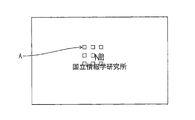
- FIG. 4A shows an example of an image obtained when an image is displayed with a camera when infrared rays are irradiated from the screen to the spectator seat together with the image display.
- the image captured by the camera includes infrared interference image A as white.
- the recaptured video can be deteriorated and the use value of the recaptured image can be eliminated, it is an effective method as a means for preventing voyeurism in a movie theater or the like. it is conceivable that.
- FIG. 4B shows an example of an image obtained when an image including infrared rays as a disturbing image is taken with a camera to which an infrared ray removal filter is attached. As shown in this figure, the interference image by infrared rays is removed by the action of the infrared ray removing filter, and the photographed image keeps the value as the content.
- the present invention has been made in view of the above problems, and an object of the present invention is to provide a technique for reliably detecting a person who removes the invisible light from an image including the invisible light and re-photographs it. To do.
- an image display screen disclosed below includes an image display unit that displays an image, an infrared light emitting unit that irradiates an observer with infrared rays together with the image, and an imaging device that the observer has An infrared detection unit that detects infrared rays reflected from the infrared ray detection unit, and the infrared light emission unit and the infrared detection unit are provided on a back surface of the video display unit, and the back surface of the infrared detection unit and the video display unit.
- the light-shielding detection part cover member which covers the clearance gap is further provided.
- Infrared rays are not recognized by human eyes, but are detected in the same manner as visible light in a photographing device (specifically, for example, a video camera) equipped with a CCD, a CMOS image sensor, or the like.
- infrared rays that are not recognized by human eyes but are recorded as a visible image on a video camera or the like during the period in which the video is displayed on the video display unit At the same time, the observer can be irradiated.
- infrared rays are added to the captured image content as an image (a re-shooting prevention signal) that interferes with the original video.
- the display quality of the retaken image can be deteriorated. Note that since infrared rays cannot be seen by human eyes, it seems to the observer that only the original video is displayed on the video display unit.
- the infrared rays reflected from the imaging device of the observer can be detected by the infrared detector.
- a light-shielding detection unit cover member is provided so as to cover a gap between the infrared detection unit and the back surface of the video display unit.
- the above configuration it is possible to degrade the display quality of the video re-captured by the imaging device possessed by the observer without degrading the display quality of the video. Furthermore, when the observer tries to re-image while removing infrared rays irradiated from the video display screen, the infrared rays reflected from the imaging device of the observer can be detected easily and accurately. Therefore, the effect of suppressing the re-shooting action can be obtained.
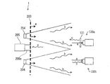
- FIG. 1 is a schematic diagram showing a schematic configuration of a video display system for preventing voyeurism according to an embodiment of the present invention.
- FIG. 2 is a schematic diagram for explaining a method for adding a disturbing image to a voyeur camera and a method for detecting the voyeur camera in the system shown in FIG.
- FIG. 3 is a block diagram showing a functional configuration of the video display system for preventing voyeurism according to the embodiment of the present invention.
- FIG. 4A is a schematic diagram illustrating an example of an image obtained when an image is displayed with a camera when infrared rays are emitted from a screen to a spectator seat together with image display.
- FIG. 4A is a schematic diagram illustrating an example of an image obtained when an image is displayed with a camera when infrared rays are emitted from a screen to a spectator seat together with image display.
- FIG. 4B is a schematic diagram illustrating an example of an image obtained when an image in which infrared rays are included as a disturbing image is captured by a camera to which an infrared removing filter is attached.
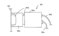
- FIG. 5 is a partially cutaway side view showing an example of the configuration of the infrared camera.
- FIG. 6 is a cross-sectional view showing an example of the configuration of the infrared camera.
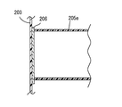
- FIG. 7 is a cross-sectional view showing an example of the configuration of the infrared camera.
- FIG. 8A is a cross-sectional view schematically showing a state in which infrared leakage occurs in the configuration of the infrared camera shown in FIG. FIG.
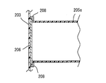
- FIG. 8B is a cross-sectional view illustrating an example of the configuration of the infrared camera.
- FIG. 9 is a side view showing an example of the configuration of the infrared camera.
- FIG. 10 is a block diagram illustrating a functional configuration of the image processing unit provided in the infrared detection unit in the video display system for preventing voyeurism according to the embodiment of the present invention.
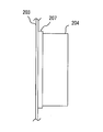
- FIG. 11 is a side view showing an example of the configuration of the infrared light emitting unit.
- an image display screen includes an image display unit that displays an image, an infrared light emitting unit that irradiates an observer with infrared rays together with the image, and the observer
- An infrared detection unit that detects infrared rays reflected from the imaging device, and the infrared light emission unit and the infrared detection unit are provided on a back surface of the video display unit, and the infrared detection unit and the video
- a light-shielding detection unit cover member that covers a gap with the back surface of the display unit is further provided (first configuration).
- the voyeur when a voyeur is attempted in a theater equipped with a video display screen in which non-visible light (infrared rays) that interfere with the video is irradiated to the viewer, the voyeur It is assumed that an infrared reflection filter or an infrared absorption filter is provided on the front surface of the camera in order to remove infrared rays (re-shooting prevention signal) for disturbing the image. Since the infrared reflection filter or the infrared absorption filter reflects infrared rays, the infrared detection unit detects the reflected light from the photographing device for voyeurism with a relatively strong intensity. Therefore, the presence of the imaging device can be easily confirmed by providing the infrared detection unit. Note that the light source of the infrared light emitting unit may be a light source provided separately from the light source that emits the re-shooting prevention signal.
- the display quality of the video recaptured by the imaging device possessed by the observer is deteriorated without degrading the display quality of the video displayed on the video display unit. Can do. Furthermore, when the observer attempts to re-photograph using a filter or the like that removes invisible light (infrared rays) irradiated from the video display screen, the infrared rays reflected from the imaging device of the observer by the infrared detection unit Can be easily detected. Therefore, it is possible to further improve the effect of preventing the re-shooting action.
- the infrared light emitting unit and the infrared detection unit are provided on a back surface of the video display unit, and cover a gap between the infrared detection unit and the back surface of the video display unit.
- a light-shielding detection unit cover member is further provided.
- this detection unit cover member By providing this detection unit cover member, it is possible to prevent the components that have become stray light due to diffraction out of the infrared rays emitted from the infrared light emission unit from entering the infrared detection unit. As a result, it is possible to detect the infrared rays reflected from the imaging device of the observer more accurately in the infrared detection unit.
- a distortion preventing member for preventing distortion of the video display unit is further provided between the detection unit cover member and the video display unit (second configuration).
- the strain preventing member for example, a configuration including a translucent resin plate (third configuration) or a configuration using a flexible material (fourth configuration) is preferable.
- the distortion preventing member when the detection unit cover member is pressed against the video display unit, the stress from the detection unit cover member is blocked or absorbed, and the display surface of the video display unit is distorted. Is prevented. Accordingly, the detection unit cover member and the video display unit can be brought into close contact with each other without affecting the display of the video display unit.
- a configuration further including a light-shielding light emitting unit cover member that covers a gap between the infrared light emitting unit and the back surface of the video display unit is also preferable (fifth configuration).
- this configuration it is possible to prevent the infrared light that should be emitted toward the front surface of the video display unit from leaking from the gap between the infrared light emitting unit and the back surface of the video display unit and becoming stray light. Thereby, the influence of stray light can be more effectively removed, and the infrared rays reflected from the imaging device of the observer can be detected more accurately by the infrared detection unit.
- a configuration in which a distortion preventing member for preventing distortion of the video display unit is further provided between the light emitting unit cover member and the video display unit (sixth configuration).
- the strain preventing member for example, a configuration including a translucent resin plate (seventh configuration) or a configuration using a flexible material (eighth configuration) is preferable.
- the sixth to eighth configurations similarly to the second to fourth configurations, by providing the distortion preventing member, when the light emitting unit cover member is pressed against the video display unit, the light emitting unit cover is provided. The stress from the member is blocked or absorbed, and the display surface of the image display unit is prevented from being distorted. Accordingly, the light emitting unit cover member and the video display unit can be closely adhered without affecting the display of the video display unit.
- a video display system generates a display image based on a video display screen according to any one of the first to eighth configurations and a digital video signal, and the display image is displayed as the video. And an image forming unit that projects onto the video display unit of the display screen.
- the video display system of the present embodiment it is possible to degrade the display quality of the video re-captured by the imaging device possessed by the observer without degrading the display quality of the video displayed on the video display unit. Furthermore, when an observer tries to re-photograph using means that removes infrared light emitted from the video display screen, the infrared detector easily detects the infrared light reflected from the observer's imaging device. can do. Therefore, it is possible to further improve the effect of preventing the re-shooting action.
- the detection unit cover member on the video display screen, it is possible to prevent a component that has become stray light due to diffraction out of the infrared rays emitted from the infrared light emission unit from entering the infrared detection unit. . As a result, it is possible to detect the infrared rays reflected from the imaging device of the observer more accurately in the infrared detection unit.
- CCD and CMOS image sensors that are image sensors such as digital cameras and digital video cameras used for re-imaging use the elements themselves. Due to instability, wavelengths other than the visible light region such as infrared rays and ultraviolet rays are also detected as noise. Therefore, when an image is displayed on a screen of a movie theater or the like, the image is re-photographed by a video camera or the like by simultaneously irradiating light with a wavelength that is difficult for humans to perceive as a re-shooting prevention signal.
- the re-shooting prevention signal can be incorporated into the image content as a perceptible signal.
- the image based on the re-shooting prevention signal appears as noise that interferes with the original video, so that the quality of the re-taken image content can be degraded.
- a band-pass filter such as an infrared blocking filter
- a specific wavelength for example, visible light
- other light for example, infrared or ultraviolet light
- Such a band pass filter is commercially available and easily available.
- the above-described filter that selectively transmits only visible light and blocks light other than visible light has a function of reflecting light other than visible light more than a highly reflective material such as metal. Therefore, by providing a camera or the like that detects light other than visible light in a theater that can display an image including a re-shooting prevention signal, a video camera equipped with a filter that blocks visible light can be easily provided. Can be detected.
- a video display system for displaying a video such as a movie in a movie theater or a theater based on digital image content will be described.
- the display quality of the shot digital image content is such that it cannot be viewed. By deteriorating, it is possible to prevent illegal distribution of image content after reshooting.
- the video display system of this embodiment is equipped with an infrared camera for detecting infrared rays reflected from a digital video camera equipped with an infrared filter, etc., to avoid image quality deterioration due to infrared rays. It is also possible to detect the presence of a camera trying to voyeur.
- the infrared camera here means a camera capable of detecting at least light in the infrared region. That is, the infrared camera includes a camera that can detect only light in the infrared region and can form image data by detecting light in the infrared region + visible region.
- the video display system is a video display system for preventing voyeurism (voyeurism detection system) having functions for preventing voyeurism and detecting a voyeur.
- FIG. 1 shows a schematic configuration of a video display system 1 according to the present embodiment.
- the video display system 1 (video display device) includes a video player 201, a projector 202 (image forming unit), a screen 203 (video display unit), an infrared light emitting unit 204, and an infrared camera (infrared detecting unit) 205.
- the screen 203, the infrared light emitting unit 204, and the infrared camera 205 constitute an image display screen.
- the video player 201 temporarily stores the image content captured from the outside, performs a decoding process to enable image formation, and transmits the processed digital video signal to the projector 202.
- the configuration of the video player 201 the configuration of a conventionally known digital video playback device can be applied.
- the image content reproduced by the video player 201 is generally an image content (moving image content) composed of a plurality of image frames. However, it is not necessarily limited to this. That is, the image content may be a still image content.
- the projector 202 forms a display image on the built-in display element based on the digital video signal transmitted from the video player 201, and further forms the formed image on the screen 203 using the built-in projection optical system. Project.
- the configuration of the projector 202 the configuration of a conventionally known front projection type image display device can be applied.
- the screen 203 displays an image projected from the projector 202.
- the infrared light emitting unit 204 is disposed on the back side of the screen 203, and emits infrared light to the front side during a period in which an image is displayed on the screen 203.
- the back side of the screen 203 is the side opposite to the surface on which the image is displayed (the surface facing the observer or the spectator seat), and the front side of the screen 203 displays the image. It is the side to be done (the side where the observer is).
- the infrared camera 205 mainly detects light in an infrared region having a wavelength of 780 nm or more to form an image.
- the infrared camera 205 is provided on the back surface of the screen 203 in order to detect infrared rays reflected from an infrared filter or the like attached to a video camera for voyeurism among infrared rays emitted from the infrared light emitting unit 204 described above. ing.
- a light shielding hood cover 205 e is attached to the lens hood of the infrared camera 205.
- the infrared camera 205 is disposed on the back surface of the screen 203 so that no gap is generated between the front end of the hood cover 205e and the back surface of the screen 203.
- the infrared camera 205 is not limited to one that can detect only light in the infrared region, and forms image data by detecting light in the infrared region + visible region as in the night shot function of a video camera. It may be possible. That is, the infrared camera 205 here means a camera that can detect at least light in the infrared region.
- the screen 203 has an image display surface 203a on which an image from the projector 202 is projected.
- the image display surface 203a is formed by applying a white paint on the surface of a curtain having a large number of small holes for sound (holes of about 1 mm).
- the infrared light emitting unit 204 is disposed on the back side of the screen 203 as described above. In the present embodiment, the infrared light emitting unit 204 is disposed at a position corresponding substantially to the center of the image display area 203 a of the screen 203. However, the position of the infrared light emitting unit 204 is not limited to this example. In the example shown in FIG. 1, the infrared light emitting unit 204 includes nine infrared light emitting regions 214 in total of 3 vertical ⁇ 3 horizontal. The number of infrared light emitting regions 214 is not limited to this example. Each infrared light emitting region 214 is provided with an infrared LED.
- infrared LEDs examples are those that emit light in the wavelength band near 780 nm (this is referred to as 780 nm LED), those that emit light in the wavelength band near 850 nm (this is referred to as 850 nm LED), etc. Is mentioned.
- the infrared rays irradiated from the infrared light emitting unit 204 are parallel lights. Thereby, the intensity
- infrared light emitted from the infrared light emitting unit 204 passes through a hole provided in the screen 203 and is irradiated toward an observer (audience seat).
- the light emitted from the infrared LED may include light in the visible light region close to the infrared region. Therefore, a visible light cut filter may be disposed on the light irradiation surface of the infrared light emitting unit 204.
- the visible light cut filter used here may be a conventionally known filter.
- a 780 nm LED emits light in a wavelength band closer to the visible light region, it is desirable to use it with a visible light cut filter. Thereby, it is possible to realize an infrared light emitting unit that is detected by a content recording device such as a video camera but is not visually recognized by a person in the audience seat.
- FIG. 3 is a functional block diagram showing the configuration of each device in the video display system 1.
- the content display unit 110 includes a content storage unit 111, a decoder 112, and a content output unit 113.
- the content storage unit 111 is for temporarily storing image content such as movies taken from outside.
- the content storage unit 111 is realized by a hard disk drive or a large-capacity memory.
- the content storage unit is not limited to the above, and may function as a buffer during playback and display of image content, such as a cache or a high-speed memory.
- the decoder 112 decodes the image content stored in the content storage unit 111 into a format that conforms to the display standard of the projector 202.
- the content output unit 113 forms a display image from the decoded image content (digital video signal) and displays it on the image display surface (image display area) 203 a of the screen 203.
- the content storage unit 111 and the decoder 112 are in the video player 201.
- the content output unit 113 is realized as the projector 202 and the screen 203.
- the same configuration as that of a known video display system can be applied.
- the re-shooting prevention signal output unit 120 includes a content analysis unit 121, a signal control unit 122, a signal output pattern storage unit 123, and a signal generation unit 124.
- the content analysis unit 121 analyzes the spatial feature amount and the temporal feature amount of the image content (digital video signal) extracted from the content display unit 110.
- the brightness (gradation value) of each pixel is analyzed for each frame of the image content composed of a plurality of image frames.
- image information regarding spatial features and temporal features such as which region and how bright at which time point (which frame) is obtained.
- the digital video signal transmitted to the content analysis unit 121 is a video signal processed by the decoder 112.
- the signal control unit 122 controls the light emission intensity in the infrared light emitting unit 204 when a specific image frame is displayed based on the image information obtained by the content analysis unit 121. At this time, the emission intensity is controlled with reference to information stored in the signal output pattern storage unit 123.
- the signal output pattern storage unit 123 stores the intensity of infrared light (re-shooting prevention signal) output from the signal generation unit 124, the ON / OFF pattern of signal generation, and the like. Specifically, the average gradation value of each pixel in the image frame and the light emission intensity (current value of the infrared LED) of the infrared light emitting unit 204 at that time are stored in association with each other. Thereby, the signal control unit 122 can control the light emission state of the infrared LED in the signal generation unit 124 while referring to the signal generation pattern stored in the signal output pattern storage unit 123.
- the signal generator 124 turns ON / OFF the output of infrared light, which is a re-shooting prevention signal, and changes its intensity in response to an instruction from the signal controller 122.
- the content analysis unit 121, the signal control unit 122, and the signal output pattern storage unit 123 are in the video player 201.
- the signal generator 124 corresponds to the infrared light emitting unit 204.
- the infrared light emission intensity and light emission in the infrared light emitting unit 204 are matched to the properties of the image content.
- the pattern can be controlled. Further, it is possible to control so that infrared rays having different emission intensities are emitted from the respective light emitting regions 214 of the infrared light emitting unit 204.
- the infrared light emitting unit 204 emits light with a predetermined light emission intensity and light emission pattern. Control may be performed. Thereby, the processing amount in the re-shooting prevention signal output unit 120 can be reduced.
- the light emission control is performed in a predetermined pattern, the light emission control unit is attached to the infrared light emitting unit 204, and the image content is displayed regardless of the content of the image content during the period when the image is displayed on the screen 203. What is necessary is just to output infrared rays with a fixed light emission intensity and light emission pattern.
- the video display system 1 Since the video display system 1 according to the present embodiment has the above-described configuration, infrared light can be emitted along with video from the image display surface of the screen 203 toward the observer (FIG. 2). reference). Since human eyes do not recognize infrared light, even if an image including infrared light is projected on a screen, it is recognized as an image that is not different from a normal image.
- the video camera 130 (130a / 130b) used for re-photographing has a CCD or CMOS image sensor for detecting infrared light as a light receiving element. Therefore, when an image including infrared light is captured, the infrared light irradiated from the screen is also captured as an image that can be visually recognized by humans.
- a light emitting unit using an infrared LED as a light source is used as the infrared light emitting unit, but the present invention is not limited to this configuration.
- a light source that emits infrared light an infrared light source other than an LED may be used.
- a light emitting unit that emits a re-shooting prevention signal and a light emitting unit that emits infrared light for detecting reflected light from a voyeur camera may be provided separately.
- FIG. 2 schematically shows a method for adding a disturbing image to a voyeur camera and a method for detecting the voyeur camera in the video display system 1.
- one infrared light emitting unit 204 is provided at the center of the screen 203, but here two infrared light emitting units are provided at the upper and lower parts of the screen, respectively. Shows the configuration.
- positioning and the number of the infrared light emission units 204 It can change suitably according to the case.
- FIG. 2 shows a voyeur camera (photographing device) 130 (130a and 130b) used by a person who intends to re-photograph the video displayed on the screen 203 (also called an observer or a re-photographer).
- the camera 130a is a video camera to which an infrared removal filter 131 is attached
- the camera 130b is a normal video camera to which no infrared removal filter is attached. It is.
- the infrared ray b is emitted from the infrared light emitting unit 204 as a re-shooting prevention signal.
- Infrared rays b emitted from the infrared light emitting unit 204 pass through a hole provided in the screen 203 and are irradiated toward an observer (audience seat).
- the display image a and the infrared ray b are incident on the light receiving unit (lens) of the camera. Since the light receiving element of the camera 130b has sensitivity to visible light and infrared light, as shown in FIG. 4A, the recorded image content includes an image caused by infrared light as an interference image A. Thereby, in the video display system 1, since the display quality of the retaken image can be deteriorated and the utility value can be reduced, it is possible to prevent the video camera from being shot for the purpose of illegal distribution of video content. .
- the display image a passes through the infrared ray removal filter 131 and enters the light receiving unit. Is reflected by the infrared ray removing filter 131 and hardly enters the light receiving portion. For this reason, as shown in FIG. 4B, the recorded image content contains almost no disturbing images and becomes an image that can be visually recognized although it is insufficient.
- the video display system 1 of the present embodiment includes an infrared camera 205 (infrared ray) that detects the reflected light from such a filter.
- a detection unit 140) is provided.
- the infrared detection unit 140 includes a wide-angle lens 141, an infrared light receiving unit 142, an image processing unit 143, and the like.
- the wide-angle lens 141 is for enabling the infrared light receiving unit 142 to receive reflected light from a wide range.
- the wide-angle lens 141 has an angle of view of 63 degrees or more.
- the infrared light receiving unit 142 includes a CCD or CMOS image sensor as a light receiving element.
- This light receiving element has light receiving sensitivity not only for the visible region but also for light having wavelengths in the ultraviolet and infrared regions.
- an optical filter such as a visible light cut filter is provided on the light receiving surface of the light receiving element, and after removing light of wavelengths in the ultraviolet region and the visible region by this optical filter, the light receiving element takes in the element. An image is formed based on the acquired data.
- the filter may be a filter that allows only light of a specific wavelength to pass, or may be a filter that removes only a specific wavelength.
- the image processing unit 143 performs processing on the image captured by the infrared light receiving unit 142 in order to more reliably recognize the video camera for voyeurism. Details of the image processing performed here will be described later.
- the infrared detection unit 140 is realized by the infrared camera 205.
- the image processing unit 143 may be realized by a dedicated image processing apparatus such as a PC separate from the infrared camera 205.
- an infrared removal filter such as a low-pass filter is used to remove an interference image due to infrared rays.
- the reflected light (reflected infrared ray c) obtained by reflecting the infrared ray b emitted from the infrared light emitting unit 204 by the infrared removing filter 131 can be detected.
- examples of the infrared filter 131 that can be detected by the infrared detector 140 include an infrared reflection filter and an infrared absorption filter. Since these filters have high infrared reflectance, the presence of the camera 130 can be easily detected by the infrared detection unit 140 when these filters are attached to the camera 130 for voyeurism.
- the infrared reflection filter when comparing the infrared reflection filter and the infrared absorption filter, the infrared reflection filter has a higher infrared reflectance, but when an infrared absorption filter is used, the same reflectance as that of glass can be obtained. It can be detected by the infrared detector 140.
- the infrared reflectance of a curved lens such as a video camera lens is generally lower than that of an infrared filter, but it is curved glass (for example, glass cup) or curved metal (for example, Higher than the reflectivity of rod-like metal such as screwdrivers and eyeglass frames. Therefore, the infrared detection unit 140 can also detect a lens of a normal video camera that is not provided with an infrared removal filter.
- the infrared camera 205 as the infrared detection unit 140 is provided on the back side of the screen 203.
- the structure and installation mode of the infrared camera 205 will be described in detail later.
- infrared rays are irradiated toward an observer (audience seat) through an acoustic hole provided in the screen 203 is illustrated.
- irradiation with infrared rays does not necessarily require the use of acoustic holes.
- a hole for allowing infrared rays to pass therethrough may be provided exclusively, or a hole provided for other uses than for acoustic use may be used.
- FIG. 5 is a partially cutaway side view showing the structure of the infrared camera 205 disposed on the back surface of the screen 203.
- the infrared camera 205 includes a camera body 205a, a power cable 205b, a communication cable 205c, a lens hood 205d, and a hood cover 205e.
- the infrared camera 205 is disposed so that the tip of the lens hood 205 d is in contact with the back surface of the screen 203.
- the position of the infrared camera 205 with respect to the screen 203 is fixed by a pedestal or a tripod (both not shown) that supports the infrared camera 205.
- the hood cover 205e is provided so as to completely cover the contact portion between the tip of the lens hood 205d and the screen 203.
- a part of the hood cover 205e is cut away so that the state of the lens hood 205d in the hood cover 205e can be seen. It is formed so as to cover the entire front end portion.
- the infrared camera 205 is disposed so that the hood cover 205e is in close contact with the screen 203 without a gap.
- the contact portion between the front end of the lens hood 205d and the screen 203 is covered without a gap by the hood cover 205e, so that the infrared light emitted from the infrared light emitting unit 204 is transmitted to the infrared camera 205 on the back surface of the screen 203. Incident light can be prevented. That is, since infrared rays have strong diffraction characteristics, there is a problem that light emitted from the infrared light emitting unit 204 wraps around in a direction different from the original emission direction (direction toward the audience seat).
- This problem is particularly noticeable when the infrared light emitting unit 204 and the infrared camera 205 are arranged close to each other on the back surface of the screen 203.
- the emitted light diffracted as described above becomes stray light, and if there is no hood cover 205e, it enters from the gap between the back side of the screen 203 and the lens hood 205d and is detected by the infrared light receiving unit 142.
- the contact portion between the front end of the lens hood 205d and the screen 203 is covered with the hood cover 205e without any gap, so that stray light from the infrared light emitting unit 204 is reflected on the back side of the screen 203 and the lens hood 205d. From entering the infrared camera 205 from the gap.
- the material of the hood cover 205e for example, paper, synthetic resin such as polyvinyl chloride, metal, or the like can be used on condition that the material does not transmit light.
- the shape of the hood cover 205e is preferably cylindrical or prismatic. However, as described above, a flexible material having no regularity such as a polyvinyl chloride sheet may be used.
- the material of the hood cover 205e is preferably black. This is because the black member hardly transmits infrared light.
- the inside of the hood cover 205e is preferably black.
- it is more preferable that the portion of the rear surface of the screen 203 where the lens of the infrared camera 205 hits and the periphery thereof are colored black. By coloring at least a part of the back surface of the screen 203 in this way, it is possible to prevent infrared rays from propagating through the screen 203 and entering the lens of the infrared camera 205.
- the front end of the hood cover 205e and the screen 203 are fixed so as to be in close contact with each other by some fixing means.
- the tip of the hood cover 205e and the screen 203 may be bonded with a double-sided tape or an adhesive.
- the tip of the hood cover 205e in the shape of a cap collar as shown in FIG. According to this configuration, compared to the configuration illustrated in FIG. 5, a wide bonding area between the hood cover 205 e and the screen 203 can be ensured. In FIG. 6, only the cross section of the hood cover 205e is shown, and the lens hood 205d is not shown.
- the screen surface When the hood cover 205e is pressed against the screen 203, the screen surface may be distorted particularly when the screen 203 is small and the hood cover 205e is made of a hard material. When the screen surface is distorted, the image is distorted when viewed from the audience seat.
- a distortion preventing member 206 may be attached between the hood cover 205e and the screen 203 as shown in FIG.
- the strain prevention member 206 only needs to transmit infrared light, and for example, a thin acrylic resin plate or the like can be used. In FIG. 7, only the cross section of the hood cover 205e is shown, and the lens hood 205d is not shown.
- the acrylic resin plate When an acrylic resin plate is used as the strain prevention member 206, the acrylic resin plate has a property of propagating infrared light. Therefore, as shown in FIG. 8A, infrared light IR is transmitted from the surface or side surface of the acrylic resin plate. There is a risk of leakage. Therefore, when a material that propagates infrared light is used as the strain prevention member 206, the portion of the strain prevention member 206 exposed on the back surface of the screen 203 is covered with the infrared shielding material 208, as shown in FIG. 8B. It is preferable to do.
- the infrared shielding material 208 is not limited to these, but, for example, a paint that blocks infrared rays, black paper, aluminum foil, or the like can be used.
- the distortion preventing member 206 is partially provided on the screen 203 where the hood cover 205 e contacts, but the distortion preventing member 206 may be provided on the entire back surface of the screen 203.
- the strain prevention member 206 instead of a hard material such as the above-mentioned acrylic resin plate, a highly flexible material such as cloth, sponge, rubber, or a polyvinyl chloride sheet may be used. preferable. In this case, such a material absorbs the stress from the hood cover 205e, and the distortion of the screen 20 is suppressed. However, when using cloth, sponge, rubber, or a polyvinyl chloride sheet as a strain prevention member, unlike the case of using a transparent acrylic resin plate, only the edge portion of the opening at the tip of the hood cover 205e is used. This strain prevention member is provided.
- the hood cover 205e may cover the entire portion from the tip of the lens hood 205d (not shown in FIG. 9) to the connection portion between the lens hood 205d and the camera body 205a.
- the infrared image data obtained by the infrared light receiving unit 142 in the infrared detection unit 140 is input to the image processing unit 143 for each frame as image data composed of a plurality of frames.
- Each frame image data has gradation data corresponding to a plurality of pixels arranged vertically and horizontally.
- the gradation data of each pixel is data of gradation values (for example, 0 to 255 gradations) corresponding to the intensity of infrared light received by the pixel.
- gradation values for example, 0 to 255 gradations
- FIG. 10 shows a configuration in which the image processing unit 143 is divided for each function.
- the image processing unit 143 includes a flicker removal filter 151 (frame removal unit), a difference processing unit 152, a noise removal filter 153, a binarization processing unit 154, an area measurement unit 155, and a camera.
- a determination unit 156 determination unit is provided.
- the flicker removal filter 151 is a circuit that performs processing for discriminating frame image data in which all pixels display black (0 gradation) in each frame image data and deleting the discriminated black display image data. By performing such processing, for example, when the infrared light emitting unit 204 is blinking, the image data when the infrared light emitting unit 204 is turned off is removed, and only the image data when the infrared light emitting unit 204 is turned on is removed. Can leave.
- the flicker removal filter 151 may remove a frame in which all pixels display black by calculating a time average of gradation values of each pixel in a plurality of frame image data.
- the difference processing unit 152 is a circuit that compares reference image data stored in advance with transmitted image data and calculates a difference between the two data.
- reference image data 152a used here for example, the infrared light emitting unit 204 of the video display system 1 is operated in a theater when there is no spectator. Image data.
- the difference processing unit 152 can exclude a portion having a motion in the image data by taking a difference between a plurality of frames.
- the voyeurism is performed with the camera fixed, it is possible to increase the detection accuracy of the filter attached to the camera by specifying a stationary position by the processing.
- the noise removal filter 153 is a circuit that removes a white display pixel as noise when a white display composed of one pixel or a few pixels less than a certain number is present in a region in which several peripheral pixels are black display. is there.
- this filter circuit infrared rays with a certain number or more (for example, 1 pixel, 2 pixels, etc.) of pixels within a plurality of pixels (for example, 3 ⁇ 3 pixels, 5 ⁇ 5 pixels) centering on the own pixel are not less than a threshold value. If detected, the pixel is left as data with infrared detection (for example, white display data).
- the relevant pixel is used as data without infrared detection (that is, gradation value 0). Output).
- the binarization processing unit 154 provides a threshold value for the gradation data, and converts the gradation data into white display data (that is, gradation value 255) for pixels whose gradation data is equal to or greater than the threshold value. For pixels whose data is less than the threshold value, this is a circuit that performs processing for converting the gradation data into black display data (that is, gradation value 0).
- the area measurement unit 155 is a circuit that measures the number of pixels included in the white display area in the image data that has been binarized by the binarization processing unit 154. This processing is performed, for example, by measuring the boundary between a black display pixel and a white display pixel and counting the number of pixels included in the boundary.
- the camera determination unit 156 determines whether or not the white display area is greater than or equal to a predetermined area (more than the number of pixels) by the area measurement unit 155, and determines that there is a voyeur camera if the area is greater than or equal to the predetermined area. .
- the image processing unit 143 is an example, and the embodiment of the present invention is not limited to this. That is, the image processing unit 143 is not necessarily provided with all the processing circuits as illustrated in FIG. 10, and one or a plurality of processing circuits among the processing circuits illustrated in FIG. 10 are provided. In this case, the camera for voyeurism can be properly detected.
- a light shielding cover 207 is provided so as to close a gap between the infrared unit 204 and the screen 203. This is different from the first embodiment. By providing the cover 207, the emitted light from the infrared LED included in the infrared light emitting unit 204 does not leak to the back side of the screen 203.
- the material of the cover 207 can be, for example, paper, synthetic resin such as polyvinyl chloride, metal, or the like on the condition that it is a material that does not transmit light, like the material of the hood cover 205e.
- the shape of the cover 207 is preferably cylindrical or prismatic. However, as described above, a flexible material having no regularity such as a polyvinyl chloride sheet may be used.
- the material of the cover 207 is preferably black. This is because the black member hardly transmits infrared light.
- the inner side of the cover 207 may be a color that easily reflects light such as silver or white. This is because if the inside of the cover 207 is a color that easily reflects light, the utilization efficiency of the light emitted from the infrared LED is improved.
- the tip of the cover 207 and the screen 203 are fixed so as to be in close contact with each other by some fixing means.
- the tip of the cover 207 and the screen 203 may be bonded with a double-sided tape, an adhesive, or the like.
- a strain preventing member 206 as shown in FIG. 7 may be attached between the cover 207 and the screen 203.
- the strain prevention member 206 only needs to transmit infrared light.
- a hard material such as a thin acrylic resin plate, or a highly flexible material such as cloth, sponge, rubber, or a polyvinyl chloride sheet. Can be used.
- the display quality of the shot image can be deteriorated. Therefore, if the present invention is used in a movie theater or the like, it is possible to prevent video content sneak shots and illegal distribution thereof.
- the present invention it is possible to easily detect a person who intends to voyeur video content. Therefore, if the present invention is used in a movie theater or the like, it is possible to prevent sneak shots of video content.
Landscapes
- Engineering & Computer Science (AREA)
- Multimedia (AREA)
- Signal Processing (AREA)
- Physics & Mathematics (AREA)
- General Physics & Mathematics (AREA)
- Projection Apparatus (AREA)
- Overhead Projectors And Projection Screens (AREA)
- Transforming Electric Information Into Light Information (AREA)
- Studio Devices (AREA)
Abstract
再撮防止用の妨害画像としての非可視光を含む映像から該非可視光を除去して再撮しようとする者を容易に検出する技術を提供する。映像を表示する映像表示部(203)と、映像とともに赤外線を観察者に対して照射する赤外線発光部(204)と、前記観察者が有する撮影装置(130a)から反射された赤外線cを検知する赤外線検知部(205)とを備えた映像表示スクリーンである。赤外線発光部(204)と赤外線検知部(205)とは、映像表示部(203)の裏面に設けられている。赤外線検知部(205)と映像表示部(203)の裏面との隙間を覆うように、遮光性の検知部カバー部材(205e)が設けられている。
Description
本発明は、スクリーンや画像表示パネルに表示された映画などの画像コンテンツをビデオカメラなどの画像記録装置で再撮影する行為を防ぐための技術に関する。
近年、デジタル画像表示装置やデジタルカメラ等の撮影装置の普及および高画質化が進み、低コストで高画質のコンテンツを視聴することが可能となっている。しかし一方で、スクリーンやディスプレイに表示された画像、動画像などのコンテンツをデジタルビデオカメラ等の撮影装置で撮影し、撮影したコンテンツを違法に流通させる行為(再撮影行為)が問題視されている。このように不正に撮影された海賊版DVDの流通は、著作権の保護に反するとともに、経済的な損失も非常に大きいため、対策が急がれている。
この問題の対策として、電子透かし(watermark)により、表示前の画像コンテンツ(オリジナルの画像コンテンツ)に施設ID(上映されている施設の情報)や機器ID(上映している機器の情報)などを埋め込み、再撮され流通された後の画像コンテンツ(再撮された画像コンテンツ)から当該IDを検出することで、再撮が行われた施設や機器を特定する方法が提案されている。
また、上記の方法とは異なる手段で再撮行為を防止する試みとして、映像表示とともに赤外線をスクリーンから観客席に対して照射するという方法が提案されている(例えば、特開2008-176195号公報および特開2002-341449号公報を参照)。この方法は、赤外線は、人間の眼には認識されないが、CCD、CMOSイメージセンサなどを備えたコンテンツ記録装置(具体的には、例えば、ビデオカメラ)では可視光と同様に検出されるという、人間の視覚特性とカメラの撮像特性のとの違いを利用したものである。この技術によれば、映像を見ている観察者には、映像表示のみが視認される一方、盗撮用のカメラには、赤外線が映像を妨害する画像として記録されることになる。図4Aには、映像表示とともに赤外線をスクリーンから観客席に対して照射した場合に、その映像をカメラで撮影したときに得られる画像の一例を示す。この図に示すように、カメラで撮影した画像には、赤外線が白い妨害画像Aとして含まれることになる。
このように、上記の方法によれば、再撮された映像を劣化させ、再撮画像の利用価値をなくすことができるため、映画館などでの盗撮を防止する手段として効果的な方法であると考えられる。
しかしながら、上記の赤外線を使用した再撮行為の妨害方法では、例えば、赤外線除去フィルタなどのように赤外波長の光を透過させないフィルタをカメラの全面に配置することで、映像を妨害する効果が著しく低下してしまうという問題がある。上記のようなフィルタを使用したカメラで赤外線を含む表示映像を撮影した場合、得られる映像には赤外線に起因した映像がほとんど含まれず、再撮画像の利用価値をなくすことができない。図4Bには、赤外線が妨害画像として含まれる映像を、赤外線除去フィルタが取り付けられたカメラで撮影した場合に得られる画像の一例を示す。この図に示すように、赤外線除去フィルタの作用によって、赤外線による妨害画像が取り除かれ、撮影された画像がコンテンツとしての価値を保ち続けることになる。
本発明は、上記の問題点に鑑みてなされたものであり、非可視光を含む映像から該非可視光を除去して再撮しようとする者を確実に検出する技術を提供することを目的とする。
上記の目的を達成するために、以下に開示する映像表示スクリーンは、映像を表示する映像表示部と、映像とともに赤外線を観察者に対して照射する赤外線発光部と、前記観察者が有する撮影装置から反射された赤外線を検知する赤外線検知部とを備え、前記赤外線発光部と前記赤外線検知部とは、前記映像表示部の裏面に設けられており、前記赤外線検知部と前記映像表示部の裏面との隙間を覆う、遮光性の検知部カバー部材をさらに備えた構成である。
赤外線は、人間の眼には認識されないが、CCD、CMOSイメージセンサなどを備えた撮影装置(具体的には、例えば、ビデオカメラ)では可視光と同様に検出される。
したがって、上記の構成によれば、映像表示部に映像が表示されている期間中に、人間の眼には認識されないが、ビデオカメラなどの撮影装置には可視画像として記録される赤外線を、映像とともに観察者に対して照射することができる。これにより、観察者が盗撮用のビデオカメラを所持していた場合には、撮影された画像コンテンツ中には、赤外線がオリジナルの映像を妨害する画像(再撮防止信号)として付加されることになり、再撮された画像の表示品質を劣化させることができる。なお、赤外線は人間の目には見えないので、観察者には、オリジナルの映像のみが映像表示部に表示されているように見える。
さらに、観察者が映像表示スクリーンから照射される赤外線を除去しながら再撮を試みた場合には、観察者の撮影装置から反射される赤外線を、赤外線検知部によって検知することができる。
さらに、上記の構成においては、赤外線検知部と前記映像表示部の裏面との隙間を覆うように、遮光性の検知部カバー部材が設けられている。これにより、赤外線発光部から出射された赤外線のうち、回折によって迷光となった成分が、赤外線検知部へ侵入することを防止することができる。この結果、観察者の撮影装置から反射される赤外線を、赤外線検知部においてより正確に検知することが可能となる。
上記の構成によれば、映像の表示品質を落とすことなく、観察者が有する撮影装置によって再撮された映像の表示品質を劣化させることができる。さらに、観察者が映像表示スクリーンから照射される赤外線を除去しながら再撮を試みた場合には、観察者の撮影装置から反射される赤外線を容易にかつ正確に検知することができる。したがって、再撮行為を抑制するという効果が得られる。
本発明の一実施形態にかかる映像表示スクリーンは、上記の課題を解決するために、映像を表示する映像表示部と、映像とともに赤外線を観察者に対して照射する赤外線発光部と、前記観察者が有する撮影装置から反射された赤外線を検知する赤外線検知部とを備え、前記赤外線発光部と前記赤外線検知部とは、前記映像表示部の裏面に設けられており、前記赤外線検知部と前記映像表示部の裏面との隙間を覆う、遮光性の検知部カバー部材をさらに備えている(第1の構成)。
このように、映像とともにその映像を妨害するための非可視光(赤外線)が観察者に対して照射されるような映像表示スクリーンを備えた劇場において盗撮を試みる場合には、盗撮者は、映像を妨害するための赤外線(再撮防止信号)を除去するために、赤外線反射フィルタまたは赤外線吸収フィルタなどをカメラの前面に設けることが想定される。赤外線反射フィルタまたは赤外線吸収フィルタは、赤外線を反射するので、赤外線検知部には、盗撮用の撮影装置からの反射光が比較的強い強度で検知される。したがって、赤外線検知部が設けられていることで、撮影装置の存在を容易に確認することができる。なお、この赤外線発光部の光源は、再撮防止信号を出射する光源とは別個に設けられた光源であっても良い。
このように、本実施形態の映像表示スクリーンによれば、映像表示部に表示される映像の表示品質を落とすことなく、観察者が有する撮影装置によって再撮された映像の表示品質を劣化させることができる。さらに、観察者が映像表示スクリーンから照射される非可視光(赤外線)を除去するフィルタ等を用いて再撮を試みた場合には、赤外線検知部によって、観察者の撮影装置から反射される赤外線を容易に検知することができる。したがって、再撮行為を防止する効果をより向上させることができる。
さらに、前記第1の構成においては、前記赤外線発光部と前記赤外線検知部とが、前記映像表示部の裏面に設けられると共に、前記赤外線検知部と前記映像表示部の裏面との隙間を覆う、遮光性の検知部カバー部材がさらに設けられている。
この検知部カバー部材が設けられたことにより、赤外線発光部から出射された赤外線のうち、回折によって迷光となった成分が、赤外線検知部へ侵入することを防止することができる。この結果、観察者の撮影装置から反射される赤外線を、赤外線検知部においてより正確に検知することが可能となる。
前記の第1の構成において、前記検知部カバー部材と前記映像表示部との間に、前記映像表示部のひずみを防止するひずみ防止部材をさらに備えることが好ましい(第2の構成)。ひずみ防止部材として、例えば、透光性の樹脂板を備えた構成(第3の構成)、または可撓性材料を用いた構成(第4の構成)が好ましい。
このように、ひずみ防止部材を備えたことにより、検知部カバー部材を映像表示部に押し付けた場合に、検知部カバー部材からの応力が遮断または吸収され、映像表示部の表示面がひずむことが防止される。これにより、映像表示部の表示に影響を与えることなく、検知部カバー部材と映像表示部とを隙間無く密着させることができる。
前記第1の構成において、前記赤外線発光部と前記映像表示部の裏面との隙間を覆う、遮光性の発光部カバー部材をさらに備えた構成も好ましい(第5の構成)。この構成によれば、本来であれば映像表示部の前面へ向けて出射されるべき赤外線が、赤外線発光部と映像表示部の裏面との隙間から漏れて迷光となることを防止できる。これにより、迷光の影響をより効果的に除去することができ、観察者の撮影装置から反射される赤外線を、赤外線検知部においてより正確に検知することが可能となる。
前記第5の構成において、前記発光部カバー部材と前記映像表示部との間に、前記映像表示部のひずみを防止するひずみ防止部材をさらに備えた構成が好ましい(第6の構成)。ひずみ防止部材として、例えば、透光性の樹脂板を備えた構成(第7の構成)、または可撓性材料を用いた構成(第8の構成)が好ましい。この第6~第8の構成によれば、前記第2~第4の構成と同様に、ひずみ防止部材を備えたことにより、発光部カバー部材を映像表示部に押し付けた場合に、発光部カバー部材からの応力が遮断または吸収され、映像表示部の表示面がひずむことが防止される。これにより、映像表示部の表示に影響を与えることなく、発光部カバー部材と映像表示部とを隙間無く密着させることができる。
本発明の他の実施形態にかかる映像表示システムは、前記第1~第8の構成のいずれかにかかる映像表示スクリーンと、デジタル映像信号に基づいて表示画像を生成し、該表示画像を前記映像表示スクリーンの映像表示部に投射する画像形成部とを有する。
本実施形態の映像表示システムによれば、映像表示部に表示される映像の表示品質を落とすことなく、観察者が有する撮影装置によって再撮された映像の表示品質を劣化させることができる。さらに、観察者が映像表示スクリーンから照射される赤外光を除去する手段を用いて再撮を試みた場合には、赤外線検知部によって、観察者の撮影装置から反射される赤外線を容易に検知することができる。したがって、再撮行為を防止する効果をより向上させることができる。さらに、映像表示スクリーンに検知部カバー部材が設けられたことにより、赤外線発光部から出射された赤外線のうち、回折によって迷光となった成分が、赤外線検知部へ侵入することを防止することができる。この結果、観察者の撮影装置から反射される赤外線を、赤外線検知部においてより正確に検知することが可能となる。
以下、図面を参照しながら、本発明のより具体的な実施形態について説明する。
人間の視覚には赤外線や紫外線などの可視光以外の光は認知されないのに対して、再撮に用いられるデジタルカメラおよびデジタルビデオカメラなどの撮像素子であるCCDおよびCMOSイメージセンサでは、素子そのものの不安定性から赤外線や紫外線などの可視光領域以外の波長もノイズとして検知される。したがって、映画館などのスクリーンにおいて映像を表示しているときに、画像表示面から人間による知覚が困難な波長の光を再撮防止信号として同時に照射することで、ビデオカメラなどによって再撮された画像コンテンツ中に上記再撮防止信号を知覚可能な信号として取り込むことが可能となる。これにより、ビデオカメラが取り込んだ画像コンテンツを再生した場合には、再撮防止信号に基づく画像がオリジナルの映像を妨害するノイズとして見えるため、再撮された画像コンテンツの品質を劣化させることができる。
しかしながら、赤外線遮断フィルタなどのバンドパスフィルタをビデオカメラのレンズの前面に配置すると、特定の波長の光(例えば、可視光)のみを選択的に透過し、それ以外の光(例えば、赤外線や紫外線などの可視光以外の光)については遮断することができる。このようなバンドパスフィルタは、市販されており容易に入手可能である。
そのため、ビデオカメラに赤外線遮断フィルタなどを取り付けた状態で、上記の再撮防止信号が含まれる映像表示を撮影した場合には、再撮防止信号がカメラから遮断され、再撮防止信号が含まれず品質の劣化が生じない映像が入手されてしまうことになるという問題が生じる。
なお、可視光のみを選択的に透過し、可視光以外の光を遮断する上記のようなフィルタは、金属などの反射率の高い素材よりも可視光以外の光を多く反射する作用がある。したがって、再撮防止信号が含まれる映像を表示することのできる劇場内において、可視光以外の光を検知するカメラなどを設けることにより、可視光を遮断するフィルタが取り付けられたビデオカメラを容易に検知することができる。
本発明のより具体的な実施形態について、図面を参照しながら以下に説明する。
[第1の実施形態]
本実施の形態では、デジタル画像コンテンツを基にして、映画館や劇場などにおいて映画などの映像を上映する映像表示システムについて説明する。本実施の形態の映像表示システムでは、劇場で上映されている映画などのデジタル画像コンテンツがデジタルビデオカメラなどによって撮影された場合に、撮影されたデジタル画像コンテンツの表示品質を視聴不可能な程度に劣化させることで、再撮後の画像コンテンツが不正に流通することを防ぐことができる。
本実施の形態では、デジタル画像コンテンツを基にして、映画館や劇場などにおいて映画などの映像を上映する映像表示システムについて説明する。本実施の形態の映像表示システムでは、劇場で上映されている映画などのデジタル画像コンテンツがデジタルビデオカメラなどによって撮影された場合に、撮影されたデジタル画像コンテンツの表示品質を視聴不可能な程度に劣化させることで、再撮後の画像コンテンツが不正に流通することを防ぐことができる。
さらに、本実施の形態の映像表示システムには、赤外線除去フィルタなどを取り付けたデジタルビデオカメラから反射された赤外線を検知するための赤外線カメラが備えられており、赤外線による画像品質の劣化を回避しながら盗撮を行おうとするカメラの存在を検知することもできる。なお、ここでいう赤外線カメラとは、少なくとも赤外領域の光を検知することが可能なカメラを意味する。すなわち、赤外線カメラには、赤外領域の光のみを検知することができるもの以外に、赤外領域+可視領域の光を検知して画像データを形成することができるカメラ等も含まれる。
つまり、本実施の形態の映像表示システムは、盗撮を防止し、かつ、盗撮者を検知するための機能を有している盗撮防止用の映像表示システム(盗撮検知システム)である。
[映像表示システムの概略構成について]
図1に、本実施の形態にかかる映像表示システム1の概略構成を示す。映像表示システム1(映像表示装置)は、映像再生機201、プロジェクタ202(画像形成部)、スクリーン203(映像表示部)、赤外線発光ユニット204、および赤外線カメラ(赤外線検知部)205で構成されている。なお、本実施形態では、スクリーン203、赤外線発光ユニット204、および赤外線カメラ205が、映像表示スクリーンを構成する。
図1に、本実施の形態にかかる映像表示システム1の概略構成を示す。映像表示システム1(映像表示装置)は、映像再生機201、プロジェクタ202(画像形成部)、スクリーン203(映像表示部)、赤外線発光ユニット204、および赤外線カメラ(赤外線検知部)205で構成されている。なお、本実施形態では、スクリーン203、赤外線発光ユニット204、および赤外線カメラ205が、映像表示スクリーンを構成する。
映像再生機201は、外部から取り込んだ画像コンテンツを一旦格納した後、画像形成を可能にするためのデコード処理を行い、処理後のデジタル映像信号をプロジェクタ202へ送信する。映像再生機201の構成については、従来公知のデジタル映像再生装置の構成を適用することができる。なお、本実施形態のような映像表示システム1では、映像再生機201によって再生される画像コンテンツは、複数の画像フレームで構成されている画像コンテンツ(動画コンテンツ)が一般的であるが、本発明では必ずしもこれに限定はされない。つまり、画像コンテンツは、静止画像のコンテンツであってもよい。
プロジェクタ202は、映像再生機201から送信されたデジタル映像信号に基づいて、内蔵された表示素子において表示画像を形成し、さらに形成された画像を、内蔵された投射光学系を用いてスクリーン203に投射させる。プロジェクタ202の構成については、従来公知の前面投射型の画像表示装置の構成を適用することができる。
スクリーン203は、プロジェクタ202から投射された画像を表示する。
赤外線発光ユニット204は、スクリーン203の背面側に配置されており、スクリーン203に映像が表示されている期間中、赤外光を前面側に発光する。ここで、スクリーン203の背面側とは、画像が表示される面(観察者または観客席と対向している面)とは反対側のことであり、スクリーン203の前面側とは、画像が表示される側(観察者がいる側)のことである。
赤外線カメラ205は、例えば、波長780nm以上の赤外領域の光を主に検知して画像を形成する。赤外線カメラ205は、上記の赤外線発光ユニット204から照射された赤外線のうち、盗撮用のビデオカメラに取り付けられた赤外線除去フィルタなどによって反射された赤外線を検知するために、スクリーン203の裏面に設けられている。なお、図2に示すように、赤外線カメラ205のレンズフードには、遮光性のフードカバー205eが取り付けられている。赤外線カメラ205は、フードカバー205eの先端とスクリーン203の背面との間に隙間が生じないように、スクリーン203の背面に配置されている。
なお、赤外線カメラ205は、赤外領域の光のみを検知することができるものに限定されず、ビデオカメラのナイトショット機能のように赤外領域+可視領域の光を検知して画像データを形成することができるものであってもよい。すなわち、ここでいう赤外線カメラ205とは、少なくとも赤外領域の光を検知することが可能なカメラを意味する。
ここで、スクリーン203および赤外線発光ユニット204の具体的な構成について、以下に説明する。
スクリーン203は、プロジェクタ202からの画像が投影される画像表示面203aを有する。画像表示面203aは、音響用の多数の小さな穴(1mm程度の穴)を有する幕の表面に白い塗料が塗布されることにより、形成されている。
また、赤外線発光ユニット204は、上記のようにスクリーン203の背面側に配置されている。本実施形態では、赤外線発光ユニット204は、スクリーン203の画像表示領域203aのほぼ中央部に対応する位置に配置されている。ただし、赤外線発光ユニット204の位置は、この例にのみ限定されない。図1に示す例では、赤外線発光ユニット204には、縦3個×横3個の計9個の赤外光発光領域214が存在する。赤外線発光領域214の数も、この例にのみ限定されない。各赤外光発光領域214には、赤外LEDが設けられている。赤外LEDとしては、例えば、波長780nm付近の波長帯の光を発するもの(これを780nmのLEDとする)、波長850nm付近の波長帯の光を発するもの(これを850nmのLEDとする)などが挙げられる。また、赤外線発光ユニット204から照射される赤外線は平行光であることが好ましい。これにより、赤外線の強度を強くすることができる。
上記の構成により、図2に示すように、赤外線発光ユニット204から発せられた赤外光は、スクリーン203に設けられた穴を通過して、観察者(観客席)に向かって照射される。
なお、赤外LEDから照射される光には、赤外領域に近い可視光領域の光が含まれることがある。そのため、赤外線発光ユニット204の光照射面に、可視光カットフィルタを配置してもよい。ここで使用する可視光カットフィルタは、従来公知のものでよい。特に、780nmのLEDは、より可視光領域に近い波長帯の光を発するため、可視光カットフィルタとともに利用することが望ましい。これにより、ビデオカメラなどのコンテンツ記録装置では検知されるが、観客席にいる人の目には視認されない赤外線発光ユニットを実現することができる。
[映像表示システム1内の各機能について]
続いて、映像表示システム1において、映像を表示するための構成、再撮された画像の品質を劣化させるための構成、および、盗撮用のカメラを検知するための構成についてそれぞれ説明する。図3は、映像表示システム1内の各装置の構成を示す機能ブロック図である。
続いて、映像表示システム1において、映像を表示するための構成、再撮された画像の品質を劣化させるための構成、および、盗撮用のカメラを検知するための構成についてそれぞれ説明する。図3は、映像表示システム1内の各装置の構成を示す機能ブロック図である。
図3に示すように、映像表示システム1内には、スクリーン203に映像を表示するためのコンテンツ表示部110と、再撮された画像の表示品質を劣化させるための再撮防止信号出力部120と、盗撮用のカメラを検知するための赤外線検知部140とが含まれている。
コンテンツ表示部110には、コンテンツ格納部111、デコーダ112、および、コンテンツ出力部113が含まれている。
コンテンツ格納部111は、外部から取り込んだ映画などの画像コンテンツを一時的に格納するためのものである。この場合、コンテンツ格納部111は、ハードディスクドライブや大容量メモリなどで実現される。ただし、本発明では、コンテンツ格納部は上記のようなものに限定はされず、キャッシュや高速メモリなどといった、画像コンテンツの再生および表示中のバッファとして機能するものであってもよい。デコーダ112は、コンテンツ格納部111に格納された画像コンテンツを、プロジェクタ202の表示規格に適合するフォーマットにデコード処理する。コンテンツ出力部113は、デコード処理された画像コンテンツ(デジタル映像信号)から表示画像を形成し、スクリーン203の画像表示面(画像表示領域)203aに表示する。
本実施の形態においては、コンテンツ表示部110内の各ブロックのうち、コンテンツ格納部111およびデコーダ112は、映像再生機201内にある。また、コンテンツ出力部113は、プロジェクタ202およびスクリーン203として実現される。
上記したコンテンツ表示部110については、公知の映像表示システムと同様の構成を適用することができる。
再撮防止信号出力部120には、コンテンツ解析部121、信号制御部122、信号出力パターン格納部123、および、信号発生部124が含まれている。
コンテンツ解析部121は、コンテンツ表示部110から取り出した画像コンテンツ(デジタル映像信号)の空間的特徴量および時間的特徴量を解析する。すなわち、複数の画像フレームで構成されている画像コンテンツについて、フレームごとに各画素の明るさ(階調値)を解析する。これにより、一連の映像において、どの時点(どのフレーム)でどの領域がどの程度の明るさであるかという空間的特徴量および時間的特徴量に関する画像情報が得られる。なお、コンテンツ解析部121に送信されるデジタル映像信号は、デコーダ112において処理された映像信号である。
信号制御部122では、コンテンツ解析部121で得られた画像情報に基づいて、ある特定の画像フレームが表示されている時点での、赤外線発光ユニット204における発光強度を制御する。このとき、発光強度の制御は、信号出力パターン格納部123に格納されている情報を参照しながら行われる。
なお、信号出力パターン格納部123には、信号発生部124が出力する赤外光(再撮防止信号)の強度や信号発生のON/OFFパターンなどが格納されている。具体的には、画像フレームにおける各画素の平均階調値と、そのときの赤外線発光ユニット204の発光強度(赤外LEDの電流値)とが対応付けて格納されている。これにより、信号制御部122では、信号出力パターン格納部123に格納されている信号発生パターンを参照しながら、信号発生部124における赤外LEDの発光状態を制御することができる。
信号発生部124は、信号制御部122からの指示に応じて再撮防止信号である赤外光の出力のON/OFFを行うとともに、その強度を変化させる。
本実施の形態においては、再撮防止信号出力部120内の各ブロックのうち、コンテンツ解析部121、信号制御部122、および、信号出力パターン格納部123は、映像再生機201内にある。また、信号発生部124は、赤外線発光ユニット204に相当する。
上記のように、コンテンツ解析部121、信号制御部122、および、信号出力パターン格納部123が設けられていることにより、画像コンテンツの性質に合わせて、赤外線発光ユニット204における赤外線の発光強度や発光パターンを制御することができる。また、赤外線発光ユニット204の各発光領域214からそれぞれ異なる発光強度の赤外線が照射されるように制御することもできる。
ただし、本発明では、画像コンテンツの性質に合わせた発光強度および発光パターン(点灯と消灯の周期)の変更は必ずしも必要ではなく、予め決められた発光強度および発光パターンで赤外線発光ユニット204における発光の制御を行ってもよい。これにより、再撮防止信号出力部120における処理量を軽減させることができる。このように、発光の制御を予め決められたパターンで行う場合には、赤外線発光ユニット204に発光制御部を取り付け、スクリーン203に映像が表示されている期間中、画像コンテンツの内容とは無関係に一定の発光強度および発光パターンで赤外線を出力させればよい。
本実施の形態の映像表示システム1は、上記のような構成を有していることによって、スクリーン203の画像表示面から観察者に向かって映像とともに赤外光を照射することができる(図2参照)。人間の目は赤外光を認識しないため、赤外光を含む映像がスクリーンに映し出されても、通常の映像と何ら変わることのない映像が表示されているように認識される。これに対して、再撮に使用されるビデオカメラ130(130a・130b)は、赤外光も検知するCCDまたはCMOSイメージセンサを受光素子として有している。そのため、赤外光を含む映像を撮影すると、スクリーンから照射された赤外光も人間が視認可能な画像として取り込まれる。
なお、本実施の形態の映像表示システム1では、赤外線発光部として、赤外LEDを光源とする発光ユニットを用いているが、本発明はこの構成に限定されない。赤外光を発する光源として、LED以外の赤外光源を使用してもよい。また、再撮防止信号を出射する発光ユニットと、盗撮用カメラからの反射光を検出するための赤外光を出射する発光ユニットとを別個に設けても良い。
図2には、映像表示システム1において、盗撮用のカメラに妨害画像を加える方法、および、盗撮用のカメラを検知する方法を模式的に示す。なお、図1に示す映像表示システム1では、赤外線発光ユニット204はスクリーン203の中央部に1つ設けられていたが、ここでは、2つの赤外線発光ユニットが、スクリーンの上部と下部にそれぞれ設けられている構成を示す。赤外線発光ユニット204の配置や個数について特に限定はなく、場合に応じて適宜変更することができる。
また、図2では、スクリーン203に表示された映像を再撮しようとする者(観察者または再撮行為者とも呼ぶ)が用いる盗撮用のカメラ(撮影装置)130(130a・130b)を示す。図2に示す2台の盗撮用のカメラ130a・130bのうち、カメラ130aは、赤外線除去フィルタ131が取り付けられたビデオカメラであり、カメラ130bは、赤外線除去フィルタが取り付けられていない通常のビデオカメラである。
まず、盗撮用のカメラに妨害映像を加える方法について説明する。
映像表示システム1では、スクリーン203に表示画像aが映し出されている期間中、同時に、赤外線発光ユニット204から赤外線bが再撮防止信号として発せられる。赤外線発光ユニット204から発せられた赤外線bは、スクリーン203に設けられた穴を通過して、観察者(観客席)に向かって照射される。
そして、カメラ130bを使用して画像コンテンツの再撮を行った場合には、カメラの受光部(レンズ)に、表示画像aおよび赤外線bが入射する。カメラ130bの受光素子は、可視光および赤外光に受光感度を有するため、図4Aに示すように、記録された画像コンテンツ内には、赤外線に起因した画像が妨害画像Aとして含まれる。これにより、映像表示システム1では、再撮された画像の表示品質を劣化させ、利用価値を低下させることができるため、映像コンテンツの不正流通を目的とするビデオカメラの撮影を防止することができる。
一方、赤外線除去フィルタ131が取り付けられたカメラ130aを使用して画像コンテンツの再撮を行った場合には、表示画像aについては赤外線除去フィルタ131を通過して受光部に入射するが、赤外線bについては赤外線除去フィルタ131によって反射されるため受光部にはほとんど入射しない。そのため、図4Bに示すように、記録された画像コンテンツ内には妨害画像がほとんど含まれず、不十分ながら視認可能な画像となる。
このように、再撮行為者が、ビデオカメラに赤外線除去フィルタなどを取り付け、赤外領域の光を遮断して撮影を行った場合には、赤外線発光ユニット204から発せられる再撮防止信号の効果が低減してしまう。そこで、このように赤外線除去フィルタなどを取り付けたビデオカメラの存在を検知するために、本実施の形態の映像表示システム1には、このようなフィルタからの反射光を検知する赤外線カメラ205(赤外線検知部140)が設けられている。
[赤外線検知部について]
以下に、赤外線検知部140の構成について説明する。
以下に、赤外線検知部140の構成について説明する。
赤外線検知部140には、図3に示すように、広角レンズ141、赤外線受光部142、および、画像処理部143などが含まれている。
広角レンズ141は、赤外線受光部142が広範囲からの反射光を受光できるようにするためのものである。通常、広角レンズ141は、画角が63度以上である。この広角レンズ141が設けられていることにより、劇場内の全ての観客席からの反射光を受光することができる。
赤外線受光部142は、CCDまたはCMOSイメージセンサを受光素子として備えている。この受光素子は、可視領域だけではなく、紫外および赤外領域の波長の光に対しても受光感度を有する。そのため、受光素子の受光面には可視光カットフィルタなどの光学フィルタが設けられており、この光学フィルタによって紫外領域および可視領域の波長の光を除去した後、受光素子に取り込まれ、当該素子が取得したデータに基づいて画像を形成する。なお、前記のフィルタは特定の波長の光のみ通過させるフィルタであってもよく、また、特定の波長のみを除去するフィルタであってもよい。
画像処理部143は、盗撮用のビデオカメラをより確実に認識するために、赤外線受光部142によって取り込まれた画像に対して処理を施す。ここで行われる画像処理の詳細については、後述する。
本実施の形態においては、図2に示したように、赤外線検知部140は赤外線カメラ205で実現される。なお、画像処理部143については、赤外線カメラ205とは別体のPCなどの専用の画像処理装置で実現してもよい。
本実施の形態の映像表示システム1は、上記のような赤外線検知部140を有していることによって、図2に示すように、赤外線による妨害画像を除去するためにローパスフィルタなどの赤外線除去フィルタ131をカメラ130aに取り付けた場合に、赤外線発光ユニット204から照射された赤外線bが赤外線除去フィルタ131によって反射されて得られる反射光(反射された赤外線c)を検知することができる。
なお、赤外線検知部140において検知することが可能な赤外線除去フィルタ131としては、例えば、赤外線反射フィルタまたは赤外線吸収フィルタなどがある。これらのフィルタは、赤外線の反射率が高いため、盗撮用のカメラ130にこれらのフィルタが取り付けられていた場合に、赤外線検知部140によって容易にカメラ130の存在を検知することができる。
また、赤外線反射フィルタと赤外線吸収フィルタとを比較すると、赤外線反射フィルタのほうがより赤外線の反射率が高いが、赤外線吸収フィルタを使用した場合にも、ガラスなどと同程度の反射率が得られるため、赤外線検知部140によって検知することができる。
なお、ビデオカメラのレンズのような曲面レンズの赤外線の反射率は、一般的に、赤外線除去フィルタの反射率よりも低いが、曲面状のガラス(例えば、ガラスコップ)や曲面状の金属(例えば、ねじ回し(screwdriver)やメガネのフレーム等のような棒状の金属)の反射率よりは高い。そのため、赤外線除去フィルタが設けられていない通常のビデオカメラのレンズについても、赤外線検知部140における検知が可能である。
なお、赤外線検知部140としての赤外線カメラ205は、スクリーン203の裏側に設けられている。赤外線カメラ205の構造および設置の態様については、後に詳しく説明する。
なお、上記の説明においては、スクリーン203に設けられた音響用の穴を通して、観察者(観客席)に向かって赤外線が照射される構成を例示した。しかし、赤外線の照射は、必ずしも音響用の穴を利用しなくても良い。例えば、赤外線を通過させる穴を専用に設けても良いし、音響用以外の他の用途に設けられた穴を利用しても良い。
[赤外線カメラ205の構造および設置態様について]
ここで、赤外線検知部140としての赤外線カメラ205の設置の態様について、詳しく説明する。
ここで、赤外線検知部140としての赤外線カメラ205の設置の態様について、詳しく説明する。
赤外線カメラ205は、前述したように、スクリーン203の裏面に配置される。図5は、スクリーン203の裏面に配置された赤外線カメラ205の構造を示す、一部切り欠き側面図である。図5に示すように、赤外線カメラ205は、カメラ本体205aと、電源ケーブル205bと、通信ケーブル205cと、レンズフード205dと、フードカバー205eとを備えている。赤外線カメラ205は、レンズフード205dの先端部が、スクリーン203の裏面に接触するように配置されている。スクリーン203に対する赤外線カメラ205の位置は、赤外線カメラ205を支える台座または三脚(いずれも図示せず)等によって固定されている。
フードカバー205eは、レンズフード205dの先端とスクリーン203との接触部を完全に覆うように設けられている。なお、図5においては、フードカバー205e内のレンズフード205dの状況が見えるように、フードカバー205eの一部を切り欠いて図示しているが、実際には、フードカバー205eは、レンズフード205dの先端部の全体を覆うように形成されている。言い換えると、赤外線カメラ205は、フードカバー205eが、スクリーン203に対して隙間無く密着するように配置されている。
このように、レンズフード205dの先端とスクリーン203との接触部がフードカバー205eによって隙間無く覆われていることにより、赤外線発光ユニット204から照射された赤外線が、スクリーン203の裏面において赤外線カメラ205へ入射することを防止できる。つまり、赤外線は回折特性が強いので、赤外線発光ユニット204からの出射光は、本来の出射方向(観客席へ向かう方向)とは異なる方向にも回り込んでしまうという問題がある。この問題は、赤外線発光ユニット204と赤外線カメラ205とがスクリーン203の裏面において近接して配置されている場合に特に顕著となる。上記のように回折した出射光は迷光となり、フードカバー205eが無ければ、スクリーン203の裏側とレンズフード205dとの隙間から入射し、赤外線受光部142で感知されてしまう。しかし、本実施形態のように、レンズフード205dの先端とスクリーン203との接触部をフードカバー205eによって隙間無く覆うことにより、赤外線発光ユニット204からの迷光が、スクリーン203の裏側とレンズフード205dとの隙間から赤外線カメラ205へ入射することが防止される。
フードカバー205eの材料としては、光を通さない材料であることを条件として、例えば、紙、ポリ塩化ビニル等の合成樹脂、または、金属等を用いることができる。フードカバー205eの形状は、円筒状または角柱状とすることが好ましい。ただし、前述したように、ポリ塩化ビニルシート等の定形性を持たない柔軟な材料を用いても良い。
また、フードカバー205eの材料は黒色であることが好ましい。黒色部材は赤外光を透過し難いからである。特に、フードカバー205eの内側が黒色であることが好ましい。さらに、スクリーン203の背面において、赤外線カメラ205のレンズがあたる部分およびその周辺を、黒色に着色することがさらに好ましい。このようにスクリーン203の裏面の少なくとも一部を黒色に着色することにより、赤外線がスクリーン203の内部を伝搬して赤外線カメラ205のレンズへ侵入してくることを防止できる。
フードカバー205eの先端とスクリーン203とは、何らかの固定手段により、互いに密着するように固定されていることが好ましい。例えば、フードカバー205eの先端とスクリーン203とを、両面テープや接着剤等で接着しても良い。
その場合、フードカバー205eとスクリーン203との接着をより強固なものとするために、図6に示すように、フードカバー205eの先端部を、帽子のつば状に形成することが好ましい。この構成によれば、図5に示した構成と比較して、フードカバー205eとスクリーン203との接着面積を広く確保できる。なお、図6においては、フードカバー205eの断面のみを示し、レンズフード205dの図示を省略している。
なお、スクリーン203に対してフードカバー205eを押し付けると、特にスクリーン203が小型であって、かつ、フードカバー205eが固い材料から形成されている場合、スクリーン表面がひずむことがある。スクリーン表面がひずむと、観客席から見た場合に、画像がゆがんで表示される。このひずみを防止するために、図7に示すように、フードカバー205eとスクリーン203との間に、ひずみ防止部材206を取り付けても良い。ひずみ防止部材206は、赤外光を透過させるものであれば良く、例えば薄いアクリル樹脂板等を用いることができる。なお、図7においても、フードカバー205eの断面のみを示し、レンズフード205dの図示を省略した。
なお、ひずみ防止部材206としてアクリル樹脂板を利用した場合、アクリル樹脂板は赤外光を伝播する性質があるので、図8Aに示すように、アクリル樹脂板の表面や側面から赤外光IRが漏れるおそれがある。そこで、ひずみ防止部材206として赤外光を伝播する材料を利用する場合は、図8Bに示すように、ひずみ防止部材206においてスクリーン203の裏面に露出している部分を、赤外線遮蔽材料208で被覆することが好ましい。赤外線遮蔽材料208としては、これらにのみ限定されないが、例えば、赤外線を遮断する塗料、黒紙、またはアルミ箔等を用いることができる。
図7の例においては、スクリーン203において、フードカバー205eが接触する箇所に、部分的にひずみ防止部材206を設けているが、スクリーン203の裏面全体にひずみ防止部材206を設けても良い。
また、ひずみ防止部材206を設けた図7のような構成においても、図6に示したように、フードカバー205eの先端部をつば状に形成した構成としても良い。
また、ひずみ防止部材206としては、前述のアクリル樹脂板のように硬質な材料に替えて、例えば、布、スポンジ、ゴム、または、ポリ塩化ビニルシート等の可撓性の高い材料を用いることも好ましい。この場合、このような材料が、フードカバー205eからの応力を吸収し、スクリーン20のひずみが抑制される。ただし、布、スポンジ、ゴム、または、ポリ塩化ビニルシート等をひずみ防止部材として用いる場合は、透明なアクリル樹脂板を用いる場合とは異なり、フードカバー205eの先端の開口部において、縁の部分だけにこのひずみ防止部材を設ける。
また、図9に示すように、フードカバー205eが、レンズフード205d(図9には図示せず)の先端から、レンズフード205dとカメラ本体205aとの接続部分までの全体を覆う構成としても良い。図9に示す構成によれば、レンズフード205dとカメラ本体205aとの接続部分から、カメラ内部へ赤外光が侵入することも防止される。これにより、より確実に迷光の影響を除去することができる。
続いて、画像処理部143において行われる画像処理の具体例を説明する。ただし、この方法は本発明の一例であり、本発明はこれに限定されない。
赤外線検知部140(赤外線カメラ205)内の赤外線受光部142で得られた赤外線画像データは、複数のフレームからなる画像データとしてフレームごとに画像処理部143に入力される。各フレーム画像データは、縦横に配列した複数の画素に対応した階調データを有している。各画素の階調データは、当該画素において受光した赤外線の強度に対応した階調値(例えば、0~255階調)のデータである。ここでは、受光した赤外線強度がゼロの場合に0階調(これを便宜上、黒表示と呼ぶ)となり、受光した赤外線強度が最大の場合に255階調(これを便宜上、白表示と呼ぶ)となる。
図10には、画像処理部143内を機能ごとに分割した構成を示す。図10に示すように、画像処理部143内には、フリッカ除去フィルタ151(フレーム除去部)、差分処理部152、ノイズ除去フィルタ153、2値化処理部154、面積計測部155、および、カメラ判定部156(判定部)が設けられている。
フリッカ除去フィルタ151は、各フレーム画像データにおいて全画素が黒表示(0階調)のフレーム画像データを判別し、判別された黒表示の画像データを削除するという処理を行う回路である。このような処理を行うことによって、例えば、赤外線発光ユニット204が点滅をしている場合などに、赤外線発光ユニット204が消灯状態の場合の画像データを除去し、点灯状態の場合の画像データのみを残すことができる。
また、別の方法として、フリッカ除去フィルタ151において、複数のフレーム画像データにおける各画素の階調値の時間平均を算出するという方法で全画素が黒表示のフレームを除去してもよい。
差分処理部152は、予め保存されたリファレンス画像データと送信された画像データとを比較し、2つのデータ間の差分をとる回路である。なお、ここで使用されるリファレンス画像データ152aとしては、例えば、観客がいない場合の劇場内において映像表示システム1の赤外線発光ユニット204を作動させ、このときに赤外線カメラ205で撮影された1フレーム分の画像データが挙げられる。
また、差分処理部152では、複数のフレーム間の差分をとることで、画像データ内の動きのある箇所を排除することができる。通常、盗撮行為はカメラを固定して行うため、当該処理により静止している箇所を特定することで、カメラに取り付けられたフィルタの検知精度を上げることが可能になる。
ノイズ除去フィルタ153は、周辺の数画素が黒表示である領域内に1画素または一定数未満の数画素からなる白表示が存在する場合には、当該白表示の画素をノイズとして除去する回路である。このフィルタ回路では、自画素を中心とする複数画素(例えば、3×3画素、5×5画素)内に、一定数以上(例えば、1画素、2画素など)の画素が閾値以上の赤外線を検知した場合に、当該自画素を赤外線検知ありのデータ(例えば、白表示のデータ)として残す。自画素を中心とする複数画素内に、閾値以上の赤外線を検知した画素の数が一定数未満であった場合には、当該自画素を赤外線検知なしのデータとする(すなわち、階調値0と出力する)。
2値化処理部154は、階調データに閾値を設け、階調データが閾値以上の画素については、その階調データを白表示のデータ(すなわち、階調値255)に変換し、階調データが閾値未満の画素については、その階調データを黒表示のデータ(すなわち、階調値0)に変換するという処理を行う回路である。
面積計測部155は、2値化処理部154によって2値化処理が行われた画像データ内において、白表示の領域内に含まれる画素数を計測する回路である。ここでの処理は、例えば、黒表示の画素と白表示の画素との境界を測定し、この境界内に含まれる画素数をカウントすることによって行う。
カメラ判定部156は、面積計測部155によって白表示の領域が所定の面積以上(画素数以上)であるか否かを判別し、所定の面積以上の場合に、盗撮用のカメラありと判定する。
以上の構成によれば、映画館などにおける盗撮用カメラを動で検出することが可能となる。なお、上記した画像処理部143の構成は一例であり、本発明の実施形態はこれに限定されない。すなわち、画像処理部143内には、図10に示すような各処理回路が必ずしも全て設けられている必要はなく、図10に示す各処理回路のうちの一つあるいは複数の処理回路が設けられている場合にも、盗撮用のカメラの検知を適切に行うことができる。
[第2の実施形態]
本発明のさらに他の実施形態について、以下に説明する。なお、第1の実施形態において説明した構成と同様の機能を有する構成については、第1の実施形態と同じ参照符号を付記し、その説明は省略する。
本発明のさらに他の実施形態について、以下に説明する。なお、第1の実施形態において説明した構成と同様の機能を有する構成については、第1の実施形態と同じ参照符号を付記し、その説明は省略する。
第2の実施形態は、図11に示すように、赤外線発光ユニット204においても、赤外線ユニット204とスクリーン203との間の隙間をふさぐように、遮光性のカバー207が設けられている点において、第1の実施形態と異なっている。カバー207が設けられたことにより、赤外線発光ユニット204が備える赤外LEDからの出射光は、スクリーン203の裏側に漏れることがない。
なお、カバー207の材料は、フードカバー205eの材料と同様に、光を通さない材料であることを条件として、例えば、紙、ポリ塩化ビニル等の合成樹脂、または、金属等を用いることができる。カバー207の形状は、円筒状または角柱状とすることが好ましい。ただし、前述したように、ポリ塩化ビニルシート等の定形性を持たない柔軟な材料を用いても良い。
また、カバー207の材料は黒色であることが好ましい。黒色部材は赤外光を透過し難いからである。なお、カバー207の内側は、銀色または白色等の光を反射しやすい色としても良い。カバー207の内側を、光を反射しやすい色とすれば、赤外LEDからの出射光の利用効率が向上するからである。
また、カバー207の先端とスクリーン203とは、何らかの固定手段により、互いに密着するように固定されていることが好ましい。第1の実施形態のフードカバー205eと同様に、カバー207の先端とスクリーン203とを、両面テープや接着剤等で接着しても良い。あるいは、図6に示した構成と同様に、カバー207の先端部を、帽子のつば状に形成することも好ましい。
また、カバー207とスクリーン203との間にも、図7に示したようなひずみ防止部材206を取り付けても良い。ひずみ防止部材206は、赤外光を透過させるものであれば良く、例えば薄いアクリル樹脂板等の硬質な材料や、布、スポンジ、ゴム、または、ポリ塩化ビニルシート等の可撓性の高い材料を用いることができる。
本発明は上述した実施形態に限定されるものではなく、請求項に示した範囲で種々の変更が可能であり、ここで開示された技術的手段を適宜組み合わせて得られる実施形態についても本発明の技術的範囲に含まれる。
本発明によれば、画面に表示されたデジタル映像をビデオカメラで撮影した場合に、撮影された画像の表示品質を劣化させることができる。したがって、本発明を映画館などで利用すれば、映像コンテンツの盗撮およびその不正流通を防止することができる。
また、本発明によれば、映像コンテンツの盗撮を行おうとする者を容易に検知することができる。したがって、本発明を映画館などで利用すれば、映像コンテンツの盗撮行為を予防することができる。
Claims (9)
- 映像を表示する映像表示部と、
映像とともに赤外線を観察者に対して照射する赤外線発光部と、
前記観察者が有する撮影装置から反射された赤外線を検知する赤外線検知部とを備え、
前記赤外線発光部と前記赤外線検知部とは、前記映像表示部の裏面に設けられており、
前記赤外線検知部と前記映像表示部の裏面との隙間を覆う、遮光性の検知部カバー部材をさらに備えた、映像表示スクリーン。 - 前記検知部カバー部材と前記映像表示部との間に、前記映像表示部のひずみを防止するひずみ防止部材をさらに備えた、請求項1に記載の映像表示スクリーン。
- 前記ひずみ防止部材が透光性の樹脂板である、請求項2に記載の映像表示スクリーン。
- 前記ひずみ防止部材が可撓性材料である、請求項2に記載の映像表示スクリーン。
- 前記赤外線発光部と前記映像表示部の裏面との隙間を覆う、遮光性の発光部カバー部材をさらに備えた、請求項1に記載の映像表示スクリーン。
- 前記発光部カバー部材と前記映像表示部との間に、前記映像表示部のひずみを防止するひずみ防止部材をさらに備えた、請求項5に記載の映像表示スクリーン。
- 前記ひずみ防止部材が透光性の樹脂板である、請求項6に記載の映像表示スクリーン。
- 前記ひずみ防止部材が可撓性材料である、請求項6に記載の映像表示スクリーン。
- 請求項1から8の何れか1項に記載の映像表示スクリーンと、
デジタル映像信号に基づいて表示画像を生成し、該表示画像を前記映像表示スクリーンの映像表示部に投射する画像形成部とを有する、映像表示システム。
Applications Claiming Priority (2)
| Application Number | Priority Date | Filing Date | Title |
|---|---|---|---|
| JP2011025241A JP2012163844A (ja) | 2011-02-08 | 2011-02-08 | 映像表示スクリーンおよびこれを備えた映像表示システム |
| JP2011-025241 | 2011-11-01 |
Publications (1)
| Publication Number | Publication Date |
|---|---|
| WO2012108318A1 true WO2012108318A1 (ja) | 2012-08-16 |
Family
ID=46638534
Family Applications (1)
| Application Number | Title | Priority Date | Filing Date |
|---|---|---|---|
| PCT/JP2012/052264 Ceased WO2012108318A1 (ja) | 2011-02-08 | 2012-02-01 | 映像表示スクリーンおよびこれを備えた映像表示システム |
Country Status (2)
| Country | Link |
|---|---|
| JP (1) | JP2012163844A (ja) |
| WO (1) | WO2012108318A1 (ja) |
Cited By (1)
| Publication number | Priority date | Publication date | Assignee | Title |
|---|---|---|---|---|
| CN107390790A (zh) * | 2017-07-26 | 2017-11-24 | 珠海格力电器股份有限公司 | 交互显示界面用防偷拍装置、交互显示界面及展会产品 |
Citations (3)
| Publication number | Priority date | Publication date | Assignee | Title |
|---|---|---|---|---|
| JP2002341449A (ja) * | 2001-05-16 | 2002-11-27 | Sony Corp | 撮像妨害方法及びシステム |
| JP2006258651A (ja) * | 2005-03-17 | 2006-09-28 | Fuji Photo Film Co Ltd | 不特定撮像装置の検出方法および装置 |
| WO2011002059A1 (ja) * | 2009-07-03 | 2011-01-06 | シャープ株式会社 | 映像表示装置、映像表示方法、映像表示スクリーン、及び液晶表示装置 |
-
2011
- 2011-02-08 JP JP2011025241A patent/JP2012163844A/ja not_active Withdrawn
-
2012
- 2012-02-01 WO PCT/JP2012/052264 patent/WO2012108318A1/ja not_active Ceased
Patent Citations (3)
| Publication number | Priority date | Publication date | Assignee | Title |
|---|---|---|---|---|
| JP2002341449A (ja) * | 2001-05-16 | 2002-11-27 | Sony Corp | 撮像妨害方法及びシステム |
| JP2006258651A (ja) * | 2005-03-17 | 2006-09-28 | Fuji Photo Film Co Ltd | 不特定撮像装置の検出方法および装置 |
| WO2011002059A1 (ja) * | 2009-07-03 | 2011-01-06 | シャープ株式会社 | 映像表示装置、映像表示方法、映像表示スクリーン、及び液晶表示装置 |
Cited By (1)
| Publication number | Priority date | Publication date | Assignee | Title |
|---|---|---|---|---|
| CN107390790A (zh) * | 2017-07-26 | 2017-11-24 | 珠海格力电器股份有限公司 | 交互显示界面用防偷拍装置、交互显示界面及展会产品 |
Also Published As
| Publication number | Publication date |
|---|---|
| JP2012163844A (ja) | 2012-08-30 |
Similar Documents
| Publication | Publication Date | Title |
|---|---|---|
| US20120314085A1 (en) | Video image display screen, video image display system, and method for detecting camera used in illegal camcording | |
| JP5944405B2 (ja) | カメラ及び照明による窓ガラス上の雨滴の検出 | |
| EP2116047B1 (en) | Digital cinema anti-camcording method and apparatus based on image frame post-sampling | |
| CN102118554B (zh) | 监控系统 | |
| WO2020073739A1 (zh) | 基于计算机视觉的防拍照显示系统及防拍照方法 | |
| US20120086862A1 (en) | Video display device, video display method, video display screen and liquid crystal display device | |
| JP3518528B2 (ja) | 撮像妨害方法及びシステム | |
| CN106998422A (zh) | 一种自动识别偷拍镜头的装置和方法 | |
| CN102317859A (zh) | 摄影装置 | |
| JP2014502360A5 (ja) | ||
| JP6676040B2 (ja) | 車両搭載カメラ | |
| JP7583786B2 (ja) | カメラのための光源 | |
| WO2011105546A1 (ja) | 撮像防止装置、撮像防止方法および映像表示システム | |
| US20120128330A1 (en) | System and method for video recording device detection | |
| WO2017008693A1 (zh) | 一种摄像装置及其保护罩 | |
| US20200346582A1 (en) | View system for a vehicle | |
| JP5161741B2 (ja) | 投影スクリーン | |
| US20120320106A1 (en) | Video image display device | |
| JP2010231748A (ja) | 盗撮防止装置 | |
| WO2012108318A1 (ja) | 映像表示スクリーンおよびこれを備えた映像表示システム | |
| JP2010020263A (ja) | 盗撮防止装置 | |
| WO2012117906A1 (ja) | 映像表示スクリーン、映像表示システム、および撮影装置検出方法 | |
| WO2012053445A1 (ja) | 映像表示スクリーンおよびこれを用いた映像表示システム | |
| US20050041804A1 (en) | Film projection security method and apparatus | |
| JP2012015834A (ja) | 撮像装置 |
Legal Events
| Date | Code | Title | Description |
|---|---|---|---|
| 121 | Ep: the epo has been informed by wipo that ep was designated in this application |
Ref document number: 12744740 Country of ref document: EP Kind code of ref document: A1 |
|
| NENP | Non-entry into the national phase |
Ref country code: DE |
|
| 122 | Ep: pct application non-entry in european phase |
Ref document number: 12744740 Country of ref document: EP Kind code of ref document: A1 |