WO2012108216A1 - Inkjet recording apparatus - Google Patents
Inkjet recording apparatus Download PDFInfo
- Publication number
- WO2012108216A1 WO2012108216A1 PCT/JP2012/000919 JP2012000919W WO2012108216A1 WO 2012108216 A1 WO2012108216 A1 WO 2012108216A1 JP 2012000919 W JP2012000919 W JP 2012000919W WO 2012108216 A1 WO2012108216 A1 WO 2012108216A1
- Authority
- WO
- WIPO (PCT)
- Prior art keywords
- cleaning
- nozzle
- suction
- recording apparatus
- blade
- Prior art date
Links
- 238000004140 cleaning Methods 0.000 claims abstract description 168
- 238000007789 sealing Methods 0.000 claims description 72
- 239000000428 dust Substances 0.000 description 47
- 230000007246 mechanism Effects 0.000 description 26
- 238000010586 diagram Methods 0.000 description 17
- 239000000758 substrate Substances 0.000 description 8
- 230000006837 decompression Effects 0.000 description 6
- 238000006073 displacement reaction Methods 0.000 description 6
- 238000000034 method Methods 0.000 description 5
- 238000013459 approach Methods 0.000 description 4
- 238000001035 drying Methods 0.000 description 4
- 230000015572 biosynthetic process Effects 0.000 description 3
- 239000003086 colorant Substances 0.000 description 3
- 238000007790 scraping Methods 0.000 description 3
- 238000005260 corrosion Methods 0.000 description 1
- 230000007797 corrosion Effects 0.000 description 1
- 230000003247 decreasing effect Effects 0.000 description 1
- 238000007599 discharging Methods 0.000 description 1
- 238000010438 heat treatment Methods 0.000 description 1
- 239000000463 material Substances 0.000 description 1
- 238000007639 printing Methods 0.000 description 1
- 238000011084 recovery Methods 0.000 description 1
- 239000011347 resin Substances 0.000 description 1
- 229920005989 resin Polymers 0.000 description 1
- 230000007723 transport mechanism Effects 0.000 description 1
Images


Classifications
-
- B—PERFORMING OPERATIONS; TRANSPORTING
- B41—PRINTING; LINING MACHINES; TYPEWRITERS; STAMPS
- B41J—TYPEWRITERS; SELECTIVE PRINTING MECHANISMS, i.e. MECHANISMS PRINTING OTHERWISE THAN FROM A FORME; CORRECTION OF TYPOGRAPHICAL ERRORS
- B41J2/00—Typewriters or selective printing mechanisms characterised by the printing or marking process for which they are designed
- B41J2/005—Typewriters or selective printing mechanisms characterised by the printing or marking process for which they are designed characterised by bringing liquid or particles selectively into contact with a printing material
- B41J2/01—Ink jet
- B41J2/135—Nozzles
- B41J2/165—Preventing or detecting of nozzle clogging, e.g. cleaning, capping or moistening for nozzles
- B41J2/16585—Preventing or detecting of nozzle clogging, e.g. cleaning, capping or moistening for nozzles for paper-width or non-reciprocating print heads
-
- B—PERFORMING OPERATIONS; TRANSPORTING
- B41—PRINTING; LINING MACHINES; TYPEWRITERS; STAMPS
- B41J—TYPEWRITERS; SELECTIVE PRINTING MECHANISMS, i.e. MECHANISMS PRINTING OTHERWISE THAN FROM A FORME; CORRECTION OF TYPOGRAPHICAL ERRORS
- B41J2/00—Typewriters or selective printing mechanisms characterised by the printing or marking process for which they are designed
- B41J2/005—Typewriters or selective printing mechanisms characterised by the printing or marking process for which they are designed characterised by bringing liquid or particles selectively into contact with a printing material
- B41J2/01—Ink jet
- B41J2/135—Nozzles
- B41J2/165—Preventing or detecting of nozzle clogging, e.g. cleaning, capping or moistening for nozzles
- B41J2/16517—Cleaning of print head nozzles
- B41J2/1652—Cleaning of print head nozzles by driving a fluid through the nozzles to the outside thereof, e.g. by applying pressure to the inside or vacuum at the outside of the print head
- B41J2/16532—Cleaning of print head nozzles by driving a fluid through the nozzles to the outside thereof, e.g. by applying pressure to the inside or vacuum at the outside of the print head by applying vacuum only
-
- B—PERFORMING OPERATIONS; TRANSPORTING
- B41—PRINTING; LINING MACHINES; TYPEWRITERS; STAMPS
- B41J—TYPEWRITERS; SELECTIVE PRINTING MECHANISMS, i.e. MECHANISMS PRINTING OTHERWISE THAN FROM A FORME; CORRECTION OF TYPOGRAPHICAL ERRORS
- B41J2/00—Typewriters or selective printing mechanisms characterised by the printing or marking process for which they are designed
- B41J2/005—Typewriters or selective printing mechanisms characterised by the printing or marking process for which they are designed characterised by bringing liquid or particles selectively into contact with a printing material
- B41J2/01—Ink jet
- B41J2/135—Nozzles
- B41J2/165—Preventing or detecting of nozzle clogging, e.g. cleaning, capping or moistening for nozzles
- B41J2/16517—Cleaning of print head nozzles
- B41J2/16535—Cleaning of print head nozzles using wiping constructions
- B41J2/16538—Cleaning of print head nozzles using wiping constructions with brushes or wiper blades perpendicular to the nozzle plate
-
- B—PERFORMING OPERATIONS; TRANSPORTING
- B41—PRINTING; LINING MACHINES; TYPEWRITERS; STAMPS
- B41J—TYPEWRITERS; SELECTIVE PRINTING MECHANISMS, i.e. MECHANISMS PRINTING OTHERWISE THAN FROM A FORME; CORRECTION OF TYPOGRAPHICAL ERRORS
- B41J2/00—Typewriters or selective printing mechanisms characterised by the printing or marking process for which they are designed
- B41J2/005—Typewriters or selective printing mechanisms characterised by the printing or marking process for which they are designed characterised by bringing liquid or particles selectively into contact with a printing material
- B41J2/01—Ink jet
- B41J2/135—Nozzles
- B41J2/165—Preventing or detecting of nozzle clogging, e.g. cleaning, capping or moistening for nozzles
- B41J2/16517—Cleaning of print head nozzles
- B41J2/16535—Cleaning of print head nozzles using wiping constructions
- B41J2/16544—Constructions for the positioning of wipers
-
- B—PERFORMING OPERATIONS; TRANSPORTING
- B41—PRINTING; LINING MACHINES; TYPEWRITERS; STAMPS
- B41J—TYPEWRITERS; SELECTIVE PRINTING MECHANISMS, i.e. MECHANISMS PRINTING OTHERWISE THAN FROM A FORME; CORRECTION OF TYPOGRAPHICAL ERRORS
- B41J2/00—Typewriters or selective printing mechanisms characterised by the printing or marking process for which they are designed
- B41J2/005—Typewriters or selective printing mechanisms characterised by the printing or marking process for which they are designed characterised by bringing liquid or particles selectively into contact with a printing material
- B41J2/01—Ink jet
- B41J2/135—Nozzles
- B41J2/165—Preventing or detecting of nozzle clogging, e.g. cleaning, capping or moistening for nozzles
- B41J2/16517—Cleaning of print head nozzles
- B41J2/16535—Cleaning of print head nozzles using wiping constructions
- B41J2/16541—Means to remove deposits from wipers or scrapers
Definitions
- the present invention relates to an ink jet recording apparatus.
- Patent Document 1 discloses a cleaning in which an elastic blade for scraping paper dust and dust around a nozzle of a recording head of an ink jet recording apparatus is combined with a suction unit that sucks bubbles and thickened / fixed ink inside the nozzle.
- a mechanism is disclosed. This cleaning mechanism sucks air bubbles and thickened / fixed ink mixed inside the nozzle while scraping paper dust and dust adhering to the periphery of the nozzle while moving the elastic blade and the suction part in the nozzle row direction. .
- a sealing portion for sealing wiring exists on the nozzle forming surface of the recording head. Since the sealing part protrudes from the nozzle formation surface, a step is generated between the sealing part and the nozzle formation surface.
- One of the objects of the present invention is to provide an ink jet recording apparatus capable of more reliably cleaning the nozzle surface of a line type recording head in which a plurality of nozzle chips are regularly arranged.
- the ink jet recording apparatus of the present invention is an ink jet recording apparatus having a recording head in which a plurality of nozzle chips having nozzle rows are arranged on a common surface, and cleaning the chip mounting surface of the recording head including the nozzle surface by wiping.
- the present invention it is possible to more reliably clean the nozzle forming surface of a line type recording head in which a plurality of nozzle chips are regularly arranged.
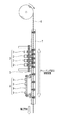
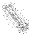
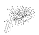
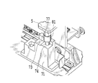
- FIG. 1 is a perspective view of a main part of a recording apparatus according to an embodiment of the present invention. Sectional drawing of the principal part of a recording device.
- FIG. 3 is a cross-sectional view illustrating a state during a cleaning operation of the recording apparatus.
- FIG. 3 is a side view showing a structure of a recording head.
- Front view showing the structure of the recording head
- the front view which shows the structure of a nozzle tip.
- Sectional drawing which shows the structure of a nozzle tip.
- the elements on larger scale which show the positional relationship of a nozzle tip and a suction nozzle.
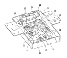
- the perspective view which shows the structure of a cleaning mechanism.
- the perspective view which shows the structure of a cleaning mechanism.
- blade The perspective view which shows the operation
- movement The figure which shows the state of the positioning member and head positioning member at the time of cleaning operation
- movement. 6 is a flowchart showing the operation of the cleaning mechanism in the first embodiment.
- FIG. 9 is a flowchart showing the operation of the cleaning mechanism in the second embodiment.
- FIG. 1 is a perspective view illustrating a configuration of a main part centering on a recording unit of a recording apparatus according to an embodiment
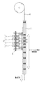
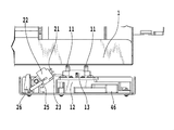
- FIG. 2 is a cross-sectional view illustrating a cross-sectional structure of the apparatus of FIG.
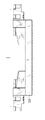
- FIG. 3 is a cross-sectional view showing a state during the cleaning operation.
- the ink jet recording apparatus of the present embodiment is a line printer that performs printing while continuously transporting a sheet in the transport direction (first direction) using a long line head.
- a holder for holding a sheet 4 such as continuous paper wound in a roll shape, a transport mechanism 7 for transporting the sheet 4 in a first direction at a predetermined speed, and a recording unit 3 for recording the sheet 4 with a line head are provided.
- the sheet is not limited to a continuous roll sheet, and may be a cut sheet.
- the recording apparatus 1 includes a cleaning unit 6 that cleans the nozzle surface of the recording head by wiping.
- a cutter unit for cutting the sheet 4 a drying unit for forcibly drying the sheet, and a discharge tray are provided downstream of the recording unit 3 along the sheet conveyance path.
- the recording unit 3 includes a plurality of recording heads 2 corresponding to different ink colors. In this example, four recording heads corresponding to four colors of CMYK are used, but the number of colors is not limited to this. Each color ink is supplied from the ink tank to the recording head 2 via an ink tube.
- the plurality of recording heads 2 are integrally held by a head holder 5 and have a mechanism for moving the head holder 5 up and down so that the distance between the plurality of recording heads 2 and the surface of the sheet 4 can be changed.
- the head holder 5 has a mechanism that translates the head holder 5 in a direction that intersects the first direction horizontally (second direction).
- the cleaning unit 6 has a plurality (four) of cleaning mechanisms 9 corresponding to a plurality (four) of the recording heads 2. Details of each cleaning mechanism 9 will be described later.
- the cleaning unit 6 is configured to be slidable in the first direction by a drive motor (not shown). 1 and 2 show a state during recording.
- the cleaning unit 6 is located downstream of the recording unit 3 in the sheet conveying direction.
- FIG. 3 shows a state during the cleaning operation, and the cleaning unit 6 is located immediately below the recording head 2 of the recording unit 3. 2 and 3, the movable range of the cleaning unit 6 is indicated by an arrow.
- the recording head 2 is a line-type recording head in which an inkjet nozzle row is formed in a range that covers the maximum width of a sheet that is assumed to be used.
- the arrangement direction of the nozzle rows is a direction (second direction) intersecting the first direction, for example, a direction orthogonal to the first direction.
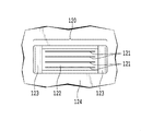
- a plurality of nozzle chips 120 are arranged along the longitudinal direction (second direction) on the base substrate 124 (on the common surface). As shown in FIG.
- a plurality (12 in this example) of nozzle chips 120 having the same size and the same structure are regularly provided over the entire longitudinal direction in a two-row staggered arrangement. That is, in the recording head 2, a plurality of first nozzle chips and a plurality of second nozzle chips each having a nozzle row are arranged along the longitudinal direction (second direction) as different rows and adjacent to each other. The first nozzle tip and the second nozzle tip are displaced in the longitudinal direction. Adjacent first nozzle chips and second nozzle chips are partially overlapped in the second direction in the nozzle rows included therein.
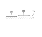
- the nozzle chip 120 includes a nozzle surface 122 on which a plurality of nozzle rows 121 for discharging ink is formed, and has a nozzle substrate in which energy elements formed corresponding to the respective nozzles are embedded. A plurality (four in this example) of nozzle rows 121 are arranged in parallel in four rows in the first direction.
- the nozzle substrate of the nozzle chip 120 is provided on the base substrate 124.
- the nozzle substrate and the base substrate 124 are connected by an electrical connection portion, and the electrical connection portion is covered with a sealing portion 123 made of a resin material, and is protected from corrosion and disconnection. As shown in FIG.
- the sealing portion 123 when the nozzle surface 122 is viewed from the side, the sealing portion 123 is formed on the base substrate 124 and protrudes in the ink ejection direction (referred to as the third direction) from the nozzle surface 122. It is a convex part.
- the sealing portion 123 is provided in the vicinity of the two end portions of the nozzle surface 122 in the nozzle row formation direction (second direction). As described above, the sealing portion 123 has a shape proximate to the plurality of nozzle rows 121 and protruding so as to protrude from the nozzle surface 122 with a gentle step in the ink ejection direction.
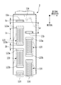
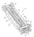
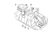
- FIG. 7 and 8 are perspective views showing detailed configurations of the cleaning unit 6 and one cleaning mechanism 9.
- FIG. 7 shows a state in which the cleaning mechanism is under the recording head 2 (during a cleaning operation)
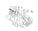
- FIG. 8 shows the cleaning mechanism 9 in a state where the recording head 2 is not present.
- the cleaning unit 6 is provided with a cleaning mechanism 9, a cap 51 and a positioning member 71.
- the cleaning mechanism 9 includes a cleaning unit 46 that wipes ink and dust adhering to the nozzle surface of the recording head 2, and a moving mechanism that moves the cleaning unit 46 in the cleaning direction (longitudinal direction of the recording head, that is, the second direction). And a frame 47 that supports them integrally.
- the cleaning unit 46 is a unit in which a wiper blade and a suction nozzle, which will be described later, are movable.
- the moving mechanism reciprocates the cleaning unit 46 guided and supported by the two shafts 45 in the longitudinal direction of the recording head 2 by driving the driving source.
- the drive source includes a drive motor 41 and reduction gears 42 and 43, and rotates the drive shaft 37. The rotation of the drive shaft 37 is transmitted by the belt 44 and the pulley to move the cleaning unit 46.
- the cleaning unit 46 removes ink and dust on the nozzle surface of the recording head 2 by a combination of a blade and a suction nozzle, as will be described later.
- a trigger lever 27 is provided outside the cleaning region of the frame 47 in order to switch the direction of the blade 21 described later.
- the cap 51 is held by the cap holder 52.
- the cap holder 52 is urged by a spring which is an elastic body in a direction perpendicular to the nozzle surface of the recording head 2 and can move against the spring.
- the recording head 2 moves in the direction perpendicular to the nozzle surface, and is brought into close contact with and separated from the cap 51.
- the positioning member 71 is in contact with a head positioning member 81 (not shown) provided in the head holder 5 (described in FIG. 15) during the cleaning operation and capping, so that the recording head 2 and the cleaning unit 6 in the first direction and second direction.
- the positional relationship in the direction and the direction perpendicular to the nozzle surface (third direction) is determined.
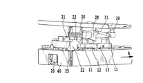
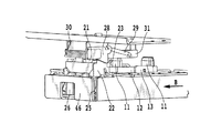
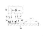
- FIG. 9 is a diagram showing the configuration of the cleaning unit 46.
- Two suction nozzles 11 as suction means are provided corresponding to the first and second nozzle chip rows.
- the two suction nozzles 11 have the same interval as the interval between the two nozzle chip rows in the first direction.
- the two suction nozzles 11 have the same or substantially the same amount of displacement (predetermined distance) between adjacent nozzle chips in the two nozzle chip rows in the second direction.
- the suction nozzle 11 is held by a suction holder 12, and the suction holder 12 is urged by a spring 14 that is an elastic body in a direction perpendicular to the nozzle surface of the recording head 2 (third direction). It can move in the direction.
- This displacement mechanism is for absorbing the movement of the moving suction nozzle 11 over the sealing portion 123. Details will be described later.
- a tube 15 is connected to the two suction nozzles 11 via a suction holder 12.
- a decompression means such as a suction pump is connected to the tube 15.
- the inside of the suction nozzle 11 is decompressed in order to suck ink and dust.
- a total of four blades 21 are held by the blade holder 22, two on each of the left and right blades 21.
- the blade holder 22 is pivotally supported at both ends in the first direction, and is configured to be rotatable about the first direction as a rotation axis. Normally, the blade holder 22 is biased by a spring 25 against a stopper 26.
- the blade 21 can switch the direction of the blade surface between a cleanable cleaning position and a retracted position by an operation of a switching mechanism described later.
- the suction holder 12 and the blade holder 22 are installed on a common support for the cleaning unit 46.
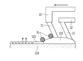
- FIG. 6 is a virtual partial enlarged view showing the relative positional relationship between the nozzle tip 120 of the recording head and the suction nozzle 11.
- a nozzle chip 120 and a nozzle chip 120 adjacent to the nozzle chip 120 in an adjacent row are arranged apart from each other by a predetermined distance Lh in the second direction.
- the two suction nozzles 11 include a first suction nozzle 11 a corresponding to the first nozzle chip row 125 and a second suction nozzle 11 b corresponding to the second nozzle chip row 126.
- the first suction nozzle 11a and the second suction nozzle 11b are spaced apart by the same distance as the distance between the first nozzle chip row 125 and the second nozzle chip row 126 (the distance between the centers). ing.
- the first suction nozzle 11a and the second suction nozzle 11b are arranged so that the openings of the suction nozzles are located in a range that covers a plurality of nozzle rows included in the corresponding nozzle chip 120 in the first direction.
- the first suction nozzle 11a and the second suction nozzle 11b are arranged so as to be separated from each other by a distance Lc in the second direction.
- the displacement distance Lh of the nozzle tip 120 and the displacement distance Lc of the suction nozzle are equal.
- the term “equal” here is not limited to exactly matching, but also includes substantially equality.
- the expression “equal” has the same meaning.
- the term “substantially equal” means that there is a moment when the first suction nozzle 11a and the second suction nozzle 11b simultaneously contact the sealing portion 123a and 123b.
- the displacement distance Lh and the displacement distance Lc are equal to the extent that the two suction nozzles do not touch the sealing portions of the corresponding nozzle chips at the same time.
- the first suction unit and the second suction unit are displaced in the second direction in correspondence with the shift in the second direction between adjacent first nozzle chips and second nozzle chips in different rows. It has become.
- Both the first suction nozzle 11a and the second suction nozzle 11b have a width Dc in the second direction.
- the width Dc is a range that covers a part of the nozzle row in the second direction, and corresponds to several to several tens of nozzles.
- the interval between the adjacent nozzle chips (first nozzle chip and second nozzle chip) 120 in the same row is a distance. Dh.
- the width Dc and the distance Dh are compared, the relationship of Dc ⁇ Dh is satisfied.
- a cleaner holder 31 is provided at a position facing the cleaning unit 46 outside the cleaning region.
- the cleaner holder 31 holds a blade cleaner 30 for scraping off ink adhering to the blade 21 when the recording head 2 is wiped.
- a release lever 28 is rotatably supported by the cleaner holder 31 while being biased by the tension of the spring 29. The release lever 28 is provided at a position where it can come into contact with the contact portion 23.
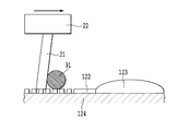
- FIG. 10A shows the state of the blade 21 when wiping the nozzle surface.
- the blade holder 22 has a normal orientation, and the blade 21 has a blade surface that is perpendicular to the nozzle surface of the recording head 2 (cleaning position).
- the tip of the blade 21 is closer to the nozzle surface of the recording head 2 than the tip of the suction nozzle 11.
- the cleaning unit 46 moves in the direction of arrow A in FIG. 10A, the blade 21 comes into contact with the blade cleaner 30, and ink and dust attached to the blade 21 are scraped off by the blade cleaner 30.
- the contact portion 23 of the cleaning unit 46 contacts the inclined surface of the release lever 28, and the inclined surface of the release lever 28 is pressed by the contact portion 23 and gradually rotates against the bias of the spring 29. Move.
- the contact portion 23 passes the slope of the release lever 28, the release lever 28 returns to the original state by the bias of the spring 29.
- FIG. 10B shows a state where the cleaning of the blade 21 is completed.
- the contact portion 23 contacts the end surface of the release lever 28. Even if the release lever 28 is pushed from this direction, the release lever 28 is fixed by the locking portion of the cleaner holder 31 and does not rotate. Therefore, the contact portion 23 is pushed by the release lever 28, and the blade holder 22 rotates in the direction opposite to the moving direction of the cleaning unit 46 against the urging force of the spring 25.
- the tensile force of the spring 25 works as a force in a direction to maintain the rotated state.
- FIG. 10C shows a state as a result of rotating the blade holder 22.
- the blade holder 22 is inclined and the blade 21 is inclined (retracted position) with the blade surface inclined with respect to the nozzle surface of the recording head 2.
- the tip of the blade 21 is located farther from the nozzle surface than the previous cleaning position, and is not in contact with the nozzle surface. That is, in the third direction, the tip of the suction nozzle 11 (the part closest to the nozzle surface of the suction means) is located between the position of the blade tip at the cleaning position and the position of the blade tip at the retracted position. It is a positional relationship.
- FIGS. 11A and 11B The operation of switching the blade 21 from the retracted position to the cleaning position will be described with reference to FIGS. 11A and 11B.
- the cleaning unit 46 moves in the direction of the arrow.
- the abutting portion 23 of the blade holder 22 abuts on the distal end portion of the trigger lever 27 fixed to the frame 47.
- the blade holder 22 is rotated by being pressed by the trigger lever 27, and the blade 21 moves to the cleaning position shown in FIG.
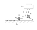
- FIG. 12A and 12B are side views for explaining the operation of the cleaning mechanism.
- FIG. 12A shows the state of the suction mode in which the recording head 2 is cleaned by the suction nozzle 11.
- FIG. 12B shows a wiping mode in which the recording head 2 is cleaned by the blade 21.
- the blade 21 is moved to the retracted position as shown in FIG. 12A.
- the position (suction mode position) in the third direction of the recording head 2 is set and held so that the tip of the suction nozzle 11 and the nozzle surface of the recording head 2 are in contact with each other.
- the cleaning unit 46 is moved in the longitudinal direction (second direction) while the suction nozzle 11 is decompressed by the decompression means, the ink and dust adhering to the nozzle can be sucked and removed from the suction nozzle 11.
- the suction nozzle 11 is pushed in the third direction by the sealing portion 123 protruding from the nozzle surface from the recording head 2.
- the suction holder 12 can be displaced in the direction of escape (third direction) with respect to the nozzle surface, so that even if the suction nozzle 11 is pushed, the movement of the suction holder 12 is changed. Can be escaped by. Note that it is not essential to bring the suction nozzle 11 into contact with the nozzle surface during suction cleaning. Suction can also be achieved by reducing the pressure in a state close to a very close position without contact. That is, in the suction mode, the suction nozzle 11 and the nozzle surface may be brought close to each other (including contact).
- the timing at which the first suction nozzle 11a and the second suction nozzle 11b face the sealing portion 123 of the corresponding nozzle chip 120 is equal. Thereafter, the timing at which the first suction nozzle 11a and the second suction nozzle 11b face the nozzle rows included in the first and second nozzle chips 120 is also equal.
- the suction nozzle 11 rides on the level difference of the sealing portion 123, a force in a direction for tilting the suction nozzle 11 is applied to the suction holder 12 via the suction nozzle 11 and tilts. Further, during the ride, the suction nozzle 11 is pressed and displaced in the third direction.
- the timing at which the first suction nozzle 11a and the second suction nozzle 11b ride on the sealing portions 123 in each row is substantially the same, the timing at which the suction holder 12 is tilted by these two suction nozzles is substantially the same.
- the timing at which the first suction nozzle 11a and the second suction nozzle 11b are pushed in the third direction is substantially the same. Therefore, the suction holder 12 is not tilted or pushed in while the first suction nozzle 11a and the second suction nozzle 11b are sucking, so that suction is not unstable. For the above reasons, the nozzle cleaning reliability is improved.
- the cleaning unit 46 In the suction mode (second cleaning means), the cleaning unit 46 is reciprocated in the second direction by the moving mechanism, and the pressure inside the suction nozzle 11, that is, the suction force is reduced between the backward movement and the forward movement. Means are controlled. Specifically, the pressure during the backward movement is reduced more than the pressure during the forward movement. Further, in the suction mode, the cleaning unit 46 reciprocates in the second direction, and the moving speed differs between the backward movement and the forward movement. Specifically, the speed during the backward movement is lower than that during the forward movement. When sucking back and forth, most of the ink and dust is absorbed in the first return path, and only a small amount of remaining ink and dust is removed in the next return path.
- the suction pressure is increased more reliably in the first operation by increasing the pressure reduction value / decreasing the moving speed and moving it slowly than in the forward path.
- the blade 21 is switched to the cleaning position as shown in FIG. 12B.
- the position (wiping mode position) of the recording head 2 in the third direction is set and held so that the tip of the blade 21 and the nozzle surface of the recording head 2 are in proper contact. At this time, the tip of the suction nozzle 11 and the nozzle surface of the recording head 2 are separated from the state of FIG. 12A.
- the decompression means stops.
- the cleaning unit 46 is moved in the second direction, the nozzle surface can be wiped by the blade 21 to remove ink and dust.
- the cleaning mechanism has two modes of the wiping mode and the suction mode, and the same cleaning unit 46 can selectively perform any mode in each cleaning direction.
- FIG. 13 is a perspective view of a positioning member 71 provided in the cleaning unit 6, and FIG. 14 is a side view of the positioning member 71.
- the positioning member 71 has a first third-direction contact surface 73, a second third-direction contact surface 74, and a third third-surface provided at different heights in the direction perpendicular to the nozzle surface (third direction).
- a three-direction contact surface 72 is provided. Further, it has first direction contact surfaces 76 and 77 that contact the head positioning member 81 in the first direction, and a second direction contact surface 75 that contacts in the second direction.
- FIG. 15A shows the positional relationship between the positioning member 71 and the head positioning member 81 during capping (capping position).
- FIG. 15B shows the positional relationship between the positioning member 71 and the head positioning member 81 in the suction mode (suction mode position).
- FIG. 15C shows the positional relationship between the positioning member 71 and the head positioning member 81 in the wiping mode (wiping mode position).
- the positioning member 71 provided in the cleaning unit 6 at the capping position is in contact with the head positioning member 81 provided on the head holder 5 in the first direction in the first direction and the second direction in the second direction. It is in contact with the direction contact surface 75. Further, in the third direction, it is in contact with the third third direction contact surface 72, thereby determining the positional relationship between the recording head 2 and the cleaning unit 6.
- the recording head 2 is in close contact with the cap 51, and capping the nozzle surface suppresses the drying of the nozzle.
- the positioning member 71 in the suction mode position, the positioning member 71 is in contact with the head positioning member 81 in the first direction with the first direction contact surface 77, and in the third direction, with the first third direction contact surface 73. It is in contact.
- the tip of the suction nozzle 11 and the nozzle surface of the recording head 2 are in contact with each other.
- the cleaning unit 46 is moved in the second direction while reducing the pressure inside the suction nozzle 11 by the pressure reducing means, the ink and dust adhering to the nozzle can be sucked from the suction nozzle 11 and removed.
- the positioning member 71 contacts the head positioning member 81 with the first direction contact surface 77 in the first direction, and in the third direction with the second third direction contact surface 74. It is in contact.
- the tip of the blade 21 and the nozzle surface of the recording head 2 are in proper contact with each other at the wiping mode position and the cleaning unit 46 is moved in the second direction, the nozzle surface is wiped by the blade 21 to wipe ink and dust. And can be removed.
- the first embodiment is characterized in that the suction mode is performed after the wiping mode is performed, and the moving direction (cleaning direction) of the cleaning unit 46 is different between the wiping mode and the suction mode. That is, the movement direction of the cleaning unit 46 in the wiping mode is selected as the second direction forward path (first cleaning direction), and the movement direction of the cleaning unit 46 in the suction mode is determined as the second direction return path (second cleaning direction). Select.
- the forward path in the second direction is the direction of the arrow A illustrated in FIG. 10A
- the backward path in the second direction is the direction of the arrow B illustrated in FIG. 10B.
- wiping wiping can be performed only in the forward path (first cleaning direction) due to the restriction of the switching mechanism.
- the blade when wiping is performed in the return path (second cleaning direction), the blade returns to the retracted position due to the frictional force between the blade and the nozzle surface. Therefore, when the suction mode is wiped in the return path, the movement time of the wiper unit can be shortened.
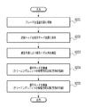
- FIG. 16 shows a flowchart of the cleaning operation in the first embodiment.
- the blade 21 is switched to the cleaning position as shown in FIG. 12B (S101). As shown in FIG. 15C, the positioning member 71 and the head positioning member 81 are held at the wiping mode position (S102). The cleaning unit 46 is moved in the outward direction in the second direction, and the wiping mode is performed (S103). The nozzle 21 and the base substrate 124, which is the chip mounting surface, are wiped by the blade 21, and ink and dust are wiped away. As a result, the nozzle surface can be cleaned without consuming ink from the nozzles. To implement the suction mode, the blade 21 is switched to the retracted position as shown in FIG. 12A (S104). As shown in FIG.
- the positioning member 71 and the head positioning member 81 are held at the suction mode position (S105).
- the cleaning unit 46 is moved to the return path in the second direction to implement the suction mode (S107).
- the suction nozzle 11 sucks ink and dust adhering to the nozzle surface and the nozzle. Accordingly, cleaning can be performed while suppressing ink consumption from the nozzles.
- FIG. 17A is a diagram illustrating a state before the blade 21 reaches the sealing portion from the nozzle surface in the first embodiment.
- FIG. 17A is a diagram illustrating a state in which the blade 21 wipes the nozzle surface 122 at the boundary between the nozzle surface 122 and the sealing portion 123 of FIG. 5B.
- the cleaning unit 46 is shown upside down.
- the blade holder 22 is moving at a rate of 5 inches / sec in the outward path in the second direction (right direction in FIG. 17A).
- the ink / dust 91 moves on the nozzle surface 122 while being in contact with the blade 21 and the nozzle surface 122, so that the ink / dust 91 attached to the nozzle surface 122 can be removed.
- FIG. 17B is a diagram illustrating a state after the blade 21 reaches the sealing portion from the nozzle surface in the first embodiment.
- FIG. 17B is a diagram illustrating a state in which the blade 21 wipes the sealing portion 123 at the boundary portion between the nozzle surface 122 and the sealing portion 123 in FIG. 5B.
- the blade holder 22 is moving at a rate of 5 inches / sec on the outward path in the second direction (right direction in FIG. 17B). Since the nozzle surface 122 and the sealing portion 123 have a level difference after reaching the sealing portion from the nozzle surface, a part of the ink / dust 91 adhering to the nozzle surface 122 is formed between the nozzle surface 122 and the sealing portion 123. Adhere to the boundary. Other ink / dust 91 moves in the sealing portion 123 while contacting the blade 21 and the sealing portion 123.
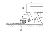
- FIG. 18A is a diagram showing a state before the suction means reaches the nozzle surface from the sealing portion in the first embodiment.
- 18A is a diagram illustrating a state where the suction nozzle 11 wipes the sealing portion 123 at the boundary portion between the nozzle surface 122 and the sealing portion 123 of FIG. 5B.
- the suction holder 12 moves at 0.5 inch / sec on the return path in the second direction (left direction in FIG. 18A).
- the ink / dust 91 is attached to the boundary portion between the nozzle surface 122 and the sealing portion 123.
- FIG. 18B is a diagram illustrating a state after the suction nozzle 11 reaches the nozzle surface 122 from the sealing portion 123 in the first embodiment.
- 18B is a diagram illustrating a state where the suction nozzle 11 wipes the nozzle surface 122 at the boundary between the nozzle surface 122 and the sealing portion 123 of FIG. 5B.
- the suction holder 12 is moving at 0.5 inch / sec in the return path in the second direction (left direction in FIG. 18B). After moving from the sealing portion 123 to the nozzle surface 122, the ink / dust 91 adhering to the boundary portion between the nozzle surface 122 and the sealing portion 123 is scraped off by the suction nozzle 11.
- a part of the scraped ink / dust 91 is sucked together with the ink / bubbles drawn from the nozzle by the pressure reduction inside the suction nozzle 11.
- Other ink / dust 91 moves on the nozzle surface 122 while contacting the suction nozzle 11 and the nozzle surface 122.
- the wiping mode and the suction mode are used together.
- the suction mode is performed twice, and the moving direction (cleaning direction) of the cleaning unit 46 is made different between the first suction mode and the second suction mode. That is, the moving direction of the cleaning unit 46 in the first suction mode selects the second direction, and the moving direction of the cleaning unit 46 in the second suction mode selects the second direction.
- the moving direction of the cleaning unit 46 in the first suction mode selects the second direction
- the moving direction of the cleaning unit 46 in the second suction mode selects the second direction.
- FIG. 19 shows a flowchart of the cleaning operation in the second embodiment.
- the blade 21 is switched to the retracted position as shown in FIG. 12A (S201).
- the positioning member 71 and the head positioning member 81 are held at the suction mode position (S202).
- the cleaning unit 46 is moved to the return path in the second direction to implement the first suction mode (S204).
- the suction nozzle 11 sucks ink and dust adhering to the nozzle surface and the nozzle.
- the cleaning unit 46 is moved to the outward path in the second direction to implement the second suction mode (S205).
- the ink consumption is larger than that in the first embodiment, cleaning can be performed with priority given to the recoverability of the nozzles.
- FIG. 20A is a diagram illustrating a state before the suction nozzle 11 reaches the sealing portion 123 from the nozzle surface 122 in the second embodiment.
- 20A is a diagram illustrating a state in which the suction nozzle 11 cleans the nozzle surface 122 at the boundary between the nozzle surface 122 and the sealing portion 123 in FIG. 5B.
- the cleaning unit 46 is shown upside down.
- the suction holder 12 is moving at 0.5 inch / sec in the outward path in the second direction (right direction in FIG. 20A).
- the ink / dust 91 moves on the nozzle surface 122 while being in contact with the suction nozzle 11 and the nozzle surface 122, so that the ink / dust 91 attached to the nozzle surface 122 can be removed. Further, since the suction nozzle 11 can suck a part of the ink / dust 91 together with the ink drawn from the nozzle, the absolute amount of the ink / dust 91 can be reduced as compared with the case of the first embodiment.
- FIG. 20B is a diagram illustrating a state after the suction nozzle 11 reaches the sealing portion 123 from the nozzle surface 122 in the second embodiment.
- 20B is a diagram illustrating a state in which the suction nozzle 11 has cleaned the sealing portion 123 at the boundary portion between the nozzle surface 122 and the sealing portion 123 of FIG. 5B.
- the suction holder 12 is moving at 0.5 inch / sec in the outward path in the second direction (right direction in FIG. 21A). Since the nozzle surface 122 and the sealing portion 123 have a level difference after reaching the sealing portion from the nozzle surface, a part of the ink / dust 91 adhering to the nozzle surface 122 is formed between the nozzle surface 122 and the sealing portion 123. Adhere to the boundary. Other ink / dust 91 moves through the sealing portion 123 while contacting the suction nozzle 11 and the sealing portion 123.
- FIG. 21A is a diagram illustrating a state before the suction nozzle 11 reaches the nozzle surface 122 from the sealing portion 123 in the second embodiment.
- FIG. 21A is a diagram illustrating a state where the suction nozzle 11 cleans the sealing portion 123 at the boundary portion between the nozzle surface 122 and the sealing portion 123 of FIG. 5B.
- the suction holder 12 moves at 0.5 inch / sec in the return path in the second direction (left direction in FIG. 21A).
- the ink / dust 91 is attached to the boundary between the nozzle surface 122 and the sealing portion 123 before reaching the nozzle surface from the sealing portion.
- FIG. 21B is a diagram illustrating a state after the suction nozzle 11 reaches the nozzle surface 122 from the sealing portion 123 in the second embodiment.
- FIG. 21B is a diagram illustrating a state where the suction nozzle 11 wipes the nozzle surface 122 at the boundary between the nozzle surface 122 and the sealing portion 123 of FIG. 5B.
- the suction holder 12 is moving at 0.5 inch / sec on the return path in the second direction (left direction in FIG. 21B). After reaching the nozzle surface 122 from the sealing portion 123, the ink / dust 91 adhering to the boundary between the nozzle surface 122 and the sealing portion 123 is scraped off by the suction nozzle 11.
- a part of the scraped ink / dust 91 is sucked together with the ink / bubbles pulled out from the nozzle by the pressure reduction in the suction nozzle 11.
- Other ink / dust 91 moves on the nozzle surface 122 while contacting the suction nozzle 11 and the nozzle surface 122.
- the wiping mode is described as 5 inch / sec, and the suction mode is described as 0.5 inch / sec.
- the wiping speed is not limited to this value.
- the wiping speed since the correlation between the wiping speed and the ink / dust removal property is low, the wiping speed is preferably as fast as possible from the viewpoint of throughput.
- the suction mode the correlation between the wiping speed and the ink / dust removal performance is high (the slower the wiping speed, the more ink is drawn from the nozzle and the higher the nozzle recovery performance). Is as late as possible.
- the recording head 2 includes a plurality of first nozzle chips each having a nozzle row and a plurality of second nozzle chips arranged in the second direction as different rows, and adjacent first nozzle chips.
- the second nozzle tip has a positional relationship shifted in the second direction.
- a part of nozzle row contained in the adjacent 1st nozzle chip and the 2nd nozzle chip overlaps in the 2nd direction.
- the present invention is not limited to this, and a system in which the recording head moves with respect to the cleaning unit to perform cleaning. It may be. That is, the present invention can be applied to a recording apparatus having an ink suction unit that is opposed to a part of nozzles of a nozzle array of a recording head and is relatively moved along the nozzle array forming direction. .
- the blade can be cleaned only in the first cleaning direction.
- the blade can also be implemented in the second cleaning direction.
- blade and a suction nozzle in common was demonstrated, it is also possible to provide the moving means to move separately.
Abstract
In this inkjet recording apparatus, the nozzle surface of a linear recording head having a plurality of nozzle chips regularly disposed thereon is more reliably cleaned. The inkjet recording apparatus has: a blade (22) which cleans, by wiping, the chip-mounted surface of a recording head, said chip-mounted surface including a nozzle surface; a suction nozzle (11), which cleans the chip-mounted surface by suction; and a moving means which moves, with respect to the recording head, the blade (22) and the suction nozzle (11) in the first cleaning direction and the second cleaning direction opposite to the first cleaning direction. The blade (22) or the suction nozzle (11) is selected so as to be used in each of the first and the second cleaning directions.
Description
本発明は、インクジェット記録装置に関する。
The present invention relates to an ink jet recording apparatus.
特許文献1は、インクジェット記録装置の記録ヘッドのノズル周辺の紙粉や塵埃を掻き取るための弾性体ブレードと、ノズル内部の気泡や増粘・固着したインクを吸引する吸引部とを組み合わせたクリーニング機構を開示している。このクリーニング機構は、弾性体ブレードと吸引部とをノズル列方向に移動させながらノズル周辺に付着した紙粉や塵埃を掻き取りながら、ノズル内部に混入した気泡や増粘・固着したインクを吸引する。
Patent Document 1 discloses a cleaning in which an elastic blade for scraping paper dust and dust around a nozzle of a recording head of an ink jet recording apparatus is combined with a suction unit that sucks bubbles and thickened / fixed ink inside the nozzle. A mechanism is disclosed. This cleaning mechanism sucks air bubbles and thickened / fixed ink mixed inside the nozzle while scraping paper dust and dust adhering to the periphery of the nozzle while moving the elastic blade and the suction part in the nozzle row direction. .
ところで、複数のノズルチップを千鳥配列のように規則的に配置したいわゆるライン型記録ヘッドでは、記録ヘッドのノズル形成面に、配線を封止する封止部が存在する。封止部はノズル形成面から突出しているので、封止部とノズル形成面との間には段差が生じる。
Incidentally, in a so-called line type recording head in which a plurality of nozzle chips are regularly arranged like a staggered arrangement, a sealing portion for sealing wiring exists on the nozzle forming surface of the recording head. Since the sealing part protrudes from the nozzle formation surface, a step is generated between the sealing part and the nozzle formation surface.
特許文献1に開示されたクリーニング機構を用いて、上記のようなライン型記録ヘッド記録ヘッドのノズル形成面をクリーニングすると、ブレードによって掻き取られた紙粉や塵埃などが段差に溜まりやすい。また、ブレードと吸引部とが一体的に形成され、ブレードによるワイピングの直後に吸引部による吸引が行われるため、段差に溜まった紙粉や塵埃を十分に吸い取ることができない。
When the nozzle forming surface of the above-described line type recording head recording head is cleaned using the cleaning mechanism disclosed in Patent Document 1, paper dust, dust, and the like scraped off by the blade are likely to accumulate in a step. Further, since the blade and the suction part are integrally formed and suction is performed by the suction part immediately after wiping by the blade, paper dust and dust accumulated in the step cannot be sufficiently sucked.
本発明の目的の一つは、複数のノズルチップを規則的に配置したライン型記録ヘッドのノズル面を、より確実にクリーニングすることができるインクジェット記録装置の提供である。
One of the objects of the present invention is to provide an ink jet recording apparatus capable of more reliably cleaning the nozzle surface of a line type recording head in which a plurality of nozzle chips are regularly arranged.
本発明のインクジェット記録装置は、ノズル列を有する複数のノズルチップが共通面上に配列された記録ヘッドを有するインクジェット記録装置であって、ノズル面を含む前記記録ヘッドのチップ搭載面をワイピングよりクリーニングする第1のクリーニング手段と、前記チップ搭載面を吸引によりクリーニングする第2のクリーニング手段と、前記記録ヘッドに対して前記第1および第2のクリーニング手段を第1のクリーニング方向および当該第1のクリーニング方向とは逆の第2の方向に移動させる移動手段と、前記第1および第2のクリーニング手段のうち、前記第1および第2のクリーニング方向の各々において実施するクリーニング手段をそれぞれ選択する選択手段とを有することを特徴とする。
The ink jet recording apparatus of the present invention is an ink jet recording apparatus having a recording head in which a plurality of nozzle chips having nozzle rows are arranged on a common surface, and cleaning the chip mounting surface of the recording head including the nozzle surface by wiping. First cleaning means for cleaning, second cleaning means for cleaning the chip mounting surface by suction, and the first and second cleaning means for the recording head in the first cleaning direction and the first cleaning direction. Selection for selecting a moving means for moving in a second direction opposite to the cleaning direction, and a cleaning means to be performed in each of the first and second cleaning directions, among the first and second cleaning means. Means.
本発明によれば、複数のノズルチップを規則的に配置したライン型記録ヘッドのノズル形成面をより確実にクリーニングすることができる。
According to the present invention, it is possible to more reliably clean the nozzle forming surface of a line type recording head in which a plurality of nozzle chips are regularly arranged.
(第1の実施形態)
図面を参照して本発明の実施形態を具体的に説明する。図1は実施形態に係る記録装置の記録部を中心とした主要部の構成を示す斜視図であり、図2は図1の装置の断面構造を示す断面図である。図3はクリーニング動作時の状態を示す断面図である。 (First embodiment)
Embodiments of the present invention will be specifically described with reference to the drawings. FIG. 1 is a perspective view illustrating a configuration of a main part centering on a recording unit of a recording apparatus according to an embodiment, and FIG. 2 is a cross-sectional view illustrating a cross-sectional structure of the apparatus of FIG. FIG. 3 is a cross-sectional view showing a state during the cleaning operation.
本実施形態のインクジェット記録装置(以下、記録装置という)は、長尺のラインヘッドを用いて、シートを搬送方向(第1方向)に連続搬送しながらプリントを行なうラインプリンタである。ロール状に巻かれた連続紙などのシート4を保持するホルダ、シート4を所定速度で第1方向に搬送する搬送機構7、シート4に対してラインヘッドで記録を行なう記録部3を備える。なお、シートは連続したロールシートに限らず、カットシートであってもよい。さらに、記録装置1は、記録ヘッドのノズル面をワイピングによってクリーニングするクリーニング部6を備える。さらに、シート搬送路に沿って、記録部3の下流にはシート4を切断するカッタユニット、シートを強制乾燥する乾燥ユニット、排出トレイを備えている。
The ink jet recording apparatus of the present embodiment (hereinafter referred to as a recording apparatus) is a line printer that performs printing while continuously transporting a sheet in the transport direction (first direction) using a long line head. A holder for holding a sheet 4 such as continuous paper wound in a roll shape, a transport mechanism 7 for transporting the sheet 4 in a first direction at a predetermined speed, and a recording unit 3 for recording the sheet 4 with a line head are provided. The sheet is not limited to a continuous roll sheet, and may be a cut sheet. Furthermore, the recording apparatus 1 includes a cleaning unit 6 that cleans the nozzle surface of the recording head by wiping. Further, a cutter unit for cutting the sheet 4, a drying unit for forcibly drying the sheet, and a discharge tray are provided downstream of the recording unit 3 along the sheet conveyance path.
記録部3は、異なるインク色にそれぞれ対応した複数の記録ヘッド2を備える。本例ではCMYKの4色に対応した4つの記録ヘッドとしているが、色数はこれには限定されない。各色のインクはインクタンクからそれぞれインクチューブを介して記録ヘッド2に供給される。複数の記録ヘッド2はヘッドホルダ5で一体に保持されており複数の記録ヘッド2とシート4の表面との間の距離を変更できるよう、ヘッドホルダ5を上下移動させる機構を有している。また、ヘッドホルダ5を第1方向と水平に交差する方向(第2方向)に平行移動させる機構を有している。
The recording unit 3 includes a plurality of recording heads 2 corresponding to different ink colors. In this example, four recording heads corresponding to four colors of CMYK are used, but the number of colors is not limited to this. Each color ink is supplied from the ink tank to the recording head 2 via an ink tube. The plurality of recording heads 2 are integrally held by a head holder 5 and have a mechanism for moving the head holder 5 up and down so that the distance between the plurality of recording heads 2 and the surface of the sheet 4 can be changed. In addition, the head holder 5 has a mechanism that translates the head holder 5 in a direction that intersects the first direction horizontally (second direction).
クリーニング部6は、複数(4つ)の記録ヘッド2に対応して複数(4つ)のクリーニング機構9を有する。各クリーニング機構9の詳細は後述する。クリーニング部6は駆動モータ(不図示)により、第1方向にスライド移動可能な構成となっている。図1および図2は記録時の状態を示し、クリーニング部6は記録部3に対してシート搬送方向下流に位置している。一方、図3はクリーニング動作時の状態を示し、クリーニング部6は記録部3の記録ヘッド2の直下に位置している。図2および図3にクリーニング部6の移動可能範囲を矢印で示している。
The cleaning unit 6 has a plurality (four) of cleaning mechanisms 9 corresponding to a plurality (four) of the recording heads 2. Details of each cleaning mechanism 9 will be described later. The cleaning unit 6 is configured to be slidable in the first direction by a drive motor (not shown). 1 and 2 show a state during recording. The cleaning unit 6 is located downstream of the recording unit 3 in the sheet conveying direction. On the other hand, FIG. 3 shows a state during the cleaning operation, and the cleaning unit 6 is located immediately below the recording head 2 of the recording unit 3. 2 and 3, the movable range of the cleaning unit 6 is indicated by an arrow.
図4Aおよび4Bは1つの記録ヘッド2の構造を示す。インクジェット方式は、発熱素子を用いた方式、ピエゾ素子を用いた方式、静電素子を用いた方式、MEMS素子を用いた方式等を採用することができる。記録ヘッド2は、使用が想定されるシートの最大幅をカバーする範囲でインクジェット方式のノズル列が形成されたライン型記録ヘッドである。ノズル列の並び方向は、第1方向と交差する方向(第2方向)、例えば、直交する方向である。ベース基板124の上(共通面上)に、複数のノズルチップ120が長手方向(第2方向)に沿って並んでいる。図4Bに示すように、同一寸法且つ同一構造の複数(本例では12個)のノズルチップ120が2列の千鳥配列で規則的に長手方向全域に渡って設けられている。すなわち、記録ヘッド2は、それぞれがノズル列を有する複数の第1ノズルチップと複数の第2ノズルチップとが、異なる列として長手方向(第2方向)に沿って並べられ、且つ、隣接する第1ノズルチップと第2ノズルチップは長手方向においてずれた位置関係となっている。隣接する第1ノズルチップと第2ノズルチップとは、これらに含まれるノズル列の一部が、第2方向においてオーバーラップしている。
4A and 4B show the structure of one recording head 2. As the inkjet method, a method using a heating element, a method using a piezo element, a method using an electrostatic element, a method using a MEMS element, or the like can be adopted. The recording head 2 is a line-type recording head in which an inkjet nozzle row is formed in a range that covers the maximum width of a sheet that is assumed to be used. The arrangement direction of the nozzle rows is a direction (second direction) intersecting the first direction, for example, a direction orthogonal to the first direction. A plurality of nozzle chips 120 are arranged along the longitudinal direction (second direction) on the base substrate 124 (on the common surface). As shown in FIG. 4B, a plurality (12 in this example) of nozzle chips 120 having the same size and the same structure are regularly provided over the entire longitudinal direction in a two-row staggered arrangement. That is, in the recording head 2, a plurality of first nozzle chips and a plurality of second nozzle chips each having a nozzle row are arranged along the longitudinal direction (second direction) as different rows and adjacent to each other. The first nozzle tip and the second nozzle tip are displaced in the longitudinal direction. Adjacent first nozzle chips and second nozzle chips are partially overlapped in the second direction in the nozzle rows included therein.
図5Aおよび5Bは記録ヘッド2を構成するノズルチップ120の1つの構造を示す。ノズルチップ120は、インク吐出する複数のノズル列121が形成されたノズル面122を備えると共に、各ノズルに対応して形成されたエネルギ素子が埋め込まれているノズル基板を有する。複数(本例では4つ)のノズル列121は第1方向に4列平行に並んでいる。ノズルチップ120のノズル基板はベース基板124の上に設けられている。ノズル基板とベース基板124との間は電気接続部で接続され、電気接続部は樹脂材からなる封止部123で被覆され、腐食や断線が起きないように保護されている。図5Bに示すように、ノズル面122を側方から見たとき、封止部123はベース基板124上に形成され、且つ、ノズル面122よりもインク吐出方向(第3方向という)に突出した凸部となっている。1つのノズルチップ120において、封止部123はノズル列の形成方向(第2方向)に関してノズル面122の両端2箇所の端部近傍に設けられている。このように、封止部123は複数のノズル列121に近接し、且つノズル面122よりもインク吐出方向になだらかな段差を持って突出するように盛り上がった形状を有している。
5A and 5B show one structure of the nozzle chip 120 constituting the recording head 2. The nozzle chip 120 includes a nozzle surface 122 on which a plurality of nozzle rows 121 for discharging ink is formed, and has a nozzle substrate in which energy elements formed corresponding to the respective nozzles are embedded. A plurality (four in this example) of nozzle rows 121 are arranged in parallel in four rows in the first direction. The nozzle substrate of the nozzle chip 120 is provided on the base substrate 124. The nozzle substrate and the base substrate 124 are connected by an electrical connection portion, and the electrical connection portion is covered with a sealing portion 123 made of a resin material, and is protected from corrosion and disconnection. As shown in FIG. 5B, when the nozzle surface 122 is viewed from the side, the sealing portion 123 is formed on the base substrate 124 and protrudes in the ink ejection direction (referred to as the third direction) from the nozzle surface 122. It is a convex part. In one nozzle chip 120, the sealing portion 123 is provided in the vicinity of the two end portions of the nozzle surface 122 in the nozzle row formation direction (second direction). As described above, the sealing portion 123 has a shape proximate to the plurality of nozzle rows 121 and protruding so as to protrude from the nozzle surface 122 with a gentle step in the ink ejection direction.
図7および図8はクリーニング部6と1つのクリーニング機構9の詳細構成を示す斜視図である。図7は記録ヘッド2の下にクリーニング機構がある状態(クリーニング動作時)、図8は記録ヘッド2がいない状態でクリーニング機構9が露出している。クリーニング部6には、クリーニング機構9、キャップ51および位置決め部材71が設けられている。
7 and 8 are perspective views showing detailed configurations of the cleaning unit 6 and one cleaning mechanism 9. FIG. 7 shows a state in which the cleaning mechanism is under the recording head 2 (during a cleaning operation), and FIG. 8 shows the cleaning mechanism 9 in a state where the recording head 2 is not present. The cleaning unit 6 is provided with a cleaning mechanism 9, a cap 51 and a positioning member 71.
クリーニング機構9は、記録ヘッド2のノズル面に付着したインクおよびゴミを払拭するクリーニングユニット46と、クリーニングユニット46をクリーニング方向(記録ヘッドの長手方向、すなわち、第2方向)に移動させる移動機構と、これらを一体に支持するフレーム47とを有する。クリーニングユニット46は後述するワイパブレードや吸引ノズルが1つの移動可能なユニットとなっている。移動機構は、駆動源の駆動によって、2本のシャフト45によって案内支持されたクリーニングユニット46を記録ヘッド2の長手方向に往復移動させる。駆動源は、駆動モータ41と減速ギア42、43を有し、ドライブシャフト37を回転させる。ドライブシャフト37の回転は、ベルト44とプーリで伝達されてクリーニングユニット46を移動させる。クリーニングユニット46は、後述するようにブレードと吸引ノズルの組み合わせによって、記録ヘッド2のノズル面のインクやゴミの除去を行なうものである。フレーム47のクリーニング領域外には、後述するブレード21の向きの切り替えを行なうためにトリガレバー27が設けられている。
The cleaning mechanism 9 includes a cleaning unit 46 that wipes ink and dust adhering to the nozzle surface of the recording head 2, and a moving mechanism that moves the cleaning unit 46 in the cleaning direction (longitudinal direction of the recording head, that is, the second direction). And a frame 47 that supports them integrally. The cleaning unit 46 is a unit in which a wiper blade and a suction nozzle, which will be described later, are movable. The moving mechanism reciprocates the cleaning unit 46 guided and supported by the two shafts 45 in the longitudinal direction of the recording head 2 by driving the driving source. The drive source includes a drive motor 41 and reduction gears 42 and 43, and rotates the drive shaft 37. The rotation of the drive shaft 37 is transmitted by the belt 44 and the pulley to move the cleaning unit 46. The cleaning unit 46 removes ink and dust on the nozzle surface of the recording head 2 by a combination of a blade and a suction nozzle, as will be described later. A trigger lever 27 is provided outside the cleaning region of the frame 47 in order to switch the direction of the blade 21 described later.
図8において、キャップ51はキャップホルダ52に保持されている。キャップホルダ52は記録ヘッド2のノズル面に対して垂直方向に弾性体であるバネで付勢され、バネに抗して移動可能となっている。フレーム47がキャップ位置にある状態で記録ヘッド2がノズル面に対して垂直方向に移動して、キャップ51と密着および離間を行なう。密着によってノズル面をキャッピングすることでノズルの乾燥が抑制される。位置決め部材71はクリーニング動作時およびキャッピング時においてヘッドホルダ5に設けられた不図示のヘッド位置決め部材81(図15に記載)と当接することで記録ヘッド2とクリーニング部6の第1方向、第2方向ならびにノズル面に対して垂直方向(第3方向)の位置関係を決める構成となっている。
In FIG. 8, the cap 51 is held by the cap holder 52. The cap holder 52 is urged by a spring which is an elastic body in a direction perpendicular to the nozzle surface of the recording head 2 and can move against the spring. With the frame 47 in the cap position, the recording head 2 moves in the direction perpendicular to the nozzle surface, and is brought into close contact with and separated from the cap 51. By capping the nozzle surface by close contact, drying of the nozzle is suppressed. The positioning member 71 is in contact with a head positioning member 81 (not shown) provided in the head holder 5 (described in FIG. 15) during the cleaning operation and capping, so that the recording head 2 and the cleaning unit 6 in the first direction and second direction. The positional relationship in the direction and the direction perpendicular to the nozzle surface (third direction) is determined.
図9はクリーニングユニット46の構成を示す図である。第1、第2のノズルチップ列に対応して吸引手段としての2つの吸引ノズル11が設けられている。2つの吸引ノズル11は、第1方向においては2つのノズルチップ列の間隔と同じ間隔を有する。2つの吸引ノズル11は、第2方向においては2つのノズルチップ列の隣り合うノズルチップの間のずれ量(所定距離)と同じかほぼ同じずれ量を有している。吸引ノズル11は吸引ホルダ12に保持され、吸引ホルダ12は記録ヘッド2のノズル面に対して垂直方向(第3方向)に弾性体であるバネ14で付勢され、バネに抗して第3方向に移動可能となっている。この変位機構は、移動中の吸引ノズル11が封止部123を乗り越える際の動きを吸収するためのものである。詳しくは後述する。
FIG. 9 is a diagram showing the configuration of the cleaning unit 46. Two suction nozzles 11 as suction means are provided corresponding to the first and second nozzle chip rows. The two suction nozzles 11 have the same interval as the interval between the two nozzle chip rows in the first direction. The two suction nozzles 11 have the same or substantially the same amount of displacement (predetermined distance) between adjacent nozzle chips in the two nozzle chip rows in the second direction. The suction nozzle 11 is held by a suction holder 12, and the suction holder 12 is urged by a spring 14 that is an elastic body in a direction perpendicular to the nozzle surface of the recording head 2 (third direction). It can move in the direction. This displacement mechanism is for absorbing the movement of the moving suction nozzle 11 over the sealing portion 123. Details will be described later.
2つの吸引ノズル11には吸引ホルダ12を介してチューブ15が接続されている。チューブ15には吸引ポンプ等の減圧手段が接続されている。減圧手段を動作させると、吸引ノズル11の内部は、インクやゴミを吸い取るために減圧される。ブレード21は左右2枚ずつ、計4枚のブレードがブレードホルダ22に保持されている。ブレードホルダ22は第1方向における両端が軸支され、第1方向を回転軸として回転可能な構造となっており、通常はブレードホルダ22はストッパ26にバネ25によって付勢されている。ブレード21は、後述する切換機構の動作により、クリーニング可能なクリーニング位置と退避位置とでブレード面の向きを切り換えることができる。吸引ホルダ12とブレードホルダ22はクリーニングユニット46の共通の支持体上に設置されている。
A tube 15 is connected to the two suction nozzles 11 via a suction holder 12. A decompression means such as a suction pump is connected to the tube 15. When the decompression means is operated, the inside of the suction nozzle 11 is decompressed in order to suck ink and dust. A total of four blades 21 are held by the blade holder 22, two on each of the left and right blades 21. The blade holder 22 is pivotally supported at both ends in the first direction, and is configured to be rotatable about the first direction as a rotation axis. Normally, the blade holder 22 is biased by a spring 25 against a stopper 26. The blade 21 can switch the direction of the blade surface between a cleanable cleaning position and a retracted position by an operation of a switching mechanism described later. The suction holder 12 and the blade holder 22 are installed on a common support for the cleaning unit 46.
図6は記録ヘッドのノズルチップ120と吸引ノズル11との相対的な位置関係を示す仮想部分拡大図である。2列の千鳥配列において、あるノズルチップ120と、そのノズルチップ120に隣の列で隣接しているノズルチップ120とは、第2方向において所定の距離Lhだけ離れて配置されている。一方、2つの吸引ノズル11は、第1のノズルチップ列125に対応した第1吸引ノズル11aと、第2のノズルチップ列126に対応した第2吸引ノズル11bからなる。第1吸引ノズル11aと第2吸引ノズル11bは、第1方向においては、第1ノズルチップ列125と第2ノズルチップ列126の間の距離(中心間の距離)と同じ距離だけ離れて配置されている。また、第1吸引ノズル11aと第2吸引ノズル11bは、第1方向において対応するノズルチップ120に含まれる複数のノズル列をカバーする範囲に吸引ノズルの開口が位置するように配置されている。第1吸引ノズル11aと第2吸引ノズル11bとは、第2方向においては距離Lcだけ離れてずれて配置されている。ここで、第2方向において、ノズルチップ120のずれの距離Lhと吸引ノズルのずれの距離Lcとは等しい。ここで言う「等しい」とは厳密に一致することには限定されず、略等しいことも含む意味であり、本発明において「等しい」との表現は同意味とする。ここでいう略等しいとは、第1吸引ノズル11aが封止部123aに、第2吸引ノズル11bが封止部123bに同時に当接する瞬間が存在する程度ということである。言い換えると、ずれの距離Lhとずれの距離Lcとは、2つの吸引ノズルが対応するノズルチップの封止部に同時に触れないことはない程度に等しい。このように、第1吸引手段と第2吸引手段とは、異なる列の隣接する第1ノズルチップと第2ノズルチップの第2方向でのずれに対応して、第2方向でずれた位置関係となっている。
FIG. 6 is a virtual partial enlarged view showing the relative positional relationship between the nozzle tip 120 of the recording head and the suction nozzle 11. In a two-row zigzag arrangement, a nozzle chip 120 and a nozzle chip 120 adjacent to the nozzle chip 120 in an adjacent row are arranged apart from each other by a predetermined distance Lh in the second direction. On the other hand, the two suction nozzles 11 include a first suction nozzle 11 a corresponding to the first nozzle chip row 125 and a second suction nozzle 11 b corresponding to the second nozzle chip row 126. In the first direction, the first suction nozzle 11a and the second suction nozzle 11b are spaced apart by the same distance as the distance between the first nozzle chip row 125 and the second nozzle chip row 126 (the distance between the centers). ing. In addition, the first suction nozzle 11a and the second suction nozzle 11b are arranged so that the openings of the suction nozzles are located in a range that covers a plurality of nozzle rows included in the corresponding nozzle chip 120 in the first direction. The first suction nozzle 11a and the second suction nozzle 11b are arranged so as to be separated from each other by a distance Lc in the second direction. Here, in the second direction, the displacement distance Lh of the nozzle tip 120 and the displacement distance Lc of the suction nozzle are equal. The term “equal” here is not limited to exactly matching, but also includes substantially equality. In the present invention, the expression “equal” has the same meaning. Here, the term “substantially equal” means that there is a moment when the first suction nozzle 11a and the second suction nozzle 11b simultaneously contact the sealing portion 123a and 123b. In other words, the displacement distance Lh and the displacement distance Lc are equal to the extent that the two suction nozzles do not touch the sealing portions of the corresponding nozzle chips at the same time. As described above, the first suction unit and the second suction unit are displaced in the second direction in correspondence with the shift in the second direction between adjacent first nozzle chips and second nozzle chips in different rows. It has become.
第1吸引ノズル11a、第2吸引ノズル11bは共に、第2方向において幅Dcを有している。幅Dcは第2方向においてノズル列の一部をカバーする範囲であり、ノズル数本~数十本に相当する幅である。記録ヘッド2は、第2方向に沿った各列において、同じ列の隣り合うノズルチップ(第1ノズルチップと第2ノズルチップ)120の間隔(封止部の端部の間隔)はいずれも距離Dhである。ここで、幅Dcと距離Dhを比較すると、Dc<Dhの関係を満たしている。このような位置関係を満たすことで、隣接する吸引ノズル11の間隔を狭めることでき、第1方向にノズルチップ間の間隔が広がることを抑え、装置の大型化が抑制される。
Both the first suction nozzle 11a and the second suction nozzle 11b have a width Dc in the second direction. The width Dc is a range that covers a part of the nozzle row in the second direction, and corresponds to several to several tens of nozzles. In the recording head 2, in each row along the second direction, the interval between the adjacent nozzle chips (first nozzle chip and second nozzle chip) 120 in the same row (the interval between the end portions of the sealing portion) is a distance. Dh. Here, when the width Dc and the distance Dh are compared, the relationship of Dc <Dh is satisfied. By satisfying such a positional relationship, the interval between the adjacent suction nozzles 11 can be narrowed, and the increase in the interval between the nozzle chips in the first direction is suppressed, and the increase in size of the apparatus is suppressed.
次に、ブレード21をクリーニング位置から退避位置に切り換える動作について、図10A~10Cを用いて説明する。図10A~10Cにおいて、クリーニング領域外においてクリーニングユニット46と対向する位置にクリーナホルダ31が設けられている。クリーナホルダ31には、記録ヘッド2をワイピングした際にブレード21に付着したインクを掻き取るためのブレードクリーナ30が保持されている。クリーナホルダ31には、リリースレバー28がバネ29の引張りによって付勢されながら回動可能に支持されている。リリースレバー28は当接部23と当接し得る位置に設けられている。
Next, the operation of switching the blade 21 from the cleaning position to the retracted position will be described with reference to FIGS. 10A to 10C. 10A to 10C, a cleaner holder 31 is provided at a position facing the cleaning unit 46 outside the cleaning region. The cleaner holder 31 holds a blade cleaner 30 for scraping off ink adhering to the blade 21 when the recording head 2 is wiped. A release lever 28 is rotatably supported by the cleaner holder 31 while being biased by the tension of the spring 29. The release lever 28 is provided at a position where it can come into contact with the contact portion 23.
図10Aはノズル面をワイピングする際のブレード21の状態を示す。ブレードホルダ22は通常の向きであり、ブレード21はブレード面が記録ヘッド2のノズル面に対して垂直な向き(クリーニング位置)となっている。この状態においては、ブレード21の先端部は吸引ノズル11の先端部より、記録ヘッド2のノズル面により近い位置関係となっている。ここで、図10Aの矢印A方向にクリーニングユニット46が移動すると、ブレード21はブレードクリーナ30と接触して、ブレード21に付着したインクやゴミがブレードクリーナ30に掻き取られる。この動作の途中で、クリーニングユニット46の当接部23がリリースレバー28の斜面に当接し、リリースレバー28の斜面は当接部23に押圧されてバネ29の付勢に抗して徐々に回動する。当接部23がリリースレバー28の斜面を通り過ぎると、バネ29の付勢によってリリースレバー28は元の状態に戻る。
FIG. 10A shows the state of the blade 21 when wiping the nozzle surface. The blade holder 22 has a normal orientation, and the blade 21 has a blade surface that is perpendicular to the nozzle surface of the recording head 2 (cleaning position). In this state, the tip of the blade 21 is closer to the nozzle surface of the recording head 2 than the tip of the suction nozzle 11. Here, when the cleaning unit 46 moves in the direction of arrow A in FIG. 10A, the blade 21 comes into contact with the blade cleaner 30, and ink and dust attached to the blade 21 are scraped off by the blade cleaner 30. In the middle of this operation, the contact portion 23 of the cleaning unit 46 contacts the inclined surface of the release lever 28, and the inclined surface of the release lever 28 is pressed by the contact portion 23 and gradually rotates against the bias of the spring 29. Move. When the contact portion 23 passes the slope of the release lever 28, the release lever 28 returns to the original state by the bias of the spring 29.
図10Bは、ブレード21のクリーニングが終了した状態を示す。ここで、図10Bの矢印Bの方向にクリーニングユニット46が移動すると、当接部23がリリースレバー28の端面に当接する。この方向からリリースレバー28を押しても、リリースレバー28はクリーナホルダ31の係止部によって固定されており回動しない。そのため、リリースレバー28に当接部23が押されて、ブレードホルダ22がバネ25の引張りによる付勢に抗してクリーニングユニット46の進行方向と反対方向に回動する。回動が終わるとバネ25の引張力が回動した状態を維持する方向の力として働く。
FIG. 10B shows a state where the cleaning of the blade 21 is completed. Here, when the cleaning unit 46 moves in the direction of arrow B in FIG. 10B, the contact portion 23 contacts the end surface of the release lever 28. Even if the release lever 28 is pushed from this direction, the release lever 28 is fixed by the locking portion of the cleaner holder 31 and does not rotate. Therefore, the contact portion 23 is pushed by the release lever 28, and the blade holder 22 rotates in the direction opposite to the moving direction of the cleaning unit 46 against the urging force of the spring 25. When the rotation is finished, the tensile force of the spring 25 works as a force in a direction to maintain the rotated state.
図10Cは、ブレードホルダ22が回動した結果の状態を示す。ブレードホルダ22は傾いた向きであり、ブレード21はブレード面が記録ヘッド2のノズル面に対して傾いた向き(退避位置)となっている。この状態においては、ブレード21の先端部は、先のクリーニング位置に較べてノズル面からより離れた位置になり、ノズル面とは非接触である。つまり、第3方向において、クリーニング位置におけるブレード先端部の位置と、退避位置におけるブレード先端部の位置の間に、吸引ノズル11の先端部(吸引手段のノズル面に最も近い部位)があるような位置関係となっている。
FIG. 10C shows a state as a result of rotating the blade holder 22. The blade holder 22 is inclined and the blade 21 is inclined (retracted position) with the blade surface inclined with respect to the nozzle surface of the recording head 2. In this state, the tip of the blade 21 is located farther from the nozzle surface than the previous cleaning position, and is not in contact with the nozzle surface. That is, in the third direction, the tip of the suction nozzle 11 (the part closest to the nozzle surface of the suction means) is located between the position of the blade tip at the cleaning position and the position of the blade tip at the retracted position. It is a positional relationship.
ブレード21を退避位置からクリーニング位置に切り換える動作について、図11Aおよび11Bを用いて説明する。ブレード21が退避位置にある図11Aの状態において、クリーニングユニット46が矢印方向へ移動する。ブレードホルダ22の当接部23は、フレーム47に固設されたトリガレバー27の先端部に当接する。さらに移動すると、トリガレバー27に押圧されてブレードホルダ22が回動して、ブレード21は、図11Bに示すクリーニング位置に移行して切り換えが完了する。
The operation of switching the blade 21 from the retracted position to the cleaning position will be described with reference to FIGS. 11A and 11B. In the state of FIG. 11A where the blade 21 is in the retracted position, the cleaning unit 46 moves in the direction of the arrow. The abutting portion 23 of the blade holder 22 abuts on the distal end portion of the trigger lever 27 fixed to the frame 47. When further moved, the blade holder 22 is rotated by being pressed by the trigger lever 27, and the blade 21 moves to the cleaning position shown in FIG.
図12Aおよび12Bはクリーニング機構の動作を説明するための側面図である。図12Aは吸引ノズル11によって記録ヘッド2のクリーニングを行っている吸引モードの状態である。図12Bはブレード21によって記録ヘッド2のクリーニングを行っているワイピングモードの状態である。
12A and 12B are side views for explaining the operation of the cleaning mechanism. FIG. 12A shows the state of the suction mode in which the recording head 2 is cleaned by the suction nozzle 11. FIG. 12B shows a wiping mode in which the recording head 2 is cleaned by the blade 21.
吸引モードでは、図12Aのように、ブレード21を退避位置にする。吸引ノズル11の先端部と記録ヘッド2のノズル面とが接触するように、記録ヘッド2の第3方向における位置(吸引モード位置)を設定して保持する。減圧手段により吸引ノズル11内を減圧させながら、クリーニングユニット46を長手方向(第2方向)に移動させると、ノズルに付着したインクやゴミを吸引ノズル11から吸引し除去することができる。クリーニングユニット46が第2方向に移動する最中に、記録ヘッド2からノズル面よりも突出した封止部123に吸引ノズル11が第3方向に押される。上述したように、クリーニングユニット46において吸引ホルダ12は、ノズル面に対して逃げる方向(第3方向)に変位可能となっているので、吸引ノズル11が押されもその動きを吸引ホルダ12の変位によって逃がすことができる。なお、吸引のクリーニングの際に、吸引ノズル11とノズル面とを接触させることは必須ではない。接触させずに極めて近い位置まで近づけた状態で減圧することによっても吸引できる。すなわち、吸引モードにおいては、吸引ノズル11とノズル面とは近接(当接を含む)させればよい。
In the suction mode, the blade 21 is moved to the retracted position as shown in FIG. 12A. The position (suction mode position) in the third direction of the recording head 2 is set and held so that the tip of the suction nozzle 11 and the nozzle surface of the recording head 2 are in contact with each other. When the cleaning unit 46 is moved in the longitudinal direction (second direction) while the suction nozzle 11 is decompressed by the decompression means, the ink and dust adhering to the nozzle can be sucked and removed from the suction nozzle 11. While the cleaning unit 46 moves in the second direction, the suction nozzle 11 is pushed in the third direction by the sealing portion 123 protruding from the nozzle surface from the recording head 2. As described above, in the cleaning unit 46, the suction holder 12 can be displaced in the direction of escape (third direction) with respect to the nozzle surface, so that even if the suction nozzle 11 is pushed, the movement of the suction holder 12 is changed. Can be escaped by. Note that it is not essential to bring the suction nozzle 11 into contact with the nozzle surface during suction cleaning. Suction can also be achieved by reducing the pressure in a state close to a very close position without contact. That is, in the suction mode, the suction nozzle 11 and the nozzle surface may be brought close to each other (including contact).
上述した図6のように、距離Lhと距離Lcが等しいので、第1吸引ノズル11aと第2吸引ノズル11bがそれぞれ対応するノズルチップ120の封止部123と対向するタイミングは等しくなる。その後、第1吸引ノズル11aと第2吸引ノズル11bが第1および第2のノズルチップ120に含まれるノズル列に対向するタイミングも等しくなる。吸引ノズル11が封止部123の段差に乗り上げる際には、吸引ノズル11をチルトさせる方向の力が、吸引ノズル11を介して吸引ホルダ12に加わって傾く。また、乗り上げている最中には吸引ノズル11は第3方向に押圧されて変位する。第1吸引ノズル11aおよび第2吸引ノズル11bが各列の封止部123に乗り上げるタイミングは略同じなので、これら2つの吸引ノズルによる吸引ホルダ12が傾くタイミングは略同じである。第1吸引ノズル11aおよび第2吸引ノズル11bが第3方向に押し込まれるタイミングもほぼ同じである。そのため、第1吸引ノズル11aと第2吸引ノズル11bとが吸引している最中には、吸引ホルダ12が傾いたり押し込まれたりして、吸引が不安定になることがない。以上の理由により、ノズルのクリーニング信頼性が向上する。
As shown in FIG. 6 described above, since the distance Lh and the distance Lc are equal, the timing at which the first suction nozzle 11a and the second suction nozzle 11b face the sealing portion 123 of the corresponding nozzle chip 120 is equal. Thereafter, the timing at which the first suction nozzle 11a and the second suction nozzle 11b face the nozzle rows included in the first and second nozzle chips 120 is also equal. When the suction nozzle 11 rides on the level difference of the sealing portion 123, a force in a direction for tilting the suction nozzle 11 is applied to the suction holder 12 via the suction nozzle 11 and tilts. Further, during the ride, the suction nozzle 11 is pressed and displaced in the third direction. Since the timing at which the first suction nozzle 11a and the second suction nozzle 11b ride on the sealing portions 123 in each row is substantially the same, the timing at which the suction holder 12 is tilted by these two suction nozzles is substantially the same. The timing at which the first suction nozzle 11a and the second suction nozzle 11b are pushed in the third direction is substantially the same. Therefore, the suction holder 12 is not tilted or pushed in while the first suction nozzle 11a and the second suction nozzle 11b are sucking, so that suction is not unstable. For the above reasons, the nozzle cleaning reliability is improved.
吸引モード(第2のクリーニング手段)では、移動機構によりクリーニングユニット46が第2方向で往復移動し、復路移動時と往路移動時とで吸引ノズル11内部の圧力、すなわち吸引力が異なるように減圧手段が制御される。具体的には、復路移動時の圧力を往路移動時の圧力よりも大きく減圧する。更に、吸引モードでは、クリーニングユニット46が第2方向に往復移動し、復路移動時と往路移動時で移動速度が異なる。具体的には、復路移動時の方が往路移動時よりも速度が小さい。往復で吸引する際には、最初の復路で大半のインクやゴミが吸収され、次の往路では残った僅かなインクやゴミを除去するに過ぎない。従って、より多くのインクを吸収する復路において往路よりも減圧値を大きくする/移動速度を小さくしてゆっくり動かすことで、最初の動作でより確実に多量の吸引が行なわれる。往路では減圧値を小さくする/速度を大きくすることで、消費電力や動作音の低減/往復動作のトータル時間を短くすることができる。
In the suction mode (second cleaning means), the cleaning unit 46 is reciprocated in the second direction by the moving mechanism, and the pressure inside the suction nozzle 11, that is, the suction force is reduced between the backward movement and the forward movement. Means are controlled. Specifically, the pressure during the backward movement is reduced more than the pressure during the forward movement. Further, in the suction mode, the cleaning unit 46 reciprocates in the second direction, and the moving speed differs between the backward movement and the forward movement. Specifically, the speed during the backward movement is lower than that during the forward movement. When sucking back and forth, most of the ink and dust is absorbed in the first return path, and only a small amount of remaining ink and dust is removed in the next return path. Therefore, in the return path that absorbs more ink, the suction pressure is increased more reliably in the first operation by increasing the pressure reduction value / decreasing the moving speed and moving it slowly than in the forward path. By reducing the pressure reduction value / increasing the speed in the forward path, it is possible to reduce power consumption and operation sound / total time for reciprocation.
一方、ワイピングモード(第1のクリーニング手段)では、図12Bのように、ブレード21をクリーニング位置に切り換える。ブレード21の先端部と記録ヘッド2のノズル面とが適切に接触するように、記録ヘッド2の第3方向における位置(ワイピングモード位置)を設定して保持する。このとき、吸引ノズル11の先端部と記録ヘッド2のノズル面とは、図12Aの状態よりも離れる。減圧手段は停止する。クリーニングユニット46を第2方向に移動させると、ブレード21によりノズル面をワイピングしてインクやゴミを払拭して除去することができる。
On the other hand, in the wiping mode (first cleaning means), the blade 21 is switched to the cleaning position as shown in FIG. 12B. The position (wiping mode position) of the recording head 2 in the third direction is set and held so that the tip of the blade 21 and the nozzle surface of the recording head 2 are in proper contact. At this time, the tip of the suction nozzle 11 and the nozzle surface of the recording head 2 are separated from the state of FIG. 12A. The decompression means stops. When the cleaning unit 46 is moved in the second direction, the nozzle surface can be wiped by the blade 21 to remove ink and dust.
以上のように、クリーニング機構は、ワイピングモードと吸引モードの2つのモードを有し、同一のクリーニングユニット46でいずれかのモードを、各クリーニング方向において選択的に実施することが可能である。
As described above, the cleaning mechanism has two modes of the wiping mode and the suction mode, and the same cleaning unit 46 can selectively perform any mode in each cleaning direction.
図13はクリーニング部6に設けられた位置決め部材71の斜視図を示し、図14は位置決め部材71の側面図を示す。位置決め部材71はノズル面に対して垂直方向(第3方向)において異なる高さに設けられた第1の第3方向当接面73、第2の第3方向当接面74、第3の第3方向当接面72を有する。また、ヘッド位置決め部材81と第1方向において当接する第1方向当接面76、77と、第2方向において当接する第2方向当接面75を有する。
FIG. 13 is a perspective view of a positioning member 71 provided in the cleaning unit 6, and FIG. 14 is a side view of the positioning member 71. The positioning member 71 has a first third-direction contact surface 73, a second third-direction contact surface 74, and a third third-surface provided at different heights in the direction perpendicular to the nozzle surface (third direction). A three-direction contact surface 72 is provided. Further, it has first direction contact surfaces 76 and 77 that contact the head positioning member 81 in the first direction, and a second direction contact surface 75 that contacts in the second direction.
図15Aはキャッピング時における位置決め部材71とヘッド位置決め部材81の位置関係を示す(キャッピング位置)。図15Bは吸引モードにおける位置決め部材71とヘッド位置決め部材81の位置関係を示す(吸引モード位置)。図15Cはワイピングモードにおける位置決め部材71とヘッド位置決め部材81の位置関係を示す(ワイピングモード位置)。
FIG. 15A shows the positional relationship between the positioning member 71 and the head positioning member 81 during capping (capping position). FIG. 15B shows the positional relationship between the positioning member 71 and the head positioning member 81 in the suction mode (suction mode position). FIG. 15C shows the positional relationship between the positioning member 71 and the head positioning member 81 in the wiping mode (wiping mode position).
図15Aのようにキャッピング位置ではクリーニング部6に設けられた位置決め部材71はヘッドホルダ5に設けられたヘッド位置決め部材81と第1方向では第1方向当接面76と、第2方向では第2方向当接面75と当接している。また、第3方向では第3の第3方向当接面72と当接しており、これにより記録ヘッド2とクリーニング部6の位置関係を決める構成となっている。キャッピング位置において、記録ヘッド2はキャップ51と密着しており、ノズル面をキャッピングすることでノズルの乾燥が抑制される。
As shown in FIG. 15A, the positioning member 71 provided in the cleaning unit 6 at the capping position is in contact with the head positioning member 81 provided on the head holder 5 in the first direction in the first direction and the second direction in the second direction. It is in contact with the direction contact surface 75. Further, in the third direction, it is in contact with the third third direction contact surface 72, thereby determining the positional relationship between the recording head 2 and the cleaning unit 6. At the capping position, the recording head 2 is in close contact with the cap 51, and capping the nozzle surface suppresses the drying of the nozzle.
図15Bのように吸引モード位置では位置決め部材71はヘッド位置決め部材81と第1方向では第1方向当接面77と当接しており、第3方向では第1の第3方向当接面73と当接している。吸引モード位置において、吸引ノズル11の先端部と記録ヘッド2のノズル面とが接触している。減圧手段により吸引ノズル11内を減圧しながら、クリーニングユニット46を第2方向に移動させると、ノズルに付着したインクやゴミを吸引ノズル11から吸引し除去することができる。
As shown in FIG. 15B, in the suction mode position, the positioning member 71 is in contact with the head positioning member 81 in the first direction with the first direction contact surface 77, and in the third direction, with the first third direction contact surface 73. It is in contact. At the suction mode position, the tip of the suction nozzle 11 and the nozzle surface of the recording head 2 are in contact with each other. When the cleaning unit 46 is moved in the second direction while reducing the pressure inside the suction nozzle 11 by the pressure reducing means, the ink and dust adhering to the nozzle can be sucked from the suction nozzle 11 and removed.
図15Cのようにワイピングモード位置では位置決め部材71はヘッド位置決め部材81と第1方向では第1方向当接面77と当接しており、第3方向では第2の第3方向当接面74と当接している。ワイピングモード位置において、ブレード21の先端部と記録ヘッド2のノズル面とが適切に接触し、クリーニングユニット46を第2方向に移動させると、ブレード21によりノズル面をワイピングしてインクやゴミを払拭して除去することができる。
As shown in FIG. 15C, in the wiping mode position, the positioning member 71 contacts the head positioning member 81 with the first direction contact surface 77 in the first direction, and in the third direction with the second third direction contact surface 74. It is in contact. When the tip of the blade 21 and the nozzle surface of the recording head 2 are in proper contact with each other at the wiping mode position and the cleaning unit 46 is moved in the second direction, the nozzle surface is wiped by the blade 21 to wipe ink and dust. And can be removed.
第1の実施形態では、ワイピングモードを実施した後に吸引モードを実施し、かつワイピングモードと吸引モードでクリーニングユニット46の移動方向(クリーニング方向)が異なることが特徴である。すなわち、ワイピングモードにおけるクリーニングユニット46の移動方向は第2方向の往路(第1のクリーニング方向)を選択し、吸引モードにおけるクリーニングユニット46の移動方向は第2方向の復路(第2のクリーニング方向)を選択する。ちなみに、第2方向の往路とは図10Aに図示された矢印Aの方向であり、第2方向の復路とは図10Bに図示された矢印Bの方向である。ワイピングモードは上記の切換機構の制約により往路(第1のクリーニング方向)でのみワイピングが可能である。つまり、復路(第2のクリーニング方向)でワイピングした場合、ブレードとノズル面の摩擦力によってブレードが退避位置に戻るからである。よって、吸引モードは復路でワイピングした方がワイパユニットの移動時間を短縮できる。
The first embodiment is characterized in that the suction mode is performed after the wiping mode is performed, and the moving direction (cleaning direction) of the cleaning unit 46 is different between the wiping mode and the suction mode. That is, the movement direction of the cleaning unit 46 in the wiping mode is selected as the second direction forward path (first cleaning direction), and the movement direction of the cleaning unit 46 in the suction mode is determined as the second direction return path (second cleaning direction). Select. Incidentally, the forward path in the second direction is the direction of the arrow A illustrated in FIG. 10A, and the backward path in the second direction is the direction of the arrow B illustrated in FIG. 10B. In the wiping mode, wiping can be performed only in the forward path (first cleaning direction) due to the restriction of the switching mechanism. That is, when wiping is performed in the return path (second cleaning direction), the blade returns to the retracted position due to the frictional force between the blade and the nozzle surface. Therefore, when the suction mode is wiped in the return path, the movement time of the wiper unit can be shortened.
図16に第1の実施形態におけるクリーニング動作のフローチャートを示す。
FIG. 16 shows a flowchart of the cleaning operation in the first embodiment.
ワイピングモードを実施するには、図12Bのようにブレード21をクリーニング位置に切り換える(S101)。図15Cのように位置決め部材71とヘッド位置決め部材81をワイピングモード位置に保持する(S102)。クリーニングユニット46を第2方向の往路に移動させ、ワイピングモードを実施する(S103)。ブレード21によりノズル面およびチップ搭載面であるベース基板124をワイピングしてインクやゴミを払拭して除去する。これにより、ノズルからインクを消費することなくノズル面のクリーニングを実施できる。吸引モードを実施するには、図12Aのようにブレード21を退避位置に切り換える(S104)。図15Bのように位置決め部材71とヘッド位置決め部材81を吸引モード位置に保持する(S105)。減圧手段により吸引ノズル11内を減圧しながら(S106)、クリーニングユニット46を第2方向の復路に移動させ、吸引モードを実施する(S107)。吸引ノズル11によりノズル面およびノズルに付着したインクやゴミを吸引する。これにより、ノズルからのインク消費量を抑えつつクリーニングを実施できる。
To implement the wiping mode, the blade 21 is switched to the cleaning position as shown in FIG. 12B (S101). As shown in FIG. 15C, the positioning member 71 and the head positioning member 81 are held at the wiping mode position (S102). The cleaning unit 46 is moved in the outward direction in the second direction, and the wiping mode is performed (S103). The nozzle 21 and the base substrate 124, which is the chip mounting surface, are wiped by the blade 21, and ink and dust are wiped away. As a result, the nozzle surface can be cleaned without consuming ink from the nozzles. To implement the suction mode, the blade 21 is switched to the retracted position as shown in FIG. 12A (S104). As shown in FIG. 15B, the positioning member 71 and the head positioning member 81 are held at the suction mode position (S105). While decompressing the inside of the suction nozzle 11 by the decompression means (S106), the cleaning unit 46 is moved to the return path in the second direction to implement the suction mode (S107). The suction nozzle 11 sucks ink and dust adhering to the nozzle surface and the nozzle. Accordingly, cleaning can be performed while suppressing ink consumption from the nozzles.
図17Aは、第1の実施形態において、ブレード21がノズル面から封止部へ差し掛かる前の状態を示す図である。図17Aは、図5Bのノズル面122と封止部123の境界部において、ブレード21がノズル面122をワイピングした様子を示す図である。また、図5Bと対応させるため、クリーニングユニット46を天地逆転して図示している。ブレードホルダ22は第2方向の往路(図17Aの右方向)に5inch/secで移動している。ノズル面122から封止部123へ差し掛かる前において、インク・ゴミ91はブレード21とノズル面122に接しながらノズル面122を移動するのでノズル面122に付着したインク・ゴミ91は除去できる。
FIG. 17A is a diagram illustrating a state before the blade 21 reaches the sealing portion from the nozzle surface in the first embodiment. FIG. 17A is a diagram illustrating a state in which the blade 21 wipes the nozzle surface 122 at the boundary between the nozzle surface 122 and the sealing portion 123 of FIG. 5B. Further, in order to correspond to FIG. 5B, the cleaning unit 46 is shown upside down. The blade holder 22 is moving at a rate of 5 inches / sec in the outward path in the second direction (right direction in FIG. 17A). Before reaching the sealing portion 123 from the nozzle surface 122, the ink / dust 91 moves on the nozzle surface 122 while being in contact with the blade 21 and the nozzle surface 122, so that the ink / dust 91 attached to the nozzle surface 122 can be removed.
図17Bは、第1の実施形態において、ブレード21がノズル面から封止部へ差し掛かった後の状態を示す図である。図17Bは、図5Bのノズル面122と封止部123の境界部において、ブレード21が封止部123をワイピングした様子を示す図である。ブレードホルダ22は第2方向の往路(図17Bの右方向)に5inch/secで移動している。ノズル面から封止部へ差し掛かった後において、ノズル面122と封止部123には段差があるため、ノズル面122に付着したインク・ゴミ91の一部はノズル面122と封止部123の境界部に付着する。それ以外のインク・ゴミ91はブレード21と封止部123に接しながら封止部123を移動する。
FIG. 17B is a diagram illustrating a state after the blade 21 reaches the sealing portion from the nozzle surface in the first embodiment. FIG. 17B is a diagram illustrating a state in which the blade 21 wipes the sealing portion 123 at the boundary portion between the nozzle surface 122 and the sealing portion 123 in FIG. 5B. The blade holder 22 is moving at a rate of 5 inches / sec on the outward path in the second direction (right direction in FIG. 17B). Since the nozzle surface 122 and the sealing portion 123 have a level difference after reaching the sealing portion from the nozzle surface, a part of the ink / dust 91 adhering to the nozzle surface 122 is formed between the nozzle surface 122 and the sealing portion 123. Adhere to the boundary. Other ink / dust 91 moves in the sealing portion 123 while contacting the blade 21 and the sealing portion 123.
図18Aは第1の実施形態において、吸引手段が封止部からノズル面へ差し掛かる前の状態を示す図である。図18Aは図5Bのノズル面122と封止部123の境界部において、吸引ノズル11が封止部123をワイピングした様子を示す図である。吸引ホルダ12は第2方向の復路(図18Aの左方向)に0.5inch/secで移動している。封止部123からノズル面122へ差し掛かる前において、インク・ゴミ91がノズル面122と封止部123の境界部に付着している状態である。
FIG. 18A is a diagram showing a state before the suction means reaches the nozzle surface from the sealing portion in the first embodiment. 18A is a diagram illustrating a state where the suction nozzle 11 wipes the sealing portion 123 at the boundary portion between the nozzle surface 122 and the sealing portion 123 of FIG. 5B. The suction holder 12 moves at 0.5 inch / sec on the return path in the second direction (left direction in FIG. 18A). Before reaching the nozzle surface 122 from the sealing portion 123, the ink / dust 91 is attached to the boundary portion between the nozzle surface 122 and the sealing portion 123.
図18Bは、第1の実施形態において、吸引ノズル11が封止部123からノズル面122へ差し掛かった後の状態を示す図である。図18Bは図5Bのノズル面122と封止部123の境界部において、吸引ノズル11がノズル面122をワイピングした様子を示す図である。吸引ホルダ12は第2方向の復路(図18Bの左方向)に0.5inch/secで移動している。封止部123からノズル面122へ移動した後において、ノズル面122と封止部123の境界部に付着しているインク・ゴミ91は吸引ノズル11によって掻き取られる。掻き取られたインク・ゴミ91の一部は吸引ノズル11の内部の減圧によりノズルから引き出されたインク・気泡と共に吸引される。それ以外のインク・ゴミ91は吸引ノズル11とノズル面122に接しながらノズル面122を移動する。以上の構成によりノズル面122と封止部123の境界部に付着するインク・ゴミ91を除去することができる。
FIG. 18B is a diagram illustrating a state after the suction nozzle 11 reaches the nozzle surface 122 from the sealing portion 123 in the first embodiment. 18B is a diagram illustrating a state where the suction nozzle 11 wipes the nozzle surface 122 at the boundary between the nozzle surface 122 and the sealing portion 123 of FIG. 5B. The suction holder 12 is moving at 0.5 inch / sec in the return path in the second direction (left direction in FIG. 18B). After moving from the sealing portion 123 to the nozzle surface 122, the ink / dust 91 adhering to the boundary portion between the nozzle surface 122 and the sealing portion 123 is scraped off by the suction nozzle 11. A part of the scraped ink / dust 91 is sucked together with the ink / bubbles drawn from the nozzle by the pressure reduction inside the suction nozzle 11. Other ink / dust 91 moves on the nozzle surface 122 while contacting the suction nozzle 11 and the nozzle surface 122. With the above configuration, the ink / dust 91 adhering to the boundary portion between the nozzle surface 122 and the sealing portion 123 can be removed.
(第2の実施形態)
第1の実施形態ではワイピングモードと吸引モードを併用しているが、インク消費量よりもノズルの回復性を優先する場合は吸引モードを2回実施することが望ましい。 (Second Embodiment)
In the first embodiment, the wiping mode and the suction mode are used together. However, when priority is given to the recoverability of the nozzle over the ink consumption, it is desirable to execute the suction mode twice.
第2の実施形態では、吸引モードを2回実施し、かつ1回目の吸引モードと2回目の吸引モードでクリーニングユニット46の移動方向(クリーニング方向)を異ならせる。すなわち、1回目の吸引モードにおけるクリーニングユニット46の移動方向は第2方向の往路を選択し、2回目の吸引モードにおけるクリーニングユニット46の移動方向は第2方向の復路を選択する。吸引モードのみでクリーニングする場合、クリーニング方向に制約はないので、復路と往路のどちらを先に実施しても構わない。
In the second embodiment, the suction mode is performed twice, and the moving direction (cleaning direction) of the cleaning unit 46 is made different between the first suction mode and the second suction mode. That is, the moving direction of the cleaning unit 46 in the first suction mode selects the second direction, and the moving direction of the cleaning unit 46 in the second suction mode selects the second direction. When cleaning is performed only in the suction mode, there is no restriction on the cleaning direction, so either the return path or the forward path may be performed first.
図19に第2の実施形態におけるクリーニング動作のフローチャートを示す。1回目の吸引モードを実施するには、図12Aのようにブレード21を退避位置に切り換える(S201)。図16Bのように位置決め部材71とヘッド位置決め部材81を吸引モード位置に保持する(S202)。減圧手段により吸引ノズル11内を減圧しながら(S203)、クリーニングユニット46を第2方向の復路に移動させ、1回目の吸引モードを実施する(S204)。吸引ノズル11によりノズル面およびノズルに付着したインクやゴミを吸引する。そして、吸引モード位置を保持し、かつ減圧した状態でクリーニングユニット46を第2方向の往路に移動させ、2回目の吸引モードを実施する(S205)。これにより、第1の実施形態よりもインク消費量は多くなるが、ノズルの回復性を優先したクリーニングを実施できる。
FIG. 19 shows a flowchart of the cleaning operation in the second embodiment. In order to implement the first suction mode, the blade 21 is switched to the retracted position as shown in FIG. 12A (S201). As shown in FIG. 16B, the positioning member 71 and the head positioning member 81 are held at the suction mode position (S202). While decompressing the inside of the suction nozzle 11 by the decompression means (S203), the cleaning unit 46 is moved to the return path in the second direction to implement the first suction mode (S204). The suction nozzle 11 sucks ink and dust adhering to the nozzle surface and the nozzle. Then, with the suction mode position held and the pressure reduced, the cleaning unit 46 is moved to the outward path in the second direction to implement the second suction mode (S205). Thereby, although the ink consumption is larger than that in the first embodiment, cleaning can be performed with priority given to the recoverability of the nozzles.
図20Aは第2の実施形態において、吸引ノズル11がノズル面122から封止部123へ差し掛かる前の状態を示す図である。図20Aは、図5Bのノズル面122と封止部123の境界部において、吸引ノズル11がノズル面122をクリーニングした様子を示す図である。また、図5Bと対応させるため、クリーニングユニット46を天地逆転して図示している。吸引ホルダ12は第2方向の往路(図20Aの右方向)に0.5inch/secで移動している。ノズル面から封止部へ差し掛かる前において、インク・ゴミ91は吸引ノズル11とノズル面122に接しながらノズル面122を移動するのでノズル面122に付着したインク・ゴミ91は除去できる。また、吸引ノズル11がノズルから引き出したインクと共にインク・ゴミ91の一部は吸引できるので第1の実施形態の場合よりもインク・ゴミ91の絶対量を少なくできる。
FIG. 20A is a diagram illustrating a state before the suction nozzle 11 reaches the sealing portion 123 from the nozzle surface 122 in the second embodiment. 20A is a diagram illustrating a state in which the suction nozzle 11 cleans the nozzle surface 122 at the boundary between the nozzle surface 122 and the sealing portion 123 in FIG. 5B. Further, in order to correspond to FIG. 5B, the cleaning unit 46 is shown upside down. The suction holder 12 is moving at 0.5 inch / sec in the outward path in the second direction (right direction in FIG. 20A). Before reaching the sealing portion from the nozzle surface, the ink / dust 91 moves on the nozzle surface 122 while being in contact with the suction nozzle 11 and the nozzle surface 122, so that the ink / dust 91 attached to the nozzle surface 122 can be removed. Further, since the suction nozzle 11 can suck a part of the ink / dust 91 together with the ink drawn from the nozzle, the absolute amount of the ink / dust 91 can be reduced as compared with the case of the first embodiment.
図20Bは第2の実施形態において、吸引ノズル11がノズル面122から封止部123へ差し掛かった後の状態を示す図である。図20Bは、図5Bのノズル面122と封止部123の境界部において、吸引ノズル11が封止部123をクリーニングした様子を示す図である。吸引ホルダ12は第2方向の往路(図21Aの右方向)に0.5inch/secで移動している。ノズル面から封止部へ差し掛かった後において、ノズル面122と封止部123には段差があるため、ノズル面122に付着したインク・ゴミ91の一部はノズル面122と封止部123の境界部に付着する。それ以外のインク・ゴミ91は吸引ノズル11と封止部123に接しながら封止部123を移動する。
FIG. 20B is a diagram illustrating a state after the suction nozzle 11 reaches the sealing portion 123 from the nozzle surface 122 in the second embodiment. 20B is a diagram illustrating a state in which the suction nozzle 11 has cleaned the sealing portion 123 at the boundary portion between the nozzle surface 122 and the sealing portion 123 of FIG. 5B. The suction holder 12 is moving at 0.5 inch / sec in the outward path in the second direction (right direction in FIG. 21A). Since the nozzle surface 122 and the sealing portion 123 have a level difference after reaching the sealing portion from the nozzle surface, a part of the ink / dust 91 adhering to the nozzle surface 122 is formed between the nozzle surface 122 and the sealing portion 123. Adhere to the boundary. Other ink / dust 91 moves through the sealing portion 123 while contacting the suction nozzle 11 and the sealing portion 123.
図21Aは、第2の実施形態において、吸引ノズル11が封止部123からノズル面122へ差し掛かる前の状態を示す図である。図21Aは図5Bのノズル面122と封止部123の境界部において、吸引ノズル11が封止部123をクリーニングした様子を示す図である。吸引ホルダ12は第2方向の復路(図21Aの左方向)に0.5inch/secで移動している。封止部からノズル面へ差し掛かる前において、インク・ゴミ91がノズル面122と封止部123の境界部に付着している状態である。
FIG. 21A is a diagram illustrating a state before the suction nozzle 11 reaches the nozzle surface 122 from the sealing portion 123 in the second embodiment. FIG. 21A is a diagram illustrating a state where the suction nozzle 11 cleans the sealing portion 123 at the boundary portion between the nozzle surface 122 and the sealing portion 123 of FIG. 5B. The suction holder 12 moves at 0.5 inch / sec in the return path in the second direction (left direction in FIG. 21A). The ink / dust 91 is attached to the boundary between the nozzle surface 122 and the sealing portion 123 before reaching the nozzle surface from the sealing portion.
図21Bは第2の実施形態において、吸引ノズル11が封止部123からノズル面122へ差し掛かった後の状態を示す図である。図21Bは図5Bのノズル面122と封止部123の境界部において、吸引ノズル11がノズル面122をワイピングした様子を示す図である。吸引ホルダ12は第2方向の復路(図21Bの左方向)に0.5inch/secで移動している。封止部123からノズル面122へ差し掛かった後において、ノズル面122と封止部123の境界部に付着しているインク・ゴミ91は吸引ノズル11によって掻き取られる。掻き取られたインク・ゴミ91の一部は吸引ノズル11内部の減圧によりノズルから引き出されたインク・気泡と共に吸引する。それ以外のインク・ゴミ91は吸引ノズル11とノズル面122に接しながらノズル面122を移動する。以上の構成によりノズル面122と封止部123の境界部に付着するインク・ゴミ91を除去することができる。
FIG. 21B is a diagram illustrating a state after the suction nozzle 11 reaches the nozzle surface 122 from the sealing portion 123 in the second embodiment. FIG. 21B is a diagram illustrating a state where the suction nozzle 11 wipes the nozzle surface 122 at the boundary between the nozzle surface 122 and the sealing portion 123 of FIG. 5B. The suction holder 12 is moving at 0.5 inch / sec on the return path in the second direction (left direction in FIG. 21B). After reaching the nozzle surface 122 from the sealing portion 123, the ink / dust 91 adhering to the boundary between the nozzle surface 122 and the sealing portion 123 is scraped off by the suction nozzle 11. A part of the scraped ink / dust 91 is sucked together with the ink / bubbles pulled out from the nozzle by the pressure reduction in the suction nozzle 11. Other ink / dust 91 moves on the nozzle surface 122 while contacting the suction nozzle 11 and the nozzle surface 122. With the above configuration, the ink / dust 91 adhering to the boundary portion between the nozzle surface 122 and the sealing portion 123 can be removed.
ちなみに、ワイピングモードを2回実施し、かつ1回目のワイピングモードと2回目のワイピングモードでクリーニングユニット46の移動方向が異なるような構成は望ましくない。なぜなら、1回目のワイピングモードでノズル面122と封止部123の境界部に付着するインク・ゴミ91が2回目のワイピングモードで同じチップのノズル配列方向に関して反対側のノズル面122と封止部123の境界部に転写するからである。ノズル面122と封止部123の境界部にインク・ゴミ91が累積するとブレード21に付着するインク・ゴミ91の絶対量が多くなるのでワイピング性能が低下する。その結果、ワイピング後にノズル面122にインク・ゴミ91が残留する可能性が高くなる。
Incidentally, a configuration in which the wiping mode is performed twice and the moving direction of the cleaning unit 46 is different between the first wiping mode and the second wiping mode is not desirable. This is because the ink / dust 91 adhering to the boundary between the nozzle surface 122 and the sealing portion 123 in the first wiping mode is opposite to the nozzle surface 122 and the sealing portion in the second wiping mode with respect to the nozzle arrangement direction of the same chip. This is because the image is transferred to the boundary portion 123. When the ink / dust 91 accumulates at the boundary between the nozzle surface 122 and the sealing portion 123, the absolute amount of the ink / dust 91 adhering to the blade 21 is increased, so that the wiping performance is deteriorated. As a result, there is a high possibility that the ink / dust 91 will remain on the nozzle surface 122 after wiping.
ワイピング速度に関しては、第1の実施形態と第2の実施形態でワイピングモードの場合は5inch/sec、吸引モードの場合は0.5inch/secと記載したが、この数値には限られない。ワイピングモードではワイピング速度とインク・ゴミ除去性の相関が低いので、ワイピング速度はスループットの観点からは可能な限り速い方が望ましい。それに対して、吸引モードではワイピング速度とインク・ゴミ除去性の相関が高い(ワイピング速度が遅いほどノズルから引き出すインク量が多くなりノズル回復性が高くなる)ので、ワイピング速度はノズル回復性の観点からは可能な限り遅い方が望ましい。
Regarding the wiping speed, in the first and second embodiments, the wiping mode is described as 5 inch / sec, and the suction mode is described as 0.5 inch / sec. However, the wiping speed is not limited to this value. In the wiping mode, since the correlation between the wiping speed and the ink / dust removal property is low, the wiping speed is preferably as fast as possible from the viewpoint of throughput. On the other hand, in the suction mode, the correlation between the wiping speed and the ink / dust removal performance is high (the slower the wiping speed, the more ink is drawn from the nozzle and the higher the nozzle recovery performance). Is as late as possible.
上記実施形態では、2列の千鳥配列でノズルチップ120を並べた例を示したが、これ以外の規則的な配列であってもよい。いずれにせよ、記録ヘッド2は、それぞれがノズル列を有する複数の第1ノズルチップと複数の第2ノズルチップが、異なる列として第2方向に沿って並べられ、且つ隣接する第1ノズルチップと第2ノズルチップは第2方向でずれた位置関係とする。そして、隣接する第1ノズルチップと第2ノズルチップは、これらに含まれるノズル列の一部が、第2方向においてオーバーラップする。
In the above embodiment, an example in which the nozzle chips 120 are arranged in a two-row zigzag arrangement has been described, but other regular arrangements may be used. In any case, the recording head 2 includes a plurality of first nozzle chips each having a nozzle row and a plurality of second nozzle chips arranged in the second direction as different rows, and adjacent first nozzle chips. The second nozzle tip has a positional relationship shifted in the second direction. And a part of nozzle row contained in the adjacent 1st nozzle chip and the 2nd nozzle chip overlaps in the 2nd direction.
上記実施形態では、固定された記録ヘッド2に対してクリーニングユニット46が移動する場合について説明したが、本発明はこれに限定されず、クリーニングユニットに対して記録ヘッドが移動してクリーニングを行なうシステムであってもよい。すなわち、本発明は、記録ヘッドのノズル列のうちの一部のノズルに対向して、ノズル列の形成方向に沿って相対的な移動がなされるインク吸引手段を有する記録装置に適用可能である。
In the above-described embodiment, the case where the cleaning unit 46 moves with respect to the fixed recording head 2 has been described. However, the present invention is not limited to this, and a system in which the recording head moves with respect to the cleaning unit to perform cleaning. It may be. That is, the present invention can be applied to a recording apparatus having an ink suction unit that is opposed to a part of nozzles of a nozzle array of a recording head and is relatively moved along the nozzle array forming direction. .
上記実施形態では、ブレードは、第1のクリーニング方向においてのみクリーニング可能な場合について説明したが、第2のクリーニング方向においても実施可能とすることも可能である。また、ブレードと吸引ノズルを共通に移動する構成について説明したが、別々に移動させる移動手段を設けることも可能である。
In the above embodiment, the case where the blade can be cleaned only in the first cleaning direction has been described. However, the blade can also be implemented in the second cleaning direction. Moreover, although the structure which moves a braid | blade and a suction nozzle in common was demonstrated, it is also possible to provide the moving means to move separately.
本出願は、2011年2月10日に出願された日本国特許出願第2011-027195号に基づいて優先権を主張し、前記日本国特許出願は、この参照によって本明細書に含まれる。
This application claims priority based on Japanese Patent Application No. 2011-027195 filed on Feb. 10, 2011, which is hereby incorporated by reference.
Claims (11)
- ノズル列を有する複数のノズルチップが共通のチップ搭載面上に配列された記録ヘッドを有するインクジェット記録装置であって、
前記ノズルチップのノズル面を含む前記記録ヘッドのチップ搭載面をワイピングによりクリーニングする第1のクリーニング手段と、
前記チップ搭載面を吸引によりクリーニングする第2のクリーニング手段と、
前記記録ヘッドに対して前記第1および第2のクリーニング手段を第1のクリーニング方向および当該第1のクリーニング方向とは逆の第2のクリーニング方向に移動させる移動手段と、
前記第1および第2のクリーニング手段のうち、前記第1および第2のクリーニング方向の各々において実施するクリーニング手段をそれぞれ選択する選択手段と、を有することを特徴とするインクジェット記録装置。 An inkjet recording apparatus having a recording head in which a plurality of nozzle chips each having a nozzle array are arranged on a common chip mounting surface,
First cleaning means for cleaning the chip mounting surface of the recording head including the nozzle surface of the nozzle chip by wiping;
A second cleaning means for cleaning the chip mounting surface by suction;
Moving means for moving the first and second cleaning means with respect to the recording head in a first cleaning direction and a second cleaning direction opposite to the first cleaning direction;
An ink jet recording apparatus comprising: a selecting unit that selects a cleaning unit to be executed in each of the first and second cleaning directions among the first and second cleaning units. - 前記選択手段は、前記第1のクリーニング方向において、前記第1のクリーニング手段を選択してクリーニングを実施させたのち、前記第2のクリーニング方向において、前記第2のクリーニング手段を選択してクリーニングを実施させることを特徴とする請求項1に記載のインクジェット記録装置。 The selection unit selects the first cleaning unit in the first cleaning direction to perform cleaning, and then selects the second cleaning unit in the second cleaning direction to perform cleaning. The inkjet recording apparatus according to claim 1, wherein the inkjet recording apparatus is implemented.
- 前記選択手段は、前記第2のクリーニング方向において、前記第2のクリーニング手段を選択してクリーニングを実施させたのち、さらに、前記第1のクリーニング方向において、前記第2のクリーニング手段によりクリーニングを実施させることを特徴とする請求項1に記載のインクジェット記録装置。 The selection unit selects the second cleaning unit in the second cleaning direction to perform cleaning, and further performs cleaning by the second cleaning unit in the first cleaning direction. The inkjet recording apparatus according to claim 1, wherein:
- 前記選択手段は、前記第1および第2のクリーニング方向において、前記第2のクリーニング手段を選択してクリーニングを実施させることを特徴とする請求項1に記載のインクジェット記録装置。 2. The ink jet recording apparatus according to claim 1, wherein the selecting unit selects the second cleaning unit to perform cleaning in the first and second cleaning directions.
- 前記移動手段は、前記第2のクリーニング手段によりクリーニングを実施する際の移動速度を前記第1のクリーニング手段によりクリーニングを実施する際の移動速度よりも遅くすることを特徴とする請求項1ないし3のいずれかに記載のインクジェット記録装置。 4. The moving device according to claim 1, wherein a moving speed when the cleaning is performed by the second cleaning means is slower than a moving speed when the cleaning is performed by the first cleaning means. An ink jet recording apparatus according to any one of the above.
- 前記移動手段は、前記第1および第2のクリーニング手段を共通に移動させる、ことを特徴とする請求項1ないし4のいずれかに記載のインクジェット記録装置。 5. The ink jet recording apparatus according to claim 1, wherein the moving means moves the first and second cleaning means in common.
- 前記第1のクリーニング手段は、前記第1のクリーニング方向においてのみクリーニング可能に構成されていることを特徴とする請求項1ないし6のいずれかに記載のインクジェット記録装置。 7. The ink jet recording apparatus according to claim 1, wherein the first cleaning unit is configured to be cleaned only in the first cleaning direction.
- 前記第1のクリーニング手段は、前記チップ搭載面に当接して撓む弾性体からなるブレードを有することを特徴とする請求項1ないし7のいずれかに記載のインクジェット記録装置。 8. The ink jet recording apparatus according to claim 1, wherein the first cleaning unit includes a blade made of an elastic body that is bent in contact with the chip mounting surface.
- 前記第2のクリーニング手段は、吸引ノズルを有し、当該吸引ノズル内は、前記ノズル列からインクを吸引するために減圧されることを特徴とする請求項1ないし8のいずれかに記載の記録装置。 9. The recording according to claim 1, wherein the second cleaning unit includes a suction nozzle, and the pressure inside the suction nozzle is reduced to suck ink from the nozzle row. apparatus.
- 前記第1および第2のクリーニング手段は、クリーニング可能なクリーニング位置と、退避位置との間で移動可能に保持され、
前記第1および第2のクリーニング手段の一方を前記退避位置から前記クリーニング位置に移動させると、前記第1および第2のクリーニング手段の他方を前記クリーニング位置から前記退避位置へ移動させる切換手段を有することを特徴とする請求項1ないし9のいずれかに記載の記録装置。 The first and second cleaning means are held so as to be movable between a cleanable cleaning position and a retracted position,
And switching means for moving the other of the first and second cleaning means from the cleaning position to the retracted position when one of the first and second cleaning means is moved from the retracted position to the cleaning position. The recording apparatus according to claim 1, wherein the recording apparatus is a recording apparatus. - 前記チップ搭載面には、前記ノズルチップのノズル配列方向における端部において封止部が形成され、前記封止部は、前記ノズル面に対して段差をもつようにインク吐出方向に突出していることを特徴とする請求項1ないし10のいずれかに記載の記録装置。 On the chip mounting surface, a sealing portion is formed at an end of the nozzle chip in the nozzle arrangement direction, and the sealing portion protrudes in the ink discharge direction so as to have a step with respect to the nozzle surface. The recording apparatus according to claim 1, wherein:
Priority Applications (2)
| Application Number | Priority Date | Filing Date | Title |
|---|---|---|---|
| CN201280007777.XA CN103370202B (en) | 2011-02-10 | 2012-02-10 | Inkjet-printing device |
| US13/569,344 US20120299996A1 (en) | 2011-02-10 | 2012-08-08 | Ink jet printing apparatus |
Applications Claiming Priority (2)
| Application Number | Priority Date | Filing Date | Title |
|---|---|---|---|
| JP2011-027195 | 2011-02-10 | ||
| JP2011027195A JP5858622B2 (en) | 2011-02-10 | 2011-02-10 | Inkjet recording device |
Related Child Applications (1)
| Application Number | Title | Priority Date | Filing Date |
|---|---|---|---|
| US13/569,344 Continuation US20120299996A1 (en) | 2011-02-10 | 2012-08-08 | Ink jet printing apparatus |
Publications (1)
| Publication Number | Publication Date |
|---|---|
| WO2012108216A1 true WO2012108216A1 (en) | 2012-08-16 |
Family
ID=46638436
Family Applications (1)
| Application Number | Title | Priority Date | Filing Date |
|---|---|---|---|
| PCT/JP2012/000919 WO2012108216A1 (en) | 2011-02-10 | 2012-02-10 | Inkjet recording apparatus |
Country Status (4)
| Country | Link |
|---|---|
| US (1) | US20120299996A1 (en) |
| JP (1) | JP5858622B2 (en) |
| CN (1) | CN103370202B (en) |
| WO (1) | WO2012108216A1 (en) |
Families Citing this family (14)
| Publication number | Priority date | Publication date | Assignee | Title |
|---|---|---|---|---|
| JP5955053B2 (en) | 2012-03-28 | 2016-07-20 | キヤノン株式会社 | Recording apparatus and recording apparatus control method |
| US9676195B2 (en) * | 2014-02-18 | 2017-06-13 | Hewlett-Packard Development Company, L.P. | Printhead wiping |
| JP6497024B2 (en) | 2014-05-21 | 2019-04-10 | 株式会社リコー | Droplet discharge head recovery mechanism |
| JP6700576B2 (en) * | 2015-10-09 | 2020-05-27 | セイコーエプソン株式会社 | Liquid ejector |
| JP2019018503A (en) * | 2017-07-20 | 2019-02-07 | セイコーエプソン株式会社 | Liquid jet device |
| CN107933094B (en) * | 2017-12-28 | 2023-07-28 | 深圳劲鑫科技有限公司 | Screw and cylinder hybrid drive type spray head cleaning device |
| JP7023774B2 (en) | 2018-04-11 | 2022-02-22 | 株式会社ミマキエンジニアリング | inkjet printer |
| JP7047611B2 (en) | 2018-06-07 | 2022-04-05 | 株式会社リコー | Liquid output device, maintenance control method and program |
| JP7242215B2 (en) * | 2018-08-10 | 2023-03-20 | キヤノン株式会社 | Maintenance device and liquid ejection device |
| JP7379037B2 (en) | 2018-10-04 | 2023-11-14 | キヤノン株式会社 | Inkjet recording method and inkjet recording device |
| JP7379038B2 (en) | 2018-10-04 | 2023-11-14 | キヤノン株式会社 | Inkjet recording method and inkjet recording device |
| JP7255199B2 (en) | 2019-01-24 | 2023-04-11 | ブラザー工業株式会社 | Liquid ejector |
| EP3705297B1 (en) | 2019-03-05 | 2023-05-10 | NEOS S.r.l. | Digital printing device with enhanced nozzle plate's cleaning system |
| JP7370772B2 (en) | 2019-09-06 | 2023-10-30 | 東芝テック株式会社 | Cleaning device and liquid discharge recording device |
Citations (8)
| Publication number | Priority date | Publication date | Assignee | Title |
|---|---|---|---|---|
| JPH05201012A (en) * | 1992-01-28 | 1993-08-10 | Canon Inc | Ink jet recording device |
| JPH06135004A (en) * | 1992-10-26 | 1994-05-17 | Canon Inc | Ink jet recorder |
| JPH07171967A (en) * | 1993-12-20 | 1995-07-11 | Canon Inc | Ink jet recording device |
| JP2002019120A (en) * | 2000-07-10 | 2002-01-23 | Canon Inc | Liquid jet recording head and its manufacturing method |
| JP2006187948A (en) * | 2005-01-06 | 2006-07-20 | Canon Inc | Inkjet recording head |
| JP2007253408A (en) * | 2006-03-22 | 2007-10-04 | Fujifilm Corp | Ejection recovery device for liquid jet head, and image forming apparatus having the same |
| JP2008254235A (en) * | 2007-04-02 | 2008-10-23 | Fuji Xerox Co Ltd | Capping mechanism and liquid droplet ejector |
| JP2011240550A (en) * | 2010-05-17 | 2011-12-01 | Canon Inc | Recording apparatus |
Family Cites Families (21)
| Publication number | Priority date | Publication date | Assignee | Title |
|---|---|---|---|---|
| JP3305099B2 (en) * | 1994-03-22 | 2002-07-22 | 富士ゼロックス株式会社 | Ink jet recording device |
| JP3428254B2 (en) * | 1995-10-25 | 2003-07-22 | セイコーエプソン株式会社 | Ink jet recording device |
| JPH10157117A (en) * | 1996-12-02 | 1998-06-16 | Canon Inc | Ink jet recording head, ink jet recorder, and information processor |
| JPH10324001A (en) * | 1997-05-23 | 1998-12-08 | Tec Corp | Ink jet printer |
| JP2001001557A (en) * | 1999-06-23 | 2001-01-09 | Copyer Co Ltd | Method and apparatus for recovering ink ejection state |
| JP3931698B2 (en) * | 2002-03-14 | 2007-06-20 | ソニー株式会社 | Cleaning member, head cleaning method, and image forming apparatus |
| WO2003076192A1 (en) * | 2002-03-14 | 2003-09-18 | Sony Corporation | Liquid ejecting head, method of cleaning the ejecting head, and liquid ejecting device |
| JP2004167928A (en) * | 2002-11-21 | 2004-06-17 | Canon Inc | Blade and inkjet recording head of inkjet recording device |
| US20040257396A1 (en) * | 2003-06-19 | 2004-12-23 | Toshiba Tec Kabushiki Kaisha | Ink jet head cleaning apparatus and ink jet recording apparatus |
| JP2005022193A (en) * | 2003-07-01 | 2005-01-27 | Canon Inc | Ink jet recorder |
| US7004559B2 (en) * | 2003-12-08 | 2006-02-28 | Scitex Vision Ltd. | Method and apparatus for ink jet print head nozzle plate cleaning |
| JP2006150862A (en) * | 2004-11-30 | 2006-06-15 | Olympus Corp | Maintenance mechanism of inkjet recorder |
| JP4939184B2 (en) * | 2005-12-15 | 2012-05-23 | キヤノン株式会社 | Method for manufacturing liquid discharge head |
| JP4724805B2 (en) * | 2006-01-19 | 2011-07-13 | オリンパス株式会社 | Inkjet recording device |
| JP5157077B2 (en) * | 2006-04-03 | 2013-03-06 | 富士ゼロックス株式会社 | Droplet discharge device |
| JP5073594B2 (en) * | 2007-09-04 | 2012-11-14 | 株式会社リコー | Liquid discharge head unit and image forming apparatus |
| JP2009101578A (en) * | 2007-10-23 | 2009-05-14 | Canon Inc | Inkjet recording head and inkjet recorder |
| JP5104486B2 (en) * | 2008-04-02 | 2012-12-19 | ブラザー工業株式会社 | Recording device |
| JP5590852B2 (en) * | 2008-12-17 | 2014-09-17 | キヤノン株式会社 | Liquid filling method, manufacturing method and manufacturing apparatus for liquid discharge head cartridge |
| JP5436298B2 (en) * | 2009-06-03 | 2014-03-05 | キヤノン株式会社 | Liquid discharge recording head |
| JP5455575B2 (en) * | 2009-11-17 | 2014-03-26 | キヤノン株式会社 | Recording device |
-
2011
- 2011-02-10 JP JP2011027195A patent/JP5858622B2/en active Active
-
2012
- 2012-02-10 CN CN201280007777.XA patent/CN103370202B/en active Active
- 2012-02-10 WO PCT/JP2012/000919 patent/WO2012108216A1/en active Application Filing
- 2012-08-08 US US13/569,344 patent/US20120299996A1/en not_active Abandoned
Patent Citations (8)
| Publication number | Priority date | Publication date | Assignee | Title |
|---|---|---|---|---|
| JPH05201012A (en) * | 1992-01-28 | 1993-08-10 | Canon Inc | Ink jet recording device |
| JPH06135004A (en) * | 1992-10-26 | 1994-05-17 | Canon Inc | Ink jet recorder |
| JPH07171967A (en) * | 1993-12-20 | 1995-07-11 | Canon Inc | Ink jet recording device |
| JP2002019120A (en) * | 2000-07-10 | 2002-01-23 | Canon Inc | Liquid jet recording head and its manufacturing method |
| JP2006187948A (en) * | 2005-01-06 | 2006-07-20 | Canon Inc | Inkjet recording head |
| JP2007253408A (en) * | 2006-03-22 | 2007-10-04 | Fujifilm Corp | Ejection recovery device for liquid jet head, and image forming apparatus having the same |
| JP2008254235A (en) * | 2007-04-02 | 2008-10-23 | Fuji Xerox Co Ltd | Capping mechanism and liquid droplet ejector |
| JP2011240550A (en) * | 2010-05-17 | 2011-12-01 | Canon Inc | Recording apparatus |
Also Published As
| Publication number | Publication date |
|---|---|
| JP5858622B2 (en) | 2016-02-10 |
| CN103370202B (en) | 2015-07-29 |
| CN103370202A (en) | 2013-10-23 |
| US20120299996A1 (en) | 2012-11-29 |
| JP2012166374A (en) | 2012-09-06 |
Similar Documents
| Publication | Publication Date | Title |
|---|---|---|
| JP5858622B2 (en) | Inkjet recording device | |
| JP5455575B2 (en) | Recording device | |
| JP5665366B2 (en) | Recording device | |
| JP4752533B2 (en) | Liquid ejecting apparatus and liquid ejecting head maintenance method | |
| US20050264601A1 (en) | Inkjet printer | |
| JP5261356B2 (en) | Inkjet recording device | |
| KR100788668B1 (en) | Ink jet image forming apparatus adopting the same | |
| JP5538826B2 (en) | Recording device | |
| JP6178079B2 (en) | Inkjet recording device | |
| JP2002283581A (en) | Head wiping unit for ink-jet printer | |
| JP2005212165A (en) | Ink jet recorder | |
| JP6432264B2 (en) | Liquid ejection device | |
| JP6370213B2 (en) | Printing apparatus and printing apparatus cleaning method | |
| JP2005007711A (en) | Image recording device | |
| JP2010208268A (en) | Inkjet recording device | |
| JP2009190176A (en) | Cleaning device, and liquid jet apparatus | |
| JP6429635B2 (en) | Inkjet recording device | |
| JP2012051144A (en) | Inkjet recording apparatus | |
| JP5748431B2 (en) | Inkjet recording device | |
| JP6319146B2 (en) | Inkjet recording device | |
| JP6379949B2 (en) | Liquid ejection device | |
| JP5262345B2 (en) | Recording apparatus and head maintenance method | |
| JP2016137649A (en) | Recording device | |
| JP2009172820A (en) | Cleaning apparatus and liquid jetting apparatus | |
| JP2000103085A (en) | Ink jet printer |
Legal Events
| Date | Code | Title | Description |
|---|---|---|---|
| 121 | Ep: the epo has been informed by wipo that ep was designated in this application |
Ref document number: 12745365 Country of ref document: EP Kind code of ref document: A1 |
|
| NENP | Non-entry into the national phase |
Ref country code: DE |
|
| 122 | Ep: pct application non-entry in european phase |
Ref document number: 12745365 Country of ref document: EP Kind code of ref document: A1 |