WO2012105634A1 - 無線通信システム - Google Patents
無線通信システム Download PDFInfo
- Publication number
- WO2012105634A1 WO2012105634A1 PCT/JP2012/052335 JP2012052335W WO2012105634A1 WO 2012105634 A1 WO2012105634 A1 WO 2012105634A1 JP 2012052335 W JP2012052335 W JP 2012052335W WO 2012105634 A1 WO2012105634 A1 WO 2012105634A1
- Authority
- WO
- WIPO (PCT)
- Prior art keywords
- unit
- communication
- coupling
- antenna
- communication terminal
- Prior art date
- Legal status (The legal status is an assumption and is not a legal conclusion. Google has not performed a legal analysis and makes no representation as to the accuracy of the status listed.)
- Ceased
Links
Images




Classifications
-
- H—ELECTRICITY
- H04—ELECTRIC COMMUNICATION TECHNIQUE
- H04W—WIRELESS COMMUNICATION NETWORKS
- H04W4/00—Services specially adapted for wireless communication networks; Facilities therefor
- H04W4/80—Services using short range communication, e.g. near-field communication [NFC], radio-frequency identification [RFID] or low energy communication
-
- H—ELECTRICITY
- H04—ELECTRIC COMMUNICATION TECHNIQUE
- H04B—TRANSMISSION
- H04B5/00—Near-field transmission systems, e.g. inductive or capacitive transmission systems
- H04B5/20—Near-field transmission systems, e.g. inductive or capacitive transmission systems characterised by the transmission technique; characterised by the transmission medium
- H04B5/22—Capacitive coupling
-
- H—ELECTRICITY
- H04—ELECTRIC COMMUNICATION TECHNIQUE
- H04B—TRANSMISSION
- H04B5/00—Near-field transmission systems, e.g. inductive or capacitive transmission systems
- H04B5/20—Near-field transmission systems, e.g. inductive or capacitive transmission systems characterised by the transmission technique; characterised by the transmission medium
- H04B5/24—Inductive coupling
Definitions
- the present invention relates to a wireless communication system, and more particularly to a wireless communication system using ZigBee, WiFi, Bluetooth (registered trademark) or the like.
- an object of the present invention is to provide a wireless communication system that can reliably perform communication from a master unit to a plurality of slave units.
- a wireless communication system includes: A communication system comprising a plurality of communication devices and a communication terminal configured separately from the plurality of communication devices, Each of the communication devices includes a coupling unit that is electrically coupled to the communication terminal, a power supply unit, and a signal processing unit that processes transmission and reception signals.
- the communication terminal does not include a power supply unit and a signal processing unit, and includes a coupling unit that is electrically coupled to a coupling unit of the communication device, an antenna unit that transmits and receives radio waves, the coupling unit, and the antenna unit.
- the communication terminal receives a signal from the communication device via the coupling unit, transmits the signal from the antenna unit, and / or the coupling unit by combining the coupling unit with the coupling unit of the communication device. Transmitting a signal received by the antenna unit to the communication device via the coupling unit; It is characterized by.
- the plurality of communication devices are slave devices, each having a single antenna unit, and capable of communicating with one communication device (slave device) to which a coupling unit of communication terminals is coupled by the antenna unit.
- You may have a parent machine.
- all the communication devices are child devices, and a specific communication device combined by a combining unit of communication terminals may function as the parent device.
- all the communication devices may be child devices, and at least two communication devices combined by a communication terminal combining unit may be able to communicate with each other.
- the communication device coupled to the coupling unit of the communication terminal can communicate with another communication device (the other communication device coupled to the master unit or the coupling unit of another communication terminal). is there. Even if there are multiple handsets, only some of the handset connected to the communication terminal can communicate, so there is no excessive burden on the processing capacity of the handset and the communication quality for the handset Will not get worse. Further, communication quality deterioration due to radio wave interference between the slave units is prevented.
- the present invention since only a communication device coupled to the coupling unit of the communication terminal can communicate with other communication devices, communication quality deteriorates due to an increase in load on the parent device, or radio wave interference between child devices.
- the communication quality can be prevented from deteriorating due to the communication between the master unit and the slave unit.
- the wireless communication system 1 ⁇ / b> A includes a plurality of communication devices (slave devices) 10 and a communication terminal configured separately from the plurality of communication devices (slave devices) 10. 20 and a communication device (parent device) 30 having a single antenna unit 31.
- the communication device (slave device) 10 includes a coupling unit 11 that is electrically coupled to the communication terminal 20, a power supply unit (battery) 12, and a signal processing unit 13 that processes transmission / reception signals.
- the signal processing unit 13 includes a CPU 14 and an RF circuit 15 (including an amplifier).
- the communication device (master device) 30 has a signal processing unit and a power supply unit similar to those of the slave device 10.
- the communication terminal 20 does not include a power supply unit and a signal processing unit, but includes a coupling unit 21 that is electrically coupled to the coupling unit 11 of the slave unit 10, an antenna unit 22 that transmits and receives radio waves, a coupling unit 21, and an antenna. And a connection part 23 for connecting the part 22.
- the communication terminal 20 receives a signal from the slave unit 10A through the coupling unit 21 and transmits the signal from the antenna unit 22 by coupling the coupling unit 21 with the coupling unit 11 of the arbitrary slave unit 10A. And / or a signal received by the antenna unit 22 is transmitted to the slave unit 10A via the coupling unit 21.
- the coupling parts 11 and 21 show the case of magnetic field coupling in the present embodiment, they may be capacitive coupling, electric field coupling, electromagnetic coupling or DC coupling. Note that DC coupling means that they are connected in a DC manner.
- the slave unit 10 coupled to the coupling unit 21 of the communication terminal 20 can communicate with the master unit 30.
- the communication terminal 20 is, for example, a pen type, and is held by, for example, an operator, is manually coupled to an arbitrary slave unit 10, and is separated when communication is completed. The coupling / separation may be automatically performed using a manipulator or the like. Even if there are a plurality of slave units 10, only a part of the slave units 10 coupled to the communication terminal 20 can communicate with each other. The communication quality with respect to the machine 10 is not deteriorated. Further, communication quality deterioration due to radio wave interference between the slave units 10 is prevented. Furthermore, since the communication terminal 20 does not include a power supply unit and a signal processing unit, it can be manufactured at low cost.
- the power supply unit 12 of the child device 10 may be a battery or may be supplied from another device, or a signal transmitted from the parent device 30 may be taken out as power. Further, a plurality of communication terminals 20 may be arranged, and a plurality of slave devices 10 may be able to communicate simultaneously with the master device 30.
- the frequency of the communication signal may be the HF band or the UHF band. For example, it may be ZigBee, WiFi, Bluetooth (registered trademark), or may be RFID.
- a wireless communication system 1B includes a plurality of communication devices (slave devices) 10 and a communication terminal configured separately from the plurality of communication devices (slave devices) 10. 20.
- all the communication devices 10 are slave devices, and a specific communication device 10A combined by the combining unit 21 of the communication terminal 20 functions as a parent device. That is, any communication device 10 can be a parent device or a child device.
- the form of communication is as described in the first embodiment.
- the operational effects of the second embodiment are the same as those of the first embodiment. In particular, it is arbitrary which communication device 10 is used as the parent device.
- the two communication devices 10 may be communicable with each other by coupling the communication terminal 20 to any two communication devices 10.
- the wireless communication system 1C is applied to a sensor network system, and includes a wireless communication device (parent device) 50, a plurality of communication devices (child devices) 10, The communication terminal 20 is comprised.
- the wireless communication device (master device) 50 includes a main body 51 including a signal processing circuit and the like, and an electric field antenna 53 connected to the main body 51 through a signal line 52.
- the communication terminal 20 functions as, for example, a pen-type repeater.
- the part 27 is provided, and these components are accommodated in the cylindrical casing 24, and the second antenna part 26 is disposed at the tip of the casing 24.
- the first antenna unit 25 is an electric field type dipole antenna, and is coupled to the antenna 53 of the wireless communication device (master device) 50 by an electric field.
- the second antenna unit 26 is a magnetic field type loop antenna, and is coupled to the coupling unit 11 (see FIG. 2) of the communication device 10 by a magnetic field.
- the second antenna portion 26 has a loop shape having an area substantially equal to that of the coupling portion 11.
- Each communication device 10 includes a clock circuit, a logic circuit, a memory circuit, and the like, and necessary information is stored in the memory.
- a high frequency (HF band, UHF band or higher frequency band) radiated from the antenna 53 of the wireless communication device (master device) 50 is received by the first antenna unit 25 of the communication terminal 20. Then, the signal is transmitted to the second antenna unit 26 through the connection unit 27. And the magnetic flux based on the signal of the predetermined frequency radiated
- a response signal from the RF circuit 15 is radiated from the coupling unit 11 to the second antenna unit 26, and the signal is supplied to the first antenna unit 25 through the connection unit 27. It is received by the antenna 53 and read by the main body 51.
- each of the first antenna unit 25 and the second antenna unit 26 handles signals used in a wireless communication system such as a sensor network system using ZigBee as a slave unit.
- a wireless communication system such as a sensor network system using ZigBee as a slave unit.
- communication is performed even if the wireless communication device (parent device) 50 and the communication device 10 are arranged at a distance that cannot be communicated alone. Is possible.
- the antenna 53 of the wireless communication device (master device) 50 and the first antenna unit 25 of the communication terminal 20 are coupled by an electric field, communication over a relatively long distance is possible.
- the existing electric field type can be used for the antenna 53 of the wireless communication device (master device) 50.
- the coupling unit 11 and the second antenna unit 26 of the communication device 10 are coupled by a magnetic field, the magnetic field is attenuated more than the electric field, and communication is performed at a short distance, so that a plurality of communication devices 10 exist. Even in this case, the specific communication device 10 can be read reliably.
- the communication terminal 20 is wirelessly coupled to the wireless communication device (master device) 50, the plurality of communication devices 10 can be simultaneously read using the plurality of communication terminals 20 (see FIG. 5).
- connection unit 27 The connection between the first antenna unit 25 and the second antenna unit 26 is DC-connected by the connection unit 27, so that signals can be transmitted efficiently.
- the connection between them may be a wireless connection such as electromagnetic coupling.
- the communication terminal 20 is configured by the antenna units 25 and 26 and the connection unit 27, and does not require a driving power source such as a battery or its peripheral circuit, and can be made small and inexpensive.
- the second antenna part 26 is disposed at the tip of the housing 24, it is easy to couple the first antenna part 25 and the second antenna part 26 together.
- the communication terminal 20 is, for example, a pen type, and when held by a fingertip, the human body may also function as an antenna that couples with an electric field. Accordingly, when the first antenna unit 25 is arranged at a portion gripped by a finger, the human body also acts as an antenna, and the sensitivity of the first antenna unit 25 is improved.
- a matching circuit including inductances L ⁇ b> 1 and L ⁇ b> 2 and a capacitance C may be provided in the connection portion 27 (that is, between the second antenna portion 26 and the first antenna portion 25). Since impedance matching at the operating frequency can be achieved, the energy transfer efficiency between the first antenna unit 25 and the second antenna unit 26 is improved, and the communication distance can be increased even with a small amount of power.
- the matching circuit may have a circuit configuration other than that shown in FIG.
- the coupling units (antenna units) 21 and 26 of the communication terminal 20 may be doubly wound in a spiral shape. Magnetic flux density increases and communication performance improves.
- the coupling portions 21 and 26 may not function in a loop shape but may function as a capacitive coupling or electric field coupling antenna including two flat plate portions 41a and 41b as shown in FIG. 8A. Good.
- the coupling portion 11 of the communication device 10 also includes two flat plate portions 11a and 11b.
- the connecting portions 21 and 26 of the communication terminal 20 may be formed by connecting two flat plate portions 42 a and 42 b with a line 43 as shown in FIGS.
- the radio communication system according to the present invention is not limited to the above-described embodiment, and can be variously modified within the scope of the gist.
- the present invention is useful for a wireless communication system, and is particularly excellent in that communication from a parent device to a plurality of child devices can be reliably performed.
- Wireless communication system 10 ... Communication device (slave device) DESCRIPTION OF SYMBOLS 11 ... Coupling unit 12 ... Power supply unit 13 ... Signal processing unit 20 ... Communication terminal 21 ... Coupling unit 22 ... Antenna unit 25 ... First antenna unit 26 ... Second antenna unit (coupling unit) 30 ... Communication device (base unit) 31 ... Antenna part
Landscapes
- Engineering & Computer Science (AREA)
- Computer Networks & Wireless Communication (AREA)
- Signal Processing (AREA)
- Transceivers (AREA)
Abstract
複数の通信機(10)と、該複数の通信機(10)とは別体に構成された通信端末(20)とを備えた通信システム。通信機(10)は、それぞれ、通信端末(20)と電気的に結合する結合部(11)と、電源部と、送受信信号を処理する信号処理部とを有している。通信端末(20)は、電源部及び信号処理部を含むことはなく、通信機(10)の結合部(11)と電気的に結合する結合部(21)と、電波を送受信するアンテナ部(22)と、該結合部(21)と該アンテナ部(22)とを接続する接続部(23)とからなる。通信端末(20)はその結合部(21)が通信機(10)の結合部(11)と結合することにより、該通信機(10)から該結合部(21)を介して信号を受信し、そのアンテナ部(22)から該信号を送信し、及び/又は、そのアンテナ部(22)で受信した信号を該結合部(21)を介して該通信機(10)に送信する。
Description
本発明は、無線通信システム、特に、ZigBee,WiFi,Bluetooth(登録商標)などを用いる無線通信システムに関する。
近年、無線LANなど近距離の無線通信システムにおいては、特許文献1に記載のように、親機に対して複数の子機を通信可能に配置している。しかし、子機の数が多くなるに従って親機の処理能力が追い付かず、子機に対する通信品質が悪化するという問題点を有していた。また、子機間の電波干渉によっても通信品質が劣化することがあった。特許文献1に記載の通信システムでは、親機と子機の役割を切り換えるようにしているが、前記問題点までも解消するものではない。
そこで、本発明の目的は、親機からの複数の子機に対する通信を確実に行えるようにした無線通信システムを提供することにある。
前記目的を達成するため、本発明の一形態である無線通信システムは、
複数の通信機と、該複数の通信機とは別体に構成された通信端末とを備えた通信システムであって、
前記通信機は、それぞれ、前記通信端末と電気的に結合する結合部と、電源部と、送受信信号を処理する信号処理部とを有し、
前記通信端末は、電源部及び信号処理部を含むことはなく、前記通信機の結合部と電気的に結合する結合部と、電波を送受信するアンテナ部と、該結合部と該アンテナ部とを接続する接続部とからなり、
前記通信端末はその結合部が前記通信機の結合部と結合することにより、該通信機から該結合部を介して信号を受信し、そのアンテナ部から該信号を送信し、及び/又は、そのアンテナ部で受信した信号を該結合部を介して該通信機に送信すること、
を特徴とする。
複数の通信機と、該複数の通信機とは別体に構成された通信端末とを備えた通信システムであって、
前記通信機は、それぞれ、前記通信端末と電気的に結合する結合部と、電源部と、送受信信号を処理する信号処理部とを有し、
前記通信端末は、電源部及び信号処理部を含むことはなく、前記通信機の結合部と電気的に結合する結合部と、電波を送受信するアンテナ部と、該結合部と該アンテナ部とを接続する接続部とからなり、
前記通信端末はその結合部が前記通信機の結合部と結合することにより、該通信機から該結合部を介して信号を受信し、そのアンテナ部から該信号を送信し、及び/又は、そのアンテナ部で受信した信号を該結合部を介して該通信機に送信すること、
を特徴とする。
前記無線通信システムにおいて、複数の通信機は子機であって、単独のアンテナ部を有し、該アンテナ部によって通信端末の結合部が結合した一の通信機(子機)と通信が可能である親機を有していてもよい。あるいは、通信機は全て子機であり、通信端末の結合部が結合した特定の通信機が親機として機能してもよい。あるいは、通信機は全て子機であり、通信端末の結合部が結合した少なくとも二つの通信機が互いに通信可能であってもよい。
前記無線通信システムにあっては、通信端末の結合部と結合した通信機だけが他の通信機(親機あるいはいま一つの通信端末の結合部と結合した他の通信機)と通信が可能である。複数の子機が存在していても、通信端末と結合した一部の通信機だけが通信可能であることから、親機の処理能力に過大な負担をかけることがなく、子機に対する通信品質が悪化することはない。また、子機間の電波干渉による通信品質の劣化が防止される。
本発明によれば、通信端末の結合部と結合した通信機だけが他の通信機と通信が可能であるため、親機に対する負荷の増大で通信品質が悪化したり、子機間の電波干渉による通信品質の劣化を防止することができ、親機から子機に対する通信を確実に行うことができる。
以下に、本発明に係る無線通信システムの実施例について添付図面を参照して説明する。なお、各図において、同一の部品、部分には共通する符号を付し、重複する説明は省略する。
(第1実施例、図1及び図2参照)
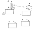
第1実施例である無線通信システム1Aは、図1に示すように、複数の通信機(子機)10と、該複数の通信機(子機)10とは別体に構成された通信端末20と、単独のアンテナ部31を有する通信機(親機)30を備えている。
第1実施例である無線通信システム1Aは、図1に示すように、複数の通信機(子機)10と、該複数の通信機(子機)10とは別体に構成された通信端末20と、単独のアンテナ部31を有する通信機(親機)30を備えている。
通信機(子機)10は、図2に示すように、それぞれ、通信端末20と電気的に結合する結合部11と、電源部(バッテリ)12と、送受信信号を処理する信号処理部13とを有し、信号処理部13はCPU14とRF回路15(アンプを含む)とで構成されている。通信機(親機)30は図示しないが子機10と同様の信号処理部や電源部を有している。
通信端末20は、電源部及び信号処理部を含むことはなく、前記子機10の結合部11と電気的に結合する結合部21と、電波を送受信するアンテナ部22と、結合部21とアンテナ部22とを接続する接続部23とを備えている。通信端末20はその結合部21が任意の子機10Aの結合部11と結合することにより、該子機10Aからその結合部21を介して信号を受信し、アンテナ部22から該信号を送信し、及び/又は、アンテナ部22で受信した信号を結合部21を介して該子機10Aに送信する。ここで、結合部11,21は、本実施例では磁界結合の場合を示しているが、容量結合、電界結合、電磁界結合又は直流結合であってもよい。なお、直流結合とは、直流的に接続されていることを意味する。
本無線通信システム1Aにあっては、通信端末20の結合部21と結合した子機10だけが親機30と通信が可能である。通信端末20は、例えばペンタイプであって例えば作業者によって把持され、任意の子機10に人手によって結合され、通信が終了すれば離間される。なお、結合/離間をマニュピーレータなどを用いて自動的に行うようにしてもよい。複数の子機10が存在していても、通信端末20と結合した一部の子機10だけが通信可能であることから、親機30の処理能力に過大な負担をかけることがなく、子機10に対する通信品質が悪化することはない。また、子機10間の電波干渉による通信品質の劣化が防止される。さらに、通信端末20は、電源部及び信号処理部を含むことはないので、安価に作製することができる。
なお、子機10の電源部12はバッテリであっても他から供給されるものであってもよく、あるいは、親機30から送信される信号を電力として取り出してもよい。また、通信端末20は複数配置されており、複数の子機10が親機30と同時に通信可能であってもよい。通信信号の周波数は、HF帯であってもUHF帯であっても構わない。例えば、ZigBee,WiFi,Bluetooth(登録商標)などであってもよく、RFIDであってもよい。
(第2実施例、図3参照)
第2実施例である無線通信システム1Bは、図3に示すように、複数の通信機(子機)10と、該複数の通信機(子機)10とは別体に構成された通信端末20とを備えている。この無線通信システム1Bにおいて、通信機10は全て子機であり、通信端末20の結合部21が結合した特定の通信機10Aが親機として機能する。つまり、いずれの通信機10であっても親機となり、あるいは、子機となり得る。通信の形態は前記第1実施例で説明したとおりである。また、本第2実施例の作用効果も第1実施例と同様であり、特に、いずれの通信機10を親機として用いるかは任意である。
第2実施例である無線通信システム1Bは、図3に示すように、複数の通信機(子機)10と、該複数の通信機(子機)10とは別体に構成された通信端末20とを備えている。この無線通信システム1Bにおいて、通信機10は全て子機であり、通信端末20の結合部21が結合した特定の通信機10Aが親機として機能する。つまり、いずれの通信機10であっても親機となり、あるいは、子機となり得る。通信の形態は前記第1実施例で説明したとおりである。また、本第2実施例の作用効果も第1実施例と同様であり、特に、いずれの通信機10を親機として用いるかは任意である。
他の使用例として、通信端末20を任意の二つの通信機10に結合させることで、該二つの通信機10を互いに通信可能としてもよい。
(第3実施例、図4~図6参照)
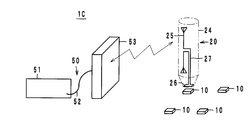
第3実施例である無線通信システム1Cは、図4に示すように、センサーネットワークシステムに応用したものであり、無線通信機(親機)50と、複数の通信機(子機)10と、通信端末20とで構成されている。無線通信機(親機)50は、信号処理回路などを含む本体51と、該本体51と信号線52で接続された電界型アンテナ53とを備えている。
第3実施例である無線通信システム1Cは、図4に示すように、センサーネットワークシステムに応用したものであり、無線通信機(親機)50と、複数の通信機(子機)10と、通信端末20とで構成されている。無線通信機(親機)50は、信号処理回路などを含む本体51と、該本体51と信号線52で接続された電界型アンテナ53とを備えている。
通信端末20は、例えばペン型の中継器として機能するものであり、第1アンテナ部25と、第2アンテナ部26(前記結合部21に相当する)と、この両者を電気的に接続する接続部27とを備え、これらの部品は筒状の筺体24に収容され、第2アンテナ部26は筺体24の先端部に配置されている。第1アンテナ部25は、電界型のダイポールアンテナであり、無線通信機(親機)50のアンテナ53と電界によって結合する。第2アンテナ部26は、磁界型のループアンテナであり、通信機10の結合部11(図2参照)と磁界によって結合する。第2アンテナ部26は結合部11とほぼ等しい面積のループ形状をなしている。それぞれの通信機10は、クロック回路、ロジック回路、メモリ回路などを含み、必要な情報がメモリされている。
この無線通信システム1Cにおいて、無線通信機(親機)50のアンテナ53から放射された高周波(HF帯、UHF帯あるいはそれ以上の高周波数帯)が通信端末20の第1アンテナ部25で受信され、接続部27を介して第2アンテナ部26に伝達される。そして、筺体24の先端部に配置された第2アンテナ部26を任意の通信機10に近接させることによって、第2アンテナ部26から放射された所定周波数の信号に基づく磁束が通信機10の結合部11を貫通することにより、該結合部11に電流が流れる。即ち、第2アンテナ部26と結合部11とが電磁結合する。この電流が通信機10のRF回路15(図2参照)に供給される。
一方、RF回路15からの応答信号が結合部11から第2アンテナ部26に放射され、その信号は接続部27を介して第1アンテナ部25に供給され、無線通信機(親機)50のアンテナ53で受信されて本体51で読み取られる。
本第3実施例において、第1アンテナ部25及び第2アンテナ部26はそれぞれ例えばZigBeeを子機としたセンサーネットワークシステムのような無線通信システムで使用する信号を扱うものであり、通信端末20が無線通信機(親機)50と通信機10との間を仲介するため、無線通信機(親機)50と通信機10とがそれのみでは通信不能な離れた距離に配置されていても通信が可能になる。特に、無線通信機(親機)50のアンテナ53と通信端末20の第1アンテナ部25とが電界によって結合するため、比較的長い距離での通信が可能である。しかも、無線通信機(親機)50のアンテナ53は既存の電界型を使用できる。また、通信機10の結合部11と第2アンテナ部26とは磁界によって結合するため、磁界は電界よりも減衰が大きく、近距離で通信が行われることになり、複数の通信機10が存在していても特定の通信機10を確実に読み取ることが可能である。また、通信端末20が無線通信機(親機)50と無線で結合しているため、複数の通信端末20を用いて複数の通信機10を同時に読み取ることもできる(図5参照)。
第1アンテナ部25と第2アンテナ部26との接続は、接続部27によって直流接続されており、効率よく信号を伝達することができる。但し、両者の接続は電磁界結合のような無線接続であってもよい。また、通信端末20はアンテナ部25,26と接続部27にて構成されており、バッテリのような駆動用電源やその周辺回路を必要とせず、小型・安価にできる。さらに、筐体24の先端部に第2アンテナ部26を配置しているため、第1アンテナ部25と第2アンテナ部26とを結合させることが容易である。
通信端末20は例えばペンタイプであり、指先で保持すると、人体も電界と結合するアンテナとして機能することがある。従って、第1アンテナ部25を指で握る部分に配置すると人体もアンテナとして作用し、第1アンテナ部25の感度が向上する。
図6に示すように、接続部27に(即ち、第2アンテナ部26と第1アンテナ部25との間に)、インダクタンスL1,L2とキャパシタンスCとからなる整合回路を設けてもよい。使用周波数でのインピーダンスの整合をとることができるので、第1アンテナ部25と第2アンテナ部26とのエネルギー伝達効率が向上し、小さな電力でも通信距離を長くすることができる。なお、整合回路としては、図6に示すもの以外の回路構成であってもよい。
(通信端末の結合部の変形例、図7及び図8参照)
通信端末20の結合部(アンテナ部)21,26は、図7に示すように、2重に螺旋状に巻回されていてもよい。磁束密度が大きくなり、通信性能が向上する。
通信端末20の結合部(アンテナ部)21,26は、図7に示すように、2重に螺旋状に巻回されていてもよい。磁束密度が大きくなり、通信性能が向上する。
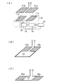
また、結合部21,26は、ループ形状ではなく、図8(A)に示すように、二つの平板状部41a,41bを備えた容量結合又は電界結合のアンテナとして機能するものであってもよい。この場合、通信機10の結合部11も二つの平板状部11a,11bを備えていることが好ましい。
通信端末20の結合部21,26は、図8(B),(C)に示すように、二つの平板状部42a,42bを線路43で接続したものであってもよい。
(他の実施例)
なお、本発明に係る無線通信システムは前記実施例に限定するものではなく、その要旨の範囲内で種々に変更できることは勿論である。
なお、本発明に係る無線通信システムは前記実施例に限定するものではなく、その要旨の範囲内で種々に変更できることは勿論である。
以上のように、本発明は、無線通信システムに有用であり、特に、親機から複数の子機に対する通信を確実に行える点で優れている。
1A,1B,1C…無線通信システム
10…通信機(子機)
11…結合部
12…電源部
13…信号処理部
20…通信端末
21…結合部
22…アンテナ部
25…第1アンテナ部
26…第2アンテナ部(結合部)
30…通信機(親機)
31…アンテナ部
10…通信機(子機)
11…結合部
12…電源部
13…信号処理部
20…通信端末
21…結合部
22…アンテナ部
25…第1アンテナ部
26…第2アンテナ部(結合部)
30…通信機(親機)
31…アンテナ部
Claims (5)
- 複数の通信機と、該複数の通信機とは別体に構成された通信端末とを備えた通信システムであって、
前記通信機は、それぞれ、前記通信端末と電気的に結合する結合部と、電源部と、送受信信号を処理する信号処理部とを有し、
前記通信端末は、電源部及び信号処理部を含むことはなく、前記通信機の結合部と電気的に結合する結合部と、電波を送受信するアンテナ部と、該結合部と該アンテナ部とを接続する接続部とからなり、
前記通信端末はその結合部が前記通信機の結合部と結合することにより、該通信機から該結合部を介して信号を受信し、そのアンテナ部から該信号を送信し、及び/又は、そのアンテナ部で受信した信号を該結合部を介して該通信機に送信すること、
を特徴とする無線通信システム。 - 前記通信端末の結合部と前記通信機の結合部とは、磁界結合、容量結合、電界結合、電磁界結合又は直流結合すること、を特徴とする請求項1に記載の無線通信システム。
- 前記通信端末の接続部は整合回路を有していること、を特徴とする請求項1又は請求項2に記載の無線通信システム。
- 前記複数の通信機は子機であって、単独のアンテナ部を有し、該アンテナ部によって前記通信端末の結合部が結合した一の通信機と通信が可能である親機を有すること、を特徴とする請求項1ないし請求項3のいずれかに記載の無線通信システム。
- 前記通信端末の結合部が結合した少なくとも二つの通信機が互いに通信可能であること、を特徴とする請求項1ないし請求項3のいずれかに記載の無線通信システム。
Priority Applications (2)
| Application Number | Priority Date | Filing Date | Title |
|---|---|---|---|
| JP2012555945A JP5641063B2 (ja) | 2011-02-04 | 2012-02-02 | 無線通信システム |
| US13/908,139 US9161160B2 (en) | 2011-02-04 | 2013-06-03 | Wireless communication system |
Applications Claiming Priority (2)
| Application Number | Priority Date | Filing Date | Title |
|---|---|---|---|
| JP2011-022668 | 2011-02-04 | ||
| JP2011022668 | 2011-02-04 |
Related Child Applications (1)
| Application Number | Title | Priority Date | Filing Date |
|---|---|---|---|
| US13/908,139 Continuation US9161160B2 (en) | 2011-02-04 | 2013-06-03 | Wireless communication system |
Publications (1)
| Publication Number | Publication Date |
|---|---|
| WO2012105634A1 true WO2012105634A1 (ja) | 2012-08-09 |
Family
ID=46602840
Family Applications (1)
| Application Number | Title | Priority Date | Filing Date |
|---|---|---|---|
| PCT/JP2012/052335 Ceased WO2012105634A1 (ja) | 2011-02-04 | 2012-02-02 | 無線通信システム |
Country Status (3)
| Country | Link |
|---|---|
| US (1) | US9161160B2 (ja) |
| JP (1) | JP5641063B2 (ja) |
| WO (1) | WO2012105634A1 (ja) |
Cited By (2)
| Publication number | Priority date | Publication date | Assignee | Title |
|---|---|---|---|---|
| WO2015149232A1 (zh) * | 2014-03-31 | 2015-10-08 | 华为终端有限公司 | 用户设备接入无线保真Wi-Fi的方法及Wi-Fi接入节点 |
| JP2018148551A (ja) * | 2017-03-01 | 2018-09-20 | エーケージー アコースティックス ゲーエムベーハー | ビバルディアンテナベースのアンテナシステム |
Families Citing this family (5)
| Publication number | Priority date | Publication date | Assignee | Title |
|---|---|---|---|---|
| SG11201400409XA (en) * | 2011-09-07 | 2014-04-28 | Solace Power Inc | Wireless electric field power transmission system and method |
| CA2953621A1 (en) | 2014-06-26 | 2015-12-30 | Solace Power Inc. | Wireless electric field power transmission system, transmitter and receiver therefor and method of wirelessly transferring power |
| WO2016033697A1 (en) | 2014-09-05 | 2016-03-10 | Solace Power Inc. | Wireless electric field power transfer system, method, transmitter and receiver therefor |
| KR102426701B1 (ko) * | 2015-12-16 | 2022-07-29 | 삼성전자주식회사 | 전자 장치 및 그의 동작 방법 |
| US11296750B2 (en) * | 2020-05-12 | 2022-04-05 | Nxp B.V. | Near-field wireless device including a first near-field antenna and a second near-field antenna |
Citations (4)
| Publication number | Priority date | Publication date | Assignee | Title |
|---|---|---|---|---|
| JPH08265250A (ja) * | 1995-01-27 | 1996-10-11 | Nec Corp | 移動体衛星通信装置 |
| JPH10145276A (ja) * | 1996-11-07 | 1998-05-29 | Nec Corp | アドホックネットワークシステムとその接続方法 |
| JP2003205791A (ja) * | 2002-01-15 | 2003-07-22 | Kojima Press Co Ltd | 車載機器用アンテナ装置 |
| JP2006245657A (ja) * | 2005-02-28 | 2006-09-14 | Toshiba Corp | 無線通信装置及び非接触式icカードリーダライタ装置 |
Family Cites Families (19)
| Publication number | Priority date | Publication date | Assignee | Title |
|---|---|---|---|---|
| NO960329L (no) | 1995-01-27 | 1996-07-29 | Nec Corp | Mobil satelitt-komunikasjonsterminal |
| US6026303A (en) | 1996-11-07 | 2000-02-15 | Nec Corporation | Method for determining optimal parent terminal and ad hoc network system for the same |
| JP2001103570A (ja) | 1999-09-30 | 2001-04-13 | Toshiba Corp | 通信システム、この通信システムに用いられる通信装置及び通信方法 |
| KR100713752B1 (ko) | 2005-02-28 | 2007-05-07 | 가부시끼가이샤 도시바 | 무선 통신 장치, 무선 통신 방법, 및 비접촉식 ic 카드리더 라이터 장치 |
| JP4639857B2 (ja) | 2005-03-07 | 2011-02-23 | 富士ゼロックス株式会社 | Rfidタグが取り付けられた物品を収納する収納箱、その配置方法、通信方法、通信確認方法および包装構造。 |
| JP2006301827A (ja) * | 2005-04-19 | 2006-11-02 | Aruze Corp | 非接触icカードシステム、並びに非接触icカードの取付体 |
| JP2007194842A (ja) * | 2006-01-18 | 2007-08-02 | Fujitsu Component Ltd | 通信装置 |
| JP2007221366A (ja) * | 2006-02-15 | 2007-08-30 | Matsushita Electric Ind Co Ltd | 接続ケーブルおよび携帯端末 |
| FR2910746B1 (fr) * | 2006-12-20 | 2009-01-23 | Smart Packaging Solutions Sps | Interface de communication radiofrequence locale entre un telephone mobile et un lecteur sans contact |
| JP2008167190A (ja) * | 2006-12-28 | 2008-07-17 | Philtech Inc | 基体シート |
| JP2008207875A (ja) * | 2007-01-30 | 2008-09-11 | Sony Corp | 光ディスクケース、光ディスクトレイ、カード部材、および製造方法 |
| JP5065780B2 (ja) | 2007-07-03 | 2012-11-07 | 株式会社日立製作所 | Rfidタグ実装基板 |
| US8878674B2 (en) * | 2007-10-04 | 2014-11-04 | Ncr Corporation | Item checkout device with antenna |
| JP4189433B1 (ja) * | 2007-10-18 | 2008-12-03 | パナソニック株式会社 | 携帯無線機 |
| WO2009050662A1 (en) * | 2007-10-19 | 2009-04-23 | Petratec International Ltd. | Rfid tag especially for use near conductive objects |
| JP2009231868A (ja) * | 2008-03-19 | 2009-10-08 | Nec Corp | 携帯端末、通信システム、および携帯端末の制御方法 |
| CN102576930A (zh) * | 2009-11-04 | 2012-07-11 | 株式会社村田制作所 | 通信终端及信息处理系统 |
| JP2013197852A (ja) * | 2012-03-19 | 2013-09-30 | Panasonic Corp | 携帯無線端末用ケース |
| US8922346B2 (en) * | 2012-07-16 | 2014-12-30 | Eastman Kodak Company | Masked container RFID tag communications system |
-
2012
- 2012-02-02 WO PCT/JP2012/052335 patent/WO2012105634A1/ja not_active Ceased
- 2012-02-02 JP JP2012555945A patent/JP5641063B2/ja not_active Expired - Fee Related
-
2013
- 2013-06-03 US US13/908,139 patent/US9161160B2/en not_active Expired - Fee Related
Patent Citations (4)
| Publication number | Priority date | Publication date | Assignee | Title |
|---|---|---|---|---|
| JPH08265250A (ja) * | 1995-01-27 | 1996-10-11 | Nec Corp | 移動体衛星通信装置 |
| JPH10145276A (ja) * | 1996-11-07 | 1998-05-29 | Nec Corp | アドホックネットワークシステムとその接続方法 |
| JP2003205791A (ja) * | 2002-01-15 | 2003-07-22 | Kojima Press Co Ltd | 車載機器用アンテナ装置 |
| JP2006245657A (ja) * | 2005-02-28 | 2006-09-14 | Toshiba Corp | 無線通信装置及び非接触式icカードリーダライタ装置 |
Cited By (3)
| Publication number | Priority date | Publication date | Assignee | Title |
|---|---|---|---|---|
| WO2015149232A1 (zh) * | 2014-03-31 | 2015-10-08 | 华为终端有限公司 | 用户设备接入无线保真Wi-Fi的方法及Wi-Fi接入节点 |
| JP2018148551A (ja) * | 2017-03-01 | 2018-09-20 | エーケージー アコースティックス ゲーエムベーハー | ビバルディアンテナベースのアンテナシステム |
| JP7067949B2 (ja) | 2017-03-01 | 2022-05-16 | エーケージー アコースティックス ゲーエムベーハー | ビバルディアンテナベースのアンテナシステム |
Also Published As
| Publication number | Publication date |
|---|---|
| JPWO2012105634A1 (ja) | 2014-07-03 |
| US20130260803A1 (en) | 2013-10-03 |
| JP5641063B2 (ja) | 2014-12-17 |
| US9161160B2 (en) | 2015-10-13 |
Similar Documents
| Publication | Publication Date | Title |
|---|---|---|
| JP5641063B2 (ja) | 無線通信システム | |
| US9166276B2 (en) | Multifunction single antenna for contactless systems | |
| TWI726854B (zh) | 行動電話可操作的詢答器標籤,可攜式物件,行動電話及相應方法 | |
| CN104704585B (zh) | 用于电能采集和/或无线通信的装置和方法 | |
| CN107749760B (zh) | 共享天线的设备、方法和装置 | |
| JP5187071B2 (ja) | 高周波電界結合器並びに結合用電極 | |
| US9362778B2 (en) | Short distance wireless device charging system having a shared antenna | |
| US8724835B2 (en) | Radio receiver, radio transmitter, and hearing aid | |
| CN101288236A (zh) | 借助通信的功率传输系统、设备和方法 | |
| JP5333601B2 (ja) | 通信端末及び情報処理システム | |
| WO2011055703A1 (ja) | 通信端末及び情報処理システム | |
| US11038553B2 (en) | EMC inductor-free RF front-end method and topology with power by field function for an inductively coupled communication system | |
| JP4060854B2 (ja) | 移動体識別装置の質問器 | |
| US9985693B2 (en) | Integrated circuit including multiple transmitters and near field communication system including the circuit | |
| CN202275455U (zh) | 微型uhf rfid读写与nfc移动支付一体化模块 | |
| US9876276B2 (en) | Device with radio and body-coupled-communication connectivity | |
| CN109309516B (zh) | 用于近场通信应答器设备中的有源负载调制的天线设计 | |
| US11184052B2 (en) | Apparatus and method with near-field communication | |
| US20180131412A1 (en) | Methods for increasing data communication bandwidth between wireless power devices | |
| CN102130472A (zh) | 移动装置的电池模块和传收模块 | |
| CN207234767U (zh) | 一种近场通信nfc电路和终端 | |
| TWI408988B (zh) | 行動裝置的電池模組和傳收模組 | |
| KR20160043900A (ko) | 코일 구조체 및 그를 이용한 무선 전력 수신 장치 | |
| JPWO2018139519A1 (ja) | アンテナ装置、非接触伝送装置および非接触伝送システム | |
| WO2025161326A1 (zh) | 价签基站 |
Legal Events
| Date | Code | Title | Description |
|---|---|---|---|
| 121 | Ep: the epo has been informed by wipo that ep was designated in this application |
Ref document number: 12742029 Country of ref document: EP Kind code of ref document: A1 |
|
| ENP | Entry into the national phase |
Ref document number: 2012555945 Country of ref document: JP Kind code of ref document: A |
|
| NENP | Non-entry into the national phase |
Ref country code: DE |
|
| 122 | Ep: pct application non-entry in european phase |
Ref document number: 12742029 Country of ref document: EP Kind code of ref document: A1 |