WO2012105419A1 - 封口用マスク設計プログラム及び封口用マスク設計方法 - Google Patents
封口用マスク設計プログラム及び封口用マスク設計方法 Download PDFInfo
- Publication number
- WO2012105419A1 WO2012105419A1 PCT/JP2012/051719 JP2012051719W WO2012105419A1 WO 2012105419 A1 WO2012105419 A1 WO 2012105419A1 JP 2012051719 W JP2012051719 W JP 2012051719W WO 2012105419 A1 WO2012105419 A1 WO 2012105419A1
- Authority
- WO
- WIPO (PCT)
- Prior art keywords
- mask
- sealing
- designed
- cell
- hole
- Prior art date
- Legal status (The legal status is an assumption and is not a legal conclusion. Google has not performed a legal analysis and makes no representation as to the accuracy of the status listed.)
- Ceased
Links
Images




Classifications
-
- B—PERFORMING OPERATIONS; TRANSPORTING
- B28—WORKING CEMENT, CLAY, OR STONE
- B28B—SHAPING CLAY OR OTHER CERAMIC COMPOSITIONS; SHAPING SLAG; SHAPING MIXTURES CONTAINING CEMENTITIOUS MATERIAL, e.g. PLASTER
- B28B11/00—Apparatus or processes for treating or working the shaped or preshaped articles
- B28B11/003—Apparatus or processes for treating or working the shaped or preshaped articles the shaping of preshaped articles, e.g. by bending
- B28B11/006—Making hollow articles or partly closed articles
- B28B11/007—Using a mask for plugging
Definitions
- One embodiment of the present invention relates to a sealing mask design program and a sealing mask design method, and includes a through hole corresponding to a cell to seal a cell which is a plurality of through holes opened at an end of a honeycomb structure.
- the present invention relates to a sealing mask design program and a sealing mask design method for designing a sealing mask in which a certain mask hole is formed.
- honeycomb filter structures have been widely known for DPF (Diesel particulate filter) and the like.
- This honeycomb filter structure has a structure in which one end side of a part of cells of a cell structure including a large number of through holes is sealed with a sealing material, and the other end side of the remaining cells is sealed with a sealing material.
- a mask is used to seal a predetermined cell among many cells of the honeycomb structure.
- Patent Documents 1 and 2 describe a method for sealing a honeycomb structure using a mask.
- the mask of the type in which the through holes are provided in advance needs to be aligned with the honeycomb structure.
- a sintered body manufactured through a drying process or a firing process such as a DPF
- the honeycomb structure is sealed with a mask through-hole due to shrinkage or deformation of the honeycomb structure in the manufacturing process.
- the alignment with the power cell becomes even more difficult.
- Some DPFs have a narrow cell pitch (for example, about 0.8 to 2.5 mm), and even if the through-holes of the mask can be appropriately arranged on a part of the end face of the honeycomb structure, the other parts are not displaced. It may occur.
- One embodiment of the present invention has been made in view of the above problems, and can be easily aligned with the end face of the honeycomb structure, and a mask that is useful for reliably sealing a predetermined cell is designed. It is an object of the present invention to provide a sealing mask design program and a sealing mask design method that can be performed.
- One embodiment of the present invention designs a sealing mask in which a mask hole that is a through hole corresponding to a cell is formed in order to seal a cell that is a plurality of through holes that are open at an end of the honeycomb structure.
- a sealing position design process for detecting a position of each cell to be sealed based on an image of an end of a honeycomb structure sealed by a sealing mask to be designed, and a cell position detection process
- a mask hole position determination step for determining the position of the mask hole of the sealing mask to be designed based on the position of each cell detected in step (b).
- a sealing mask having a mask hole which is a through-hole corresponding to the cell is designed.
- the sealing mask design program is detected in the cell position detection step for detecting the position of each cell to be sealed based on the image of the end of the honeycomb structure sealed by the sealing mask to be designed, and the cell position detection step.
- the information processing apparatus is caused to execute a mask hole position determining step for determining the position of the mask hole of the sealing mask to be designed.
- the position of the mask hole is determined based on the actual image of the honeycomb structure sealed by the sealing mask to be designed, and the alignment with each cell of the honeycomb structure can be easily performed. It is possible to design a mask useful for reliably sealing a predetermined cell.
- the information processing apparatus is further caused to execute a mask hole size determining step for determining the size of the mask hole of the sealing mask to be designed based on the image of the end portion of the honeycomb structure sealed by the sealing mask to be designed. be able to.
- the sealing mask design program determines the size of the mask hole of the sealing mask to be designed based on the image of the end of the honeycomb structure sealed by the sealing mask to be designed.
- the information processing apparatus is further caused to execute the determination step. For this reason, the size of the mask hole is determined based on the actual image of the honeycomb structure sealed by the sealing mask to be designed, and a mask useful for sealing a predetermined cell reliably is designed. can do.
- the size of each cell to be sealed is detected based on the image of the end portion of the honeycomb structure sealed by the sealing mask to be designed, and the design is made more than the size of each cell to be sealed. It is possible to cause the information processing apparatus to execute a mask hole size determining step for determining the size of the mask hole so that the size of each mask hole of the sealing mask is reduced.
- the mask hole size determining step the size of each cell to be sealed is detected based on the image of the end of the honeycomb structure sealed by the sealing mask to be designed, and the size of each cell to be sealed is determined.
- the information processing apparatus is caused to execute a mask hole size determining step for determining the size of the mask hole so that the size of each mask hole of the sealing mask to be designed becomes smaller. Therefore, the mask hole of the sealing mask to be designed can be accurately designed to have a size suitable for sealing with respect to the cell size of the actual honeycomb structure to be sealed.
- the information processing apparatus executes a cell position detection step of detecting the center position of each cell to be sealed,
- the center position of each cell detected in the cell position detection step matches the center position of each mask hole of the sealing mask to be designed so that the mask hole of the sealing mask to be designed matches. It is possible to cause the information processing apparatus to execute a mask hole position determining step for determining the position.
- the cell position detection step for detecting the center position of each cell to be sealed based on the image of the end portion of the honeycomb structure sealed by the sealing mask to be designed is the information processing device.
- the sealing mask to be designed is designed so that the center position of each cell detected in the cell position detection step matches the center position of each mask hole of the sealing mask to be designed.
- the information processing apparatus is caused to execute a mask hole position determining step for determining the position of the mask hole.
- an embodiment of the present invention provides a sealing mask in which a mask hole which is a through hole corresponding to a cell is formed in order to seal a cell which is a plurality of through holes opened at an end of the honeycomb structure.
- a sealing mask designing method for designing a cell position detecting step for detecting the position of each cell to be sealed based on an image of an end of a honeycomb structure sealed by the sealing mask to be designed, and a cell position detecting step
- a mask hole position determining step for determining the position of the mask hole of the sealing mask to be designed based on the position of each cell detected in (1).
- it may further include a mask hole size determining step for determining the size of the mask hole of the sealing mask to be designed based on the image of the end portion of the honeycomb structure sealed by the sealing mask to be designed.
- the size of each cell to be sealed is detected based on the image of the end portion of the honeycomb structure sealed by the sealing mask to be designed, and the design is made more than the size of each cell to be sealed.
- the size of the mask hole can be determined so that the size of each mask hole of the sealing mask to be reduced is reduced.
- the center position of each cell to be sealed is detected based on the image of the end of the honeycomb structure sealed by the sealing mask to be designed.
- the cell position detection step The position of the mask hole of the sealing mask to be designed can be determined so that the center position of each of the cells detected in step 1 matches the center position of each mask hole of the sealing mask to be designed.
- a mask useful for sealing a predetermined cell can be designed.
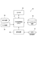
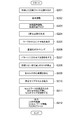
- FIG. 1 shows the hardware constitutions of the information processing apparatus with which the design method of the mask for sealing concerning embodiment of this invention is performed. It is a flowchart which shows the outline of the design method of the mask for sealing concerning embodiment of this invention.
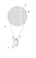
- A) is a perspective view of a honeycomb structure, (b) is the elements on larger scale of (a).
- (A) is a perspective view of the mask for sealing, (b) is the elements on larger scale of (a).
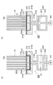
- (A) is sectional drawing which shows a sealing apparatus, (b) is sectional drawing following (a) which shows operation
- FIG. 10A is a diagram illustrating a state in which cells having an excessively large size are pasted
- FIG. 10B is a diagram illustrating a state in which cells having an appropriate size are pasted. It is a figure which shows the state which affixed the cell of an appropriate size about each through-hole of the image of FIG. It is a figure which shows the image of the designed mask for sealing.
- an information processing apparatus such as a workstation or a PC (Personal Computer).
- an information processing apparatus 30 includes a central processing unit (CPU) 31, a hard disk device 32 for storing programs and data, a main memory 33, and inputs such as a keyboard and a mouse.
- the apparatus 34 includes a display device 35 such as a CRT (Cathode Ray Tube), and a reading device 36 that reads a recording medium 37 such as a magnetic tape or a ROM.
- the hard disk device 32, the main memory 33, the input device 34, the display device 35, and the reading device 36 are all connected to the central processing unit 31.
- a recording medium 37 storing a program is loaded in the reading device 36, and the program is read from the recording medium 37 and stored in the hard disk device 32.
- the program stored in the hard disk device 32 is developed and executed on the main memory 33 by the central processing unit 31, and the sealing mask design method according to the present embodiment is executed.
- the sealing mask design method according to the present embodiment may be executed only by the apparatus, not by the program as described above. All of the series of processes described below may be executed by the information processing apparatus, or a part of the series of processes may be executed by the information processing apparatus.
- an end portion where a cell is opened is photographed in a honeycomb structure for DPF or the like serving as a workpiece, and a scan image of the end portion is acquired.
- the sealing mask design program of the present embodiment causes the information processing apparatus 30 to read the scanned image of the honeycomb structure (S10).
- An example honeycomb structure 70 that is a workpiece in the present embodiment is a cylindrical body in which a large number of through holes (cells) 70a are arranged substantially in parallel as shown in FIG.
- the cross-sectional shape of the through hole 70a is a square as shown in FIG.
- the plurality of through holes 70a are arranged in a square arrangement in the honeycomb structure 70, that is, such that the central axis of the through hole 70a is located at the apex of the square, respectively.
- the square size of the cross section of the through hole 70a can be set to, for example, 0.8 to 2.5 mm on a side.
- the length of the honeycomb structure 70 in the direction in which the through holes 70a extend is not particularly limited, but may be 40 to 350 mm, for example.
- the outer diameter of the honeycomb structure 70 is not particularly limited, but may be, for example, 10 to 320 mm.
- the material of the honeycomb structure 70 is not particularly limited, but may be a ceramic material from the viewpoint of high temperature resistance. Examples thereof include alumina, silica, mullite, cordierite, glass, oxides such as aluminum titanate, silicon carbide, silicon nitride, and metal.
- the aluminum titanate can further contain at least one of magnesium and silicon.
- Such a honeycomb structure 70 is usually porous.
- the honeycomb structure 70 can be green (unfired body) that becomes porous ceramics by firing, and in this case, can be a formed body of ceramic source powder.
- the ceramic is not particularly limited, and examples thereof include alumina, silica, mullite, cordierite, glass, oxides such as aluminum titanate, silicon carbide, silicon nitride, and metal.
- the aluminum titanate can further contain magnesium and / or silicon.
- the green molded body includes an inorganic compound source powder that is a ceramic source powder, an organic binder such as methylcellulose, and an additive that is added as necessary.
- the inorganic compound source powder includes an aluminum source powder such as ⁇ -alumina powder, and a titanium source powder such as anatase type or rutile type titania powder. Furthermore, at least one of magnesium source powder such as magnesia powder and magnesia spinel powder and silicon source powder such as silicon oxide powder and glass frit can be included.
- organic binder examples include celluloses such as methylcellulose, carboxymethylcellulose, hydroxyalkylmethylcellulose, and sodium carboxymethylcellulose; alcohols such as polyvinyl alcohol; and lignin sulfonate.
- the additive include a pore-forming agent, a lubricant and a plasticizer, a dispersant, and a solvent.
- the sealing mask design program of the present embodiment causes the information processing apparatus 30 to execute the sealing mask design method described in detail below (S20).
- the sealing mask design program of the present embodiment causes the information processing apparatus 30 to output a processing drawing of the designed sealing mask (S30).
- FIG. 4A shows an example of the mask 170 manufactured based on the design by the sealing mask design method of the present embodiment.
- the mask 170 is a circular plate-like member, and has a large number of through holes (mask holes) 170a extending in the thickness direction.
- the cross-sectional shape of the through hole 170a is a square corresponding to the through hole 70a (see FIG. 3B) of the honeycomb structure 70, as shown in FIG. 4B.
- the plurality of through holes 170a are arranged in a staggered manner as shown in FIG. 4B, and each through hole 170a is formed of the plurality of through holes 70a arranged in a square shape in FIG. 3B.
- the mask 170 can be, for example, a metal mask manufactured from metal.
- the sealing of the cells 70a of the honeycomb structure 70 is performed using the sealing device 200 as shown in FIGS. 5A and 5B using the mask 170 as described above.
- the sealing device 200 according to the present embodiment mainly includes a main body 210, an elastic plate 220, and a pump 250.
- the main body 210 is a rigid member formed of a metal (for example, stainless steel) or a polymer material (for example, fiber reinforced plastic).
- a recess 210d is formed in the main body 210, and a porous member 210p is attached to the inner surface of the recess 210d.
- the elastic plate 220 is disposed on the main body 210 so as to cover the opening surface of the recess 210d.
- the elastic plate 220 has elasticity and can be easily deformed.
- the elastic plate 220 can be a rubber plate.
- the elastic plate 220 is fixed to the main body 210 by a ring member 225.
- the ring member 225 has an opening 225a at a position corresponding to the recess 210d of the main body 210, thereby forming an annular shape.
- the ring member 225 is arrange
- the main body 210 further has a communication path 210e communicating with the porous member 210p on the bottom surface of the recess 210d.
- a pump 250 is connected to the communication path 210e.
- the pump 250 includes a cylinder 251 and a piston 253 disposed in the cylinder 251.
- a motor 255 that reciprocates the piston 253 in the axial direction is connected to the piston 253.
- a closed space V formed by the main body 210, the communication path 210e and the cylinder 251 is formed between the elastic plate 220 and the piston 253, and a fluid FL such as gas or liquid is formed in the closed space V. Filled.
- the fluid FL can be discharged from the recess 210d of the main body 210, and the elastic plate 220 can be brought into close contact with the inner surface of the recess 210d to form the recess 220d by the elastic plate 220 (FIG. 5 (a)), and the elastic plate 220 can be pulled away from the bottom of the recess 210d (state (b) of FIG. 5) to supply the fluid FL into the recess 210d.
- the piston 253 is lowered to form a recess 220d by the elastic plate 220, and the sealing paste P manufactured as described above is stored in the recess 220d. deep.
- a sealing mask 170 is disposed on the recess 210d of the main body 210.
- the mask hole 170a of the sealing mask 170 is positioned by the above-described orientation flat b with respect to the honeycomb structure 70 so as to face only the hole to be sealed among the cells 70a of the ceramic honeycomb structure 70.
- the fluid FL is supplied into the recess 210d by moving the piston 253 of the pump 250 upward, thereby moving the elastic plate 220 toward the mask 170.
- the sealing material P is supplied into a part of the through holes 70 a of the ceramic honeycomb structure 70 through the through holes 170 a of the mask 170, and the sealing portion 72 is formed.
- the piston 253 is further raised to further supply the fluid FL between the elastic plate 220 and the main body 210, and the elastic plate 220 is deformed in a convex shape upward, thereby forming a ceramic honeycomb structure.
- the body 70 and the mask 170 are separated from the elastic plate 220.
- the direction of the honeycomb structure is reversed up and down by a reversing device (not shown), and similarly, the honeycomb structure 70 is placed on the other sealing portion 200, and the other surface of the ceramic honeycomb structure 70 is placed.
- a ceramic honeycomb filter can be manufactured by drying and firing the sealed ceramic honeycomb structure. Such a ceramic honeycomb filter can be used as, for example, a DPF.
- the sealing mask design program of the present embodiment causes the information processing apparatus 30 to read a scan image of the end face of the honeycomb structure 70 sealed by the mask 170 designed (S201).
- the scan image in this case can be a gray scale image of about 400 dpi (dot per inch), for example.
- the sealing mask design program causes the information processing apparatus 30 to set a reference such as XY coordinates for the work image 700 that is a scan image of the end face of the honeycomb structure 70 (S202). . Thereby, the position of the through-hole (cell) 700a in the work image 700 is specified by the XY coordinates.
- the sealing mask design program causes the information processing apparatus 30 to adjust the processing range, and places a portion other than the honeycomb structure 70 shown in the work image 700 outside the processing range and puts a black mask (S203).
- the sealing mask design program causes the information processing apparatus 30 to generate black and white binarized images of the work image 700 (S204).
- the binarization processing of the work image 700 is completed by the above processing of S201 to S204.
- the sealing mask design program causes the information processing apparatus 30 to display a crosshair Co at the center of the work image 700 of the honeycomb structure 70 (S205).
- the sealing mask design program causes the information processing apparatus 30 to assign an ID number to each through-hole 700a in the work image 700 and label the through-hole 700a (S206).
- the sealing mask design program causes the information processing apparatus 30 to perform the sealing of the sealing within the through hole 700 a in the work image 700 according to the pattern of the mask hole 170 a of the mask 170 to be designed.
- the through hole 700a that is not the target is whitened (S207).
- the sealing mask design program causes the information processing device 30 to correct the through-hole 700a that is unintentionally whitened and becomes a filled cell due to the influence of noise or the like (S208).
- the sealing mask design program causes the information processing apparatus 30 to pass through holes 700 a that are white cells that are not filled in the through holes 700 a in the work image 700. Is detected, and a crosshair Cc is displayed at the center coordinate (S209).
- the sealing mask design program pastes a cell 1700a of a predetermined size on the information processing apparatus 30 while aligning the center coordinates of the through-hole 700a and the center of the cell 1700a with respect to the through-hole 700a that has detected the center coordinate in the workpiece image 700. (S210).
- the sealing mask design program causes the information processing apparatus 30 to determine the matching state of the size of the cell 1700a and the through-hole 700a of the work image 700 and adjust the size of the cell 1700a (S211).
- a plurality of sizes of cells 1700a standardized for the mask 170 to be designed are prepared.
- the sealing material P is injected into the cells 70a of the honeycomb structure 70 that seals the sealing material P through the mask holes 170a of the mask 170 to be designed, the mask to be designed is larger than the size of the through hole 700a of the work image 700.
- the size of the 170 mask holes 170a needs to be small.
- the sealing mask design program causes the information processing apparatus 30 to match the size of the cell 1700a and the through hole 700a of the work image 700. The state is determined for each through-hole 700a. As shown in FIG. 11A, it is not appropriate when the cell 1700a of the mask 170 to be designed is larger than the through-hole 700a of the work image 700. On the other hand, as shown in FIG. 11B, when the cell 1700a of the mask 170 to be designed is smaller than the through-hole 700a of the work image 700, it is determined that it is suitable. As shown in FIGS. 6 and 12, the sealing mask design program causes the information processing apparatus 30 to execute the above-described processing for each of the through holes 700 a of the work image 700.
- the sealing mask design program designs a cell 1700a having a common size smaller than each of the through holes 700a in the work image 700 among the plurality of standardized cells 1700a in the information processing apparatus 30.
- the mask hole 170a of the mask 170 to be set can be set. In this case, the actual mask 170 can be easily manufactured.
- the sealing mask design program causes the information processing apparatus 30 to select the largest size cell 1700a among the cells 1700a having a size smaller than each of the through holes 700a among the plurality of standardized size cells 1700a. Can be set for each through-hole 700a in the workpiece image 700. In this case, the matching state between the cells 70a of the actual honeycomb structure 70 and the mask holes 170a of the mask 170 is good.
- the sealing mask design image 1700 provided with the cells 1700a in a predetermined sealing pattern as shown in FIG. 13 is obtained, and the design process is completed.
- the sealing mask design program performs post-processing on the information processing device 30 as post-processing sealing mask design image 1700, information about the cell 70a to be sealed, and the honeycomb structure 70 that is the workpiece, and their CSV (Comma Separated Values).
- the file is output (S212).
- a sealing mask in which mask holes 170a that are through holes corresponding to the cells 70a are formed in order to seal the cells 70a that are a plurality of through holes that are opened at the end of the honeycomb structure 70.
- the sealing mask design program for designing 170 is detected by detecting the position of each cell 70a to be sealed based on the image of the end of the honeycomb structure 70 sealed by the sealing mask 170 to be designed.
- the information processing apparatus 30 is caused to execute a step of determining the position of the mask hole 170a of the sealing mask 170 to be designed based on the position of each of the cells 70a.
- the position of the mask hole 170a is determined based on the actual image of the honeycomb structure 70 to be sealed by the sealing mask 170 to be designed, and the alignment with each cell 70a of the honeycomb structure 70 is performed. It is possible to design a mask 170 that can be easily performed and is useful for reliably sealing a predetermined cell 70a.
- the sealing mask design program creates a size of the mask hole 170a of the sealing mask 170 to be designed based on the image of the end portion of the honeycomb structure 70 sealed by the sealing mask 170 to be designed. Further, the information processing device 30 is caused to execute the process of determining the length. Therefore, the size of the mask hole 170a is determined based on the actual image of the honeycomb structure 70 to be sealed by the sealing mask 170 to be designed, which is useful for reliably sealing a predetermined cell 70a. Mask 170 can be designed.
- the size of each cell 70a to be sealed is detected based on the image of the end portion of the honeycomb structure 70 sealed by the sealing mask 170 to be designed, and the size of each cell 70a to be sealed is detected.
- the information processing apparatus 30 is caused to execute a step of determining the size of the mask hole 170a so that the size of each mask hole 170a of the sealing mask 170 to be designed becomes smaller. Therefore, the mask hole 170a of the sealing mask 170 to be designed can be accurately designed to have a size suitable for sealing with respect to the size of the cell 70a of the actual honeycomb structure 70 to be sealed. .
- the information processing device 30 executes a process of detecting the center position of each cell 70a to be sealed based on the image of the end of the honeycomb structure 70 to be sealed by the sealing mask 170 to be designed. And determining the position of the mask hole 170a of the sealing mask 170 to be designed so that the center position of each of the detected cells 70a matches the center position of the mask hole 170a of the sealing mask 170 to be designed. Is executed by the information processing apparatus 30. Since the center position of the cell 70a and the center position of the mask hole 170a coincide with each other, even if the distance between the cells 70a and the size of each cell 70a are not uniform, the size of the mask hole 170a is appropriately set. By designing the mask 170, it is possible to design the mask 170 that can reliably seal the cell 70a.
- a mask useful for sealing a predetermined cell can be designed.
- Information processing device 31 Central processing unit 32 Hard disk device 33 Main memory 34 Input device 35 Display device 36 Reading device 37 Recording medium 70 Honeycomb structure 70a Through hole 170 Sealing mask 170a Through hole 170b Mark 200 Sealing device 210 Main body part 210d Recessed part 210e Communication path 210p Porous member 220 Elastic plate 225 Ring member 225a Opening 250 Pump 251 Cylinder 253 Piston 255 Motor 700 Work image 700a Through-hole 1700 Sealing mask design image 1700a Cell
Landscapes
- Engineering & Computer Science (AREA)
- Structural Engineering (AREA)
- Chemical & Material Sciences (AREA)
- Ceramic Engineering (AREA)
- Mechanical Engineering (AREA)
- Devices For Post-Treatments, Processing, Supply, Discharge, And Other Processes (AREA)
- Filtering Materials (AREA)
Abstract
ハニカム構造体の端部に開口したセルを封口するために、セルに対応したマスク孔が形成された封口用マスクを設計する封口用マスク設計プログラムは、ハニカム構造体の端部の画像に基づいて封口するセルの位置を検出する工程と、セルの位置に基づいて封口用マスクのマスク孔の位置を決定する工程とを情報処理装置に実行させる。設計する封口用マスクが封口するハニカム構造体の実際の画像に基づいてマスク孔の位置が決定されることになり、ハニカム構造体のセルとの位置合わせを容易に行うことができ、セルを確実に封口するのに有用なマスクを設計できる。
Description
本発明の一実施形態は、封口用マスク設計プログラム及び封口用マスク設計方法に関し、ハニカム構造体の端部に開口した複数の貫通孔であるセルを封口するために、セルに対応した貫通孔であるマスク孔が形成された封口用マスクを設計するための封口用マスク設計プログラム及び封口用マスク設計方法に関する。
従来より、ハニカムフィルタ構造体が、DPF(Diesel particulate filter)用等として広く知られている。このハニカムフィルタ構造体は、多数の貫通孔からなるセル構造の一部のセルの一端側を封口材で封じると共に、残りのセルの他端側を封口材で封じた構造を有する。
ハニカム構造体の多数のセルのうち、所定のセルを封口するのにマスクが使用される。このような用途のマスクとして2つのタイプがある。一方は封口すべきセルに対応する箇所に予め貫通孔が設けられているタイプである。他方は貫通孔が予め設けられていないタイプであり、ハニカム構造体の端面に貼り付けた後に封口すべきセルに対応する箇所にレーザー等で貫通孔を設けるものである。下記特許文献1,2には、マスクを用いてハニカム構造体を封口する方法が記載されている。
ところで、予め貫通孔が設けられているタイプのマスクは、ハニカム構造体との位置合わせが必要である。ハニカム構造体がDPFのように、乾燥工程や焼成工程を経て製造される焼結体焼成前のグリーン成形体の場合、製造プロセスにおけるハニカム構造体の収縮や変形により、マスクの貫通孔と封口すべきセルとの位置合わせがより一層困難になる。DPFは、狭いセルピッチ(例えば0.8~2.5mm程度)を有するものもあり、ハニカム構造体の端面の一部についてはマスクの貫通孔を適切に配置できても、他の部分ではずれが生じる場合もある。
本発明の一実施形態は上記課題に鑑みてなされたものであり、ハニカム構造体の端面との位置合わせを容易に行うことができ、所定のセルを確実に封口するのに有用なマスクを設計することが可能な封口用マスク設計プログラム及び封口用マスク設計方法を提供することを目的とする。
本発明の一実施形態は、ハニカム構造体の端部に開口した複数の貫通孔であるセルを封口するために、セルに対応した貫通孔であるマスク孔が形成された封口用マスクを設計するための封口用マスク設計プログラムであって、設計する封口用マスクが封口するハニカム構造体の端部の画像に基づいて、封口するセルそれぞれの位置を検出するセル位置検出工程と、セル位置検出工程で検出されたセルそれぞれの位置に基づいて、設計する封口用マスクのマスク孔の位置を決定するマスク孔位置決定工程とを情報処理装置に実行させる封口用マスク設計プログラムである。
この構成によれば、ハニカム構造体の端部に開口した複数の貫通孔であるセルを封口するために、セルに対応した貫通孔であるマスク孔が形成された封口用マスクを設計するための封口用マスク設計プログラムは、設計する封口用マスクが封口するハニカム構造体の端部の画像に基づいて、封口するセルそれぞれの位置を検出するセル位置検出工程と、セル位置検出工程で検出されたセルそれぞれの位置に基づいて、設計する封口用マスクのマスク孔の位置を決定するマスク孔位置決定工程とを情報処理装置に実行させる。このため、設計する封口用マスクが封口するハニカム構造体の実際の画像に基づいて、マスク孔の位置が決定されることになり、ハニカム構造体のセルそれぞれとの位置合わせを容易に行うことができ、所定のセルを確実に封口するのに有用なマスクを設計することができる。
この場合、設計する封口用マスクが封口するハニカム構造体の端部の画像に基づいて、設計する封口用マスクのマスク孔の大きさを決定するマスク孔サイズ決定工程をさらに情報処理装置に実行させることができる。
この構成によれば、封口用マスク設計プログラムは、設計する封口用マスクが封口するハニカム構造体の端部の画像に基づいて、設計する封口用マスクのマスク孔の大きさを決定するマスク孔サイズ決定工程をさらに情報処理装置に実行させる。このため、設計する封口用マスクが封口するハニカム構造体の実際の画像に基づいて、マスク孔の大きさが決定されることになり、所定のセルを確実に封口するのに有用なマスクを設計することができる。
この場合、マスク孔サイズ決定工程では、設計する封口用マスクが封口するハニカム構造体の端部の画像に基づいて、封口するセルそれぞれの大きさを検出し、封口するセルそれぞれの大きさよりも設計する封口用マスクのマスク孔それぞれの大きさが小さくなるようにマスク孔の大きさを決定するマスク孔サイズ決定工程を情報処理装置に実行させることができる。
この構成によれば、マスク孔サイズ決定工程では、設計する封口用マスクが封口するハニカム構造体の端部の画像に基づいて、封口するセルそれぞれの大きさを検出し、封口するセルそれぞれの大きさよりも設計する封口用マスクのマスク孔それぞれの大きさが小さくなるようにマスク孔の大きさを決定するマスク孔サイズ決定工程を情報処理装置に実行させる。このため、設計する封口用マスクのマスク孔は、封口する実際のハニカム構造体のセルの大きさに対して封口することに適した大きさに正確に設計することが可能となる。
また、セル位置検出工程では、設計する封口用マスクが封口するハニカム構造体の端部の画像に基づいて、封口するセルそれぞれの中心位置を検出するセル位置検出工程を情報処理装置に実行させ、マスク孔位置決定工程では、セル位置検出工程で検出されたセルそれぞれの中心位置と、設計する封口用マスクのマスク孔それぞれの中心位置とが一致するように、設計する封口用マスクのマスク孔の位置を決定するマスク孔位置決定工程を情報処理装置に実行させることができる。
この構成によれば、セル位置検出工程では、設計する封口用マスクが封口するハニカム構造体の端部の画像に基づいて、封口するセルそれぞれの中心位置を検出するセル位置検出工程を情報処理装置に実行させ、マスク孔位置決定工程では、セル位置検出工程で検出されたセルそれぞれの中心位置と、設計する封口用マスクのマスク孔それぞれの中心位置とが一致するように、設計する封口用マスクのマスク孔の位置を決定するマスク孔位置決定工程を情報処理装置に実行させる。セルの中心位置とマスク孔の中心位置とが一致していることにより、セル同士の間隔やセルそれぞれの大きさが不均一であったとしても、マスク孔の大きさを適切に設計することにより、セルを確実に封口することができるマスクを設計することができる。
また、本発明の一実施形態は、ハニカム構造体の端部に開口した複数の貫通孔であるセルを封口するために、セルに対応した貫通孔であるマスク孔が形成された封口用マスクを設計する封口用マスク設計方法であって、設計する封口用マスクが封口するハニカム構造体の端部の画像に基づいて、封口するセルそれぞれの位置を検出するセル位置検出工程と、セル位置検出工程で検出されたセルそれぞれの位置に基づいて、設計する封口用マスクのマスク孔の位置を決定するマスク孔位置決定工程とを含む封口用マスク設計方法である。
この場合、設計する封口用マスクが封口するハニカム構造体の端部の画像に基づいて、設計する封口用マスクのマスク孔の大きさを決定するマスク孔サイズ決定工程をさらに含むことができる。
この場合、マスク孔サイズ決定工程では、設計する封口用マスクが封口するハニカム構造体の端部の画像に基づいて、封口するセルそれぞれの大きさを検出し、封口するセルそれぞれの大きさよりも設計する封口用マスクのマスク孔それぞれの大きさが小さくなるようにマスク孔の大きさを決定することができる。
また、セル位置検出工程では、設計する封口用マスクが封口するハニカム構造体の端部の画像に基づいて、封口するセルそれぞれの中心位置を検出し、マスク孔位置決定工程では、セル位置検出工程で検出されたセルそれぞれの中心位置と、設計する封口用マスクのマスク孔それぞれの中心位置とが一致するように、設計する封口用マスクのマスク孔の位置を決定することができる。
本発明の一実施形態の封口用マスク設計プログラム及び封口用マスク設計方法によれば、所定のセルを確実に封口するのに有用なマスクを設計することができる。
以下、図面を参照して本発明の実施形態に係る封口用マスク設計プログラム及び封口用マスク設計方法を説明する。
本実施形態に係る封口用マスク設計方法は、DPF用等のハニカム構造体の端部に開口した複数の貫通孔であるセルを封口するために、予めセルに対応した貫通孔であるマスク孔が形成された封口用マスクを設計するものであって、ワークステーションやPC(Personal Computer)等の情報処理装置により実行される。情報処理装置30としては、例えば、図1に示すようなハードウェア構成のものが用いられる。図1に示すように、情報処理装置30は、中央処理装置(Central Processing Unit:CPU)31と、プログラムやデータを格納するためのハードディスク装置32と、主メモリ33と、キーボードやマウス等の入力装置34と、CRT(Cathode Ray Tube)等の表示装置35と、磁気テープやROM等の記録媒体37を読み取る読取装置36とを含んで構成されている。
ハードディスク装置32、主メモリ33、入力装置34、表示装置35、及び読取装置36は、何れも中央処理装置31に接続されている。この情報処理装置30では、プログラムを格納した記録媒体37が読取装置36に装着され、記録媒体37からプログラムが読み出されてハードディスク装置32に格納される。続いて、ハードディスク装置32に格納されたプログラムが、中央処理装置31により主メモリ33上に展開して実行されて、本実施形態に係る封口用マスク設計方法が実行される。なお、本実施形態に係る封口用マスク設計方法は、上記のようにプログラムによるものでなく装置のみで実行されるものであってもよい。また、以下に述べる一連の処理全てが情報処理装置にて実行されるとしてもよいし、一連の処理のうちの一部が情報処理装置にて実行されるとしてもよい。
以下、図2のフローチャートを用いて、本実施形態に係る封口用マスク設計方法の概略について説明する。本実施形態では、ワークとなるDPF用等のハニカム構造体についてセルが開口している端部を撮影して、端部のスキャン画像を取得する。本実施形態の封口用マスク設計プログラムは、情報処理装置30にハニカム構造体のスキャン画像を読み込ませる(S10)。
本実施形態でワークとなる一例のハニカム構造体70は、図3の(a)に示すように、多数の貫通孔(セル)70aが略平行に配置された円柱体である。貫通孔70aの断面形状は、図3の(b)に示すように正方形である。これらの複数の貫通孔70aは、ハニカム構造体70において、端面から見て、正方形配置、すなわち、貫通孔70aの中心軸が、正方形の頂点にそれぞれ位置するように配置されている。貫通孔70aの断面の正方形のサイズは、例えば、一辺0.8~2.5mmとすることができる。
また、ハニカム構造体70の貫通孔70aが延びる方向の長さは特に限定されないが、例えば、40~350mmとすることができる。また、ハニカム構造体70の外径も特に限定されないが、例えば、10~320mmとすることできる。
ハニカム構造体70の材料は特に限定されないが、高温耐性の観点から、セラミックス材料とできる。例えば、アルミナ、シリカ、ムライト、コーディエライト、ガラス、チタン酸アルミニウム等の酸化物、シリコンカーバイド、窒化珪素、金属等が挙げられる。なお、チタン酸アルミニウムは、さらに、マグネシウム及びケイ素の少なくともいずれかを含むことができる。このような、ハニカム構造体70は通常多孔質である。
また、ハニカム構造体70は、焼成することにより多孔性セラミックスとなるグリーン(未焼成体)とでき、この場合、セラミックス源粉末の成形体であることができる。セラミックスは特に限定されないが、例えば、アルミナ、シリカ、ムライト、コーディエライト、ガラス、チタン酸アルミニウム等の酸化物、シリコンカーバイド、窒化珪素、金属等が挙げられる。なお、チタン酸アルミニウムは、さらに、マグネシウム及び/又はケイ素を含むことができる。グリーン成形体は、セラミックス源粉末である無機化合物源粉末、及び、メチルセルロース等の有機バインダ、及び、必要に応じて添加される添加剤を含む。
例えば、セラミックスがチタン酸アルミニウムのグリーン成形体の場合、無機化合物源粉末は、αアルミナ粉等のアルミニウム源粉末、及びアナターゼ型やルチル型のチタニア粉末等のチタニウム源粉末を含み、必要に応じて、さらに、マグネシア粉末やマグネシアスピネル粉末等のマグネシウム源粉末及び酸化ケイ素粉末やガラスフリット等のケイ素源粉末の少なくともいずれかを含むことができる。
有機バインダとしては、メチルセルロース、カルボキシルメチルセルロース、ヒドロキシアルキルメチルセルロース、ナトリウムカルボキシルメチルセルロースなどのセルロース類;ポリビニルアルコールなどのアルコール類;リグニンスルホン酸塩を例示できる。添加物としては、例えば、造孔剤、潤滑剤および可塑剤、分散剤、溶媒が挙げられる。
図2に戻り、本実施形態の封口用マスク設計プログラムは、情報処理装置30に以下に詳述する封口用マスク設計方法を実行させる(S20)。本実施形態の封口用マスク設計プログラムは、情報処理装置30に設計した封口用マスクの加工図面を出力させる(S30)。
図4の(a)に、本実施形態の封口用マスク設計方法による設計に基づき製造されるマスク170の一例を示す。マスク170は、円形の板状部材であり、厚み方向に伸びる多数の貫通孔(マスク孔)170aを有する。貫通孔170aの断面形状は、図4の(b)に示すように、ハニカム構造体70の貫通孔70a(図3の(b)参照)に対応する正方形である。これらの複数の貫通孔170aは、図4の(b)に示すように、千鳥配置されており、各貫通孔170aは、図3の(b)の正方配置された複数の貫通孔70aのうち、互いに上下左右に隣接しない関係にある複数の貫通孔70aのみに対向して配置される。なお、マスク170の貫通孔170aの位置決めを容易にすべく、マスク170には、オリエンテーションフラット170bが形成されていてもよい。マスク170は、例えば、金属から製造されたメタルマスクとすることができる。
以上のようなマスク170を用いて図5(a)(b)に示すような封口装置200を用いて、ハニカム構造体70のセル70aの封口が行なわれる。図5(a)に示すように、本実施形態に係る封口装置200は、主として、本体部210、弾性板220、ポンプ250を備える。
本体部210は、金属(例えばステンレス)やポリマー材料(例えば繊維強化プラスチック等の)等から形成された剛性部材である。本体部210には、凹部210dが形成され、凹部210dの内面には、多孔質部材210pが貼り付けられている。
弾性板220は、凹部210dの開口面を覆うように、本体部210の上に配置されている。弾性板220は、弾性を有し、容易に変形しうる。弾性板220としては、ゴム板とできる。
弾性板220は、リング部材225により本体部210に固定されている。リング部材225は、本体部210の凹部210dに対応する位置に開口225aを有し、これにより環状形状をなしている。そして、リング部材225は、弾性板220における中央部(凹部210dとの対向部)が露出するように弾性板220上に配置されている。
本体部210は、さらに、凹部210dの底面の多孔質部材210pに連通する連通路210eを有している。連通路210eにはポンプ250が接続されている。
ポンプ250は、シリンダ251、及び、シリンダ251内に配置されたピストン253を備える。ピストン253には、ピストン253を軸方向に往復移動させるモータ255が接続されている。
弾性板220と、ピストン253と、の間には、本体部210、連通路210e及びシリンダ251により形成される閉鎖空間Vが形成され、閉鎖空間V内には、気体、液体等の流体FLが充填されている。
そして、ピストン253を移動させることにより、本体部210の凹部210d内から流体FLを排出して弾性板220を凹部210dの内面に密着させて弾性板220による凹部220dを形成することができ(図5の(a)の状態)、また、凹部210d内に流体FLを供給することに弾性板220を凹部210dの底部から引き離すこと(図5の(b)の状態)が出来る。
そして、予め、図5の(a)のように、ピストン253を下げることにより、弾性板220による凹部220dを形成し、この凹部220d内に上述のようにして製造した封口ペーストPを貯留しておく。
ハニカム構造体70の封口時には、本体部210の凹部210d上に、封口用マスク170が配置される。封口用マスク170のマスク孔170aは、セラミックスのハニカム構造体70のセル70aの内、封口すべき孔のみに対向するようにハニカム構造体70に対して、上述のオリエンテーションフラットbにより位置決めされる。
続いて、図5の(b)に示すように、ポンプ250のピストン253を上方に移動させることにより、凹部210d内に流体FLを供給し、これによって、弾性板220をマスク170に向かって移動させる。これにより、封口材Pがマスク170の貫通孔170aを介して、セラミックスのハニカム構造体70の一部の貫通孔70a内に供給され、封口部72が形成される。
続いて、図示は省略するが、ピストン253をさらに上昇させ弾性板220と本体部210との間にさらに流体FLを供給し、弾性板220を上方向に凸状に変形させ、セラミックスのハニカム構造体70及びマスク170を、弾性板220から引き離す。そして、必要に応じて、図示しない反転装置によりハニカム構造体の向きを上下反転させ、同様により、ハニカム構造体70を他の封口部200に載置し、セラミックスのハニカム構造体70の他の面に対して同様の封口を行うことができる。そして、封口されたセラミックスのハニカム構造体を乾燥、焼成することにより、セラミックスハニカムフィルタを製造することが出来る。このようなセラミックスハニカムフィルタは、例えば、DPFとして用いることができる。
以下、本実施形態の封口用マスク設計プログラム及び封口用マスク設計方法における処理について詳述する。図6に示すように、本実施形態の封口用マスク設計プログラムは、情報処理装置30に設計するマスク170が封口するハニカム構造体70の端面のスキャン画像を読み込ませる(S201)。この場合のスキャン画像は、例えば400dpi(dot per inch)程度のグレースケール画像とすることができる。
図6及び図7に示すように、封口用マスク設計プログラムは、情報処理装置30に、ハニカム構造体70の端面のスキャン画像であるワーク画像700について、XY座標等の基準を設定させる(S202)。これにより、ワーク画像700における貫通孔(セル)700aの位置がXY座標により特定される。封口用マスク設計プログラムは、情報処理装置30に処理範囲を調整させ、ワーク画像700に写っているハニカム構造体70以外の箇所を処理範囲外として黒マスクをかけさせる(S203)。封口用マスク設計プログラムは、情報処理装置30に、ワーク画像700の黒及び白の2値化画像を生成させる(S204)。以上のS201~S204の処理により、ワーク画像700の二値化処理が完了する。
図6及び図8に示すように、封口用マスク設計プログラムは、情報処理装置30に、ハニカム構造体70のワーク画像700の中心に十字線Coを表示させる(S205)。封口用マスク設計プログラムは、情報処理装置30に、ワーク画像700中の貫通孔700aごとにID番号を付与させ、貫通孔700aのラベリングをさせる(S206)。
図6及び図9に示すように、封口用マスク設計プログラムは、情報処理装置30に、設計するマスク170のマスク孔170aのパターンに応じて、ワーク画像700中の貫通孔700aの内で封口の対象とならない貫通孔700aを白抜きさせる(S207)。封口用マスク設計プログラムは、情報処理装置30に、ノイズ等の影響により、意図せずに白抜きされて塗りつぶしのセルとなっている貫通孔700aを修正させる(S208)。
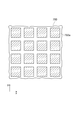
図6及び図10に示すように、封口用マスク設計プログラムは、情報処理装置30に、ワーク画像700中の貫通孔700aの内で、白抜きされて塗りつぶしとなっていないセルである貫通孔700aの中心座標を検出させ、当該中心座標に十字線Ccを表示させる(S209)。
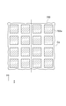
封口用マスク設計プログラムは、情報処理装置30に、ワーク画像700中の中心座標を検出した貫通孔700aについて、貫通孔700aの中心座標とセル1700aの中心とを合わせつつ所定サイズのセル1700aを貼り付けさせる(S210)。封口用マスク設計プログラムは、情報処理装置30に、セル1700aとワーク画像700の貫通孔700aとのサイズの適合状態を判断させ、セル1700aのサイズを調整させる(S211)。
図10に示すように、本実施形態の封口用マスク設計プログラムにおいては、設計するマスク170について規格化された複数のサイズのセル1700aが用意されている。本実施形態においては、設計するマスク170のマスク孔170aを介して封口材Pを封口するハニカム構造体70のセル70aに注入するため、ワーク画像700の貫通孔700aのサイズよりも、設計するマスク170のマスク孔170aのサイズが小さい必要がある。
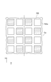
現実に製造されるハニカム構造体70のセル70aの大きさにはバラツキがあるため、封口用マスク設計プログラムは、情報処理装置30に、セル1700aとワーク画像700の貫通孔700aとのサイズの適合状態を貫通孔700aそれぞれについて判断させる。図11(a)に示すように、ワーク画像700の貫通孔700aよりも設計するマスク170のセル1700aが大きい場合は不適である。一方、図11(b)に示すように、ワーク画像700の貫通孔700aよりも設計するマスク170のセル1700aが小さい場合は適合していると判定される。図6及び図12に示すように、封口用マスク設計プログラムは、情報処理装置30に、上記処理をワーク画像700の貫通孔700aそれぞれ全てについて実行させる。
なお、封口用マスク設計プログラムは、情報処理装置30に、規格化された複数のサイズのセル1700aの内で、ワーク画像700中の貫通孔700aそれぞれ全てよりも小さい共通のサイズのセル1700aを設計するマスク170のマスク孔170aと設定させることができる。この場合、実際のマスク170の製造が容易となる。また、封口用マスク設計プログラムは、情報処理装置30に、規格化された複数のサイズのセル1700aの内で、貫通孔700aそれぞれよりもサイズが小さくなるセル1700aの内で最大のサイズのセル1700aをワーク画像700中の貫通孔700aごとに設定させることができる。この場合、実際のハニカム構造体70のセル70aとマスク170のマスク孔170aとの適合状態が良好となる。
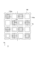
以上のS205~S211の処理により、図13に示すような所定の封口パターンによりセル1700aが設けられた封口用マスク設計画像1700が得られ、設計の本処理が完成する。封口用マスク設計プログラムは、情報処理装置30に、後処理として、設計された封口用マスク設計画像1700、封口するセル70a及びワークであるハニカム構造体70に関する情報及びそれらのCSV(Comma Separated Values)ファイルを出力させる(S212)。
本実施形態によれば、ハニカム構造体70の端部に開口した複数の貫通孔であるセル70aを封口するために、セル70aに対応した貫通孔であるマスク孔170aが形成された封口用マスク170を設計するための封口用マスク設計プログラムは、設計する封口用マスク170が封口するハニカム構造体70の端部の画像に基づいて、封口するセル70aそれぞれの位置を検出する工程と、検出されたセル70aそれぞれの位置に基づいて、設計する封口用マスク170のマスク孔170aの位置を決定する工程とを情報処理装置30に実行させる。このため、設計する封口用マスク170が封口するハニカム構造体70の実際の画像に基づいて、マスク孔170aの位置が決定されることになり、ハニカム構造体70のセル70aそれぞれとの位置合わせを容易に行うことができ、所定のセル70aを確実に封口するのに有用なマスク170を設計することができる。
また、本実施形態によれば、封口用マスク設計プログラムは、設計する封口用マスク170が封口するハニカム構造体70の端部の画像に基づいて、設計する封口用マスク170のマスク孔170aの大きさを決定する工程をさらに情報処理装置30に実行させる。このため、設計する封口用マスク170が封口するハニカム構造体70の実際の画像に基づいて、マスク孔170aの大きさが決定されることになり、所定のセル70aを確実に封口するのに有用なマスク170を設計することができる。
また、本実施形態によれば、設計する封口用マスク170が封口するハニカム構造体70の端部の画像に基づいて、封口するセル70aそれぞれの大きさを検出し、封口するセル70aそれぞれの大きさよりも設計する封口用マスク170のマスク孔170aそれぞれの大きさが小さくなるようにマスク孔170aの大きさを決定する工程を情報処理装置30に実行させる。このため、設計する封口用マスク170のマスク孔170aは、封口する実際のハニカム構造体70のセル70aの大きさに対して封口することに適した大きさに正確に設計することが可能となる。
また、本実施形態によれば、設計する封口用マスク170が封口するハニカム構造体70の端部の画像に基づいて、封口するセル70aそれぞれの中心位置を検出する工程を情報処理装置30に実行させ、検出されたセル70aそれぞれの中心位置と、設計する封口用マスク170のマスク孔170aそれぞれの中心位置とが一致するように、設計する封口用マスク170のマスク孔170aの位置を決定する工程を情報処理装置30に実行させる。セル70aの中心位置とマスク孔170aの中心位置とが一致していることにより、セル70a同士の間隔やセル70aそれぞれの大きさが不均一であったとしても、マスク孔170aの大きさを適切に設計することにより、セル70aを確実に封口することができるマスク170を設計することができる。
尚、本発明は、上記した実施の形態に限定されるものではなく、本発明の要旨を逸脱しない範囲内において種々変更を加え得ることは勿論である。
上記の本発明の一実施形態の封口用マスク設計プログラム及び封口用マスク設計方法によれば、所定のセルを確実に封口するのに有用なマスクを設計することができる。
30 情報処理装置
31 中央処理装置
32 ハードディスク装置
33 主メモリ
34 入力装置
35 表示装置
36 読取装置
37 記録媒体
70 ハニカム構造体
70a 貫通孔
170 封口用マスク
170a 貫通孔
170b マーク
200 封口装置
210 本体部
210d 凹部
210e 連通路
210p 多孔質部材
220 弾性板
225 リング部材
225a 開口
250 ポンプ
251 シリンダ
253 ピストン
255 モータ
700 ワーク画像
700a 貫通孔
1700 封口用マスク設計画像
1700a セル
31 中央処理装置
32 ハードディスク装置
33 主メモリ
34 入力装置
35 表示装置
36 読取装置
37 記録媒体
70 ハニカム構造体
70a 貫通孔
170 封口用マスク
170a 貫通孔
170b マーク
200 封口装置
210 本体部
210d 凹部
210e 連通路
210p 多孔質部材
220 弾性板
225 リング部材
225a 開口
250 ポンプ
251 シリンダ
253 ピストン
255 モータ
700 ワーク画像
700a 貫通孔
1700 封口用マスク設計画像
1700a セル
Claims (8)
- ハニカム構造体の端部に開口した複数の貫通孔であるセルを封口するために、前記セルに対応した貫通孔であるマスク孔が形成された封口用マスクを設計するための封口用マスク設計プログラムであって、
設計する前記封口用マスクが封口する前記ハニカム構造体の前記端部の画像に基づいて、封口する前記セルそれぞれの位置を検出するセル位置検出工程と、
前記セル位置検出工程で検出された前記セルそれぞれの位置に基づいて、設計する前記封口用マスクの前記マスク孔の位置を決定するマスク孔位置決定工程と、
を情報処理装置に実行させる封口用マスク設計プログラム。 - 設計する前記封口用マスクが封口する前記ハニカム構造体の前記端部の画像に基づいて、設計する前記封口用マスクの前記マスク孔の大きさを決定するマスク孔サイズ決定工程をさらに前記情報処理装置に実行させる、請求項1に記載の封口用マスク設計プログラム。
- 前記マスク孔サイズ決定工程では、設計する前記封口用マスクが封口する前記ハニカム構造体の前記端部の画像に基づいて、封口する前記セルそれぞれの大きさを検出し、封口する前記セルそれぞれの大きさよりも設計する前記封口用マスクの前記マスク孔それぞれの大きさが小さくなるように前記マスク孔の大きさを決定する前記マスク孔サイズ決定工程を前記情報処理装置に実行させる、請求項2に記載の封口用マスク設計プログラム。
- 前記セル位置検出工程では、設計する前記封口用マスクが封口する前記ハニカム構造体の前記端部の画像に基づいて、封口する前記セルそれぞれの中心位置を検出する前記セル位置検出工程を前記情報処理装置に実行させ、
前記マスク孔位置決定工程では、前記セル位置検出工程で検出された前記セルそれぞれの中心位置と、設計する前記封口用マスクの前記マスク孔それぞれの中心位置とが一致するように、設計する前記封口用マスクの前記マスク孔の位置を決定する前記マスク孔位置決定工程を前記情報処理装置に実行させる、請求項1~3のいずれか1項に記載の封口用マスク設計プログラム。 - ハニカム構造体の端部に開口した複数の貫通孔であるセルを封口するために、前記セルに対応した貫通孔であるマスク孔が形成された封口用マスクを設計する封口用マスク設計方法であって、
設計する前記封口用マスクが封口する前記ハニカム構造体の前記端部の画像に基づいて、封口する前記セルそれぞれの位置を検出するセル位置検出工程と、
前記セル位置検出工程で検出された前記セルそれぞれの位置に基づいて、設計する前記封口用マスクの前記マスク孔の位置を決定するマスク孔位置決定工程と、
を含む封口用マスク設計方法。 - 設計する前記封口用マスクが封口する前記ハニカム構造体の前記端部の画像に基づいて、設計する前記封口用マスクの前記マスク孔の大きさを決定するマスク孔サイズ決定工程をさらに含む、請求項5に記載の封口用マスク設計方法。
- 前記マスク孔サイズ決定工程では、設計する前記封口用マスクが封口する前記ハニカム構造体の前記端部の画像に基づいて、封口する前記セルそれぞれの大きさを検出し、封口する前記セルそれぞれの大きさよりも設計する前記封口用マスクの前記マスク孔それぞれの大きさが小さくなるように前記マスク孔の大きさを決定する、請求項6に記載の封口用マスク設計方法。
- 前記セル位置検出工程では、設計する前記封口用マスクが封口する前記ハニカム構造体の前記端部の画像に基づいて、封口する前記セルそれぞれの中心位置を検出し、
前記マスク孔位置決定工程では、前記セル位置検出工程で検出された前記セルそれぞれの中心位置と、設計する前記封口用マスクの前記マスク孔それぞれの中心位置とが一致するように、設計する前記封口用マスクの前記マスク孔の位置を決定する、請求項5~7のいずれか1項に記載の封口用マスク設計方法。
Applications Claiming Priority (2)
| Application Number | Priority Date | Filing Date | Title |
|---|---|---|---|
| JP2011021876A JP2012161934A (ja) | 2011-02-03 | 2011-02-03 | 封口用マスク設計プログラム及び封口用マスク設計方法 |
| JP2011-021876 | 2011-02-03 |
Publications (1)
| Publication Number | Publication Date |
|---|---|
| WO2012105419A1 true WO2012105419A1 (ja) | 2012-08-09 |
Family
ID=46602636
Family Applications (1)
| Application Number | Title | Priority Date | Filing Date |
|---|---|---|---|
| PCT/JP2012/051719 Ceased WO2012105419A1 (ja) | 2011-02-03 | 2012-01-26 | 封口用マスク設計プログラム及び封口用マスク設計方法 |
Country Status (2)
| Country | Link |
|---|---|
| JP (1) | JP2012161934A (ja) |
| WO (1) | WO2012105419A1 (ja) |
Citations (4)
| Publication number | Priority date | Publication date | Assignee | Title |
|---|---|---|---|---|
| JP2002028915A (ja) * | 2000-05-12 | 2002-01-29 | Denso Corp | セラミックハニカム構造体の製造方法及び貫通穴形成装置 |
| JP2005059512A (ja) * | 2003-08-19 | 2005-03-10 | Ngk Insulators Ltd | 目封止ハニカム構造体の製造方法、これに用いる目封止部形成用マスク、及びその製造方法 |
| JP2007283755A (ja) * | 2006-03-23 | 2007-11-01 | Ngk Insulators Ltd | 目封止ハニカム構造体の製造方法及び目封止ハニカム構造体 |
| JP2009516586A (ja) * | 2005-11-22 | 2009-04-23 | コーニング インコーポレイテッド | ハニカム基体用の施栓マスクを製造するための装置、システムおよび方法 |
-
2011
- 2011-02-03 JP JP2011021876A patent/JP2012161934A/ja not_active Withdrawn
-
2012
- 2012-01-26 WO PCT/JP2012/051719 patent/WO2012105419A1/ja not_active Ceased
Patent Citations (4)
| Publication number | Priority date | Publication date | Assignee | Title |
|---|---|---|---|---|
| JP2002028915A (ja) * | 2000-05-12 | 2002-01-29 | Denso Corp | セラミックハニカム構造体の製造方法及び貫通穴形成装置 |
| JP2005059512A (ja) * | 2003-08-19 | 2005-03-10 | Ngk Insulators Ltd | 目封止ハニカム構造体の製造方法、これに用いる目封止部形成用マスク、及びその製造方法 |
| JP2009516586A (ja) * | 2005-11-22 | 2009-04-23 | コーニング インコーポレイテッド | ハニカム基体用の施栓マスクを製造するための装置、システムおよび方法 |
| JP2007283755A (ja) * | 2006-03-23 | 2007-11-01 | Ngk Insulators Ltd | 目封止ハニカム構造体の製造方法及び目封止ハニカム構造体 |
Also Published As
| Publication number | Publication date |
|---|---|
| JP2012161934A (ja) | 2012-08-30 |
Similar Documents
| Publication | Publication Date | Title |
|---|---|---|
| US9822681B2 (en) | Plugged honeycomb structure and manufacturing method of the same | |
| US10540775B2 (en) | Porous body, honeycomb filter, microstructure analysis method, program for same, and microstructure analyzer | |
| WO2009119251A1 (ja) | 目封止ハニカム構造体の製造装置、及びその製造方法 | |
| WO2017073628A1 (ja) | ハニカム構造体の端面検査方法、及び端面検査装置 | |
| WO2013008789A1 (ja) | ハニカム構造体の検査方法、ハニカム構造体の製造方法及びハニカム構造体の検査装置 | |
| CN110018117A (zh) | 密合强度测定方法 | |
| CN111699383A (zh) | 气体传感器 | |
| EP3403203A1 (en) | Non-contact method of characterizing isostatic strength of cellular ceramic articles | |
| WO2012105419A1 (ja) | 封口用マスク設計プログラム及び封口用マスク設計方法 | |
| JP2013142669A (ja) | グリーンハニカム成形体の欠陥を検査する方法、グリーンハニカム構造体の製造方法及びグリーンハニカム成形体の欠陥の検査装置 | |
| EP3298583B1 (en) | Methods for inspecting cellular articles | |
| WO2013008790A1 (ja) | ハニカム構造体の検査方法、ハニカム構造体の製造方法及びハニカム構造体の検査装置 | |
| JP6254474B2 (ja) | 多孔質体,ハニカムフィルタ及び多孔質体の製造方法 | |
| CN102829750B (zh) | 一种检测缸盖外形尺寸的测量方法及装置 | |
| EP3149458B1 (en) | System and method for inspecting a body | |
| JPWO2009069378A1 (ja) | 目封止ハニカム構造体の接合方法 | |
| JP5091252B2 (ja) | ハニカム構造体端面のマスク不良検出方法 | |
| Zhou et al. | RoboCam: Model-based robotic visual sensing for precise inspection of mesh screens | |
| CN108168475B (zh) | 运输机火焰筒异型气膜孔异型角度的测量方法 | |
| JP2002167033A (ja) | パーツガイドロータ | |
| CN205192402U (zh) | 测量用钩针 | |
| JP7733199B2 (ja) | 所定の設計仕様の焼成後の柱状ハニカム成形体が得られるか否かを予測する方法 | |
| CN110173998A (zh) | 构建或拆解收纳架的方法、陶瓷烧成体的制造方法、以及搬送系统 | |
| JP4938904B2 (ja) | ハニカム構造体の封口方法 | |
| CN116109620A (zh) | 电池密封钉的图像检测方法、装置及设备 |
Legal Events
| Date | Code | Title | Description |
|---|---|---|---|
| 121 | Ep: the epo has been informed by wipo that ep was designated in this application |
Ref document number: 12741661 Country of ref document: EP Kind code of ref document: A1 |
|
| NENP | Non-entry into the national phase |
Ref country code: DE |
|
| 122 | Ep: pct application non-entry in european phase |
Ref document number: 12741661 Country of ref document: EP Kind code of ref document: A1 |