WO2012105336A1 - 基板搬送用キャリア - Google Patents
基板搬送用キャリア Download PDFInfo
- Publication number
- WO2012105336A1 WO2012105336A1 PCT/JP2012/051201 JP2012051201W WO2012105336A1 WO 2012105336 A1 WO2012105336 A1 WO 2012105336A1 JP 2012051201 W JP2012051201 W JP 2012051201W WO 2012105336 A1 WO2012105336 A1 WO 2012105336A1
- Authority
- WO
- WIPO (PCT)
- Prior art keywords
- adhesive layer
- resin film
- substrate
- support
- carrier
- Prior art date
- Legal status (The legal status is an assumption and is not a legal conclusion. Google has not performed a legal analysis and makes no representation as to the accuracy of the status listed.)
- Ceased
Links
Images




Classifications
-
- H—ELECTRICITY
- H10—SEMICONDUCTOR DEVICES; ELECTRIC SOLID-STATE DEVICES NOT OTHERWISE PROVIDED FOR
- H10P—GENERIC PROCESSES OR APPARATUS FOR THE MANUFACTURE OR TREATMENT OF DEVICES COVERED BY CLASS H10
- H10P72/00—Handling or holding of wafers, substrates or devices during manufacture or treatment thereof
- H10P72/70—Handling or holding of wafers, substrates or devices during manufacture or treatment thereof for supporting or gripping
- H10P72/74—Handling or holding of wafers, substrates or devices during manufacture or treatment thereof for supporting or gripping using temporarily an auxiliary support
- H10P72/7402—Wafer tapes, e.g. grinding or dicing support tapes
-
- H—ELECTRICITY
- H10—SEMICONDUCTOR DEVICES; ELECTRIC SOLID-STATE DEVICES NOT OTHERWISE PROVIDED FOR
- H10P—GENERIC PROCESSES OR APPARATUS FOR THE MANUFACTURE OR TREATMENT OF DEVICES COVERED BY CLASS H10
- H10P72/00—Handling or holding of wafers, substrates or devices during manufacture or treatment thereof
- H10P72/70—Handling or holding of wafers, substrates or devices during manufacture or treatment thereof for supporting or gripping
- H10P72/74—Handling or holding of wafers, substrates or devices during manufacture or treatment thereof for supporting or gripping using temporarily an auxiliary support
- H10P72/744—Details of chemical or physical process used for separating the auxiliary support from a device or a wafer
- H10P72/7442—Separation by peeling
-
- Y—GENERAL TAGGING OF NEW TECHNOLOGICAL DEVELOPMENTS; GENERAL TAGGING OF CROSS-SECTIONAL TECHNOLOGIES SPANNING OVER SEVERAL SECTIONS OF THE IPC; TECHNICAL SUBJECTS COVERED BY FORMER USPC CROSS-REFERENCE ART COLLECTIONS [XRACs] AND DIGESTS
- Y02—TECHNOLOGIES OR APPLICATIONS FOR MITIGATION OR ADAPTATION AGAINST CLIMATE CHANGE
- Y02W—CLIMATE CHANGE MITIGATION TECHNOLOGIES RELATED TO WASTEWATER TREATMENT OR WASTE MANAGEMENT
- Y02W30/00—Technologies for solid waste management
- Y02W30/50—Reuse, recycling or recovery technologies
- Y02W30/80—Packaging reuse or recycling, e.g. of multilayer packaging
Definitions
- the present invention relates to a substrate carrying carrier for carrying a substrate such as a printed wiring board on which a semiconductor device and a small component are mounted.
- FPC flexible printed wiring board
- Patent Document 1 a method of using a jig called a carrier for transporting a substrate is disclosed when electronic component mounting, chemical cleaning, plasma processing, or the like is performed on the FPC (Patent Document 1). More specifically, in Patent Document 1, a carrier having flexibility and carrying a flexible wiring board is carried to a mounting position of an electronic component, and the carrier is installed on the surface carrying the flexible wiring board. A flexible wiring board transport jig comprising the adhesive layer thus formed is disclosed.
- the flexible wiring board transport jig is mounted on a transport plate and is transported together with the transport plate to each step such as a solder printing process, an electronic component mounting process, and a reflow process in the mounting process.
- maintains four corners of the conveyance jig for flexible wiring boards with a heat resistant adhesive tape when the conveyance jig for flexible wiring boards is attached to a conveyance board is disclosed.
- the adhesive tape is adhered after a process involving heating such as a reflow process. Since the force is increased, the adhesive tape is difficult to peel off, and the workability is lowered. As a result, the production efficiency of the wiring board that is the object to be conveyed is lowered. Moreover, when the adhesive force of an adhesive tape increases, when peeling an adhesive tape, stress will be applied to a conveyance jig and the flatness may be lost. Usually, the transport jig is used repeatedly.
- the adhesive tape residue (cured product of the adhesive) may remain on the conveying jig after the adhesive tape is peeled off. Such a residue causes contamination in an electronic component mounting process or the like.
- the adhesive tape is placed on the residue when the transport substrate is used repeatedly, the adhesive force of the adhesive tape is weakened, and the position of the transport jig on the transport plate is liable to occur. May cause misalignment.
- the present invention prevents the occurrence of positional deviation of the conveyed object even when a heat treatment such as a reflow process is performed, and destroys or deforms the conveyed object at the time of peeling the conveyed object.
- An object of the present invention is to provide a carrier for transporting a substrate that can be used repeatedly.
- the present inventors have repeatedly performed a resin film with an adhesive layer having an adhesive layer that is detachably attached to an object to be transported, and a rigid (rigid) support. It discovered that the said subject could be solved by using and fixing it with the fixing means which can be used. That is, the present inventors have found that the above object can be achieved by the following means.
- a carrier for transporting a substrate used for transporting a substrate On the resin film having a linear expansion coefficient of 50 ppm / ° C. or less, an adhesive layer-attached resin film provided with an adhesive layer that comes into close contact with the lower surface of the substrate; A support composed of a metal or metal oxide; A reusable fixing means for removably fixing the resin film with an adhesive layer on the support, with the surface opposite to the surface having the adhesive layer of the resin film with the adhesive layer and the surface of the support being laminated.
- a carrier for transporting a substrate On the resin film having a linear expansion coefficient of 50 ppm / ° C. or less, an adhesive layer-attached resin film provided with an adhesive layer that comes into close contact with the lower surface of the substrate; A support composed of a metal or metal oxide; A reusable fixing means for removably fixing the resin film with an adhesive layer on the support, with the surface opposite to the surface having the adhesive layer of the resin film with the adhesive layer and the surface of the support being laminated.
- the support has a screw hole on its surface, A pressing member having a L-shaped cross section comprising a vertical plate portion extending substantially perpendicular to the support surface and a horizontal plate portion extending in a substantially orthogonal direction from the upper end of the vertical plate portion and having a through hole.
- the present invention even when a heat treatment such as a reflow process is performed, the occurrence of positional deviation of the conveyed object is suppressed, and the occurrence of the destruction or deformation of the conveyed object is suppressed when the conveyed object is peeled off.
- a carrier for transporting a substrate that can be used repeatedly.
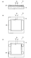
- FIGS. 1A and 1B are a cross-sectional view and a top view, respectively, showing a first embodiment of a carrier for transporting a substrate according to the present invention.
- FIG. 1C is a top view showing another aspect of the first embodiment.
- FIGS. 2A and 2B are a cross-sectional view and a top view showing another aspect of the first embodiment of the substrate carrying carrier of the present invention.
- 3A and 3B are a cross-sectional view and a top view showing another aspect of the first embodiment of the carrier for transporting a substrate of the present invention.
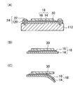
- FIG. 4 is a schematic cross-sectional view of the carrier for transporting a substrate, showing a procedure until the object to be transported is peeled off.
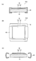
- FIGS. 5A and 5B are a cross-sectional view and a top view showing a second embodiment of the substrate carrying carrier of the present invention.
- FIG. 5C is a cross-sectional view of the carrier for transporting a substrate when the gripping member is removed.
- FIGS. 6A and 6B are a side view and a top view showing another aspect of the second embodiment of the carrier for transporting a substrate of the present invention.
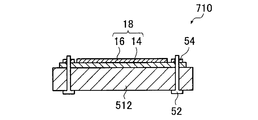
- FIG. 7 is a cross-sectional view showing a third embodiment of the carrier for transporting a substrate of the present invention.
- FIG. 8: is sectional drawing which shows another aspect of 3rd Embodiment of the carrier for board
- FIG. 9 is sectional drawing which shows another aspect of 3rd Embodiment of the carrier for board
- substrate conveyance of this invention is explained in full detail.
- the feature of the present invention compared with the prior art is that a resin film with an adhesive layer having an adhesive layer that can be peeled and adhered to a transported object, and a rigid support made of a metal or a metal oxide.
- the point which fixes and uses the body using the fixing means which can be used repeatedly is mentioned.
- the adhesive layer-attached resin film is fixed on a rigid support via a fixing means, and deformation such as warpage or twisting of the adhesive layer-attached resin film is suppressed. .
- the fixing means when peeling the object to be transported from the adhesive layer, first, the fixing means is released, the resin film with the adhesive layer is removed from the support, and then the resin film with the adhesive layer is peeled off while being folded.
- a to-be-conveyed object can be peeled, suppressing that destruction and deformation
- the adhesive part will harden
- the heat resistant adhesive tape of patent document 1 cannot be repeatedly used, it is not contained in the fixing means of this invention. If the fixing means (for example, a screw member, a gripping member, etc.) of the present invention is used, problems that occur when using a heat-resistant adhesive tape can be solved.
- First Embodiment> 1A and 1B are a cross-sectional view and a top view, respectively, showing a first embodiment of a carrier for transporting a substrate according to the present invention.
- 1 includes a support 12, a resin film 18 with an adhesive layer in which an adhesive layer 16 is provided on one surface of a resin film 14, and a pressing member 20 as a fixing means.
- a support 12 a resin film 18 with an adhesive layer in which an adhesive layer 16 is provided on one surface of a resin film 14
- a pressing member 20 as a fixing means.
- the support 12 is a support made of metal or metal oxide.
- the support supports a resin film 18 with an adhesive layer, which will be described later, and suppresses warping or twisting of the film 18.
- the support 12 only needs to be made of a metal or a metal oxide, and specifically includes a metal support, a metal oxide support, or a laminate of these substrates.
- the kind in particular of metal support body is not restrict
- the type of the metal oxide support is not particularly limited, and examples thereof include a glass substrate, a quartz substrate, and an alumina substrate.
- the support 12 composed of the components as described above generally has higher rigidity than the resin film 18 with an adhesive layer described later, and is less likely to bend or deform. More specifically, the Young's modulus of the support 12 is preferably about 20 to 1000 GPa, more preferably about 30 to 500 GPa. The Young's modulus is a value measured according to JIS R 1602.
- the length and width of the support 12 can be adjusted as appropriate according to the size of the conveyed object.
- the thickness of the support 12 is not particularly limited, but is preferably about 0.5 to 100 mm from the viewpoint of handling properties and suppressing warpage or twisting of the resin film 18 with an adhesive layer.
- the resin film 18 with an adhesive layer includes a resin film 14 and an adhesive layer 16 provided on the surface of the resin film 14.
- the resin film 18 with an adhesive layer is disposed on the support 12 such that the surface opposite to the surface on which the adhesive layer 16 is located faces the support 12.
- the surface opposite to the surface on which the pressure-sensitive adhesive layer 16 is provided is a laminated surface that is laminated on the surface of the support 12.
- the pressure-sensitive adhesive layer 16 is a layer (resin layer) that can be in close contact with a substrate (not shown) that is disposed on the surface thereof, can hold the position of the close-contacted substrate, Twist can be prevented.
- the adhesive force between the adhesive layer 16 and the resin film 14 is higher than the adhesive force between the adhesive layer 16 and a substrate (for example, a rigid substrate) disposed on the surface thereof.
- a substrate for example, a rigid substrate
- the resin film 14 is a film made of a resin that exhibits a predetermined linear expansion coefficient.
- the resin film 14 is a flexible film that can be bent and the like, and the deformation / destruction of the substrate can be suppressed by peeling the film from the substrate while bending the film.
- the linear expansion coefficient of the resin film 14 is 50 ppm / ° C. or less.
- a linear expansion coefficient is 45 ppm / degrees C or less, and it is more preferable that it is 30 ppm / degrees C or less from the point which the effect of this invention is more excellent.
- the lower limit is not particularly limited, but is usually 1 ppm / ° C. or higher.
- the linear expansion coefficient can be measured by a known measuring means (for example, TMA (Thermo-Mechanical Analyzer)).
- the glass transition temperature (Tg) of the resin film 14 is not particularly limited, but is preferably 150 to 500 ° C. and more preferably 200 to 500 ° C. from the viewpoint of suppressing twisting and warping in a high temperature environment.
- the glass transition temperature can be measured by a known measuring means (for example, DMA (Dynamic Mechanical Analysis)).
- the resin film 14 is preferably flexible to such an extent that it can be bent when the substrate, which is a transported object, is peeled off. More specifically, the Young's modulus of the resin film 14 is preferably about 0.01 to 15 GPa, and more preferably about 0.1 to 10 GPa. The Young's modulus is a value measured according to JIS K 7161. The Young's modulus of the resin film 14 is preferably smaller than the Young's modulus of the support 12.
- the type of resin constituting the resin film 14 is not particularly limited as long as it satisfies the linear expansion coefficient, and examples thereof include polyimide, polyamide, polyetherketone, and polyetheretherketone.
- polyimide and polyamide for example, aramid are mentioned because they are excellent in heat resistance and more excellent in adhesion to the adhesive layer 16.
- the length and width of the resin film 14 can be appropriately adjusted according to the size of the conveyed object.
- the thickness of the resin film 14 is not particularly limited, but is preferably 1 to 1000 ⁇ m and more preferably 5 to 200 ⁇ m from the viewpoint of handleability when the substrate is peeled off.
- the adhesive layer 16 is not particularly limited as long as its surface can be peeled and adhered to the lower surface of the substrate (resin layer).
- the resin contained in the adhesive layer 16 include a urethane resin and a polyvinyl alcohol resin. Or a silicone resin. Among these, a silicone resin is preferable from the viewpoint of chemical resistance and peelability. That is, the adhesive layer is preferably a silicone resin layer.
- a silicone resin layer intends the layer in which a silicone resin is contained as a main component.
- the thickness of the pressure-sensitive adhesive layer 16 is appropriately set according to the type of substrate disposed thereon, but is preferably 0.1 to 1000 ⁇ m and more preferably 10 to 500 ⁇ m from the viewpoint of chemical resistance and peelability.
- the procedure for forming the adhesive layer 16 on the resin film 14 is not particularly limited, and a method for fixing the film-like adhesive layer 16 on the resin film 14 or a composition containing the component constituting the adhesive layer 16 or a precursor thereof.
- coating to the resin film 14 and forming the adhesion layer 16 etc. are mentioned.
- coating a composition on the resin film 14 at the point which the adhesiveness of the resin film 14 and the adhesion layer 16 is more excellent is preferable.
- coating of a composition heat processing is performed as needed for the removal of a solvent, hardening of a precursor, etc.
- the conditions for the heat treatment are appropriately set according to the material to be used, but from the viewpoint of stabilizing the adhesive layer, it is preferable to carry out at 50 to 300 ° C. for 0.5 to 12 hours.
- a preferable embodiment of the adhesive layer 16 is a silicone resin layer obtained by using a composition obtained by subjecting a mixture having a silicate compound and an organopolysiloxane having a terminal silicate-modified to a hydrolysis reaction and a condensation reaction. It is done. If it is this silicone resin layer, while being excellent in heat resistance and chemical resistance, the peelability of the board
- the organopolysiloxane it is preferable to use polydimethylsiloxane because the effects of the present invention are more excellent.
- the organopolysiloxane is polydimethylsiloxane will be described in detail.
- Polydimethylsiloxane is abbreviated as “PDMS”
- polydimethylsiloxane whose terminal is silicate-modified is abbreviated as “modified PDMS”.
- the silicate compound of the present invention is a metal alkoxide (alkoxysilane compound (particularly, tetraalkoxysilane compound)) made of silicon (Si) or an oligomer thereof.
- An oligomer is a compound having a siloxane (—Si—O—Si—) skeleton in the main chain and an alkoxy group (RO) introduced in the side chain.
- (R) which is the alkyl part of the alkoxy group (RO) is exemplified by a methyl group, an ethyl group, a propyl group, and the like.
- This silicate compound has the property of easily reacting with water.
- the silicate compound is desirably a tetramer to a 16-mer (a tetramer or more and a 16-mer or less). If the amount is less than the tetramer, the effect of the characteristics of the silicate compound is small. If the amount exceeds the 16-mer, the viscosity of the silicate compound is increased, which makes it difficult to handle at the time of production.
- examples of the silicate compound used in the present invention include methyl silicate, ethyl silicate, propyl silicate and the like, or oligomers thereof. From the viewpoints of quality stability and safety, ethyl silicate or an oligomer thereof is preferred.
- the adhesiveness to the support body of an adhesion layer improves more.
- the pressure-sensitive adhesive layer is a silicone resin layer (more preferably, the pressure-sensitive adhesive layer is a resin layer formed by reacting terminal silicate-modified silicone), the effect of the present invention is more excellent.
- a preferred embodiment of the silicate compound represented by the chemical formula 1 includes a compound represented by the following formula (X).
- R 1 is an alkyl group having 4 or less carbon atoms
- n is an integer of 4 to 16.
- the silicate compound may be synthesized according to a known method, or a commercially available product (for example, ethyl silicate 45 (manufactured by Tama Chemical Industries)) may be used.
- Modified PDMS is obtained by modifying the end of PDMS with a silicate compound.
- a silicate compound For example, PDMS having silanol groups at both ends and an alkoxy group which is a hydrolyzable functional group on one side or both sides of the main chain. What is obtained by making it react with the alkoxysilane partial condensate which has.
- This modified PDMS has a much higher functional group concentration than ordinary PDMS. Further, since the modified PDMS has high condensation reactivity with the silicate compound, the alkoxysilane partial condensate contained in the modified PDMS can be smoothly polymerized by being subjected to a condensation reaction smoothly.
- the modified PDMS used in the present invention preferably has a mass average molecular weight in the range of 5000 or more and 100,000 or less.
- Modified PDMS may be synthesized with reference to a known synthesis method (for example, Japanese Patent No. 4255088) or a commercially available product may be used.
- denatured PDMS (B) is the range of 0.1-10, in the molar ratio of A / B.
- the optimum blending ratio is around 1 in terms of A / B molar ratio.
- the silicate compound is preferably increased.
- composition is produced by hydrolyzing and condensing a mixture having the silicate compound and the modified PDMS.
- silicate compound Since the silicate compound is easily hydrolyzed in the presence of water, the alkoxy group in the molecule of the silicate compound becomes a highly reactive silanol group (—OH group).
- the modified PDMS is also hydrolyzed to form a silanol group (also referred to as “silanol modification”) due to the presence of water.
- the composition is liquid (also referred to as “sol”)
- the desired adhesive layer 16 is formed by applying the composition onto the resin film 14 as described above and performing heat treatment as necessary. It can be formed on the resin film 14.
- the application method and heating conditions are as described above.
- the composition is applied to a tray such as a mold, and is cured by a drying and firing treatment to be formed into a sheet (plate), and the adhesive layer 16 formed into the sheet is used as a resin.
- the film 14 is fixed (held) in close contact with or adhered to the surface of the film 14.
- a pressing member that abuts the surface of the resin film with the adhesive layer on which the adhesive layer is present and presses the film toward the support is used.
- this member the position shift of the resin film with an adhesive layer on a support body and the deformation
- the pressing member 20 is fixed on the vicinity of the peripheral edge of the support 12, and is provided with a vertical plate portion extending substantially vertically and a substantially orthogonal direction extending from the upper end of the vertical plate portion. Is a member having an L-shaped cross section composed of a horizontal plate portion that abuts and presses the resin film 18 with an adhesive layer toward the support 12 side. As shown in FIG. 1, the front-end
- the pressing member 20 is an elastically deformable member, and presses the adhesive layer-attached resin film 18 toward the support 12 based on its own elastic force. In FIG.
- two pressing members 20 are provided so as to oppose the vicinity of the peripheral edge of the resin film 18 with the adhesive layer, but the arrangement position and number thereof are not particularly limited.
- four pressing members 20 having a short horizontal plate portion may be disposed.
- the elastic member used as the holding member 20 is preferably an elastic member having elasticity and a certain degree of rigidity.
- a metal material such as stainless steel, an aluminum alloy, a shape memory alloy, or a resin material such as polyamide or polycarbonate is used. Can be mentioned.
- FIGS. 2A and 2B are a cross-sectional view and a top view showing another aspect of the first embodiment of the substrate carrying carrier of the present invention.
- the fixing means 24 includes a vertical plate portion extending substantially perpendicular to the surface of the support 112, a substantially orthogonal direction extending from the upper end of the vertical plate portion, A holding member 120 having a L-shaped cross section composed of a lateral plate portion that abuts and having a through hole in the lateral plate portion, and a bolt 22 that passes through the through hole and is screwed into a screw hole provided in the support body 112. Is done.
- the lateral plate portion of the pressing member 120 abuts on the resin film 18 with the adhesive layer (particularly, the resin film 14), and the pressing member 120 causes The resin film 18 with an adhesive layer can be fixed to the surface. That is, by adjusting the degree to which the bolt 22 is tightened (screwed), the degree to which the pressing member 120 presses the resin film 18 with the adhesive layer can be adjusted. Moreover, if it is this aspect, the resin film 18 with an adhesion layer can be fixed on the support body 112, without providing the penetration hole which the volt
- the material used as the pressing member 120 is not particularly limited, and a metal material, a resin material, or the like is used. In this aspect, the bolt 22 corresponds to the screw member.
- the pressing member 120 is not fixed on the support body 112 but is detachably disposed on the support body 112.
- the pressing member 120 is not limited to the embodiment shown in FIGS. 2A and 2B, and the vertical plate portion may be fixed to the peripheral portion of the support 112. 2A and 2B, two pressing members 120 are used so as to face each other, but the number of pressing members 120 used is not limited to this mode.
- the number of bolts 22 used is four, but the position and number of the bolts 22 used are not limited to this embodiment.
- the number of bolts 22 that pass through one presser member 120 is two, but the number of bolts 22 that pass through one presser member 120 is limited to this mode.
- the fixing means includes a vertical plate portion extending substantially perpendicular to the surface of the support 212 and a substantially orthogonal direction extending from the upper end of the vertical plate portion, and contacts the resin film 18 with an adhesive layer.
- a holding member 120 having an L-shaped cross section composed of a lateral plate portion that is in contact and having a through hole in the lateral plate portion, one end is embedded and fixed in the support body 212, and the other end is discharged onto the surface of the support body 12, It is comprised from the implantation bolt 26 which penetrates a hole, and the nut 28 screwed together.
- the presser member 120 is disposed on the support body 212 so that the through hole of the horizontal plate portion of the presser member 120 is inserted through the stud bolt 26, and the nut 28 is screwed into the stud bolt 26 to press the presser foot.
- the horizontal plate portion of the member 120 abuts on the resin film 18 with the adhesive layer, and the resin film 18 with the adhesive layer can be fixed on the support 212 by the pressing member 120. That is, if it is this aspect, the degree to which the pressing member 120 presses the resin film 18 with the adhesion layer can be adjusted by adjusting the degree of screwing of the nut 28. Moreover, if it is this aspect, the resin film 18 with an adhesion layer can be fixed on the support body 212, without providing the penetration hole which the implantation bolt 26 penetrates in the resin film 18 with an adhesion layer. In this mode, the stud bolt 26 corresponds to the screw member.
- two pressing members 120 are used so as to face each other, but the number of pressing members 120 used is not limited to this mode.
- the number of studs 26 used is four, but the position and number of studs 26 used are not limited to this mode.
- the number of the stud bolts 26 that pass through one presser member 120 is two, but the number of the stud bolts 26 that pass through one presser member 120 corresponds to this mode. Is not limited.
- description is abbreviate
- the above-described carrier for transporting a substrate is a carrier that can transport a substrate to a reflow furnace or the like by bonding a transported object such as a printed wiring board to the surface of the adhesive layer.
- a transported object such as a printed wiring board
- FIG. 4 an aspect in which the object to be conveyed is peeled from the substrate conveying carrier will be described in detail. More specifically, an embodiment using the substrate carrying carrier 110 shown in FIG. 4A, first, the substrate 30 that is the object to be transported is bonded to the surface of the adhesive layer 16 and subjected to various treatments.
- the board 30 is not limited to a printed wiring board such as a rigid board, and is not particularly limited as long as it is a rigid base material.
- the fixing means 24 is released, and the resin film 18 with the adhesive layer is removed from the support 112 (FIG. 4B). More specifically, the bolt 22 is removed from the screw hole of the support 112. Thereafter, when the substrate 30 is peeled from the adhesive layer 16, the tip of the resin film 18 with the adhesive layer is moved away from the substrate 30 while bending the resin film 18 with the adhesive layer, and the substrate 30 and the resin with the adhesive layer are moved. The film 18 is separated (FIG. 4C). By following the above procedure, the substrate 30 can be peeled from the adhesive layer 16 without causing deformation or destruction of the substrate 30 after completion of predetermined processing such as mounting of electronic components.
- FIGS. 5A and 5B are a cross-sectional view and a top view showing a second embodiment of the substrate carrying carrier of the present invention.
- a carrier 310 for transporting a substrate in FIG. 5 includes a gripping member 40 that sandwiches the end portions of the resin film 18 with an adhesive layer and the support 12 and fixes the resin film 18 with an adhesive layer on the support 12 as fixing means.
- the gripping member 40 is a member having a substantially U-shaped cross section including a vertical plate portion and a pair of horizontal plate portions extending in a substantially orthogonal direction from both ends of the vertical plate portion.
- the horizontal plate portion is a first horizontal plate portion that contacts the surface of the resin film 18 with the adhesive layer on the side where the adhesive layer 16 is present and the surface on the opposite side of the surface of the support 12 where the resin film 18 with the adhesive layer is present. And a second horizontal plate portion in contact with.
- the member may be an elastic member, for example, an elastic member in which the distal end portion of the first lateral plate portion and the distal end portion of the second lateral plate portion tend to approach each other due to the elastic force they have. (For example, a clip).
- an elastic member for example, an elastic member in which the distal end portion of the first lateral plate portion and the distal end portion of the second lateral plate portion tend to approach each other due to the elastic force they have.
- a clip When such an elastic member is used, first, when the gripping member 40 is disposed so as to sandwich the support 12 and the resin film 18 with the adhesive layer, the distal end portion of the first horizontal plate portion and the second portion are arranged. The horizontal plate portion is elastically deformed so as to be separated from the tip portion of the horizontal plate portion by a predetermined distance.
- the gripping member 40 is provided with elasticity that the leading end portion of the first horizontal plate portion and the leading end portion of the second horizontal plate portion return to their original positions.
- the gripping member 40 is pressed so as to sandwich the support 12 and the resin film 18 with the adhesive layer, and the resin film 18 with the adhesive layer is fixed on the support 12 by this pressing force.
- the gripping member 40 is removed, the first lateral plate portion and the second lateral plate of the gripping member 40 are released from the restraint by the support 12 and the resin film 18 with the adhesive layer, and based on the elastic force that the gripping member 40 has.
- the elastic member used preferably has elasticity and a certain degree of rigidity, and examples thereof include metal materials such as stainless steel, aluminum alloy and shape memory alloy, or resin materials such as polyamide and polycarbonate. .
- FIG. 5 (B) two gripping members 40 are disposed so as to oppose the vicinity of the peripheral edge of the resin film 18 with the adhesive layer, but the number and arrangement position thereof are not particularly limited.
- the gripping member is not limited to the embodiment shown in FIG. 5, and the shape thereof is not particularly limited as long as the support and the adhesive layer-attached resin film can be sandwiched and gripped (held).
- FIGS. 6A and 6B are a side view and a top view showing another aspect of the second embodiment of the carrier for transporting a substrate of the present invention.
- the fixing means has a substantially U-shaped cross section composed of a vertical plate portion and a pair of horizontal plate portions extending in the orthogonal direction from both ends of the vertical plate portion.
- the gripping member 140 provided with the insertion hole and the bolt insertion hole are connected to the tip portions of the pair of horizontal plate portions, and the interval between the tip portions is fastened and fixed in a freely adjustable manner.
- Bolts 42 and nuts 44 may be provided.
- the pressing force to the support body 12 of the resin film 18 with the adhesion layer can be adjusted by adjusting the tightening degree of the nut 44.
- description is abbreviate
- the resin film 18 with an adhesive layer can be fixed on the support 12 without performing a process of providing an insertion hole or the like on the resin film 18 with an adhesive layer.
- ⁇ Third Embodiment> 7 to 9 are sectional views showing a third embodiment of the substrate carrying carrier of the present invention.
- 7 to 9 include screw members for screwing the adhesive layer-attached resin film 18 onto the support 12 as fixing means.
- the resin film 18 with an adhesive layer is inserted through a bolt 46 that passes through a through hole provided in the resin film 14 of the resin film 18 with an adhesive layer and reaches the screw hole of the support 312 and is screwed together. Is fixed to the support 312 in a pressed state. By adjusting the degree of screwing of the bolt 46, the degree of fixation of the resin film 18 with the adhesive layer on the support 12 can be adjusted. After the predetermined processing is completed, the resin film 18 with the adhesive layer can be removed by removing the bolt 46.
- the through-hole is provided only in the resin film 14, but a through-hole penetrating the adhesive layer 16 and the resin film 14 may be provided.
- a nut 50 that is threaded into the stud bolt 48 through the bolt bolt 48 provided in the resin film 18 with the adhesive layer is passed through the stud bolt 48 that is fixed so that one end protrudes from the surface of the support 412.
- the resin film 18 with the adhesive layer is fixed in a state of being pressed against the support 412 by tightening.
- the implanted bolt 48 has one end embedded and fixed in the support body 412 and the other end protruding on the surface of the support body 412.
- bolt insertion holes are respectively provided in the support 512 and the adhesive layer-attached resin film 18, and the bolts 52 are respectively inserted into the insertion holes so that the bolts 52 penetrate the support 12 and the adhesive layer-attached resin film 18.
- the resin film 18 with the adhesive layer is fixed in a pressed state on the support 12 by screwing and tightening with the nut 54.
- a washer may be used when the bolt is screwed.
- the pressure-sensitive adhesive layer used in this example is formed using a composition obtained by subjecting a mixture having a silicate compound and a polydimethylsiloxane having a silicate-modified end to a hydrolysis reaction and a condensation reaction.
- a composition obtained by subjecting a mixture having a silicate compound and a polydimethylsiloxane having a silicate-modified end to a hydrolysis reaction and a condensation reaction.
- the production of this composition will be specifically described below.
- silicates having the same type and the same characteristics were used as silicates used in ethyl silicate and polydimethylsiloxane obtained by alkoxy-modifying ethyl silicate at both ends.
- Example 1 The composition produced above was subjected to a blade coating method on a polyimide film (manufactured by Ube Industries, trade name: Upilex, length: 260 mm, width: 180 mm, thickness: 75 ⁇ m), and the film thickness after baking and drying was 100 ⁇ m. It applied so that it might become. Then, drying baking was performed at 200 degreeC for 1 hour in oven, and the adhesion layer (length: 240 mm, width: 160 mm) which is a silicone resin layer was formed on the polyimide film.
- a polyimide film manufactured by Ube Industries, trade name: Upilex, length: 260 mm, width: 180 mm, thickness: 75 ⁇ m
- the obtained polyimide film with an adhesive layer is in contact with the aluminum substrate (Nippon Light Metal, A3003P-H24, length: 300 mm, width: 200 mm, thickness: 1.5 mm) on the side opposite to the side having the adhesive layer.
- the aluminum substrate Nippon Light Metal, A3003P-H24, length: 300 mm, width: 200 mm, thickness: 1.5 mm
- both sides of the polyimide film were pressed with an aluminum pressing member, and the four corners were fixed with bolts, thereby manufacturing a carrier for transporting a substrate in which the polyimide film was fixed on the aluminum substrate.
- Example 2 A carrier for carrying a substrate was produced according to the same procedure as in Example 1 except that the polyimide film was changed to an aramid film (trade name: Mictron, thickness: 45 ⁇ m, manufactured by Toray Industries, Inc.).
- aramid film trade name: Mictron, thickness: 45 ⁇ m, manufactured by Toray Industries, Inc.
- Example 1 According to the same procedure as in Example 1, the composition was applied on an aluminum substrate to form an adhesive layer of a silicone resin layer on the aluminum substrate, and a carrier for transporting the substrate was produced. The size and thickness of the adhesive layer were the same as in Example 1.
- a carrier for transporting a substrate is manufactured according to the same procedure as in Example 1 except that the polyimide film is changed to a polyethersulfone film (PES) (manufactured by Sumitomo Bakelite Co., Ltd., trade name: Sumilite FS-1300, thickness: 50 ⁇ m). did.
- PES polyethersulfone film
- Example 3 A carrier for transporting a substrate was manufactured according to the same procedure as in Example 1 except that the polyimide film was changed to a ZEONOR film (manufactured by ZEON Corporation, trade name: ZEONOR, thickness: 50 ⁇ m).
- a carrier for transporting a substrate was produced according to the same procedure as in Example 1 except that the polyimide film was changed to polyphenylene sulfide (PPS) (trade name: Torelina, thickness: 50 ⁇ m, manufactured by Toray Industries, Inc.).
- PPS polyphenylene sulfide
- Example 5 The polyimide film with the adhesion layer manufactured in Example 1 was used as a carrier for board
- a carrier for transporting a substrate was manufactured according to the same procedure as in Example 1 except that the aluminum substrate was changed to polyether sulfone (PES) of the same size.
- PES polyether sulfone
- a glass substrate (length: 40 mm, width: 50 mm, thickness 0.15 mm) is entirely prevented from entering the air layer on the adhesive layer of the carrier for transporting substrates manufactured in Examples 1-2 and Comparative Examples 1-6. Adhered. Furthermore, the glass substrate after adhesion was pressed using a Teflon (registered trademark) roller (40 ⁇ 35 mm). Next, it was evaluated whether or not the glass substrate could be peeled off after being adhered. The evaluation was carried out 5 times, and the case where the glass substrate could be removed without breaking the glass substrate was evaluated as “A”, and the case where the glass substrate was broken even once was evaluated as “B”. The results are summarized in Table 1. In practice, it is necessary to be A.
- ⁇ Film shape evaluation> The substrate transport carriers manufactured in Examples 1 and 2 and Comparative Examples 2 to 6 were repeatedly subjected to reflow treatment at 260 ° C. for 1 minute 100 times. After the completion of the reflow treatment, the substrate carrier is visually observed, and the resin film with the adhesive layer is warped, distorted, or lifted from the aluminum substrate is ⁇ B '', warped, The case where no distortion or floating from the aluminum substrate occurred was evaluated as “A”. In practice, it is necessary to be A.
- Comparative Examples 2 to 4 when a resin film that does not satisfy a predetermined linear expansion coefficient is used, warping, distortion, and the like of the resin film with an adhesive layer occur. From these results, it was found that the desired effect cannot be obtained unless the resin film satisfies a predetermined linear expansion coefficient. In addition, as shown in Comparative Example 5, even when the predetermined support was not used, warpage, distortion, and the like of the resin film with the adhesive layer were generated. Furthermore, as shown in Comparative Example 6, even when a polyether sulfone resin was used as the support, it was not possible to suppress warping, distortion, etc. of the resin film with the adhesive layer.
- Example 3 and Comparative Example 7 With reference to Patent Document 1, polyimide tape is attached to the four corners of the polyimide film with an adhesive layer produced in Example 1 as a heat-resistant adhesive tape, the polyimide film with an adhesive layer is fixed to an aluminum substrate, and a carrier for transporting the substrate is used. Obtained. The obtained carrier for substrate conveyance was subjected to a reflow treatment at 260 ° C. for 1 minute, and then the polyimide tape was peeled off. Thereafter, a series of operations of pasting with the polyimide tape, reflow treatment and peeling of the polyimide tape were repeated 100 times on the peeled polyimide film with an adhesive layer.
- Substrate transport carrier 12 10, 110, 210, 310, 410, 510, 610, 710
- Substrate transport carrier 12 112, 212, 312, 412, 512
- Support 14 Resin film 16
- Adhesive layer 18 Adhesive layer-attached resin film 20, 120 Holding member 22 , 46, 42, 52 Bolt 24, 124 Fixing means 26, 48 Implant bolt 28, 44, 50, 54 Nut 30 Substrate 40, 140 Grip member
Landscapes
- Supply And Installment Of Electrical Components (AREA)
- Adhesives Or Adhesive Processes (AREA)
- Adhesive Tapes (AREA)
Abstract
リフロー工程などの加熱処理が施されても被搬送物の位置ずれの発生を抑制しつつ、被搬送物の剥離時において被搬送物の破壊や変形を抑制し、繰り返し使用可能な基板搬送用キャリアを提供する。基板搬送用キャリア10は、線膨張係数が50ppm/℃以下の樹脂フィルム14上に粘着層16を設けた粘着層付き樹脂フィルム18と、金属又は金属酸化物で構成された支持体12と、粘着層付き樹脂フィルム18を支持体12上に取り外し可能に固定する繰り返し使用可能な固定手段20とを備える。粘着層付き樹脂フィルム18の粘着層と反対側の表面を支持体の表面と積層する。粘着層には被搬送物を粘着させる。
Description
本発明は、半導体装置および小型部品が実装されるプリント配線基板等の基板を搬送する、基板搬送用キャリアに関する。
従来より、電子部品が実装されるプリント配線基板は、あらゆる電子機器に使用されている。一般に、このプリント配線基板は、表面に導体パターンを備えており、近年、電子機器の小型化、軽量化に対応すべく、さまざまなプリント配線基板が提供されている。
このプリント配線基板の中には、フィルム状の絶縁基板表面に導体パターンを備え、基板自体の曲げを可能にしたフレキシブルプリント配線基板(以下、「FPC」と略す。)が存在する。
このFPCは、薄いフィルム状の基板であるため、単体では、ねじれや反りが生じ易い。そこで、このFPCに電子部品実装や、薬品洗浄、プラズマ処理等をする場合、基板の搬送用キャリアという治具を用いる方法が開示されている(特許文献1)。
より具体的には、特許文献1では、可撓性を備え、フレキシブル配線基板を担持した状態で電子部品の搭載位置に搬送する担持体と、この担持体のフレキシブル配線基板を担持する表面に設置された粘着層とからなるフレキシブル配線基板用搬送治具が開示されている。このフレキシブル配線基板用搬送治具は搬送板に装着され、この搬送板と共に実装プロセス上の半田印刷工程、電子部品搭載工程、リフロー工程等の各工程に搬送されることが開示される。なお、フレキシブル配線基板用搬送治具が搬送板に装着される際には、フレキシブル配線基板用搬送治具の4隅を耐熱性粘着テープにより保持する態様が開示されている。
より具体的には、特許文献1では、可撓性を備え、フレキシブル配線基板を担持した状態で電子部品の搭載位置に搬送する担持体と、この担持体のフレキシブル配線基板を担持する表面に設置された粘着層とからなるフレキシブル配線基板用搬送治具が開示されている。このフレキシブル配線基板用搬送治具は搬送板に装着され、この搬送板と共に実装プロセス上の半田印刷工程、電子部品搭載工程、リフロー工程等の各工程に搬送されることが開示される。なお、フレキシブル配線基板用搬送治具が搬送板に装着される際には、フレキシブル配線基板用搬送治具の4隅を耐熱性粘着テープにより保持する態様が開示されている。
一方、特許文献1に開示されている耐熱性粘着テープを使用してフレキシブル配線基板用搬送治具を搬送板に装着する態様においては、リフロー工程など加熱を伴う工程を経た後、粘着テープの粘着力が増加するために、粘着テープが剥がれにくく作業性が低下し、結果として被搬送物である配線基板の生産効率が低下する。
また、粘着テープの粘着力が増加すると、粘着テープを剥離する際に搬送治具に応力がかかりその平坦性が失われることがある。通常、搬送治具は繰り返して使用されるが、搬送治具の平坦性が損なわれると、その上に積層される被搬送物の位置ずれなどを生じさせやすくなる。
さらに、粘着テープの粘着力が増加すると、粘着テープを剥離した後に粘着テープの残渣(粘着剤の硬化物)が搬送治具上に残存することがある。このような残渣は電子部品搭載工程などにおいてコンタミの原因となる。また、搬送基板を繰り返して使用する際に粘着テープをその残渣上に載置すると、粘着テープの粘着力が弱まり、搬送板上における搬送治具の位置ずれなどが生じやすくなり、ひいては被搬送物の位置ずれの発生につながるおそれがある。
また、粘着テープの粘着力が増加すると、粘着テープを剥離する際に搬送治具に応力がかかりその平坦性が失われることがある。通常、搬送治具は繰り返して使用されるが、搬送治具の平坦性が損なわれると、その上に積層される被搬送物の位置ずれなどを生じさせやすくなる。
さらに、粘着テープの粘着力が増加すると、粘着テープを剥離した後に粘着テープの残渣(粘着剤の硬化物)が搬送治具上に残存することがある。このような残渣は電子部品搭載工程などにおいてコンタミの原因となる。また、搬送基板を繰り返して使用する際に粘着テープをその残渣上に載置すると、粘着テープの粘着力が弱まり、搬送板上における搬送治具の位置ずれなどが生じやすくなり、ひいては被搬送物の位置ずれの発生につながるおそれがある。
本発明は、上記実情に鑑みて、リフロー工程などの加熱処理が施される場合においても被搬送物の位置ずれの発生を抑制しつつ、被搬送物の剥離時において被搬送物の破壊や変形の発生が抑制され、繰り返し使用可能な基板搬送用キャリアを提供することを目的とする。
本発明者らは、従来技術の問題点について鋭意検討した結果、被搬送物に対して剥離可能に密着する粘着層を備えた粘着層付き樹脂フィルムと、リジッド(剛直)な支持体とを繰り返し使用可能な固定手段で固定して使用することにより、上記課題が解決できることを見出した。
つまり、本発明者らは、以下に示す手段により上記目的を達成しうることを見出した。
つまり、本発明者らは、以下に示す手段により上記目的を達成しうることを見出した。
(1) 基板の搬送に用いられる基板搬送用キャリアであって、
線膨張係数が50ppm/℃以下の樹脂フィルム上に、基板の下面と剥離可能に密着する粘着層が設けられた粘着層付き樹脂フィルムと、
金属または金属酸化物で構成された支持体と、
粘着層付き樹脂フィルムの粘着層のある表面とは反対側の表面と支持体の表面とを積層面として、粘着層付き樹脂フィルムを支持体上に取り外し可能に固定する繰り返し使用可能な固定手段とを備える、基板搬送用キャリア。
線膨張係数が50ppm/℃以下の樹脂フィルム上に、基板の下面と剥離可能に密着する粘着層が設けられた粘着層付き樹脂フィルムと、
金属または金属酸化物で構成された支持体と、
粘着層付き樹脂フィルムの粘着層のある表面とは反対側の表面と支持体の表面とを積層面として、粘着層付き樹脂フィルムを支持体上に取り外し可能に固定する繰り返し使用可能な固定手段とを備える、基板搬送用キャリア。
(2) 繰返し使用可能な固定手段が、ねじ部材を備える、(1)に記載の基板搬送用キャリア。
(3) 繰り返し使用可能な固定手段が、粘着層付きフィルムと支持体とを挟み込んで把持する把持部材を備える、(1)に記載の基板搬送用キャリア。
(4) 支持体がその表面にねじ穴を有し、
固定手段が、支持体表面に対して略垂直に延びる縦板部と、縦板部の上端から略直交方向に延設し、貫通孔を備える横板部とからなる断面L字状の押し部材、および、貫通孔を通りねじ穴に螺合するボルトから構成され、
ボルトが貫通孔を通りねじ穴に螺合することにより、横板部が支持体上の粘着層付き樹脂フィルムに当接し、支持体上の粘着層付き樹脂フィルムを支持体側に押圧する、(1)に記載の基板搬送用キャリア。
(5) 樹脂フィルムのガラス転移温度が150~500℃である、(1)~(4)のいずれかに記載の基板搬送用キャリア。
(6) 粘着層が、シリコーン樹脂を含む、(1)~(5)のいずれかに記載の基板搬送用キャリア。
(3) 繰り返し使用可能な固定手段が、粘着層付きフィルムと支持体とを挟み込んで把持する把持部材を備える、(1)に記載の基板搬送用キャリア。
(4) 支持体がその表面にねじ穴を有し、
固定手段が、支持体表面に対して略垂直に延びる縦板部と、縦板部の上端から略直交方向に延設し、貫通孔を備える横板部とからなる断面L字状の押し部材、および、貫通孔を通りねじ穴に螺合するボルトから構成され、
ボルトが貫通孔を通りねじ穴に螺合することにより、横板部が支持体上の粘着層付き樹脂フィルムに当接し、支持体上の粘着層付き樹脂フィルムを支持体側に押圧する、(1)に記載の基板搬送用キャリア。
(5) 樹脂フィルムのガラス転移温度が150~500℃である、(1)~(4)のいずれかに記載の基板搬送用キャリア。
(6) 粘着層が、シリコーン樹脂を含む、(1)~(5)のいずれかに記載の基板搬送用キャリア。
本発明によれば、リフロー工程などの加熱処理が施される場合においても被搬送物の位置ずれの発生を抑制しつつ、被搬送物の剥離時において被搬送物の破壊や変形の発生が抑制され、繰り返し使用可能な基板搬送用キャリアを提供することができる。
以下に、本発明の基板搬送用キャリアについて詳述する。
まず、従来技術と比較した本発明の特徴点としては、被搬送物に対して剥離可能に密着する粘着層を備えた粘着層付き樹脂フィルムと、金属または金属酸化物で構成されたリジッドな支持体とを繰り返し使用可能な固定手段を用いて固定して使用する点が挙げられる。被搬送物をリフロー炉などに搬送する際には、粘着層付き樹脂フィルムが固定手段を介して剛直な支持体上に固定されて、粘着層付き樹脂フィルムの反りやねじれといった変形が抑制される。また、被搬送物を粘着層から剥離する際には、まず、固定手段を解除して粘着層付き樹脂フィルムを支持体から取り外し、その後、粘着層付き樹脂フィルムを折り曲げながら剥離することにより、被搬送物の破壊・変形が生じることを抑制しつつ、被搬送物を剥離できる。
なお、特許文献1に記載の耐熱性粘着テープはリフロー処理などによって粘着部が硬化してしまうために繰り返し使用することができないため、本発明の固定手段には含まれない。本発明の固定手段(例えば、ねじ部材、把持部材など)を使用すれば、耐熱性粘着テープを使用する際に生じる問題を解決することができる。
まず、従来技術と比較した本発明の特徴点としては、被搬送物に対して剥離可能に密着する粘着層を備えた粘着層付き樹脂フィルムと、金属または金属酸化物で構成されたリジッドな支持体とを繰り返し使用可能な固定手段を用いて固定して使用する点が挙げられる。被搬送物をリフロー炉などに搬送する際には、粘着層付き樹脂フィルムが固定手段を介して剛直な支持体上に固定されて、粘着層付き樹脂フィルムの反りやねじれといった変形が抑制される。また、被搬送物を粘着層から剥離する際には、まず、固定手段を解除して粘着層付き樹脂フィルムを支持体から取り外し、その後、粘着層付き樹脂フィルムを折り曲げながら剥離することにより、被搬送物の破壊・変形が生じることを抑制しつつ、被搬送物を剥離できる。
なお、特許文献1に記載の耐熱性粘着テープはリフロー処理などによって粘着部が硬化してしまうために繰り返し使用することができないため、本発明の固定手段には含まれない。本発明の固定手段(例えば、ねじ部材、把持部材など)を使用すれば、耐熱性粘着テープを使用する際に生じる問題を解決することができる。
<第1の実施形態>
図1(A)および(B)は、それぞれ本発明の基板搬送用キャリアの第1の実施形態を示す断面図および上面図である。
図1中の基板搬送用キャリア10は、支持体12と、樹脂フィルム14の片面上に粘着層16が設けられた粘着層付き樹脂フィルム18と、固定手段として押え部材20とを備える。
以下に、各構成部材について詳述する。
図1(A)および(B)は、それぞれ本発明の基板搬送用キャリアの第1の実施形態を示す断面図および上面図である。
図1中の基板搬送用キャリア10は、支持体12と、樹脂フィルム14の片面上に粘着層16が設けられた粘着層付き樹脂フィルム18と、固定手段として押え部材20とを備える。
以下に、各構成部材について詳述する。
(支持体12)
支持体12は、金属または金属酸化物で構成される支持体である。該支持体は、後述する粘着層付き樹脂フィルム18を支持し、該フィルム18の反りやねじれなどを抑制する。
支持体12は、金属または金属酸化物で構成されていればよく、具体的には、金属支持体、金属酸化物支持体、またはこれらの基板の積層体などが挙げられる。
金属支持体の種類は特に制限されず、例えば、アルミニウム基板、鋼板、銅基板、シリコン基板などが挙げられる。金属酸化物支持体の種類も特に制限されず、例えば、ガラス基板、石英基板、アルミナ基板などが挙げられる。
支持体12は、金属または金属酸化物で構成される支持体である。該支持体は、後述する粘着層付き樹脂フィルム18を支持し、該フィルム18の反りやねじれなどを抑制する。
支持体12は、金属または金属酸化物で構成されていればよく、具体的には、金属支持体、金属酸化物支持体、またはこれらの基板の積層体などが挙げられる。
金属支持体の種類は特に制限されず、例えば、アルミニウム基板、鋼板、銅基板、シリコン基板などが挙げられる。金属酸化物支持体の種類も特に制限されず、例えば、ガラス基板、石英基板、アルミナ基板などが挙げられる。
上記のような成分で構成される支持体12は、後述する粘着層付き樹脂フィルム18と比較して、一般的に剛性が高く、曲げや変形などを起こしにくい。より具体的には、支持体12のヤング率は、20~1000GPa程度であることが好ましく、30~500GPa程度であることがより好ましい。
ヤング率は、JIS R 1602に準拠して測定した値である。
ヤング率は、JIS R 1602に準拠して測定した値である。
支持体12の長さ、および、幅は、被搬送物の大きさに応じて適宜調整できる。また、支持体12の厚みも特に制限されないが、ハンドリング性、および、粘着層付き樹脂フィルム18の反りやねじれなどを抑制する観点から、0.5~100mm程度であることが好ましい。
(粘着層付き樹脂フィルム)
粘着層付き樹脂フィルム18は、樹脂フィルム14と、樹脂フィルム14表面上に設けられた粘着層16とを備える。粘着層付き樹脂フィルム18は、粘着層16がある表面とは反対側の表面が上記支持体12と向かい合うように、支持体12上に配置される。言い換えると、粘着層16がある表面とは反対側の表面が、支持体12の表面に積層する積層面となる。
粘着層16は、その表面に配置される図示しない被搬送物である基板と密着することができる層(樹脂層)であり、密着された基板の位置を保持することができ、基板の反りやねじれを防止することができる。
通常、粘着層16と樹脂フィルム14との間の密着力は、粘着層16とその表面に配置される基板(例えば、リジッド基板)との間の密着力よりも高い。結果として、粘着層16の剥離を生じさせることなく、基板を粘着層16から容易に剥離することができる。
粘着層付き樹脂フィルム18は、樹脂フィルム14と、樹脂フィルム14表面上に設けられた粘着層16とを備える。粘着層付き樹脂フィルム18は、粘着層16がある表面とは反対側の表面が上記支持体12と向かい合うように、支持体12上に配置される。言い換えると、粘着層16がある表面とは反対側の表面が、支持体12の表面に積層する積層面となる。
粘着層16は、その表面に配置される図示しない被搬送物である基板と密着することができる層(樹脂層)であり、密着された基板の位置を保持することができ、基板の反りやねじれを防止することができる。
通常、粘着層16と樹脂フィルム14との間の密着力は、粘着層16とその表面に配置される基板(例えば、リジッド基板)との間の密着力よりも高い。結果として、粘着層16の剥離を生じさせることなく、基板を粘着層16から容易に剥離することができる。
(樹脂フィルム)
樹脂フィルム14は、所定の線膨張係数を示す、樹脂で構成されたフィルムである。樹脂フィルム14は、折り曲げなどが可能なフレキシブルなフィルムであり、該フィルムを折り曲げながら基板から剥離させることにより、基板の変形・破壊を抑制できる。
樹脂フィルム14は、所定の線膨張係数を示す、樹脂で構成されたフィルムである。樹脂フィルム14は、折り曲げなどが可能なフレキシブルなフィルムであり、該フィルムを折り曲げながら基板から剥離させることにより、基板の変形・破壊を抑制できる。
樹脂フィルム14の線膨張係数は、50ppm/℃以下である。線膨張係数が上記範囲であれば、リフロー炉などの高温処理が施される場合であっても、樹脂フィルム14の変形が抑制され、結果として電子部品の実装不良発生が抑制される。
なかでも、本発明の効果がより優れる点で、線膨張係数は45ppm/℃以下であることが好ましく、30ppm/℃以下であることがより好ましい。なお、下限は特に制限されないが、通常、1ppm/℃以上である。
なお、線膨張係数は、公知の測定手段(例えば、TMA(Thermo-Mechanical Analyzer))によって測定できる。
なかでも、本発明の効果がより優れる点で、線膨張係数は45ppm/℃以下であることが好ましく、30ppm/℃以下であることがより好ましい。なお、下限は特に制限されないが、通常、1ppm/℃以上である。
なお、線膨張係数は、公知の測定手段(例えば、TMA(Thermo-Mechanical Analyzer))によって測定できる。
樹脂フィルム14のガラス転移温度(Tg)は特に制限されないが、高温環境下でのねじれや反りを抑制するという観点から、150~500℃が好ましく、200~500℃がより好ましい。
なお、ガラス転移温度は、公知の測定手段(例えば、DMA(Dynamic Mechanical Analysis))によって測定できる。
なお、ガラス転移温度は、公知の測定手段(例えば、DMA(Dynamic Mechanical Analysis))によって測定できる。
樹脂フィルム14は、被搬送物である基板の剥離の際に折り曲げることができる程度にフレキシブルであることが好ましい。より具体的には、樹脂フィルム14のヤング率は、0.01~15GPa程度であることが好ましく、0.1~10GPa程度であることがより好ましい。ヤング率は、JIS K 7161に準拠して測定した値である。
なお、樹脂フィルム14のヤング率は、支持体12のヤング率よりも小さいことが好ましい。
なお、樹脂フィルム14のヤング率は、支持体12のヤング率よりも小さいことが好ましい。
樹脂フィルム14を構成する樹脂の種類は上記線膨張係数を満たしていれば特に制限されないが、例えば、ポリイミド、ポリアミド、ポリエーテルケトン、ポリエーテルエーテルケトンなどが挙げられる。なかでも、耐熱性に優れると共に、粘着層16との密着性がより優れる点から、ポリイミド、ポリアミド(例えば、アラミドなど)が挙げられる。
樹脂フィルム14の長さ、および、幅は、被搬送物の大きさに応じて適宜調整できる。
樹脂フィルム14の厚みは特に制限されないが、基板の剥離時の取扱い性の観点から、1~1000μmが好ましく、5~200μmがより好ましい。
樹脂フィルム14の厚みは特に制限されないが、基板の剥離時の取扱い性の観点から、1~1000μmが好ましく、5~200μmがより好ましい。
(粘着層)
粘着層16はその表面が基板の下面と剥離可能に密着することができる層(樹脂層)であれば特に制限されず、粘着層16に含まれる樹脂としては、例えば、ウレタン樹脂、ポリビニルアルコール樹脂、またはシリコーン樹脂などが挙げられる。なかでも、耐薬品性および剥離性の観点から、シリコーン樹脂が好ましい。つまり、粘着層は、シリコーン樹脂層であることが好ましい。なお、シリコーン樹脂層とは、シリコーン樹脂が主成分として含まれる層を意図する。
粘着層16はその表面が基板の下面と剥離可能に密着することができる層(樹脂層)であれば特に制限されず、粘着層16に含まれる樹脂としては、例えば、ウレタン樹脂、ポリビニルアルコール樹脂、またはシリコーン樹脂などが挙げられる。なかでも、耐薬品性および剥離性の観点から、シリコーン樹脂が好ましい。つまり、粘着層は、シリコーン樹脂層であることが好ましい。なお、シリコーン樹脂層とは、シリコーン樹脂が主成分として含まれる層を意図する。
粘着層16の厚みはその上に配置される基板の種類などに応じて適宜設定されるが、耐薬品性および剥離性の観点から、0.1~1000μmが好ましく、10~500μmがより好ましい。
粘着層16を樹脂フィルム14上に形成する手順は特に制限されず、フィルム状の粘着層16を樹脂フィルム14上に固定する方法や、粘着層16を構成する成分またはその前駆体を含む組成物を樹脂フィルム14上に塗布して、粘着層16を形成する方法などが挙げられる。樹脂フィルム14と粘着層16との密着性がより優れる点で、組成物を樹脂フィルム14上に塗布する方法が好ましい。
なお、組成物の塗布後には、溶媒の除去、前駆体の硬化などのために、必要に応じて加熱処理が行われる。加熱処理の条件は、使用される材料に応じて適宜設定されるが、粘着層の安定化などの観点から、50~300℃で0.5~12時間行うのが好ましい。
なお、組成物の塗布後には、溶媒の除去、前駆体の硬化などのために、必要に応じて加熱処理が行われる。加熱処理の条件は、使用される材料に応じて適宜設定されるが、粘着層の安定化などの観点から、50~300℃で0.5~12時間行うのが好ましい。
粘着層16の好適態様としては、シリケート化合物と、末端をシリケート変性したオルガノポリシロキサンとを有する混合物を、加水分解反応および縮合反応することによって得られる組成物を用いて得られるシリコーン樹脂層が挙げられる。該シリコーン樹脂層であれば、耐熱性、耐薬品性に優れると共に、密着された基板の剥離性がより優れる。なかでも、オルガノポリシロキサンとしては、本発明の効果がより優れる点で、ポリジメチルシロキサンを使用することが好ましい。
なお、以後、オルガノポリシロキサンがポリジメチルシロキサンの場合について、詳述する。ポリジメチルシロキサンを「PDMS」と略し、末端をシリケート変性されたポリジメチルシロキサンを「変性PDMS」と略す。
なお、以後、オルガノポリシロキサンがポリジメチルシロキサンの場合について、詳述する。ポリジメチルシロキサンを「PDMS」と略し、末端をシリケート変性されたポリジメチルシロキサンを「変性PDMS」と略す。
(シリケート化合物)
本発明のシリケート化合物とは、シリコン(Si)でできた金属アルコキシド(アルコキシシラン化合物(特に、テトラアルコキシシラン化合物))またはそのオリゴマーである。オリゴマーとは、主鎖にシロキサン(-Si-O-Si-)骨格を持ち、側鎖にアルコキシ基(RO)を導入した化合物のことである。ここで、アルコキシ基(RO)のアルキル部分である(R)は、メチル基、エチル基、プロピル基等が例示される。このシリケート化合物は、水と容易に反応する特性を持っている。
なかでも、粘着層の密着性がより向上する、および、低分子の遊離物が少なくなる点で、オリゴマーを使用することが好ましい。より具体的には、シリケート化合物は、4量体~16量体(4量体以上16量体以下)であることが望ましい。これは、4量体未満ではシリケート化合物が持つ特性の効果が小さく、また16量体を超えるとシリケート化合物の粘度が高くなることから製造時に扱いにくい。
本発明のシリケート化合物とは、シリコン(Si)でできた金属アルコキシド(アルコキシシラン化合物(特に、テトラアルコキシシラン化合物))またはそのオリゴマーである。オリゴマーとは、主鎖にシロキサン(-Si-O-Si-)骨格を持ち、側鎖にアルコキシ基(RO)を導入した化合物のことである。ここで、アルコキシ基(RO)のアルキル部分である(R)は、メチル基、エチル基、プロピル基等が例示される。このシリケート化合物は、水と容易に反応する特性を持っている。
なかでも、粘着層の密着性がより向上する、および、低分子の遊離物が少なくなる点で、オリゴマーを使用することが好ましい。より具体的には、シリケート化合物は、4量体~16量体(4量体以上16量体以下)であることが望ましい。これは、4量体未満ではシリケート化合物が持つ特性の効果が小さく、また16量体を超えるとシリケート化合物の粘度が高くなることから製造時に扱いにくい。
また、本発明で使用するシリケート化合物の種類として、例えば、メチルシリケート、エチルシリケート、プロピルシリケート等、または、これらのオリゴマーが挙げられる。品質の安定性および安全性の点からエチルシリケート、またはそのオリゴマーが好ましい。
シリケート化合物の好適態様としては、〔化学式1〕SinO(n-1)(RO)2(n+1)(R=アルキル基、n=4~16)で表されるシリケート化合物が挙げられる。上記化合物を使用した場合、粘着層の支持体への密着性がより向上する。特に、粘着層がシリコーン樹脂層である場合(より好適には、粘着層が末端シリケート変性のシリコーンを反応させてなる樹脂層である場合)、本発明の効果はより優れる。
なお、化学式1で表されるシリケート化合物の好適態様としては、以下の式(X)で表される化合物が挙げられる。

上記式中、R1は炭素数4以下のアルキル基、nは4~16の整数である。
上記シリケート化合物は公知の方法に従って合成してもよく、市販品(例えば、エチルシリケート45(多摩化学工業製))を使用してもよい。
(変性PDMS)
変性PDMSとは、シリケート化合物にてPDMSの末端を変性処理したものであり、例えば、両末端にシラノール基を有するPDMSと、主鎖の片側または両側に加水分解可能な官能基であるアルコキシ基を有するアルコキシシラン部分縮合物とを反応させて得られるものをいう。
この変性PDMSは、通常のPDMSと比べると、格段に高い官能基濃度を有している。また、変性PDMSは、シリケート化合物との縮合反応性が高いため、変性PDMSに含まれるアルコキシシラン部分縮合物は、円滑に縮合反応が行われ、硬化してポリマー化することができる。
変性PDMSとは、シリケート化合物にてPDMSの末端を変性処理したものであり、例えば、両末端にシラノール基を有するPDMSと、主鎖の片側または両側に加水分解可能な官能基であるアルコキシ基を有するアルコキシシラン部分縮合物とを反応させて得られるものをいう。
この変性PDMSは、通常のPDMSと比べると、格段に高い官能基濃度を有している。また、変性PDMSは、シリケート化合物との縮合反応性が高いため、変性PDMSに含まれるアルコキシシラン部分縮合物は、円滑に縮合反応が行われ、硬化してポリマー化することができる。
本発明で使用される変性PDMSは、質量平均分子量が5000以上で100000以下の範囲にあるものが使用されることが好ましい。
変性PDMSの好適態様としては、〔化学式2〕SinO(n-1)(RO)2(n+1)(OSi(CH3)2)m(RO)2(n+1)SinO(n-1)(R=アルキル基、n=4~16、m>50)で表される変性PDMSが挙げられる。上記変性PDMSを使用した場合、粘着層の支持体への密着性がより向上し、低分子の遊離物が少なくなる。
変性PDMSは、公知の合成方法(例えば、特許4255088号)などを参照して合成してもよいし、市販品を使用してもよい。
また、シリケート化合物(A)と、変性PDMS(B)との配合の割合は、A/Bのモル比にて、0.1以上10以下の範囲であることが好ましい。最適な配合の割合は、A/Bのモル比にて1前後である。
粘着層に対して柔軟性を要求する場合は変性PDMSを増加し、反対に高硬度を要求する場合はシリケート化合物を増加させるのがよい。
粘着層に対して柔軟性を要求する場合は変性PDMSを増加し、反対に高硬度を要求する場合はシリケート化合物を増加させるのがよい。
(組成物の生成)
上記シリケート化合物と、上記変性PDMSとを有する混合物を加水分解および縮合反応させることにより、組成物を製造する。
上記シリケート化合物と、上記変性PDMSとを有する混合物を加水分解および縮合反応させることにより、組成物を製造する。
シリケート化合物は、水の存在下にて容易に加水分解するため、シリケート化合物の分子内のアルコキシ基が、反応性の高いシラノール基(-OH基)となる。
一方、上記変性PDMSも同様に、加水分解をすることにより、水の存在によってシラノール基(「シラノール変性」とも呼ぶ。)となる。
一方、上記変性PDMSも同様に、加水分解をすることにより、水の存在によってシラノール基(「シラノール変性」とも呼ぶ。)となる。
これら双方のシラノール基は、高い反応性を有していると同時に、似通った反応性を有しているため、シリケート化合物と変性PDMSとを有する混成物を加水分解することによって、シラノール化合物の凝集が加速されることなく、変性PDMSとの縮合反応が順調に進行する。これにより、変性PDMSに含まれる低分子のシロキサンも、反応生成物(組成物)中に取り込まれる。
(粘着層の成形)
組成物は液状(「ゾル」とも呼ぶ。)であるので、該組成物を上述したように樹脂フィルム14上に塗布して、必要に応じて加熱処理を施すことにより、所望の粘着層16を樹脂フィルム14上に形成することができる。塗布方法、加熱条件は、上記の通りである。
また、他の方法としては、組成物を金型等のトレイに塗布し、乾燥焼成処理によって、硬化させてシート状(板状)に成形し、該シート状に成形した粘着層16を、樹脂フィルム14の表面に、密着または接着させて固定(保持)する。
組成物は液状(「ゾル」とも呼ぶ。)であるので、該組成物を上述したように樹脂フィルム14上に塗布して、必要に応じて加熱処理を施すことにより、所望の粘着層16を樹脂フィルム14上に形成することができる。塗布方法、加熱条件は、上記の通りである。
また、他の方法としては、組成物を金型等のトレイに塗布し、乾燥焼成処理によって、硬化させてシート状(板状)に成形し、該シート状に成形した粘着層16を、樹脂フィルム14の表面に、密着または接着させて固定(保持)する。
(押え部材)
固定手段として、粘着層付き樹脂フィルムの粘着層がある面に当接して、該フィルムを支持体側に押圧する押え部材が使用される。該部材によって、支持体上での粘着層付き樹脂フィルムの位置ずれや、粘着層付き樹脂フィルムの変形を抑えることができる。
固定手段として、粘着層付き樹脂フィルムの粘着層がある面に当接して、該フィルムを支持体側に押圧する押え部材が使用される。該部材によって、支持体上での粘着層付き樹脂フィルムの位置ずれや、粘着層付き樹脂フィルムの変形を抑えることができる。
図1において、押え部材20は、支持体12の周縁部付近上に固定され、略垂直に延びる縦板部と、縦板部の上端から略直交方向に延設され、粘着層付き樹脂フィルム18と当接し、粘着層付き樹脂フィルム18を支持体12側に押圧する横板部とからなる断面L字状の部材である。図1に示すように、横板部の先端部が粘着層付き樹脂フィルム18の樹脂フィルム14に当接する。該押え部材20は弾性変形可能な部材であり、自らが有する弾性力に基づいて粘着層付き樹脂フィルム18を支持体12側に押圧する。
図1において、押え部材20は、粘着層付き樹脂フィルム18の周縁部付近を押圧するように対向して2つ設けられるが、その配置位置および数は特に制限されない。
例えば、図1(C)に示すように、横板部の長さが短い、4つの押え部材20が配置されていてもよい。
図1において、押え部材20は、粘着層付き樹脂フィルム18の周縁部付近を押圧するように対向して2つ設けられるが、その配置位置および数は特に制限されない。
例えば、図1(C)に示すように、横板部の長さが短い、4つの押え部材20が配置されていてもよい。
押え部材20として使用される弾性部材としては、弾性とある程度の剛性を有するものが好ましく、例えば、ステンレス鋼、アルミニウム合金、形状記憶合金等の金属材料、または、ポリアミド、ポリカーボネート等の樹脂材料などが挙げられる。
図2(A)および(B)は、本発明の基板搬送用キャリアの第1の実施形態の別態様を示す断面図および上面図である。
基板搬送用キャリア110において、固定手段24は、支持体112の表面に対して略垂直に延びる縦板部と、縦板部の上端から略直交方向に延設し、粘着層付き樹脂フィルム18と当接する横板部とからなる断面L字状で、横板部に貫通孔を備える押え部材120と、その貫通孔を通り支持体112に設けられたねじ穴に螺合するボルト22とから構成される。該態様においては、ボルト22をねじ穴に螺合することにより、押え部材120の横板部が粘着層付き樹脂フィルム18(特に、樹脂フィルム14)に当接し、押え部材120によって支持体112上に粘着層付き樹脂フィルム18を固定することができる。つまり、ボルト22を締める(螺合する)程度を調整することにより、押え部材120が粘着層付き樹脂フィルム18を押圧する程度を調整することができる。また、該態様であれば、粘着層付き樹脂フィルム18にボルト22が挿通する挿通孔を設けることなく、粘着層付き樹脂フィルム18を支持体112上に固定することができる。
押え部材120として使用される材料は特に制限されず、金属材料、樹脂材料などが使用される。
なお、該態様においては、ボルト22がねじ部材に該当する。
基板搬送用キャリア110において、固定手段24は、支持体112の表面に対して略垂直に延びる縦板部と、縦板部の上端から略直交方向に延設し、粘着層付き樹脂フィルム18と当接する横板部とからなる断面L字状で、横板部に貫通孔を備える押え部材120と、その貫通孔を通り支持体112に設けられたねじ穴に螺合するボルト22とから構成される。該態様においては、ボルト22をねじ穴に螺合することにより、押え部材120の横板部が粘着層付き樹脂フィルム18(特に、樹脂フィルム14)に当接し、押え部材120によって支持体112上に粘着層付き樹脂フィルム18を固定することができる。つまり、ボルト22を締める(螺合する)程度を調整することにより、押え部材120が粘着層付き樹脂フィルム18を押圧する程度を調整することができる。また、該態様であれば、粘着層付き樹脂フィルム18にボルト22が挿通する挿通孔を設けることなく、粘着層付き樹脂フィルム18を支持体112上に固定することができる。
押え部材120として使用される材料は特に制限されず、金属材料、樹脂材料などが使用される。
なお、該態様においては、ボルト22がねじ部材に該当する。
図2(A)および(B)において、押え部材120は、支持体112上には固定されておらず、取り外し可能に支持体112上に配置される。なお、押え部材120は、図2(A)および(B)の態様に限定されず、縦板部が支持体112の周縁部に固定されていてもよい。
また、図2(A)および(B)において、押え部材120は対向するように2つ使用されているが、使用される押え部材120の数は該態様に限定されない。
また、図2(A)および(B)において、押え部材120は対向するように2つ使用されているが、使用される押え部材120の数は該態様に限定されない。
図2(A)および(B)において、使用されるボルト22の数は4つであるが、使用されるボルト22の位置および数は該該態様には限定されない。
また、図2(A)および(B)において、1つの押え部材120を挿通するボルト22の数は2つであるが、1つの押え部材120を挿通するボルト22の数は該態様には限定されない。
なお、図2(A)および(B)では記載を省略しているが、座金を介してボルト22をねじ穴に螺合してもよい。この場合、座金はボルト22に嵌められ押え部材120の上部に配置される。
また、図2(A)および(B)において、1つの押え部材120を挿通するボルト22の数は2つであるが、1つの押え部材120を挿通するボルト22の数は該態様には限定されない。
なお、図2(A)および(B)では記載を省略しているが、座金を介してボルト22をねじ穴に螺合してもよい。この場合、座金はボルト22に嵌められ押え部材120の上部に配置される。
図3(A)および(B)は、本発明の基板搬送用キャリアの第1の実施形態の別態様を示す断面図および上面図である。
基板搬送用キャリア210において、固定手段は、支持体212の表面に対して略垂直に延びる縦板部と、縦板部の上端から略直交方向に延設し、粘着層付き樹脂フィルム18に当接する横板部とからなる断面L字状で、横板部に貫通孔を備える押え部材120と、一端が支持体212に埋設固定され、他端が支持体12表面上に吐出し、上記貫通孔を挿通する植込みボルト26と、植込みボルト26と螺合するナット28とから構成される。該態様においては、押え部材120の横板部の貫通孔が植込みボルト26を挿通するように押え部材120を支持体212上に配置し、ナット28を植込みボルト26に螺合することにより、押え部材120の横板部が粘着層付き樹脂フィルム18と当接し、押え部材120によって支持体212上に粘着層付き樹脂フィルム18を固定することができる。つまり、該態様であれば、ナット28の螺合の程度を調整することにより、押え部材120が粘着層付き樹脂フィルム18を押圧する程度を調整できる。また、該態様であれば、粘着層付き樹脂フィルム18に植込みボルト26が挿通する挿通孔を設けることなく、粘着層付き樹脂フィルム18を支持体212上に固定することができる。
なお、該態様においては、植込みボルト26がねじ部材に該当する。
基板搬送用キャリア210において、固定手段は、支持体212の表面に対して略垂直に延びる縦板部と、縦板部の上端から略直交方向に延設し、粘着層付き樹脂フィルム18に当接する横板部とからなる断面L字状で、横板部に貫通孔を備える押え部材120と、一端が支持体212に埋設固定され、他端が支持体12表面上に吐出し、上記貫通孔を挿通する植込みボルト26と、植込みボルト26と螺合するナット28とから構成される。該態様においては、押え部材120の横板部の貫通孔が植込みボルト26を挿通するように押え部材120を支持体212上に配置し、ナット28を植込みボルト26に螺合することにより、押え部材120の横板部が粘着層付き樹脂フィルム18と当接し、押え部材120によって支持体212上に粘着層付き樹脂フィルム18を固定することができる。つまり、該態様であれば、ナット28の螺合の程度を調整することにより、押え部材120が粘着層付き樹脂フィルム18を押圧する程度を調整できる。また、該態様であれば、粘着層付き樹脂フィルム18に植込みボルト26が挿通する挿通孔を設けることなく、粘着層付き樹脂フィルム18を支持体212上に固定することができる。
なお、該態様においては、植込みボルト26がねじ部材に該当する。
図3(A)および(B)において、押え部材120は対向するように2つ使用されているが、使用される押え部材120の数は該態様に限定されない。
また、図3(A)および(B)において、使用される植込みボルト26の数は4つであるが、使用される植込みボルト26の位置および数は該態様には限定されない。
さらに、図3(A)および(B)において、1つの押え部材120を挿通する植込みボルト26の数は2つであるが、1つの押え部材120を挿通する植込みボルト26の数は該態様には限定されない。
なお、図3(A)および(B)では記載を省略しているが、座金を介して植込みボルト26にナット28を螺合してもよい。
また、図3(A)および(B)において、使用される植込みボルト26の数は4つであるが、使用される植込みボルト26の位置および数は該態様には限定されない。
さらに、図3(A)および(B)において、1つの押え部材120を挿通する植込みボルト26の数は2つであるが、1つの押え部材120を挿通する植込みボルト26の数は該態様には限定されない。
なお、図3(A)および(B)では記載を省略しているが、座金を介して植込みボルト26にナット28を螺合してもよい。
(基板搬送用キャリア)
上述した基板搬送用キャリアは、プリント配線基板などの被搬送物を粘着層表面に貼り合せて、リフロー炉等に基板を搬送できるキャリアである。
以下、図4において、基板搬送用キャリアから被搬送物を剥離する態様について詳述する。より具体的には、図2(A)で示した基板搬送用キャリア110を使用した態様について詳述する。
図4(A)に示すように、まず、被搬送物である基板30を粘着層16表面に貼り合せて、各種処理を施す。なお、基板30は、リジッド基板等のプリント配線基板に限るものではなく、剛性を有する基材であれば、特に制限されない。
上述した基板搬送用キャリアは、プリント配線基板などの被搬送物を粘着層表面に貼り合せて、リフロー炉等に基板を搬送できるキャリアである。
以下、図4において、基板搬送用キャリアから被搬送物を剥離する態様について詳述する。より具体的には、図2(A)で示した基板搬送用キャリア110を使用した態様について詳述する。
図4(A)に示すように、まず、被搬送物である基板30を粘着層16表面に貼り合せて、各種処理を施す。なお、基板30は、リジッド基板等のプリント配線基板に限るものではなく、剛性を有する基材であれば、特に制限されない。
基板30を粘着層16から剥離する際には、まず、固定手段24を解除して、支持体112上から粘着層付き樹脂フィルム18を取り外す(図4(B))。より具体的には、ボルト22を支持体112のねじ穴から取り外す。
その後、基板30を粘着層16から剥離する際には、粘着層付き樹脂フィルム18を折り曲げながら、粘着層付き樹脂フィルム18の先端部を基板30から遠ざけるように動かし、基板30と粘着層付き樹脂フィルム18とを分離する(図4(C))。
上記手順を踏むことにより、電子部品の実装など所定の処理終了後、基板30の変形や破壊を起こすことなく、基板30を粘着層16から剥離することができる。
その後、基板30を粘着層16から剥離する際には、粘着層付き樹脂フィルム18を折り曲げながら、粘着層付き樹脂フィルム18の先端部を基板30から遠ざけるように動かし、基板30と粘着層付き樹脂フィルム18とを分離する(図4(C))。
上記手順を踏むことにより、電子部品の実装など所定の処理終了後、基板30の変形や破壊を起こすことなく、基板30を粘着層16から剥離することができる。
<第2の実施形態>
図5(A)および(B)は、本発明の基板搬送用キャリアの第2の実施形態を示す断面図および上面図である。
図5中の基板搬送用キャリア310は、固定手段として、粘着層付き樹脂フィルム18と支持体12との端部を挟み込み、粘着層付き樹脂フィルム18を支持体12上に固定する把持部材40を備える。
把持部材40は、縦板部と、縦板部の両端から略直交方向に延設された一対の横板部とから構成された断面略コ字状の部材である。横板部は、粘着層付き樹脂フィルム18の粘着層16がある側の面に当接する第1の横板部と、支持体12の粘着層付き樹脂フィルム18がある面とは反対側の面に当接する第2の横板部とから構成される。
図5(A)および(B)は、本発明の基板搬送用キャリアの第2の実施形態を示す断面図および上面図である。
図5中の基板搬送用キャリア310は、固定手段として、粘着層付き樹脂フィルム18と支持体12との端部を挟み込み、粘着層付き樹脂フィルム18を支持体12上に固定する把持部材40を備える。
把持部材40は、縦板部と、縦板部の両端から略直交方向に延設された一対の横板部とから構成された断面略コ字状の部材である。横板部は、粘着層付き樹脂フィルム18の粘着層16がある側の面に当接する第1の横板部と、支持体12の粘着層付き樹脂フィルム18がある面とは反対側の面に当接する第2の横板部とから構成される。
該部材は弾性部材であってもよく、例えば、第1の横板部の先端部と第2の横板部の先端部とが、自ら有する弾性力によって近づこうとする弾性部材であってもよい(例えば、クリップ)。
このような弾性部材を使用する場合、まず、把持部材40が、支持体12と粘着層付き樹脂フィルム18とを挟むように配置されるときは、第1の横板部の先端部と第2の横板部の先端部とが所定の距離離れるように弾性変形する。ここでは、把持部材40は、第1の横板部の先端部と第2の横板部の先端部が、元の位置に戻ろうとする弾性を備えている。そのため、把持部材40が支持体12と粘着層付き樹脂フィルム18とを挟み込むように押圧しており、この押圧力により粘着層付き樹脂フィルム18が支持体12上に固定される。
把持部材40を取り外した時は、支持体12と粘着層付き樹脂フィルム18とによる拘束から解放され、自らが有する弾性力に基づいて把持部材40の第1の横板部と第2の横板部の先端が互いに近付くように変形する(図5(C)参照)。
このような弾性部材を使用する場合、まず、把持部材40が、支持体12と粘着層付き樹脂フィルム18とを挟むように配置されるときは、第1の横板部の先端部と第2の横板部の先端部とが所定の距離離れるように弾性変形する。ここでは、把持部材40は、第1の横板部の先端部と第2の横板部の先端部が、元の位置に戻ろうとする弾性を備えている。そのため、把持部材40が支持体12と粘着層付き樹脂フィルム18とを挟み込むように押圧しており、この押圧力により粘着層付き樹脂フィルム18が支持体12上に固定される。
把持部材40を取り外した時は、支持体12と粘着層付き樹脂フィルム18とによる拘束から解放され、自らが有する弾性力に基づいて把持部材40の第1の横板部と第2の横板部の先端が互いに近付くように変形する(図5(C)参照)。
なお、使用される弾性部材としては、弾性とある程度の剛性を有するものが好ましく、例えば、ステンレス鋼、アルミニウム合金、形状記憶合金等の金属材料、または、ポリアミド、ポリカーボネート等の樹脂材料などが挙げられる。
図5(B)において、把持部材40は、粘着層付き樹脂フィルム18の周縁部付近に対向するように2つ配置されているが、その数および配置位置は特に制限されない。
なお、把持部材は図5に示す態様に限定されず、支持体と粘着層付き樹脂フィルムとを挟み込んで把持(挟持)することができればその形状は特に限定されない。
なお、把持部材は図5に示す態様に限定されず、支持体と粘着層付き樹脂フィルムとを挟み込んで把持(挟持)することができればその形状は特に限定されない。
図6(A)および(B)は、本発明の基板搬送用キャリアの第2の実施形態の別態様を示す側面図および上面図である。
基板搬送用キャリア410において、固定手段は、縦板部と縦板部の両端から直交方向に延設された一対の横板部とから構成された断面略コ字状で、横板部にボルト挿入孔が設けられた把持部材140と、該ボルト挿入孔に取り付けられ、把持部材140の一対の横板部の先端部間を互いに連結して、その先端部間の間隔を拡縮自在に締結固定するボルト42およびナット44とを備えていてもよい。該態様であれば、ナット44の締め付け程度を調整することにより、粘着層付き樹脂フィルム18の支持体12への押圧力を調整できる。
なお、図6(A)および(B)では記載を省略しているが、座金を介してボルト42にナット44を螺合してもよい。
基板搬送用キャリア410において、固定手段は、縦板部と縦板部の両端から直交方向に延設された一対の横板部とから構成された断面略コ字状で、横板部にボルト挿入孔が設けられた把持部材140と、該ボルト挿入孔に取り付けられ、把持部材140の一対の横板部の先端部間を互いに連結して、その先端部間の間隔を拡縮自在に締結固定するボルト42およびナット44とを備えていてもよい。該態様であれば、ナット44の締め付け程度を調整することにより、粘着層付き樹脂フィルム18の支持体12への押圧力を調整できる。
なお、図6(A)および(B)では記載を省略しているが、座金を介してボルト42にナット44を螺合してもよい。
図5および図6に示す態様であれば、粘着層付き樹脂フィルム18に挿通孔などを設ける加工を施すことなく、粘着層付き樹脂フィルム18を支持体12上に固定することができる。
<第3の実施形態>
図7~9は、本発明の基板搬送用キャリアの第3の実施形態を示す断面図である。
図7~9中の基板搬送用キャリア510~710では、固定手段として、粘着層付き樹脂フィルム18を支持体12上にねじ止めするねじ部材を備える。
図7~9は、本発明の基板搬送用キャリアの第3の実施形態を示す断面図である。
図7~9中の基板搬送用キャリア510~710では、固定手段として、粘着層付き樹脂フィルム18を支持体12上にねじ止めするねじ部材を備える。
図7においては、粘着層付き樹脂フィルム18の樹脂フィルム14に設けられた貫通孔を挿通し、支持体312のねじ穴に到達して螺合するボルト46を介して、粘着層付き樹脂フィルム18が支持体312に押圧された状態で固定される。ボルト46の螺合の程度を調整することにより、粘着層付き樹脂フィルム18の支持体12上への固定の程度を調整することができる。所定の処理が終了後、ボルト46を外すことにより粘着層付き樹脂フィルム18を取り外すことができる。
なお、図7においては、樹脂フィルム14にのみ貫通孔が設けられているが、粘着層16および樹脂フィルム14を貫通する貫通孔が設けられていてもよい。
なお、図7においては、樹脂フィルム14にのみ貫通孔が設けられているが、粘着層16および樹脂フィルム14を貫通する貫通孔が設けられていてもよい。
図8においては、支持体412表面上から一端が突出するように固定された植込みボルト48を、粘着層付き樹脂フィルム18に設けられたボルト挿通孔に通し、植込みボルト48に螺合するナット50で締め付けることによって、粘着層付き樹脂フィルム18が支持体412に押圧した状態で固定される。なお、植込みボルト48は、一端が支持体412に埋設固定され、他端が支持体412の表面上に突出している。
図9では、支持体512および粘着層付き樹脂フィルム18にそれぞれボルト挿通孔を設け、ボルト52が支持体12および粘着層付き樹脂フィルム18を貫通するように、ボルト52をそれぞれ挿通孔に挿通し、ナット54で螺合し締め付けることによって、粘着層付き樹脂フィルム18が支持体12上に押圧した状態で固定される。
図9では、支持体512および粘着層付き樹脂フィルム18にそれぞれボルト挿通孔を設け、ボルト52が支持体12および粘着層付き樹脂フィルム18を貫通するように、ボルト52をそれぞれ挿通孔に挿通し、ナット54で螺合し締め付けることによって、粘着層付き樹脂フィルム18が支持体12上に押圧した状態で固定される。
なお、図7~9では記載を省略しているが、ボルトを螺合する際には座金を使用してもよい。
以下に、実施例などにより本発明を具体的に説明するが、本発明はこれらの例によって限定されるものではない。
(組成物の製造)
本実施例で使用する粘着層は、シリケート化合物と、末端をシリケート変性したポリジメチルシロキサンとを有する混合物を、加水分解反応および縮合反応することによって得られた組成物を用いて形成される。この組成物の製造について以下に具体的に説明する。
本実施例で使用する粘着層は、シリケート化合物と、末端をシリケート変性したポリジメチルシロキサンとを有する混合物を、加水分解反応および縮合反応することによって得られた組成物を用いて形成される。この組成物の製造について以下に具体的に説明する。
攪拌装置、温度計、滴下ラインを取り付けた反応容器に、エチルシリケート(多摩化学工業株式会社製、シリケート45(SinO(n-1)(RO)2(n+1):n=8~10))1.0gと、エチルシリケートを両末端にアルコキシ変性したポリジメチルシロキサン(質量平均分子量;32,000相当)(荒川化学株式会社製HBSIL039)32.0gとを入れ、大気中(室温)にて約30分間、攪拌混合し、混成物である原料液Aを得た。
ここで、エチルシリケートと、エチルシリケートを両末端にアルコキシ変性したポリジメチルシロキサンで用いられたシリケートは、同じ種類および同じ特性を持つシリケートを使用した。
ここで、エチルシリケートと、エチルシリケートを両末端にアルコキシ変性したポリジメチルシロキサンで用いられたシリケートは、同じ種類および同じ特性を持つシリケートを使用した。
そして、原料液Aを加水分解工程および縮合工程にて、水0.93gを約1時間かけて滴下して加え、攪拌混合した。
その後、攪拌しながら約30分かけて室温まで自然冷却し、組成物を得た。
その後、攪拌しながら約30分かけて室温まで自然冷却し、組成物を得た。
<実施例1>
上記で製造した組成物を、ポリイミドフィルム(宇部興産社製、商品名:ユーピレックス、長さ:260mm、幅:180mm、厚み:75μm)上にブレードコート法により、焼成乾燥後の膜厚が100μmとなるように塗布した。その後、オーブンにて200℃で1時間の乾燥焼成を実施し、ポリイミドフィルム上にシリコーン樹脂層である粘着層(長さ:240mm、幅:160mm)を形成した。
上記で製造した組成物を、ポリイミドフィルム(宇部興産社製、商品名:ユーピレックス、長さ:260mm、幅:180mm、厚み:75μm)上にブレードコート法により、焼成乾燥後の膜厚が100μmとなるように塗布した。その後、オーブンにて200℃で1時間の乾燥焼成を実施し、ポリイミドフィルム上にシリコーン樹脂層である粘着層(長さ:240mm、幅:160mm)を形成した。
得られた粘着層付きポリイミドフィルムを、粘着層がある面とは反対側の面がアルミ基板(日本軽金属製、A3003P-H24、長さ:300mm、幅:200mm、厚み:1.5mm)に接するように配置し、図2のようにポリイミドフィルムの両辺をアルミ製の押え部材で押さえつけ、4隅をボルトで固定し、ポリイミドフィルムがアルミ基板上に固定された基板搬送用キャリアを製造した。
<実施例2>
ポリイミドフィルムをアラミドフィルム(東レ社製、商品名:ミクトロン、厚み:45μm)に変更した以外は、実施例1と同様の手順に従い、基板搬送用キャリアを製造した。
ポリイミドフィルムをアラミドフィルム(東レ社製、商品名:ミクトロン、厚み:45μm)に変更した以外は、実施例1と同様の手順に従い、基板搬送用キャリアを製造した。
<比較例1>
実施例1と同様の手順に従って、アルミ基板上に上記組成物を塗布して、アルミ基板上にシリコーン樹脂層の粘着層を形成し、基板搬送用キャリアを製造した。粘着層の大きさ、厚みは、実施例1と同じであった。
実施例1と同様の手順に従って、アルミ基板上に上記組成物を塗布して、アルミ基板上にシリコーン樹脂層の粘着層を形成し、基板搬送用キャリアを製造した。粘着層の大きさ、厚みは、実施例1と同じであった。
<比較例2>
ポリイミドフィルムをポリエーテルサルフォンフィルム(PES)(住友ベークライト社製、商品名:スミライトFS-1300、厚み:50μm)に変更した以外は、実施例1と同様の手順に従い、基板搬送用キャリアを製造した。
ポリイミドフィルムをポリエーテルサルフォンフィルム(PES)(住友ベークライト社製、商品名:スミライトFS-1300、厚み:50μm)に変更した以外は、実施例1と同様の手順に従い、基板搬送用キャリアを製造した。
<比較例3>
ポリイミドフィルムをゼオノアフィルム(日本ゼオン社製、商品名:ゼオノア、厚み:50μm)に変更した以外は、実施例1と同様の手順に従い、基板搬送用キャリアを製造した。
ポリイミドフィルムをゼオノアフィルム(日本ゼオン社製、商品名:ゼオノア、厚み:50μm)に変更した以外は、実施例1と同様の手順に従い、基板搬送用キャリアを製造した。
<比較例4>
ポリイミドフィルムをポリフェニレンサルファイド(PPS)(東レ社製、商品名:トレリナ、厚み:50μm)に変更した以外は、実施例1と同様の手順に従い、基板搬送用キャリアを製造した。
ポリイミドフィルムをポリフェニレンサルファイド(PPS)(東レ社製、商品名:トレリナ、厚み:50μm)に変更した以外は、実施例1と同様の手順に従い、基板搬送用キャリアを製造した。
<比較例5>
支持体を使用することなく、実施例1で製造した粘着層付きポリイミドフィルムを、基板搬送用キャリアとして使用した。
支持体を使用することなく、実施例1で製造した粘着層付きポリイミドフィルムを、基板搬送用キャリアとして使用した。
<比較例6>
アルミ基板を同サイズのポリエーテルサルフォン(PES)に変更した以外は、実施例1と同様の手順に従い、基板搬送用キャリアを製造した。
アルミ基板を同サイズのポリエーテルサルフォン(PES)に変更した以外は、実施例1と同様の手順に従い、基板搬送用キャリアを製造した。
<ガラス基板(リジッド被搬送物)の剥離性評価>
実施例1~2、比較例1~6で製造した基板搬送用キャリアの粘着層上に、ガラス基板(長さ:40mm、幅:50mm、厚み0.15mm)全面を空気層が入らないように密着させた。さらに、テフロン(登録商標)ローラー(40×35mm)を用いて、密着後のガラス基板上を押圧した。次に、密着後にガラス基板を破壊することなく剥がすことができるかどうかを評価した。
該評価を5回実施し、5回ともガラス基板を破壊することなく剥がすことができた場合を「A」、1回でもガラス基板が破壊された場合を「B」として評価した。結果を表1にまとめて示す。実用上、Aであることが必要である。
実施例1~2、比較例1~6で製造した基板搬送用キャリアの粘着層上に、ガラス基板(長さ:40mm、幅:50mm、厚み0.15mm)全面を空気層が入らないように密着させた。さらに、テフロン(登録商標)ローラー(40×35mm)を用いて、密着後のガラス基板上を押圧した。次に、密着後にガラス基板を破壊することなく剥がすことができるかどうかを評価した。
該評価を5回実施し、5回ともガラス基板を破壊することなく剥がすことができた場合を「A」、1回でもガラス基板が破壊された場合を「B」として評価した。結果を表1にまとめて示す。実用上、Aであることが必要である。
なお、実施例1~2、および、比較例2~6においては、ガラス基板を密着させた後、押え部材とボルトとから構成される固定手段を解除して、ガラス基板が密着した粘着層付き樹脂フィルムをアルミ基板上(比較例6の場合、PES上)から取り外した。その後、粘着層付き樹脂フィルムを図4(C)にしめすように折り曲げながら、ガラス基板から剥離した。
一方、比較例1では、ガラス基板を粘着層に密着させた後、ピンセットを使用して粘着層に密着したガラス基板の端部から剥離させた。
一方、比較例1では、ガラス基板を粘着層に密着させた後、ピンセットを使用して粘着層に密着したガラス基板の端部から剥離させた。
<フィルム形状評価>
実施例1~2、および、比較例2~6で製造された基板搬送用キャリアに、260℃、1分間のリフロー処理を100回繰り返して施した。
上記リフロー処理の連続処理終了後、目視にて基板搬送用キャリアを観察し、粘着層付き樹脂フィルムに反り、ゆがみ、または、アルミ基板からの浮きが発生している場合を「B」、反り、ゆがみ、または、アルミ基板からの浮きが発生していない場合を「A」と評価した。実用上、Aであることが必要である。
実施例1~2、および、比較例2~6で製造された基板搬送用キャリアに、260℃、1分間のリフロー処理を100回繰り返して施した。
上記リフロー処理の連続処理終了後、目視にて基板搬送用キャリアを観察し、粘着層付き樹脂フィルムに反り、ゆがみ、または、アルミ基板からの浮きが発生している場合を「B」、反り、ゆがみ、または、アルミ基板からの浮きが発生していない場合を「A」と評価した。実用上、Aであることが必要である。
以下の表1中、「-」は未実施を意味する。また、表1では、使用された樹脂フィルムの線膨張係数、およびガラス転移温度を示す。
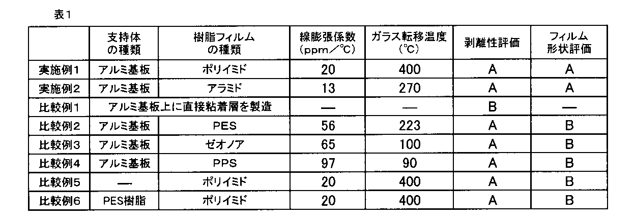
上記表1に示されるように、本発明の基板搬送用キャリアを使用すると、被搬送物の剥離や変形が抑えられる。さらに、粘着層付き樹脂フィルムの反りの発生などが抑制され、結果として被搬送物の位置ずれが生じにくく、電子部品の実装不良の発生が抑制される。
一方、比較例1に示すように、アルミ基板上に直接粘着層を積層した基板搬送用キャリアの場合、被搬送物の剥離の際に、被搬送物の破壊が頻繁に生じた。
また、比較例2~4に示すように、所定の線膨張係数を満たさない樹脂フィルムを使用すると、粘着層付き樹脂フィルムの反り、ゆがみなどが生じていた。これらの結果より所定の線膨張係数を満たす樹脂フィルムでなければ、所望の効果が得られないことが分かった。
また、比較例5に示すように、所定の支持体を使用しなかった場合も、粘着層付き樹脂フィルムの反り、ゆがみなどが生じていた。
さらに、比較例6に示すように、支持体としてポリエーテルサルフォン樹脂を使用した場合も、粘着層付き樹脂フィルムの反り、ゆがみなどを抑制することができなかった。
一方、比較例1に示すように、アルミ基板上に直接粘着層を積層した基板搬送用キャリアの場合、被搬送物の剥離の際に、被搬送物の破壊が頻繁に生じた。
また、比較例2~4に示すように、所定の線膨張係数を満たさない樹脂フィルムを使用すると、粘着層付き樹脂フィルムの反り、ゆがみなどが生じていた。これらの結果より所定の線膨張係数を満たす樹脂フィルムでなければ、所望の効果が得られないことが分かった。
また、比較例5に示すように、所定の支持体を使用しなかった場合も、粘着層付き樹脂フィルムの反り、ゆがみなどが生じていた。
さらに、比較例6に示すように、支持体としてポリエーテルサルフォン樹脂を使用した場合も、粘着層付き樹脂フィルムの反り、ゆがみなどを抑制することができなかった。
また、実施例1で使用された図2に記載の固定手段の代わりに、図5、7、8で示された固定手段を使用した場合も、同様の効果が得られた。
図7および8で示される態様においては、粘着層付き樹脂フィルムの4隅をボルトまたはナットで固定した。
図7および8で示される態様においては、粘着層付き樹脂フィルムの4隅をボルトまたはナットで固定した。
<実施例3および比較例7>
特許文献1を参照して、実施例1で製造した粘着層付きポリイミドフィルムの4隅に耐熱性粘着テープとしてポリイミドテープを張り付け、粘着層付きポリイミドフィルムをアルミ基板に固定し、基板搬送用キャリアを得た。得られた基板搬送用キャリアを、260℃、1分間のリフロー処理し、その後ポリイミドテープを剥がした。その後、剥離された粘着層付きポリイミドフィルムに対して、上記ポリイミドテープによる貼り付け、リフロー処理およびポリイミドテープの剥離という一連の操作を100回繰り返し行った。
100回操作後、基板搬送用キャリアを観察したところ、粘着層付き樹脂フィルムに反り、ゆがみ、または、アルミ基板からの浮きが発生しており、その平坦性が損なわれていることが確認された(比較例7)。
一方、図2、5、7および8で表される本発明の態様に対して、同様の操作(粘着層付きポリイミドフィルムの固定、リフロー処理、および固定手段の解除)を行ったところ、粘着層付き樹脂フィルムに反り、ゆがみ、または、アルミ基板からの浮きが発生していなかった(実施例3)。
特許文献1を参照して、実施例1で製造した粘着層付きポリイミドフィルムの4隅に耐熱性粘着テープとしてポリイミドテープを張り付け、粘着層付きポリイミドフィルムをアルミ基板に固定し、基板搬送用キャリアを得た。得られた基板搬送用キャリアを、260℃、1分間のリフロー処理し、その後ポリイミドテープを剥がした。その後、剥離された粘着層付きポリイミドフィルムに対して、上記ポリイミドテープによる貼り付け、リフロー処理およびポリイミドテープの剥離という一連の操作を100回繰り返し行った。
100回操作後、基板搬送用キャリアを観察したところ、粘着層付き樹脂フィルムに反り、ゆがみ、または、アルミ基板からの浮きが発生しており、その平坦性が損なわれていることが確認された(比較例7)。
一方、図2、5、7および8で表される本発明の態様に対して、同様の操作(粘着層付きポリイミドフィルムの固定、リフロー処理、および固定手段の解除)を行ったところ、粘着層付き樹脂フィルムに反り、ゆがみ、または、アルミ基板からの浮きが発生していなかった(実施例3)。
10,110,210,310,410,510,610,710 基板搬送用キャリア
12,112,212,312,412,512 支持体
14 樹脂フィルム
16 粘着層
18 粘着層付き樹脂フィルム
20、120 押え部材
22,46,42,52 ボルト
24,124 固定手段
26,48 植込みボルト
28,44,50,54 ナット
30 基板
40,140 把持部材
12,112,212,312,412,512 支持体
14 樹脂フィルム
16 粘着層
18 粘着層付き樹脂フィルム
20、120 押え部材
22,46,42,52 ボルト
24,124 固定手段
26,48 植込みボルト
28,44,50,54 ナット
30 基板
40,140 把持部材
Claims (4)
- 基板の搬送に用いられる基板搬送用キャリアであって、
線膨張係数が50ppm/℃以下の樹脂フィルム上に、前記基板の下面と剥離可能に密着する粘着層が設けられた粘着層付き樹脂フィルムと、
金属または金属酸化物で構成された支持体と、
前記粘着層付き樹脂フィルムの前記粘着層のある表面とは反対側の表面と前記支持体の表面とを積層面として、前記粘着層付き樹脂フィルムを前記支持体上に取り外し可能に固定する繰り返し使用可能な固定手段とを備える、基板搬送用キャリア。 - 前記繰返し使用可能な固定手段が、ねじ部材を備える、請求項1に記載の基板搬送用キャリア。
- 前記繰り返し使用可能な固定手段が、前記粘着層付きフィルムと前記支持体とを挟み込んで把持する把持部材を備える、請求項1に記載の基板搬送用キャリア。
- 前記支持体がその表面にねじ穴を有し、
前記固定手段が、前記支持体表面に対して略垂直に延びる縦板部と、前記縦板部の上端から略直交方向に延設し、貫通孔を備える横板部とからなる断面L字状の押し部材、および、前記貫通孔を通り前記ねじ穴に螺合するボルトから構成され、
前記ボルトが前記貫通孔を通り前記ねじ穴に螺合することにより、前記横板部が前記支持体上の粘着層付き樹脂フィルムに当接し、前記支持体上の粘着層付き樹脂フィルムを支持体側に押圧する、請求項1に記載の基板搬送用キャリア。
Applications Claiming Priority (2)
| Application Number | Priority Date | Filing Date | Title |
|---|---|---|---|
| JP2011-018938 | 2011-01-31 | ||
| JP2011018938 | 2011-01-31 |
Publications (1)
| Publication Number | Publication Date |
|---|---|
| WO2012105336A1 true WO2012105336A1 (ja) | 2012-08-09 |
Family
ID=46602555
Family Applications (1)
| Application Number | Title | Priority Date | Filing Date |
|---|---|---|---|
| PCT/JP2012/051201 Ceased WO2012105336A1 (ja) | 2011-01-31 | 2012-01-20 | 基板搬送用キャリア |
Country Status (3)
| Country | Link |
|---|---|
| JP (1) | JP2012178551A (ja) |
| TW (1) | TW201231369A (ja) |
| WO (1) | WO2012105336A1 (ja) |
Cited By (1)
| Publication number | Priority date | Publication date | Assignee | Title |
|---|---|---|---|---|
| CN114537012A (zh) * | 2022-02-22 | 2022-05-27 | 浙江森海新材料股份有限公司 | 一种绿色环保免冲洗双层热敏ctp版材及其生产设备 |
Citations (3)
| Publication number | Priority date | Publication date | Assignee | Title |
|---|---|---|---|---|
| JP2003332795A (ja) * | 2002-05-13 | 2003-11-21 | Daisho Denshi:Kk | 保持搬送用治具及び保持搬送方法 |
| JP2006245205A (ja) * | 2005-03-02 | 2006-09-14 | Shin Etsu Polymer Co Ltd | 電子部品固定治具及び電子部品の加工方法 |
| JP2010161167A (ja) * | 2009-01-07 | 2010-07-22 | Three M Innovative Properties Co | 粘着テープ及び該粘着テープを含む積層体の作製方法 |
-
2012
- 2012-01-20 WO PCT/JP2012/051201 patent/WO2012105336A1/ja not_active Ceased
- 2012-01-20 JP JP2012010163A patent/JP2012178551A/ja not_active Withdrawn
- 2012-01-20 TW TW101102385A patent/TW201231369A/zh unknown
Patent Citations (3)
| Publication number | Priority date | Publication date | Assignee | Title |
|---|---|---|---|---|
| JP2003332795A (ja) * | 2002-05-13 | 2003-11-21 | Daisho Denshi:Kk | 保持搬送用治具及び保持搬送方法 |
| JP2006245205A (ja) * | 2005-03-02 | 2006-09-14 | Shin Etsu Polymer Co Ltd | 電子部品固定治具及び電子部品の加工方法 |
| JP2010161167A (ja) * | 2009-01-07 | 2010-07-22 | Three M Innovative Properties Co | 粘着テープ及び該粘着テープを含む積層体の作製方法 |
Cited By (2)
| Publication number | Priority date | Publication date | Assignee | Title |
|---|---|---|---|---|
| CN114537012A (zh) * | 2022-02-22 | 2022-05-27 | 浙江森海新材料股份有限公司 | 一种绿色环保免冲洗双层热敏ctp版材及其生产设备 |
| CN114537012B (zh) * | 2022-02-22 | 2023-10-27 | 浙江森海新材料股份有限公司 | 一种绿色环保免冲洗双层热敏ctp版材及其生产设备 |
Also Published As
| Publication number | Publication date |
|---|---|
| JP2012178551A (ja) | 2012-09-13 |
| TW201231369A (en) | 2012-08-01 |
Similar Documents
| Publication | Publication Date | Title |
|---|---|---|
| TWI505933B (zh) | The manufacturing method and the layered body of the layered body | |
| JP6303503B2 (ja) | 樹脂組成物、硬化膜、積層フィルム、および半導体装置の製造方法 | |
| US20180281361A1 (en) | Laminate film for temporary bonding, methods for producing substrate workpiece and laminate substrate workpiece using the laminate film for temporary bonding, and method for producing semiconductor device using the same | |
| WO2015129682A1 (ja) | ポリイミド樹脂、これを用いた樹脂組成物および積層フィルム | |
| EP2432010A1 (en) | Manufacturing method of semiconductor device | |
| JP3585904B2 (ja) | 保持搬送用治具 | |
| JP2013138152A (ja) | 搬送治具、搬送方法、および搬送治具材料 | |
| WO2012105336A1 (ja) | 基板搬送用キャリア | |
| WO2013027733A1 (ja) | 基板搬送用キャリアの製造方法および基板搬送用キャリア | |
| WO2022230907A1 (ja) | テープ | |
| WO2012105327A1 (ja) | 基板搬送用キャリアの製造方法、基板搬送用キャリア | |
| CN111094498B (zh) | 有机硅系粘着剂组合物和粘着胶带 | |
| WO2012132969A1 (ja) | 基板搬送用キャリア | |
| JP4097185B2 (ja) | Fpc基板搬送用パレット及びfpc基板への半導体チップ実装方法 | |
| JP4438896B1 (ja) | 搬送キャリアの製造方法 | |
| JP4331047B2 (ja) | 電子部品保持具の製造方法 | |
| JP2014072390A (ja) | 基板搬送用キャリア | |
| JP2014072301A (ja) | 基板搬送用キャリア | |
| JP2014069372A (ja) | 基板搬送用キャリア | |
| JP2005294579A (ja) | 付着防止塗料を有する粘着面で配線基板を固定する治具 | |
| JP2014070118A (ja) | 基板搬送用部材 | |
| JP5636821B2 (ja) | 基板搬送用部材 | |
| JP2004165410A (ja) | クリーム半田塗布方法 | |
| WO2013047532A1 (ja) | 基板搬送用キャリアおよびその製造方法 | |
| KR20040097170A (ko) | Fpc 기판용 반송 팔레트 및 fpc 기판으로의 반도체칩 실장 방법 |
Legal Events
| Date | Code | Title | Description |
|---|---|---|---|
| 121 | Ep: the epo has been informed by wipo that ep was designated in this application |
Ref document number: 12742060 Country of ref document: EP Kind code of ref document: A1 |
|
| NENP | Non-entry into the national phase |
Ref country code: DE |
|
| 122 | Ep: pct application non-entry in european phase |
Ref document number: 12742060 Country of ref document: EP Kind code of ref document: A1 |