WO2012105300A1 - 燃料電池システム - Google Patents
燃料電池システム Download PDFInfo
- Publication number
- WO2012105300A1 WO2012105300A1 PCT/JP2012/050693 JP2012050693W WO2012105300A1 WO 2012105300 A1 WO2012105300 A1 WO 2012105300A1 JP 2012050693 W JP2012050693 W JP 2012050693W WO 2012105300 A1 WO2012105300 A1 WO 2012105300A1
- Authority
- WO
- WIPO (PCT)
- Prior art keywords
- gas
- ejector
- air
- fuel cell
- fuel
- Prior art date
- Legal status (The legal status is an assumption and is not a legal conclusion. Google has not performed a legal analysis and makes no representation as to the accuracy of the status listed.)
- Ceased
Links
Images



Classifications
-
- H—ELECTRICITY
- H01—ELECTRIC ELEMENTS
- H01M—PROCESSES OR MEANS, e.g. BATTERIES, FOR THE DIRECT CONVERSION OF CHEMICAL ENERGY INTO ELECTRICAL ENERGY
- H01M8/00—Fuel cells; Manufacture thereof
- H01M8/04—Auxiliary arrangements, e.g. for control of pressure or for circulation of fluids
- H01M8/04082—Arrangements for control of reactant parameters, e.g. pressure or concentration
- H01M8/04089—Arrangements for control of reactant parameters, e.g. pressure or concentration of gaseous reactants
- H01M8/04097—Arrangements for control of reactant parameters, e.g. pressure or concentration of gaseous reactants with recycling of the reactants
-
- H—ELECTRICITY
- H01—ELECTRIC ELEMENTS
- H01M—PROCESSES OR MEANS, e.g. BATTERIES, FOR THE DIRECT CONVERSION OF CHEMICAL ENERGY INTO ELECTRICAL ENERGY
- H01M8/00—Fuel cells; Manufacture thereof
- H01M8/06—Combination of fuel cells with means for production of reactants or for treatment of residues
- H01M8/0606—Combination of fuel cells with means for production of reactants or for treatment of residues with means for production of gaseous reactants
- H01M8/0612—Combination of fuel cells with means for production of reactants or for treatment of residues with means for production of gaseous reactants from carbon-containing material
- H01M8/0625—Combination of fuel cells with means for production of reactants or for treatment of residues with means for production of gaseous reactants from carbon-containing material in a modular combined reactor/fuel cell structure
-
- Y—GENERAL TAGGING OF NEW TECHNOLOGICAL DEVELOPMENTS; GENERAL TAGGING OF CROSS-SECTIONAL TECHNOLOGIES SPANNING OVER SEVERAL SECTIONS OF THE IPC; TECHNICAL SUBJECTS COVERED BY FORMER USPC CROSS-REFERENCE ART COLLECTIONS [XRACs] AND DIGESTS
- Y02—TECHNOLOGIES OR APPLICATIONS FOR MITIGATION OR ADAPTATION AGAINST CLIMATE CHANGE
- Y02E—REDUCTION OF GREENHOUSE GAS [GHG] EMISSIONS, RELATED TO ENERGY GENERATION, TRANSMISSION OR DISTRIBUTION
- Y02E60/00—Enabling technologies; Technologies with a potential or indirect contribution to GHG emissions mitigation
- Y02E60/30—Hydrogen technology
- Y02E60/50—Fuel cells
Definitions
- the present invention relates to a fuel cell system, and more particularly to a technique for improving the system efficiency of the fuel cell system and reducing the size of the apparatus.
- a fuel cell is a device that generates an electric power by forming an air electrode layer on one side of an electrolyte layer and a fuel electrode layer on the other side, and ions are conducted through the electrolyte layer.
- solid oxide fuel cells (SOFCs) and molten carbonate fuel cells (MCFCs) are known as types of fuel cells in which water (water vapor) is generated at the fuel electrode.
- SOFC solid oxide fuel cells
- MCFCs molten carbonate fuel cells
- Water water vapor
- carbon dioxide carbon dioxide
- electrons are generated. Then, the generated electrons flow through the external circuit, so that electric energy can be taken out.
- an anode off-gas containing steam is introduced into the reformer to perform steam reforming (Patent Document) 2).
- the circulation rate is the ratio (circulation gas amount / anode off gas amount) of the circulating gas (circulation gas) in the anode off gas.
- Patent Document 3 discloses a fuel cell system in which a gas separator is installed on the downstream side of the fuel cell.
- the gas separator separates unused hydrogen and water vapor from the anode off-gas discharged from the anode electrode of the fuel cell, and supplies the separated hydrogen and water vapor to the reformer again via the ejector.
- the ejector injects the driving gas supplied from the driving gas inlet at high speed from the nozzle, thereby generating a negative pressure around the jet and supplying the gas around the jet, specifically, the suction gas inlet. Aspirate the suction gas to be used.
- the suction gas is mixed with the driving gas, pressurized, and discharged from the outlet of the ejector.
- the ejector has a function of converting the kinetic energy of the driving gas into the static pressure of the mixed gas of the suction gas and the driving gas.
- the ratio of the mass flow rate (circulation gas flow rate) G2 of the suction gas to the mass flow rate (drive gas flow rate) G1 of the drive gas is referred to as G2 / G1 ratio.
- the magnitude of this G2 / G1 ratio is determined by the pressure increase amount of the ejector (the pressure of the suction gas supplied from the suction gas inlet (static pressure) and the pressure of the ejector exhaust gas discharged from the outlet of the ejector (static pressure)). Inversely proportional to the difference.
- the ejector sucks suction gas at a circulating gas flow rate G2 determined from a G2 / G1 ratio inversely proportional to the pressure increase amount.
- the drive gas of the ejector is a fuel gas and the suction gas is a circulating gas that is a part of the anode off gas
- the circulation rate is increased in order to improve the reforming rate in the reformer
- G2 The / G1 ratio needs to be increased.
- the G2 / G1 ratio may not be increased to a desired value because the boosting capability of the ejector is limited.
- the circulation gas may not be sufficiently boosted.
- the pressure increase amount of the ejector is increased in order to reduce the size of the reformer and the fuel cell, the circulating gas flow rate G2 is limited, and the amount of steam supplied to the reformer is insufficient.
- the catalyst may deteriorate due to a decrease in the mass ratio or carbon deposition due to a disproportionation reaction.
- the G2 / G1 ratio is reduced to increase the amount of pressurization of the ejector, and it is necessary for the reformer.
- the amount of water vapor can be supplied.
- this gas separator separates water vapor and hydrogen by the difference between the gas pressure on the inlet side and the gas pressure on the outlet side of the gas separator. Therefore, there is a large gas pressure difference before and after the separator. Necessary. Therefore, it is difficult to reduce the size of the fuel cell and the reformer, the system is enlarged, and complicated control such as pressure control for separating water vapor and hydrogen is required.
- the present invention has been made in order to solve the above-described problems.
- the object of the present invention is to increase the boosting amount of the ejector to improve the efficiency of the entire system, and to reduce the size of the fuel cell and the reformer. It is an object of the present invention to provide a fuel cell system capable of achieving the above.
- One embodiment of the present invention includes an air supply device that supplies air, a fuel gas supply device that supplies fuel gas, a reformer that generates reformed gas containing hydrogen from the fuel gas, and a reformed gas at the anode electrode A fuel cell in which air is supplied to the cathode electrode to generate electricity, and water vapor is generated in the anode electrode, and a recirculation system for circulating the anode off-gas discharged from the anode electrode of the fuel cell to the reformer, And a fuel cell system.
- the recirculation system includes an ejector, and a mixed gas obtained by mixing the air sent from the air supply device and the fuel gas sent from the fuel gas supply device is supplied to the drive gas inlet of the ejector. An anode off gas is supplied to the inlet.
- FIG. 1 is a block diagram showing the configuration of the fuel cell system according to the first embodiment of the present invention.
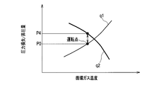
- FIG. 2 is a characteristic diagram showing the relationship between the circulating gas temperature, the system pressure loss, and the ejector pressure increase amount in the fuel cell system according to the first embodiment of the present invention.
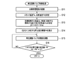
- FIG. 3 is a flowchart showing a procedure of control processing of the back pressure adjustment valve in the fuel cell system according to the first embodiment of the present invention.
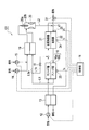
- FIG. 4 is a block diagram showing the configuration of the fuel cell system according to the second embodiment of the present invention.
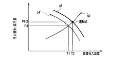
- FIG. 5 is a characteristic diagram showing the relationship between the circulating gas temperature, the total system pressure loss, and the ejector pressure increase amount in the fuel cell system according to the second embodiment of the present invention.
- FIG. 1 is a block diagram showing the configuration of the fuel cell system according to the first embodiment of the present invention.
- FIG. 2 is a characteristic diagram showing the relationship between the circulating gas temperature, the system pressure loss, and the ejector pressure increase amount
- FIG. 6 is a flowchart showing a control processing procedure of the second air compressor and the additional air adjustment valve in the fuel cell system according to the second embodiment of the present invention.
- FIG. 7 is a block diagram showing the configuration of the fuel cell system according to the third embodiment of the present invention.
- FIG. 8 is a characteristic diagram showing the relationship between the circulating gas temperature, the total system pressure loss, and the ejector pressure increase amount in the fuel cell system according to the third embodiment of the present invention.
- FIG. 9 is a flowchart showing the procedure of the cooling air control process in the fuel cell system according to the third embodiment of the present invention.
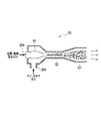
- FIG. 10 is an explanatory diagram showing the configuration of the ejector used in the fuel cell system according to the embodiment of the present invention.
- FIG. 1 is a block diagram showing a configuration of a fuel cell system 100 according to the first embodiment of the present invention.
- the fuel cell system 100 includes a fuel cell 16 having a cathode 16a and an anode 16b, a reformer 22 that reforms hydrocarbon fuel to generate a reformed gas, and a reformer.
- fuel gas hydrogen gas, natural gas mainly composed of methane (CH 4 ), or the like can be used.
- fuel gas atomized liquid fuels such as bioethanol, gas liquefied oil (GTL), coal liquefied oil (CTL), biomass liquefied oil (BTL), etc., propane, butane, gasoline, diesel, kerosene, etc. Things can also be used.
- the reformer 22 is a heat self-supporting reformer having a heat insulating structure that does not include the reforming heater 21, and can be reacted in an autothermal reforming (ATR) mode in which air and steam are introduced.
- the reformer 22 is a heat exchanger type reformer that exchanges a part of the heat necessary for reforming from the reforming heater 21 that burns the remainder of the anode off-gas, and is an air-added steam reforming mode. Can also be reacted.
- the fuel cell system 100 uses the first air blower 12 for supplying air to the cathode electrode 16 a of the fuel cell 16 and the heat of the exhaust gas exhausted from the reforming heater 21 from the first air blower 12.
- a third heat exchanger 13 for heating the supplied air a second air compressor 14 (air supply device) for sending air, a fuel pump 15 (fuel gas supply device) for sending fuel gas, and a first heat And an exchanger 19 (temperature controller).
- the fuel cell 16 generates electric power by reacting the air supplied to the cathode electrode 16a (the air heated by the third heat exchanger 13) and the reformed gas supplied to the anode electrode 16b. Power is supplied to (not shown). Therefore, in the fuel cell 16, water (water vapor) is generated in the anode electrode 16b, and the anode off-gas discharged from the anode electrode 16b contains water vapor.
- the outlet of the anode 16b is connected to the flow path L1, and the flow path L1 is further branched into two flow paths L1a and L1b, and one of the flow paths L1a is the back pressure adjustment valve 17 (circulation amount regulator). )
- the other flow path L1b is connected to the gas supply port of the reforming heater 21 via the butterfly valve 18. Further, the outlet on the high temperature side of the first heat exchanger 19 is connected to the suction gas inlet 20 b of the ejector 20.
- Both the outlet of the second air compressor 14 and the outlet of the fuel pump 15 are connected to the low temperature side inlet of the first heat exchanger 19, and the outlet is connected to the drive gas inlet 20 a of the ejector 20. Therefore, the mixed gas in which the air supplied from the second air compressor 14 and the fuel gas supplied from the fuel pump 15 are mixed is heated by passing through the low temperature side of the first heat exchanger 19, and then The high-pressure driving gas is supplied to the driving gas inlet 20a of the ejector 20.
- the anode off gas discharged from the anode electrode 16b of the fuel cell 16 passes through the high temperature side of the first heat exchanger 19 and transfers heat to the mixed gas, and then as a circulating gas, the suction gas inlet of the ejector 20 20b. Further, the remainder of the anode off gas (anode off gas that does not become a circulating gas) is supplied to the reforming heater 21 via the flow path L1b and the butterfly valve 18.
- the ejector 20 sucks the suction gas supplied to the suction gas inlet 20b by the pressure of the drive gas supplied to the drive gas inlet 20a, and mixes the drive gas and the suction gas at a predetermined pressure increase amount.
- the mixed gas discharged from the outlet of the ejector 20 is a mixed gas of air, fuel gas, and anode off gas, and is called ejector exhaust gas.
- a mixed gas of air and fuel gas is supplied as a driving gas to the driving gas inlet 20a, and an anode off-gas (circulation gas) is supplied to the suction gas inlet 20b.
- the anode off-gas is sucked and increased by the pressure of the driving gas, and a gas (ejector exhaust gas) mixed with the anode off-gas is discharged from the ejector 20.
- the ejector exhaust gas is supplied to the reformer 22 via the flow path L2.
- the anode 16b of the fuel cell 16 the back pressure adjustment valve 17, the first heat exchanger 19, the ejector 20, the reformer 22, and the flow paths L1, L1a, L2, and the like are anode off-gas. This constitutes a recirculation system that circulates the fuel to the reformer 22.
- the air sent from the first air blower 12 is supplied to the low temperature side, and the exhaust gas of the reforming heater 21 is supplied to the high temperature side. Therefore, the air sent from the first air blower 12 is heated by the exhaust gas of the reforming heater 21 and then supplied to the cathode electrode 16 a of the fuel cell 16. The exhaust gas that has passed through the third heat exchanger 13 is then discharged to the outside.
- the reformer 22 includes a pressure sensor 23 that detects an inlet pressure (reformer pressure) Pr of the reformer 22 and a reformer temperature that measures a temperature (reformation temperature) Tr of the reformer 22.
- a sensor 24 is provided.
- the fuel cell 16 is provided with a stack temperature sensor 25 that measures the stack temperature Ts of the fuel cell 16.
- the fuel cell system 100 includes a control unit 11 that controls the first air blower 12, the second air compressor 14, the fuel pump 15, and the back pressure adjustment valve 17.
- the control part 11 transmits a control signal to the 1st air blower 12, the 2nd air compressor 14, the fuel pump 15, and the back pressure adjustment valve 17 with the method mentioned later.
- the control unit 11 is connected to the pressure sensor 23, the reformer temperature sensor 24, and the stack temperature sensor 25, and acquires detection data of each of these sensors.
- the controller 11 is based on the reformer pressure Pr measured by the pressure sensor 23, the reforming temperature Tr measured by the reformer temperature sensor 24, and the stack temperature Ts measured by the stack temperature sensor 25. Then, the circulation amount of the anode off gas is obtained. And the control part 11 controls the opening degree of the back pressure adjustment valve 17 based on the calculated
- FIG. 10 is a cross-sectional view of the ejector 20.
- the ejector 20 includes a nozzle 51 at the center, and the base end of the nozzle 51 is a drive gas inlet 20a.
- a cylindrical space region is formed on the side of the nozzle 51, and a part of this space region is opened to serve as the suction gas inlet 20b.
- the space area and the nozzle 51 have a double cylindrical structure, and a mixing section 52 and a diffuser 53 are provided on the downstream side thereof.
- the mixed gas is jetted from the nozzle 51 to become a high-speed flow, and the anode off-gas is sucked from the suction gas inlet 20b.
- the sucked anode off gas is mixed with the mixed gas of air and fuel gas, which is the driving gas, in the mixing section 52, and the flow rate is made uniform, so that the pressure is increased from before the mixing.
- the average flow velocity is further reduced and increased until reaching the end of the subsequent diffuser 53, and supplied to, for example, the reformer 22 shown in FIG.
- the stack temperature Ts of the fuel cell 16 and the system pressure loss, and the relationship between the circulating gas temperature and the pressure increase amount of the ejector will be described.
- the stack temperature Ts and the circulating gas temperature are assumed to be equal.
- FIG. 2 is a characteristic diagram showing the relationship between the system pressure loss and the pressure increase amount of the ejector 20 with respect to changes in the circulating gas temperature.
- a curve q1 indicates a change in the system pressure loss
- a curve q2 indicates a change in the pressure increase amount of the ejector 20.
- the system pressure loss here is the pressure loss during which the ejector exhaust gas flows from the outlet of the ejector 20 to the suction gas inlet 20b via the reformer 22, the anode 16b, and the first heat exchanger 19. From this, the pressure loss at the back pressure adjusting valve 17 is removed.
- the pressure loss including the pressure loss at the back pressure adjusting valve 17 is distinguished from the system pressure loss and is called total system pressure loss.
- the total system pressure loss refers to a pressure loss during which the ejector exhaust gas flows from the outlet of the ejector 20 to the suction gas inlet 20b via each component of the recirculation system.
- the system pressure loss increases as the stack temperature Ts increases.
- the fuel cell system 100 is operated at any point on the characteristic curve q1.
- the curve q2 indicates a desired ratio of the mass flow rate of the drive gas (hereinafter referred to as drive gas flow rate) G1 and the mass flow rate of the suction gas (hereinafter referred to as circulation gas flow rate) G2 in the ejector 20, that is, the G2 / G1 ratio.
- drive gas flow rate the mass flow rate of the drive gas
- circulation gas flow rate the mass flow rate of the suction gas
- the fuel cell system 100 is operated at an operating point where the value of the system pressure loss excluding the pressure loss at the back pressure adjustment valve 17 is P0.
- the pressure increase amount P ⁇ b> 4 in the ejector 20 is set to a flow rate required for good reforming by the reformer 22 for each flow rate of air, fuel gas, and anode off-gas circulating gas. Sometimes it is designed to be larger than the system pressure loss P0. Then, the opening degree of the back pressure adjustment valve 17 is adjusted so that the value of the total system pressure loss including the pressure loss at the back pressure adjustment valve 17 coincides with the pressure increase amount P4.
- the ejector 20 has a boosting capability to obtain a boosting amount P4 that is slightly higher than the value P0 of the system pressure loss (excluding the pressure loss at the back pressure adjusting valve 17) at the operating point.
- the mass flow rate (henceforth, air quantity) of the air sent from the 2nd air compressor 14 is adjusted so that G2 / G1 ratio may become a desired value.
- step S ⁇ b> 11 the control unit 11 recognizes a target generated current by the fuel cell 16.
- step S12 the control unit 11 acquires the stack temperature Ts of the fuel cell 16 measured by the stack temperature sensor 25 and the reforming temperature Tr of the reformer 22 measured by the reformer temperature sensor 24.
- step S ⁇ b> 13 the control unit 11 determines the target circulating gas flow rate G ⁇ b> 2 based on the acquired information such as the target generated current and the stack temperature, and the mass flow rate of fuel gas newly supplied to the reformer 22 (hereinafter referred to as fuel).
- Gas amount) G1f and air amount G1a are determined.
- step S14 the control unit 11 calculates the target value P4 of the boost amount corresponding to the ratio (G2 / G1 ratio) between the drive gas flow rate G1 and the circulating gas flow rate G2 in the ejector 20.
- step S ⁇ b> 15 the control unit 11 transmits a control signal to the back pressure adjustment valve 17 so that the total system pressure loss including the pressure loss at the back pressure adjustment valve 17 reaches the target value P ⁇ b> 4 of the pressure increase amount of the ejector 20.
- the opening degree of the back pressure adjusting valve 17 is controlled. Thereby, the circulation amount of anode off gas is adjusted.
- the opening of the back pressure adjustment valve 17 the total system pressure loss is reduced while ensuring the flow rates of the circulating gas of the air, fuel gas, and anode off gas required by the reformer 22 and the fuel cell 16. Control is performed so as to be equal to the pressure increase amount P4 of the ejector 20.
- the fuel cell system 100 when a part of the anode off-gas is circulated and returned to the reformer 22, a mixed gas of air and fuel gas is generated and converted into the anode off-gas. It is added.
- the fuel since air is added to the drive gas of the ejector 20 in addition to the fuel gas, the fuel has a relatively large molecular weight such as gasoline, kerosene, methanol, etc., and the specific heat ratio Therefore, even when using a hydrocarbon fuel that causes a large heat loss in the flow in the ejector, the boosting capability of the ejector 20 can be reliably maintained high.
- the first heat exchanger 19 that adjusts the temperature of the anode off-gas is provided between the outlet of the anode 16b and the suction gas inlet 20b of the ejector 20. Provided. Then, at least one of air sent from the second air compressor 14 and fuel gas sent from the fuel pump 15 is supplied to the low temperature side of the first heat exchanger 19, and to the high temperature side of the first heat exchanger 19. The anode off gas is supplied. Therefore, the heat of the anode off gas can heat the air sent from the second air compressor 14 or the fuel gas sent from the fuel pump 15, so that the temperature of the circulating anode off gas can be stabilized. it can.
- the circulating gas temperature can be stabilized and the circulation rate can be stabilized. Further, when the fuel gas is supplied from a liquid or a high-pressure tank, no extra energy is required and the fuel gas can be vaporized stably.
- the back pressure adjusting valve 17 is provided, and the control unit 11 adjusts and controls the opening degree of the back pressure adjusting valve 17, thereby controlling the circulation amount of the anode off gas and the ejector.
- the amount of pressure increase at 20 is controlled to a desired value. That is, the control unit 11 adjusts and controls the opening degree of the back pressure adjustment valve 17 in accordance with the pressure increase amount of the ejector 20, so that the pressure of the gas introduced into the reformer 22 can be set to a desired pressure.
- the pressure increase amount of the ejector 20 can be improved, the fuel cell 16 and the reformer 22 can be designed with a reduced size.
- the control unit 11 adjusts and controls the opening degree of the back pressure adjustment valve 17, so that the pressure loss in the back pressure adjustment valve 17.
- the total system pressure loss including can be stabilized.
- FIG. 4 is a block diagram showing the configuration of the fuel cell system 101 according to the second embodiment.
- This fuel cell system 101 is not provided with a back pressure adjustment valve 17, and an air supply port d1 is provided in a flow path L2 connecting the outlet of the ejector 20 and the inlet of the reformer 22, and is sent from the second air compressor.
- an additional air adjustment valve 31 air supply device
- the air supply port d1 By adjusting the amount of air introduced more, the amount of air supplied to the reformer 22 can be adjusted, and the additional air adjustment valve 31 and the control unit 11 are connected by a control line. This is different from the fuel cell system 100 (FIG. 1) according to the first embodiment.
- control unit 11 includes an air amount, a fuel gas amount, an anode off-gas circulation amount, and an ejector that are supplied to the reformer 22 based on a required power generation output of the fuel cell input from the outside.
- a boost amount of 20 is obtained.
- control unit 11 adjusts the additional air based on the obtained air amount, fuel gas amount, anode off-gas circulation amount, ejector 20 pressure increase amount, and reformer pressure Pr measured by the pressure sensor 23.
- a function of controlling the amount of air supplied by the valve 31 is provided.
- the ejector 20 is designed so that the pressure increase amount matches the total system pressure loss when air and fuel gas having a flow rate smaller than the air amount required by the reformer 22 during rated operation are used as driving gas.
- the air amount G1a1 is adjusted so that the pressure increase amount of the ejector 20 matches the total system pressure loss. Since the air amount G1a1 is deficient by “G1a ⁇ G1a1” from the air amount G1a required for reforming in the reformer 22, the air amount G1a2, which is the difference, is passed through the additional air adjustment valve 31. Directly supplied to the reformer 22.
- FIG. 5 is a characteristic diagram showing the relationship between the circulating gas temperature and the total system pressure loss (curve q3) and the relationship between the circulating gas temperature and the pressure increase amount of the ejector 20 (curves q4 and q4 ').
- the fuel cell system 101 is operating at a point where the circulating gas temperature is T1 and the total system pressure loss / ejector pressure increase amount is P4.
- the stack temperature Ts of the fuel cell 16 rises and the circulating gas temperature becomes T2
- the total system pressure loss rises along the curve q3, and the required boost amount of the ejector 20 is also P4-2. To rise.
- the air amount G1a1 supplied from the second air compressor 14 is increased, and the G2 / G1 ratio is decreased.
- the characteristic curve of the pressure increase amount of the ejector 20 changes from the curve q4 ′ to the curve q4. Therefore, the pressure increase amount of the ejector 20 can be set to the value P4-2 required by the system. It becomes possible to operate at the operating point of the system pressure loss / ejector boosting amount P4-2.
- the amount of air G1a1 supplied as the drive gas for the ejector 20 increases.
- the amount of increase in the amount of air is supplied via the additional air adjustment valve 31.
- the amount of air G1a2 to be reduced is decreased. Thereby, the amount of air supplied to the reformer 22 is adjusted.
- the ejector 20 is designed so as to satisfy the required boosting performance when the air amount G1a1 smaller than the air amount G1a required by the reformer 22 is introduced into the ejector 20. Then, the air amount G1a1 supplied from the second air compressor 14 and the air amount G1a2 supplied via the additional air adjustment valve 31 are adjusted according to the change in the total system pressure loss, and supplied to the reformer 22. Control the temperature and pressure of the gas to be the desired values.
- step S ⁇ b> 31 the control unit 11 recognizes a target generated current by the fuel cell 16.
- step S32 the control unit 11 acquires the stack temperature Ts of the fuel cell 16 measured by the stack temperature sensor 25 and the reforming temperature Tr of the reformer 22 measured by the reformer temperature sensor 24.
- step S ⁇ b> 33 the control unit 11 determines the target circulating gas flow rate G ⁇ b> 2, the fuel gas amount G ⁇ b> 1 f that is newly supplied to the reformer 22, and the newly supplied air based on the acquired information such as the target generated current and stack temperature.
- the quantity G1a is determined.
- step S34 the control unit 11 calculates a target value P4 of the boost amount of the ejector 20 corresponding to the stack temperature Ts.
- step S35 the controller 11 supplies the circulating gas flow rate G2, the air amount G1a1 supplied by the second air compressor 14, and the air supplied via the additional air adjustment valve 31 to the target value P4 obtained in step S34.
- step S36 the controller 11 adjusts the second air compressor 14 so that the amount of air supplied from the second air compressor 14 becomes the air amount G1a1 determined in step S35. Further, the opening degree of the additional air adjustment valve 31 is adjusted so that the amount of air supplied from the additional air adjustment valve 31 becomes the air amount G1a2 determined in step S35.
- an air supply port d1 is provided in the flow path L2 connecting the outlet of the ejector 20 and the inlet of the reformer 22, and additional air adjustment is performed in the air supply port d1.
- air is introduced into the reformer 22 separately from the operating state of the ejector 20. Therefore, even if temperature fluctuations or gas flow rate fluctuations of the fuel cell 16 or the reformer 22 occur during operation, the circulation rate of the anode off gas can be stabilized.
- the control unit 11 determines whether the ejector exhaust gas discharged from the ejector 20 is circulated to the suction gas inlet 20b of the ejector 20 according to the pressure loss. Since the additional air adjustment valve 31 is adjusted, the composition of the gas introduced into the reformer 22 can be set to an optimum composition. Thereby, carbon deposition deterioration of the reformer 22 can be suppressed.
- the power of the second air compressor 14 can be minimized, and the reformer 22 is required even when the required power generation output in the fuel cell 16 changes.
- the gas composition to be can be stably supplied.
- FIG. 7 is a block diagram showing the configuration of the fuel cell system 102 according to the third embodiment.
- the fuel cell system 102 does not include the back pressure adjustment valve 17, and the second heat exchanger 41 is provided in the flow path L1a between the high temperature side outlet of the first heat exchanger 19 and the suction gas inlet 20b of the ejector 20.
- (Temperature regulator) provided, third air blower 42 (cooling gas supplier, temperature regulator) for supplying cooling air to the low temperature side of the second heat exchanger 41, and third It differs from the fuel cell system 100 (FIG. 1) according to the first embodiment described above in that the air blower 42 and the control unit 11 are connected by a control line.
- control unit 11 is configured such that the amount of air supplied to the reformer 22, the amount of fuel gas, the circulation amount of anode off gas, and the ejector based on the required power generation output of the fuel cell input from the outside. A boost amount of 20 is obtained. Then, the control unit 11 controls the ejector 20 based on the obtained air amount, fuel gas amount, anode off-gas circulation amount, the pressure increase amount of the ejector 20, and the reformer pressure Pr measured by the pressure sensor 23. The temperature of the supplied anode off gas is determined. Furthermore, the control part 11 controls the 3rd air blower 42 according to the calculated
- control unit 11 controls the amount of air supplied by the third air blower 42 to be supplied to the ejector 20. It is possible to adjust the temperature of the anode off gas.
- the value P4 of the total system pressure loss (mainly pressure loss in the pipes constituting the reformer 22, the fuel cell 16, and the flow paths L1, L1a, and L2) corresponding to the stack temperature Ts during rated operation is calculated.
- the circulating gas flow rate G2 and the driving gas flow rate G1 required for power generation and reforming are used. And calculate.
- the temperature of the anode off gas immediately before being sucked into the ejector 20 depends on the heat insulating performance of a pipe or the like that becomes a flow path from the outlet of the anode electrode 16b of the fuel cell 16 to the suction gas inlet 20b of the ejector 20. It can be set as a temperature proportional to the stack temperature Ts.
- the ejector 20 is designed so that the pressure increase amount of the ejector 20 matches the total system pressure loss P4 during the rated operation when the temperature of the anode off gas immediately before being sucked into the ejector 20 reaches the temperature T3 during the rated operation. To do.
- FIG. 8 is a characteristic diagram showing changes in the total system pressure loss with respect to changes in the circulating gas temperature (curve q5), and changes in the ejector pressure increase amount with respect to changes in the circulating gas temperature (curves q6, q6 ').
- curve q5 changes in the total system pressure loss with respect to changes in the circulating gas temperature
- curves q6, q6 ' changes in the ejector pressure increase amount with respect to changes in the circulating gas temperature
- the pressure increase amount of the ejector 20 can be maintained with the same G2 / G1 ratio. Can be changed.
- the pressure increase amount of the ejector 20 becomes the value P4 during rated operation by adjusting the flow rate of the cooling gas delivered from the third air blower 42 and cooling the circulating gas under the control of the control unit 11. To control.
- step S51 the control unit 11 recognizes a target generated current by the fuel cell 16.
- step S52 the control unit 11 acquires the stack temperature Ts of the fuel cell 16 measured by the stack temperature sensor 25 and the reforming temperature Tr of the reformer 22 measured by the reformer temperature sensor 24.
- step S ⁇ b> 53 the control unit 11 determines the target circulating gas flow rate G ⁇ b> 2, the fuel gas amount G ⁇ b> 1 f to be newly supplied to the reformer 22, and the newly supplied air based on the acquired information such as the target generated current and the stack temperature.
- the quantity G1a is determined.
- step S54 the control unit 11 calculates a target value P4 of the boost amount corresponding to the stack temperature Ts and the reforming temperature Tr.
- step S55 the control unit 11 realizes the target value P4 of the boosted amount obtained in step S54, and the circulating gas flow rate G2 and the driving gas flow rate G1 (the sum of the fuel gas amount G1f and the air amount G1a) obtained in step S53.
- a temperature T3 of the anode off gas for performing the calculation is calculated.
- step S56 the control unit 11 adjusts the amount of cooling air sent from the third air blower 42 so that the temperature of the anode off gas becomes the temperature T3 calculated in step S55.
- the second heat exchanger 41 that adjusts the temperature of the anode off-gas is provided between the outlet of the anode 16b and the suction gas inlet 20b of the ejector 20. Yes.
- the cooling air sent from the third air blower 42 is supplied to the low temperature side of the second heat exchanger 41, and the anode off gas is supplied to the high temperature side of the second heat exchanger 41.
- the amount of pressure increase of the ejector 20 can be changed with the same G2 / G1 ratio. .
- the control unit 11 controls the third air blower 42 according to the pressure loss while the ejector exhaust gas discharged from the ejector 20 circulates to the suction gas inlet 20 b of the ejector 20.
- the flow rate of the cooling gas sent out is adjusted, the temperature of the circulating gas is adjusted, and the pressure increase amount of the ejector 20 is controlled to a desired value. Therefore, even when the temperature of the circulating gas changes, the pressure increase amount of the ejector 20 can be maintained at a desired value, and the circulation amount of the anode off gas can be stabilized. As a result, the reforming reaction of the reformer 22, and thus the power generation behavior of the stack can be stabilized.
- the air supply port d1 and the additional air adjustment valve 31 of the second embodiment may be employed in the fuel cell system 100 of the first embodiment, and the fuel cell system 101 of the second embodiment may be employed in the third embodiment.
- the second heat exchanger 41 and the third air blower 42 may be employed.
- the back pressure regulating valve 17 of the first embodiment may be adopted for the fuel cell system 102 of the third embodiment, and all the components of the first to third embodiments can be applied in combination. is there.
- the second air compressor 14 is connected to the drive gas inlet 20a of the ejector 20 via the first heat exchanger 19, but the first heat exchanger 19 It may be directly connected to the drive gas inlet 20a of the ejector 20 without going through. That is, the outlet of the second air compressor 14 is connected to a flow path between the outlet of the first heat exchanger 19 and the driving gas inlet 20a of the ejector 20 instead of the low temperature side inlet of the first heat exchanger 19. May be.
- the drive gas flow rate G1 can be increased, and the G2 / G1 ratio of the ejector can be reduced.
- the carbon deposition deterioration of the reformer and the reduction in the reforming rate can be suppressed, the ejector pressure increase can be increased to improve the overall system efficiency, and the fuel cell and reformer can be made smaller.
Landscapes
- Life Sciences & Earth Sciences (AREA)
- Sustainable Development (AREA)
- Engineering & Computer Science (AREA)
- Manufacturing & Machinery (AREA)
- Sustainable Energy (AREA)
- Chemical & Material Sciences (AREA)
- Chemical Kinetics & Catalysis (AREA)
- Electrochemistry (AREA)
- General Chemical & Material Sciences (AREA)
- Fuel Cell (AREA)
Abstract
空気を供給する空気供給器(14)と、燃料ガスを供給する燃料ガス供給器(15)と、燃料ガスから水素を含む改質ガスを生成する改質器(22)と、アノード極(16b)に改質ガスが供給され、カソード極(16a)に空気が供給されて発電し、かつ、アノード極(16b)に水蒸気が発生する燃料電池(16)と、燃料電池(16)のアノード極(16b)より排出されるアノードオフガスを改質器(22)へ循環させる再循環系と、を有する燃料電池システム(100,101,102)である。再循環系は、エゼクタ(20)を備え、エゼクタ(20)の駆動ガス流入口(20a)には、空気供給器(14)より送出される空気と燃料ガス供給器(15)により送出される燃料ガスとを混合した混合ガスが供給され、吸引ガス流入口(20b)には、アノードオフガスが供給される。
Description
本発明は、燃料電池システムに係り、特に、燃料電池システムのシステム効率を向上させ、かつ装置を小型化する技術に関する。
近年、水素と酸素との化学反応を利用して電力を発生する燃料電池が注目を集めている。燃料電池は、電解質層の一方に空気極層、他方に燃料極層を形成し、電解質層をイオンが伝導することにより電力を発生させる装置である。また、燃料極に水(水蒸気)が生成されるタイプの燃料電池として、固体酸化物形燃料電池(SOFC)や溶融炭酸塩型燃料電池(MCFC)が知られている。例えば、SOFCでは、空気極にて空気が反応して酸素イオンが生成され、この酸素イオンが電解質中を伝導して燃料極に到達し、燃料極にて水素や一酸化炭素と反応することで、水(水蒸気)、二酸化炭素、及び電子が生成される。そして、生成された電子が外部回路を流れることによって、電気エネルギーを取り出すことが可能になる。
燃料極に水が生成される燃料電池を備えた燃料電池システムでは、燃料電池で消費されずに排出される未反応の水素を含有するガス(以下、アノードオフガスという)を、新たな燃料ガスと混合して再度燃料電池に供給する技術が提案されている(特許文献1参照)。
また、燃料極に水が生成される燃料電池と改質器とを備えた燃料電池システムでは、水蒸気を含有するアノードオフガスを改質器に導入して水蒸気改質を行うこともある(特許文献2参照)。このような燃料電池システムでは、燃料電池の動作温度を低温化させることができるようになった場合でも、改質器での改質率を低下させないために、循環率を向上させることが重要になる。循環率とは、アノードオフガスのうち循環するガス(循環ガス)の比率(循環ガス量/アノードオフガス量)である。
特許文献3は、燃料電池の下流側にガス分離器を設置した燃料電池システムを開示している。この燃料電池システムでは、ガス分離器によって、燃料電池のアノード電極より排出されたアノードオフガスから未使用の水素及び水蒸気を分離し、分離した水素及び水蒸気を、エゼクタを介して再度改質器に供給する。エゼクタは、駆動ガス流入口から供給される駆動ガスをノズルから高速で噴射することで、その噴流周りに負圧を発生させ、その噴流周りのガス、具体的には、吸引ガス流入口から供給される吸引ガスを吸引する。吸引ガスは、駆動ガスと混合されて昇圧され、エゼクタの出口から排出される。
ここでエゼクタは、駆動ガスの運動エネルギーを、吸引ガス及び駆動ガスの混合ガスの静圧に変換する機能を備えている。駆動ガスの質量流量(駆動ガス流量)G1に対する吸引ガスの質量流量(循環ガス流量)G2の比率をG2/G1比という。このG2/G1比の大きさは、エゼクタの昇圧量(吸引ガス流入口から供給される吸引ガスの圧力(静圧)とエゼクタの出口から排出されるエゼクタ排出ガスの圧力(静圧)との差)に反比例する。エゼクタは、駆動ガス流量G1が設定され、かつ後述する全システム圧損に相当する要求昇圧量が決まると、この昇圧量に反比例するG2/G1比から定まる循環ガス流量G2で、吸引ガスを吸引する。
エゼクタの駆動ガスを燃料ガスとし、吸引ガスをアノードオフガスの一部である循環ガスとする燃料電池システムにおいて、改質器での改質率を向上させるために循環率を高める場合には、G2/G1比を大きくする必要がある。しかし、駆動ガスとして燃料ガスのみを用いる場合には、エゼクタの昇圧能力に限界があるため、G2/G1比を所望の値まで大きくすることができない場合がある。
例えば、燃料ガスのみを駆動ガスとして循環ガスを吸引する場合において、循環率を50%以上とする場合には、循環ガスを十分に昇圧できないことがある。この場合は、昇圧量の不足分を、改質器及び燃料電池での圧力損失を低減することで補うために、改質器及び燃料電池を大型化せざるを得なくなる。一方、改質器及び燃料電池を小型化するために、エゼクタの昇圧量を大きくしようとすれば、循環ガス流量G2に限界が生じ、改質器に供給される水蒸気の量が不足して改質率が低下したり、不均化反応による炭素析出等によって触媒が劣化する恐れがある。
なお、特許文献3のシステムのように、アノードオフガスから水素及び水蒸気のみを分離して循環させれば、G2/G1比を小さくしてエゼクタの昇圧量を大きくし、かつ改質器に必要な水蒸気量を供給できる可能性はある。しかし、このガス分離器は、ガス分離器の入口側のガス圧力と出口側のガス圧力との差によって水蒸気及び水素を分離するものであり、そのために、分離器の前後で大きなガス圧力差が必要となる。従って、燃料電池や改質器を小型化することが困難となり、システムが大型化し、水蒸気及び水素を分離するための圧力制御など複雑な制御が必要となる。
また、特許文献3のシステムにおいて、アノードオフガスの循環率を大きく設定すると、アノードオフガスの残部(循環させない分)の流量が減少して、改質器を加熱するための加熱器による発熱量が不足する。この場合、加熱器に追加燃料を導入することが必要となり、結局、システム効率が低下する。
一方、アノードオフガスの循環率を低く設定して、改質器で不足する水蒸気を追加で導入する場合には、水蒸気を生成して導入するために追加的なエネルギーが必要となり、やはりシステム効率が低下する。
上述したように、特許文献3に記載された技術によれば、アノードオフガスの循環率を高めると、燃料ガスのみを駆動ガスとしたエゼクタの昇圧能力に限界が生じるので、その分、改質器及び燃料電池が大型化する。
本発明は、上記課題を解決するためになされたものであり、その目的とするところは、エゼクタの昇圧量を高めてシステム全体の効率を向上させ、かつ、燃料電池及び改質器の小型化を図ることが可能な燃料電池システムを提供することにある。
本発明の一態様は、空気を供給する空気供給器と、燃料ガスを供給する燃料ガス供給器と、燃料ガスから水素を含む改質ガスを生成する改質器と、アノード極に改質ガスが供給され、カソード極に空気が供給されて発電し、かつ、アノード極に水蒸気が発生する燃料電池と、燃料電池のアノード極より排出されるアノードオフガスを改質器へ循環させる再循環系と、を有する燃料電池システムである。再循環系は、エゼクタを備え、エゼクタの駆動ガス流入口には、空気供給器より送出される空気と燃料ガス供給器により送出される燃料ガスとを混合した混合ガスが供給され、吸引ガス流入口には、アノードオフガスが供給される。
以下、本発明の実施形態を図面に基づいて説明する。
<第1実施形態>
図1は、本発明の第1実施形態に係る燃料電池システム100の構成を示すブロック図である。図1に示すように、この燃料電池システム100は、カソード極16aおよびアノード極16bを有する燃料電池16と、炭化水素燃料を改質して改質ガスを発生する改質器22と、改質器22を加熱する改質加熱器21と、空気、燃料ガス、及びアノードオフガスを混合したガスを改質器22に昇圧して供給するエゼクタ20と、を備えている。
図1は、本発明の第1実施形態に係る燃料電池システム100の構成を示すブロック図である。図1に示すように、この燃料電池システム100は、カソード極16aおよびアノード極16bを有する燃料電池16と、炭化水素燃料を改質して改質ガスを発生する改質器22と、改質器22を加熱する改質加熱器21と、空気、燃料ガス、及びアノードオフガスを混合したガスを改質器22に昇圧して供給するエゼクタ20と、を備えている。
燃料ガスとしては、水素ガス、メタン(CH4)を主成分とする天然ガスなどを用いることができる。また、燃料ガスは、バイオエタノール、ガス液化油(GTL)、石炭液化油(CTL)、バイオマス液化油(BTL)等のバイオ燃料、プロパン、ブタン、ガソリン、ディーゼル、灯油など液体燃料を霧化したものを用いることもできる。
改質器22は、改質加熱器21を具備しない断熱構造を有する熱自立型の改質器とし、空気と水蒸気を導入した自己熱改質(ATR)モードで反応させることができる。また、改質器22は、アノードオフガスの残部を燃焼させる改質加熱器21から改質に必要な熱の一部を熱交換する熱交換器型改質器とし、空気添加の水蒸気改質モードで反応させることもできる。
また、燃料電池システム100は、燃料電池16のカソード極16aに空気を供給する第1空気ブロワ12と、改質加熱器21より排気される排気ガスの熱を利用して第1空気ブロワ12より供給される空気を加熱する第3熱交換器13と、空気を送出する第2空気コンプレッサ14(空気供給器)と、燃料ガスを送出する燃料ポンプ15(燃料ガス供給器)と、第1熱交換器19(温度調整器)と、を備えている。
燃料電池16は、カソード極16aに供給される空気(第3熱交換器13で加熱された後の空気)とアノード極16bに供給される改質ガスを反応させて電力を発生し、各負荷(図示省略)に電力を供給する。従って、燃料電池16は、アノード極16bに水(水蒸気)が発生することになり、アノード極16bより排出されるアノードオフガスには水蒸気が含まれることになる。アノード極16bの出口は流路L1に接続され、さらに、流路L1は、2つの流路L1a、L1bに分岐され、このうち一方の流路L1aは、背圧調整バルブ17(循環量調整器)を経由して第1熱交換器19の高温側に接続されている。また、他方の流路L1bは、バタフライバルブ18を経由して改質加熱器21のガス供給口に接続されている。さらに、第1熱交換器19の高温側の出口は、エゼクタ20の吸引ガス流入口20bに接続されている。
第2空気コンプレッサ14の出口及び燃料ポンプ15の出口は、共に第1熱交換器19の低温側の入口に接続され、その出口はエゼクタ20の駆動ガス流入口20aに接続されている。従って、第2空気コンプレッサ14より供給される空気と、燃料ポンプ15より供給される燃料ガスとが混合した混合ガスは、第1熱交換器19の低温側を通過することにより加熱され、その後、高圧の駆動ガスとして、エゼクタ20の駆動ガス流入口20aに供給される。
また、燃料電池16のアノード極16bより排出されるアノードオフガスは、第1熱交換器19の高温側を通過して混合ガスに熱を渡した後、循環ガスとして、エゼクタ20の吸引ガス流入口20bに供給される。さらに、アノードオフガスの残部(循環ガスとならないアノードオフガス)は、流路L1b、及びバタフライバルブ18を経由して改質加熱器21に供給される。
エゼクタ20は、駆動ガス流入口20aに供給される駆動ガスの圧力により、吸引ガス流入口20bに供給される吸引ガスを吸引し、これら駆動ガスおよび吸引ガスを混合したガスを所定の昇圧量で昇圧して排出する機能を備える。エゼクタ20の出口から排出される混合ガスは、空気、燃料ガス、及びアノードオフガスの混合ガスであり、エゼクタ排出ガスという。本実施形態では、駆動ガス流入口20aに空気と燃料ガスの混合ガスが駆動ガスとして供給され、吸引ガス流入口20bに、アノードオフガス(循環ガス)が供給される。従って、駆動ガスの圧力により、アノードオフガスが吸引され昇圧されて、これらが混合されたガス(エゼクタ排出ガス)がエゼクタ20より排出される。エゼクタ排出ガスは、流路L2を経由して改質器22に供給される。なお、燃料電池システム100では、燃料電池16のアノード極16b、背圧調整バルブ17、第1熱交換器19、エゼクタ20、改質器22、および流路L1,L1a,L2などが、アノードオフガスを改質器22へ循環させる再循環系を構成している。
第3熱交換器13は、低温側に第1空気ブロワ12より送出される空気が供給され、高温側に改質加熱器21の排気ガスが供給される。従って、第1空気ブロワ12より送出される空気は、改質加熱器21の排気ガスにより加熱された後、燃料電池16のカソード極16aに供給される。また、第3熱交換器13を通過した排気ガスは、その後外部へ排出される。
また、改質器22には、改質器22の入口圧力(改質器圧力)Prを検出する圧力センサ23と、改質器22の温度(改質温度)Trを測定する改質器温度センサ24が設けられている。さらに、燃料電池16には、燃料電池16のスタック温度Tsを測定するスタック温度センサ25が設けられている。
また、本実施形態に係る燃料電池システム100は、第1空気ブロワ12、第2空気コンプレッサ14、燃料ポンプ15、及び背圧調整バルブ17を制御する制御部11を備えている。制御部11は、後述する手法により、第1空気ブロワ12、第2空気コンプレッサ14、燃料ポンプ15、及び背圧調整バルブ17に制御信号を送信する。また、制御部11は、圧力センサ23、改質器温度センサ24、及びスタック温度センサ25と接続され、これらの各センサの検出データを取得する。
制御部11は、圧力センサ23にて測定される改質器圧力Prと、改質器温度センサ24で測定される改質温度Trと、スタック温度センサ25で測定されるスタック温度Tsに基づいて、アノードオフガスの循環量を求める。そして、制御部11は、求めた循環量に基づいて背圧調整バルブ17の開度を制御する。なお、アノードオフガスの循環量は、改質器圧力Pr、改質温度Tr、及びスタック温度Tsのうちの少なくとも一つを用いて求めることも可能である。
次に、エゼクタ20の詳細な構成について説明する。図10は、エゼクタ20の断面図である。図10に示すように、エゼクタ20は、中央部にノズル51を備えており、ノズル51の基端部が駆動ガス流入口20aとされている。また、ノズル51の側部に円筒形状の空間領域が形成されており、この空間領域の一部が開口されて吸引ガス流入口20bとされている。この空間領域とノズル51は二重円筒構造を成しており、その下流側には、混合部52及びデフューザ53が設けられている。
そして、駆動ガス流入口20aより空気と燃料ガスとを混合した高圧の混合ガスを供給すると、この混合ガスがノズル51より噴射されて高速流となり、吸引ガス流入口20bからアノードオフガスを吸引する。吸引されたアノードオフガスは、駆動ガスである空気および燃料ガスの混合ガスと混合部52内で混合しつつ流速が均一化することで、混合前より昇圧される。そして、後段のデフューザ53の端部に至るまでに、平均流速がさらに減少して昇圧され、例えば、図1に示す改質器22に供給される。
次に、燃料電池16のスタック温度Tsとシステム圧損との関係、及び循環ガス温度とエゼクタの昇圧量との関係について説明する。なお、本実施形態においては、スタック温度Tsと循環ガス温度は等しいものとする。
図2は、循環ガス温度の変化に対する、システム圧損、及びエゼクタ20の昇圧量の関係を示す特性図である。曲線q1は、システム圧損の変化を示し、曲線q2は、エゼクタ20の昇圧量の変化を示している。ここでのシステム圧損とは、エゼクタ排出ガスが、エゼクタ20の出口から、改質器22、アノード極16b、及び第1熱交換器19を経由して吸引ガス流入口20bまで流れる間の圧力損失から、背圧調整バルブ17での圧力損失を除いたものである。なお、背圧調整バルブ17での圧力損失を含む圧力損失を、上記システム圧損と区別して、全システム圧損と呼ぶ。すなわち、全システム圧損とは、エゼクタ排出ガスが、エゼクタ20の出口から再循環系の各構成要素を経由して吸引ガス流入口20bまで流れる間の圧力損失をいう。図2の曲線q1に示すように、システム圧損は、スタック温度Tsが高くなるにしたがって増加する。そして、燃料電池システム100は、この特性曲線q1上のいずれかの点で運転されることになる。
また、曲線q2は、エゼクタ20において、駆動ガスの質量流量(以下、駆動ガス流量)G1と吸引ガスの質量流量(以下、循環ガス流量)G2との比率、即ち、G2/G1比を所望の値に設定したときの、循環ガス温度と昇圧量との関係を示している。図2の曲線q2に示すように、循環ガス温度が高くなるにつれて、昇圧量が低下することが判る。
本実施形態では、背圧調整バルブ17での圧力損失を除いたシステム圧損の値がP0となる運転点で、燃料電池システム100を運転する。燃料電池システム100では、エゼクタ20での昇圧量P4が、空気、燃料ガス、およびアノードオフガスの循環ガスの各流量を改質器22で良好な改質を行うために要求される流量に設定したときに、上記システム圧損P0より大きくなるように設計される。そして、背圧調整バルブ17での圧力損失を含む全システム圧損の値が、昇圧量P4と一致するように背圧調整バルブ17の開度を調整する。換言すれば、燃料電池システム100では、運転点でのシステム圧損(背圧調整バルブ17での圧力損失を除く)の値P0よりも、若干高い昇圧量P4を得る昇圧能力を有するようにエゼクタ20を構成する。そして、G2/G1比が所望の値となるように、第2空気コンプレッサ14より送出する空気の質量流量(以下、空気量)を調整する。その状態で背圧調整バルブ17を調整することにより、所望のスタック温度及び圧力となる運転点で、燃料電池システム100を運転することが可能になる。
以下、背圧調整バルブ17の制御処理について、図3に示すフローチャートを参照して説明する。初めに、ステップS11において、制御部11は、燃料電池16による目標発電電流を認識する。
ステップS12において、制御部11は、スタック温度センサ25で測定される燃料電池16のスタック温度Ts、及び、改質器温度センサ24で測定される改質器22の改質温度Trを取得する。
ステップS13において、制御部11は、取得した目標発電電流やスタック温度等の情報に基づいて目標とする循環ガス流量G2と、改質器22に新規に供給する燃料ガスの質量流量(以下、燃料ガス量)G1f、及び空気量G1aを決定する。なお、駆動ガス流量G1は、上記の燃料ガス量G1fと空気量G1aとを加算した値(即ち、G1=G1f+G1a)となる。
ステップS14において、制御部11は、エゼクタ20における駆動ガス流量G1と循環ガス流量G2との比率(G2/G1比)に対応する昇圧量の目標値P4を演算する。
ステップS15において、制御部11は、背圧調整バルブ17に制御信号を送信して、背圧調整バルブ17での圧力損失を含む全システム圧損が、エゼクタ20の昇圧量の目標値P4に達するように、背圧調整バルブ17の開度を制御する。これにより、アノードオフガスの循環量を調整する。
ステップS16において、制御部11は、背圧調整バルブ17での圧力損失を含む全システム圧損の測定値P4’が、目標値P4と等しくなったか否かを判定する。即ち、制御部11は、P4-P4’=0となったか否かを判定する。
そして、制御部11は、P4-P4’=0でないと判定した場合(ステップS15でNO)には、ステップS15に処理を戻し、P4-P4’=0であると判定された場合(ステップS15でYES)には、本処理を終了する。こうして、背圧調整バルブ17の開度を調整することにより、改質器22や燃料電池16が必要とする空気、燃料ガス、およびアノードオフガスの循環ガスの流量を確保しながら、全システム圧損がエゼクタ20の昇圧量P4と等しくなるように制御される。このように、第1実施形態に係る燃料電池システム100では、アノードオフガスの一部を循環させて改質器22に戻す際に、空気と燃料ガスとの混合ガスを生成して、アノードオフガスに添加している。
<効果>
(1)本発明の第1実施形態に係る燃料電池システム100では、エゼクタ20の駆動ガス流入口20aに、第2空気コンプレッサ14より送出される空気と燃料ポンプ15より送出される燃料ガスとを混合した混合ガスが供給され、吸引ガス流入口20bには、アノードオフガスが供給される。このようにエゼクタ20の駆動ガスに、燃料ガスに加えて空気を添加しているので、駆動ガス流量G1を大きくすることができ、エゼクタ20のG2/G1比を小さくでき、ひいては、エゼクタ20の昇圧量を大きくすることができる。これにより、燃料電池16や改質器22を小型化することができる。
(1)本発明の第1実施形態に係る燃料電池システム100では、エゼクタ20の駆動ガス流入口20aに、第2空気コンプレッサ14より送出される空気と燃料ポンプ15より送出される燃料ガスとを混合した混合ガスが供給され、吸引ガス流入口20bには、アノードオフガスが供給される。このようにエゼクタ20の駆動ガスに、燃料ガスに加えて空気を添加しているので、駆動ガス流量G1を大きくすることができ、エゼクタ20のG2/G1比を小さくでき、ひいては、エゼクタ20の昇圧量を大きくすることができる。これにより、燃料電池16や改質器22を小型化することができる。
(2)また、燃料電池システム100では、エゼクタ20の駆動ガスに、燃料ガスに加えて空気を添加して、アノードオフガスを循環させているので、エゼクタ20の昇圧量を確保しつつアノードオフガスの循環率を向上させることができる。これにより、新規に水を気化して導入する必要が無くなり、水を気化するために要する補器のエネルギー損失を削減でき、システム効率を向上させることができる。
(3)さらに、燃料電池システム100では、エゼクタ20の駆動ガスに、燃料ガスに加えて空気を添加しているので、燃料として、ガソリンや灯油など、炭素数が多い炭化水素燃料を使用する場合は、新規に水蒸気を導入せずに(あるいはその導入量を最小限に抑えつつ)、必要な水蒸気量を確保でき、改質器22の触媒劣化を抑制することができる。また、空気の添加量を最小限に抑えることで、改質に必要な熱量を低減することができるので、改質加熱器21への追加燃料を不要とし、システム効率を向上させることができる。
(4)また、燃料電池システム100では、エゼクタ20の駆動ガスに、燃料ガスに加えて空気を添加しているので、燃料として、ガソリン、灯油、メタノールなど、分子量が相対的に大きく、比熱比が相対的に小さいために、エゼクタ内流れにおける熱損失が大きくなる炭化水素燃料を使用する場合でも、エゼクタ20の昇圧能力を確実に高く維持することができる。
(5)さらに、第1実施形態に係る燃料電池システム100では、アノード極16bの出口とエゼクタ20の吸引ガス流入口20bとの間に、アノードオフガスの温度を調整する第1熱交換器19を設けている。そして、第1熱交換器19の低温側に、第2空気コンプレッサ14より送出される空気および燃料ポンプ15より送出される燃料ガスの少なくとも一方が供給され、第1熱交換器19の高温側に、アノードオフガスが供給される。そのため、アノードオフガスが有する熱により、第2空気コンプレッサ14より送出される空気、或いは燃料ポンプ15より送出される燃料ガスを加熱することができるので、循環するアノードオフガスの温度を安定化させることができる。すなわち、燃料電池16のスタックや改質器22の温度変動が生じる場合であっても、循環ガス温度を安定化することができ、循環率を安定化させることができる。また、燃料ガスが液体や高圧タンクから供給される場合には、余分なエネルギーを必要とせず、安定して燃料ガスを気化させることができる。
(6)また、燃料電池システム100では、背圧調整バルブ17を設け、制御部11が背圧調整バルブ17の開度を調整制御することにより、アノードオフガスの循環量を制御し、かつ、エゼクタ20での昇圧量を所望の値に制御する。すなわち、制御部11が、エゼクタ20の昇圧量に応じて背圧調整バルブ17の開度を調整制御するので、改質器22に導入するガスの圧力を所望の圧力に設定することができる。さらに、エゼクタ20の昇圧量を向上させることができため、燃料電池16及び改質器22を小型化して設計することができる。
(7)さらに、燃料電池システム100では、背圧調整バルブ17を設けているので、制御部11が背圧調整バルブ17の開度を調整制御することにより、背圧調整バルブ17での圧力損失を含む全システム圧損を安定化させることができる。これにより、運転時の温度変動に伴って燃料電池16や改質器22の圧力損失に変動が生じた場合でも、改質器22に必要な循環ガスの流量を一定値に安定化させることができる。その結果、燃料電池16からの電力出力が安定化するとともに、改質器22の劣化が抑制される。
<第2実施形態>
次に、本発明の第2実施形態に係る燃料電池システムについて説明する。図4は、第2実施形態に係る燃料電池システム101の構成を示すブロック図である。この燃料電池システム101は、背圧調整バルブ17を備えない点、エゼクタ20の出口と改質器22の入口とを接続する流路L2に空気供給口d1が設けられ、第2空気コンプレッサより送出される空気とは別に、改質器22に空気を供給することが可能となっている点、空気供給口d1に追加空気調整バルブ31(空気供給器)が接続されており、空気供給口d1より導入される空気量を調整することで、改質器22に供給する空気量を調整可能としている点、および追加空気調整バルブ31と制御部11が制御線で接続されている点において、前述した第1実施形態に係る燃料電池システム100(図1)と相違している。
次に、本発明の第2実施形態に係る燃料電池システムについて説明する。図4は、第2実施形態に係る燃料電池システム101の構成を示すブロック図である。この燃料電池システム101は、背圧調整バルブ17を備えない点、エゼクタ20の出口と改質器22の入口とを接続する流路L2に空気供給口d1が設けられ、第2空気コンプレッサより送出される空気とは別に、改質器22に空気を供給することが可能となっている点、空気供給口d1に追加空気調整バルブ31(空気供給器)が接続されており、空気供給口d1より導入される空気量を調整することで、改質器22に供給する空気量を調整可能としている点、および追加空気調整バルブ31と制御部11が制御線で接続されている点において、前述した第1実施形態に係る燃料電池システム100(図1)と相違している。
また、第2実施形態に係る制御部11は、外部より入力される燃料電池の要求発電出力に基づいて、改質器22に供給する空気量、燃料ガス量、アノードオフガスの循環量、およびエゼクタ20の昇圧量を求める。さらに、制御部11は、求めた空気量、燃料ガス量、アノードオフガスの循環量、及びエゼクタ20の昇圧量と、圧力センサ23で測定される改質器圧力Prとに基づいて、追加空気調整バルブ31による空気の供給量を制御する機能を備えている。エゼクタ20は、定格運転時に改質器22が要求する空気量より少ない流量の空気と燃料ガスを駆動ガスとして用いた場合に、昇圧量が全システム圧損に一致するように設計されている。
それ以外の構成は、第1実施形態で説明した図1と同様であるので、同一符号を付して構成説明を省略する。
次に、第2実施形態に係る燃料電池システム101で用いるエゼクタ20を設計する手法について説明する。
燃料電池システム101では、定格運転時において要求される発電電流を認識し、定格運転時の改質器22の改質温度Trとスタック温度Tsとに基づいて、発電および改質に必要な空気量G1a、燃料ガス量G1f、および循環ガス流量G2を算出する。一方、定格運転時の循環ガス温度(本実施形態ではスタック温度Ts)に基づいて、全システム圧損P4(図5参照)を算出し、循環ガス流量がG2、燃料ガス量がG1fのときにエゼクタ20の昇圧量がP4となる駆動ガス用空気量G1a1を算出する。また、燃料電池システム101では、追加空気調整バルブ31を調整し、この追加空気調整バルブ31より供給される空気量をG1a2(=G1a-G1a1)とする。
燃料電池システム101では、エゼクタ20の昇圧量が全システム圧損に一致するよう空気量G1a1を調整する。空気量G1a1は、改質器22での改質に必要な空気量G1aより「G1a-G1a1」分だけ不足するので、この差分となる空気量G1a2を、追加空気調整バルブ31を経由して、直接、改質器22に供給する。
図5は、循環ガス温度と全システム圧損との関係(曲線q3)、及び循環ガス温度とエゼクタ20の昇圧量との関係(曲線q4,q4’)を示す特性図である。例えば、燃料電池システム101が、循環ガス温度がT1、全システム圧損/エゼクタ昇圧量がP4の点で運転しているとする。このときに燃料電池16のスタック温度Tsが上昇して、循環ガス温度がT2となった場合は、全システム圧損は曲線q3に沿って上昇し、要求されるエゼクタ20の昇圧量もP4-2に上昇する。このような場合、燃料電池システム101では、第2空気コンプレッサ14より供給する空気量G1a1を増加させて、G2/G1比を低下させる。これにより、エゼクタ20の昇圧量の特性曲線は、曲線q4’から曲線q4に変化するので、エゼクタ20の昇圧量をシステムが要求する値P4-2とすることができ、循環ガス温度T2、全システム圧損/エゼクタ昇圧量P4-2の運転点で運転することが可能になる。
一方、上記の場合には、エゼクタ20の駆動ガスとして供給する空気量G1a1が増加することになるので、本実施形態では、この空気量の増加分だけ、追加空気調整バルブ31を経由して供給する空気量G1a2を減少させる。これにより、改質器22に供給する空気量を調整する。
つまり、本実施形態では、改質器22が必要とする空気量G1aより少ない空気量G1a1をエゼクタ20に導入した場合に、要求昇圧性能を満たすようにエゼクタ20を設計している。そして、全システム圧損の変化に応じて、第2空気コンプレッサ14より供給する空気量G1a1、及び追加空気調整バルブ31を経由して供給する空気量G1a2を調整することにより、改質器22に供給されるガスの温度及び圧力が所望の値となるように制御する。
以下、図6に示すフローチャートを参照して、第2空気コンプレッサ14、及び追加空気調整バルブ31の制御処理について説明する。初めに、ステップS31において、制御部11は、燃料電池16による目標発電電流を認識する。
ステップS32において、制御部11は、スタック温度センサ25で測定される燃料電池16のスタック温度Ts、及び改質器温度センサ24で測定される改質器22の改質温度Trを取得する。
ステップS33において、制御部11は、取得した目標発電電流やスタック温度等の情報に基づいて、目標循環ガス流量G2、改質器22に新規に供給する燃料ガス量G1f、及び新規に供給する空気量G1aを決定する。
ステップS34において、制御部11は、スタック温度Tsに対応するエゼクタ20の昇圧量の目標値P4を算出する。
ステップS35において、制御部11は、ステップS34で求めた目標値P4に対して、循環ガス流量G2、第2空気コンプレッサ14により供給する空気量G1a1、追加空気調整バルブ31を経由して供給する空気量G1a2を決定する。但し、G1a=G1a1+G1a2である。
ステップS36において、制御部11は、第2空気コンプレッサ14より供給される空気量がステップS35で決定された空気量G1a1となるように第2空気コンプレッサ14を調整する。また、追加空気調整バルブ31より供給される空気量が、ステップS35で決定された空気量G1a2となるように、追加空気調整バルブ31の開度を調整する。
ステップS37において、制御部11は、エゼクタ20の昇圧量の測定値P4’が、目標値P4と等しくなったか否かを判定する。即ち、制御部11は、P4-P4’=0となったか否かを判定する。
そして、制御部11は、P4-P4’=0でないと判定した場合(ステップS37でNO)には、ステップS36に処理を戻し、P4-P4’=0であると判定された場合(ステップS37でYES)には、本処理を終了する。このようにして、制御部11は、第2空気コンプレッサ14、及び追加空気調整バルブ31の開度を調整して、エゼクタ20の昇圧量P4を調整することにより、改質器22でのガスの温度及び圧力を所望の値に制御する。
<効果>
本発明の第2実施形態に係る燃料電池システム101では、エゼクタ20の駆動ガスに、燃料ガスに加えて空気を添加しているので、上記第1実施形態で述べた効果(1)~(4)と同様の効果を得ることができる。
本発明の第2実施形態に係る燃料電池システム101では、エゼクタ20の駆動ガスに、燃料ガスに加えて空気を添加しているので、上記第1実施形態で述べた効果(1)~(4)と同様の効果を得ることができる。
さらに、第2実施形態に係る燃料電池システム101では、次の(8)~(10)の効果を得ることができる。
(8)第2実施形態に係る燃料電池システム101では、エゼクタ20の出口と改質器22の入口とを接続する流路L2に空気供給口d1を設け、この空気供給口d1に追加空気調整バルブ31を設置することにより、エゼクタ20の運転状態とは別に、改質器22に空気を導入している。従って、運転時に燃料電池16や改質器22の温度変動やガス流量変動等が起きても、アノードオフガスの循環率を安定化させることが可能になる。
(8)第2実施形態に係る燃料電池システム101では、エゼクタ20の出口と改質器22の入口とを接続する流路L2に空気供給口d1を設け、この空気供給口d1に追加空気調整バルブ31を設置することにより、エゼクタ20の運転状態とは別に、改質器22に空気を導入している。従って、運転時に燃料電池16や改質器22の温度変動やガス流量変動等が起きても、アノードオフガスの循環率を安定化させることが可能になる。
(9)また、燃料電池システム101では、エゼクタ20から排出されるエゼクタ排出ガスがエゼクタ20の吸引ガス流入口20bまで循環する間の圧力損失に応じて、制御部11が第2空気コンプレッサ14または追加空気調整バルブ31を調整するため、改質器22に導入するガスの組成を最適な組成に設定することが可能になる。これにより、改質器22の炭素析出劣化を抑制することができる。
(10)さらに、燃料電池システム101では、第2空気コンプレッサ14の動力を最小限とすることができ、かつ、燃料電池16における要求発電出力が変化した場合においても、改質器22にて必要となるガス組成を安定して供給することができる。
<第3実施形態>
次に、本発明の第3実施形態に係る燃料電池システムについて説明する。図7は、第3実施形態に係る燃料電池システム102の構成を示すブロック図である。この燃料電池システム102は、背圧調整バルブ17を備えない点、第1熱交換器19の高温側出口とエゼクタ20の吸引ガス流入口20bとの間の流路L1aに第2熱交換器41(温度調整器)を設けている点、第2熱交換器41の低温側に冷却空気を供給する第3空気ブロワ42(冷却ガス供給器、温度調整器)を設けている点、および第3空気ブロワ42と制御部11が制御線で接続されている点において、前述した第1実施形態に係る燃料電池システム100(図1)と相違している。
次に、本発明の第3実施形態に係る燃料電池システムについて説明する。図7は、第3実施形態に係る燃料電池システム102の構成を示すブロック図である。この燃料電池システム102は、背圧調整バルブ17を備えない点、第1熱交換器19の高温側出口とエゼクタ20の吸引ガス流入口20bとの間の流路L1aに第2熱交換器41(温度調整器)を設けている点、第2熱交換器41の低温側に冷却空気を供給する第3空気ブロワ42(冷却ガス供給器、温度調整器)を設けている点、および第3空気ブロワ42と制御部11が制御線で接続されている点において、前述した第1実施形態に係る燃料電池システム100(図1)と相違している。
また、第3実施形態に係る制御部11は、外部より入力される燃料電池の要求発電出力に基づいて、改質器22に供給する空気量、燃料ガス量、アノードオフガスの循環量、およびエゼクタ20の昇圧量を求める。そして、制御部11は、求めた空気量、燃料ガス量、アノードオフガスの循環量、及びエゼクタ20の昇圧量と、圧力センサ23で測定される改質器圧力Prとに基づいて、エゼクタ20に供給するアノードオフガスの温度を求める。さらに、制御部11は、求めた温度に応じて第3空気ブロワ42を制御する。
それ以外の構成は、第1実施形態で説明した図1と同様であるので、同一符号を付して構成説明を省略する。
第3実施形態では、第2熱交換器41、及び第3空気ブロワ42を設けているので、制御部11により第3空気ブロワ42による空気の供給量を制御することで、エゼクタ20に供給されるアノードオフガスの温度を調整することが可能となる。
次に、第3実施形態に係る燃料電池システム102で用いるエゼクタ20の設計手法について説明する。まず、定格運転時のスタック温度Tsに対応する全システム圧損(主として、改質器22、燃料電池16、流路L1,L1a,L2を構成する配管での圧力損失)の値P4を算出する。そして、定格運転時の目標発電電流値と、定格運転時の改質器22の改質温度Trおよびスタック温度Tsとに基づいて、発電および改質に必要な循環ガス流量G2と駆動ガス流量G1とを算出する。駆動ガス流量G1は、第2空気コンプレッサ14より送出される空気量G1aと燃料ポンプ15より送出される燃料ガス量G1fとの合計流量である(G1=G1a+G1f)。
ここで、エゼクタ20に吸引される直前のアノードオフガスの温度は、燃料電池16のアノード極16bの出口からエゼクタ20の吸引ガス流入口20bまでの流路となる配管等の断熱性能に依存しており、スタック温度Tsに比例した温度として設定できる。そして、エゼクタ20に吸引される直前のアノードオフガスの温度が定格運転時の温度T3となるときに、エゼクタ20の昇圧量が定格運転時の全システム圧損P4に一致するように、エゼクタ20を設計する。
図8は、循環ガス温度の変化に対する全システム圧損の変化(曲線q5)、及び循環ガス温度の変化に対するエゼクタ昇圧量の変化(曲線q6,q6’)を示す特性図である。例えば、燃料電池システム102が、全システム圧損/エゼクタ昇圧量P4の点(q5とq6’の交点)で定格運転しているとする。このときに燃料電池16のスタック温度Tsが上昇した場合は、全システム圧損は曲線q5に沿って上昇し、要求されるエゼクタ20の昇圧量もP4-2に上昇する。このような場合、燃料電池システム102では、第2熱交換器41に冷却空気を導入して、エゼクタ20に吸引される直前のアノードオフガスの温度を低下させる。これにより、エゼクタ20の昇圧量の特性曲線は、G2/G1比を同一の値に維持したまま、曲線q6’から曲線q6に変化するので、エゼクタ20の昇圧量を曲線q5と曲線q6の交点の値P4-2まで上昇させることができる。
換言すれば、第2熱交換器41を用いて、エゼクタ20の吸引ガス流入口20bに供給するアノードオフガスの温度を制御することにより、同一のG2/G1比のまま、エゼクタ20の昇圧量を変化させることができる。本実施形態では、制御部11の制御により、第3空気ブロワ42より送出する冷却ガスの流量を調整して循環ガスを冷却することにより、エゼクタ20の昇圧量が定格運転時の値P4となるように制御する。
以下、図9に示すフローチャートを参照して、第2熱交換器41に供給する冷却空気の制御処理について説明する。初めに、ステップS51において、制御部11は、燃料電池16による目標発電電流を認識する。
ステップS52において、制御部11は、スタック温度センサ25で測定される燃料電池16のスタック温度Ts、及び改質器温度センサ24で測定される改質器22の改質温度Trを取得する。
ステップS53において、制御部11は、取得した目標発電電流やスタック温度等の情報に基づいて、目標循環ガス流量G2、改質器22に新規に供給する燃料ガス量G1f、及び新規に供給する空気量G1aを決定する。
ステップS54において、制御部11は、スタック温度Ts及び改質温度Trに対応する昇圧量の目標値P4を算出する。
ステップS55において、制御部11は、ステップS54で求めた昇圧量の目標値P4、及びステップS53で求めた循環ガス流量G2、駆動ガス流量G1(燃料ガス量G1fと空気量G1aの合計)を実現するためのアノードオフガスの温度T3を算出する。
ステップS56において、制御部11は、アノードオフガスの温度がステップS55で算出した温度T3となるように、第3空気ブロワ42より送出する冷却空気量を調整する。
ステップS57において、制御部11は、エゼクタ20の昇圧量の測定値P4’が、目標値P4と等しくなったか否かを判定する。即ち、制御部11は、P4-P4’=0となったか否かを判定する。
そして、制御部11は、P4-P4’=0でないと判定した場合(ステップS57でNO)には、ステップS56に処理を戻し、P4-P4’=0であると判定された場合(ステップS57でYES)には、本処理を終了する。こうして、制御部11は、第3空気ブロワ42による冷却空気の供給量を調整することにより、アノードオフガスの温度が所望の温度T3となるように制御する。
<効果>
本発明の第3実施形態に係る燃料電池システム102では、エゼクタ20の駆動ガスに、燃料ガスに加えて空気を添加しているので、上記第1実施形態で述べた効果(1)~(4)と同様の効果を得ることができる。
本発明の第3実施形態に係る燃料電池システム102では、エゼクタ20の駆動ガスに、燃料ガスに加えて空気を添加しているので、上記第1実施形態で述べた効果(1)~(4)と同様の効果を得ることができる。
さらに、第3実施形態に係る燃料電池システム102では、次の(12)および(13)効果を得ることができる。
(12)第3実施形態に係る燃料電池システム102では、アノード極16bの出口とエゼクタ20の吸引ガス流入口20bとの間に、アノードオフガスの温度を調整する第2熱交換器41を設けている。そして、第2熱交換器41の低温側に、第3空気ブロワ42より送出される冷却用空気が供給され、第2熱交換器41の高温側に、アノードオフガスが供給される。そのため、第2熱交換器41を用いてエゼクタ20の吸引ガス流入口20bに供給するアノードオフガスの温度を制御することにより、同一のG2/G1比でエゼクタ20の昇圧量を変化させることができる。
(12)第3実施形態に係る燃料電池システム102では、アノード極16bの出口とエゼクタ20の吸引ガス流入口20bとの間に、アノードオフガスの温度を調整する第2熱交換器41を設けている。そして、第2熱交換器41の低温側に、第3空気ブロワ42より送出される冷却用空気が供給され、第2熱交換器41の高温側に、アノードオフガスが供給される。そのため、第2熱交換器41を用いてエゼクタ20の吸引ガス流入口20bに供給するアノードオフガスの温度を制御することにより、同一のG2/G1比でエゼクタ20の昇圧量を変化させることができる。
(13)また、燃料電池システム102では、エゼクタ20から排出されるエゼクタ排出ガスがエゼクタ20の吸引ガス流入口20bまで循環する間の圧力損失に応じて、制御部11が、第3空気ブロワ42より送出される冷却ガスの流量を調整して、循環ガスの温度を調整し、エゼクタ20の昇圧量が所望の値となるように制御する。従って、循環ガスの温度が変化した場合であっても、エゼクタ20の昇圧量を所望の値に維持することができ、かつアノードオフガスの循環量を安定化させることができる。その結果、改質器22の改質反応、ひいてはスタックの発電挙動を安定化させることができる。
以上、本発明の実施形態について説明したが、これらの実施形態は本発明の理解を容易にするために記載された単なる例示に過ぎず、本発明は当該実施形態に限定されるものではない。本発明の技術的範囲は、上記実施形態で開示した具体的な技術事項に限らず、そこから容易に導きうる様々な変形、変更、代替技術なども含むものである。例えば、第1実施形態の燃料電池システム100に、第2実施形態の空気供給口d1および追加空気調整バルブ31を採用してもよく、第2実施形態の燃料電池システム101に、第3実施形態の第2熱交換器41および第3空気ブロワ42を採用してもよい。また、第3実施形態の燃料電池システム102に、第1実施形態の背圧調整バルブ17を採用してもよく、第1~第3実施形態の構成要素を全て組み合わせて適用することも可能である。
さらに、上記第1~第3実施形態では、第2空気コンプレッサ14は、第1熱交換器19を介して、エゼクタ20の駆動ガス流入口20aに接続されているが、第1熱交換器19を介さずに、直接、エゼクタ20の駆動ガス流入口20aに接続されてもよい。すなわち、第2空気コンプレッサ14の出口は、第1熱交換器19の低温側の入口ではなく、第1熱交換器19の出口とエゼクタ20の駆動ガス流入口20aとの間の流路に接続してもよい。これにより、空気を第1熱交換器19に通過させる際に発生する圧力損失分の昇圧は不要となるため、第2空気コンプレッサ14の容量を抑えることができる。
本出願は、2011年2月1日に出願された日本国特許願第2011-019599号に基づく優先権を主張しており、この出願の全内容が参照により本明細書に組み込まれる。
本発明に係る燃料電池システムでは、エゼクタの駆動ガスとして、燃料に加えて空気を添加することにより、駆動ガス流量G1を大きくすることができ、エゼクタのG2/G1比を小さくできる。これにより、改質器の炭素析出劣化や改質率の低下を抑制しつつ、エゼクタの昇圧量を高めてシステム全体の効率を向上させることができ、さらには、燃料電池や改質器を小型化することができる。
11 制御部
12 第1空気ブロワ
13 第3熱交換器
14 第2空気コンプレッサ
15 燃料ポンプ
16 燃料電池
16a カソード極
16b アノード極
17 背圧調整バルブ
18 バタフライバルブ
19 第1熱交換器
20 エゼクタ
20a 駆動ガス流入口
20b 吸引ガス流入口
21 改質加熱器
22 改質器
23 圧力センサ
24 改質器温度センサ
25 スタック温度センサ
31 追加空気調整バルブ
41 第2熱交換器
42 第3空気ブロワ
51 ノズル
52 混合部
53 デフューザ
100,101,102 燃料電池システム
12 第1空気ブロワ
13 第3熱交換器
14 第2空気コンプレッサ
15 燃料ポンプ
16 燃料電池
16a カソード極
16b アノード極
17 背圧調整バルブ
18 バタフライバルブ
19 第1熱交換器
20 エゼクタ
20a 駆動ガス流入口
20b 吸引ガス流入口
21 改質加熱器
22 改質器
23 圧力センサ
24 改質器温度センサ
25 スタック温度センサ
31 追加空気調整バルブ
41 第2熱交換器
42 第3空気ブロワ
51 ノズル
52 混合部
53 デフューザ
100,101,102 燃料電池システム
Claims (9)
- 空気を供給する空気供給器と、
燃料ガスを供給する燃料ガス供給器と、
前記燃料ガスから水素を含む改質ガスを生成する改質器と、
アノード極に前記改質ガスが供給され、カソード極に空気が供給されて発電し、かつ、アノード極に水蒸気が発生する燃料電池と、
前記燃料電池のアノード極より排出されるアノードオフガスを前記改質器へ循環させる再循環系と、を有し、
前記再循環系は、エゼクタを備え、
前記エゼクタの駆動ガス流入口には、前記空気供給器より送出される空気と前記燃料ガス供給器により送出される燃料ガスとを混合した混合ガスが供給され、吸引ガス流入口には、前記アノードオフガスが供給されることを特徴とする燃料電池システム。 - 前記アノードオフガスの循環量を調整する循環量調整器を備えたことを特徴とする請求項1に記載の燃料電池システム。
- 前記エゼクタの昇圧量に応じて前記循環量調整器を制御する制御部を備えたことを特徴とする請求項2に記載の燃料電池システム。
- 前記再循環系は、前記空気供給器より送出される空気とは別に、前記改質器に空気を供給する空気供給口を有し、
前記空気供給口より前記改質器に空気を供給する空気供給器をさらに備えたことを特徴とする請求項1に記載の燃料電池システム。 - 前記エゼクタから排出されるエゼクタ排出ガスがエゼクタの吸引ガス流入口まで循環する間の圧損に応じて、前記空気供給器を制御する制御部を備えたことを特徴とする請求項4に記載の燃料電池システム。
- 前記再循環系は、前記アノード極の出口と前記エゼクタの吸引ガス流入口との間に、前記アノードオフガスの温度を調整する温度調整器を備えたことを特徴とする請求項1または2に記載の燃料電池システム。
- 前記温度調整器は、第1熱交換器であり、
前記第1熱交換器の低温側に、前記空気及び前記燃料ガスの少なくとも一方が供給され、前記第1熱交換器の高温側に、前記アノードオフガスが供給されることを特徴とする請求項6に記載の燃料電池システム。 - 前記温度調整器は、第2熱交換器と、冷却用のガスを供給する冷却ガス供給器とをさらに備え、
前記第2熱交換器の低温側に、前記冷却ガス供給器より送出される冷却ガスが供給され、前記第2熱交換器の高温側に、前記アノードオフガスが供給されることを特徴とする請求項6または7に記載の燃料電池システム。 - 前記エゼクタから排出されるエゼクタ排出ガスがエゼクタの吸引ガス流入口まで循環する間の圧損に応じて、前記温度調整器を制御する制御部を備えたことを特徴とする請求項6に記載の燃料電池システム。
Applications Claiming Priority (2)
| Application Number | Priority Date | Filing Date | Title |
|---|---|---|---|
| JP2011019599A JP2012160361A (ja) | 2011-02-01 | 2011-02-01 | 燃料電池システム |
| JP2011-019599 | 2011-02-01 |
Publications (1)
| Publication Number | Publication Date |
|---|---|
| WO2012105300A1 true WO2012105300A1 (ja) | 2012-08-09 |
Family
ID=46602521
Family Applications (1)
| Application Number | Title | Priority Date | Filing Date |
|---|---|---|---|
| PCT/JP2012/050693 Ceased WO2012105300A1 (ja) | 2011-02-01 | 2012-01-16 | 燃料電池システム |
Country Status (2)
| Country | Link |
|---|---|
| JP (1) | JP2012160361A (ja) |
| WO (1) | WO2012105300A1 (ja) |
Cited By (6)
| Publication number | Priority date | Publication date | Assignee | Title |
|---|---|---|---|---|
| WO2013045044A1 (de) * | 2011-10-01 | 2013-04-04 | Daimler Ag | Anodenkreislauf und verfahren zum vorbereiten eines wiederstarts |
| WO2015040270A1 (en) * | 2013-09-23 | 2015-03-26 | Convion Oy | A recirculation arrangement and method for a high temperature cell system |
| AT521902A1 (de) * | 2018-11-21 | 2020-06-15 | Avl List Gmbh | Brennstoffzellensystem und Verfahren zur Rezirkulation von Brennstoffabgas in einem Brennstoffzellensystem |
| AT523210A1 (de) * | 2019-12-09 | 2021-06-15 | Avl List Gmbh | Brennstoffzellensystem |
| CN113632268A (zh) * | 2019-04-26 | 2021-11-09 | Avl李斯特有限公司 | 燃料电池系统、燃料电池系统运行方法和燃料电池运输工具 |
| CN117936853A (zh) * | 2023-12-15 | 2024-04-26 | 中国石油大学(华东) | 一种带外重整的sofc发电系统 |
Families Citing this family (9)
| Publication number | Priority date | Publication date | Assignee | Title |
|---|---|---|---|---|
| BR112016003156A2 (pt) * | 2013-06-17 | 2024-01-23 | Hitachi Zosen Corp | Método de poupar energia em um sistema combinado de um dispositivo para produção de bioetanol e uma célula de combustível de óxido sólido |
| JP6172386B2 (ja) * | 2014-05-09 | 2017-08-02 | 日産自動車株式会社 | 燃料電池システム及び燃料電池システムの制御方法 |
| JP6455383B2 (ja) * | 2014-10-01 | 2019-01-23 | 株式会社デンソー | 燃料電池装置 |
| JP6590271B2 (ja) * | 2015-02-09 | 2019-10-16 | パナソニックIpマネジメント株式会社 | 燃料電池システム |
| JP6439545B2 (ja) * | 2015-03-31 | 2018-12-19 | 株式会社デンソー | 燃料電池システム |
| JP6598367B2 (ja) * | 2015-11-12 | 2019-10-30 | 国立研究開発法人産業技術総合研究所 | 固体酸化物形燃料電池システム及びその運転方法 |
| JP6719915B2 (ja) * | 2016-02-08 | 2020-07-08 | 三菱日立パワーシステムズ株式会社 | 燃料電池−水素製造システムおよびその運転方法 |
| JP6787037B2 (ja) * | 2016-10-24 | 2020-11-18 | 株式会社デンソー | 燃料電池システム |
| JP6981089B2 (ja) * | 2017-08-09 | 2021-12-15 | 日産自動車株式会社 | 燃料電池システム及び燃料電池システムの制御方法 |
Citations (3)
| Publication number | Priority date | Publication date | Assignee | Title |
|---|---|---|---|---|
| JP2003109628A (ja) * | 2001-09-27 | 2003-04-11 | Toto Ltd | 燃料電池システム |
| JP2003288920A (ja) * | 2002-03-27 | 2003-10-10 | Toto Ltd | 燃料電池システム |
| JP2004199997A (ja) * | 2002-12-18 | 2004-07-15 | Mitsubishi Heavy Ind Ltd | 固体酸化物形燃料電池を用いた水素利用システム |
-
2011
- 2011-02-01 JP JP2011019599A patent/JP2012160361A/ja active Pending
-
2012
- 2012-01-16 WO PCT/JP2012/050693 patent/WO2012105300A1/ja not_active Ceased
Patent Citations (3)
| Publication number | Priority date | Publication date | Assignee | Title |
|---|---|---|---|---|
| JP2003109628A (ja) * | 2001-09-27 | 2003-04-11 | Toto Ltd | 燃料電池システム |
| JP2003288920A (ja) * | 2002-03-27 | 2003-10-10 | Toto Ltd | 燃料電池システム |
| JP2004199997A (ja) * | 2002-12-18 | 2004-07-15 | Mitsubishi Heavy Ind Ltd | 固体酸化物形燃料電池を用いた水素利用システム |
Cited By (14)
| Publication number | Priority date | Publication date | Assignee | Title |
|---|---|---|---|---|
| WO2013045044A1 (de) * | 2011-10-01 | 2013-04-04 | Daimler Ag | Anodenkreislauf und verfahren zum vorbereiten eines wiederstarts |
| WO2015040270A1 (en) * | 2013-09-23 | 2015-03-26 | Convion Oy | A recirculation arrangement and method for a high temperature cell system |
| CN105580178A (zh) * | 2013-09-23 | 2016-05-11 | 康维恩公司 | 用于高温电池系统的再循环设备及方法 |
| US10511035B2 (en) | 2013-09-23 | 2019-12-17 | Convion Oy | Recirculation arrangement and method for a high temperature cell system |
| AT521902A1 (de) * | 2018-11-21 | 2020-06-15 | Avl List Gmbh | Brennstoffzellensystem und Verfahren zur Rezirkulation von Brennstoffabgas in einem Brennstoffzellensystem |
| CN113632268A (zh) * | 2019-04-26 | 2021-11-09 | Avl李斯特有限公司 | 燃料电池系统、燃料电池系统运行方法和燃料电池运输工具 |
| CN113632268B (zh) * | 2019-04-26 | 2024-06-28 | Avl李斯特有限公司 | 燃料电池系统和燃料电池系统运行方法 |
| WO2021113888A1 (de) * | 2019-12-09 | 2021-06-17 | Avl List Gmbh | Brennstoffzellensystem |
| AT523210B1 (de) * | 2019-12-09 | 2021-08-15 | Avl List Gmbh | Brennstoffzellensystem |
| CN114641879A (zh) * | 2019-12-09 | 2022-06-17 | Avl李斯特有限公司 | 燃料电池系统 |
| CN114641879B (zh) * | 2019-12-09 | 2024-06-18 | Avl李斯特有限公司 | 燃料电池系统 |
| AT523210A1 (de) * | 2019-12-09 | 2021-06-15 | Avl List Gmbh | Brennstoffzellensystem |
| US12308488B2 (en) | 2019-12-09 | 2025-05-20 | Avl List Gmbh | Fuel cell system |
| CN117936853A (zh) * | 2023-12-15 | 2024-04-26 | 中国石油大学(华东) | 一种带外重整的sofc发电系统 |
Also Published As
| Publication number | Publication date |
|---|---|
| JP2012160361A (ja) | 2012-08-23 |
Similar Documents
| Publication | Publication Date | Title |
|---|---|---|
| JP2012160361A (ja) | 燃料電池システム | |
| CN105580178B (zh) | 用于高温电池系统的再循环设备及方法 | |
| US10938046B2 (en) | Fuel cell system | |
| EP2697854B1 (en) | Fuel cell module | |
| JP2013138017A (ja) | 燃料電池システム | |
| US20140051000A1 (en) | Fuel cell system | |
| US20130004870A1 (en) | Fuel cell system and method for controlling electric current of same | |
| CN115398683A (zh) | 燃料电池系统 | |
| US8642221B2 (en) | Solid oxide fuel cell device | |
| US8546029B2 (en) | Solid oxide fuel cell | |
| CN101673835A (zh) | 燃料电池系统及其燃料供给方法 | |
| US9318756B2 (en) | Fuel cell module | |
| JP2008248851A (ja) | ポンプ装置の流量制御方法及び装置 | |
| KR101128923B1 (ko) | 재순환라인을 가지는 연료전지시스템 | |
| EP2203950A1 (en) | Operation method at the time of load reduction of fuel cell system | |
| US7745060B2 (en) | Fuel cell system and method of operating the fuel cell system | |
| JP2000277134A (ja) | 燃料電池発電システム | |
| KR100987175B1 (ko) | 연료전지 시스템 및 그 연료 공급 방법 | |
| JP2008084822A (ja) | 燃料電池装置 | |
| US20080131743A1 (en) | Fuel Cell System and Associated Control Method | |
| JP7722242B2 (ja) | 燃料電池システム | |
| US9190684B2 (en) | Fuel cell module | |
| JP2007026998A (ja) | 溶融炭酸塩型燃料電池発電装置の燃料電池温度制御方法及び装置 | |
| EP2055670A2 (en) | Fuel Reforming Device and Fuel Cell System | |
| JP5248067B2 (ja) | 燃料電池システム |
Legal Events
| Date | Code | Title | Description |
|---|---|---|---|
| 121 | Ep: the epo has been informed by wipo that ep was designated in this application |
Ref document number: 12742000 Country of ref document: EP Kind code of ref document: A1 |
|
| NENP | Non-entry into the national phase |
Ref country code: DE |
|
| 122 | Ep: pct application non-entry in european phase |
Ref document number: 12742000 Country of ref document: EP Kind code of ref document: A1 |