WO2012105245A1 - コンポジットの製造方法及びそのコンポジット - Google Patents
コンポジットの製造方法及びそのコンポジット Download PDFInfo
- Publication number
- WO2012105245A1 WO2012105245A1 PCT/JP2012/000659 JP2012000659W WO2012105245A1 WO 2012105245 A1 WO2012105245 A1 WO 2012105245A1 JP 2012000659 W JP2012000659 W JP 2012000659W WO 2012105245 A1 WO2012105245 A1 WO 2012105245A1
- Authority
- WO
- WIPO (PCT)
- Prior art keywords
- polymer
- solution
- dispersion
- composite
- melt
- Prior art date
- Legal status (The legal status is an assumption and is not a legal conclusion. Google has not performed a legal analysis and makes no representation as to the accuracy of the status listed.)
- Ceased
Links
Images






Classifications
-
- C—CHEMISTRY; METALLURGY
- C08—ORGANIC MACROMOLECULAR COMPOUNDS; THEIR PREPARATION OR CHEMICAL WORKING-UP; COMPOSITIONS BASED THEREON
- C08L—COMPOSITIONS OF MACROMOLECULAR COMPOUNDS
- C08L75/00—Compositions of polyureas or polyurethanes; Compositions of derivatives of such polymers
- C08L75/04—Polyurethanes
-
- C—CHEMISTRY; METALLURGY
- C08—ORGANIC MACROMOLECULAR COMPOUNDS; THEIR PREPARATION OR CHEMICAL WORKING-UP; COMPOSITIONS BASED THEREON
- C08J—WORKING-UP; GENERAL PROCESSES OF COMPOUNDING; AFTER-TREATMENT NOT COVERED BY SUBCLASSES C08B, C08C, C08F, C08G or C08H
- C08J3/00—Processes of treating or compounding macromolecular substances
- C08J3/20—Compounding polymers with additives, e.g. colouring
- C08J3/205—Compounding polymers with additives, e.g. colouring in the presence of a continuous liquid phase
- C08J3/21—Compounding polymers with additives, e.g. colouring in the presence of a continuous liquid phase the polymer being premixed with a liquid phase
- C08J3/215—Compounding polymers with additives, e.g. colouring in the presence of a continuous liquid phase the polymer being premixed with a liquid phase at least one additive being also premixed with a liquid phase
-
- C—CHEMISTRY; METALLURGY
- C08—ORGANIC MACROMOLECULAR COMPOUNDS; THEIR PREPARATION OR CHEMICAL WORKING-UP; COMPOSITIONS BASED THEREON
- C08L—COMPOSITIONS OF MACROMOLECULAR COMPOUNDS
- C08L25/00—Compositions of, homopolymers or copolymers of compounds having one or more unsaturated aliphatic radicals, each having only one carbon-to-carbon double bond, and at least one being terminated by an aromatic carbocyclic ring; Compositions of derivatives of such polymers
- C08L25/02—Homopolymers or copolymers of hydrocarbons
- C08L25/04—Homopolymers or copolymers of styrene
- C08L25/06—Polystyrene
-
- C—CHEMISTRY; METALLURGY
- C08—ORGANIC MACROMOLECULAR COMPOUNDS; THEIR PREPARATION OR CHEMICAL WORKING-UP; COMPOSITIONS BASED THEREON
- C08J—WORKING-UP; GENERAL PROCESSES OF COMPOUNDING; AFTER-TREATMENT NOT COVERED BY SUBCLASSES C08B, C08C, C08F, C08G or C08H
- C08J2325/00—Characterised by the use of homopolymers or copolymers of compounds having one or more unsaturated aliphatic radicals, each having only one carbon-to-carbon double bond, and at least one being terminated by an aromatic carbocyclic ring; Derivatives of such polymers
- C08J2325/02—Homopolymers or copolymers of hydrocarbons
- C08J2325/04—Homopolymers or copolymers of styrene
- C08J2325/06—Polystyrene
-
- C—CHEMISTRY; METALLURGY
- C08—ORGANIC MACROMOLECULAR COMPOUNDS; THEIR PREPARATION OR CHEMICAL WORKING-UP; COMPOSITIONS BASED THEREON
- C08J—WORKING-UP; GENERAL PROCESSES OF COMPOUNDING; AFTER-TREATMENT NOT COVERED BY SUBCLASSES C08B, C08C, C08F, C08G or C08H
- C08J2475/00—Characterised by the use of polyureas or polyurethanes; Derivatives of such polymers
- C08J2475/04—Polyurethanes
Definitions
- the present invention relates to a composite manufacturing method and the composite.
- Non-Patent Document 1 As methods for producing polymer-based nanocomposites, an interlayer insertion method, a molecular composite formation method, and the like are known (Non-Patent Document 1).
- the intercalation method is a method in which an inorganic layered material is peeled off and dispersed stably in a polymer one layer at a time. This method is basically divided into an intercalation step and an exfoliation step, and a one-step method further improving this method has been developed.
- the molecular composite formation method means that a rigid polymer such as a liquid crystal polymer (LCP) is dispersed in a molecular dimension or a microfibril dimension in a flexible polymer such as polyamide (PA) or polyethylene terephthalate (PET).
- LCP liquid crystal polymer
- PA polyamide
- PET polyethylene terephthalate
- Patent Document 1 As a specific example of producing a polymer composite, there is one as disclosed in Patent Document 1, for example.
- a dispersion liquid composed of a natural or synthetic polymer compound and a solvent is added to a molten thermoplastic resin as a base material, and a shearing force is applied to these to remove the solvent.
- Describes a method for producing a resin composition that produces a resin composition comprising a base material and a dispersion material dispersed in the base material. According to this method, the dispersing material can be finely and uniformly dispersed in the base material.
- Patent Documents 2 and 3 An electrospinning method is known as a method for producing polymer fibers.
- Patent Document 2 discloses an electrostatic spinning method in which a solution of polyurethane and other fiber-forming polymer is introduced into an electrostatic field, and droplets of the solution are thinned into fibers and stretched in the direction of an electrode where the fibers are collected. The law is described. According to this method, it is described that fine fibers of about 0.1 to 25 ⁇ m, preferably 0.5 to 10 ⁇ m can be collected on the electrode by evaporating the solvent and adjusting the fibers with an electrostatic field. Yes.
- Patent Document 3 when nanofibers are formed by electrospinning using a solvent-soluble polyimide, a fine diameter is reduced by adding a salt such as a quaternary ammonium salt or a combination of solvents that dissolve polyimide. It is said that a polyimide nanofiber having excellent uniformity in the diameter of the obtained fiber can be obtained.
- the above prior art has the following problems.
- the intercalation method it is ideal to completely delaminate, but since a portion that does not delaminate remains, it is difficult to produce a composite that is completely delaminated and uniformly dispersed.
- a sheet is produced by a biaxial stretching machine, but the dispersion state changes depending on how shearing and compression are applied. In particular, there is a concern that the orientation will come out, making it impossible to produce an isotropic homogeneous material.
- a nano-dimensional LCP fibril dispersed phase has been reported in the solution mixing method, but is not suitable for mass production.
- the melt-kneading method is suitable for mass production, but has not yet been prepared for a nano-dimensional LCP fibril dispersed phase.
- Patent Document 1 when a natural polymer compound or polyvinyl alcohol is used as a dispersion material, it can be dispersed as it is in a molten base material raw material.
- polyimide when polyimide is used as a dispersion material, A method has been adopted in which polyamino acids are used as a body and reacted in a state of being mixed with a base material.
- Patent Document 1 does not teach any manufacturing guidelines as to what kind of dispersion material the dispersion material can be input as it is, and what kind of dispersion material it is necessary to use a precursor. Therefore, it is difficult to apply the technique described in Patent Document 1 to materials other than those disclosed in the examples.
- the method of using a precursor as a dispersing material requires a precursor liquid preparation step, and the work is complicated. Furthermore, since a shearing force is applied in the method of Patent Document 1, the dispersion state changes as described above, and there is a concern that an isotropic homogeneous material cannot be produced particularly due to orientation.
- the present invention has been made in view of the above circumstances, and an object of the present invention is to provide a simple method for obtaining a desired composite by uniformly dispersing a polymer as a dispersion material in a polymer as a base material. It is in.
- a method for producing a composite wherein the melt, solution or dispersion of the second polymer is charged into the melt, solution or dispersion of the first polymer to obtain a composite in which the second polymer is dispersed in the first polymer.
- the second polymer is melted into the melt, solution or dispersion of the first polymer in a state where a voltage is applied between the first polymer as the base material and the second polymer as the dispersion material.
- the product, solution or dispersion is charged.
- the second polymer can be uniformly dispersed in the first polymer while preventing aggregation of the second polymer.
- the shape of a dispersing material can be made into a particle form or a fiber form by changing suitably the methods of injection
- a desired composite can be obtained by a simple method.
- (A) is a figure which shows a polystyrene (PS) film (comparative example 1)
- (b) shows the PS / PU composite film (Example 1) containing 0.4 weight% of polyurethanes (PU) in PS.
- (c) is a figure which shows the PS / PU composite film (Example 2) containing 1.2 weight% of PU in PS
- (d) contains 3.6 weight% of PU in PS.
- FIG. (A) is a figure enlarged 5,000 times
- (b) is a figure enlarged 20,000 times
- (c) is a figure enlarged 50,000 times
- (d) is 100,000 times
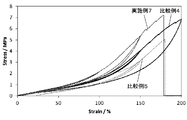
- FIG. 3 is a diagram showing stress-strain curves obtained by tensile tests of Examples 1 to 3 and Comparative Example 1. It is a figure which shows the stress-strain curve obtained by the tension test of Example 3, 5, 6 and the comparative examples 1 and 2.
- A) is a figure which shows the breaking stress when content of the polyurethane in polystyrene is changed.
- (B) is a figure which shows the fracture
- Example 8 It is a figure which shows the disperse
- (c) is a figure which shows the PMMA / PDMS composite film (Example 9) which disperse
- (D) is a figure which shows a PDMS film. It is a figure which shows the result of having observed the film obtained in Example 7 and the comparative example 5 with SEM (scanning electron microscope).
- (A) is a film obtained by continuously dropping polyvinyl alcohol while applying voltage to the PDMS film (Comparative Example 5), and (b) is a PVA / PDMS composite film in which PVA is dispersed in PDMS ( (Example 7) It is a figure which shows. 6 is a diagram showing stress-strain curves obtained by tensile tests of Examples 8 and 9 and Comparative Example 4. FIG. It is a figure which shows the stress-strain curve obtained by the tension test of Example 7 and Comparative Examples 4 and 5.
- FIG. 1 is a diagram for explaining the manufacturing method of the present embodiment.
- a voltage is applied between the melt, solution or dispersion 1 of the first polymer as the base material and the melt, solution or dispersion 2 of the second polymer as the dispersion material.
- the melt, solution or dispersion 2 of the second polymer is charged into the melt, solution or dispersion 1 of the first polymer to obtain the composite 4 in which the second polymer is dispersed in the first polymer. is there.
- the melt, solution or dispersion 1 of the first polymer is dropped by dropping the melt, solution or dispersion 2 of the second polymer into the melt, solution or dispersion 1 of the first polymer. It is preferable to add the melt, solution or dispersion 2 of the second polymer to The dripping 3 may be jetted using gas.
- the manufacturing apparatus used in the method of the present embodiment includes a needle 5 connected to one pole of a voltage source (not shown), a melt of a second polymer, A syringe 6 for containing the solution or dispersion 2, a syringe pump 7 for extruding the melt of the second polymer, the solution 2 or the dispersion 2, and the melt, solution 1 or dispersion 1 of the first polymer are added, and a composite production field A collector 8 and a plate-like electrode 9 provided on the bottom surface of the collector 8 and charged to the opposite polarity to the needle 5 by being connected to the other pole of a voltage source (not shown). Have.
- a general polymer compound can be used, and it may be a natural polymer compound or a synthetic polymer compound. Further, it may be a thermosetting resin or a thermoplastic resin. Examples of natural synthetic compounds include cellulose, lignin, chitin, chitosan, protein, collagen, deoxyribonucleic acid, ribonucleic acid and the like.
- thermoplastic resin examples include polypropylene, polycarbonate, polyamide, polyethylene, polyvinyl chloride, polyvinylidene chloride, polyethylene terephthalate, polybutylene terephthalate, polystyrene, ABS resin (acrylonitrile-butadiene-styrene copolymer resin), AS resin (acrylonitrile).
- polystyrene copolymer resin polymethyl methacrylate, polyacetal, polyphenylene sulfide, polyphenylene ether, polyether ether ketone, polysulfone, polyethersulfone, polyamideimide, polyetherimide, thermoplastic polyimide, natural rubber, polyisoprene, chloroprene rubber , Polystyrene, nitrile rubber, ethylene-propylene rubber, polybutadiene, styrene-butadiene rubber Butyl rubber, epichlorohydrin rubber, acrylic rubber, can be used polyurethane, fluororubber, and silicone rubber.
- thermosetting resin a resin that can maintain a molten state or a solution state before the start of curing is preferably used.
- an epoxy resin a phenol resin, or the like can be used.
- Others polyethylene glycol, polypropylene glycol, polyvinyl alcohol, polyamide, polyester, polyacetal, polycarbonate, polystyrene, acrylonitrile-styrene copolymer, styrene-butadiene copolymer, ethylene-propylene rubber, ethylene-butylene rubber, polynorbornene, acrylonitrile Butadiene copolymer, polysiloxane (eg, polydimethylsiloxane, polydiethylsiloxane, polyethylmethylsiloxane, polymethylphenylsiloxane), polysilane (eg, polymethylphenylsilane, polydiphenylsilane, polybiphenylsilane, polyal
- a general polymer compound can also be used, and it may be a natural polymer compound or a synthetic polymer compound. Further, it may be a thermosetting resin or a thermoplastic resin. Specifically, polymers used as the first polymer exemplified above can be widely used. Two or more of these may be used in combination, but at least one of the polymers different from the first polymer is used.
- the solvent or dispersion medium used in the solution or dispersion of the first polymer may be any solvent or dispersion medium that can dissolve or disperse the first polymer.
- a solvent in which the solubility of the second polymer is relatively low as compared with the solubility of the first polymer is more preferable.
- the content of the first polymer is preferably 0.01% by weight or more and preferably 0.1% by weight or more with respect to the entire solution or dispersion of the first polymer. There is no particular upper limit, and it can be 100% by weight or less. Alternatively, the first polymer heated and melted may be used.
- the first polymer only needs to have fluidity in the collector 8, and the liquid first polymer can be used as it is as a melt of the first polymer under the temperature conditions at the time of manufacture. By doing so, a melt of the first polymer may be prepared.
- the first polymer solution the first polymer need not be completely dissolved.
- a part of the first polymer may be dispersed, emulsified, or gelled.
- an additive such as a salt or a surfactant may be added.
- the melt, solution or dispersion 1 of the first polymer may be stirred.
- the solvent or dispersion medium used for the solution or dispersion of the second polymer is only required to dissolve the second polymer, and preferably has volatility.
- the first polymer is exemplified.
- One type or two or more types can be used.
- the solvent or dispersion medium used for the solution or dispersion of the second polymer may be the same as or different from the solvent or dispersion medium used for the solution or dispersion of the first polymer.
- the second polymer only needs to have fluidity that can be extruded from the needle 5 shown in FIG. 1, and the second polymer does not need to be completely dissolved in the solution of the second polymer.
- the second polymer that is liquid under the temperature conditions during production can be used as the melt of the second polymer as it is, and the melt of the first polymer may be prepared by heating the needle 5 or syringe 6. Further, a part of the second polymer may be dispersed, emulsified, or gelled. In order to make the second polymer into solution, dispersion, emulsification or gelation, an additive such as a salt or a surfactant may be added.
- the content of the second polymer is preferably 0.01% by weight or more, and more preferably 0.1% by weight or more with respect to the entire solution or dispersion of the second polymer. More preferably. There is no particular upper limit, and it can be 100% by weight or less. Alternatively, the second polymer heated and melted may be used.
- An electric field of 0.1 to 2 kV / cm, in particular 0.5 to 1 kV / cm, between the melt, solution or dispersion 1 of the first polymer and the melt, solution or dispersion 2 of the second polymer It is preferable to adjust the distance between the needle 5 and the electrode 9 and the applied voltage so as to be formed.
- the inner diameter of the needle 5 is 0.05 to 1 mm, a second polymer having a micro-order or nano-order diameter can be dispersed in the first polymer.
- the second polymer is preferably added in an amount of 0.01 to 99% by weight, more preferably 0.05 to 50% by weight, even more preferably 0.1 to 20% by weight based on the weight of the first polymer. .
- the charging rate of the second polymer to the first polymer can be set as appropriate, but it is preferable to add 0.01 to 1 times the amount per hour with respect to the weight of the first polymer. It is more preferable to add up to 0.5 times the amount.
- the dropping time is 5 minutes or more. Is preferable, and 30 minutes or more is more preferable. There is no particular upper limit, and for example, it can be dropped over 120 minutes.
- the melt, solution or dispersion 2 of the second polymer may be continuously dropped or sprayed on the melt, solution or dispersion 1 of the first polymer, or may be dropped or sprayed discontinuously.
- the second polymer is incorporated into the first polymer in a thread form, and as shown in FIG. 2A, a composite in which the fibrous second polymer is dispersed in the first polymer can be obtained.
- the melt, solution or dispersion 2 of the second polymer is dropped or jetted discontinuously, the second polymer is taken into the first polymer as droplets, as shown in FIG. A composite in which a particulate (bead-like) second polymer is dispersed in the first polymer can be obtained.
- the diameter and length of the dispersion material can be appropriately designed depending on the application, but the fiber diameter of the dispersion material is 1 ⁇ 10.
- the thickness may be 1 to 5 ⁇ 10 5 nm, preferably 5 ⁇ 10 1 to 2 ⁇ 10 4 nm, and more preferably 1 ⁇ 10 2 to 1 ⁇ 10 3 nm.
- the fiber length of the dispersion material can be several ⁇ m to several m, preferably 1 ⁇ 10 ⁇ 3 to 1 ⁇ 10 2 cm, and more preferably 1 ⁇ 10 ⁇ 1 to 5 ⁇ .
- the range can be 10 1 cm.
- the fiber diameter of the dispersion material can be observed using an SEM (scanning electron microscope).
- the fiber length of the dispersion material can be observed using an SEM (scanning electron microscope), but may be observed visually.
- the average particle diameter of the dispersion material can be several tens nm to several hundreds ⁇ m, and preferably 10 nm to 50 ⁇ m. More preferably, the thickness can be 50 nm to 2 ⁇ m, and still more preferably 100 nm to 1 ⁇ m.
- the average particle diameter of the particulate dispersion material can also be observed using a SEM (scanning electron microscope).
- the composite obtained in this way can be processed into a desired shape.
- various injection molding materials, extrusion molding materials, film molding materials, press molding materials, blow molding materials and the like can be used widely.
- a film having a thickness of 1 to 100 ⁇ m can be obtained.
- the used solvent and dispersion medium may be removed by drying before processing and molding.
- the drying is not particularly limited as long as the solvent / dispersion medium can be volatilized.
- the drying can be performed by heating under atmospheric pressure or reduced pressure.
- the temperature for drying by heating can be set to be equal to or higher than the boiling point of the solvent or the dispersion medium (the azeotropic temperature when the mixed solvent or the mixed dispersion medium is used).
- a mixture of a prepolymer (main agent) of the first and second polymers and a curing agent may be used as the melt, solution or dispersion 1, a mixture of the first polymer prepolymer (main agent) and the curing agent is used as the first polymer melt, solution or dispersion 1, the first polymer melt, solution or dispersion containing the main agent and the curing agent is used.
- a state where a voltage is applied to the liquid 1 a melt, solution or dispersion 2 of the second polymer is added, and then the prepolymer (main agent) and the curing agent are cured to form the first polymer.
- the curing reaction may be performed simultaneously with the drying step, or may be performed before or after the drying step.
- the second polymer melt, solution or dispersion 2 containing a mixture of a prepolymer (main agent) of the second polymer and a curing agent is used.
- Such an aspect can be taken, for example, when polysiloxane, polyurethane, epoxy resin or the like is used as the first polymer or the second polymer. What is necessary is just to select what is normally used in order to form the target 1st polymer and 2nd polymer, and the kind of prepolymer and a hardening
- the second polymer is added to the melt, solution or dispersion 1 of the first polymer in a state where a voltage is applied between the first polymer serving as the base material and the second polymer serving as the dispersion material.
- the melt, solution or dispersion 2 is added.
- Example 1 Using the configuration shown in FIG. 1, the composite shown in FIG. Polystyrene (product number: 430102, manufactured by Aldrich, number average molecular weight 140,000, Tg 94 ° C.) is used as the first polymer, which is dissolved in 1,2-dichlorobenzene and contains 5% by weight of the first polymer. A solution of the first polymer was prepared. Polyurethane (Peresen 2363-55DE, manufactured by Dow Chemical Japan Co., Ltd.) was used as the second polymer, and this was dissolved in a mixed solvent of tetrahydrafuran / dimethylformamide (blending ratio 50/50). A second polymer solution containing% was prepared.
- Polystyrene product number: 430102, manufactured by Aldrich, number average molecular weight 140,000, Tg 94 ° C.
- Polyurethane Peresen 2363-55DE, manufactured by Dow Chemical Japan Co., Ltd.
- Example 2 The solution of the second polymer was dripped continuously into the solution of the first polymer for 15 minutes by the method of Example 1 so that the second polymer contained 1.2% by weight with respect to the whole first polymer.
- Example 1 was repeated except that the second polymer solution was added to the polymer solution.
- Example 3 The solution of the second polymer was dripped continuously into the solution of the first polymer for 30 minutes by the method of Example 1 so that the second polymer contained 3.6% by weight with respect to the entire first polymer.
- Example 5 The solution of the second polymer was continuously dropped into the solution of the first polymer for 60 minutes by the method of Example 1 so that the second polymer contained 7.0% by weight with respect to the entire first polymer.
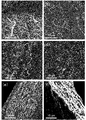
- FIG. 4 shows the results obtained by observing the films obtained in Examples 1 to 5 and Comparative Example 1 at a magnification of 5,000 with an SEM.
- 4A is a diagram showing the film of Comparative Example 1
- FIG. 4B is a diagram showing the film of Example 1
- FIG. 4C is a diagram showing the film of Example 2.
- 4 (d) is a diagram showing the film of Example 3
- FIG. 4 (e) is a diagram showing the film of Example 4
- FIG. 4 (f) is a diagram showing the film of Example 5. It is.
- FIG. 4 shows the result of magnifying and observing Example 3.
- 5A is an enlarged view of 5,000 times
- FIG. 5B is an enlarged view of 20,000 times
- FIG. 5C is an enlarged view of 50,000 times
- FIG. 5D is an enlarged view of 100,000 times.
- the fibrous dispersion material was uniformly dispersed without agglomeration.
- the circled portions in FIGS. 5 (b) and 5 (c) there is not much space between the dispersion material (polyurethane) and the base material (polystyrene), and there is also a state where it is stuck. From this, it was suggested that in the composite of the example, good interfacial adhesion was obtained between the base material and the dispersion material.
- Example 1 Fiber diameter 490 nm
- Example 2 Fiber diameter 540 nm
- Example 3 Fiber diameter 390 nm
- Example 4 Fiber diameter 480 nm
- Example 5 Fiber diameter 360 nm
- Example 6 Fiber diameter 650 nm In the films of Examples 1 to 6, the fiber length of the dispersion material was observed to be 6 to 9 cm with the naked eye.
- FIG. 6 shows stress-strain curves obtained by the tensile tests of Examples 1 to 3 and Comparative Example 1.
- FIG. 7 shows stress-strain curves obtained by the tensile tests of Examples 3, 5, and 6 and Comparative Examples 1 and 2.
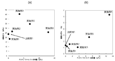
- FIG. 8A shows the result of calculating the breaking stress in each film from the stress-strain curves shown in FIGS.
- FIG. 8B shows the results of plotting the breaking strain in each film calculated from the stress-strain curves shown in FIGS.
- each Example and Comparative Example 1 were plotted with the content of the second polymer relative to the entire first polymer as the horizontal axis and the breaking stress or breaking strain as the vertical axis. From the result of FIG. 8, it was shown that the breaking stress and breaking strain increase by dispersing polyurethane fibers in polystyrene using the method of the present invention.
- Example 7 Using the configuration shown in FIG. 1, a composite shown in FIG. 2 (a) was prepared, which was composed of polydimethylsiloxane (PDMS) as the first polymer and polyvinyl alcohol as the second polymer.
- a melt of the first polymer was prepared by mixing the main agent (PDMS prepolymer) and the curing agent at a ratio of 10: 1 (weight ratio) using SILPOT 184 (manufactured by Toray Dow Corning). Further, polyvinyl alcohol (polyvinyl alcohol 1500, manufactured by JUNSEI) was dissolved in pure water to prepare a second polymer solution containing 8% by weight of the second polymer.
- PDMS polydimethylsiloxane
- SILPOT 184 manufactured by Toray Dow Corning
- Example 8 Using the configuration shown in FIG. 1, a composite shown in FIG. 2A was prepared, which was made up of PDMS as the first polymer and polymethylphenylsiloxane as the second polymer. In the same manner as in Example 7, a melt of the first polymer was prepared. As the second polymer, polymethylphenylsiloxane (product name: Flake Resin, manufacturer: manufactured by Toray Dow Corning Co., Ltd.) was used. Prepared.
- Example 9 Using the configuration shown in FIG. 1, a composite shown in FIG. 2A was prepared, which was made up of PDMS as the first polymer and polymethyl methacrylate as the second polymer. In the same manner as in Example 7, a melt of the first polymer was prepared. Polymethylmethacrylate (product name: poly (methyl methacrylate, manufacturer: ALDRICH) was used as the second polymer, and this was dissolved in chloroform to prepare a solution of the second polymer containing 10% by weight of the second polymer.
- Polymethylmethacrylate product name: poly (methyl methacrylate, manufacturer: ALDRICH
- Example 4 The melt of the first polymer prepared in Example 1 was cured at 50 ° C. for 24 hours without dripping the solution of the second polymer to obtain a polydimethylsiloxane (PDMS) film.
- Example 5 The solution of the second polymer prepared in Example 7 was continuously dropped onto the electrode at a rate of 0.1 mL / h for 120 minutes to form a fiber membrane, and the fiber of the first polymer prepared in Example 7 was formed on this fiber membrane. The melt was poured and cured at 50 ° C. for 24 hours to produce a composite containing 1% by weight of the second polymer.
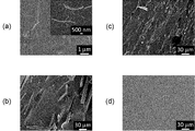
- FIG. 10 shows the results obtained by observing the films obtained in Examples 7 to 9 and Comparative Example 4 with an SEM enlarged.
- FIG. 10 (a) shows an enlarged view of 10,000 times the film of Example 7
- FIG. 10 (b) shows an enlarged view of 300 times of the film of Example 8
- FIG. 10 (c) shows Example 9.
- FIG. 10 (d) shows a 300 times enlarged view of the film of Comparative Example 4.
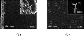
- FIG. 11A is a film cross section of Comparative Example 5, and FIG.
- Example 11B is a film cross section of Example 7.
- Comparative Example 5 only the polyvinyl ether film was formed on the surface of the polydimethylsiloxane film onto which the second polymer solution was continuously dropped, and changes were observed inside the polydimethylsiloxane film.
- fibrous polyvinyl ether portion surrounded by ⁇ in FIG. 11B was dispersed inside the polydimethylsiloxane film.
- Example 7 Fiber diameter 300 nm
- Example 8 Fiber diameter 1.0 ⁇ 10 5 nm
- Example 9 Fiber diameter 2.0 ⁇ 10 5 nm In the films of Examples 7 to 9, it was observed that the fiber length of the dispersion material was 6 to 9 cm with the naked eye.
- Table 1 shows the Young's modulus obtained from the slopes (strain range of 0.1 to 0.5%) of the stress-strain curves shown in FIGS. 12 and 13 for Examples 7 to 9 and Comparative Example 4.
- polyvinyl alcohol (PVA) film product name: polyvinyl alcohol 1500, manufactured by JUNSEI
- polymethylpolysiloxane (PDMS) film product name: SILPOT184, manufacturer: Toray Dow Corning
- PMMA polymethyl methacrylate
- Table 1 shows the results of measuring the Young's modulus obtained by a tensile test in the same manner for the product name poly (methyl methacrylate) (manufactured by ALDRICH, Inc.) (both having a thickness of 0.1 to 0.2 ⁇ m). Show.
- the composite films of Examples 7 to 9 all showed different mechanical properties from the film made of the first polymer and the film made of the second polymer.
Landscapes
- Chemical & Material Sciences (AREA)
- Health & Medical Sciences (AREA)
- Chemical Kinetics & Catalysis (AREA)
- Medicinal Chemistry (AREA)
- Polymers & Plastics (AREA)
- Organic Chemistry (AREA)
- Compositions Of Macromolecular Compounds (AREA)
- Processes Of Treating Macromolecular Substances (AREA)
Abstract
本発明は、母材となる第一ポリマーの溶融物、溶液又は分散液(1)と、分散材となる第二ポリマーの溶融物、溶液又は分散液(2)との間に電圧を印加した状態で、第一ポリマーの溶融物、溶液又は分散液(1)に第二ポリマーの溶融物、溶液又は分散液(2)を投入して、第一ポリマーに第二ポリマーが分散したコンポジット(4)を得るコンポジットの製造方法である。
Description
本発明は、コンポジットの製造方法及びそのコンポジットに関する。
近年、樹脂を母材として適当な分散材を分散させることで、各種樹脂に対し、新たな機能を付与し、樹脂の特性や性能の改善を図る試みがなされている。
ポリマー系ナノコンポジットの製造法としては、層間挿入法やモレキュラーコンポジット形成法等が知られている(非特許文献1)。
層間挿入法とは、無機層状物質の層剥離を行って1層ずつポリマー中に安定に分散させる方法である。この方法は、基本的には、層間挿入(Intercalation)の工程と層剥離(Exfoliation)工程に分けられるが、これをさらに改良した一段法も開発されている。
モレキュラーコンポジット形成法とは、ポリアミド(PA)やポリエチレンテレフタレート(PET)等の屈曲性ポリマー中に液晶性ポリマー(Liquid Crystal Polymer:LCP)等の剛直性ポリマーが分子次元又はミクロフィブリル次元で分散しているコンポジットを作製する方法である。もともとは、共通溶剤に溶解させた再沈により作製される方法であったが、1990年代になってごく少量のLCPとエンジニアプラスチックとを溶融混練することにより、性能の優れたコンポジットが作製されることが見出され、再び脚光を浴びている。この方法においては,相溶化剤として第三成分の混合が必要であり、分散相のサイズが0.5μm以上のコンポジットが得られるが、これをナノ次元化する技術が要望されている。
具体的なポリマー系コンポジットの製造例としては、例えば特許文献1のようなものがある。特許文献1には、母材となる溶融状態の熱可塑性樹脂に対し、天然又は合成の高分子化合物と溶媒とよりなる分散材液を投入し、これらに剪断力を加え,溶媒を除去することにより、母材と該母材に分散した分散材とよりなる樹脂組成物を作製する樹脂組成物の製造方法が記載されている。この方法によれば、分散材を母材に対し微細かつ均一に分散させることができるとされている。
また、ポリマー繊維を製造する方法としてエレクトロスピニング法が知られている(特許文献2、3)。
特許文献2には、ポリウレタン及び他の繊維生成用重合体の溶液を静電場に導入し、溶液の液滴を繊維状に細くし、繊維が捕集される電極の方向に延伸する静電紡糸法が記載されている。この方法によれば、溶媒を蒸発させて、静電場で繊維を調節させることで、電極上に0.1~25μm程度、好ましくは0.5~10μmの細い繊維を捕集できると記載されている。
特許文献3では、溶媒可溶なポリイミドを用いてエレクトロスピニング法によりナノファイバーを形成する際に、第4級アンモニウム塩などの塩を添加するあるいはポリイミドを溶解する溶媒の組み合わせにより、微細な径を有するとともに、得られるファイバーの径の均一性に優れたポリイミドナノファイバーが得られるとされている。
ポリマー系ナノコンポジットの技術動向、中條澄編集、2001年、シーエムシー出版、14-20頁
しかしながら、上記従来技術には、以下の課題を有していた。
層間挿入法において、完全に層剥離させることが理想だが、剥離しない部分が残るため、完全層剥離し均一分散したコンポジットを作製することは困難である。また、この方法では、二軸延伸機によりシートを作製するが、その時のせん断、圧縮のかけ方により分散状態が変化してしまう。特に配向性が出てきてしまい等方性均質材料を作製できなくなる懸念がある。
層間挿入法において、完全に層剥離させることが理想だが、剥離しない部分が残るため、完全層剥離し均一分散したコンポジットを作製することは困難である。また、この方法では、二軸延伸機によりシートを作製するが、その時のせん断、圧縮のかけ方により分散状態が変化してしまう。特に配向性が出てきてしまい等方性均質材料を作製できなくなる懸念がある。
また、モレキュラーコンポジット形成法によれば、溶液での混合法ではナノ次元のLCPフィブリル分散相が報告されているが、大量生産には適さない。一方、溶融混練法では大量生産には適しているが、未だナノ次元LCPフィブリル分散相の作製にはいたっていない。
また、上記特許文献1では、天然高分子化合物やポリビニルアルコールを分散材とする場合は、そのまま溶融状態の母材原料に投入して分散できる一方、例えば、ポリイミドを分散材とする場合は、前駆体としてポリアミノ酸を用い母材原料と混じり合った状態で反応させる手法が取られている。また、特許文献1では、いかなる分散材のときに分散材をそのまま投入でき、いかなる分散材のときには前駆体を用いる必要があるのかの製造指針が何ら教示されていない。したがって、特許文献1記載の技術は、実施例に開示された以外の材料に応用することが困難である。また、分散材として前駆体を用いる手法は、前駆体液の調製工程が必要であり、作業が煩雑である。さらに、特許文献1の方法ではせん断力を加えるため、前述のとおり、分散状態が変化してしまい、特に配向性が出てきてしまい等方性均質材料を作製できなくなる懸念もある。
また、特許文献2、3に示すエレクトロスピニング法を用い、二種以上のポリマー溶液を電極に向けて放出することで、コンポジットを得る試みも考えられる。しかしながら、ポリマーの組合せによっては、溶媒に均一に溶解させにくいこともあり、この場合、母材ポリマーと分散材ポリマーとを電極に対して均一に噴出させることが難しくなる。また、均一に噴出できた場合も、噴出中に溶媒が蒸発してしまうなどの理由により、電極上で凝集が起きてしまい、分散材ポリマーを均一に母材ポリマーに分散させることができないという問題もある。
本発明は上記事情に鑑みてなされたものであり、その目的とするところは、母材となるポリマーに分散材となるポリマーを均一分散させて所望のコンポジットが得られる簡易な手法を提供することにある。
本発明によれば、母材となる第一ポリマーの溶融物、溶液又は分散液と、分散材となる第二ポリマーの溶融物、溶液又は分散液との間に電圧を印加した状態で、前記第一ポリマーの溶融物、溶液又は分散液に前記第二ポリマーの溶融物、溶液又は分散液を投入して、前記第一ポリマーに前記第二ポリマーが分散したコンポジットを得る、コンポジットの製造方法が提供される。
また、本発明によれば、上記のコンポジットの製造方法により得られる、コンポジットが提供される。
この発明によれば、母材となる第一ポリマーと、分散材となる第二ポリマーとの間に電圧を印加した状態で、第一ポリマーの溶融物、溶液又は分散液に第二ポリマーの溶融物、溶液又は分散液を投入する。これにより、第一ポリマーと第二ポリマーとの間の親和性が電気的に向上するため、第一ポリマーの溶融物、溶液又は分散液に接触した第二ポリマーは、即座に第一ポリマーに取り込まれることになり、第二ポリマーの凝集を防ぎつつ第二ポリマーを第一ポリマーに均一に分散させることができる。また、噴射や滴下など、投入の手法を適宜変更することで、分散材の形状を粒子状にしたり繊維状にしたりすることができる。したがって、簡易な手法で所望のコンポジットを得ることが可能になる。
本発明によれば、簡易な手法で所望のコンポジットを得ることができる。
上述した目的、およびその他の目的、特徴および利点は、以下に述べる好適な実施の形態、およびそれに付随する以下の図面によってさらに明らかになる。
以下、本発明の実施の形態について、図面を用いて説明する。尚、すべての図面において、同様な構成要素には同様の符号を付し、適宜説明を省略する。
図1は、本実施の形態の製造方法を説明する図である。本実施の形態の製造方法は、母材となる第一ポリマーの溶融物、溶液又は分散液1と、分散材となる第二ポリマーの溶融物、溶液又は分散液2との間に電圧を印加した状態で、第一ポリマーの溶融物、溶液又は分散液1に第二ポリマーの溶融物、溶液又は分散液2を投入して、第一ポリマーに第二ポリマーが分散したコンポジット4を得るものである。本実施形態の方法では、第二ポリマーの溶融物、溶液又は分散液2を第一ポリマーの溶融物、溶液又は分散液1に滴下することにより、第一ポリマーの溶融物、溶液又は分散液1に第二ポリマーの溶融物、溶液又は分散液2を投入することが好ましい。滴下3は、ガスを用いて噴射するものであってもよい。
本実施の形態の方法で用いる製造装置は、具体的には、図1で示すように、電圧源(図示せず)の一方の極に接続されたニードル5と、第二ポリマーの溶融物、溶液又は分散液2を入れるシリンジ6と、第二ポリマーの溶融物、溶液又は分散液2を押し出すシリンジポンプ7と、第一ポリマーの溶融物、溶液又は分散液1を入れるとともに、コンポジットの生成場ともなるコレクタ8と、コレクタ8の底面に備えられ、電圧源(図示せず)の他方の極に接続されることによりニードル5とは逆極性に帯電される、平板状の電極9と、を有する。
第一ポリマーとしては、一般的な高分子化合物を用いることができ、天然高分子化合物であってもよいし、合成高分子化合物であってもよい。また、熱硬化性樹脂であってもよいし、熱可塑性樹脂であってもよい。
天然合成化合物としては、セルロース、リグニン、キチン、キトサン、タンパク質、コラーゲン、デオキシリボ核酸、リボ核酸等が挙げられる。
熱可塑性樹脂としては、例えば、ポリプロピレン、ポリカーボネート、ポリアミド、ポリエチレン、ポリ塩化ビニル、ポリ塩化ビニリデン、ポリエチレンテレフタレート、ポリブチレンテレフタレート、ポリスチレン、ABS樹脂(アクリロニトリル-ブタジエン-スチレン共重合樹脂)、AS樹脂(アクリロニトリル-スチレン共重合樹脂)、ポリメチルメタクリレート、ポリアセタール、ポリフェニレンスルフィド、ポリフェニレンエーテル、ポリエーテルエーテルケトン、ポリサルフォン、ポリエーテルサルフォン、ポリアミドイミド、ポリエーテルイミド、熱可塑性ポリイミド、天然ゴム、ポリイソプレン、クロロプレンゴム、ポリスチレン、ニトリルゴム、エチレン-プロピレンゴム、ポリブタジエン、スチレン-ブタジエンゴム、ブチルゴム、エピクロルヒドリンゴム、アクリルゴム、ポリウレタン、フッ素ゴム、シリコーンゴムなどを用いることができる。
熱硬化性樹脂としては、硬化の開始前に溶融状態又は溶液状態を保持できるものを用いるとよいが、たとえば、エポキシ樹脂、フェノール樹脂などを用いることができる。
その他、ポリエチレングリコール、ポリプロピレングリコール、ポリビニルアルコール、ポリアミド、ポリエステル、ポリアセタール、ポリカーボネート、ポリスチレン、アクリロニトリル-スチレン共重合体、スチレン-ブタジエン共重合体、エチレン-プロピレンラバー,エチレン-ブチレンラバー、ポリノルボルネン、アクリロニトリル-ブタジエン共重合体、ポリシロキサン(例えば、ポリジメチルシロキサン、ポリジエチルシロキサン、ポリエチルメチルシロキサン、ポリメチルフェニルシロキサン)、ポリシラン(例えば、ポリメチルフェニルシラン、ポリジフェニルシラン、ポリビフェニルシラン、ポリアルキルナフチルシラン)等も用いることができる。
これらを二種以上組み合わせて用いることもできる。
天然合成化合物としては、セルロース、リグニン、キチン、キトサン、タンパク質、コラーゲン、デオキシリボ核酸、リボ核酸等が挙げられる。
熱可塑性樹脂としては、例えば、ポリプロピレン、ポリカーボネート、ポリアミド、ポリエチレン、ポリ塩化ビニル、ポリ塩化ビニリデン、ポリエチレンテレフタレート、ポリブチレンテレフタレート、ポリスチレン、ABS樹脂(アクリロニトリル-ブタジエン-スチレン共重合樹脂)、AS樹脂(アクリロニトリル-スチレン共重合樹脂)、ポリメチルメタクリレート、ポリアセタール、ポリフェニレンスルフィド、ポリフェニレンエーテル、ポリエーテルエーテルケトン、ポリサルフォン、ポリエーテルサルフォン、ポリアミドイミド、ポリエーテルイミド、熱可塑性ポリイミド、天然ゴム、ポリイソプレン、クロロプレンゴム、ポリスチレン、ニトリルゴム、エチレン-プロピレンゴム、ポリブタジエン、スチレン-ブタジエンゴム、ブチルゴム、エピクロルヒドリンゴム、アクリルゴム、ポリウレタン、フッ素ゴム、シリコーンゴムなどを用いることができる。
熱硬化性樹脂としては、硬化の開始前に溶融状態又は溶液状態を保持できるものを用いるとよいが、たとえば、エポキシ樹脂、フェノール樹脂などを用いることができる。
その他、ポリエチレングリコール、ポリプロピレングリコール、ポリビニルアルコール、ポリアミド、ポリエステル、ポリアセタール、ポリカーボネート、ポリスチレン、アクリロニトリル-スチレン共重合体、スチレン-ブタジエン共重合体、エチレン-プロピレンラバー,エチレン-ブチレンラバー、ポリノルボルネン、アクリロニトリル-ブタジエン共重合体、ポリシロキサン(例えば、ポリジメチルシロキサン、ポリジエチルシロキサン、ポリエチルメチルシロキサン、ポリメチルフェニルシロキサン)、ポリシラン(例えば、ポリメチルフェニルシラン、ポリジフェニルシラン、ポリビフェニルシラン、ポリアルキルナフチルシラン)等も用いることができる。
これらを二種以上組み合わせて用いることもできる。
第二ポリマーもまた、一般的な高分子化合物を用いることができ、天然高分子化合物であってもよいし、合成高分子化合物であってもよい。また、熱硬化性樹脂であってもよいし、熱可塑性樹脂であってもよい。
具体的には、上記例示した第一ポリマーとして用いられるポリマーを広く用いることができる。これらを二種以上組み合わせて用いることもできるが、少なくとも一種は、第一ポリマーと異なる種類のポリマーを用いる。
具体的には、上記例示した第一ポリマーとして用いられるポリマーを広く用いることができる。これらを二種以上組み合わせて用いることもできるが、少なくとも一種は、第一ポリマーと異なる種類のポリマーを用いる。
第一ポリマーの溶液又は分散液に用いられる溶媒又は分散媒は、第一ポリマーを溶解又は分散させられるものであればよいが、好ましくは、適度な揮発性を有するものがよく、コンポジットの生成場において、第一ポリマーの溶解性に比較して第二ポリマーの溶解性が相対的に低い溶媒がより好ましい。具体的には、水、メタノール、エタノール、プロパノール、イソプロパノール、ベンジルアルコール、フェノール、酢酸等のプロトン性極性溶媒、アセトン、テトラヒドロフラン、ピリジン、N,N-ジメチルアセトアミド、1、4-ジオキサン、N,N-ジメチルホルムアミド、ジメチルスルホキシド、N-メチルピロリドン、エチレンカーボネート、プロピレンカーボネート、ジメチルカーボネート、1,3-ジメチル-2-イミダゾリジノン、エチルメチルカーボネート、スルホラン等の非プロトン性極性溶媒、ジクロロメタン、クロロホルム、四塩化炭素、ヘキサン、シクロヘキサン、ジエチルエーテル、1,2-ジメトキシエタン、1,3-ジオキソラン、1,1,2-トリクロロエタン、ベンゼン、トルエン、キシレン、ジクロロベンゼン、酢酸エチル等の非極性溶媒が挙げられる。これらを二種以上組み合わせて用いてもよい。
溶液又は分散液中、第一ポリマーの含有量は、第一ポリマーの溶液又は分散液全体に対して、0.01重量%以上あることが好ましく、0.1重量%以上であることが好ましい。上限は特になく、100重量%以下とすることができる。また、第一ポリマーを加熱して、溶融させたものを用いてもよい。
第一ポリマーは、コレクタ8中で流動性を有していればよく、製造時の温度条件下で液状の第一ポリマーは、そのまま第一ポリマーの溶融物とすることができ、コレクタ8を加熱することで第一ポリマーの溶融物を調製してもよい。また、第一ポリマーの溶液においては、第一ポリマーが完全に溶解している必要はない。第一ポリマーの一部が分散していてもよいし、乳化されていてもよいし、ゲル化されていてもよい。第一ポリマーを溶液、分散、乳化又はゲル化させるため、塩や界面活性剤などの添加剤が加えられていてもよい。また、第一ポリマーを流動させるため、第一ポリマーの溶融物、溶液又は分散液1は、攪拌されてもよい。
第二ポリマーの溶液又は分散液に用いられる溶媒又は分散媒は、第二ポリマーを溶解させることができればよく、好ましくは、揮発性を有するものがよいが、具体的には、第一ポリマーで例示したものを一種又は二種以上用いることができる。第二ポリマーの溶液又は分散液に用いられる溶媒又は分散媒は、第一ポリマーの溶液又は分散液に用いられる溶媒又は分散媒と同じであってもよいし、異なっていてもよい。
第二ポリマーは、図1で示すニードル5から押し出しできる程度の流動性を有していればよく、第二ポリマーの溶液において、第二ポリマーが完全に溶解している必要はない。製造時の温度条件下で液状の第二ポリマーは、そのまま第二ポリマーの溶融物とすることができ、ニードル5やシリンジ6を加熱することで第一ポリマーの溶融物を調製してもよい。また、第二ポリマーの一部が分散していてもよいし、乳化されていてもよいし、ゲル化されていてもよい。第二ポリマーを溶液、分散、乳化又はゲル化させるため、塩や界面活性剤などの添加剤が加えられていてもよい。
第二ポリマーの溶液又は分散液中、第二ポリマーの含有量は、第二ポリマーの溶液又は分散液全体に対して、0.01重量%以上あることが好ましく、0.1重量%以上であることが更に好ましい。上限は特になく、100重量%以下とすることができる。また、第二ポリマーを加熱して、溶融させたものを用いてもよい。
第一ポリマーの溶融物、溶液又は分散液1と、第二ポリマーの溶融物、溶液又は分散液2との間には、0.1~2kV/cm、特に0.5~1kV/cmの電場が形成されるように、ニードル5と電極9との間隔、及び、印加される電圧を調節することが好ましい。ニードル5の内径は、0.05~1mmとすると、マイクロオーダーやナノオーダーの径を有する第二ポリマーを第一ポリマーに分散させることができる。
第二ポリマーは、第一ポリマーの重量に対して、0.01~99重量%添加することが好ましく、0.05~50重量%添加するとより好ましく、0.1~20重量%添加すると更に好ましい。第二ポリマーの第一ポリマーへの投入速度は、適宜設定することができるが、第一ポリマーの重量に対して、1時間あたり、0.01~1倍量投入することが好ましく、0.05~0.5倍量投入することがより好ましい。また、第二ポリマーの溶融物、溶液又は分散液2を第一ポリマーの溶融物、溶液又は分散液1に滴下する場合、時間をかけながら、滴下することが好ましく、滴下時間は、5分以上が好ましく、30分以上がより好ましい。上限は特になく、例えば、120分かけて滴下することもできる。
第二ポリマーの溶融物、溶液又は分散液2は、第一ポリマーの溶融物、溶液又は分散液1に連続的に滴下又は噴射してもよいし、不連続に滴下又は噴射してもよい。連続的に滴下することで、第二ポリマーが糸状に第一ポリマーに取り込まれ、図2(a)で示すように、繊維状の第二ポリマーが第一ポリマーに分散したコンポジットを得ることができる。一方、第二ポリマーの溶融物、溶液又は分散液2が、不連続に滴下又は噴射された場合は、第二ポリマーが液滴として第一ポリマーに取り込まれ、図2(b)で示すように、粒子状(ビーズ状)の第二ポリマーが第一ポリマーに分散したコンポジットを得ることができる。
図2(a)のような繊維状の分散材が分散したコンポジットの場合、用途によって分散材の直径及び長さを適宜設計して得ることができるが、分散材の繊維径は、1×101~5×10⁵nmとすることができ、好ましくは、5×101~2×10⁴nm、より好ましくは、1×10²~1×10³nmとすることができる。分散材の繊維長は、数μm~数mとすることができ、好ましくは、1×10⁻³~1×102cmとすることができ、より好ましくは、1×10⁻¹~5×101cmの範囲とすることができる。分散材の繊維径は、SEM(走査型電子顕微鏡)を用いて観察することができる。分散材の繊維長は、SEM(走査型電子顕微鏡)を用いて観察することができるが、目視で観察してもよい。
図2(b)のような粒子状の分散材が分散したコンポジットの場合、分散材の平均粒径は、数十nm~数百μmとすることができ、好ましくは、10nm~50μmとすることができ、より好ましくは、50nm~2μm、さらに好ましくは、100nm~1μmとすることができる。粒子状の分散材の平均粒径もまた、SEM(走査型電子顕微鏡)を用いて観察することができる。
このようにして得られたコンポジットは、所望の形状に加工することができる。例えば、各種射出成型材料、押出成形材料、フィルム成形材料、プレス成形材料、ブロー成型材料等、幅広く用いることができる。これにより、例えば、厚み1~100μmのフィルムを得ることができる。
第一ポリマー及び第二ポリマーの少なくとも一方を溶液又は分散液として、第一ポリマーに第二ポリマーを投入したときは、加工成形する前に乾燥させて、使用した溶媒や分散媒を除去することが好ましい。乾燥は、溶媒・分散媒を揮発させることができればよく、例えば、大気圧又は減圧下で加熱により乾燥させることができる。加熱乾燥するときの温度は、溶媒又は分散媒の沸点以上(混合溶媒又は混合分散媒を用いたときは共沸温度)とすることができる。
なお、第一、第二ポリマーの溶融物、溶液又は分散液としては、第一、第二ポリマーのプレポリマー(主剤)と硬化剤との混合物を用いてもよい。第一ポリマーの溶融物、溶液又は分散液1として、第一ポリマーのプレポリマー(主剤)と硬化剤との混合物を用いる場合、主剤と硬化剤とを含む第一ポリマーの溶融物、溶液又は分散液1に電圧を印加した状態で、第二ポリマーの溶融物、溶液又は分散液2を投入した後に、プレポリマー(主剤)と硬化剤とを硬化させて第一ポリマーを形成させる工程を行う。硬化反応は、乾燥工程と同時に行ってもよいし、乾燥工程の前後に行ってもよい。また、第二ポリマーの溶融物、溶液又は分散液2として、第二ポリマーのプレポリマー(主剤)と硬化剤との混合物を含むものを用いた場合も同様にすることができる。こうした態様は、例えば、第一ポリマーや第二ポリマーとして、ポリシロキサン、ポリウレタン、エポキシ樹脂等を用いる場合にとることができる。プレポリマー及び硬化剤の種類や、配合比は、目的の第一ポリマーや第二ポリマーを形成させるため通常用いられるものを選択すればよい。
上述した方法によれば、母材となる第一ポリマーと、分散材となる第二ポリマーとの間に電圧を印加した状態で、第一ポリマーの溶融物、溶液又は分散液1に第二ポリマーの溶融物、溶液又は分散液2を投入する。これにより、第一ポリマーと第二ポリマーとの間の親和性が電気的に向上するため、第一ポリマーの溶融物、溶液又は分散液1に滴下3された第二ポリマーは、即座に第一ポリマーに取り込まれることになり、第二ポリマーの凝集を防ぎつつ第二ポリマーを第一ポリマーに均一に分散させることができる。また、噴射や滴下など、第二ポリマーの投入の方法を適宜変更することで、分散材の形状を粒子状にしたり繊維状にしたりすることができる。したがって、簡易な手法で所望のコンポジットを得ることが可能になる。
以上、図面を参照して本発明の実施形態について述べたが、これらは本発明の例示であり、上記以外の様々な構成を採用することもできる。
例えば、実施の形態では、第二ポリマーの溶融物、溶液又は分散液2を第一ポリマーの溶融物、溶液又は分散液1に投入する例を挙げて説明したが、第一ポリマーの溶融物、溶液又は分散液1に、第二ポリマーの溶融物、溶液又は分散液2を投入すると同時に、第二ポリマーの溶融物、溶液又は分散液2と同様に用意された同種又は異種のポリマーの溶融物、溶液又は分散液を一種又は複数種投入してもよい。この場合、第二ポリマーの溶融物、溶液又は分散液2と同様に用意された同種又は異種のポリマーの溶融物、溶液又は分散液もまた、滴下又は噴射により第一ポリマーの溶融物、溶液又は分散液1に投入することができる。
例えば、実施の形態では、第二ポリマーの溶融物、溶液又は分散液2を第一ポリマーの溶融物、溶液又は分散液1に投入する例を挙げて説明したが、第一ポリマーの溶融物、溶液又は分散液1に、第二ポリマーの溶融物、溶液又は分散液2を投入すると同時に、第二ポリマーの溶融物、溶液又は分散液2と同様に用意された同種又は異種のポリマーの溶融物、溶液又は分散液を一種又は複数種投入してもよい。この場合、第二ポリマーの溶融物、溶液又は分散液2と同様に用意された同種又は異種のポリマーの溶融物、溶液又は分散液もまた、滴下又は噴射により第一ポリマーの溶融物、溶液又は分散液1に投入することができる。
(実施例1)
図1で示す構成を用いて、図2(a)で示すコンポジットを作製した。
第一ポリマーとして、ポリスチレン(製品番号:430102、アルドリッチ社製、数平均分子量14万、Tg94℃)を用い、これを1,2-ジクロロベンゼンに溶解して、第一ポリマーを5重量%含有する第一ポリマーの溶液を調製した。
第二ポリマーとして、ポリウレタン(ペレセン2363-55DE、ダウケミカル日本社製)を用い、これをテトラヒドラフラン/ジメチルホルムアミドの混合溶媒(配合比率50/50)に溶解して、第二ポリマーを4重量%含有する第二ポリマーの溶液を調製した。
内径0.57μm、外径0.80mmのニードルを用い、気温22~27℃、湿度40~50%RH、ニードルと電極との間の距離は、8cmとし、7.2kVの電圧を印加しながら、上記調製した第二ポリマーの溶液を0.3mL/hの速度で第一ポリマーの溶液(2mL)に5分間連続して滴下し、第一ポリマー全体に対して、第二ポリマーが0.4重量%含有するように、第一ポリマーの溶液に第二ポリマーの溶液を投入した。その後、24時間100℃で乾燥して、フィルム状のコンポジットを得た。得られたコンポジットフィルムの厚みをSEMで計測したところ、51μm(N=1)であった。
図1で示す構成を用いて、図2(a)で示すコンポジットを作製した。
第一ポリマーとして、ポリスチレン(製品番号:430102、アルドリッチ社製、数平均分子量14万、Tg94℃)を用い、これを1,2-ジクロロベンゼンに溶解して、第一ポリマーを5重量%含有する第一ポリマーの溶液を調製した。
第二ポリマーとして、ポリウレタン(ペレセン2363-55DE、ダウケミカル日本社製)を用い、これをテトラヒドラフラン/ジメチルホルムアミドの混合溶媒(配合比率50/50)に溶解して、第二ポリマーを4重量%含有する第二ポリマーの溶液を調製した。
内径0.57μm、外径0.80mmのニードルを用い、気温22~27℃、湿度40~50%RH、ニードルと電極との間の距離は、8cmとし、7.2kVの電圧を印加しながら、上記調製した第二ポリマーの溶液を0.3mL/hの速度で第一ポリマーの溶液(2mL)に5分間連続して滴下し、第一ポリマー全体に対して、第二ポリマーが0.4重量%含有するように、第一ポリマーの溶液に第二ポリマーの溶液を投入した。その後、24時間100℃で乾燥して、フィルム状のコンポジットを得た。得られたコンポジットフィルムの厚みをSEMで計測したところ、51μm(N=1)であった。
(実施例2)
実施例1の方法で第二ポリマーの溶液を第一ポリマーの溶液に15分間連続して滴下し、第一ポリマー全体に対して、第二ポリマーが1.2重量%含有するように、第一ポリマーの溶液に第二ポリマーの溶液を投入した以外は、実施例1と同様にした。得られたコンポジットフィルムの厚みをSEMで計測したところ、58μm(平均値、N=3)であった。
実施例1の方法で第二ポリマーの溶液を第一ポリマーの溶液に15分間連続して滴下し、第一ポリマー全体に対して、第二ポリマーが1.2重量%含有するように、第一ポリマーの溶液に第二ポリマーの溶液を投入した以外は、実施例1と同様にした。得られたコンポジットフィルムの厚みをSEMで計測したところ、58μm(平均値、N=3)であった。
(実施例3)
実施例1の方法で第二ポリマーの溶液を第一ポリマーの溶液に30分間連続して滴下し、第一ポリマー全体に対して、第二ポリマーが3.6重量%含有するように、第一ポリマーの溶液に第二ポリマーの溶液を投入した以外は、実施例1と同様にした。得られたコンポジットフィルムの厚みをSEMで計測したところ、39μm(平均値、N=2)であった。
実施例1の方法で第二ポリマーの溶液を第一ポリマーの溶液に30分間連続して滴下し、第一ポリマー全体に対して、第二ポリマーが3.6重量%含有するように、第一ポリマーの溶液に第二ポリマーの溶液を投入した以外は、実施例1と同様にした。得られたコンポジットフィルムの厚みをSEMで計測したところ、39μm(平均値、N=2)であった。
(実施例4)
実施例1の方法で第二ポリマーの溶液を第一ポリマーの溶液に45分間連続して滴下し、第一ポリマー全体に対して、第二ポリマーが5.2重量%含有するように、第一ポリマーの溶液に第二ポリマーの溶液を投入した以外は、実施例1と同様にした。得られたコンポジットフィルムの厚みをSEMで計測したところ、40μm(平均値、N=3)であった。
実施例1の方法で第二ポリマーの溶液を第一ポリマーの溶液に45分間連続して滴下し、第一ポリマー全体に対して、第二ポリマーが5.2重量%含有するように、第一ポリマーの溶液に第二ポリマーの溶液を投入した以外は、実施例1と同様にした。得られたコンポジットフィルムの厚みをSEMで計測したところ、40μm(平均値、N=3)であった。
(実施例5)
実施例1の方法で第二ポリマーの溶液を第一ポリマーの溶液に60分間連続して滴下し、第一ポリマー全体に対して、第二ポリマーが7.0重量%含有するように、第一ポリマーの溶液に第二ポリマーの溶液を投入した以外は、実施例1と同様にした。得られたコンポジットフィルムの厚みをSEMで計測したところ、27μm(平均値、N=4)であった。
実施例1の方法で第二ポリマーの溶液を第一ポリマーの溶液に60分間連続して滴下し、第一ポリマー全体に対して、第二ポリマーが7.0重量%含有するように、第一ポリマーの溶液に第二ポリマーの溶液を投入した以外は、実施例1と同様にした。得られたコンポジットフィルムの厚みをSEMで計測したところ、27μm(平均値、N=4)であった。
(実施例6)
実施例1の方法で第二ポリマーの溶液を第一ポリマーの溶液に120分間連続して滴下し、第一ポリマー全体に対して、第二ポリマーが13重量%含有するように、第一ポリマーの溶液に第二ポリマーの溶液を投入した以外は、実施例1と同様にした。得られたコンポジットフィルムの厚みをSEMで計測したところ、25μm(平均値、N=3)であった。
実施例1の方法で第二ポリマーの溶液を第一ポリマーの溶液に120分間連続して滴下し、第一ポリマー全体に対して、第二ポリマーが13重量%含有するように、第一ポリマーの溶液に第二ポリマーの溶液を投入した以外は、実施例1と同様にした。得られたコンポジットフィルムの厚みをSEMで計測したところ、25μm(平均値、N=3)であった。
(比較例1)
実施例1で調製した第一ポリマーの溶液を、第二ポリマーの溶液を滴下せずに、24時間100℃で乾燥させて、ポリスチレンのフィルムを得た。得られたポリスチレンフィルムの厚みをSEMで計測したところ、85μm(N=1)であった。
実施例1で調製した第一ポリマーの溶液を、第二ポリマーの溶液を滴下せずに、24時間100℃で乾燥させて、ポリスチレンのフィルムを得た。得られたポリスチレンフィルムの厚みをSEMで計測したところ、85μm(N=1)であった。
(比較例2)
実施例1で調製した第二ポリマーの溶液を0.3mL/hの速度で電極に5分間連続して直接滴下し、24時間55℃で乾燥して、ポリウレタンフィルムを得た。得られたポリウレタンフィルムの厚みをSEMで計測したところ、15μm(平均値、N=4)であった。
実施例1で調製した第二ポリマーの溶液を0.3mL/hの速度で電極に5分間連続して直接滴下し、24時間55℃で乾燥して、ポリウレタンフィルムを得た。得られたポリウレタンフィルムの厚みをSEMで計測したところ、15μm(平均値、N=4)であった。
(比較例3)
実施例1で調製した第二ポリマーの溶液を0.3mL/hの速度で電極に60分間連続して直接滴下し、24時間55℃で乾燥して、ポリウレタンフィルムを得た。得られたポリウレタンフィルムの厚みをSEMで計測したところ、15μm(平均値、N=4)であった。
実施例1で調製した第二ポリマーの溶液を0.3mL/hの速度で電極に60分間連続して直接滴下し、24時間55℃で乾燥して、ポリウレタンフィルムを得た。得られたポリウレタンフィルムの厚みをSEMで計測したところ、15μm(平均値、N=4)であった。
<評価1>
1.分散性評価
実施例1~6、比較例1~3のフィルムを文字が印刷された紙上に置き、分散材の分散性の評価を行った。結果を図3に示す。図3(a)で示すように、比較例1のポリスチレンフィルムでは、フィルムを介して文字を明確に認識することができるが、比較例2のポリウレタンフィルムでは、フィルムを介して文字が認識できる一方濁っており、比較例3のポリウレタンフィルムでは、フィルムを介して文字を認識することができない。このように、純粋なポリスチレンフィルムは透明であるが、純粋なポリウレタンフィルムは濁っているため、ポリウレタンがポリスチレンフィルム中で凝集すると、フィルムに濁りが生じる。したがって、フィルムを通して文字が肉眼で認識できる程度(透明性評価)を確認することによって、分散材の凝集が生じているか否かを評価することができる。そこで、実施例1~6のフィルムについて、この透明性評価を行ったところ、図3(b)で示すように、実施例1~6のフィルムでは文字が明確に認識された。したがって、実施例1~6のフィルムでは、分散材のポリウレタンが凝集せずに均一にポリスチレンの母材に分散していることが示された。
1.分散性評価
実施例1~6、比較例1~3のフィルムを文字が印刷された紙上に置き、分散材の分散性の評価を行った。結果を図3に示す。図3(a)で示すように、比較例1のポリスチレンフィルムでは、フィルムを介して文字を明確に認識することができるが、比較例2のポリウレタンフィルムでは、フィルムを介して文字が認識できる一方濁っており、比較例3のポリウレタンフィルムでは、フィルムを介して文字を認識することができない。このように、純粋なポリスチレンフィルムは透明であるが、純粋なポリウレタンフィルムは濁っているため、ポリウレタンがポリスチレンフィルム中で凝集すると、フィルムに濁りが生じる。したがって、フィルムを通して文字が肉眼で認識できる程度(透明性評価)を確認することによって、分散材の凝集が生じているか否かを評価することができる。そこで、実施例1~6のフィルムについて、この透明性評価を行ったところ、図3(b)で示すように、実施例1~6のフィルムでは文字が明確に認識された。したがって、実施例1~6のフィルムでは、分散材のポリウレタンが凝集せずに均一にポリスチレンの母材に分散していることが示された。
2.SEMによる破面観察(1)
実施例1~5、比較例1で得られたフィルムをSEMで5千倍に拡大して観察した結果を図4に示す。図4(a)は、比較例1のフィルムを示す図であり、図4(b)が実施例1のフィルムを示す図であり、図4(c)が実施例2のフィルムを示す図であり、図4(d)が実施例3のフィルムを示す図であり、図4(e)が実施例4のフィルムを示す図であり、図4(f)が実施例5のフィルムを示す図である。図4で示すように、実施例1~5では、繊維状の分散材が確認された。
実施例3については拡大して観察した結果を図5に示す。図5(a)が5千倍、図5(b)が2万倍、図5(c)が5万倍、図5(d)が10万倍に拡大した図である。図示するように、繊維状の分散材が凝集せずに単一均等に分散していることが示された。また、図5(b)、(c)で丸く囲んだ部分で示すように、分散材(ポリウレタン)と母材(ポリスチレン)との間に空隙などはあまり見られずへばりついたような状態も見られたことから、実施例のコンポジットでは、母材と分散材との間に良好な界面接着が得られることが示唆された。
なお、SEMによる観察結果から、分散材の繊維径は以下のとおりであった(n=10)。
実施例1:繊維径490nm
実施例2:繊維径540nm
実施例3:繊維径390nm
実施例4:繊維径480nm
実施例5:繊維径360nm
実施例6:繊維径650nm
なお、実施例1~6のフィルムにおいて、分散材の繊維長は、肉眼で6~9cmであることが観察された。
実施例1~5、比較例1で得られたフィルムをSEMで5千倍に拡大して観察した結果を図4に示す。図4(a)は、比較例1のフィルムを示す図であり、図4(b)が実施例1のフィルムを示す図であり、図4(c)が実施例2のフィルムを示す図であり、図4(d)が実施例3のフィルムを示す図であり、図4(e)が実施例4のフィルムを示す図であり、図4(f)が実施例5のフィルムを示す図である。図4で示すように、実施例1~5では、繊維状の分散材が確認された。
実施例3については拡大して観察した結果を図5に示す。図5(a)が5千倍、図5(b)が2万倍、図5(c)が5万倍、図5(d)が10万倍に拡大した図である。図示するように、繊維状の分散材が凝集せずに単一均等に分散していることが示された。また、図5(b)、(c)で丸く囲んだ部分で示すように、分散材(ポリウレタン)と母材(ポリスチレン)との間に空隙などはあまり見られずへばりついたような状態も見られたことから、実施例のコンポジットでは、母材と分散材との間に良好な界面接着が得られることが示唆された。
なお、SEMによる観察結果から、分散材の繊維径は以下のとおりであった(n=10)。
実施例1:繊維径490nm
実施例2:繊維径540nm
実施例3:繊維径390nm
実施例4:繊維径480nm
実施例5:繊維径360nm
実施例6:繊維径650nm
なお、実施例1~6のフィルムにおいて、分散材の繊維長は、肉眼で6~9cmであることが観察された。
3.引張試験
引張試験機(TAインスツルメント社製、RSAIII)を用いて実施例1~3、5、6及び比較例1、2のフィルムの引張試験を行った。引張試験は、常温(25℃)、試験速度10mm/分でJIS K-7113に準拠して測定した。すなわち、測定試料はJIS規格によって定められた16.5×3mmの面積のものをダンベルカッターでフィルムから作製した。測定サンプルは各5回ずつ測定を行い、それらの平均を用いて各値を算出した。破断ひずみの値は試料が破断したときのひずみで算出した。破断ひずみの値は試料が最大応力を与えられた時を破断として算出した。図6は、実施例1~3及び比較例1の引張試験により得られた応力-ひずみ曲線を示す。図7は、実施例3、5、6及び比較例1、2の引張試験により得られた応力-ひずみ曲線を示す。また、図8(a)は、図6、7に示す応力-ひずみ曲線から各フィルムにおける破断応力を算出した結果を示す。図8(b)は、図6、7に示す応力-ひずみ曲線から各フィルムにおける破断ひずみを算出してプロットした結果を示す。図8では、第一ポリマー全体に対する第二ポリマーの含有量を横軸にし、破断応力又は破断ひずみを縦軸として、各実施例及び比較例1をプロットした。図8の結果から、本発明の方法を用いてポリスチレンにポリウレタンの繊維を分散させることにより、破断応力及び破断ひずみが増加することが示された。
引張試験機(TAインスツルメント社製、RSAIII)を用いて実施例1~3、5、6及び比較例1、2のフィルムの引張試験を行った。引張試験は、常温(25℃)、試験速度10mm/分でJIS K-7113に準拠して測定した。すなわち、測定試料はJIS規格によって定められた16.5×3mmの面積のものをダンベルカッターでフィルムから作製した。測定サンプルは各5回ずつ測定を行い、それらの平均を用いて各値を算出した。破断ひずみの値は試料が破断したときのひずみで算出した。破断ひずみの値は試料が最大応力を与えられた時を破断として算出した。図6は、実施例1~3及び比較例1の引張試験により得られた応力-ひずみ曲線を示す。図7は、実施例3、5、6及び比較例1、2の引張試験により得られた応力-ひずみ曲線を示す。また、図8(a)は、図6、7に示す応力-ひずみ曲線から各フィルムにおける破断応力を算出した結果を示す。図8(b)は、図6、7に示す応力-ひずみ曲線から各フィルムにおける破断ひずみを算出してプロットした結果を示す。図8では、第一ポリマー全体に対する第二ポリマーの含有量を横軸にし、破断応力又は破断ひずみを縦軸として、各実施例及び比較例1をプロットした。図8の結果から、本発明の方法を用いてポリスチレンにポリウレタンの繊維を分散させることにより、破断応力及び破断ひずみが増加することが示された。
4.熱物性評価
示差走査熱量計(DSC822e、Mettler社製)を用いて、実施例1、2、5、6、及び、比較例1、2の各フィルムの示差走査熱量測定を行った。50℃~200℃に昇温したときにおける熱流量の変化を図9に示す。各実施例のフィルムは、比較例1のポリスチレンフィルム、及び、比較例2のポリウレタンフィルムとは、異なる熱物性を示した。
示差走査熱量計(DSC822e、Mettler社製)を用いて、実施例1、2、5、6、及び、比較例1、2の各フィルムの示差走査熱量測定を行った。50℃~200℃に昇温したときにおける熱流量の変化を図9に示す。各実施例のフィルムは、比較例1のポリスチレンフィルム、及び、比較例2のポリウレタンフィルムとは、異なる熱物性を示した。
(実施例7)
図1で示す構成を用いて、第一ポリマーとしてポリジメチルシロキサン(PDMS)、第二ポリマーとしてポリビニルアルコールから構成される、図2(a)で示すコンポジットを作製した。SILPOT 184(東レ・ダウコーニング社製)を用い、主剤(PDMSプレポリマー)と硬化剤とを10:1(重量比)で混合することで、第一ポリマーの溶融物を調製した。また、ポリビニルアルコール(ポリビニルアルコール1500、JUNSEI社製)を純水に溶解して、第二ポリマーを8重量%含有する第二ポリマーの溶液を調製した。内径0.57μm、外径0.80mmのニードルを用い、気温22~27℃、湿度40~50%RH、ニードルと電極との間の距離は、8cmとし、7.2kVの電圧を印加しながら、上記調製した第二ポリマーの溶液を0.1mL/hの速度で第一ポリマーの溶融物(3.6~3.8g)に120分間連続して滴下し、第一ポリマー全体に対して、第二ポリマーが1重量%含有するように、第一ポリマーの溶融物に第二ポリマーの溶液を投入した。その後、24時間50℃で乾燥させながら硬化して、フィルム状のコンポジットを得た。得られたコンポジットフィルムの厚みをSEMで計測したところ、400~500μm(N=3)であった。
図1で示す構成を用いて、第一ポリマーとしてポリジメチルシロキサン(PDMS)、第二ポリマーとしてポリビニルアルコールから構成される、図2(a)で示すコンポジットを作製した。SILPOT 184(東レ・ダウコーニング社製)を用い、主剤(PDMSプレポリマー)と硬化剤とを10:1(重量比)で混合することで、第一ポリマーの溶融物を調製した。また、ポリビニルアルコール(ポリビニルアルコール1500、JUNSEI社製)を純水に溶解して、第二ポリマーを8重量%含有する第二ポリマーの溶液を調製した。内径0.57μm、外径0.80mmのニードルを用い、気温22~27℃、湿度40~50%RH、ニードルと電極との間の距離は、8cmとし、7.2kVの電圧を印加しながら、上記調製した第二ポリマーの溶液を0.1mL/hの速度で第一ポリマーの溶融物(3.6~3.8g)に120分間連続して滴下し、第一ポリマー全体に対して、第二ポリマーが1重量%含有するように、第一ポリマーの溶融物に第二ポリマーの溶液を投入した。その後、24時間50℃で乾燥させながら硬化して、フィルム状のコンポジットを得た。得られたコンポジットフィルムの厚みをSEMで計測したところ、400~500μm(N=3)であった。
(実施例8)
図1で示す構成を用いて、第一ポリマーとしてPDMS、第二ポリマーとしてポリメチルフェニルシロキサンから構成される、図2(a)で示すコンポジットを作製した。実施例7と同様にして、第一ポリマーの溶融物を調製した。第二ポリマーとして、ポリメチルフェニルシロキサン(製品名:Flake Resin、製造元:東レ・ダウコーニング社製)を用い、これをエタノールに溶解して、第二ポリマー65重量%含有する第二ポリマーの溶液を調製した。
内径0.57μm、外径0.80mmのニードルを用い、気温22~27℃、湿度40~50%RH、ニードルと電極との間の距離は、8cmとし、7.2kVの電圧を印加しながら、上記調製した第二ポリマーの溶液を0.1mL/hの速度で第一ポリマーの溶融物(3.6~3.8g)に120分間連続して滴下し、第一ポリマー全体に対して、第二ポリマーが1重量%含有するように、第一ポリマーの溶液に第二ポリマーの溶液を投入した。その後、24時間50℃で乾燥させながら硬化して、フィルム状のコンポジットを得た。得られたコンポジットフィルムの厚みをSEMで計測したところ、400~500μm(N=3)であった。
図1で示す構成を用いて、第一ポリマーとしてPDMS、第二ポリマーとしてポリメチルフェニルシロキサンから構成される、図2(a)で示すコンポジットを作製した。実施例7と同様にして、第一ポリマーの溶融物を調製した。第二ポリマーとして、ポリメチルフェニルシロキサン(製品名:Flake Resin、製造元:東レ・ダウコーニング社製)を用い、これをエタノールに溶解して、第二ポリマー65重量%含有する第二ポリマーの溶液を調製した。
内径0.57μm、外径0.80mmのニードルを用い、気温22~27℃、湿度40~50%RH、ニードルと電極との間の距離は、8cmとし、7.2kVの電圧を印加しながら、上記調製した第二ポリマーの溶液を0.1mL/hの速度で第一ポリマーの溶融物(3.6~3.8g)に120分間連続して滴下し、第一ポリマー全体に対して、第二ポリマーが1重量%含有するように、第一ポリマーの溶液に第二ポリマーの溶液を投入した。その後、24時間50℃で乾燥させながら硬化して、フィルム状のコンポジットを得た。得られたコンポジットフィルムの厚みをSEMで計測したところ、400~500μm(N=3)であった。
(実施例9)
図1で示す構成を用いて、第一ポリマーとしてPDMS、第二ポリマーとしてポリメチルメタクリレートから構成される、図2(a)で示すコンポジットを作製した。実施例7と同様にして、第一ポリマーの溶融物を調製した。
第二ポリマーとして、ポリメチルメタクリレート(製品名:poly(methyl methacrylate、製造元:ALDRICH)を用い、これをクロロホルムに溶解して、第二ポリマーを10重量%含有する第二ポリマーの溶液を調製した。内径0.57μm、外径0.80mmのニードルを用い、気温22~27℃、湿度40~50%RH、ニードルと電極との間の距離は、8cmとし、7.2kVの電圧を印加しながら、上記調製した第二ポリマーの溶液を0.1mL/hの速度で第一ポリマーの溶融物(3.6~3.8g)に120分間連続して滴下し、第一ポリマー全体に対して、第二ポリマーが1重量%含有するように、第一ポリマーの溶融物に第二ポリマーの溶液を投入した。その後、24時間50℃で乾燥させながら硬化して、フィルム状のコンポジットを得た。得られたコンポジットフィルムの厚みをSEMで計測したところ、400~500μm(N=3)であった。
図1で示す構成を用いて、第一ポリマーとしてPDMS、第二ポリマーとしてポリメチルメタクリレートから構成される、図2(a)で示すコンポジットを作製した。実施例7と同様にして、第一ポリマーの溶融物を調製した。
第二ポリマーとして、ポリメチルメタクリレート(製品名:poly(methyl methacrylate、製造元:ALDRICH)を用い、これをクロロホルムに溶解して、第二ポリマーを10重量%含有する第二ポリマーの溶液を調製した。内径0.57μm、外径0.80mmのニードルを用い、気温22~27℃、湿度40~50%RH、ニードルと電極との間の距離は、8cmとし、7.2kVの電圧を印加しながら、上記調製した第二ポリマーの溶液を0.1mL/hの速度で第一ポリマーの溶融物(3.6~3.8g)に120分間連続して滴下し、第一ポリマー全体に対して、第二ポリマーが1重量%含有するように、第一ポリマーの溶融物に第二ポリマーの溶液を投入した。その後、24時間50℃で乾燥させながら硬化して、フィルム状のコンポジットを得た。得られたコンポジットフィルムの厚みをSEMで計測したところ、400~500μm(N=3)であった。
(比較例4)
実施例1で調製した第一ポリマーの溶融物を、第二ポリマーの溶液を滴下せずに、24時間50℃で硬化させて、ポリジメチルシロキサン(PDMS)のフィルムを得た。得られたPDMSフィルムの厚みをSEMで計測したところ、400~500μm(N=1)であった。
実施例1で調製した第一ポリマーの溶融物を、第二ポリマーの溶液を滴下せずに、24時間50℃で硬化させて、ポリジメチルシロキサン(PDMS)のフィルムを得た。得られたPDMSフィルムの厚みをSEMで計測したところ、400~500μm(N=1)であった。
(比較例5)
実施例7で調製した第二ポリマーの溶液を0.1mL/hの速度で電極に120分間連続して滴下してファイバー膜を形成し、このファイバー膜に実施例7で調製した第一ポリマーの溶融物を流し込んで、24時間50℃で硬化し、第二ポリマーを1重量%含むコンポジットを作製した。
実施例7で調製した第二ポリマーの溶液を0.1mL/hの速度で電極に120分間連続して滴下してファイバー膜を形成し、このファイバー膜に実施例7で調製した第一ポリマーの溶融物を流し込んで、24時間50℃で硬化し、第二ポリマーを1重量%含むコンポジットを作製した。
<評価2>
5.SEMによる破面観察(2)
実施例7~9、比較例4で得られたフィルムをSEMで拡大して観察した結果を図10に示す。図10(a)は実施例7のフィルムの1万倍の拡大図を示し、図10(b)は実施例8のフィルムの300倍の拡大図を示し、図10(c)は実施例9のフィルムの300倍の拡大図を示し、図10(d)は比較例4のフィルムの300倍の拡大図を示す。図10で示すように、実施例7~9のフィルムでは、繊維状の分散材が確認された。
実施例7のフィルム断面と、比較例5のフィルム断面とを比較して観察した結果を図11に示す。図11(a)が比較例5のフィルム断面であり、図11(b)が実施例7のフィルム断面である。図示するように、比較例5では第二ポリマーの溶液を連続して滴下したポリジメチルシロキサンフィルムの表面にポリビニルエーテルの膜が形成されているのみで、ポリジメチルシロキサンフィルムの内部には変化が見られないのに対し、実施例7のフィルムでは、ポリジメチルシロキサンフィルムの内部に、繊維状のポリビニルエーテル(図11(b)中、○で囲んだ部分)が分散していることが確認された。
なお、SEMによる観察結果から、分散材の繊維径は以下のとおりであった(n=20)。
実施例7:繊維径300nm
実施例8:繊維径1.0×10⁵nm
実施例9:繊維径2.0×10⁵nm
なお、実施例7~9のフィルムにおいて、分散材の繊維長は、肉眼で6~9cmであることが観察された。
5.SEMによる破面観察(2)
実施例7~9、比較例4で得られたフィルムをSEMで拡大して観察した結果を図10に示す。図10(a)は実施例7のフィルムの1万倍の拡大図を示し、図10(b)は実施例8のフィルムの300倍の拡大図を示し、図10(c)は実施例9のフィルムの300倍の拡大図を示し、図10(d)は比較例4のフィルムの300倍の拡大図を示す。図10で示すように、実施例7~9のフィルムでは、繊維状の分散材が確認された。
実施例7のフィルム断面と、比較例5のフィルム断面とを比較して観察した結果を図11に示す。図11(a)が比較例5のフィルム断面であり、図11(b)が実施例7のフィルム断面である。図示するように、比較例5では第二ポリマーの溶液を連続して滴下したポリジメチルシロキサンフィルムの表面にポリビニルエーテルの膜が形成されているのみで、ポリジメチルシロキサンフィルムの内部には変化が見られないのに対し、実施例7のフィルムでは、ポリジメチルシロキサンフィルムの内部に、繊維状のポリビニルエーテル(図11(b)中、○で囲んだ部分)が分散していることが確認された。
なお、SEMによる観察結果から、分散材の繊維径は以下のとおりであった(n=20)。
実施例7:繊維径300nm
実施例8:繊維径1.0×10⁵nm
実施例9:繊維径2.0×10⁵nm
なお、実施例7~9のフィルムにおいて、分散材の繊維長は、肉眼で6~9cmであることが観察された。
6.力学物性評価
引張試験機(TAインスツルメント社製、RSAIII)を用いて実施例7~9及び比較例4のフィルムの力学物性評価を行った。引張試験は、常温(25℃)、試験速度10mm/分でJIS K-7113に準拠して測定した。すなわち、測定試料はJIS規格によって定められた16.5×3mmの面積のものをダンベルカッターでフィルムから作製した。測定サンプルは各5回ずつ測定を行い、それらの平均を用いて各値を算出した。破断ひずみの値は試料が破断したときのひずみで算出した。破断ひずみの値は試料が最大応力を与えられた時を破断として算出した。図12、13は、得られた応力-ひずみ曲線を示す。図12は、比較例4、実施例8、9の応力-ひずみ曲線を示す。図13は、比較例4、5、実施例7の結果を示す。
引張試験機(TAインスツルメント社製、RSAIII)を用いて実施例7~9及び比較例4のフィルムの力学物性評価を行った。引張試験は、常温(25℃)、試験速度10mm/分でJIS K-7113に準拠して測定した。すなわち、測定試料はJIS規格によって定められた16.5×3mmの面積のものをダンベルカッターでフィルムから作製した。測定サンプルは各5回ずつ測定を行い、それらの平均を用いて各値を算出した。破断ひずみの値は試料が破断したときのひずみで算出した。破断ひずみの値は試料が最大応力を与えられた時を破断として算出した。図12、13は、得られた応力-ひずみ曲線を示す。図12は、比較例4、実施例8、9の応力-ひずみ曲線を示す。図13は、比較例4、5、実施例7の結果を示す。
また、表1には、実施例7~9、比較例4について、図12、図13で示す応力-ひずみ曲線の傾き(ひずみ範囲0.1~0.5%)から求めたヤング率を示す。また、ポリビニルアルコール(PVA)フィルム(製品名ポリビニルアルコール1500、製造元JUNSEI社製)、ポリメチルポリシロキサン(PDMS)フィルム(製品名SILPOT184、製造元東レ・ダウコーニング)、及び、ポリメチルメタクリレート(PMMA)フィルム(製品名poly(methyl methacrylate)、製造元ALDRICH社製)(いずれも厚み0.1~0.2μm)について、同様な方法で、引張試験により求めたヤング率を測定した結果もあわせて表1に示す。

実施例7~9のコンポジットフィルムは、いずれも、第一ポリマーからなるフィルムや第二ポリマーからなるフィルムとは異なる力学物性を示した。
Claims (8)
- 母材となる第一ポリマーの溶融物、溶液又は分散液と、分散材となる第二ポリマーの溶融物、溶液又は分散液との間に電圧を印加した状態で、前記第一ポリマーの溶融物、溶液又は分散液に前記第二ポリマーの溶融物、溶液又は分散液を投入して、前記第一ポリマーに前記第二ポリマーが分散したコンポジットを得る、コンポジットの製造方法。
- 前記第二ポリマーの溶融物、溶液又は分散液を前記第一ポリマーの溶融物、溶液又は分散液に滴下することにより、前記第一ポリマーの溶融物、溶液又は分散液に前記第二ポリマー溶融物、溶液又は分散液を投入する、請求項1に記載のコンポジットの製造方法。
- 前記第一ポリマーがポリスチレンであり、前記第二ポリマーがポリウレタンである、請求項1又は2に記載のコンポジットの製造方法。
- 前記第一ポリマー及び前記第二ポリマーの少なくとも一方を溶液又は分散液として前記第一ポリマーに前記第二ポリマーを投入するとき、前記第一ポリマーに前記第二ポリマーが分散したコンポジットを得た後、該コンポジットを乾燥させて、前記溶液又は分散液中の溶媒又は分散媒を除去する請求項1乃至3いずれか一項に記載のコンポジットの製造方法。
- 前記第一ポリマーの溶液と、前記第二ポリマーの溶融物、溶液又は分散液との間に電圧を印加した状態で、前記第一ポリマーの溶液に前記第二ポリマーの溶融物、溶液又は分散液を投入したとき、前記第一ポリマーの溶液に用いられる溶媒は、前記第二ポリマーに対する溶解性が前記第一ポリマーに対する溶解性に比較して相対的に低い、請求項1乃至4いずれか1項に記載のコンポジットの製造方法。
- 前記第二ポリマーの溶融物、溶液又は分散液を連続して滴下することにより、前記第一ポリマーに前記第二ポリマーの繊維を分散させて、前記コンポジットを得る、請求項1乃至5いずれか1項に記載のコンポジットの製造方法。
- 請求項1乃至6いずれか1項に記載のコンポジットの製造方法により得られる、コンポジット。
- 第一ポリマーに、直径1×101~5×10⁵nm、長さ1×10⁻³~1×102cmの繊維状の第二ポリマーが分散した、請求項7記載のコンポジット。
Priority Applications (1)
| Application Number | Priority Date | Filing Date | Title |
|---|---|---|---|
| JP2012555756A JPWO2012105245A1 (ja) | 2011-02-02 | 2012-02-01 | コンポジットの製造方法及びそのコンポジット |
Applications Claiming Priority (2)
| Application Number | Priority Date | Filing Date | Title |
|---|---|---|---|
| JP2011-021043 | 2011-02-02 | ||
| JP2011021043 | 2011-02-02 |
Publications (1)
| Publication Number | Publication Date |
|---|---|
| WO2012105245A1 true WO2012105245A1 (ja) | 2012-08-09 |
Family
ID=46602468
Family Applications (1)
| Application Number | Title | Priority Date | Filing Date |
|---|---|---|---|
| PCT/JP2012/000659 Ceased WO2012105245A1 (ja) | 2011-02-02 | 2012-02-01 | コンポジットの製造方法及びそのコンポジット |
Country Status (2)
| Country | Link |
|---|---|
| JP (1) | JPWO2012105245A1 (ja) |
| WO (1) | WO2012105245A1 (ja) |
Citations (3)
| Publication number | Priority date | Publication date | Assignee | Title |
|---|---|---|---|---|
| JP2002187953A (ja) * | 2000-09-29 | 2002-07-05 | Seiji Kagawa | 複合超微粒子含有液状媒体の製造方法およびその装置 |
| JP2007302718A (ja) * | 2006-05-08 | 2007-11-22 | Osaka Univ | 繊維強化複合材料 |
| JP2010106385A (ja) * | 2008-10-29 | 2010-05-13 | Toray Ind Inc | ブレンド物と溶媒から成る溶液およびブレンド物から成る繊維とその繊維を含むシート状物ならびにそれら繊維およびシート状物の製造方法 |
-
2012
- 2012-02-01 JP JP2012555756A patent/JPWO2012105245A1/ja active Pending
- 2012-02-01 WO PCT/JP2012/000659 patent/WO2012105245A1/ja not_active Ceased
Patent Citations (3)
| Publication number | Priority date | Publication date | Assignee | Title |
|---|---|---|---|---|
| JP2002187953A (ja) * | 2000-09-29 | 2002-07-05 | Seiji Kagawa | 複合超微粒子含有液状媒体の製造方法およびその装置 |
| JP2007302718A (ja) * | 2006-05-08 | 2007-11-22 | Osaka Univ | 繊維強化複合材料 |
| JP2010106385A (ja) * | 2008-10-29 | 2010-05-13 | Toray Ind Inc | ブレンド物と溶媒から成る溶液およびブレンド物から成る繊維とその繊維を含むシート状物ならびにそれら繊維およびシート状物の製造方法 |
Also Published As
| Publication number | Publication date |
|---|---|
| JPWO2012105245A1 (ja) | 2014-07-03 |
Similar Documents
| Publication | Publication Date | Title |
|---|---|---|
| Naeimirad et al. | Recent advances in core/shell bicomponent fibers and nanofibers: A review | |
| Park et al. | Electrospun poly (vinyl alcohol) nanofibers: effects of degree of hydrolysis and enhanced water stability | |
| Fu et al. | Manipulating dispersion and distribution of graphene in PLA through novel interface engineering for improved conductive properties | |
| Aliahmad et al. | Electrospun thermosetting carbon nanotube–epoxy nanofibers | |
| Biranje et al. | Electrospinning of chitosan/PVA nanofibrous membrane at ultralow solvent concentration | |
| KR101406597B1 (ko) | 그래핀-고분자 수지 복합체 분말 및 섬유 제조방법 | |
| Li et al. | Anisotropic conductive polymer composites based on high density polyethylene/carbon nanotube/polyoxyethylene mixtures for microcircuits interconnection and organic vapor sensor | |
| Hooshmand et al. | All-cellulose nanocomposite fibers produced by melt spinning cellulose acetate butyrate and cellulose nanocrystals | |
| KR102083427B1 (ko) | 셀룰로오스 나노섬유의 결정영역 또는 비결정 영역에 탄소나노튜브가 삽입되어 전기 경로 네트워크를 형성하는 셀룰로오스 나노섬유 기반 전기전도성 복합체. | |
| Li et al. | Dispersibility characterization of cellulose nanocrystals in polymeric-based composites | |
| Rahaman et al. | Preparation/processing of polymer–carbon composites by different techniques | |
| Tang et al. | Effects of fiber surface chemistry and size on the structure and properties of poly (vinyl alcohol) composite films reinforced with electrospun fibers | |
| Lyu et al. | Structure and evolution of multiphase composites for 3D printing | |
| KR101831819B1 (ko) | 에폭시 수지를 이용한 3d 프린트용 조성물, 이의 제조방법 및 이를 이용한 에폭시 섬유의 제조방법 | |
| JP2016029169A (ja) | 熱可塑性樹脂組成物の製造方法及び熱可塑性樹脂組成物 | |
| Yaqoob et al. | Polystyrene–carbon nanotube composites: Interaction mechanisms, preparation methods, structure, and rheological properties—A review | |
| CN109791812A (zh) | 碳纤维和纳米管与聚合物的原位结合 | |
| CN102229743A (zh) | 一种碳纳米管/聚乳酸复合材料及其制备方法 | |
| Liu et al. | Electrically conductive and light-weight branched polylactic acid-based carbon nanotube foams | |
| Xue et al. | Preparation and characterization of electrospun cellulose nanocrystals-reinforced trans-1, 4-polyisoprene nanocomposite elastomeric fiber membranes | |
| Banerjee et al. | Material extrusion additive manufacturing of TPU blended ABS with particular reference to mechanical and damping performance | |
| US11898271B1 (en) | Boron nitride nanotube fabric | |
| Wang et al. | Preparation and characterization of CNTs/PE micro‐nanofibers | |
| He et al. | Incorporation of alkali lignin in polyacrylonitrile: Phase separation, coagulation, and cyclization kinetics | |
| KR101269088B1 (ko) | 바이오 상용화제를 포함하는 생분해성 고분자/탄소 나노튜브 복합체와 이의 제조방법 |
Legal Events
| Date | Code | Title | Description |
|---|---|---|---|
| 121 | Ep: the epo has been informed by wipo that ep was designated in this application |
Ref document number: 12742111 Country of ref document: EP Kind code of ref document: A1 |
|
| DPE2 | Request for preliminary examination filed before expiration of 19th month from priority date (pct application filed from 20040101) | ||
| ENP | Entry into the national phase |
Ref document number: 2012555756 Country of ref document: JP Kind code of ref document: A |
|
| NENP | Non-entry into the national phase |
Ref country code: DE |
|
| 122 | Ep: pct application non-entry in european phase |
Ref document number: 12742111 Country of ref document: EP Kind code of ref document: A1 |