WO2012105161A1 - 異種金属接合体および端子接続部材 - Google Patents
異種金属接合体および端子接続部材 Download PDFInfo
- Publication number
- WO2012105161A1 WO2012105161A1 PCT/JP2012/000127 JP2012000127W WO2012105161A1 WO 2012105161 A1 WO2012105161 A1 WO 2012105161A1 JP 2012000127 W JP2012000127 W JP 2012000127W WO 2012105161 A1 WO2012105161 A1 WO 2012105161A1
- Authority
- WO
- WIPO (PCT)
- Prior art keywords
- metal
- metal body
- boundary surface
- angle
- dissimilar
- Prior art date
- Legal status (The legal status is an assumption and is not a legal conclusion. Google has not performed a legal analysis and makes no representation as to the accuracy of the status listed.)
- Ceased
Links
Images


Classifications
-
- H—ELECTRICITY
- H01—ELECTRIC ELEMENTS
- H01R—ELECTRICALLY-CONDUCTIVE CONNECTIONS; STRUCTURAL ASSOCIATIONS OF A PLURALITY OF MUTUALLY-INSULATED ELECTRICAL CONNECTING ELEMENTS; COUPLING DEVICES; CURRENT COLLECTORS
- H01R4/00—Electrically-conductive connections between two or more conductive members in direct contact, i.e. touching one another; Means for effecting or maintaining such contact; Electrically-conductive connections having two or more spaced connecting locations for conductors and using contact members penetrating insulation
- H01R4/58—Electrically-conductive connections between two or more conductive members in direct contact, i.e. touching one another; Means for effecting or maintaining such contact; Electrically-conductive connections having two or more spaced connecting locations for conductors and using contact members penetrating insulation characterised by the form or material of the contacting members
- H01R4/62—Connections between conductors of different materials; Connections between or with aluminium or steel-core aluminium conductors
-
- H—ELECTRICITY
- H01—ELECTRIC ELEMENTS
- H01M—PROCESSES OR MEANS, e.g. BATTERIES, FOR THE DIRECT CONVERSION OF CHEMICAL ENERGY INTO ELECTRICAL ENERGY
- H01M50/00—Constructional details or processes of manufacture of the non-active parts of electrochemical cells other than fuel cells, e.g. hybrid cells
- H01M50/50—Current conducting connections for cells or batteries
- H01M50/502—Interconnectors for connecting terminals of adjacent batteries; Interconnectors for connecting cells outside a battery casing
- H01M50/505—Interconnectors for connecting terminals of adjacent batteries; Interconnectors for connecting cells outside a battery casing comprising a single busbar
-
- H—ELECTRICITY
- H01—ELECTRIC ELEMENTS
- H01M—PROCESSES OR MEANS, e.g. BATTERIES, FOR THE DIRECT CONVERSION OF CHEMICAL ENERGY INTO ELECTRICAL ENERGY
- H01M50/00—Constructional details or processes of manufacture of the non-active parts of electrochemical cells other than fuel cells, e.g. hybrid cells
- H01M50/50—Current conducting connections for cells or batteries
- H01M50/502—Interconnectors for connecting terminals of adjacent batteries; Interconnectors for connecting cells outside a battery casing
- H01M50/514—Methods for interconnecting adjacent batteries or cells
- H01M50/517—Methods for interconnecting adjacent batteries or cells by fixing means, e.g. screws, rivets or bolts
-
- H—ELECTRICITY
- H01—ELECTRIC ELEMENTS
- H01M—PROCESSES OR MEANS, e.g. BATTERIES, FOR THE DIRECT CONVERSION OF CHEMICAL ENERGY INTO ELECTRICAL ENERGY
- H01M50/00—Constructional details or processes of manufacture of the non-active parts of electrochemical cells other than fuel cells, e.g. hybrid cells
- H01M50/50—Current conducting connections for cells or batteries
- H01M50/502—Interconnectors for connecting terminals of adjacent batteries; Interconnectors for connecting cells outside a battery casing
- H01M50/521—Interconnectors for connecting terminals of adjacent batteries; Interconnectors for connecting cells outside a battery casing characterised by the material
- H01M50/522—Inorganic material
-
- H—ELECTRICITY
- H01—ELECTRIC ELEMENTS
- H01R—ELECTRICALLY-CONDUCTIVE CONNECTIONS; STRUCTURAL ASSOCIATIONS OF A PLURALITY OF MUTUALLY-INSULATED ELECTRICAL CONNECTING ELEMENTS; COUPLING DEVICES; CURRENT COLLECTORS
- H01R11/00—Individual connecting elements providing two or more spaced connecting locations for conductive members which are, or may be, thereby interconnected, e.g. end pieces for wires or cables supported by the wire or cable and having means for facilitating electrical connection to some other wire, terminal, or conductive member, blocks of binding posts
- H01R11/11—End pieces or tapping pieces for wires, supported by the wire and for facilitating electrical connection to some other wire, terminal or conductive member
- H01R11/28—End pieces consisting of a ferrule or sleeve
- H01R11/281—End pieces consisting of a ferrule or sleeve for connections to batteries
- H01R11/288—Interconnections between batteries
-
- H—ELECTRICITY
- H01—ELECTRIC ELEMENTS
- H01R—ELECTRICALLY-CONDUCTIVE CONNECTIONS; STRUCTURAL ASSOCIATIONS OF A PLURALITY OF MUTUALLY-INSULATED ELECTRICAL CONNECTING ELEMENTS; COUPLING DEVICES; CURRENT COLLECTORS
- H01R4/00—Electrically-conductive connections between two or more conductive members in direct contact, i.e. touching one another; Means for effecting or maintaining such contact; Electrically-conductive connections having two or more spaced connecting locations for conductors and using contact members penetrating insulation
- H01R4/28—Clamped connections, spring connections
- H01R4/30—Clamped connections, spring connections utilising a screw or nut clamping member
-
- Y—GENERAL TAGGING OF NEW TECHNOLOGICAL DEVELOPMENTS; GENERAL TAGGING OF CROSS-SECTIONAL TECHNOLOGIES SPANNING OVER SEVERAL SECTIONS OF THE IPC; TECHNICAL SUBJECTS COVERED BY FORMER USPC CROSS-REFERENCE ART COLLECTIONS [XRACs] AND DIGESTS
- Y02—TECHNOLOGIES OR APPLICATIONS FOR MITIGATION OR ADAPTATION AGAINST CLIMATE CHANGE
- Y02E—REDUCTION OF GREENHOUSE GAS [GHG] EMISSIONS, RELATED TO ENERGY GENERATION, TRANSMISSION OR DISTRIBUTION
- Y02E60/00—Enabling technologies; Technologies with a potential or indirect contribution to GHG emissions mitigation
- Y02E60/10—Energy storage using batteries
Definitions
- the present invention relates to a dissimilar metal joined body and a terminal connecting member that is composed of the dissimilar metal joined body and connects between terminals of adjacent batteries.
- a lithium ion battery has a positive electrode terminal made of aluminum and a negative electrode terminal made of copper.
- a bus bar made of a dissimilar metal joined body obtained by joining aluminum and copper may be used.
- the bus bar is connected to one positive terminal of two batteries adjacent to each other with an aluminum portion, and the copper portion is connected to the other negative terminal.
- a battery terminal structure of a lithium ion battery a structure including a dissimilar metal joined body composed of an aluminum portion connected to a battery element and a copper portion joined to the aluminum portion and extending to the outside of the battery housing is known. ing. (See Patent Document 1).
- the dissimilar metal joined body in which aluminum and copper are joined, when the aluminum part and the copper part are pulled in opposite directions, stress concentrates on the end of the boundary surface between the two parts. Therefore, the dissimilar metal joined body has a problem that breakage such as peeling easily proceeds from the end of the boundary surface.
- the present invention has been made in view of these problems, and an object thereof is to provide a technique capable of suppressing the destruction of a dissimilar metal joined body.
- An aspect of the present invention is a dissimilar metal joined body.
- the dissimilar metal bonded body includes a first metal body formed of a metal mainly composed of copper, and a second metal body formed of a metal mainly composed of aluminum and bonded to the first metal body.
- the side surfaces of the first metal body and the side surfaces of the second metal body are smooth in the one or more joint body side surfaces of the dissimilar metal joint body where the end of the boundary surface between the first metal body and the second metal body is exposed.
- the angle formed between the tangent plane of the side surface of the first metal body that passes through the intersection line between the side surface and the boundary surface of the first metal body and the tangential plane of the boundary surface that passes through the intersection line is less than 90 ° or 116 °. It is included in a larger angle region.
- the angle described above may be included in an angle region of 78 ° or less or 127 ° or more.
- the cross-sectional area of the dissimilar metal joined body parallel to the boundary surface may continuously decrease from the second metal body side to the first metal body side in at least a part of the region including the boundary surface.
- the joined body side surface may have a partial area on the same plane including a portion where the end of the boundary surface is exposed.
- the entire side surface of the joined body may be on the same plane.
- An aspect of the present invention is a terminal connection member.
- the terminal connection member includes the dissimilar metal joined body according to any one of the above-described aspects, and the first metal body is connected to one negative electrode terminal of two adjacent batteries, and the second metal body is connected to the other positive electrode terminal. The two are electrically connected.
- the destruction of the dissimilar metal joined body can be suppressed.
- FIG. 4A is a horizontal sectional view showing a schematic structure of the bus bar
- FIG. 4B is a side view showing the schematic structure of the bus bar.
- It is a graph which shows the relationship between order (lambda) of stress singularity, and angle (theta) 1 which a side surface and a boundary surface make.
- It is a horizontal sectional view showing a schematic structure of a bus bar composed of a dissimilar metal joined body according to a modification.
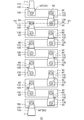
- FIG. 1 is a plan view showing a schematic structure of an assembled battery in which a plurality of batteries (single cells) are connected by a bus bar (terminal connection member) formed of a dissimilar metal joined body according to the embodiment.
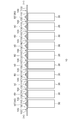
- FIG. 2 is a side view showing a schematic structure of the assembled battery.
- the assembled battery 10 includes a plurality of batteries 30 and a bus bar 100 that connects these batteries 30.
- a total of ten batteries 30 are connected in series to form the assembled battery 10. Note that the number of the batteries 30 is not particularly limited.
- the ten batteries 30 are arranged in parallel at a predetermined interval so that the longitudinal directions of the batteries 30 are substantially parallel in a plan view.
- the tip portions of the positive electrode terminal 50 and the negative electrode terminal 60 of the battery 30 protrude from the upper surface of the casing of the battery 30.
- the positive electrode terminal 50 and the negative electrode terminal 60 of the adjacent battery 30 are arranged so as to be opposite to each other.
- One negative terminal 60 and the other positive terminal 50 of the two batteries 30 adjacent to each other are electrically connected by the bus bar 100, and ten batteries 30 are connected in series.
- a first metal body 110 (to be described later) of the bus bar 100 is connected to the negative electrode terminal 60 of one battery 30, and a second metal body 130 (to be described later) of the bus bar 100 is connected to the positive electrode terminal 50 of the other battery 30. Both are electrically connected.
- the battery 30 is housed in a housing (not shown) and protected from the external environment.
- the negative terminal 60 ′ serving as one end of the series connection of the batteries 30 and the positive terminal 50 ′ serving as the other terminal can be connected to an external load (both not shown) via wiring drawn outside the housing. It has become.
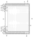
- FIG. 3 is a cross-sectional view showing a schematic structure of the battery.
- FIG. 3 corresponds to a cross-sectional view taken along line AA in FIG.
- the battery 30 includes an outer can (housing) 31 in which an electrode body 32 in which positive and negative electrodes are wound in a spiral shape is housed laterally with respect to the can axis direction of the outer can 31.
- the opening of the outer can 31 is sealed by the sealing plate 33.
- the sealing plate 33 is provided with a positive electrode terminal 50 and a negative electrode terminal 60 that protrude outward from the battery 30.
- the sealing plate 33 is formed with a gas discharge valve (not shown).
- the positive electrode terminal 50 is fitted in the positive electrode opening 33 a of the sealing plate 33 while being in contact with the gasket 34.
- the positive electrode terminal 50 is connected to the positive electrode tab member 53 on the battery inner side of the sealing plate 33.
- the end of the positive electrode terminal 50 is provided with a recess 51 in which a side wall is formed along the positive electrode opening 33a.
- the positive electrode terminal 50 is fixed to the positive electrode tab member 53 by caulking so that the edge portion of the recess 51 is widened.
- the positive electrode terminal 50 is entirely made of aluminum.
- An insulating plate 35 is provided between the positive electrode tab member 53 and the battery inner surface of the sealing plate 33.
- the insulating plate 35 and the gasket 34 are in contact with each other at the positive electrode opening 33a.
- the positive electrode tab member 53 and the positive electrode terminal 50 are insulated from the sealing plate 33.
- the positive electrode tab member 53 is connected to the positive electrode current collector plate group 32 a protruding from one end face of the electrode body 32.
- the positive electrode current collector plate group 32 a is a bundle of a plurality of positive electrode current collector plates protruding from one end face of the electrode body 32.
- the second metal body 130 portion of the bus bar 100 is fixed to the positive terminal 50 with screws. Specifically, the positive terminal 50 protruding from the positive opening 33 a is fitted into the opening 100 a provided in the second metal body 130 of the bus bar 100, and the fixing screw 80 is screwed into the positive terminal 50. As a result, the bus bar 100 is fixed to the positive electrode terminal 50 while being sandwiched between the gasket 34 and the fixing screw 80.
- the negative electrode terminal 60 is fitted in the negative electrode opening 33 b of the sealing plate 33 while being in contact with the gasket 34.
- the negative electrode terminal 60 is connected to the negative electrode tab member 62 inside the sealing plate 33 on the battery side.
- a recess 61 is formed at the end of the negative electrode terminal 60 so that a side wall is formed along the negative electrode opening 33b.
- the negative electrode terminal 60 is fixed to the negative electrode tab member 62 by caulking so that the edge portion of the recess 61 is widened.
- the entire negative electrode terminal 60 is made of copper.
- An insulating plate 35 is provided between the negative electrode tab member 62 and the battery inner surface of the sealing plate 33.
- the insulating plate 35 and the gasket 34 are in contact with each other at the negative electrode opening 33b.
- the negative electrode tab member 62 and the negative electrode terminal 60 are insulated from the sealing plate 33.
- the negative electrode tab member 62 is connected to the negative electrode current collector plate group 32 b protruding from the other end face of the electrode body 32.
- the negative electrode current collector plate group 32 b is a bundle of a plurality of negative electrode current collector plates protruding from the other end face of the electrode body 32.
- the first metal body 110 portion of the bus bar 100 is fixed to the negative electrode terminal 60 with screws. Specifically, the negative electrode terminal 60 protruding from the negative electrode opening 33 b is fitted into the opening 100 a provided in the first metal body 110 of the bus bar 100, and the fixing screw 80 is screwed into the negative electrode terminal 60. Thereby, the bus bar 100 is fixed to the negative electrode terminal 60 while being sandwiched between the gasket 34 and the fixing screw 80.
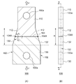
- FIG. 4 (A) is a horizontal sectional view showing a schematic structure of the bus bar
- FIG. 4 (B) is a side view showing a schematic structure of the bus bar.
- FIG. 4A corresponds to a cross-sectional view taken along line BB in FIG.
- the bus bar 100 is formed of a first metal body 110 made of a metal containing copper as a main component and a metal containing aluminum as a main component. It is comprised with the dissimilar metal joining body provided with the 2nd metal body 130 joined to the 1 metal body 110.
- “having main component” means that the content of copper or aluminum is greater than 50%, and the first metal body 110 And the Young's modulus ratio of the second metal body 130 means that other inclusions are included in a range in which the Young's modulus ratio of copper and aluminum can be considered to be equal (for example, a value approximately equal to 130 MPa / 70.3 MPa).
- the side surface of the first metal body 110 is the two side surfaces 102 (joint body side surfaces) of the bus bar 100 or the dissimilar metal joined body from which the end portion 104X of the boundary surface 104 between the first metal body 110 and the second metal body 130 is exposed.
- 112 and the side surface 132 of the second metal body 130 are smoothly continuous.
- the two side surfaces 102 of the bus bar 100 are tapered such that portions extending in the region R including the boundary surface 104 are inclined with respect to the major axis of the bus bar 100.
- a side surface 112 of a certain first metal body 110 and a side surface 132 of the second metal body 130 are located on the same plane.
- this region R will be referred to as a taper region R as appropriate.
- an intersection line between the side surface 112 of the first metal body 110 and the boundary surface 104 that is, a tangential plane of the side surface 112 of the first metal body 110 passing through the end 104X and a tangential plane of the boundary surface 104 passing through the intersection line.
- the positional relationship between the boundary surface 104 and the side surface 102 of the bus bar 100 is determined so that the formed angle ⁇ 1 is included in an angle region less than 90 ° or greater than 116 °.
- the angle ⁇ 1 formed with the tangent to the boundary surface 104 passing through the end 104X is an angle of less than 90 ° or greater than 116 °.
- the side surface 112 of the first metal body 110 is a plane in the region R
- the tangential plane of the side surface 112 in the region R coincides with the side surface 112.
- the boundary surface 104 is also a plane
- the tangent plane of the boundary surface 104 coincides with the boundary surface 104. Therefore, the angle formed by the side surface 112 of the first metal body 110 and the boundary surface 104 is included in the angle region described above.
- the tangent to the side surface 132 passing through the end portion 104X and the end An angle ⁇ 2 formed with a tangent to the boundary surface 104 passing through the portion 104X is ⁇ 1 .
- a force in a direction perpendicular to the boundary surface 104 and in which the first metal body 110 and the second metal body 130 are separated from each other is applied to the dissimilar metal joined body.
- the stress ⁇ generated on the boundary surface 104 is obtained using a polar coordinate system with the end 104X as the origin, and can be expressed by the following equation (1).
- Equation (1) ⁇ is the order of stress singularity, K is a generalized stress intensity factor, and r is the distance on the boundary surface 104 from the end 104X.
- ⁇ is the order of stress singularity
- K is a generalized stress intensity factor
- r is the distance on the boundary surface 104 from the end 104X.
- Equation (2) The order ⁇ of stress singularity in equation (1) can be expressed by the following characteristic equation (equation (2)).
- P of Formula (2) can be calculated
- ⁇ and ⁇ in equation (3) are Dundurs parameters, ⁇ is represented by the following equation (4), and ⁇ is represented by the following equation (5).
- G 1 and G 2 in the formulas (4) and (5) are represented by the following formula (6), and m 1 and m 2 are represented by the following formula (7).
- E i and ⁇ i in formula (6) and formula (7) are the Young's modulus and Poisson's ratio of the i-th metal body.
- the Young's modulus and Poisson's ratio of copper, which is the main component of the first metal body 110, are 130 MPa and 0.35, respectively, corresponding to E 1 and ⁇ 1 .
- the Young's modulus and Poisson's ratio of aluminum, which is the main component of the second metal body 130, are 70.3 MPa and 0.35, respectively, corresponding to E 2 and ⁇ 2 .
- m i of Equation (7) is plane strain.
- FIG. 5 is a graph showing the relationship between the stress singularity order ⁇ and the angle ⁇ 1 formed by the side surface 112 and the boundary surface 104.
- the relationship between the stress singularity order ⁇ and the angle ⁇ 1 obtained from the equations (2) to (14) is as shown in the graph of FIG.
- the point b corresponds to a conventional structure in which the side surface 102 and the boundary surface 104 of the dissimilar metal joined body are in perpendicular contact with each other. Therefore, in the angle region C between the point b and the point c, the order ⁇ of the stress singularity is larger than that in the conventional structure.
- the angle ⁇ 1 is less than 90 ° or exceeds 116 °, that is, the angle regions A and B where the angle ⁇ 1 is 0 ° ⁇ 1 ⁇ 90 °, or the angle ⁇ 1 is 116 ° ⁇ 1 ⁇ 180.
- the angle regions D and E where the angle is ° the order ⁇ of the stress singularity is smaller than that of the conventional structure. Therefore, the angle ⁇ 1 formed by the tangent plane of the side surface 112 of the first metal body 110 passing through the end portion 104X and the tangential plane of the boundary surface 104 passing through the end portion 104X is included in an angle region that is less than 90 ° or greater than 116 °. In this case, the stress ⁇ generated at the end portion 104X can be reduced as compared with the conventional structure.
- the angle ⁇ 1 formed between the side surface 112 and the boundary surface 104 is larger than the angle ⁇ 2 formed between the side surface 132 and the boundary surface 104. small. Therefore, the cross-sectional area of the dissimilar metal joined body parallel to the boundary surface 104 is continuous from the second metal body 130 side to the first metal body 110 side in at least a part of the region including the boundary surface 104, here, the tapered region R. Is decreasing.
- the electrical resistivity ⁇ Cu of copper as the main component of the first metal body 110 and aluminum as the main component of the second metal body 130 is 1.68 ⁇ 10 ⁇ 8 ⁇ m and 2.65 ⁇ 10 ⁇ 8 ⁇ m, respectively. is there.
- the thermal conductivities ⁇ Cu of copper and aluminum are 398 W / mK and 236 W / mK, respectively. Therefore, the side surface 102 is tapered by making the cross-sectional area of the second metal body 130 having a higher electrical resistivity and lower thermal conductivity than the first metal body 110 larger than the cross-sectional area of the first metal body 110. Therefore, it is possible to suppress a decrease in conductivity and heat conductivity of the dissimilar metal joined body.
- the densities of copper and aluminum are 2.7 g / cm 3 and 8.92 g / cm 3 , respectively. Therefore, by making the cross-sectional area of the second metal body 130 larger than the cross-sectional area of the first metal body 110, the second metal body 130 having a density lower than that of the first metal body 110 can be increased. Thereby, weight reduction of a dissimilar metal joined body can be achieved. Therefore, when the angle ⁇ 1 formed between the side surface 112 and the boundary surface 104 is less than 90 ° and the cross-sectional area of the dissimilar metal joined body is decreased from the second metal body 130 side to the first metal body 110 side, the dissimilar metal The joined body can be more suitably employed as a bus bar.
- the side surface 102 has a partial area on the same plane including a portion where the end 104X of the boundary surface 104 is exposed. That is, the portion included in the tapered region R in the side surface 102 is on the same plane.
- the side surface 102 has a taper region R partially extending, and a portion outside the taper region R extends parallel to the major axis of the dissimilar metal joined body.
- the portion near the side surface of the first metal body 110 Since it is possible to avoid the portion near the side surface of the first metal body 110 from becoming extremely small, when a dissimilar metal joined body is used as a bus bar, the conductivity or heat conductivity in the portion is reduced, The situation where connection becomes difficult can be avoided.
- the portion near the side surface of the second metal body 130 can be prevented from becoming extremely large, when the dissimilar metal joined body is used as the bus bar, the width dimension of the bus bar is increased and the assembled battery 10 is increased in size. The situation can be avoided.
- the angle ⁇ 1 formed by the side surface 112 and the boundary surface 104 is an angle included in the smaller angle region A of the angle regions A and B less than 90 °, or the angle regions D and E larger than 116 °. Even if it is a case where it is an angle included in the larger angle area
- the shape of the dissimilar metal joined body can be made to be a more suitable shape as a bus bar.
- the stress reduction effect obtained by setting the angle ⁇ 1 formed by the side surface 112 and the boundary surface 104 to the above-described angle region can be obtained in the range of the nanometer order from the end 104X, for example, in the region of 1 nm from the end 104X.
- 112 and 132 and the boundary surface 104 may be flat. Therefore, the side surface 112 of the first metal body 110, the side surface 132 of the second metal body 130, and the boundary surface 104 do not have to be flat except for the planar region in the vicinity of the end 104X.
- the boundary surface 104 may be a curved surface that is curved toward the first metal body 110 or the second metal body 130, or a refractive surface, except for the planar region.
- region may become a curved surface by the deburring process etc. in the manufacturing process of a dissimilar metal joined body.
- the dissimilar metal joined body having the above-described configuration can be manufactured, for example, as follows. First, the block of the first metal body 110 and the block of the second metal body 130 are pressure-bonded to form a clad material. Then, the clad material is sliced in a direction perpendicular to the interface 104 between the first metal body 110 and the second metal body 130 to form a plate-like clad material having a predetermined thickness. Then, the outer peripheral part of a plate-shaped clad material is cut, and a dissimilar metal joined body is manufactured. Moreover, the opening 100a is provided in the predetermined area
- the dissimilar metal joined body is formed of the first metal body 110 made of a metal containing copper as a main component and the metal containing aluminum as a main component. 110 and a second metal body 130 joined to 110.
- the side surface 112 of the first metal body 110 and the side surface 132 of the second metal body 130 are smoothly continuous on the side surface 102 where the end 104X of the boundary surface 104 between the first metal body 110 and the second metal body 130 is exposed.
- an angle formed between the tangent plane of the side surface 112 of the first metal body 110 passing through the intersection line between the side surface 112 of the first metal body 110 and the boundary surface 104 and the tangent plane of the boundary surface 104 passing through the intersection line is 90.
- the bus bar 100 includes the dissimilar metal joined body having the above-described structure, the first metal body 110 is connected to one negative electrode terminal 60 of two adjacent batteries 30, and the other positive electrode terminal 50 is connected.
- the 2nd metal body 130 is connected and both are electrically connected. According to the dissimilar metal joined body according to the present embodiment, it is possible to suppress the stress ⁇ from concentrating on the end portion 104X of the boundary surface 104 and causing the dissimilar metal joined body to break down. When used for 100, the connection reliability of the bus bar 100 can be improved.
- the present invention is not limited to the above-described embodiment, and various modifications such as design changes can be added based on the knowledge of those skilled in the art.
- the embodiment to which such a modification is added is also the present embodiment. It can be included in the scope of the invention.
- FIG. 6 is a horizontal sectional view showing a schematic structure of a bus bar composed of a dissimilar metal joined body according to a modification.
- the side surface 102 may be entirely on the same plane. That is, the side surface 102 may extend from one side surface of the bus bar 100 where the tapered region R faces the boundary surface 104 to the other side surface.
- the manufacturing process of the dissimilar metal joined body or the bus bar 100 can be further simplified.
- the angle ⁇ 1 formed between the side surface 112 and the boundary surface 104 is the above-described angle range in both of the two side surfaces 102 where the end portion 104X of the boundary surface 104 is exposed.
- the angle theta 1 is only to be the angular range mentioned above. Even in this case, since the stress reduction effect described above can be exhibited on the one side surface 102, it is possible to suppress the destruction of the dissimilar metal joined body as compared with the conventional structure.
- 30 battery 50, 50 'positive terminal, 60, 60' negative terminal, 100 bus bar, 102 side surface, 104 boundary surface, 104X end, 110 first metal body, 112 side surface, 130 second metal body, 132 side surface.
- the present invention can be used for a dissimilar metal joined body and a terminal connecting member that is composed of the dissimilar metal joined body and connects between terminals of adjacent batteries.
Landscapes
- Connection Of Batteries Or Terminals (AREA)
Abstract
本発明は、異種金属接合体の破壊を抑制することができる技術の提供を目的とする。 異種金属接合体は、銅を主成分とする金属で形成された第1金属体(110)と、アルミニウムを主成分とする金属で形成され、第1金属体(110)に接合された第2金属体(130)と、を備える。第1金属体(110)と第2金属体(130)の境界面(104)の端部(104X)が露出する異種金属接合体の1以上の接合体側面において、第1金属体(110)の側面(112)および第2金属体(130)の側面(132)が滑らかに連続し、第1金属体(110)の側面(112)と境界面(104)との交線を通る第1金属体(110)の側面(112)の接平面と、交線を通る境界面(104)の接平面とのなす角度θ1が、90°未満または116°より大きい角度領域に含まれる。
Description
本発明は、異種金属接合体と、当該異種金属接合体で構成され、隣接する電池の端子間を接続するための端子接続部材に関する。
一般にリチウムイオン電池は、アルミニウムからなる正極端子と銅からなる負極端子とを有する。複数のリチウムイオン電池を直列接続する場合、アルミニウムおよび銅を接合した異種金属接合体からなるバスバーが用いられる場合がある。この場合、バスバーは、アルミニウム部分が隣接する2つの電池の一方の正極端子に接続され、銅部分が他方の負極端子に接続される。
また、リチウムイオン電池の電池端子構造として、電池素子に接続されるアルミニウム部分と当該アルミニウム部分に接合され電池筐体外部に延出する銅部分とからなる異種金属接合体を備えた構造が知られている。(特許文献1参照)。
アルミニウムと銅が接合された異種金属接合体は、アルミニウム部分と銅部分とが互いに反対方向に引っ張られた場合、両部分の境界面の端部に応力が集中する。そのため、異種金属接合体は、当該境界面の端部から剥離などの破壊が進行しやすいという課題があった。
本発明はこうした課題に鑑みてなされたものであり、その目的は、異種金属接合体の破壊を抑制することができる技術の提供にある。
本発明のある態様は、異種金属接合体である。当該異種金属接合体は、銅を主成分とする金属で形成された第1金属体と、アルミニウムを主成分とする金属で形成され、第1金属体に接合された第2金属体と、を備え、第1金属体と第2金属体の境界面の端部が露出する本異種金属接合体の1以上の接合体側面において、第1金属体の側面および第2金属体の側面が滑らかに連続し、第1金属体の側面と境界面との交線を通る第1金属体の側面の接平面と、交線を通る境界面の接平面とのなす角度が、90°未満または116°より大きい角度領域に含まれることを特徴とする。
この態様によれば、境界面の端部に応力が集中することを抑制することができるため、異種金属接合体の破壊を抑制することができる。
上述した態様において、上述した角度は、78°以下または127°以上の角度領域に含まれてもよい。
上述したいずれかの態様において、境界面に平行な異種金属接合体の断面積は、境界面を含む少なくとも一部の領域において第2金属体側から第1金属体側にかけて連続的に減少してもよい。
上述したいずれかの態様において、接合体側面は、境界面の端部が露出する部分を含む一部の領域が同一平面上にあってもよい。あるいは、接合体側面は、全体が同一平面上にあってもよい。
本発明のある態様は、端子接続部材である。当該端子接続部材は、上述したいずれかの態様の異種金属接合体を備え、隣接する2つの電池の一方の負極端子に第1金属体が接続され、他方の正極端子に第2金属体が接続されて、両者を電気的に接続することを特徴とする。
本発明によれば、異種金属接合体の破壊を抑制することができる。
以下、本発明の実施形態を図面を参照して説明する。なお、すべての図面において、同様な構成要素には同様の符号を付し、適宜説明を省略する。
図1は、実施形態に係る異種金属接合体で構成されたバスバー(端子接続部材)により複数の電池(単セル)が連結されてなる組電池の概略構造を示す平面図である。図2は、組電池の概略構造を示す側面図である。図1および図2に示すように、組電池10は、複数の電池30と、これらの電池30を接続するバスバー100とを有する。本実施形態では、計10個の電池30が直列に接続されて組電池10が形成されている。なお、電池30の数は特に限定されない。
10個の電池30は、平面視で電池30の長手方向が略平行になるように所定の間隔で並設されている。電池30の正極端子50および負極端子60の先端部分は、電池30の筐体上面から突出している。隣接する電池30の正極端子50および負極端子60は、互いに反対側になるように配列されている。互いに隣接する2つの電池30の一方の負極端子60と他方の正極端子50とがバスバー100により電気的に接続されて、10個の電池30が直列接続されている。具体的には、一方の電池30の負極端子60にバスバー100の後述する第1金属体110が接続され、他方の電池30の正極端子50にバスバー100の後述する第2金属体130が接続されて、両者が電気的に接続されている。
電池30は、ハウジング(図示せず)内に収容されて外部環境から保護される。電池30の直列接続の一方の終端となる負極端子60’および他方の終端となる正極端子50’は、ハウジングの外部に引き回される配線を介して外部負荷(ともに図示せず)と接続可能になっている。
図3は、電池の概略構造を示す断面図である。図3は、図1におけるA-A線に沿った断面図に相当する。図3に示すように、電池30は、外装缶(筐体)31内に、正負極が渦巻状に巻回されてなる電極体32が外装缶31の缶軸方向に対し横向きに収納されており、封口板33により外装缶31の開口が封口されている。封口板33には電池30の外方に突出した正極端子50と負極端子60が設けられている。また、封口板33には、ガス排出弁(図示せず)が形成されている。
正極端子50は、ガスケット34に当接された状態で、封口板33の正極用開口33aに嵌め込まれている。また、正極端子50は、封口板33の電池内側において正極タブ部材53と接続している。なお、正極端子50の端部には、正極用開口33aに沿って側壁が形成されるような凹部51が設けられている。凹部51の縁部分が広がるようにかしめることで、正極端子50が正極タブ部材53に対して固定されている。正極端子50は全体がアルミニウムで形成されている。
正極タブ部材53と封口板33の電池内側面との間には、絶縁板35が設けられている。正極用開口33aにおいて、絶縁板35とガスケット34とが当接している。これにより、正極タブ部材53および正極端子50が封口板33から絶縁されている。正極タブ部材53は、電極体32の一方の端面から突出した正極集電板群32aに接続されている。なお、正極集電板群32aは、電極体32の一方の端面から突出した複数の正極集電板を束ねたものである。
正極端子50には、バスバー100の第2金属体130部分がねじ止め固定されている。具体的には、バスバー100の第2金属体130に設けられた開口100aに正極用開口33aから突出した正極端子50が嵌め込まれ、さらに正極端子50に固定用ねじ80が螺合している。これにより、バスバー100は、ガスケット34と固定用ねじ80とに挟まれた状態で正極端子50に固定されている。
負極端子60は、ガスケット34に当接された状態で、封口板33の負極用開口33bに嵌め込まれている。また、負極端子60は、封口板33の電池内側において負極タブ部材62と接続している。なお、負極端子60の端部には、負極用開口33bに沿って側壁が形成されるような凹部61が設けられている。凹部61の縁部分が広がるようにかしめることで、負極端子60が負極タブ部材62に対して固定されている。負極端子60は全体が銅で形成されている。
負極タブ部材62と封口板33の電池内側面との間には、絶縁板35が設けられている。負極用開口33bにおいて、絶縁板35とガスケット34とが当接している。これにより、負極タブ部材62および負極端子60が封口板33から絶縁されている。負極タブ部材62は、電極体32の他方の端面から突出した負極集電板群32bに接続されている。なお、負極集電板群32bは、電極体32の他方の端面から突出した複数の負極集電板を束ねたものである。
負極端子60には、バスバー100の第1金属体110部分がねじ止め固定されている。具体的には、バスバー100の第1金属体110に設けられた開口100aに負極用開口33bから突出した負極端子60が嵌め込まれ、さらに負極端子60に固定用ねじ80が螺合している。これにより、バスバー100は、ガスケット34と固定用ねじ80とに挟まれた状態で負極端子60に固定されている。
図4(A)は、バスバーの概略構造を示す水平断面図であり、図4(B)は、バスバーの概略構造を示す側面図である。図4(A)は、図4(B)におけるB-B線に沿った断面図に相当する。図4(A)および図4(B)に示すように、バスバー100は、銅を主成分とする金属で形成された第1金属体110と、アルミニウムを主成分とする金属で形成され、第1金属体110に接合された第2金属体130とを備える異種金属接合体で構成されている。ここで、「銅を主成分とする」および「アルミニウムを主成分とする」という表現中、「主成分とする」は、銅またはアルミニウムの含有量が50%よりも大きく、第1金属体110と第2金属体130のヤング率比が銅とアルミニウムのヤング率比に等しいとみなせる範囲(例えば、130MPa/70.3MPaに概ね等しい値)で他の含有物を含むことを意味する。
また、第1金属体110と第2金属体130の境界面104の端部104Xが露出するバスバー100あるいは異種金属接合体の2つの側面102(接合体側面)において、第1金属体110の側面112および第2金属体130の側面132が滑らかに連続している。本実施形態では、バスバー100の2つの側面102は、境界面104を含む領域R内に延在する部分がバスバー100の長軸に対して傾斜したテーパ状となっており、この領域R内にある第1金属体110の側面112および第2金属体130の側面132が同一平面上に位置している。以下、適宜この領域Rをテーパ領域Rと称する。
そして、第1金属体110の側面112と境界面104との交線、すなわち端部104Xを通る第1金属体110の側面112の接平面と、交線を通る境界面104の接平面とのなす角度θ1が、90°未満または116°より大きい角度領域に含まれるように、境界面104とバスバー100の側面102との位置関係が定められている。すなわち、側面102と接続し、端部104Xが露出する異種金属接合体の他の面、ここでは異種金属接合体の主表面を平面視したときに、端部104Xを通る側面112の接線と、端部104Xを通る境界面104の接線とのなす角度θ1が、90°未満または116°より大きい角度となっている。
なお、本実施形態では、第1金属体110の側面112は領域Rにおいて平面であるため、領域Rにおいて側面112の接平面は側面112と一致する。また、境界面104も平面であるため、境界面104の接平面は境界面104と一致する。したがって、第1金属体110の側面112と境界面104とのなす角度が上述した角度領域に含まれている。また、上述したように、テーパ領域Rにおいて第1金属体110および第2金属体130の側面112,132が同一平面上に位置しているため、端部104Xを通る側面132の接線と、端部104Xを通る境界面104の接線とのなす角度θ2は、π-θ1である。
ここで、境界面104に対して垂直でかつ第1金属体110と第2金属体130とが互いに離れる方向(図4(A)において矢印Fで示す方向)の力が異種金属接合体にかかった場合に境界面104に発生する応力σは、端部104Xを原点とする極座標系を用いて求められ、以下の式(1)で表すことができる。

式(1)において、λは応力特異性のオーダー、Kは一般化応力拡大係数、rは端部104Xからの境界面104上の距離をそれぞれ表す。式(1)から分かるように、λが0でない場合、端部104X(r=0)において応力σが無限大となる。一方、λが0である場合、端部104Xにおいて無限大になるという応力の特異性が消失する。
式(1)の応力特異性のオーダーλは、以下の特性方程式(式(2))で表すことができる。

式(2)のpは以下の式(3)から求めることができる。

式(3)におけるαおよびβは、Dundursのパラメータであり、αは以下の式(4)で表され、βは以下の式(5)で表される。


式(4)および式(5)におけるG1およびG2は、以下の式(6)で表され、m1およびm2は、以下の式(7)で表される。


式(6)および式(7)におけるEiおよびνiは、第i金属体のヤング率およびポアソン比である。第1金属体110の主成分である銅のヤング率およびポアソン比は、それぞれ130MPaおよび0.35であり、E1、ν1に相当する。第2金属体130の主成分であるアルミニウムのヤング率およびポアソン比は、それぞれ70.3MPaおよび0.35であり、E2、ν2に相当する。また、式(7)のmiは、平面ひずみである。
また、式(3)におけるA~Fは、以下の式(8)~式(13)で表される。さらに、式(8)~式(13)におけるHは、以下の式(14)で表される。
図5は、応力特異性のオーダーλと、側面112と境界面104とのなす角度θ1との関係を示すグラフである。上述した式(2)~式(14)から得られる応力特異性のオーダーλと角度θ1との関係は、図5に示すグラフのようになる。当該グラフにおいて、θ1=90°であるb点とθ1=116°であるc点における応力特異性のオーダーλが同じ値を示している。b点は、異種金属接合体の側面102と境界面104とが垂直に接する従来の構造に相当する。したがって、b点からc点の間の角度領域Cにおいて、従来の構造に比べて応力特異性のオーダーλが大きくなる。
一方、角度θ1が90°未満または116°を越えると、すなわち、角度θ1が0°<θ1<90°となる角度領域A,B、または角度θ1が116°<θ1<180°となる角度領域D,Eにおいて、応力特異性のオーダーλが従来構造に比べて小さくなる。したがって、端部104Xを通る第1金属体110の側面112の接平面と、端部104Xを通る境界面104の接平面とのなす角度θ1が90°未満または116°を越える角度領域に含まれる場合に、端部104Xに発生する応力σを従来構造に比べて小さくすることができる。
さらに、θ1=78°であるa点、またはθ1=127°であるd点において応力特異性のオーダーλが0になる。したがって、角度θ1が78°以下、すなわち0°<θ1≦78°である角度領域A、または角度θ1が127°以上、すなわち127°≦θ1<180°である角度領域Eにおいて、応力特異性のオーダーλをより小さくすることができる。したがって、角度θ1が78°以下または127°以上の角度領域に含まれる場合に、端部104Xに発生する応力σを従来構造に比べてより小さくすることができる。
また、図4(A)に示すように、本実施形態に係る異種金属接合体では、側面112と境界面104とのなす角度θ1が側面132と境界面104とのなす角度θ2よりも小さい。したがって、境界面104に平行な異種金属接合体の断面積は、境界面104を含む少なくとも一部の領域、ここではテーパ領域Rにおいて、第2金属体130側から第1金属体110側にかけて連続的に減少している。
第1金属体110の主成分である銅および第2金属体130の主成分であるアルミニウムの電気抵抗率ρCuは、それぞれ1.68×10⁻⁸Ωmおよび2.65×10⁻⁸Ωmである。また、銅およびアルミニウムの熱伝導率κCuは、それぞれ398W/mKおよび236W/mKである。そのため、第1金属体110よりも電気抵抗率が大きく熱伝導率が小さい第2金属体130の断面積を第1金属体110の断面積よりも大きくすることで、側面102をテーパ状としたことによる異種金属接合体の導電性および伝熱性の低下を抑制することができる。また、銅およびアルミニウムの密度は、それぞれ2.7g/cm3および8.92g/cm3である。そのため、第2金属体130の断面積を第1金属体110の断面積よりも大きくすることで、第1金属体110よりも密度の小さい第2金属体130を大きくすることができる。これにより、異種金属接合体の軽量化を図ることができる。したがって、側面112と境界面104とのなす角度θ1を90°未満として異種金属接合体の断面積を第2金属体130側から第1金属体110側にかけて減少させた場合には、異種金属接合体をバスバーとしてより好適に採用可能となる。
本実施形態に係る異種金属接合体において、側面102は、境界面104の端部104Xが露出する部分を含む一部の領域が同一平面上にある。すなわち、側面102のうちテーパ領域Rに含まれる部分が同一平面上にある。言い換えれば、側面102は、一部にテーパ領域Rが延在し、テーパ領域Rよりも外側の部分は異種金属接合体の長軸に平行に延びている。これにより、第1金属体110の境界面104と対向する側面近傍部分が極端に小さくなることや、第2金属体130の境界面104と対向する側面近傍部分が極端に大きくなることを回避できる。第1金属体110の側面近傍部分が極端に小さくなることを回避できることで、異種金属接合体をバスバーとして用いた場合に、当該部分において導電性や伝熱性が低下したり、負極端子60への接続が困難になる事態を回避することができる。また、第2金属体130の側面近傍部分が極端に大きくなることを回避できることで、異種金属接合体をバスバーとして用いた場合に、バスバーの幅寸法が大型化し、組電池10の大型化を招く事態を回避することができる。
したがって、側面112と境界面104とのなす角度θ1を、90°未満の角度領域A,Bのうちより小さい角度領域Aに含まれる角度とした場合、あるいは116°より大きい角度領域D,Eのうちより大きい角度領域Eに含まれる角度とした場合であっても、バスバーとして好適に採用可能な形状を維持することができる。よって、異種金属接合体をバスバーに採用した場合における、側面112と境界面104とのなす角度θ1の設定自由度を高めることができる。
なお、側面112と境界面104とのなす角度θ1を、角度領域Bあるいは角度領域Dに含まれる角度とした場合は、異種金属接合体の形状をバスバーとしてより好適な形状とすることができる。
なお、側面112と境界面104とのなす角度θ1を上述した角度領域とすることで得られる応力低減効果は、端部104Xからナノメートルオーダーの範囲、たとえば端部104Xから1nmの領域で側面112,132および境界面104が平面状であればよい。したがって、第1金属体110の側面112、第2金属体130の側面132および境界面104は、この端部104X近傍の平面状領域を除く領域が平面でなくてもよい。たとえば、境界面104は、平面状領域を除く領域が、第1金属体110側あるいは第2金属体130側に湾曲した曲面や、屈折面であってもよい。また、側面112,132は、平面状領域を除く領域が、異種金属接合体の製造工程におけるバリ取り加工などによって曲面となっていてもよい。
上述した構成を備えた異種金属接合体は、例えば次のようにして製造することができる。まず、第1金属体110のブロックと第2金属体130のブロックとが圧着接合されてクラッド材が形成される。そして、クラッド材が第1金属体110と第2金属体130の境界面104に垂直な方向にスライスされて所定厚さの板状クラッド材が形成される。その後、板状クラッド材の外周部がカットされて異種金属接合体が製造される。また、この異種金属接合体の所定領域に開口100aが設けられて、バスバー100が製造される。
以上説明したように、本実施形態に係る異種金属接合体は、銅を主成分とする金属で形成された第1金属体110と、アルミニウムを主成分とする金属で形成され、第1金属体110に接合された第2金属体130とを備える。そして、第1金属体110と第2金属体130の境界面104の端部104Xが露出する側面102において、第1金属体110の側面112および第2金属体130の側面132が滑らかに連続している。さらに、第1金属体110の側面112と境界面104との交線を通る第1金属体110の側面112の接平面と、交線を通る境界面104の接平面とのなす角度が、90°未満または116°より大きい角度領域に含まれる。これにより、境界面104に垂直な方向の引っ張り応力が異種金属接合体にかかった際に、境界面104の端部104Xに応力σが集中することを防ぐことができる。そのため、異種金属接合体の破壊を抑制することができる。
また、本実施形態に係るバスバー100は、上述した構造の異種金属接合体を備え、隣接する2つの電池30の一方の負極端子60に第1金属体110が接続され、他方の正極端子50に第2金属体130が接続されて、両者を電気的に接続する。本実施形態に係る異種金属接合体によれば、境界面104の端部104Xに応力σが集中して異種金属接合体が破壊に至ることを抑制できるため、このような異種金属接合体をバスバー100に用いた場合には、バスバー100の接続信頼性を向上させることができる。
本発明は、上述の実施形態に限定されるものではなく、当業者の知識に基づいて各種の設計変更等の変形を加えることも可能であり、そのような変形が加えられた実施形態も本発明の範囲に含まれうるものである。
図6は、変形例に係る異種金属接合体で構成されたバスバーの概略構造を示す水平断面図である。図6に示すように、側面102は、全体が同一平面上にあってもよい。すなわち、側面102は、テーパ領域Rが境界面104と対向するバスバー100の一方の側面から他方の側面にかけて延在してもよい。この場合、異種金属接合体の輪郭形状の成形が容易になるため、異種金属接合体あるいはバスバー100の製造工程をより簡略化することができる。
上述した実施形態では、境界面104の端部104Xが露出する2つの側面102の両方において、側面112と境界面104とのなす角度θ1を上述した角度範囲としている。しかしながら、少なくとも一方の側面102において、当該角度θ1が上述した角度範囲とされていればよい。この場合であっても、当該一方の側面102において上述した応力低減効果を発揮することができるため、従来の構造に比べて異種金属接合体の破壊を抑制することができる。
30 電池、 50,50’ 正極端子、 60,60’ 負極端子、 100 バスバー、 102 側面、 104 境界面、 104X 端部、 110 第1金属体、 112 側面、 130 第2金属体、 132 側面。
本発明は、異種金属接合体と、当該異種金属接合体で構成され、隣接する電池の端子間を接続するための端子接続部材に利用することができる。
Claims (6)
- 銅を主成分とする金属で形成された第1金属体と、
アルミニウムを主成分とする金属で形成され、前記第1金属体に接合された第2金属体と、を備え、
前記第1金属体と前記第2金属体の境界面の端部が露出する本異種金属接合体の1以上の接合体側面において、前記第1金属体の側面および前記第2金属体の側面が滑らかに連続し、
前記第1金属体の側面と前記境界面との交線を通る前記第1金属体の側面の接平面と、前記交線を通る前記境界面の接平面とのなす角度が、90°未満または116°より大きい角度領域に含まれることを特徴とする異種金属接合体。 - 前記角度は、78°以下または127°以上の角度領域に含まれる請求項1に記載の異種金属接合体。
- 前記境界面に平行な異種金属接合体の断面積は、前記境界面を含む少なくとも一部の領域において前記第2金属体側から前記第1金属体側にかけて連続的に減少する請求項1または2に記載の異種金属接合体。
- 前記接合体側面は、前記境界面の端部が露出する部分を含む一部の領域が同一平面上にある請求項1乃至3のいずれか1項に記載の異種金属接合体。
- 前記接合体側面は、全体が同一平面上にある請求項1乃至3のいずれか1項に記載の異種金属接合体。
- 請求項1乃至5のいずれか1項に記載の異種金属接合体を備え、
隣接する2つの電池の一方の負極端子に前記第1金属体が接続され、他方の正極端子に前記第2金属体が接続されて、両者を電気的に接続することを特徴とする端子接続部材。
Applications Claiming Priority (2)
| Application Number | Priority Date | Filing Date | Title |
|---|---|---|---|
| JP2011019093A JP2014075179A (ja) | 2011-01-31 | 2011-01-31 | 異種金属接合体および端子接続部材 |
| JP2011-019093 | 2011-01-31 |
Publications (1)
| Publication Number | Publication Date |
|---|---|
| WO2012105161A1 true WO2012105161A1 (ja) | 2012-08-09 |
Family
ID=46602391
Family Applications (1)
| Application Number | Title | Priority Date | Filing Date |
|---|---|---|---|
| PCT/JP2012/000127 Ceased WO2012105161A1 (ja) | 2011-01-31 | 2012-01-11 | 異種金属接合体および端子接続部材 |
Country Status (2)
| Country | Link |
|---|---|
| JP (1) | JP2014075179A (ja) |
| WO (1) | WO2012105161A1 (ja) |
Families Citing this family (2)
| Publication number | Priority date | Publication date | Assignee | Title |
|---|---|---|---|---|
| JP7340778B2 (ja) * | 2018-03-28 | 2023-09-08 | パナソニックIpマネジメント株式会社 | バスバーおよび電池積層体 |
| JP2020113524A (ja) * | 2019-01-15 | 2020-07-27 | Smk株式会社 | バスバーおよびバスバーの製造方法 |
Citations (2)
| Publication number | Priority date | Publication date | Assignee | Title |
|---|---|---|---|---|
| JP2003115285A (ja) * | 2001-10-03 | 2003-04-18 | Ngk Insulators Ltd | リチウム二次単電池及びリチウム二次単電池の接続構造体 |
| JP2004255388A (ja) * | 2003-02-24 | 2004-09-16 | Toshiba Corp | 異種金属スカーフ継手を有する部材及びその設計方法 |
-
2011
- 2011-01-31 JP JP2011019093A patent/JP2014075179A/ja not_active Withdrawn
-
2012
- 2012-01-11 WO PCT/JP2012/000127 patent/WO2012105161A1/ja not_active Ceased
Patent Citations (2)
| Publication number | Priority date | Publication date | Assignee | Title |
|---|---|---|---|---|
| JP2003115285A (ja) * | 2001-10-03 | 2003-04-18 | Ngk Insulators Ltd | リチウム二次単電池及びリチウム二次単電池の接続構造体 |
| JP2004255388A (ja) * | 2003-02-24 | 2004-09-16 | Toshiba Corp | 異種金属スカーフ継手を有する部材及びその設計方法 |
Also Published As
| Publication number | Publication date |
|---|---|
| JP2014075179A (ja) | 2014-04-24 |
Similar Documents
| Publication | Publication Date | Title |
|---|---|---|
| CN101546845B (zh) | 可再充电锂电池 | |
| CN112771635B (zh) | 蓄电模块 | |
| US10923703B2 (en) | Electricity storage apparatus | |
| US10998537B2 (en) | Battery | |
| US9905833B2 (en) | Energy storage apparatus | |
| JP7304329B2 (ja) | 二次電池ならびに二次電池用端子およびその製造方法 | |
| CN106663773A (zh) | 电极构件及集电板、电池组 | |
| CN111902967B (zh) | 汇流条以及电池层叠体 | |
| CN104321906A (zh) | 双金属汇流条组件 | |
| JP2023076533A5 (ja) | ||
| US20210391617A1 (en) | Laminated battery | |
| US11728550B2 (en) | Sealed battery | |
| JP2008123800A (ja) | 電池の接続構造及び接続方法 | |
| US20180241050A1 (en) | Separator supporting structure | |
| CN107369788A (zh) | 一种动力电池顶盖组件、动力电池及电池模组 | |
| CN210325970U (zh) | 一种电池软连接件 | |
| US20120052334A1 (en) | Battery pack | |
| US10868291B2 (en) | Conductive sheet for connecting batteries and battery connecting module utilizing the same | |
| CN202217732U (zh) | 一种电池连接件及电池组 | |
| JP2014075179A (ja) | 異種金属接合体および端子接続部材 | |
| CN105185941A (zh) | 用于电池模块的电气的单池连接器 | |
| CN110770945A (zh) | 汇流条以及电池层叠体 | |
| JP7753371B2 (ja) | バスバー及び電池モジュール | |
| JP7681708B2 (ja) | 組電池 | |
| JP2009187895A (ja) | 組電池および電池パック |
Legal Events
| Date | Code | Title | Description |
|---|---|---|---|
| 121 | Ep: the epo has been informed by wipo that ep was designated in this application |
Ref document number: 12742028 Country of ref document: EP Kind code of ref document: A1 |
|
| NENP | Non-entry into the national phase |
Ref country code: DE |
|
| 122 | Ep: pct application non-entry in european phase |
Ref document number: 12742028 Country of ref document: EP Kind code of ref document: A1 |
|
| NENP | Non-entry into the national phase |
Ref country code: JP |