WO2012105122A1 - 立体視用画像撮像装置およびその動作制御方法 - Google Patents
立体視用画像撮像装置およびその動作制御方法 Download PDFInfo
- Publication number
- WO2012105122A1 WO2012105122A1 PCT/JP2011/078005 JP2011078005W WO2012105122A1 WO 2012105122 A1 WO2012105122 A1 WO 2012105122A1 JP 2011078005 W JP2011078005 W JP 2011078005W WO 2012105122 A1 WO2012105122 A1 WO 2012105122A1
- Authority
- WO
- WIPO (PCT)
- Prior art keywords
- image
- viewpoint
- search
- imaging device
- control
- Prior art date
- Legal status (The legal status is an assumption and is not a legal conclusion. Google has not performed a legal analysis and makes no representation as to the accuracy of the status listed.)
- Ceased
Links
Images












Classifications
-
- G—PHYSICS
- G03—PHOTOGRAPHY; CINEMATOGRAPHY; ANALOGOUS TECHNIQUES USING WAVES OTHER THAN OPTICAL WAVES; ELECTROGRAPHY; HOLOGRAPHY
- G03B—APPARATUS OR ARRANGEMENTS FOR TAKING PHOTOGRAPHS OR FOR PROJECTING OR VIEWING THEM; APPARATUS OR ARRANGEMENTS EMPLOYING ANALOGOUS TECHNIQUES USING WAVES OTHER THAN OPTICAL WAVES; ACCESSORIES THEREFOR
- G03B35/00—Stereoscopic photography
- G03B35/02—Stereoscopic photography by sequential recording
-
- H—ELECTRICITY
- H04—ELECTRIC COMMUNICATION TECHNIQUE
- H04N—PICTORIAL COMMUNICATION, e.g. TELEVISION
- H04N13/00—Stereoscopic video systems; Multi-view video systems; Details thereof
- H04N13/20—Image signal generators
- H04N13/204—Image signal generators using stereoscopic image cameras
- H04N13/207—Image signal generators using stereoscopic image cameras using a single two-dimensional [2D] image sensor
- H04N13/221—Image signal generators using stereoscopic image cameras using a single two-dimensional [2D] image sensor using the relative movement between cameras and objects
-
- H—ELECTRICITY
- H04—ELECTRIC COMMUNICATION TECHNIQUE
- H04N—PICTORIAL COMMUNICATION, e.g. TELEVISION
- H04N13/00—Stereoscopic video systems; Multi-view video systems; Details thereof
- H04N13/20—Image signal generators
- H04N13/204—Image signal generators using stereoscopic image cameras
- H04N13/207—Image signal generators using stereoscopic image cameras using a single two-dimensional [2D] image sensor
- H04N13/236—Image signal generators using stereoscopic image cameras using a single two-dimensional [2D] image sensor using varifocal lenses or mirrors
Definitions
- the present invention relates to a stereoscopic imaging device and an operation control method thereof.
- a camera that captures a three-dimensional image includes one having a single imaging device and two imaging devices.
- feature points are associated between adjacent images for a large number of image groups (first image group) obtained while moving the camera, and feature point association information is obtained.
- an image group (second image group) having a fixed viewpoint interval is obtained from the first image group (Japanese Patent Laid-Open No. 2006-113807).
- a stereoscopic image is constituted by the second image group.
- an image suitable for stereoscopic viewing may not be obtained.
- An object of the present invention is to obtain an image suitable for stereoscopic viewing.
- a stereoscopic image pickup device that picks up a subject and outputs image data representing the subject image, a focus lens provided in front of a light receiving surface of the solid-state electronic image pickup device, A plurality of first viewpoint images obtained by positioning the focus lens at one viewpoint (at the focus lens position for the first viewpoint) and imaging from the first viewpoint using the solid-state electronic imaging device.
- Each corresponding point of the feature point is obtained by positioning the focus lens at the second viewpoint (at the focus / lens position for the second viewpoint) and imaging from the second viewpoint using the solid-state electronic imaging device.
- a corresponding point searching means for searching from the second viewpoint image, the corresponding points of the plurality of feature points included in the first viewpoint image are A second image obtained by positioning the focus lens in either the NEAR direction or the FAR direction from the focus lens position at the second viewpoint and capturing an image from the second viewpoint using the solid-state electronic imaging device.
- the first search control means for controlling the focus lens and the corresponding point search means so as to search from the viewpoint image, from the first corresponding point number obtained by the corresponding point search means
- the first determination means for determining whether the number of second corresponding points obtained under the control of the first search control means is larger or smaller, the first determination It is determined that the number of second corresponding points obtained under the control of the first search control means is greater than the number of first corresponding points obtained by the means for searching for corresponding points. Accordingly, the position where the focus lens is positioned under the control of the first search control means is the first focus lens position at the second viewpoint (second viewpoint focus lens position).
- Update means (first update device), and the focus lens is positioned at the focus lens position (second viewpoint focus lens position) at the second viewpoint, which is positioned by the first update means.
- 3D image file generating means (stereoscopic image file generating device) for generating a stereoscopic image file using image data representing an image obtained from the first viewpoint and image data obtained from the first viewpoint. It is characterized by being.
- the first invention also provides an operation control method suitable for the stereoscopic imaging apparatus. That is, this method captures a subject and outputs image data representing the subject image, and stereoscopic imaging with a focus lens provided in front of the light-receiving surface of the solid-state electronic imaging device.
- the corresponding point search means positions the focus lens at the first viewpoint (first viewpoint focus lens position) and images from the first viewpoint using the solid-state electronic imaging apparatus.
- the corresponding points of the plurality of feature points included in the first viewpoint image obtained in this way are used to position the focus lens at the second viewpoint (second viewpoint focus / lens position) to position the solid-state electronic imaging device.
- the second viewpoint image obtained by imaging from the second viewpoint is used for searching, and the first search control means is included in the first viewpoint image.
- the corresponding feature points of the number of feature points are positioned in the NEAR direction or the FAR direction from the focus lens position at the second viewpoint, and the solid-state electronic imaging device is used to position the focus lens.
- the focus lens and the corresponding point searching means are controlled so as to search from a second viewpoint image obtained by imaging from two viewpoints, and the first determining means is the first obtained by the corresponding point searching means. It is determined whether the number of second corresponding points obtained under the control of the first search control means is larger or smaller than the number of corresponding points of 1, and the updating means uses the first determining means to In response to determining that the number of second corresponding points obtained under the control of the first search control means is greater than the number of first corresponding points obtained by the corresponding point search means, The position at which the focus lens is positioned under the control of one search control means is set as the focus lens position at the second viewpoint, and the stereoscopic image file generation means is a second position determined by the first update means.
- a stereoscopic image file is generated using image data representing an image obtained by imaging from the second viewpoint by positioning the focus lens at the focus lens position at the viewpoint and image data obtained by imaging from the first viewpoint.
- the focus lens is positioned at the first viewpoint (first viewpoint focus lens position, not the focus lens position dedicated to the first viewpoint), and the first is performed using the solid-state electronic imaging device.
- the subject is imaged from the viewpoint.
- a first viewpoint image is obtained.
- the focus lens is at the second viewpoint ⁇ the focus lens position for the second viewpoint. It is not the focus lens position dedicated to the second viewpoint.
- the position at the first viewpoint may be the same position or a different position, but at the beginning of the processing, the position will be the same as the position at the first viewpoint (first viewpoint focus / lens position). .
- the subject is imaged from the second viewpoint using the solid-state electronic imaging device after being positioned. A first second viewpoint image is obtained. Further, the focus lens is moved from the focus lens position at the second viewpoint (second viewpoint focus lens position) to a position in either the NEAR direction or the FAR direction, and the first position is determined using the solid-state electronic imaging device.
- a subject is imaged from two viewpoints.
- a second second viewpoint image is obtained. Corresponding points of a plurality of feature points included in the first viewpoint image are found from the first second viewpoint image.
- corresponding points of the plurality of feature points included in the first viewpoint image are found from the second second viewpoint image.
- the first corresponding point number representing the number of corresponding points found from the first second viewpoint image is compared with the second corresponding point number representing the number of corresponding points found from the second second viewpoint image. Is done. If the number of second corresponding points found from the second second viewpoint image is greater than the number of first corresponding points found from the first second viewpoint image, the focus at the second viewpoint
- the lens position is updated to a position in either the NEAR direction or the FAR direction.
- the focus lens is positioned at the updated focus lens position at the second viewpoint (second viewpoint focus lens position), and the subject is imaged from the second viewpoint.
- a stereoscopic image file is generated using the obtained image data representing the second viewpoint image and image data representing the first viewpoint image. It is determined that the number of second corresponding points obtained under the control of the first search control means is smaller than the number of first corresponding points obtained by the corresponding point searching means by the first determining means. In response, the corresponding points of the plurality of feature points included in the first viewpoint image are moved from the focus lens position at the second viewpoint to the focus / focus direction in either the NEAR direction or the FAR direction.
- Control means (second search control device), a third pair obtained under the control of the second search control means rather than the first corresponding point number obtained by the corresponding point search means.
- Second determination means (second determination device) for determining whether or not the score is larger, and the second corresponding value than the first corresponding score obtained by the corresponding point search means by the second determination means.
- the focus lens is positioned under the control of the second search control means in response to determining that the third corresponding number of points obtained under the control of the search control means is greater.
- a second updating means for setting the determined position as the focus lens position at the second viewpoint.
- the stereoscopic image file generation means positions the focus lens at the focus lens position at the second viewpoint positioned by the first update means or the second update means and sets the second viewpoint.
- a stereoscopic image file will be generated using image data representing an image obtained from the image and image data obtained from the first viewpoint.
- a stereoscopic image file is generated using image data representing the first viewpoint image and image data representing the second viewpoint image with many corresponding points.
- a stereoscopic image suitable for stereoscopic viewing is obtained.
- the first search control means By the corresponding point search means, the first search control means, the first determination means, the first update means, the second search control means, the second determination means, and the second update means You may further provide the control means (control device) which repeats each process.
- the position of the focus lens at the time of imaging from the second viewpoint in the corresponding point search means is the focus lens position at the first viewpoint in the first process, and the focus lens position at the second viewpoint in the subsequent processes.
- First disparity value calculating means for calculating a disparity value between a feature point and a corresponding point for each corresponding point found by the search by the corresponding point searching means
- first search control Second disparity value calculating means for calculating the disparity value between the feature point and the corresponding point for each corresponding point found by the search performed under the control of the means
- second Third parallax value calculating means for calculating a parallax value between the feature point and the corresponding point for each corresponding point found by the search performed under the control of the search control unit.
- the first determination unit is, for example, a corresponding point in which the parallax value calculated by the first parallax value calculating unit out of the number of corresponding points obtained by the corresponding point searching unit has a predetermined parallax value.
- the disparity value calculated by the second disparity value calculating means out of the number of corresponding points obtained under the control of the first search control means is the number of corresponding points having a predetermined disparity value. Whether the number is larger or smaller is determined, and the second determining means calculates, for example, by the first parallax value calculating means out of the number of corresponding points obtained by the corresponding point searching means.
- the calculated disparity value is calculated by the third disparity value calculating means out of the number of corresponding points obtained under the control of the second search control means, rather than the number of corresponding points having a predetermined disparity value.
- the number of corresponding points with a given parallax value is greater It would be those to determine.
- An image flat area detecting means image flat area detecting device for detecting an image flat area with little change in luminance or color from the second viewpoint image may be further provided.
- the search performed by the corresponding point search means, the search performed under the control of the first search control means, and the search performed under the control of the second search control means are performed on the image flat region. It is preferable to perform the remaining image area of the second viewpoint image excluding the image flat area detected by the detection means.
- a search performed by the corresponding point search unit, a search performed under the control of the first search control unit, and a search performed under the control of the second search control unit are performed on the left and right sides of the second viewpoint image. You may make it carry out about the remaining image area
- a stereoscopic image pickup apparatus is a solid-state electronic image pickup apparatus that picks up a subject and outputs image data representing the subject image, a focus lens provided in front of the light receiving surface of the solid-state electronic image pickup apparatus, First imaging control means (first imaging control device) for controlling the solid-state electronic imaging device so as to capture an image from the viewpoint, and the second position at each moving position while moving the position of the focus lens by a predetermined distance.
- First imaging control means for controlling the solid-state electronic imaging device so as to capture an image from the viewpoint, and the second position at each moving position while moving the position of the focus lens by a predetermined distance.
- second imaging control means for controlling the solid-state electronic imaging device so as to take an image from the viewpoint
- the solid-state electronic imaging device is configured to detect corresponding points of a plurality of feature points included in the first viewpoint image represented by the image data to be processed under the control of the second imaging control unit.
- Corresponding point searching means for searching from each of the plurality of second viewpoint images represented by the image data output from the second image, and the second having the most corresponding points among the plurality of second viewpoint images.
- a stereoscopic image file generating means for generating a stereoscopic image file using the image data representing the viewpoint image and the image data representing the first viewpoint image.
- the second invention also provides an operation control method suitable for the stereoscopic imaging apparatus. That is, this method captures a subject and outputs image data representing the subject image, and stereoscopic imaging with a focus lens provided in front of the light-receiving surface of the solid-state electronic imaging device.
- a first imaging control unit controls the solid-state electronic imaging device so as to capture an image from a first viewpoint
- a second imaging control unit determines the position of the focus lens by a predetermined distance.
- the solid-state electronic image pickup device is controlled so as to pick up an image from the second viewpoint at each moving position while being moved one by one, and the corresponding point search means is controlled by the first image pickup control means.
- Corresponding points of the plurality of feature points included in the first viewpoint image represented by the image data output from the device are converted into the solid-state electric power under the control of the second imaging control means.
- the second viewpoint is searched from each of the plurality of second viewpoint images represented by the image data output from the imaging device, and the stereoscopic image file generation means has the most corresponding points among the plurality of second viewpoint images.
- a stereoscopic image file is generated using image data representing an image and image data representing the first viewpoint image.
- the subject is imaged from the first viewpoint using the solid-state electronic imaging device.
- a first viewpoint image is obtained.
- the subject is imaged from the second viewpoint using the solid-state electronic imaging device while moving the position of the focus lens by a predetermined distance.
- a plurality of second viewpoint images are obtained.
- Corresponding points corresponding to each of the plurality of feature points of the first viewpoint image are found from each of the plurality of second viewpoint images.
- a stereoscopic image file is generated using image data representing the second viewpoint image having the most corresponding points among the plurality of second viewpoint images and image data representing the first viewpoint image. Since a stereoscopic image is obtained using the second viewpoint image with many corresponding points, it is suitable for stereoscopic viewing.
- the second imaging control means moves the position of the focus lens from the FAR end to the NEAR end by a predetermined distance while taking an image from the second viewpoint at each moving position.
- Disparity value calculating means (disparity value calculating device) for calculating the disparity value between the feature point and the corresponding point for each second viewpoint image for each corresponding point found by the search by the corresponding point searching means. May be.
- the stereoscopic image file generating means for example, the image data representing the second viewpoint image having the most corresponding points having a predetermined parallax value among the parallax values calculated by the parallax value calculating means and the first A stereoscopic image file will be generated using image data representing the viewpoint image.
- An image flat area detecting means (image flat area detecting device) for detecting an image flat area with little change in luminance or color may be provided.
- the corresponding point search means sets the remaining image area excluding the image flat area detected by the image flat area detection means as the range of the corresponding point search.
- the corresponding point search means may use the remaining image area excluding a predetermined area at the left and right ends of the second viewpoint image as a range of the corresponding point search.
- a stereoscopic image pickup device is a solid-state electronic image pickup device that picks up a subject and outputs image data representing the subject image, a zoom lens provided in front of a light receiving surface of the solid-state electronic image pickup device, A first imaging control means (first imaging control device) for controlling the solid-state electronic imaging device so as to take an image from a second viewpoint, and a second for controlling the solid-state electronic imaging device so as to take an image from a second viewpoint.
- Each corresponding point is searched for from the second viewpoint image represented by the image data output from the solid-state electronic imaging device under the control of the second imaging control means.
- direction determination means direction determination device for determining whether the corresponding point searched by the corresponding point searching means exists outside or inside the corresponding feature point
- the zoom lens is controlled to change to the wide side when it is determined to be present outside by the direction determining means, and to the tele side when it is determined to exist inside by the direction determining means.
- the zoom lens control means zoom / lens control device
- the image data representing the first viewpoint image and the zoom amount controlled under the control of the zoom lens control means.
- a stereoscopic image file is generated using image data representing the second viewpoint image output from the solid-state electronic imaging device under the control of the imaging control means Characterized in that it comprises a body image file generation means (stereoscopic image file generation device).
- the third invention also provides an operation control method suitable for the above-described stereoscopic imaging apparatus. That is, this method captures a subject and outputs image data representing the subject image, and stereoscopic imaging with a zoom lens provided in front of the light receiving surface of the solid-state electronic imaging device.
- the first imaging control unit controls the solid-state electronic imaging device so as to capture an image from a first viewpoint
- the second imaging control unit performs an imaging from a second viewpoint.
- the solid-state electronic image pickup device is controlled, and the corresponding point search means is included in the first viewpoint image represented by the image data output from the solid-state electronic image pickup device under the control of the first image pickup control means.
- Corresponding points of the feature points are searched from the second viewpoint image represented by the image data output from the solid-state electronic imaging device under the control of the second imaging control means,
- the determining means determines whether the corresponding point searched by the corresponding point searching means is outside or inside the corresponding feature point, and the zoom / lens control means is determined by the direction determining means.
- the zoom lens is controlled so as to change to the wide side in response to being determined to be present on the outside and to the tele side in response to being determined to be present on the inner side by the direction determining means.
- the file generation means is under the control of the second imaging control means.
- a stereoscopic image file is generated using image data representing the second viewpoint image output from the solid-state electronic imaging device.
- Corresponding points respectively corresponding to a plurality of feature points included in the first viewpoint image are found from the second viewpoint image. It is determined whether the found corresponding point exists outside or inside the feature point. When it is determined that the zoom lens exists outside, the zoom lens is changed to the wide side, and when it is determined that the zoom lens exists inside, the zoom lens is changed to the tele side. A subject is imaged from the second viewpoint with the zoom amount changed, and a stereoscopic image file is generated from the obtained image data representing the second viewpoint image and image data representing the first viewpoint image. A first viewpoint image and a second viewpoint image that are not misaligned are obtained, and a stereoscopic image suitable for stereoscopic viewing is obtained.
- a zoom amount calculation means (a zoom amount calculation device) that calculates a zoom amount based on the size of at least one of the first viewpoint image and the second viewpoint image and the extent of expansion of the corresponding point and the feature point. ) May be further provided.
- the zoom / lens control means changes to the wide side with the zoom amount calculated by the zoom amount calculation means, for example, in response to the determination by the direction determination means that it exists outside.
- the zoom lens will be controlled so that the zoom lens is changed to the tele side by the zoom amount calculated by the zoom amount calculation unit in response to the determination that the unit exists inside.
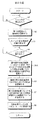
- FIG. 1 shows a state in which imaging is performed in a stereoscopic imaging mode using a digital still camera.
- FIG. 2 is a block diagram showing the electrical configuration of the digital still camera.
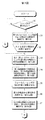
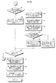
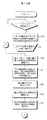
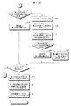
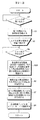
- 3 and 4 are flowcharts showing the processing procedure of the digital still camera.
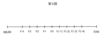
- FIG. 5 shows the position of the focus lens.
- FIG. 6 is an example of the first viewpoint image.
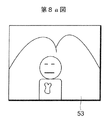
- 7a, 7b, 8a, 8b, 9a and 9b are examples of the second viewpoint image.
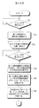
- 10 to 13 are flowcharts showing the processing procedure of the digital still camera.
- 14 to 16 are examples of the second viewpoint image.
- FIG. 17 is a flowchart showing the processing procedure of the digital still camera.
- FIG. 18 shows the focus lens position.
- FIG. 19 is an example of the second viewpoint image.
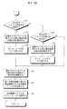
- 20 to 23 are flowcharts showing the processing procedure of the digital still camera.
- 24 and 25 show an example of the second viewpoint image.
- 26 and 27 are flowcharts showing the processing procedure of the digital still camera
- FIG. 1 shows an embodiment of the present invention.
- a digital still camera 1 (not only a digital still camera but also a movie digital camera, a still imaging function and movie imaging) It can also be applied to a digital camera having both functions.
- the digital still camera 1 obtains a stereoscopically visible image (hereinafter referred to as a stereoscopic image) from an image obtained by imaging the same subject a plurality of times.
- a stereoscopic image a stereoscopically visible image
- the position (viewpoint) of the digital still camera 1 is moved, and the subject is imaged with different viewpoints before and after the movement.
- FIG. 1 shows that the user performs the first imaging from the left eye viewpoint (reference viewpoint) using the digital still camera 1, and then moves rightward toward the subject to perform the second imaging from the right eye viewpoint.
- the positional relationship of the digital still camera 1 when performing is shown.
- an image obtained by imaging before movement is referred to as a “left-eye image” (first viewpoint image)
- an image obtained by imaging after movement in the horizontal direction is referred to as a “right-eye image” (second viewpoint image).
- Image an image obtained by imaging before movement may be referred to as a “right eye image”
- an image obtained by imaging after movement may be referred to as a “left eye image”.
- the moving direction of the user is leftward toward the subject.
- FIG. 2 is a block diagram showing an electrical configuration of the digital still camera 1.
- the overall operation of the digital still camera 1 is controlled by the CPU 2.
- the digital still camera 1 includes a solid-state electronic image pickup device (CCD, CMOS, etc.) 15.
- a pass filter (OLPF) 14 is provided.
- the zoom lens 10, the focus lens 11, the diaphragm 12, and the solid-state electronic image sensor 15 are controlled by a zoom motor 6, a focus motor 7, a diaphragm drive circuit 8, and an image sensor drive circuit 9, respectively.
- the digital still camera 1 includes an operation device 3.
- the operation unit 3 includes a power button, a mode setting dial, a two-stroke type shutter release button, and the like.
- An operation signal output from the operation device 3 is input to the CPU 2.
- the mode set by the mode setting dial includes an imaging mode and a playback mode.
- the imaging modes further include a normal imaging mode and a stereoscopic imaging mode.
- the digital still camera 1 is provided with a light emitting device 4 for strobe imaging and a light receiving device 5 for receiving reflected light of emitted light emitted from the light emitting device 4.
- the power of the digital still camera 1 is turned on and the imaging mode is set, the light beam representing the subject image passes through the imaging lens 11, the diaphragm 12, the infrared cut filter 13 and the optical low pass filter 14.
- the solid-state electronic image pickup device 15 picks up a subject with a constant period, and outputs an analog video signal representing the subject image for each frame with a constant period.
- An analog video signal representing the subject image output from the solid-state electronic image sensor 15 is input to the analog signal processing device 16.
- the analog signal processing device 16 includes a correlated double sampling circuit, a signal amplifier, and the like, where correlated double sampling, signal amplification, and the like are performed.
- the analog video signal output from the analog signal processing device 16 is input to the analog / digital conversion circuit 17 where it is converted into digital image data.
- Digital image data is provided to the memory control circuit 21 via the data bus 32.
- Digital image data is temporarily recorded in the main memory 22 under the control of the memory control circuit 21.
- the memory control circuit 21 and the like are connected to the CPU 2 by a control line 31.
- Digital image data is read from the main memory 22 and input to the digital signal processing circuit 23 via the data bus 31 or 32.
- the digital signal processing circuit 23 performs predetermined digital signal processing such as white balance adjustment and gamma correction.
- the data subjected to the digital signal processing in the digital signal processing circuit 23 is given to the display control circuit 28. When the display device 29 is controlled by the display control circuit 28, the subject image is displayed on the display screen.
- the lens 11 When the shutter release button is pressed in the first stage, the lens 11 is driven by the focus motor 7 to perform focusing. Luminance data is obtained in the digital signal processing circuit 23 based on the image data read from the main memory 22, and the luminance data is input to the integrating circuit 25 and integrated. Data representing the integrated value is given to the CPU 2 to calculate the exposure amount.
- the aperture of the aperture 12 is controlled by the aperture drive circuit 8 so that the calculated exposure amount is obtained, and the shutter speed of the solid-state electronic image sensor 15 is controlled by the image sensor drive circuit 9.
- the shutter release button When the shutter release button is pressed in the second stage, the image data captured as described above and output from the analog / digital conversion circuit 17 is recorded in the main memory 22.
- the digital signal processing circuit 23 performs predetermined digital signal processing on the image data read from the main memory 22 as described above.
- the image data output from the digital signal processing circuit 23 is compressed in the compression / decompression processing circuit 24.
- the compressed image data is recorded on the memory card 27 under the control of the external memory control circuit 26.
- the playback mode is set in the operation device 3
- the compressed image data recorded in the memory card 27 is read out.
- the read compressed image data is expanded in the compression / expansion processing circuit 24 and then supplied to the display control circuit 28.
- a reproduced image is displayed on the display screen of the display device 29.
- the digital still camera 1 can obtain a stereoscopic image.
- the stereoscopic imaging mode is selected using the mode selection dial of the operation device 3.
- FIGS. 3 and 4 are flowcharts showing the processing procedure of the digital still camera 1 when the stereoscopic imaging mode is selected.
- the first viewpoint image left eye image
- the digital still camera 1 is moved in the horizontal direction, and a plurality of second viewpoint images (right-eye images) are taken from the second viewpoint (right-eye viewpoint for capturing right-eye images). ) Is obtained.
- the position of the focus lens 11 is changed for each imaging. A feature point representing the feature is found from the first viewpoint image, and a corresponding point corresponding to the feature point is found in each of the plurality of second viewpoint images.
- a stereoscopic image file is generated from image data representing a second viewpoint image having a large number of corresponding points and image data representing the first viewpoint image. Is generated and recorded on the memory card 27.
- the digital still camera 1 is positioned at the position of the first viewpoint. If the shutter release button is depressed in the first stage and the second stage (YES in step 30), focusing is performed in accordance with the depression in the first stage as described above, and the focus lens 11 is moved. Positioning (first focus / lens position) is performed. It does not have to be a two-stroke type shutter release button.
- FIG. 5 shows the position of the focus lens 11.
- the position of the first focus lens (the focus lens position at the first viewpoint, the focus lens position for the first viewpoint) is, for example, the position F0.
- the focus lens 11 is positioned at the position F0 and imaging from the first viewpoint is performed.
- a first viewpoint image is obtained.
- FIG. 6 is an example of the first viewpoint image 51.
- the first viewpoint image 51 is a left-eye image that the viewer sees with the left eye when stereoscopically viewed. Needless to say, as described above, the first viewpoint image 51 may be an image for the right eye viewed by the right eye.
- the digital still camera 1 moves to the left from the first viewpoint to the second viewpoint, and the second viewpoint image described later is for the left eye. It becomes an image.
- the digital still camera 1 is moved from the first viewpoint to the second viewpoint by the user (cameraman) (step 32).
- the second focus lens position where the first viewpoint image 51 is captured the position may be different from the first focus lens position,
- the focus lens position may be the same as that of the first focus lens position, but preferably the same as the first focus lens position. ).
- the subject is imaged from the second viewpoint when the focus lens 11 is at a position F0 shown in FIG.
- the first second viewpoint image 52 is obtained as shown in FIG. 7a.
- the second viewpoint image 52 is obtained by positioning the focus lens 11 at the same position (may be a different position) as the position of the focus lens 11 (first focus lens position) when the first viewpoint image 51 is captured. It was taken.
- feature points are extracted from the first viewpoint image 51 shown in FIG. 6 (step 34 in FIG. 3).
- Image data representing the first viewpoint image 51 is stored in the main memory 22 and is read from the main memory 22 to extract feature points. Corners of objects in the image, intersections of line segments, and the like are detected and used as feature points (feature pixels) (feature points are not shown in FIG. 6).
- Corresponding points corresponding to the feature points found from the first viewpoint image 51 are searched and found from the second viewpoint image 52 (step 34).
- the image data representing the second viewpoint image 52 is also stored in the main memory 22 as described above, and is read from the main memory 22 to extract corresponding points.
- Corresponding points are pixels that are highly correlated with feature points.
- Corresponding point search processing is performed locally by template matching or the like, and processing for the entire image is executed by a plurality of corresponding point search processing.
- FIG. 7b is an example of the second viewpoint image 52 for the first time in which the corresponding points found by the corresponding point search process are shown (only a part is shown).
- the number of found corresponding points PR1 (first corresponding point number) is calculated (step 34 in FIG. 3).
- the focus lens 11 positioned at the second focus lens position (initially the same as the first focus lens position and at the position F0 in FIG. 5) is moved by one to the NEAR side (the fifth (Position F1 in the figure) (step 35).
- the subject is imaged from the second viewpoint at the position after the focus lens 11 has moved (step 36).
- a second second viewpoint image 53 is obtained as shown in FIG. 8a.
- the corresponding points are found from the second viewpoint image 53 for the second time, and the second corresponding point number PR2 that is the number of corresponding points is calculated (step 37).
- FIG. 8b is an example of the second second viewpoint image 53 in which the found corresponding points are (partially) illustrated. Subsequently, it is found from the second second viewpoint image 53 as shown in FIG. 8b, rather than the first corresponding point number PR1 found from the first second viewpoint image 52 as shown in FIG. 7b. It is determined whether the obtained second corresponding point number PR2 is larger or smaller (step 38 in FIG. 4). If the second corresponding point number PR2 is larger than the first corresponding point number PR1 (YES in step 38 in FIG. 4), the focus lens 11 moved to the NEAR side corresponds to the first viewpoint image. That is, it is possible to capture the second viewpoint image taken.
- the current position of the focus lens 11 is set as a second focus position which is a focus position for capturing the second viewpoint image (step 39 in FIG. 4) (in this case, the second focus position).
- the focus lens position is the position F1 in FIG. 5).
- the shutter release button is pressed (YES in step 46 in FIG. 4)
- the subject is imaged from the second viewpoint at the second focus lens position (step 47 in FIG. 4).
- the focus lens 11 is moved by performing a focusing process by depressing the shutter release button in the first stage.
- the focus lens 11 is positioned at the second focus lens position.
- a stereoscopic image file is generated from the image data representing the second viewpoint image and the image data representing the first viewpoint image obtained by imaging (step 47 in FIG.
- the generated stereoscopic image file is recorded on the memory card 27 (step 48 in FIG. 4). If the shutter release button is not pressed (NO in step 46 in FIG. 4), the processing from step 33 in FIG. 3 is repeated. If the second corresponding point number PR2 is not larger than the first corresponding point number PR1 (if it is smaller) (NO in step 38 in FIG. 4), the first viewpoint is not to move the focus lens 11 to the NEAR side. It means that the correspondence with the image is taken. For this purpose, the focus lens 11 is moved from the current second focus lens position (position F0 in FIG. 5) to one FAR side (position F (-1) in FIG. 5) (fourth). Figure step 40).
- the subject is imaged from the second viewpoint with one focus lens 11 moved to the FAR side (step 41 in FIG. 4).
- a third second viewpoint image 54 shown in FIG. 9a is obtained.
- Corresponding points are searched from the obtained third viewpoint image 54 for the third time, and corresponding points are obtained as shown in FIG. 9b.
- a third corresponding point number PR3 indicating the obtained number of corresponding points is calculated (step 42 in FIG. 4). If the third corresponding point number PR3 is larger than the first corresponding point number PR1 (YES in step 43), the second viewpoint image obtained when the focus lens 11 is moved to the FAR side moves.
- the correspondence with the first viewpoint image is better than that of the second viewpoint image obtained before. Therefore, the current focus lens position (position F (-1) in FIG.
- step 44 in FIG. 4 is set as the second focus lens position (step 44 in FIG. 4). If the third corresponding point number PR3 is not larger than the first corresponding point number PR1 (NO in step 43 in FIG. 4), the focus lens 11 is at the current focus lens position (position F ( ⁇ in FIG. 5)). 1)) is moved back to the NEAR side (position F0 in FIG. 5) to obtain the second focus lens position (step 45).
- the shutter release button is pressed (YES in step 46 in FIG. 4)
- the subject is imaged from the second viewpoint at the second focus lens position (step 47 in FIG. 4).
- a stereoscopic image file is generated from the image data representing the second viewpoint image and the image data representing the first viewpoint image obtained by imaging (step 48 in FIG. 4).
- the generated stereoscopic image file is recorded on the memory card 27 (step 49 in FIG. 4). If the shutter release button is not pressed (NO in step 46 in FIG. 4), the processing from step 33 in FIG. 3 is repeated.
- the second focus lens position is updated to a position where the number of corresponding points increases.
- Image data representing the second viewpoint image having a large number of corresponding points and image data representing the first viewpoint image are recorded on the memory card 27.
- FIGS. 10 and 11 show a modification and are flowcharts showing the processing procedure of the digital still camera 1. In this figure, the same processes as those shown in FIG. 3 or 4 are denoted by the same reference numerals. In the above-described embodiment, the position of the focus lens 11 is changed, but in this modification, the exposure amount is changed.
- the first exposure amount is calculated, and the calculated first
- the subject is imaged from the first viewpoint with the exposure amount of FIG. 10 (step 31A in FIG. 10).
- a first viewpoint image is obtained.
- the digital still camera 1 is moved to the second viewpoint (step 32 in FIG. 10), and the subject is imaged from the second viewpoint with the first exposure amount (or the second exposure amount).
- FIG. 10 Step 33A A first second viewpoint image is obtained. Feature points are extracted from the first viewpoint image. Corresponding points are searched from the first second viewpoint image, and the first corresponding point number PR1 is calculated (step 34 in FIG. 10).
- the exposure amount is brightened by one (0.3 EV) from the current first exposure amount (step 35A in FIG. 10), and the subject is imaged from the second viewpoint (step 36A in FIG. 10).
- a second viewpoint image for the second time is obtained.
- Corresponding points are searched from the second second viewpoint image obtained by imaging, and the second corresponding point number PR2 is calculated (step 37A in FIG. 10). If the second corresponding point number PR2 is larger than the first corresponding point number PR1 (YES in step 38 in FIG. 11), the current exposure amount (exposure amount set 0.3 EV brighter than the first exposure amount). Is the second exposure amount (step 39A in FIG. 11). If the second corresponding point number PR2 is not larger than the first corresponding point number PR1 (NO in step 38 in FIG.
- the exposure amount is darkened by one (0.3 EV) than the first exposure amount ( FIG. 11 Step 40A), the subject is imaged from the second viewpoint (FIG. 11 Step 41A).
- a second viewpoint image for the second time is obtained.
- Corresponding points are searched from the obtained second viewpoint image for the second time, and a third corresponding point number PR3 is calculated (step 42 in FIG. 11). If the third corresponding point number PR3 is larger than the first corresponding point number PR1 (YES in step 43 in FIG. 11), the current exposure amount (exposure amount 0.3 EV darker than the first exposure amount) is the first. 2 exposure amount (step 44A in FIG. 11). If the third corresponding point number PR3 is smaller than the first corresponding point number PR1 (NO in step 43 in FIG.
- step 45A in FIG. 11 When the shutter release button is pressed (YES in step 46 in FIG. 11), the subject is imaged from the second viewpoint with the second exposure amount without performing exposure amount control (step 47A in FIG. 11). ). A second viewpoint image is obtained. A stereoscopic image file is generated from the obtained image data representing the second viewpoint image and image data representing the first viewpoint image (step 48 in FIG. 11), and the generated stereoscopic image file is stored in the memory card 27. It is recorded (step 49 in FIG. 11). The second viewpoint image with many corresponding points can also be obtained in the above-described modification. FIG. 12 and FIG.
- FIG. 13 show another modification, and are flowcharts showing the electrical configuration of the digital still camera 1.
- the same processes as those shown in FIG. 3 or 4 are denoted by the same reference numerals.
- the color temperature in white balance adjustment in the digital signal processing circuit 23 is changed.
- the digital still camera 1 is positioned at the first viewpoint and the shutter release button is pressed (YES in step 30 in FIG. 12)
- the first color temperature in the white balance process is calculated.
- the subject is imaged from the first viewpoint, and a first viewpoint image is obtained.
- the first viewpoint image is subjected to white balance adjustment at the calculated color temperature (step 31B in FIG. 12).
- a first viewpoint image is obtained.
- the digital still camera 1 is moved to the second viewpoint (step 32 in FIG.
- a first second viewpoint image is obtained, and white balance adjustment is performed on the obtained second viewpoint image at a first color temperature (or a second color temperature) (step 33B in FIG. 12).
- Feature points are extracted from the first viewpoint image.
- Corresponding points are searched from the first second viewpoint image, and the first corresponding point number PR1 is calculated (step 34 in FIG. 12).
- the color temperature is increased by one (500K) from the current first color temperature (FIG. 12, step 35B), and the subject is imaged from the second viewpoint (FIG. 12, step 36B).
- a second viewpoint image for the second time is obtained.
- Corresponding points are searched from the second second viewpoint image obtained by imaging, and the second corresponding point number PR2 is calculated (step 37 in FIG. 12).
- the current color temperature (color temperature higher by 500K than the first color temperature) is the second.
- the color temperature is set (step 39B in FIG. 13). If the second corresponding point number PR2 is not larger than the first corresponding point number PR1 (NO in step 38 in FIG. 13), the color temperature is lowered by one (500K) from the first color temperature (thirteenth step).
- Step 40B the subject is imaged from the second viewpoint (step 41B in FIG. 13).
- a second viewpoint image for the second time is obtained.
- Corresponding points are searched from the obtained second viewpoint image for the second time, and a third corresponding point number PR3 is calculated (step 42 in FIG. 13).
- the current color temperature (color temperature lower by 500K than the first color temperature) is the second.
- the color temperature is set (step 44B in FIG. 13). If the third corresponding point number PR3 is smaller than the first corresponding point number PR1 (NO in step 43 in FIG. 13), the current color temperature is lowered by one (500K), and a new second color temperature is obtained. (FIG. 13, step 45B).
- the shutter release button is pressed (YES in step 46 in FIG. 13)
- the subject is imaged from the second viewpoint at the second color temperature without changing the color temperature (see thirteenth).
- Figure step 47B A second viewpoint image is obtained.
- a file is generated (step 48 in FIG. 13), and the generated stereoscopic image file is recorded on the memory card 27 (step 49 in FIG. 13).
- the second viewpoint image with many corresponding points can also be obtained in the above-described modification.
- FIG. 14 shows still another modification, which is an example of the second viewpoint image 60 obtained as described above. In this modification, an image flat region 61 is detected from the second viewpoint image 60. The corresponding point search process described above is performed in the remaining area 62 excluding the image flat area 61 from the second viewpoint image 60.
- the second viewpoint image 60 is processed, for example, a high-pass filter is used to extract a high-frequency component, and the extracted high-frequency component is used to reduce the luminance change.
- a process of detecting is performed.
- the detected area with little change in luminance is set as the image flat area 61.
- the detection process of the flat image area 61 is performed by the digital signal processing circuit 23 or the CPU 2.
- an area where the color change is small is detected from the color vector of each pixel, and this may be used as the image flat area 61. Corresponding points are difficult to detect in the flat image area 61 with little change in luminance or color.
- FIG. 15 shows still another modified example and is an example of the second viewpoint image 70.
- an image left end region 71 and an image right end region 72 that are on the left and right from the second viewpoint image 70 are defined.
- Each of the image left end region 71 and the image right end region 72 has a horizontal width w that is 10% of the number of pixels in the horizontal direction of the second viewpoint image 70.
- the range corresponding to the horizontal width w from the left end of the second viewpoint image 70 to the right is the image left end region 71, and the range corresponding to the horizontal width w from the right end of the second viewpoint image 70 is the image right end region 72.
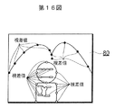
- FIG. 16 shows still another modified example, and is an example of the second viewpoint image 80. In this modification, parallax values representing parallax between feature points and corresponding points are respectively calculated.
- the number is calculated for the corresponding points where the calculated parallax value is in the range of the predetermined parallax value.
- the calculated parallax value is shown in the second viewpoint image 80.
- the parallax value is calculated for each corresponding point by subtracting the abscissa value of the corresponding point in the second viewpoint image corresponding to the feature point from the abscissa value of the feature point in the first viewpoint image.
- the parallax value becomes a plus (+) value or a minus ( ⁇ ) value.
- the disparity value having a negative value is indicated by a black circle and a black thick line.
- a parallax value having a positive value is indicated by a white circle and a white thick line.
- the length of the bold line indicates the magnitude of the parallax value.
- FIGS. 17 to 21 show another embodiment.
- FIG. 17 is a flowchart showing the processing procedure of the digital still camera 1.
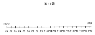
- FIG. 18 shows a position where the focus lens 11 can move.
- FIG. 19 shows 10 m from the second viewpoint image 101 and second viewpoint images 111 to 11 m in which corresponding points are shown.
- the subject is imaged from the second viewpoint at every 20 positions from the NEAR end to the FAR end where the focus lens 11 can be positioned, and 20 second viewpoint images are obtained. Corresponding points are searched from each of the obtained second viewpoint images, and a stereoscopic image is obtained from image data representing the second viewpoint image having the largest number of found corresponding points and image data representing the first viewpoint image. A file is generated.
- the digital still camera 1 is positioned at the first viewpoint and the shutter release button is pressed (first stage and second stage depression) (YES in step 91)
- the subject is imaged from the first viewpoint.
- Step 92 A first viewpoint image is obtained.
- the digital still camera 1 is moved to the position of the second viewpoint (step 93).
- step 94 When the shutter release button is pressed (first step and second step pressed) (YES in step 94), the focus lens 11 moves step by step from the NEAR end to the FAR end within the set range of the focus motor 7. The object is imaged from the second viewpoint for each movement position. A plurality of second viewpoint images having different degrees of focusing are obtained (step 95). For example, assuming that the focus lens 11 can be positioned by the focus motor 7 at 20 positions from the NEAR end to the FAR end from the positions P1 to P20 as shown in FIG. 18, each of these 20 positions. Thus, the focus lens 11 is positioned, and the subject is imaged from the second viewpoint at each position. Twenty second viewpoint images can be obtained. FIG.
- the plurality of second viewpoint images 101 to 10 m have different positions of the focus lens 11 at the time of imaging.
- the position of the focus lens 11 in the second viewpoint image 101 is the NEAR end.
- the position of the focus lens 11 in the second viewpoint image 102 is one FAR side from the NEAR end.
- the position of the focus lens 11 in the second viewpoint image 103 is two FAR sides from the NEAR end.
- the position of the focus lens 11 of the second viewpoint image 10m is the FAR end.
- Feature points are extracted from the first viewpoint image, and corresponding points are searched in each of the obtained second viewpoint images (step 96 in FIG. 17).
- FIG. 19 shows a plurality of second viewpoint images 111 to 11m in which corresponding points found by the search are illustrated.
- the second viewpoint images 101, 102, 103, and 10m respectively correspond to the second viewpoint images 111, 112, 113, and 11m in which corresponding points are illustrated.
- a stereoscopic image file is generated from image data representing the second viewpoint image having the most corresponding points and image data representing the first viewpoint image (17th image).
- Figure step 97 The generated stereoscopic image file is recorded on the memory card 27 (step 98). Since the stereoscopic image file is generated using the second viewpoint image with many corresponding points, an image that is easy to see stereoscopically can be obtained.
- FIG. 20 is a flowchart showing a processing procedure of the digital still camera 1, showing a modification.
- the position of the focus lens 11 is changed, but in this modification, the exposure amount is changed.
- FIG. 20 the same processes as those shown in FIG.
- the exposure correction amount setting range for example, ⁇
- the brightness is changed by 0.3 EV within 3 EV to +3 EV
- the subject is imaged from the second viewpoint for each changed brightness (step 95A).
- a plurality of second viewpoint images are obtained. Corresponding point search processing is performed from each of the obtained second viewpoint images.
- FIG. 21 is a flowchart showing the processing procedure of the digital still camera 1, showing another modification. In the above modification, the exposure amount is changed, but in this modification, the color temperature is changed.
- the same processes as those shown in FIG. As described above, when the digital still camera 1 is moved to the position of the second viewpoint and the shutter release button is pressed (YES in step 93 and step 94), the color temperature setting range (for example, from 2000K) Within 12000K), the color temperature is changed by 500K, and a subject is imaged from the second viewpoint for each changed color temperature (step 95B).
- a plurality of second viewpoint images are obtained. Corresponding point search processing is performed from each of the obtained second viewpoint images.
- a stereoscopic image file is generated from the image data representing the second viewpoint image having the most corresponding points and the image data representing the first viewpoint image (step 97). 22 to 27 show still another embodiment. This embodiment determines the zoom direction (tele side or wide side) of the zoom lens 10 when the second viewpoint image is captured from the feature point according to the direction of the corresponding point when the feature point is used as a reference. The second viewpoint image is picked up with the determined zoom amount in the zoom direction.
- the digital still camera 1 is positioned at the first viewpoint and the shutter release button is pressed (first stage and second stage depression) (YES in step 121), the subject is imaged from the first viewpoint. (Step 122).
- a first viewpoint image is obtained.
- the digital still camera 1 is moved to the position of the second viewpoint (step 123)
- the subject is imaged at the position of the second viewpoint.
- a second viewpoint image is obtained.
- Feature points are extracted from the first viewpoint image, and corresponding points are searched from the second viewpoint image (step 124).
- a global motion indicating the total amount and direction of movement from the first viewpoint image to the second viewpoint image is calculated using the first viewpoint image as a reference (step 125).
- the calculated global motion is removed from the corresponding point of the second viewpoint image, and the direction of the vector of the corresponding point (vector indicating the motion amount and the moving direction of the corresponding point with respect to the feature point) is checked for each corresponding point ( Step 126).
- second viewpoint images 141 and 142 are examples of second viewpoint images 141 and 142 in which the above-described vectors are illustrated.
- the entire image is enlarged as compared with the first viewpoint image, and the vector (indicated by an arrow) indicates outward as a whole.
- the second viewpoint image 142 shown in FIG. 25 the entire image is reduced as compared with the first viewpoint image, and the vector indicates inward as a whole.
- it is determined whether or not the direction of the vector is inward (step 127). If the direction of the vector is inward (YES in step 127), the zoom lens 10 is set to the wide side in order to obtain a second viewpoint image that is magnified compared to the first viewpoint image (step). 128).
- the driving amount of the zoom motor 6 that drives the zoom lens 10 is determined so that the average value of the lengths of the outward vectors is calculated and the calculated average value becomes zero. If the vector direction is not inward (NO in step 127), it is determined whether the vector direction is outward (step 129). If the direction of the vector is outward (YES in step 129), the zoom lens 10 is set to the tele side in order to obtain a second viewpoint image that is reduced as compared with the first viewpoint image (step 129). 130). Similarly to the wide side, the driving amount of the zoom motor 6 that drives the zoom lens 10 is determined so that the average value of the lengths of the inward vectors is calculated and the calculated average value becomes zero.
- step 131 the subject is imaged from the second viewpoint at the set zoom position (step 132).
- a second viewpoint image is obtained.
- a stereoscopic image file is generated from the obtained image data representing the second viewpoint image and image data representing the first viewpoint image (step 133), and the generated stereoscopic image file is recorded in the memory card 27. (Step 134).
- the shift of the angle of view between the first viewpoint image and the second viewpoint image can be reduced.
- step 151 the shutter release button pressed for capturing the second viewpoint image immediately after the digital still camera 1 is moved to the second viewpoint position? It is determined whether or not (step 151).
- the direction of the vector is determined as described above. If the direction of the vector is inward (YES in step 127), the reduction ratio of the second viewpoint image is calculated from the image size of the first viewpoint image and the length of the vector (step 152).
- a zoom amount and a zoom position are determined according to the calculated reduction ratio.
- the zoom lens 10 is set to the wide side so that the determined zoom amount is obtained (step 128).
- the enlargement ratio of the second viewpoint image is calculated from the image size of the first viewpoint image and the length of the vector (step 153).
- a zoom amount and a zoom position are determined according to the calculated enlargement ratio.
- the zoom lens 10 is set to the tele side so that the determined zoom amount is obtained (step 130).
- An image is taken from the second viewpoint at the set zoom position and zoom amount (step 132).
- a stereoscopic image file is generated from the obtained image data representing the first viewpoint image and image data representing the second viewpoint image (step 133), and the generated stereoscopic image file is recorded in the memory card 27. (Step 134). Also in the embodiment or the modified example after FIG.
- the number of corresponding points may be calculated in the same manner as described with reference to FIGS.
- the position of the second viewpoint may be moved little by little to obtain a plurality of second viewpoint images.
- the following control may be performed. First, after the focus lens is positioned and photographed from the first viewpoint, the focus lens position is locked, and after the user moves to the second viewpoint (when the camera stops moving, etc.) ) Shoot the second viewpoint. Then, it may be recorded as the second viewpoint image as it is, or the number of corresponding points in the two viewpoint image is calculated as the initial corresponding point number, and a moving image is taken for a certain time after moving to the second viewpoint.
- the number of corresponding points between each of the second viewpoint images and the first viewpoint image is continuously calculated, and the second viewpoint image having the largest number of corresponding points including the initial number of corresponding points is used as the final second viewpoint image. Record. Furthermore, it goes without saying that the embodiment of the present invention can also be applied to multi-view shooting with three or more viewpoints.
Landscapes
- Engineering & Computer Science (AREA)
- Multimedia (AREA)
- Signal Processing (AREA)
- Physics & Mathematics (AREA)
- General Physics & Mathematics (AREA)
- Testing, Inspecting, Measuring Of Stereoscopic Televisions And Televisions (AREA)
- Studio Devices (AREA)
Abstract
立体画像を構成する画像のうち,対応点の多い画像を見つける。ディジタル・スチル・カメラ1を用いて第1の視点から被写体が撮像され,第1の視点画像が得られる。カメラ1が移動させられて第2の視点から被写体が撮像され,第1回目の第2の視点画像が得られる。さらにフォーカス・レンズの位置が動かされて,第2の視点から被写体が撮像され,第2回目の第2の視点画像が得られる。第1回目の第2の視点画像の中から第1の視点画像の特徴点に対応する対応点の数を示す第1の対応点数が算出される。同様に,第2回目の第2の視点画像から対応点の数を示す第2の対応点数が算出される。第1回目の第2の視点画像と第2回目の第2の視点画像とのうち,対応点数の多い方の第2の視点画像と第1の視点画像とを用いて立体画像が生成される。
Description
この発明は,立体視用画像撮像装置およびその動作制御方法に関する。
立体的な画像を撮像できるカメラが市販されている。立体的な画像を撮像するカメラには,撮像装置が一つのもの,撮像装置が二つのものなどがある。撮像装置が一つのカメラでは,たとえば,カメラを移動させながら得られる多数の画像群(第1の画像群)について隣り合う画像間同士で特徴点の対応付けを行い,特徴点の対応付け情報を用いて第1の画像群の中から視点間隔が一定の画像群(第2の画像群)を得るものがある(特開2006−113807号公報)。第2の画像群によって立体画像が構成される。しかしながら,立体視に適する画像を得ることができないことがある。
この発明は,立体視に適する画像を得ることを目的とする。
第1の発明による立体視用画像撮像装置は,被写体を撮像し,被写体像を表わす画像データを出力する固体電子撮像装置,上記固体電子撮像装置の受光面前方に設けられたフォーカス・レンズ,第1視点において(第1視点用フォーカス・レンズ位置に)上記フォーカス・レンズを位置決めして上記固体電子撮像装置を用いて第1の視点から撮像することにより得られる第1視点画像に含まれる複数の特徴点のそれぞれの対応点を,第2視点において(第2視点用フォーカス・レンズ位置に)上記フォーカス・レンズを位置決めして上記固体電子撮像装置を用いて第2の視点から撮像することにより得られる第2視点画像から探索する対応点探索手段(対応点探索デバイス),第1視点画像に含まれる複数の特徴点のそれぞれの対応点を,上記第2視点におけるフォーカス・レンズ位置からNEAR方向またはFAR方向のいずれか一方の方向に上記フォーカス・レンズを位置決めして上記固体電子撮像装置を用いて第2の視点から撮像することにより得られる第2視点画像から探索するように上記フォーカス・レンズおよび上記対応点探索手段を制御する第1の探索制御手段(第1の探索制御デバイス),上記対応点探索手段により得られた第1の対応点数よりも上記第1の探索制御手段の制御のもとに得られた第2の対応点数の方が多いか少ないかを判断する第1の判断手段(第1の判断デバイス),上記第1の判断手段によって上記対応点探索手段により得られた第1の対応点数よりも上記第1の探索制御手段の制御のもとに得られた第2の対応点数の方が多いと判断されたことに応じて,上記第1の探索制御手段の制御のもとに上記フォーカス・レンズが位置決めされた位置を第2視点におけるフォーカス・レンズ位置(第2視点用フォーカス・レンズ位置)とする第1の更新手段(第1の更新デバイス),および上記第1の更新手段により位置決めされた第2視点におけるフォーカス・レンズ位置(第2視点用フォーカス・レンズ位置)にフォーカス・レンズを位置決めして第2の視点から撮像して得られる画像を表わす画像データと第1視点から撮像して得られた画像データと用いて立体画像ファイルを生成する立体画像ファイル生成手段(立体画像ファイル生成デバイス)を備えていることを特徴とする。
第1の発明は,上記立体視用画像撮像装置に適した動作制御方法も提供している。すなわち,この方法は,被写体を撮像し,被写体像を表わす画像データを出力する固体電子撮像装置,および上記固体電子撮像装置の受光面前方に設けられたフォーカス・レンズを備えた立体視用画像撮像装置の動作制御方法において,対応点探索手段が,第1視点において(第1視点用フォーカス・レンズ位置)上記フォーカス・レンズを位置決めして上記固体電子撮像装置を用いて第1の視点から撮像することにより得られる第1視点画像に含まれる複数の特徴点のそれぞれの対応点を,第2視点において(第2視点用フォーカス・レンズ位置)上記フォーカス・レンズを位置決めして上記固体電子撮像装置を用いて第2の視点から撮像することにより得られる第2視点画像から探索し,第1の探索制御手段が,第1視点画像に含まれる複数の特徴点のそれぞれの対応点を,上記第2視点におけるフォーカス・レンズ位置からNEAR方向またはFAR方向のいずれか一方の方向に上記フォーカス・レンズを位置決めして上記固体電子撮像装置を用いて第2の視点から撮像することにより得られる第2視点画像から探索するように上記フォーカス・レンズおよび上記対応点探索手段を制御し,第1の判断手段が,上記対応点探索手段により得られた第1の対応点数よりも上記第1の探索制御手段の制御のもとに得られた第2の対応点数の方が多いか少ないかを判断し,更新手段が,上記第1の判断手段によって上記対応点探索手段により得られた第1の対応点数よりも上記第1の探索制御手段の制御のもとに得られた第2の対応点数の方が多いと判断されたことに応じて,上記第1の探索制御手段の制御のもとに上記フォーカス・レンズが位置決めされた位置を第2視点におけるフォーカス・レンズ位置とし,立体画像ファイル生成手段が,上記第1の更新手段により位置決めされた第2視点におけるフォーカス・レンズ位置にフォーカス・レンズを位置決めして第2の視点から撮像して得られる画像を表わす画像データと第1視点から撮像して得られた画像データと用いて立体画像ファイルを生成するものである。
第1の発明によると,フォーカス・レンズが第1の視点において(第1視点用フォーカス・レンズ位置。第1視点専用のフォーカス・レンズ位置ではない)位置決めされて固体電子撮像装置を用いて第1の視点から被写体が撮像される。第1の視点画像が得られる。また,フォーカス・レンズが第2視点において{第2視点用フォーカス・レンズ位置。第2視点専用のフォーカス・レンズ位置ではない。第1視点における位置(第1視点用フォーカス・レンズ位置)と同じ位置でも異なる位置でもよいが,処理の最初は第1視点における位置(第1視点用フォーカス・レンズ位置)と同じ位置となろう。}位置決めされて固体電子撮像装置を用いて第2の視点から被写体が撮像される。一つ目の第2視点画像が得られる。さらに,第2視点におけるフォーカス・レンズ位置(第2視点用フォーカス・レンズ位置)からNEAR方向またはFAR方向のいずれか一方の方向の位置にフォーカス・レンズが移動されて固体電子撮像装置を用いて第2の視点から被写体が撮像される。二つ目の第2視点画像が得られる。第1視点画像に含まれる複数の特徴点のそれぞれの対応点が,一つ目の第2視点画像から見つけられる。また,第1視点画像に含まれる複数の特徴点のそれぞれの対応点が,二つ目の第2視点画像から見つけられる。一つ目の第2視点画像から見つけられた対応点の数を表わす第1の対応点数と二つ目の第2視点画像から見つけられた対応点の数を表わす第2の対応点数とが比較される。
一つ目の第2視点画像から見つけられた第1の対応点数よりも二つ目の第2の視点画像から見つけられた第2の対応点数の方が多い場合には,第2視点におけるフォーカス・レンズ位置がNEAR方向またはFAR方向のいずれか一方の方向の位置に更新される。
更新された第2視点におけるフォーカス・レンズ位置(第2視点用フォーカス・レンズ位置)にフォーカス・レンズが位置決めされて第2視点から被写体が撮像される。得られた第2視点画像を表わす画像データと第1の視点画像を表わす画像データとを用いて立体画像ファイルが生成される。
上記第1の判断手段によって上記対応点探索手段により得られた第1の対応点数よりも上記第1の探索制御手段の制御のもとに得られた第2の対応点数の方が少ないと判断されたことに応じて,第1視点画像に含まれる複数の特徴点のそれぞれの対応点を,上記第2視点におけるフォーカス・レンズ位置からNEAR方向またはFAR方向のいずれか他方の方向に上記フォーカス・レンズを位置決めして上記固体電子撮像装置を用いて第2の視点から撮像することにより得られる第2視点画像から探索するように上記フォーカス・レンズおよび上記対応点探索手段を制御する第2の探索制御手段(第2の探索制御デバイス),上記対応点探索手段により得られた第1の対応点数よりも上記第2の探索制御手段の制御のもとに得られた第3の対応点数の方が多いかどうかを判断する第2の判断手段(第2の判断デバイス),および上記第2の判断手段によって上記対応点探索手段により得られた第1の対応点数よりも上記第2の探索制御手段の制御のもとに得られた第3の対応点数の方が多いと判断されたことに応じて,上記第2の探索制御手段の制御のもとに上記フォーカス・レンズが位置決めされた位置を第2視点におけるフォーカス・レンズ位置とする第2の更新手段(第2の更新デバイス)をさらに備えてもよい。この場合,上記立体画像ファイル生成手段は,たとえば,上記第1の更新手段または上記第2の更新手段により位置決めされた第2視点におけるフォーカス・レンズ位置にフォーカス・レンズを位置決めして第2の視点から撮像して得られる画像を表わす画像データと第1視点から撮像して得られた画像データと用いて立体画像ファイルを生成するものとなろう。
上記の処理が繰り返されることにより,第1の視点画像を表わす画像データと,対応点の多い第2の視点画像を表わす画像データとを用いて立体画像ファイルが生成されるようになる。立体視に適した立体画像が得られる。上記対応点探索手段,上記第1の探索制御手段,上記第1の判断手段,上記第1の更新手段,上記第2の探索制御手段,上記第2の判断手段および上記第2の更新手段による各処理を繰り返す制御手段(制御デバイス)をさらに備えてもよい。
上記対応点探索手段において第2の視点から撮像するときの上記フォーカス・レンズの位置を,最初の処理では第1視点におけるフォーカス・レンズ位置とし,その後の処理では上記第2視点におけるフォーカス・レンズ位置とすることが好ましい。
上記対応点探索手段による探索によって見つかった対応点ごとに,特徴点と対応点との視差値を算出する第1の視差値算出手段(第1の視差値算出デバイス),上記第1の探索制御手段による制御のもとに行われる探索によって見つかった対応点ごとに,特徴点と対応点との視差値を算出する第2の視差値算出手段(第2の視差値算出デバイス),上記第2の探索制御手段による制御のもとに行われる探索によって見つかった対応点ごとに,特徴点と対応点との視差値を算出する第3の視差値算出手段(第3の視差値算出デバイス)をさらに備えてもよい。この場合,上記第1の判断手段は,たとえば,上記対応点探索手段により得られた対応点の数のうち上記第1の視差値算出手段によって算出された視差値が所定視差値をもつ対応点の数よりも,上記第1の探索制御手段の制御のもとに得られた対応点の数のうち上記第2の視差値算出手段によって算出された視差値が所定視差値をもつ対応点の数の方が多いか少ないかを判断するものであり,上記第2の判断手段は,たとえば,上記対応点探索手段により得られた対応点の数のうち上記第1の視差値算出手段によって算出された視差値が所定視差値をもつ対応点の数よりも,上記第2の探索制御手段の制御のもとに得られた対応点の数のうち上記第3の視差値算出手段によって算出された視差値が所定視差値をもつ対応点の数の方が多いかどうかを判断するものとなろう。
第2の視点画像から,輝度または色の変化の少ない画像平坦領域を検出する画像平坦領域検出手段(画像平坦領域検出デバイス)をさらに備えてもよい。この場合,上記対応点探索手段による探索,上記第1の探索制御手段の制御のもとに行われる探索および上記第2の探索制御手段の制御のもとに行われる探索を,上記画像平坦領域検出手段によって検出された画像平坦領域を除く第2視点画像の残り画像領域について行うことが好ましい。
上記対応点探索手段による探索,上記第1の探索制御手段の制御のもとに行われる探索および上記第2の探索制御手段の制御のもとに行われる探索を,第2視点画像の左右の端部の所定領域を除く残り画像領域について行うようにしてもよい。
第2の発明による立体視画像撮像装置は,被写体を撮像し,被写体像を表わす画像データを出力する固体電子撮像装置,上記固体電子撮像装置の受光面前方に設けられたフォーカス・レンズ,第1の視点から撮像するように上記固体電子撮像装置を制御する第1の撮像制御手段(第1の撮像制御デバイス),上記フォーカス・レンズの位置を所定距離ずつ移動させながらそれぞれの移動位置で第2の視点から撮像するように上記固体電子撮像装置を制御する第2の撮像制御手段(第2の撮像制御デバイス),上記第1の撮像制御手段の制御のもとに上記固体電子撮像装置から出力される画像データによって表わされる第1視点画像に含まれる複数の特徴点のそれぞれの対応点を,上記第2の撮像制御手段の制御のもとに上記固体電子撮像装置から出力される画像データによって表わされる複数の第2の視点画像のそれぞれから探索する対応点探索手段(対応点探索デバイス),および上記複数の第2の視点画像のうち対応点がもっとも多い第2の視点画像を表わす画像データと上記第1の視点画像を表わす画像データとを用いて立体画像ファイルを生成する立体画像ファイル生成手段(立体画像ファイル生成デバイス)を備えていることを特徴とする。
第2の発明は,上記立体視用画像撮像装置に適した動作制御方法も提供している。すなわち,この方法は,被写体を撮像し,被写体像を表わす画像データを出力する固体電子撮像装置,および上記固体電子撮像装置の受光面前方に設けられたフォーカス・レンズを備えた立体視用画像撮像装置の動作制御方法において,第1の撮像制御手段が,第1の視点から撮像するように上記固体電子撮像装置を制御し,第2の撮像制御手段が,上記フォーカス・レンズの位置を所定距離ずつ移動させながらそれぞれの移動位置で第2の視点から撮像するように上記固体電子撮像装置を制御し,対応点探索手段が,上記第1の撮像制御手段の制御のもとに上記固体電子撮像装置から出力される画像データによって表わされる第1視点画像に含まれる複数の特徴点のそれぞれの対応点を,上記第2の撮像制御手段の制御のもとに上記固体電子撮像装置から出力される画像データによって表わされる複数の第2の視点画像のそれぞれから探索し,立体画像ファイル生成手段が,上記複数の第2の視点画像のうち対応点がもっとも多い第2の視点画像を表わす画像データと上記第1の視点画像を表わす画像データとを用いて立体画像ファイルを生成するものである。
第2の発明によると,まず,固体電子撮像装置を用いて第1の視点から被写体が撮像される。第1視点画像が得られる。つづいて,フォーカス・レンズの位置を所定距離ずつ移動させながら,固体電子撮像装置を用いて第2の視点から被写体が撮像される。複数の第2視点画像が得られる。第1視点画像の複数の特徴点のそれぞれに対応する対応点が,複数の第2視点画像のそれぞれから見つけられる。複数の第2視点画像のうち対応点がもっとも多い第2視点画像を表わす画像データと第1視点画像を表わす画像データとを用いて立体画像ファイルが生成される。対応点の多い第2視点画像を利用して立体画像が得られるので,立体視に適するものとなる。
上記第2の撮像制御手段は,たとえば,上記フォーカス・レンズの位置を,FAR端からNEAR端までの間,所定距離ずつ移動させながらそれぞれの移動位置で第2の視点から撮像するように上記固体電子撮像装置を制御する。
上記対応点探索手段による探索により見つかった対応点ごとに,特徴点と対応点との間の視差値を上記第2の視点画像ごとに算出する視差値算出手段(視差値算出デバイス)をさらに備えてもよい。この場合,上記立体画像ファイル生成手段は,たとえば,上記視差値算出手段によって算出された視差値のうち所定視差値をもつ対応点がもっとも多い第2の視点画像を表わす画像データと上記第1の視点画像を表わす画像データとを用いて立体画像ファイルを生成するものとなろう。
輝度または色の変化の少ない画像平坦領域を検出する画像平坦領域検出手段(画像平坦領域検出デバイス)を備えてもよい。この場合,上記対応点探索手段は,たとえば,上記画像平坦領域検出手段によって検出された画像平坦領域を除く残り画像領域を上記対応点探索の範囲とするものである。
上記対応点探索手段は,第2視点画像の左右の端部の所定領域を除く残り画像領域を上記対応点探索の範囲とするものでもよい。
第3の発明による立体視画像撮像装置は,被写体を撮像し,被写体像を表わす画像データを出力する固体電子撮像装置,上記固体電子撮像装置の受光面前方に設けられたズーム・レンズ,第1の視点から撮像するように上記固体電子撮像装置を制御する第1の撮像制御手段(第1の撮像制御デバイス),第2の視点から撮像するように上記固体電子撮像装置を制御する第2の撮像制御手段(第2の撮像制御デバイス),上記第1の撮像制御手段の制御のもとに上記固体電子撮像装置から出力される画像データによって表わされる第1視点画像に含まれる複数の特徴点のそれぞれの対応点を,上記第2の撮像制御手段の制御のもとに上記固体電子撮像装置から出力される画像データによって表わされる第2の視点画像から探索する対応点探索手段(対応点探索デバイス),上記対応点探索手段によって探索された対応点が,対応する特徴点に対して外側に存在するか内側に存在するかを判断する方向判断手段(方向判断デバイス),上記方向判断手段によって外側に存在すると判断されたことに応じてワイド側に変更し,上記方向判断手段によって内側に存在すると判断されたことに応じてテレ側に変更するように上記ズーム・レンズを制御するズーム・レンズ制御手段(ズーム・レンズ制御デバイス),ならびに第1視点画像を表わす画像データおよび上記ズーム・レンズ制御手段の制御のもとにズーム量が制御されたことに応じて,上記第2の撮像制御手段の制御のもとに上記固体電子撮像装置から出力される第2視点画像を表す画像データを用いて立体画像ファイルを生成する立体画像ファイル生成手段(立体画像ファイル生成デバイス)を備えていることを特徴とする。
第3の発明は,上記立体視用画像撮像装置に適した動作制御方法も提供している。すなわち,この方法は,被写体を撮像し,被写体像を表わす画像データを出力する固体電子撮像装置,および上記固体電子撮像装置の受光面前方に設けられたズーム・レンズを備えた立体視用画像撮像装置の動作制御方法において,第1の撮像制御手段が,第1の視点から撮像するように上記固体電子撮像装置を制御し,第2の撮像制御手段が,第2の視点から撮像するように上記固体電子撮像装置を制御し,対応点探索手段が,上記第1の撮像制御手段の制御のもとに上記固体電子撮像装置から出力される画像データによって表わされる第1視点画像に含まれる複数の特徴点のそれぞれの対応点を,上記第2の撮像制御手段の制御のもとに上記固体電子撮像装置から出力される画像データによって表わされる第2の視点画像から探索し,方向判断手段が,上記対応点探索手段によって探索された対応点が,対応する特徴点に対して外側に存在するか内側に存在するかを判断し,ズーム・レンズ制御手段が,上記方向判断手段によって外側に存在すると判断されたことに応じてワイド側に変更し,上記方向判断手段によって内側に存在すると判断されたことに応じてテレ側に変更するように上記ズーム・レンズを制御し,立体画像ファイル生成手段が,第1視点画像を表わす画像データおよび上記ズーム・レンズ制御手段の制御のもとにズーム量が制御されたことに応じて,上記第2の撮像制御手段の制御のもとに上記固体電子撮像装置から出力される第2視点画像を表す画像データを用いて立体画像ファイルを生成するものである。
第3の発明によると,第1の視点から被写体が撮像されて第1視点画像が得られる。また,第2の視点から被写体が撮像されて第2視点画像が得られる。第1視点画像に含まれる複数の特徴点にそれぞれ対応する対応点が第2視点画像から見つけられる。見つけられた対応点が特徴点に対して外側に存在するか内側に存在するかが判断される。外側に存在すると判断されると,ズーム・レンズがワイド側に変更させられ,内側に存在すると判断されると,ズーム・レンズがテレ側に変更させられる。ズーム量が変更させられた状態で第2の視点から被写体が撮像され,得られた第2視点画像を表わす画像データと第1視点画像を表わす画像データとから立体画像ファイルが生成される。画角のずれていない第1視点画像と第2視点画像とが得られ,立体視に適した立体画像が得られる。
第1の視点画像または第2の視点画像の少なくとも一方の画像の大きさと,対応点と特徴点との拡がりの程度と,にもとづいて,ズーム量を算出するズーム量算出手段(ズーム量算出デバイス)をさらに備えてもよい。この場合,上記ズーム・レンズ制御手段は,たとえば,上記方向判断手段によって外側に存在すると判断されたことに応じて上記ズーム量算出手段によって算出されたズーム量でワイド側に変更し,上記方向判断手段によって内側に存在すると判断されたことに応じて上記ズーム量算出手段によって算出されたズーム量でテレ側に変更するように上記ズーム・レンズを制御するものとなろう。
第1の発明による立体視用画像撮像装置は,被写体を撮像し,被写体像を表わす画像データを出力する固体電子撮像装置,上記固体電子撮像装置の受光面前方に設けられたフォーカス・レンズ,第1視点において(第1視点用フォーカス・レンズ位置に)上記フォーカス・レンズを位置決めして上記固体電子撮像装置を用いて第1の視点から撮像することにより得られる第1視点画像に含まれる複数の特徴点のそれぞれの対応点を,第2視点において(第2視点用フォーカス・レンズ位置に)上記フォーカス・レンズを位置決めして上記固体電子撮像装置を用いて第2の視点から撮像することにより得られる第2視点画像から探索する対応点探索手段(対応点探索デバイス),第1視点画像に含まれる複数の特徴点のそれぞれの対応点を,上記第2視点におけるフォーカス・レンズ位置からNEAR方向またはFAR方向のいずれか一方の方向に上記フォーカス・レンズを位置決めして上記固体電子撮像装置を用いて第2の視点から撮像することにより得られる第2視点画像から探索するように上記フォーカス・レンズおよび上記対応点探索手段を制御する第1の探索制御手段(第1の探索制御デバイス),上記対応点探索手段により得られた第1の対応点数よりも上記第1の探索制御手段の制御のもとに得られた第2の対応点数の方が多いか少ないかを判断する第1の判断手段(第1の判断デバイス),上記第1の判断手段によって上記対応点探索手段により得られた第1の対応点数よりも上記第1の探索制御手段の制御のもとに得られた第2の対応点数の方が多いと判断されたことに応じて,上記第1の探索制御手段の制御のもとに上記フォーカス・レンズが位置決めされた位置を第2視点におけるフォーカス・レンズ位置(第2視点用フォーカス・レンズ位置)とする第1の更新手段(第1の更新デバイス),および上記第1の更新手段により位置決めされた第2視点におけるフォーカス・レンズ位置(第2視点用フォーカス・レンズ位置)にフォーカス・レンズを位置決めして第2の視点から撮像して得られる画像を表わす画像データと第1視点から撮像して得られた画像データと用いて立体画像ファイルを生成する立体画像ファイル生成手段(立体画像ファイル生成デバイス)を備えていることを特徴とする。
第1の発明は,上記立体視用画像撮像装置に適した動作制御方法も提供している。すなわち,この方法は,被写体を撮像し,被写体像を表わす画像データを出力する固体電子撮像装置,および上記固体電子撮像装置の受光面前方に設けられたフォーカス・レンズを備えた立体視用画像撮像装置の動作制御方法において,対応点探索手段が,第1視点において(第1視点用フォーカス・レンズ位置)上記フォーカス・レンズを位置決めして上記固体電子撮像装置を用いて第1の視点から撮像することにより得られる第1視点画像に含まれる複数の特徴点のそれぞれの対応点を,第2視点において(第2視点用フォーカス・レンズ位置)上記フォーカス・レンズを位置決めして上記固体電子撮像装置を用いて第2の視点から撮像することにより得られる第2視点画像から探索し,第1の探索制御手段が,第1視点画像に含まれる複数の特徴点のそれぞれの対応点を,上記第2視点におけるフォーカス・レンズ位置からNEAR方向またはFAR方向のいずれか一方の方向に上記フォーカス・レンズを位置決めして上記固体電子撮像装置を用いて第2の視点から撮像することにより得られる第2視点画像から探索するように上記フォーカス・レンズおよび上記対応点探索手段を制御し,第1の判断手段が,上記対応点探索手段により得られた第1の対応点数よりも上記第1の探索制御手段の制御のもとに得られた第2の対応点数の方が多いか少ないかを判断し,更新手段が,上記第1の判断手段によって上記対応点探索手段により得られた第1の対応点数よりも上記第1の探索制御手段の制御のもとに得られた第2の対応点数の方が多いと判断されたことに応じて,上記第1の探索制御手段の制御のもとに上記フォーカス・レンズが位置決めされた位置を第2視点におけるフォーカス・レンズ位置とし,立体画像ファイル生成手段が,上記第1の更新手段により位置決めされた第2視点におけるフォーカス・レンズ位置にフォーカス・レンズを位置決めして第2の視点から撮像して得られる画像を表わす画像データと第1視点から撮像して得られた画像データと用いて立体画像ファイルを生成するものである。
第1の発明によると,フォーカス・レンズが第1の視点において(第1視点用フォーカス・レンズ位置。第1視点専用のフォーカス・レンズ位置ではない)位置決めされて固体電子撮像装置を用いて第1の視点から被写体が撮像される。第1の視点画像が得られる。また,フォーカス・レンズが第2視点において{第2視点用フォーカス・レンズ位置。第2視点専用のフォーカス・レンズ位置ではない。第1視点における位置(第1視点用フォーカス・レンズ位置)と同じ位置でも異なる位置でもよいが,処理の最初は第1視点における位置(第1視点用フォーカス・レンズ位置)と同じ位置となろう。}位置決めされて固体電子撮像装置を用いて第2の視点から被写体が撮像される。一つ目の第2視点画像が得られる。さらに,第2視点におけるフォーカス・レンズ位置(第2視点用フォーカス・レンズ位置)からNEAR方向またはFAR方向のいずれか一方の方向の位置にフォーカス・レンズが移動されて固体電子撮像装置を用いて第2の視点から被写体が撮像される。二つ目の第2視点画像が得られる。第1視点画像に含まれる複数の特徴点のそれぞれの対応点が,一つ目の第2視点画像から見つけられる。また,第1視点画像に含まれる複数の特徴点のそれぞれの対応点が,二つ目の第2視点画像から見つけられる。一つ目の第2視点画像から見つけられた対応点の数を表わす第1の対応点数と二つ目の第2視点画像から見つけられた対応点の数を表わす第2の対応点数とが比較される。
一つ目の第2視点画像から見つけられた第1の対応点数よりも二つ目の第2の視点画像から見つけられた第2の対応点数の方が多い場合には,第2視点におけるフォーカス・レンズ位置がNEAR方向またはFAR方向のいずれか一方の方向の位置に更新される。
更新された第2視点におけるフォーカス・レンズ位置(第2視点用フォーカス・レンズ位置)にフォーカス・レンズが位置決めされて第2視点から被写体が撮像される。得られた第2視点画像を表わす画像データと第1の視点画像を表わす画像データとを用いて立体画像ファイルが生成される。
上記第1の判断手段によって上記対応点探索手段により得られた第1の対応点数よりも上記第1の探索制御手段の制御のもとに得られた第2の対応点数の方が少ないと判断されたことに応じて,第1視点画像に含まれる複数の特徴点のそれぞれの対応点を,上記第2視点におけるフォーカス・レンズ位置からNEAR方向またはFAR方向のいずれか他方の方向に上記フォーカス・レンズを位置決めして上記固体電子撮像装置を用いて第2の視点から撮像することにより得られる第2視点画像から探索するように上記フォーカス・レンズおよび上記対応点探索手段を制御する第2の探索制御手段(第2の探索制御デバイス),上記対応点探索手段により得られた第1の対応点数よりも上記第2の探索制御手段の制御のもとに得られた第3の対応点数の方が多いかどうかを判断する第2の判断手段(第2の判断デバイス),および上記第2の判断手段によって上記対応点探索手段により得られた第1の対応点数よりも上記第2の探索制御手段の制御のもとに得られた第3の対応点数の方が多いと判断されたことに応じて,上記第2の探索制御手段の制御のもとに上記フォーカス・レンズが位置決めされた位置を第2視点におけるフォーカス・レンズ位置とする第2の更新手段(第2の更新デバイス)をさらに備えてもよい。この場合,上記立体画像ファイル生成手段は,たとえば,上記第1の更新手段または上記第2の更新手段により位置決めされた第2視点におけるフォーカス・レンズ位置にフォーカス・レンズを位置決めして第2の視点から撮像して得られる画像を表わす画像データと第1視点から撮像して得られた画像データと用いて立体画像ファイルを生成するものとなろう。
上記の処理が繰り返されることにより,第1の視点画像を表わす画像データと,対応点の多い第2の視点画像を表わす画像データとを用いて立体画像ファイルが生成されるようになる。立体視に適した立体画像が得られる。上記対応点探索手段,上記第1の探索制御手段,上記第1の判断手段,上記第1の更新手段,上記第2の探索制御手段,上記第2の判断手段および上記第2の更新手段による各処理を繰り返す制御手段(制御デバイス)をさらに備えてもよい。
上記対応点探索手段において第2の視点から撮像するときの上記フォーカス・レンズの位置を,最初の処理では第1視点におけるフォーカス・レンズ位置とし,その後の処理では上記第2視点におけるフォーカス・レンズ位置とすることが好ましい。
上記対応点探索手段による探索によって見つかった対応点ごとに,特徴点と対応点との視差値を算出する第1の視差値算出手段(第1の視差値算出デバイス),上記第1の探索制御手段による制御のもとに行われる探索によって見つかった対応点ごとに,特徴点と対応点との視差値を算出する第2の視差値算出手段(第2の視差値算出デバイス),上記第2の探索制御手段による制御のもとに行われる探索によって見つかった対応点ごとに,特徴点と対応点との視差値を算出する第3の視差値算出手段(第3の視差値算出デバイス)をさらに備えてもよい。この場合,上記第1の判断手段は,たとえば,上記対応点探索手段により得られた対応点の数のうち上記第1の視差値算出手段によって算出された視差値が所定視差値をもつ対応点の数よりも,上記第1の探索制御手段の制御のもとに得られた対応点の数のうち上記第2の視差値算出手段によって算出された視差値が所定視差値をもつ対応点の数の方が多いか少ないかを判断するものであり,上記第2の判断手段は,たとえば,上記対応点探索手段により得られた対応点の数のうち上記第1の視差値算出手段によって算出された視差値が所定視差値をもつ対応点の数よりも,上記第2の探索制御手段の制御のもとに得られた対応点の数のうち上記第3の視差値算出手段によって算出された視差値が所定視差値をもつ対応点の数の方が多いかどうかを判断するものとなろう。
第2の視点画像から,輝度または色の変化の少ない画像平坦領域を検出する画像平坦領域検出手段(画像平坦領域検出デバイス)をさらに備えてもよい。この場合,上記対応点探索手段による探索,上記第1の探索制御手段の制御のもとに行われる探索および上記第2の探索制御手段の制御のもとに行われる探索を,上記画像平坦領域検出手段によって検出された画像平坦領域を除く第2視点画像の残り画像領域について行うことが好ましい。
上記対応点探索手段による探索,上記第1の探索制御手段の制御のもとに行われる探索および上記第2の探索制御手段の制御のもとに行われる探索を,第2視点画像の左右の端部の所定領域を除く残り画像領域について行うようにしてもよい。
第2の発明による立体視画像撮像装置は,被写体を撮像し,被写体像を表わす画像データを出力する固体電子撮像装置,上記固体電子撮像装置の受光面前方に設けられたフォーカス・レンズ,第1の視点から撮像するように上記固体電子撮像装置を制御する第1の撮像制御手段(第1の撮像制御デバイス),上記フォーカス・レンズの位置を所定距離ずつ移動させながらそれぞれの移動位置で第2の視点から撮像するように上記固体電子撮像装置を制御する第2の撮像制御手段(第2の撮像制御デバイス),上記第1の撮像制御手段の制御のもとに上記固体電子撮像装置から出力される画像データによって表わされる第1視点画像に含まれる複数の特徴点のそれぞれの対応点を,上記第2の撮像制御手段の制御のもとに上記固体電子撮像装置から出力される画像データによって表わされる複数の第2の視点画像のそれぞれから探索する対応点探索手段(対応点探索デバイス),および上記複数の第2の視点画像のうち対応点がもっとも多い第2の視点画像を表わす画像データと上記第1の視点画像を表わす画像データとを用いて立体画像ファイルを生成する立体画像ファイル生成手段(立体画像ファイル生成デバイス)を備えていることを特徴とする。
第2の発明は,上記立体視用画像撮像装置に適した動作制御方法も提供している。すなわち,この方法は,被写体を撮像し,被写体像を表わす画像データを出力する固体電子撮像装置,および上記固体電子撮像装置の受光面前方に設けられたフォーカス・レンズを備えた立体視用画像撮像装置の動作制御方法において,第1の撮像制御手段が,第1の視点から撮像するように上記固体電子撮像装置を制御し,第2の撮像制御手段が,上記フォーカス・レンズの位置を所定距離ずつ移動させながらそれぞれの移動位置で第2の視点から撮像するように上記固体電子撮像装置を制御し,対応点探索手段が,上記第1の撮像制御手段の制御のもとに上記固体電子撮像装置から出力される画像データによって表わされる第1視点画像に含まれる複数の特徴点のそれぞれの対応点を,上記第2の撮像制御手段の制御のもとに上記固体電子撮像装置から出力される画像データによって表わされる複数の第2の視点画像のそれぞれから探索し,立体画像ファイル生成手段が,上記複数の第2の視点画像のうち対応点がもっとも多い第2の視点画像を表わす画像データと上記第1の視点画像を表わす画像データとを用いて立体画像ファイルを生成するものである。
第2の発明によると,まず,固体電子撮像装置を用いて第1の視点から被写体が撮像される。第1視点画像が得られる。つづいて,フォーカス・レンズの位置を所定距離ずつ移動させながら,固体電子撮像装置を用いて第2の視点から被写体が撮像される。複数の第2視点画像が得られる。第1視点画像の複数の特徴点のそれぞれに対応する対応点が,複数の第2視点画像のそれぞれから見つけられる。複数の第2視点画像のうち対応点がもっとも多い第2視点画像を表わす画像データと第1視点画像を表わす画像データとを用いて立体画像ファイルが生成される。対応点の多い第2視点画像を利用して立体画像が得られるので,立体視に適するものとなる。
上記第2の撮像制御手段は,たとえば,上記フォーカス・レンズの位置を,FAR端からNEAR端までの間,所定距離ずつ移動させながらそれぞれの移動位置で第2の視点から撮像するように上記固体電子撮像装置を制御する。
上記対応点探索手段による探索により見つかった対応点ごとに,特徴点と対応点との間の視差値を上記第2の視点画像ごとに算出する視差値算出手段(視差値算出デバイス)をさらに備えてもよい。この場合,上記立体画像ファイル生成手段は,たとえば,上記視差値算出手段によって算出された視差値のうち所定視差値をもつ対応点がもっとも多い第2の視点画像を表わす画像データと上記第1の視点画像を表わす画像データとを用いて立体画像ファイルを生成するものとなろう。
輝度または色の変化の少ない画像平坦領域を検出する画像平坦領域検出手段(画像平坦領域検出デバイス)を備えてもよい。この場合,上記対応点探索手段は,たとえば,上記画像平坦領域検出手段によって検出された画像平坦領域を除く残り画像領域を上記対応点探索の範囲とするものである。
上記対応点探索手段は,第2視点画像の左右の端部の所定領域を除く残り画像領域を上記対応点探索の範囲とするものでもよい。
第3の発明による立体視画像撮像装置は,被写体を撮像し,被写体像を表わす画像データを出力する固体電子撮像装置,上記固体電子撮像装置の受光面前方に設けられたズーム・レンズ,第1の視点から撮像するように上記固体電子撮像装置を制御する第1の撮像制御手段(第1の撮像制御デバイス),第2の視点から撮像するように上記固体電子撮像装置を制御する第2の撮像制御手段(第2の撮像制御デバイス),上記第1の撮像制御手段の制御のもとに上記固体電子撮像装置から出力される画像データによって表わされる第1視点画像に含まれる複数の特徴点のそれぞれの対応点を,上記第2の撮像制御手段の制御のもとに上記固体電子撮像装置から出力される画像データによって表わされる第2の視点画像から探索する対応点探索手段(対応点探索デバイス),上記対応点探索手段によって探索された対応点が,対応する特徴点に対して外側に存在するか内側に存在するかを判断する方向判断手段(方向判断デバイス),上記方向判断手段によって外側に存在すると判断されたことに応じてワイド側に変更し,上記方向判断手段によって内側に存在すると判断されたことに応じてテレ側に変更するように上記ズーム・レンズを制御するズーム・レンズ制御手段(ズーム・レンズ制御デバイス),ならびに第1視点画像を表わす画像データおよび上記ズーム・レンズ制御手段の制御のもとにズーム量が制御されたことに応じて,上記第2の撮像制御手段の制御のもとに上記固体電子撮像装置から出力される第2視点画像を表す画像データを用いて立体画像ファイルを生成する立体画像ファイル生成手段(立体画像ファイル生成デバイス)を備えていることを特徴とする。
第3の発明は,上記立体視用画像撮像装置に適した動作制御方法も提供している。すなわち,この方法は,被写体を撮像し,被写体像を表わす画像データを出力する固体電子撮像装置,および上記固体電子撮像装置の受光面前方に設けられたズーム・レンズを備えた立体視用画像撮像装置の動作制御方法において,第1の撮像制御手段が,第1の視点から撮像するように上記固体電子撮像装置を制御し,第2の撮像制御手段が,第2の視点から撮像するように上記固体電子撮像装置を制御し,対応点探索手段が,上記第1の撮像制御手段の制御のもとに上記固体電子撮像装置から出力される画像データによって表わされる第1視点画像に含まれる複数の特徴点のそれぞれの対応点を,上記第2の撮像制御手段の制御のもとに上記固体電子撮像装置から出力される画像データによって表わされる第2の視点画像から探索し,方向判断手段が,上記対応点探索手段によって探索された対応点が,対応する特徴点に対して外側に存在するか内側に存在するかを判断し,ズーム・レンズ制御手段が,上記方向判断手段によって外側に存在すると判断されたことに応じてワイド側に変更し,上記方向判断手段によって内側に存在すると判断されたことに応じてテレ側に変更するように上記ズーム・レンズを制御し,立体画像ファイル生成手段が,第1視点画像を表わす画像データおよび上記ズーム・レンズ制御手段の制御のもとにズーム量が制御されたことに応じて,上記第2の撮像制御手段の制御のもとに上記固体電子撮像装置から出力される第2視点画像を表す画像データを用いて立体画像ファイルを生成するものである。
第3の発明によると,第1の視点から被写体が撮像されて第1視点画像が得られる。また,第2の視点から被写体が撮像されて第2視点画像が得られる。第1視点画像に含まれる複数の特徴点にそれぞれ対応する対応点が第2視点画像から見つけられる。見つけられた対応点が特徴点に対して外側に存在するか内側に存在するかが判断される。外側に存在すると判断されると,ズーム・レンズがワイド側に変更させられ,内側に存在すると判断されると,ズーム・レンズがテレ側に変更させられる。ズーム量が変更させられた状態で第2の視点から被写体が撮像され,得られた第2視点画像を表わす画像データと第1視点画像を表わす画像データとから立体画像ファイルが生成される。画角のずれていない第1視点画像と第2視点画像とが得られ,立体視に適した立体画像が得られる。
第1の視点画像または第2の視点画像の少なくとも一方の画像の大きさと,対応点と特徴点との拡がりの程度と,にもとづいて,ズーム量を算出するズーム量算出手段(ズーム量算出デバイス)をさらに備えてもよい。この場合,上記ズーム・レンズ制御手段は,たとえば,上記方向判断手段によって外側に存在すると判断されたことに応じて上記ズーム量算出手段によって算出されたズーム量でワイド側に変更し,上記方向判断手段によって内側に存在すると判断されたことに応じて上記ズーム量算出手段によって算出されたズーム量でテレ側に変更するように上記ズーム・レンズを制御するものとなろう。
第1図はディジタル・スチル・カメラを用いて立体撮像モードで撮像する様子を示す。
第2図はディジタル・スチル・カメラの電気的構成を示すブロック図である。
第3図および第4図はディジタル・スチル・カメラの処理手順を示すフローチャートである。
第5図はフォーカス・レンズの位置を示している。
第6図は第1の視点画像の一例である。
第7a図,第7b図,第8a図,第8b図,第9a図および第9b図は第2の視点画像の一例である。
第10図から第13図はディジタル・スチル・カメラの処理手順を示すフローチャートである。
第14図から第16図は第2の視点画像の一例である。
第17図はディジタル・スチル・カメラの処理手順を示すフローチャートである。
第18図はフォーカス・レンズ位置を示している。
第19図は第2の視点画像の一例である。
第20図から第23図はディジタル・スチル・カメラの処理手順を示すフローチャートである。
第24図および第25図は第2の視点画像の一例である。
第26図および第27図はディジタル・スチル・カメラの処理手順を示すフローチャートである。
第2図はディジタル・スチル・カメラの電気的構成を示すブロック図である。
第3図および第4図はディジタル・スチル・カメラの処理手順を示すフローチャートである。
第5図はフォーカス・レンズの位置を示している。
第6図は第1の視点画像の一例である。
第7a図,第7b図,第8a図,第8b図,第9a図および第9b図は第2の視点画像の一例である。
第10図から第13図はディジタル・スチル・カメラの処理手順を示すフローチャートである。
第14図から第16図は第2の視点画像の一例である。
第17図はディジタル・スチル・カメラの処理手順を示すフローチャートである。
第18図はフォーカス・レンズ位置を示している。
第19図は第2の視点画像の一例である。
第20図から第23図はディジタル・スチル・カメラの処理手順を示すフローチャートである。
第24図および第25図は第2の視点画像の一例である。
第26図および第27図はディジタル・スチル・カメラの処理手順を示すフローチャートである。
第1図は,この発明の実施例を示すもので,被写体を撮像するときのディジタル・スチル・カメラ1(ディジタル・スチル・カメラだけでなく,ムービ・ディジタル・カメラ,スチル撮像の機能とムービ撮像機能との両方の機能を有するディジタル・カメラにも適用できる。)の位置関係を示している。
この実施例によるディジタル・スチル・カメラ1は,同一の被写体を複数回撮像することによって得られる画像から,立体視可能な画像(以下,立体画像という)を得るものである。立体画像を得るために,ディジタル・スチル・カメラ1はその位置(視点)が移動させられ,移動の前後のそれぞれにおいて視点を異ならせて被写体が撮像される。第1図はユーザがディジタル・スチル・カメラ1を用いて左目用視点(基準視点)から1回目の撮像を行い,その後被写体に向かって右方向に移動して右目用視点から2回目の撮像を行うときのディジタル・スチル・カメラ1の位置関係を示している。以下の説明では,移動前の撮像によって得られる画像を「左目用画像」(第1の視点画像)とし,水平方向に移動後の撮像によって得られる画像を「右目用画像」(第2の視点画像)とする。もちろん,移動前の撮像によって得られる画像を「右目用画像」とし,移動後の撮像によって得られる画像を「左目用画像」としてもよい。この場合には,ユーザ(ディジタル・スチル・カメラ1)の移動方向は被写体に向かって左方向となる。いずれにしても左目用画像および右目用画像の2つの画像から立体画像が構成される。
第2図はディジタル・スチル・カメラ1の電気的構成を示すブロック図である。
ディジタル・スチル・カメラ1の全体的な動作はCPU2によって統括される。
ディジタル・スチル・カメラ1は固体電子撮像素子(CCD,CMOSなど)15を備え,固体電子撮像素子15の前方にズーム・レンズ10,撮像レンズ11,絞り12,赤外線カット・フィルタ13および光学的ロウ・パス・フィルタ(OLPF)14が設けられている。ズーム・レンズ10,フォーカス・レンズ11,絞り12および固体電子撮像素子15は,それぞれズーム・モータ6,フォーカス・モータ7,絞り駆動回路8および撮像素子駆動回路9によって制御される。
ディジタル・スチル・カメラ1は操作器3を備えている。操作器3には電源ボタン,モード設定ダイアル,二段ストローク・タイプのシャッタ・レリーズ・ボタンなどが含まれる。操作器3から出力される操作信号はCPU2に入力する。モード設定ダイアルによって設定されるモードには撮像モード,再生モードなどがある。撮像モードの中にはさらに通常撮像モード,立体撮像モードなどがある。
またディジタル・スチル・カメラ1には,ストロボ撮像のための発光装置4および発光装置4から出射される出射光の反射光を受光するための受光装置5が設けられている。
ディジタル・スチル・カメラ1の電源がオンされ,撮像モードが設定されると,被写体像を表す光線束が,撮像レンズ11,絞り12,赤外線カット・フィルタ13および光学的ロウ・パス・フィルタ14を介して固体電子撮像素子15の受光面に入射する。固体電子撮像素子15の受光面上に被写体像が結像し,被写体像を表すアナログ映像信号が固体電子撮像素子15から出力する。固体電子撮像素子15によって一定周期で被写体が撮像され,一定周期で被写体像を表すアナログ映像信号が1フレーム分ずつ出力される。
固体電子撮像素子15から出力された被写体像を表すアナログ映像信号はアナログ信号処理装置16に入力する。アナログ信号処理装置16は相関二重サンプリング回路,信号増幅器などを含み,ここで相関二重サンプリング,信号増幅などが行われる。アナログ信号処理装置16から出力されたアナログ映像信号はアナログ/ディジタル変換回路17に入力し,ここでディジタル画像データに変換される。ディジタル画像データはデータ・バス32を介してメモリ制御回路21に与えられる。メモリ制御回路21の制御のもと,ディジタル画像データはメイン・メモリ22に一時的に記録される。メモリ制御回路21等は,CPU2と制御線31によって接続されている。
ディジタル画像データはメイン・メモリ22から読出され,データ・バス31または32を介してディジタル信号処理回路23に入力する。ディジタル信号処理回路23では白バランス調整,ガンマ補正などの所定のディジタル信号処理が行われる。ディジタル信号処理回路23においてディジタル信号処理が行われたデータは表示制御回路28に与えられる。表示制御回路28によって表示装置29が制御されることにより表示画面上に被写体像が表示される。
シャッタ・レリーズ・ボタンの第一段階の押下があると,フォーカス・モータ7によってレンズ11が駆動されて焦点合わせが行われる。メイン・メモリ22から読出される画像データに基づいてディジタル信号処理回路23において輝度データが得られ,輝度データは積算回路25に入力して積算される。積算値を表すデータはCPU2に与えられて露出量が算出される。算出された露出量となるように絞り12の開口が絞り駆動回路8によって制御され,固体電子撮像素子15のシャッタ速度が撮像素子駆動回路9によって制御される。
シャッタ・レリーズ・ボタンの第二段階の押下があると,上述のように撮像されてアナログ/ディジタル変換回路17から出力された画像データはメイン・メモリ22に記録される。メイン・メモリ22から読み出された画像データに対し,上述のようにディジタル信号処理回路23において所定のディジタル信号処理が行われる。ディジタル信号処理回路23から出力された画像データは圧縮伸張処理回路24においてデータ圧縮される。圧縮された画像データが外部メモリ制御回路26の制御によってメモリ・カード27に記録される。
操作器3において再生モードが設定されると,メモリ・カード27に記録されている圧縮画像データが読出される。読出された圧縮画像データは圧縮伸張処理回路24において伸張された後,表示制御回路28に与えられる。表示装置29の表示画面上に再生画像が表示される。
上述したように,ディジタル・スチル・カメラ1は立体画像を得ることができる。立体画像を得る場合には,操作器3のモード選択ダイアルが用いられて立体撮像モードが選択される。
第3図および第4図は,立体撮像モードが選択された場合のディジタル・スチル・カメラ1の処理手順を示すフローチャートである。
この実施例では,第1の視点(左目用画像を撮像する左目視点)から撮像が行われて第1視点画像(左目用画像)が得られる。その後,ディジタル・スチル・カメラ1が水平方向に移動させられて,第2の視点(右目用画像を撮像する右目視点)から複数回の撮像が行われて複数の第2視点画像(右目用画像)が得られる。複数の第2視点画像が得られる撮像においては,フォーカス・レンズ11の位置が撮像ごとに変えられる。第1視点画像から特徴を表わす特徴点が見つけられ,複数の第2視点画像のそれぞれにおいて,特徴点に対応する対応点が見つけられる。フォーカス・レンズ11の位置が変えられて得られた複数の第2視点画像のうち,対応点の数が多い第2視点画像を表わす画像データと第1視点画像を表わす画像データとから立体画像ファイルが生成されてメモリ・カード27に記録される。
立体撮像モードが設定されると,まず,ディジタル・スチル・カメラ1が第1視点の位置に位置決めされる。シャッタ・レリーズ・ボタンの第1段階の押し下げおよび第2段階の押し下げがあると(ステップ30でYES),上述のように第1段階の押し下げに応じて焦点合わせが行われてフォーカス・レンズ11が位置決め(第1のフォーカス・レンズ位置)される。2段ストローク・タイプのシャッタ・レリーズ・ボタンでなくともよい。
第5図は,フォーカス・レンズ11の位置を示している。第1のフォーカス・レンズ(第1視点におけるフォーカス・レンズ位置,第1視点用フォーカス・レンズ位置)位置は,たとえば,位置F0であるとする。その位置F0にフォーカス・レンズ11が位置決めされて第1視点からの撮像が行われる。
上述のように,第1のフォーカス・レンズ位置F0にフォーカス・レンズ11が位置決めされて第1の視点から被写体が撮像されると(第3図ステップ31),第1視点画像が得られる。
第6図は第1視点画像51の一例である。第1視点画像51は,立体視するときに観賞者が左目で見る左目用画像である。もっとも,上述したように,第1視点画像51が右目で見る右目用画像であってもよいのはいうまでもない。第1視点画像51が右目用画像の場合には,第1視点から第2視点にはディジタル・スチル・カメラ1は被写体に向かって左側に移動することとなり,後述する第2視点画像が左目用画像となる。
第3図に戻って,第1視点からの撮像が終わるとユーザ(カメラマン)によってディジタル・スチル・カメラ1が第1の視点から第2の視点に動かされる(ステップ32)。
ディジタル・スチル・カメラ1が第2の視点に動かされると,第1の視点画像51が撮像された第2のフォーカス・レンズ位置(第1のフォーカス・レンズ位置と異なる位置でもよいし,第1のフォーカス・レンズ位置と同じでもよいが,好ましくは第1のフォーカス・レンズ位置と同じとなろう。第2視点用フォーカス・レンズ位置。)で第2の視点から被写体が撮像される(ステップ33)。フォーカス・レンズ11が第5図に示す位置F0で第2の視点から被写体が撮像される。これにより,第7a図に示すように第1回目の第2視点画像52が得られる。第2視点画像52は,第1視点画像51を撮像したときのフォーカス・レンズ11の位置(第1のフォーカス・レンズ位置)と同じ位置(異なる位置でもよい)にフォーカス・レンズ11が位置決めされて撮像されたものである。
つづいて,第6図に示す第1視点画像51から特徴点が抽出される(第3図ステップ34)。第1視点画像51を表わす画像データは,メイン・メモリ22に記憶されており,メイン・メモリ22から読み出されて特徴点が抽出される。画像中の物体の角や線分の交点等が検出されて特徴点(特徴画素)とされる(第6図において特徴点は図示が省略されている)。第1視点画像51から見つけられた特徴点に対応する対応点が探索され第2視点画像52から見つけられる(ステップ34)。第2視点画像52を表わす画像データも上述のようにメイン・メモリ22に記憶されており,メイン・メモリ22から読み出されて対応点が抽出される。対応点は,特徴点と相関の高い画素である。対応点探索処理はテンプレートマッチング等によって局所的に行われ,複数回の対応点探索処理によって画像全体に対する処理が実行される。
第7b図は,対応点探索処理により見つけられた対応点が示されている(一部のみが図示されている)第1回目の第2の視点画像52の一例である。第1回目の第2の視点画像52から対応点が見つけられると,見つけられた対応点の数PR1(第1の対応点数)が算出される(第3図ステップ34)。
第2のフォーカス・レンズ位置(最初は第1のフォーカス・レンズ位置と同じであり,第5図の位置F0)に位置決めされているフォーカス・レンズ11がNEAR側に一つ移動させられる(第5図の位置F1の位置)(ステップ35)。
フォーカス・レンズ11の移動後の位置で第2の視点から被写体が撮像される(ステップ36)。これにより,第8a図に示すように第2回目の第2視点画像53が得られる。すると,第2回目の第2視点画像53から対応点が見つけられ,その対応点の数である第2対応点数PR2が算出される(ステップ37)。第8b図は,見つけられた対応点が(一部)図示されている第2回目の第2視点画像53の一例である。
つづいて,第7b図で示すように第1回目の第2視点画像52から見つけられた第1の対応点数PR1よりも,第8b図で示すように第2回目の第2視点画像53から見つけられた第2の対応点数PR2の方が多いか少ないかが判定される(第4図ステップ38)。
第1の対応点数PR1よりも第2の対応点数PR2の方が多いと(第4図ステップ38でYES),フォーカス・レンズ11がNEAR側に移動させた方が第1の視点画像に対応が取れている第2の視点画像を撮像できるということである。このために,現在のフォーカス・レンズ11の位置が,第2の視点画像を撮像するためのフォーカス位置である第2のフォーカス位置とされる(第4図ステップ39)(この場合,第2のフォーカス・レンズ位置は,第5図の位置F1となる)。シャッタ・レリーズ・ボタンが押されると(第4図ステップ46でYES),第2のフォーカス・レンズ位置で第2の視点から被写体が撮像される(第4図ステップ47)。通常はシャッタ・レリーズ・ボタンの第1段階の押し下げによりフォーカシング処理が行われてフォーカス・レンズ11が移動させられるが,この実施例ではフォーカス・レンズ11は第2のフォーカス・レンズ位置に位置決めされる。撮像によって得られた第2視点画像を表わす画像データと第1視点画像を表わす画像データとから立体画像ファイルが生成される(第4図ステップ47)。生成された立体画像ファイルがメモリ・カード27に記録される(第4図ステップ48)。シャッタ・レリーズ・ボタンが押されなければ(第4図ステップ46でNO),第3図ステップ33からの処理が繰り返される。
第1の対応点数PR1よりも第2の対応点数PR2の方が多くなければ(少なければ)(第4図ステップ38でNO),フォーカス・レンズ11をNEAR側に移動させない方が第1の視点画像との対応がとれているということである。このために,フォーカス・レンズ11が現在の第2のフォーカス・レンズ位置(第5図の位置F0)から一つFAR側(第5図の位置F(−1))に移動させられる(第4図ステップ40)。フォーカス・レンズ11が一つFAR側に移動させられた状態で,第2の視点から被写体が撮像される(第4図ステップ41)。第9a図に示す第3回目の第2視点画像54が得られる。得られた第3回目の第2視点画像54から対応点が探索されて,第9b図に示すように対応点が得られる。得られた対応点の数を示す第3の対応点数PR3が算出される(第4図ステップ42)。
第1の対応点数PR1よりも第3の対応点数PR3の方が多ければ(ステップ43でYES),フォーカス・レンズ11をFAR側に移動させたときに得られる第2の視点画像の方が移動前に得られる第2の視点画像のよりも第1の視点画像との対応が取れている。このために,現在のフォーカス・レンズ位置(第5図の位置F(−1))が第2のフォーカス・レンズ位置とされる(第4図ステップ44)。第1の対応点数PR1よりも第3の対応点数PR3の方が多くなければ(第4図ステップ43でNO),フォーカス・レンズ11が現在のフォーカス・レンズ位置(第5図の位置F(−1))からNEAR側に一つ戻して(第5図の位置F0),第2のフォーカス・レンズ位置とされる(ステップ45)。
シャッタ・レリーズ・ボタンが押されると(第4図ステップ46でYES),第2のフォーカス・レンズ位置で第2の視点から被写体が撮像される(第4図ステップ47)。撮像によって得られた第2視点画像を表わす画像データと第1視点画像を表わす画像データとから立体画像ファイルが生成される(第4図ステップ48)。生成された立体画像ファイルがメモリ・カード27に記録される(第4図ステップ49)。シャッタ・レリーズ・ボタンが押されなければ(第4図ステップ46でNO),第3図ステップ33からの処理が繰り返される。
対応点の数が多くなるような位置に第2のフォーカス・レンズ位置が更新されていくこととなる。対応点の数の多い第2の視点画像を表わす画像データと第1の視点画像を表わす画像データとがメモリ・カード27に記録される。
第10図および第11図は,変形例を示すもので,ディジタル・スチル・カメラ1の処理手順を示すフローチャートである。この図において,第3図または第4図に示す処理と同一の処理については同一符号を付す。上述した実施例ではフォーカス・レンズ11の位置を変えているが,この変形例では露出量を変えるものである。
ディジタル・スチル・カメラ1が第1の視点に位置決めされて,シャッタ・レリーズ・ボタンが押されると(第10図ステップ30でYES),第1の露出量が算出され,その算出された第1の露出量で第1の視点から被写体が撮像される(第10図ステップ31A)。第1の視点画像が得られる。
ディジタル・スチル・カメラ1が第2の視点に移動させられ(第10図ステップ32),第1の露出量(第2の露出量でもよい)で第2の視点から被写体が撮像される(第10図ステップ33A)。第1回目の第2の視点画像が得られる。
第1視点画像から特徴点が抽出される。第1回目の第2の視点画像から対応点が探索され,第1の対応点数PR1が算出される(第10図ステップ34)。
露出量が現在の第1の露出量から一つ(0.3EV)明るくされ(第10図ステップ35A),第2の視点から被写体が撮像される(第10図ステップ36A)。第2回目の第2の視点画像が得られる。撮像により得られた第2回目の第2の視点画像から対応点が探索され,第2の対応点数PR2が算出される(第10図ステップ37A)。
第1の対応点数PR1よりも第2の対応点数PR2の方が多ければ(第11図ステップ38でYES),現在の露出量(第1の露出量よりも0.3EV明るくされた露出量)が第2の露出量とされる(第11図ステップ39A)。
第1の対応点数PR1よりも第2の対応点数PR2の方が多くなければ(第11図ステップ38でNO),露出量が第1の露出量よりも一つ(0.3EV)暗くされ(第11図ステップ40A),第2の視点から被写体が撮像される(第11図ステップ41A)。第2回目の第2の視点画像が得られる。得られた第2回目の第2の視点画像から対応点が探索されて第3の対応点数PR3が算出される(第11図ステップ42)。
第1の対応点数PR1よりも第3の対応点数PR3の方が多いと(第11図ステップ43でYES),現在の露出量(第1の露出量よりも0.3EV暗い露出量)が第2の露出量とされる(第11図ステップ44A)。第1の対応点数PR1よりも第3の対応点数PR3の方が少ないと(第11図ステップ43でNO),現在の露出量よりも一つ(0.3EV)暗くされ,新たな第2の露出量とされる(第11図ステップ45A)。
シャッタ・レリーズ・ボタンが押されると(第11図ステップ46でYES),露出量制御が行われることなく,第2の露出量で第2の視点から被写体が撮像される(第11図ステップ47A)。第2の視点画像が得られる。得られた第2の視点画像を表わす画像データと第1の視点画像を表わす画像データとから立体画像ファイルが生成され(第11図ステップ48),生成された立体画像ファイルがメモリ・カード27に記録される(第11図ステップ49)。
上述した変形例においても対応点の多い第2の視点画像が得られる。
第12図および第13図は,他の変形例を示すもので,ディジタル・スチル・カメラ1の電気的構成を示すフローチャートである。これらの図において,第3図または第4図に示す処理と同一の処理については同一符号を付す。この変形例はディジタル信号処理回路23における白バランス調整における色温度を変えるものである。
ディジタル・スチル・カメラ1が第1の視点に位置決めされて,シャッタ・レリーズ・ボタンが押されると(第12図ステップ30でYES),白バランス処理における第1の色温度が算出される。第1の視点から被写体が撮像され,第1の視点画像が得られる。算出された色温度で第1の視点画像が白バランス調整される(第12図ステップ31B)。第1の視点画像が得られる。
ディジタル・スチル・カメラ1が第2の視点に移動させられ(第12図ステップ32),第2の視点から被写体が撮像される。第1回目の第2の視点画像が得られ,得られた第2の視点画像が第1の色温度(第2の色温度でもよい)で白バランス調整が行われる(第12図ステップ33B)。
第1視点画像から特徴点が抽出される。第1回目の第2の視点画像から対応点が探索され,第1の対応点数PR1が算出される(第12図ステップ34)。
色温度が現在の第1の色温度から一つ(500K)高くされ(第12図ステップ35B),第2の視点から被写体が撮像される(第12図ステップ36B)。第2回目の第2の視点画像が得られる。撮像により得られた第2回目の第2の視点画像から対応点が探索され,第2の対応点数PR2が算出される(第12図ステップ37)。
第1の対応点数PR1よりも第2の対応点数PR2の方が多ければ(第13図ステップ38でYES),現在の色温度(第1の色温度よりも500K高い色温度)が第2の色温度とされる(第13図ステップ39B)。
第1の対応点数PR1よりも第2の対応点数PR2の方が多くなければ(第13図ステップ38でNO),色温度が第1の色温度よりも一つ(500K)低くされ(第13図ステップ40B),第2の視点から被写体が撮像される(第13図ステップ41B)。第2回目の第2の視点画像が得られる。得られた第2回目の第2の視点画像から対応点が探索されて第3の対応点数PR3が算出される(第13図ステップ42)。
第1の対応点数PR1よりも第3の対応点数PR3の方が多いと(第13図ステップ43でYES),現在の色温度(第1の色温度よりも500K低い色温度)が第2の色温度とされる(第13図ステップ44B)。第1の対応点数PR1よりも第3の対応点数PR3の方が少ないと(第13図ステップ43でNO),現在の色温度よりも一つ(500K)低くされ,新たな第2の色温度とされる(第13図ステップ45B)。
シャッタ・レリーズ・ボタンが押されると(第13図ステップ46でYES),色温度の変更が行われることなく,第2の色温度の状態で第2の視点から被写体が撮像される(第13図ステップ47B)。第2の視点画像が得られる。第2の色温度で白バランス調整が行われた第2の視点画像を表わす画像データと,第1の色温度で白バランス調整が行われた第1の視点画像を表わす画像データとから立体画像ファイルが生成され(第13図ステップ48),生成された立体画像ファイルがメモリ・カード27に記録される(第13図ステップ49)。
上述した変形例においても対応点の多い第2の視点画像が得られる。
第14図は,さらに他の変形例を示すもので,上述のようにして得られる第2の視点画像60の一例である。
この変形例においては,第2の視点画像60から画像平坦領域61が検出される。第2の視点画像60から画像平坦領域61を除く残りの領域62内において上述した対応点探索処理が行われる。画像平坦領域61の検出処理では,第2の視点画像60を処理対象にして,たとえばハイ・パス・フィルタが用いられて高周波成分が抽出され,抽出された高周波成分を用いて輝度変化の少ない領域を検出する処理が行われる。検出された輝度変化の少ない領域が画像平坦領域61とされる。画像平坦領域61の検出処理はディジタル信号処理回路23またはCPU2によって行われる。輝度変化の少ない領域に代えてたとえば各画素の色ベクトルから色変化の少ない領域を検出し,これを画像平坦領域61としてもよい。
輝度変化または色変化の少ない画像平坦領域61は対応点が検出されにくい。画像平坦領域61をあらかじめ処理領域から除くことによって対応点探索処理の効率化が図られる。
第15図は,さらに他の変形例を示すもので,第2の視点画像70の一例である。
この変形例においては,第2の視点画像70から左および右にある画像左端領域71および画像右端領域72が規定される。画像左端領域71および画像右端領域72は,いずれも第2の視点画像70の横方向画素数の10%の画素数の横幅wを持つ。第2の視点画像70の左端から右向きの上記横幅w分の範囲が画像左端領域71とされ,第2の視点画像70の右端から左向きの横幅w分の範囲が画像右端領域72とされる。第2の視点画像70から画像左端領域71および画像右端領域72を除く残りの領域73について,上述した対応点検索処理が行われる。
画像の左右端は左目用画像と右目用画像のオーバーラップが少ないことがあり,対応点が無いまたは見つかりにくい領域である。画像左端領域71および画像右端領域72についても対応点探索処理から除外することによって,対応点探索処理の効率化が図られる。
第16図は,さらに他の変形例を示すもので,第2の視点画像80の一例である。この変形例では,特徴点と対応点との視差を表す視差値がそれぞれ算出される。算出された視差値が所定の視差値の範囲にある対応点について数が算出される。第16図においては,第2の視点画像80に,算出された視差値が示されている。
視差値は,第1の視点画像における特徴点の横座標値からその特徴点に対応する第2の視点画像中の対応点の横座標値を減算することによって,対応点ごとに算出される。特徴点および対応点の位置によって視差値はプラス(+)の値またはマイナス(−)の値となる。第16図において,黒丸および黒色の太線によってマイナスの値を持つ視差値が示されている。白丸および白色の太線によってプラスの値を持つ視差値が示されている。太線の長さは視差値の大きさを示している。立体画像とされたとき,たとえばマイナスの視差値を有する対応点は奥行き方向に奥まっているかのように視認され,プラスの視差値を有する対応点は手前方向に飛び出しているかのように視認される。
所定の大きさ(絶対値)の視差値を有する対応点の数が上述のように対応点数として算出される。第2の視点画像70の横方向画素数の4%~6%の画素数に相当する視差値を有する対応点の数が算出される。第2の視点画像70の横方向画素数が1,024画素とすると,その4%~6%,すなわち41~61画素の範囲の視差値を有する対応点の数が算出される。そのように算出された対応点数が上述のように比較されることとなる。
第17図から第21図は,他の実施例を示している。
第17図は,ディジタル・スチル・カメラ1の処理手順を示すフローチャートである。第18図は,フォーカス・レンズ11が移動可能な位置を示している。第19図は,第2の視点画像101から10m,対応点が図示されている第2の視点画像111から11mを示している。この実施例では,フォーカス・レンズ11が位置決め可能なNEAR端からFAR端までの20個の位置ごとに第2の視点から被写体が撮像され,20個の第2の視点画像が得られる。得られた第2の視点画像のそれぞれから対応点が探索され,見つけられた対応点の数のもっとも多い第2の視点画像を表わす画像データと第1の視点画像を表わす画像データとから立体画像ファイルが生成される。
ディジタル・スチル・カメラ1が第1の視点に位置決めされてシャッタ・レリーズ・ボタンが押される(第一段階および第二段階の押し下げ)と(ステップ91でYES),第1の視点から被写体が撮像される(ステップ92)。第1の視点画像が得られる。
ディジタル・スチル・カメラ1が第2の視点の位置に動かされる(ステップ93)。シャッタ・レリーズ・ボタンが押される(第一段階および第二段階の押し下げ)と(ステップ94でYES),フォーカス・モータ7の設定範囲内でフォーカス・レンズ11がNEAR端からFAR端まで一段階ずつ移動させられ,その移動位置ごとに第2の視点から被写体が撮像される。合焦の程度が異なる複数の第2の視点画像が得られる(ステップ95)。たとえば,フォーカス・モータ7により,第18図に示すようにNEAR端からFAR端まで位置P1からP20までの20個の位置にフォーカス・レンズ11が位置決めできるとすると,それらの20個の位置のそれぞれにフォーカス・レンズ11が位置決めされて,それぞれの位置において第2の視点から被写体が撮像されることとなる。20個の第2の視点画像が得られるようになる。
第19図は,このようにして得られた複数の第2の視点画像101から10mの一例である。これらの複数の第2の視点画像101から10mは,撮像時にフォーカス・レンズ11の位置が異なっている。第2の視点画像101のフォーカス・レンズ11の位置はNEAR端である。第2の視点画像102のフォーカス・レンズ11の位置はNEAR端から一つFAR側である。第2の視点画像103のフォーカス・レンズ11の位置はNEAR端から二つFAR側である。第2の視点画像10mのフォーカス・レンズ11の位置はFAR端である。
第1の視点画像から特徴点が抽出され,得られた複数の第2の視点画像のそれぞれにおいて対応点が探索される(第17図ステップ96)。
第19図に探索により見つけられた対応点が図示されている複数の第2の視点画像111から11mが示されている。第2の視点画像101,102,103,および10mは,それぞれ対応点が図示されている第2の視点画像111,112,113および11mに対応している。
得られた複数の第2の視点画像のうち,もっとも多い対応点をもつ第2の視点画像を表わす画像データと第1の視点画像を表わす画像データとから立体画像ファイルが生成される(第17図ステップ97)。生成された立体画像ファイルがメモリ・カード27に記録される(ステップ98)。
対応点の多い第2の視点画像を用いて立体画像ファイルが生成されるので,立体的に見やすい画像が得られる。
第20図は,変形例を示すもので,ディジタル・スチル・カメラ1の処理手順を示すフローチャートである。上述の実施例においてはフォーカス・レンズ11の位置が変えられているが,この変形例においては,露出量が変えられる。第20図において第17図に示す処理と同一の処理については同一符号を付して説明を省略する。
上述のように,第2視点の位置までディジタル・スチル・カメラ1が動かされてシャッタ・レリーズ・ボタンが押されると(ステップ93,ステップ94でYES),露出補正量の設定範囲(たとえば,−3EVから+3EV)内で0.3EVずつ明るさが変更させられ,変更させられた明るさごとに第2の視点から被写体が撮像される(ステップ95A)。複数の第2の視点画像が得られる。得られた複数の第2の視点画像のそれぞれから対応点探索処理が行われる。対応点のもっとも多い第2の視点画像を表わす画像データと第1の視点画像を表わす画像データとから立体画像ファイルが生成される(ステップ97)。
第21図は,他の変形例を示すもので,ディジタル・スチル・カメラ1の処理手順を示すフローチャートである。上述の変形例においては露出量が変えられているが,この変形例においては,色温度が変えられる。第21図において第17図に示す処理と同一の処理については同一符号を付して説明を省略する。
上述のように,第2視点の位置までディジタル・スチル・カメラ1が動かされてシャッタ・レリーズ・ボタンが押されると(ステップ93,ステップ94でYES),色温度の設定範囲(たとえば,2000Kから12000K)内で500Kずつ色温度が変更させられ,変更させられた色温度ごとに第2の視点から被写体が撮像される(ステップ95B)。複数の第2の視点画像が得られる。得られた複数の第2の視点画像のそれぞれから対応点探索処理が行われる。対応点のもっとも多い第2の視点画像を表わす画像データと第1の視点画像を表わす画像データとから立体画像ファイルが生成される(ステップ97)。
第22図から第27図は,さらに他の実施例を示している。この実施例は,特徴点を基準とした場合に特徴点から対応点の向きに応じて第2の視点画像を撮像するときのズーム・レンズ10のズーム方向(テレ側またはワイド側)を決定し,決定したズーム方向のズーム量で第2の視点画像を撮像するものである。
ディジタル・スチル・カメラ1が第1の視点に位置決めされ,シャッタ・レリーズ・ボタンが押される(第一段階および第二段階の押し下げ)と(ステップ121でYES),第1の視点から被写体が撮像される(ステップ122)。第1の視点画像が得られる。ディジタル・スチル・カメラ1が第2の視点の位置に動かされると(ステップ123),第2の視点の位置において被写体が撮像される。第2の視点画像が得られる。第1の視点画像から特徴点が抽出され,第2の視点画像から対応点が探索される(ステップ124)。
さらに,第1の視点画像を基準として,第1の視点画像から第2の視点画像への全体の動き量および動き方向を示すグローバル・モーションが算出される(ステップ125)。第2の視点画像の対応点から,算出されたグローバル・モーションが除去され,対応点ごとに対応点のベクトル(特徴点に対する対応点の動き量および動き方向を示すベクトル)の向きが調べられる(ステップ126)。
第24図および第25図は,上述したベクトルが図示されている第2の視点画像141および142の一例である。第24図に示す第2の視点画像141においては,第1の視点画像に比べて画像全体として拡大されており,ベクトル(矢印で示す)が全体として外向きを示している。第25図に示す第2視点画像142においては,第1の視点画像に比べて画像全体として縮小されており,ベクトルが全体として内向きを示している。
第23図を参照して,ベクトルの向きが,内向きかどうかが判定される(ステップ127)。ベクトルの向きが内向きの場合には(ステップ127でYES),第1の視点画像に比べて拡大される第2の視点画像を得るためにズーム・レンズ10がワイド側に設定される(ステップ128)。ズーム・レンズ10を駆動するズーム・モータ6の駆動量は,外向きベクトルの長さの平均値を算出し,算出された平均値が0となるように決定される。ベクトルの向きが内向きでなければ(ステップ127でNO),ベクトルの向きが,外向きかどうかが判定される(ステップ129)。ベクトルの向きが外向きの場合には(ステップ129でYES),第1の視点画像に比べて縮小される第2の視点画像を得るためにズーム・レンズ10がテレ側に設定される(ステップ130)。ワイド側と同様に,ズーム・レンズ10を駆動するズーム・モータ6の駆動量は,内向きベクトルの長さの平均値を算出し,算出された平均値が0となるように決定される。ベクトルの向きが内向きでも外向きでもなければ(ステップ127でNO,ステップ129でNO),ステップ128および130の処理はスキップされる。
シャッタ・レリーズ・ボタンが押されると(ステップ131でYES),設定されているズーム位置で第2の視点から被写体が撮像される(ステップ132)。第2の視点画像が得られる。得られた第2の視点画像を表わす画像データと第1の視点画像を表わす画像データとから立体画像ファイルが生成され(ステップ133),生成された立体画像ファイルがメモリ・カード27に記録される(ステップ134)。
第1の視点画像と第2の視点画像との間の画角のずれを少なくできる。
第26図および第27図は,変形例を示すもので,ディジタル・スチル・カメラ1の処理手順を示すフローチャートである。この図において,第23図または第24図に示すものと同一の処理については同一符号を付して説明を省略する。
第26図および第27図に示す処理では,ディジタル・スチル・カメラ1が第2視点の位置に動かされた直後に第2の視点画像の撮像のためのシャッタ・レリーズ・ボタンの押し下げがあるかどうかが判断される(ステップ151)。シャッタ・レリーズ・ボタンが押され(ステップ151でYES),第2の視点画像が得られると上述のように,ベクトルの向きが決定される。
ベクトルの向きが内向きであると(ステップ127でYES),第1の視点画像の画像サイズとベクトルの長さとから第2の視点画像の縮小率が算出される(ステップ152)。算出された縮小率に応じてズーム量,ズーム位置が決定される。決定されたズーム量となるようにズーム・レンズ10がワイド側に設定される(ステップ128)。ベクトルの向きが外向きであると(ステップ129でYES),第1の視点画像の画像サイズとベクトルの長さとから第2の視点画像の拡大率が算出される(ステップ153)。算出された拡大率に応じてズーム量,ズーム位置が決定される。決定されたズーム量となるようにズーム・レンズ10がテレ側に設定される(ステップ130)。
設定されているズーム位置,ズーム量で第2の視点から撮像される(ステップ132)。得られた第1の視点画像を表わす画像データと第2の視点画像を表わす画像データとから立体画像ファイルが生成され(ステップ133),生成された立体画像ファイルがメモリ・カード27に記録される(ステップ134)。
第17図以降の実施例または変形例においても,第14図から第16図を参照して説明したのと同様にして対応点の数を算出するようにしてもよい。
また,上述の実施例において,複数の第2の視点画像を得るときに第2の視点の位置を少しずつ動かして複数の第2の視点画像を得るようにしてもよい。
さらに,次のように制御するようにしてもよい。まず,第1の視点にてフォーカス・レンズを位置決めして撮影した後はそのフォーカス・レンズ位置をロックしておき,ユーザによって第2視点に動かされた後(カメラの移動が停止したタイミングなどで)第2視点の撮影を行う。そして,それをそのまま第2視点画像として記録しても良いし,または,その2視点画像での対応点数を初期対応点数として算出しておき,第2視点に移動後一定時間は動画像を撮影し続けそれぞれの第2視点画像と第1視点画像との対応点数を算出し,初期対応点数も含め最も第1視点画像との対応点数が多い第2視点画像を最終的な第2視点画像として記録する。
さらに,この発明の実施例は3視点以上の多視点撮影にも適用できるのはいうまでもない。
この実施例によるディジタル・スチル・カメラ1は,同一の被写体を複数回撮像することによって得られる画像から,立体視可能な画像(以下,立体画像という)を得るものである。立体画像を得るために,ディジタル・スチル・カメラ1はその位置(視点)が移動させられ,移動の前後のそれぞれにおいて視点を異ならせて被写体が撮像される。第1図はユーザがディジタル・スチル・カメラ1を用いて左目用視点(基準視点)から1回目の撮像を行い,その後被写体に向かって右方向に移動して右目用視点から2回目の撮像を行うときのディジタル・スチル・カメラ1の位置関係を示している。以下の説明では,移動前の撮像によって得られる画像を「左目用画像」(第1の視点画像)とし,水平方向に移動後の撮像によって得られる画像を「右目用画像」(第2の視点画像)とする。もちろん,移動前の撮像によって得られる画像を「右目用画像」とし,移動後の撮像によって得られる画像を「左目用画像」としてもよい。この場合には,ユーザ(ディジタル・スチル・カメラ1)の移動方向は被写体に向かって左方向となる。いずれにしても左目用画像および右目用画像の2つの画像から立体画像が構成される。
第2図はディジタル・スチル・カメラ1の電気的構成を示すブロック図である。
ディジタル・スチル・カメラ1の全体的な動作はCPU2によって統括される。
ディジタル・スチル・カメラ1は固体電子撮像素子(CCD,CMOSなど)15を備え,固体電子撮像素子15の前方にズーム・レンズ10,撮像レンズ11,絞り12,赤外線カット・フィルタ13および光学的ロウ・パス・フィルタ(OLPF)14が設けられている。ズーム・レンズ10,フォーカス・レンズ11,絞り12および固体電子撮像素子15は,それぞれズーム・モータ6,フォーカス・モータ7,絞り駆動回路8および撮像素子駆動回路9によって制御される。
ディジタル・スチル・カメラ1は操作器3を備えている。操作器3には電源ボタン,モード設定ダイアル,二段ストローク・タイプのシャッタ・レリーズ・ボタンなどが含まれる。操作器3から出力される操作信号はCPU2に入力する。モード設定ダイアルによって設定されるモードには撮像モード,再生モードなどがある。撮像モードの中にはさらに通常撮像モード,立体撮像モードなどがある。
またディジタル・スチル・カメラ1には,ストロボ撮像のための発光装置4および発光装置4から出射される出射光の反射光を受光するための受光装置5が設けられている。
ディジタル・スチル・カメラ1の電源がオンされ,撮像モードが設定されると,被写体像を表す光線束が,撮像レンズ11,絞り12,赤外線カット・フィルタ13および光学的ロウ・パス・フィルタ14を介して固体電子撮像素子15の受光面に入射する。固体電子撮像素子15の受光面上に被写体像が結像し,被写体像を表すアナログ映像信号が固体電子撮像素子15から出力する。固体電子撮像素子15によって一定周期で被写体が撮像され,一定周期で被写体像を表すアナログ映像信号が1フレーム分ずつ出力される。
固体電子撮像素子15から出力された被写体像を表すアナログ映像信号はアナログ信号処理装置16に入力する。アナログ信号処理装置16は相関二重サンプリング回路,信号増幅器などを含み,ここで相関二重サンプリング,信号増幅などが行われる。アナログ信号処理装置16から出力されたアナログ映像信号はアナログ/ディジタル変換回路17に入力し,ここでディジタル画像データに変換される。ディジタル画像データはデータ・バス32を介してメモリ制御回路21に与えられる。メモリ制御回路21の制御のもと,ディジタル画像データはメイン・メモリ22に一時的に記録される。メモリ制御回路21等は,CPU2と制御線31によって接続されている。
ディジタル画像データはメイン・メモリ22から読出され,データ・バス31または32を介してディジタル信号処理回路23に入力する。ディジタル信号処理回路23では白バランス調整,ガンマ補正などの所定のディジタル信号処理が行われる。ディジタル信号処理回路23においてディジタル信号処理が行われたデータは表示制御回路28に与えられる。表示制御回路28によって表示装置29が制御されることにより表示画面上に被写体像が表示される。
シャッタ・レリーズ・ボタンの第一段階の押下があると,フォーカス・モータ7によってレンズ11が駆動されて焦点合わせが行われる。メイン・メモリ22から読出される画像データに基づいてディジタル信号処理回路23において輝度データが得られ,輝度データは積算回路25に入力して積算される。積算値を表すデータはCPU2に与えられて露出量が算出される。算出された露出量となるように絞り12の開口が絞り駆動回路8によって制御され,固体電子撮像素子15のシャッタ速度が撮像素子駆動回路9によって制御される。
シャッタ・レリーズ・ボタンの第二段階の押下があると,上述のように撮像されてアナログ/ディジタル変換回路17から出力された画像データはメイン・メモリ22に記録される。メイン・メモリ22から読み出された画像データに対し,上述のようにディジタル信号処理回路23において所定のディジタル信号処理が行われる。ディジタル信号処理回路23から出力された画像データは圧縮伸張処理回路24においてデータ圧縮される。圧縮された画像データが外部メモリ制御回路26の制御によってメモリ・カード27に記録される。
操作器3において再生モードが設定されると,メモリ・カード27に記録されている圧縮画像データが読出される。読出された圧縮画像データは圧縮伸張処理回路24において伸張された後,表示制御回路28に与えられる。表示装置29の表示画面上に再生画像が表示される。
上述したように,ディジタル・スチル・カメラ1は立体画像を得ることができる。立体画像を得る場合には,操作器3のモード選択ダイアルが用いられて立体撮像モードが選択される。
第3図および第4図は,立体撮像モードが選択された場合のディジタル・スチル・カメラ1の処理手順を示すフローチャートである。
この実施例では,第1の視点(左目用画像を撮像する左目視点)から撮像が行われて第1視点画像(左目用画像)が得られる。その後,ディジタル・スチル・カメラ1が水平方向に移動させられて,第2の視点(右目用画像を撮像する右目視点)から複数回の撮像が行われて複数の第2視点画像(右目用画像)が得られる。複数の第2視点画像が得られる撮像においては,フォーカス・レンズ11の位置が撮像ごとに変えられる。第1視点画像から特徴を表わす特徴点が見つけられ,複数の第2視点画像のそれぞれにおいて,特徴点に対応する対応点が見つけられる。フォーカス・レンズ11の位置が変えられて得られた複数の第2視点画像のうち,対応点の数が多い第2視点画像を表わす画像データと第1視点画像を表わす画像データとから立体画像ファイルが生成されてメモリ・カード27に記録される。
立体撮像モードが設定されると,まず,ディジタル・スチル・カメラ1が第1視点の位置に位置決めされる。シャッタ・レリーズ・ボタンの第1段階の押し下げおよび第2段階の押し下げがあると(ステップ30でYES),上述のように第1段階の押し下げに応じて焦点合わせが行われてフォーカス・レンズ11が位置決め(第1のフォーカス・レンズ位置)される。2段ストローク・タイプのシャッタ・レリーズ・ボタンでなくともよい。
第5図は,フォーカス・レンズ11の位置を示している。第1のフォーカス・レンズ(第1視点におけるフォーカス・レンズ位置,第1視点用フォーカス・レンズ位置)位置は,たとえば,位置F0であるとする。その位置F0にフォーカス・レンズ11が位置決めされて第1視点からの撮像が行われる。
上述のように,第1のフォーカス・レンズ位置F0にフォーカス・レンズ11が位置決めされて第1の視点から被写体が撮像されると(第3図ステップ31),第1視点画像が得られる。
第6図は第1視点画像51の一例である。第1視点画像51は,立体視するときに観賞者が左目で見る左目用画像である。もっとも,上述したように,第1視点画像51が右目で見る右目用画像であってもよいのはいうまでもない。第1視点画像51が右目用画像の場合には,第1視点から第2視点にはディジタル・スチル・カメラ1は被写体に向かって左側に移動することとなり,後述する第2視点画像が左目用画像となる。
第3図に戻って,第1視点からの撮像が終わるとユーザ(カメラマン)によってディジタル・スチル・カメラ1が第1の視点から第2の視点に動かされる(ステップ32)。
ディジタル・スチル・カメラ1が第2の視点に動かされると,第1の視点画像51が撮像された第2のフォーカス・レンズ位置(第1のフォーカス・レンズ位置と異なる位置でもよいし,第1のフォーカス・レンズ位置と同じでもよいが,好ましくは第1のフォーカス・レンズ位置と同じとなろう。第2視点用フォーカス・レンズ位置。)で第2の視点から被写体が撮像される(ステップ33)。フォーカス・レンズ11が第5図に示す位置F0で第2の視点から被写体が撮像される。これにより,第7a図に示すように第1回目の第2視点画像52が得られる。第2視点画像52は,第1視点画像51を撮像したときのフォーカス・レンズ11の位置(第1のフォーカス・レンズ位置)と同じ位置(異なる位置でもよい)にフォーカス・レンズ11が位置決めされて撮像されたものである。
つづいて,第6図に示す第1視点画像51から特徴点が抽出される(第3図ステップ34)。第1視点画像51を表わす画像データは,メイン・メモリ22に記憶されており,メイン・メモリ22から読み出されて特徴点が抽出される。画像中の物体の角や線分の交点等が検出されて特徴点(特徴画素)とされる(第6図において特徴点は図示が省略されている)。第1視点画像51から見つけられた特徴点に対応する対応点が探索され第2視点画像52から見つけられる(ステップ34)。第2視点画像52を表わす画像データも上述のようにメイン・メモリ22に記憶されており,メイン・メモリ22から読み出されて対応点が抽出される。対応点は,特徴点と相関の高い画素である。対応点探索処理はテンプレートマッチング等によって局所的に行われ,複数回の対応点探索処理によって画像全体に対する処理が実行される。
第7b図は,対応点探索処理により見つけられた対応点が示されている(一部のみが図示されている)第1回目の第2の視点画像52の一例である。第1回目の第2の視点画像52から対応点が見つけられると,見つけられた対応点の数PR1(第1の対応点数)が算出される(第3図ステップ34)。
第2のフォーカス・レンズ位置(最初は第1のフォーカス・レンズ位置と同じであり,第5図の位置F0)に位置決めされているフォーカス・レンズ11がNEAR側に一つ移動させられる(第5図の位置F1の位置)(ステップ35)。
フォーカス・レンズ11の移動後の位置で第2の視点から被写体が撮像される(ステップ36)。これにより,第8a図に示すように第2回目の第2視点画像53が得られる。すると,第2回目の第2視点画像53から対応点が見つけられ,その対応点の数である第2対応点数PR2が算出される(ステップ37)。第8b図は,見つけられた対応点が(一部)図示されている第2回目の第2視点画像53の一例である。
つづいて,第7b図で示すように第1回目の第2視点画像52から見つけられた第1の対応点数PR1よりも,第8b図で示すように第2回目の第2視点画像53から見つけられた第2の対応点数PR2の方が多いか少ないかが判定される(第4図ステップ38)。
第1の対応点数PR1よりも第2の対応点数PR2の方が多いと(第4図ステップ38でYES),フォーカス・レンズ11がNEAR側に移動させた方が第1の視点画像に対応が取れている第2の視点画像を撮像できるということである。このために,現在のフォーカス・レンズ11の位置が,第2の視点画像を撮像するためのフォーカス位置である第2のフォーカス位置とされる(第4図ステップ39)(この場合,第2のフォーカス・レンズ位置は,第5図の位置F1となる)。シャッタ・レリーズ・ボタンが押されると(第4図ステップ46でYES),第2のフォーカス・レンズ位置で第2の視点から被写体が撮像される(第4図ステップ47)。通常はシャッタ・レリーズ・ボタンの第1段階の押し下げによりフォーカシング処理が行われてフォーカス・レンズ11が移動させられるが,この実施例ではフォーカス・レンズ11は第2のフォーカス・レンズ位置に位置決めされる。撮像によって得られた第2視点画像を表わす画像データと第1視点画像を表わす画像データとから立体画像ファイルが生成される(第4図ステップ47)。生成された立体画像ファイルがメモリ・カード27に記録される(第4図ステップ48)。シャッタ・レリーズ・ボタンが押されなければ(第4図ステップ46でNO),第3図ステップ33からの処理が繰り返される。
第1の対応点数PR1よりも第2の対応点数PR2の方が多くなければ(少なければ)(第4図ステップ38でNO),フォーカス・レンズ11をNEAR側に移動させない方が第1の視点画像との対応がとれているということである。このために,フォーカス・レンズ11が現在の第2のフォーカス・レンズ位置(第5図の位置F0)から一つFAR側(第5図の位置F(−1))に移動させられる(第4図ステップ40)。フォーカス・レンズ11が一つFAR側に移動させられた状態で,第2の視点から被写体が撮像される(第4図ステップ41)。第9a図に示す第3回目の第2視点画像54が得られる。得られた第3回目の第2視点画像54から対応点が探索されて,第9b図に示すように対応点が得られる。得られた対応点の数を示す第3の対応点数PR3が算出される(第4図ステップ42)。
第1の対応点数PR1よりも第3の対応点数PR3の方が多ければ(ステップ43でYES),フォーカス・レンズ11をFAR側に移動させたときに得られる第2の視点画像の方が移動前に得られる第2の視点画像のよりも第1の視点画像との対応が取れている。このために,現在のフォーカス・レンズ位置(第5図の位置F(−1))が第2のフォーカス・レンズ位置とされる(第4図ステップ44)。第1の対応点数PR1よりも第3の対応点数PR3の方が多くなければ(第4図ステップ43でNO),フォーカス・レンズ11が現在のフォーカス・レンズ位置(第5図の位置F(−1))からNEAR側に一つ戻して(第5図の位置F0),第2のフォーカス・レンズ位置とされる(ステップ45)。
シャッタ・レリーズ・ボタンが押されると(第4図ステップ46でYES),第2のフォーカス・レンズ位置で第2の視点から被写体が撮像される(第4図ステップ47)。撮像によって得られた第2視点画像を表わす画像データと第1視点画像を表わす画像データとから立体画像ファイルが生成される(第4図ステップ48)。生成された立体画像ファイルがメモリ・カード27に記録される(第4図ステップ49)。シャッタ・レリーズ・ボタンが押されなければ(第4図ステップ46でNO),第3図ステップ33からの処理が繰り返される。
対応点の数が多くなるような位置に第2のフォーカス・レンズ位置が更新されていくこととなる。対応点の数の多い第2の視点画像を表わす画像データと第1の視点画像を表わす画像データとがメモリ・カード27に記録される。
第10図および第11図は,変形例を示すもので,ディジタル・スチル・カメラ1の処理手順を示すフローチャートである。この図において,第3図または第4図に示す処理と同一の処理については同一符号を付す。上述した実施例ではフォーカス・レンズ11の位置を変えているが,この変形例では露出量を変えるものである。
ディジタル・スチル・カメラ1が第1の視点に位置決めされて,シャッタ・レリーズ・ボタンが押されると(第10図ステップ30でYES),第1の露出量が算出され,その算出された第1の露出量で第1の視点から被写体が撮像される(第10図ステップ31A)。第1の視点画像が得られる。
ディジタル・スチル・カメラ1が第2の視点に移動させられ(第10図ステップ32),第1の露出量(第2の露出量でもよい)で第2の視点から被写体が撮像される(第10図ステップ33A)。第1回目の第2の視点画像が得られる。
第1視点画像から特徴点が抽出される。第1回目の第2の視点画像から対応点が探索され,第1の対応点数PR1が算出される(第10図ステップ34)。
露出量が現在の第1の露出量から一つ(0.3EV)明るくされ(第10図ステップ35A),第2の視点から被写体が撮像される(第10図ステップ36A)。第2回目の第2の視点画像が得られる。撮像により得られた第2回目の第2の視点画像から対応点が探索され,第2の対応点数PR2が算出される(第10図ステップ37A)。
第1の対応点数PR1よりも第2の対応点数PR2の方が多ければ(第11図ステップ38でYES),現在の露出量(第1の露出量よりも0.3EV明るくされた露出量)が第2の露出量とされる(第11図ステップ39A)。
第1の対応点数PR1よりも第2の対応点数PR2の方が多くなければ(第11図ステップ38でNO),露出量が第1の露出量よりも一つ(0.3EV)暗くされ(第11図ステップ40A),第2の視点から被写体が撮像される(第11図ステップ41A)。第2回目の第2の視点画像が得られる。得られた第2回目の第2の視点画像から対応点が探索されて第3の対応点数PR3が算出される(第11図ステップ42)。
第1の対応点数PR1よりも第3の対応点数PR3の方が多いと(第11図ステップ43でYES),現在の露出量(第1の露出量よりも0.3EV暗い露出量)が第2の露出量とされる(第11図ステップ44A)。第1の対応点数PR1よりも第3の対応点数PR3の方が少ないと(第11図ステップ43でNO),現在の露出量よりも一つ(0.3EV)暗くされ,新たな第2の露出量とされる(第11図ステップ45A)。
シャッタ・レリーズ・ボタンが押されると(第11図ステップ46でYES),露出量制御が行われることなく,第2の露出量で第2の視点から被写体が撮像される(第11図ステップ47A)。第2の視点画像が得られる。得られた第2の視点画像を表わす画像データと第1の視点画像を表わす画像データとから立体画像ファイルが生成され(第11図ステップ48),生成された立体画像ファイルがメモリ・カード27に記録される(第11図ステップ49)。
上述した変形例においても対応点の多い第2の視点画像が得られる。
第12図および第13図は,他の変形例を示すもので,ディジタル・スチル・カメラ1の電気的構成を示すフローチャートである。これらの図において,第3図または第4図に示す処理と同一の処理については同一符号を付す。この変形例はディジタル信号処理回路23における白バランス調整における色温度を変えるものである。
ディジタル・スチル・カメラ1が第1の視点に位置決めされて,シャッタ・レリーズ・ボタンが押されると(第12図ステップ30でYES),白バランス処理における第1の色温度が算出される。第1の視点から被写体が撮像され,第1の視点画像が得られる。算出された色温度で第1の視点画像が白バランス調整される(第12図ステップ31B)。第1の視点画像が得られる。
ディジタル・スチル・カメラ1が第2の視点に移動させられ(第12図ステップ32),第2の視点から被写体が撮像される。第1回目の第2の視点画像が得られ,得られた第2の視点画像が第1の色温度(第2の色温度でもよい)で白バランス調整が行われる(第12図ステップ33B)。
第1視点画像から特徴点が抽出される。第1回目の第2の視点画像から対応点が探索され,第1の対応点数PR1が算出される(第12図ステップ34)。
色温度が現在の第1の色温度から一つ(500K)高くされ(第12図ステップ35B),第2の視点から被写体が撮像される(第12図ステップ36B)。第2回目の第2の視点画像が得られる。撮像により得られた第2回目の第2の視点画像から対応点が探索され,第2の対応点数PR2が算出される(第12図ステップ37)。
第1の対応点数PR1よりも第2の対応点数PR2の方が多ければ(第13図ステップ38でYES),現在の色温度(第1の色温度よりも500K高い色温度)が第2の色温度とされる(第13図ステップ39B)。
第1の対応点数PR1よりも第2の対応点数PR2の方が多くなければ(第13図ステップ38でNO),色温度が第1の色温度よりも一つ(500K)低くされ(第13図ステップ40B),第2の視点から被写体が撮像される(第13図ステップ41B)。第2回目の第2の視点画像が得られる。得られた第2回目の第2の視点画像から対応点が探索されて第3の対応点数PR3が算出される(第13図ステップ42)。
第1の対応点数PR1よりも第3の対応点数PR3の方が多いと(第13図ステップ43でYES),現在の色温度(第1の色温度よりも500K低い色温度)が第2の色温度とされる(第13図ステップ44B)。第1の対応点数PR1よりも第3の対応点数PR3の方が少ないと(第13図ステップ43でNO),現在の色温度よりも一つ(500K)低くされ,新たな第2の色温度とされる(第13図ステップ45B)。
シャッタ・レリーズ・ボタンが押されると(第13図ステップ46でYES),色温度の変更が行われることなく,第2の色温度の状態で第2の視点から被写体が撮像される(第13図ステップ47B)。第2の視点画像が得られる。第2の色温度で白バランス調整が行われた第2の視点画像を表わす画像データと,第1の色温度で白バランス調整が行われた第1の視点画像を表わす画像データとから立体画像ファイルが生成され(第13図ステップ48),生成された立体画像ファイルがメモリ・カード27に記録される(第13図ステップ49)。
上述した変形例においても対応点の多い第2の視点画像が得られる。
第14図は,さらに他の変形例を示すもので,上述のようにして得られる第2の視点画像60の一例である。
この変形例においては,第2の視点画像60から画像平坦領域61が検出される。第2の視点画像60から画像平坦領域61を除く残りの領域62内において上述した対応点探索処理が行われる。画像平坦領域61の検出処理では,第2の視点画像60を処理対象にして,たとえばハイ・パス・フィルタが用いられて高周波成分が抽出され,抽出された高周波成分を用いて輝度変化の少ない領域を検出する処理が行われる。検出された輝度変化の少ない領域が画像平坦領域61とされる。画像平坦領域61の検出処理はディジタル信号処理回路23またはCPU2によって行われる。輝度変化の少ない領域に代えてたとえば各画素の色ベクトルから色変化の少ない領域を検出し,これを画像平坦領域61としてもよい。
輝度変化または色変化の少ない画像平坦領域61は対応点が検出されにくい。画像平坦領域61をあらかじめ処理領域から除くことによって対応点探索処理の効率化が図られる。
第15図は,さらに他の変形例を示すもので,第2の視点画像70の一例である。
この変形例においては,第2の視点画像70から左および右にある画像左端領域71および画像右端領域72が規定される。画像左端領域71および画像右端領域72は,いずれも第2の視点画像70の横方向画素数の10%の画素数の横幅wを持つ。第2の視点画像70の左端から右向きの上記横幅w分の範囲が画像左端領域71とされ,第2の視点画像70の右端から左向きの横幅w分の範囲が画像右端領域72とされる。第2の視点画像70から画像左端領域71および画像右端領域72を除く残りの領域73について,上述した対応点検索処理が行われる。
画像の左右端は左目用画像と右目用画像のオーバーラップが少ないことがあり,対応点が無いまたは見つかりにくい領域である。画像左端領域71および画像右端領域72についても対応点探索処理から除外することによって,対応点探索処理の効率化が図られる。
第16図は,さらに他の変形例を示すもので,第2の視点画像80の一例である。この変形例では,特徴点と対応点との視差を表す視差値がそれぞれ算出される。算出された視差値が所定の視差値の範囲にある対応点について数が算出される。第16図においては,第2の視点画像80に,算出された視差値が示されている。
視差値は,第1の視点画像における特徴点の横座標値からその特徴点に対応する第2の視点画像中の対応点の横座標値を減算することによって,対応点ごとに算出される。特徴点および対応点の位置によって視差値はプラス(+)の値またはマイナス(−)の値となる。第16図において,黒丸および黒色の太線によってマイナスの値を持つ視差値が示されている。白丸および白色の太線によってプラスの値を持つ視差値が示されている。太線の長さは視差値の大きさを示している。立体画像とされたとき,たとえばマイナスの視差値を有する対応点は奥行き方向に奥まっているかのように視認され,プラスの視差値を有する対応点は手前方向に飛び出しているかのように視認される。
所定の大きさ(絶対値)の視差値を有する対応点の数が上述のように対応点数として算出される。第2の視点画像70の横方向画素数の4%~6%の画素数に相当する視差値を有する対応点の数が算出される。第2の視点画像70の横方向画素数が1,024画素とすると,その4%~6%,すなわち41~61画素の範囲の視差値を有する対応点の数が算出される。そのように算出された対応点数が上述のように比較されることとなる。
第17図から第21図は,他の実施例を示している。
第17図は,ディジタル・スチル・カメラ1の処理手順を示すフローチャートである。第18図は,フォーカス・レンズ11が移動可能な位置を示している。第19図は,第2の視点画像101から10m,対応点が図示されている第2の視点画像111から11mを示している。この実施例では,フォーカス・レンズ11が位置決め可能なNEAR端からFAR端までの20個の位置ごとに第2の視点から被写体が撮像され,20個の第2の視点画像が得られる。得られた第2の視点画像のそれぞれから対応点が探索され,見つけられた対応点の数のもっとも多い第2の視点画像を表わす画像データと第1の視点画像を表わす画像データとから立体画像ファイルが生成される。
ディジタル・スチル・カメラ1が第1の視点に位置決めされてシャッタ・レリーズ・ボタンが押される(第一段階および第二段階の押し下げ)と(ステップ91でYES),第1の視点から被写体が撮像される(ステップ92)。第1の視点画像が得られる。
ディジタル・スチル・カメラ1が第2の視点の位置に動かされる(ステップ93)。シャッタ・レリーズ・ボタンが押される(第一段階および第二段階の押し下げ)と(ステップ94でYES),フォーカス・モータ7の設定範囲内でフォーカス・レンズ11がNEAR端からFAR端まで一段階ずつ移動させられ,その移動位置ごとに第2の視点から被写体が撮像される。合焦の程度が異なる複数の第2の視点画像が得られる(ステップ95)。たとえば,フォーカス・モータ7により,第18図に示すようにNEAR端からFAR端まで位置P1からP20までの20個の位置にフォーカス・レンズ11が位置決めできるとすると,それらの20個の位置のそれぞれにフォーカス・レンズ11が位置決めされて,それぞれの位置において第2の視点から被写体が撮像されることとなる。20個の第2の視点画像が得られるようになる。
第19図は,このようにして得られた複数の第2の視点画像101から10mの一例である。これらの複数の第2の視点画像101から10mは,撮像時にフォーカス・レンズ11の位置が異なっている。第2の視点画像101のフォーカス・レンズ11の位置はNEAR端である。第2の視点画像102のフォーカス・レンズ11の位置はNEAR端から一つFAR側である。第2の視点画像103のフォーカス・レンズ11の位置はNEAR端から二つFAR側である。第2の視点画像10mのフォーカス・レンズ11の位置はFAR端である。
第1の視点画像から特徴点が抽出され,得られた複数の第2の視点画像のそれぞれにおいて対応点が探索される(第17図ステップ96)。
第19図に探索により見つけられた対応点が図示されている複数の第2の視点画像111から11mが示されている。第2の視点画像101,102,103,および10mは,それぞれ対応点が図示されている第2の視点画像111,112,113および11mに対応している。
得られた複数の第2の視点画像のうち,もっとも多い対応点をもつ第2の視点画像を表わす画像データと第1の視点画像を表わす画像データとから立体画像ファイルが生成される(第17図ステップ97)。生成された立体画像ファイルがメモリ・カード27に記録される(ステップ98)。
対応点の多い第2の視点画像を用いて立体画像ファイルが生成されるので,立体的に見やすい画像が得られる。
第20図は,変形例を示すもので,ディジタル・スチル・カメラ1の処理手順を示すフローチャートである。上述の実施例においてはフォーカス・レンズ11の位置が変えられているが,この変形例においては,露出量が変えられる。第20図において第17図に示す処理と同一の処理については同一符号を付して説明を省略する。
上述のように,第2視点の位置までディジタル・スチル・カメラ1が動かされてシャッタ・レリーズ・ボタンが押されると(ステップ93,ステップ94でYES),露出補正量の設定範囲(たとえば,−3EVから+3EV)内で0.3EVずつ明るさが変更させられ,変更させられた明るさごとに第2の視点から被写体が撮像される(ステップ95A)。複数の第2の視点画像が得られる。得られた複数の第2の視点画像のそれぞれから対応点探索処理が行われる。対応点のもっとも多い第2の視点画像を表わす画像データと第1の視点画像を表わす画像データとから立体画像ファイルが生成される(ステップ97)。
第21図は,他の変形例を示すもので,ディジタル・スチル・カメラ1の処理手順を示すフローチャートである。上述の変形例においては露出量が変えられているが,この変形例においては,色温度が変えられる。第21図において第17図に示す処理と同一の処理については同一符号を付して説明を省略する。
上述のように,第2視点の位置までディジタル・スチル・カメラ1が動かされてシャッタ・レリーズ・ボタンが押されると(ステップ93,ステップ94でYES),色温度の設定範囲(たとえば,2000Kから12000K)内で500Kずつ色温度が変更させられ,変更させられた色温度ごとに第2の視点から被写体が撮像される(ステップ95B)。複数の第2の視点画像が得られる。得られた複数の第2の視点画像のそれぞれから対応点探索処理が行われる。対応点のもっとも多い第2の視点画像を表わす画像データと第1の視点画像を表わす画像データとから立体画像ファイルが生成される(ステップ97)。
第22図から第27図は,さらに他の実施例を示している。この実施例は,特徴点を基準とした場合に特徴点から対応点の向きに応じて第2の視点画像を撮像するときのズーム・レンズ10のズーム方向(テレ側またはワイド側)を決定し,決定したズーム方向のズーム量で第2の視点画像を撮像するものである。
ディジタル・スチル・カメラ1が第1の視点に位置決めされ,シャッタ・レリーズ・ボタンが押される(第一段階および第二段階の押し下げ)と(ステップ121でYES),第1の視点から被写体が撮像される(ステップ122)。第1の視点画像が得られる。ディジタル・スチル・カメラ1が第2の視点の位置に動かされると(ステップ123),第2の視点の位置において被写体が撮像される。第2の視点画像が得られる。第1の視点画像から特徴点が抽出され,第2の視点画像から対応点が探索される(ステップ124)。
さらに,第1の視点画像を基準として,第1の視点画像から第2の視点画像への全体の動き量および動き方向を示すグローバル・モーションが算出される(ステップ125)。第2の視点画像の対応点から,算出されたグローバル・モーションが除去され,対応点ごとに対応点のベクトル(特徴点に対する対応点の動き量および動き方向を示すベクトル)の向きが調べられる(ステップ126)。
第24図および第25図は,上述したベクトルが図示されている第2の視点画像141および142の一例である。第24図に示す第2の視点画像141においては,第1の視点画像に比べて画像全体として拡大されており,ベクトル(矢印で示す)が全体として外向きを示している。第25図に示す第2視点画像142においては,第1の視点画像に比べて画像全体として縮小されており,ベクトルが全体として内向きを示している。
第23図を参照して,ベクトルの向きが,内向きかどうかが判定される(ステップ127)。ベクトルの向きが内向きの場合には(ステップ127でYES),第1の視点画像に比べて拡大される第2の視点画像を得るためにズーム・レンズ10がワイド側に設定される(ステップ128)。ズーム・レンズ10を駆動するズーム・モータ6の駆動量は,外向きベクトルの長さの平均値を算出し,算出された平均値が0となるように決定される。ベクトルの向きが内向きでなければ(ステップ127でNO),ベクトルの向きが,外向きかどうかが判定される(ステップ129)。ベクトルの向きが外向きの場合には(ステップ129でYES),第1の視点画像に比べて縮小される第2の視点画像を得るためにズーム・レンズ10がテレ側に設定される(ステップ130)。ワイド側と同様に,ズーム・レンズ10を駆動するズーム・モータ6の駆動量は,内向きベクトルの長さの平均値を算出し,算出された平均値が0となるように決定される。ベクトルの向きが内向きでも外向きでもなければ(ステップ127でNO,ステップ129でNO),ステップ128および130の処理はスキップされる。
シャッタ・レリーズ・ボタンが押されると(ステップ131でYES),設定されているズーム位置で第2の視点から被写体が撮像される(ステップ132)。第2の視点画像が得られる。得られた第2の視点画像を表わす画像データと第1の視点画像を表わす画像データとから立体画像ファイルが生成され(ステップ133),生成された立体画像ファイルがメモリ・カード27に記録される(ステップ134)。
第1の視点画像と第2の視点画像との間の画角のずれを少なくできる。
第26図および第27図は,変形例を示すもので,ディジタル・スチル・カメラ1の処理手順を示すフローチャートである。この図において,第23図または第24図に示すものと同一の処理については同一符号を付して説明を省略する。
第26図および第27図に示す処理では,ディジタル・スチル・カメラ1が第2視点の位置に動かされた直後に第2の視点画像の撮像のためのシャッタ・レリーズ・ボタンの押し下げがあるかどうかが判断される(ステップ151)。シャッタ・レリーズ・ボタンが押され(ステップ151でYES),第2の視点画像が得られると上述のように,ベクトルの向きが決定される。
ベクトルの向きが内向きであると(ステップ127でYES),第1の視点画像の画像サイズとベクトルの長さとから第2の視点画像の縮小率が算出される(ステップ152)。算出された縮小率に応じてズーム量,ズーム位置が決定される。決定されたズーム量となるようにズーム・レンズ10がワイド側に設定される(ステップ128)。ベクトルの向きが外向きであると(ステップ129でYES),第1の視点画像の画像サイズとベクトルの長さとから第2の視点画像の拡大率が算出される(ステップ153)。算出された拡大率に応じてズーム量,ズーム位置が決定される。決定されたズーム量となるようにズーム・レンズ10がテレ側に設定される(ステップ130)。
設定されているズーム位置,ズーム量で第2の視点から撮像される(ステップ132)。得られた第1の視点画像を表わす画像データと第2の視点画像を表わす画像データとから立体画像ファイルが生成され(ステップ133),生成された立体画像ファイルがメモリ・カード27に記録される(ステップ134)。
第17図以降の実施例または変形例においても,第14図から第16図を参照して説明したのと同様にして対応点の数を算出するようにしてもよい。
また,上述の実施例において,複数の第2の視点画像を得るときに第2の視点の位置を少しずつ動かして複数の第2の視点画像を得るようにしてもよい。
さらに,次のように制御するようにしてもよい。まず,第1の視点にてフォーカス・レンズを位置決めして撮影した後はそのフォーカス・レンズ位置をロックしておき,ユーザによって第2視点に動かされた後(カメラの移動が停止したタイミングなどで)第2視点の撮影を行う。そして,それをそのまま第2視点画像として記録しても良いし,または,その2視点画像での対応点数を初期対応点数として算出しておき,第2視点に移動後一定時間は動画像を撮影し続けそれぞれの第2視点画像と第1視点画像との対応点数を算出し,初期対応点数も含め最も第1視点画像との対応点数が多い第2視点画像を最終的な第2視点画像として記録する。
さらに,この発明の実施例は3視点以上の多視点撮影にも適用できるのはいうまでもない。
Claims (17)
- 被写体を撮像し,被写体像を表わす画像データを出力する固体電子撮像装置,
上記固体電子撮像装置の受光面前方に設けられたフォーカス・レンズ,
第1視点において上記フォーカス・レンズを位置決めして上記固体電子撮像装置を用いて第1の視点から撮像することにより得られる第1視点画像に含まれる複数の特徴点のそれぞれの対応点を,第2視点において上記フォーカス・レンズを位置決めして上記固体電子撮像装置を用いて第2の視点から撮像することにより得られる第2視点画像から探索する対応点探索手段,
第1視点画像に含まれる複数の特徴点のそれぞれの対応点を,上記第2視点におけるフォーカス・レンズ位置からNEAR方向またはFAR方向のいずれか一方の方向に上記フォーカス・レンズを位置決めして上記固体電子撮像装置を用いて第2の視点から撮像することにより得られる第2視点画像から探索するように上記フォーカス・レンズおよび上記対応点探索手段を制御する第1の探索制御手段,
上記対応点探索手段により得られた第1の対応点数よりも上記第1の探索制御手段の制御のもとに得られた第2の対応点数の方が多いか少ないかを判断する第1の判断手段,
上記第1の判断手段によって上記対応点探索手段により得られた第1の対応点数よりも上記第1の探索制御手段の制御のもとに得られた第2の対応点数の方が多いと判断されたことに応じて,上記第1の探索制御手段の制御のもとに上記フォーカス・レンズが位置決めされた位置を第2視点におけるフォーカス・レンズ位置とする第1の更新手段,および
上記第1の更新手段により位置決めされた第2視点におけるフォーカス・レンズを位置決めして第2の視点から撮像して得られる画像を表わす画像データと第1視点から撮像して得られた画像データと用いて立体画像ファイルを生成する立体画像ファイル生成手段,
を備えた立体視用画像撮像装置。 - 上記第1の判断手段によって上記対応点探索手段により得られた第1の対応点数よりも上記第1の探索制御手段の制御のもとに得られた第2の対応点数の方が少ないと判断されたことに応じて,第1視点画像に含まれる複数の特徴点のそれぞれの対応点を,上記第2視点におけるフォーカス・レンズ位置からNEAR方向またはFAR方向のいずれか他方の方向に上記フォーカス・レンズを位置決めして上記固体電子撮像装置を用いて第2の視点から撮像することにより得られる第2視点画像から探索するように上記フォーカス・レンズおよび上記対応点探索手段を制御する第2の探索制御手段,
上記対応点探索手段により得られた第1の対応点数よりも上記第2の探索制御手段の制御のもとに得られた第3の対応点数の方が多いかどうかを判断する第2の判断手段,および
上記第2の判断手段によって上記対応点探索手段により得られた第1の対応点数よりも上記第2の探索制御手段の制御のもとに得られた第3の対応点数の方が多いと判断されたことに応じて,上記第2の探索制御手段の制御のもとに上記フォーカス・レンズが位置決めされた位置を第2視点におけるフォーカス・レンズ位置とする第2の更新手段をさらに備え,
上記立体画像ファイル生成手段は,
上記第1の更新手段または上記第2の更新手段により位置決めされた第2視点におけるフォーカス・レンズ位置にフォーカス・レンズを位置決めして第2の視点から撮像して得られる画像を表わす画像データと第1視点から撮像して得られた画像データと用いて立体画像ファイルを生成するものである,
請求の範囲第1項に記載の立体視用画像撮像装置。 - 上記対応点探索手段,上記第1の探索制御手段,上記第1の判断手段,上記第1の更新手段,上記第2の探索制御手段,上記第2の判断手段および上記第2の更新手段による各処理を繰り返す制御手段,
をさらに備えた請求の範囲第2項に記載の立体視用画像撮像装置。 - 上記対応点探索手段において第2の視点から撮像するときの上記フォーカス・レンズの位置を,最初の処理では第1視点におけるフォーカス・レンズ位置とし,その後の処理では上記第2視点におけるフォーカス・レンズ位置とするものである,
請求の範囲第3項に記載の立体視用画像撮像装置。 - 上記対応点探索手段による探索によって見つかった対応点ごとに,特徴点と対応点との視差値を算出する第1の視差値算出手段,
上記第1の探索制御手段による制御のもとに行われる探索によって見つかった対応点ごとに,特徴点と対応点との視差値を算出する第2の視差値算出手段,
上記第2の探索制御手段による制御のもとに行われる探索によって見つかった対応点ごとに,特徴点と対応点との視差値を算出する第3の視差値算出手段をさらに備え,
上記第1の判断手段は,
上記対応点探索手段により得られた対応点の数のうち上記第1の視差値算出手段によって算出された視差値が所定視差値をもつ対応点の数よりも,上記第1の探索制御手段の制御のもとに得られた対応点の数のうち上記第2の視差値算出手段によって算出された視差値が所定視差値をもつ対応点の数の方が多いか少ないかを判断するものであり,
上記第2の判断手段は,
上記対応点探索手段により得られた対応点の数のうち上記第1の視差値算出手段によって算出された視差値が所定視差値をもつ対応点の数よりも,上記第2の探索制御手段の制御のもとに得られた対応点の数のうち上記第3の視差値算出手段によって算出された視差値が所定視差値をもつ対応点の数の方が多いかどうかを判断するものである,
請求の範囲第4項に記載の立体視用画像撮像装置。 - 第2の視点画像から,輝度または色の変化の少ない画像平坦領域を検出する画像平坦領域検出手段をさらに備え,
上記対応点探索手段による探索,上記第1の探索制御手段の制御のもとに行われる探索および上記第2の探索制御手段の制御のもとに行われる探索を,上記画像平坦領域検出手段によって検出された画像平坦領域を除く第2視点画像の残り画像領域について行うものである,
請求の範囲第5項に記載の立体視用画像撮像装置。 - 上記対応点探索手段による探索,上記第1の探索制御手段の制御のもとに行われる探索および上記第2の探索制御手段の制御のもとに行われる探索を,第2視点画像の左右の端部の所定領域を除く残り画像領域について行うものである,
請求の範囲第5項に記載の立体視用画像撮像装置。 - 被写体を撮像し,被写体像を表わす画像データを出力する固体電子撮像装置,
上記固体電子撮像装置の受光面前方に設けられたフォーカス・レンズ,
第1の視点から撮像するように上記固体電子撮像装置を制御する第1の撮像制御手段,
上記フォーカス・レンズの位置を所定距離ずつ移動させながらそれぞれの移動位置で第2の視点から撮像するように上記固体電子撮像装置を制御する第2の撮像制御手段,
上記第1の撮像制御手段の制御のもとに上記固体電子撮像装置から出力される画像データによって表わされる第1視点画像に含まれる複数の特徴点のそれぞれの対応点を,上記第2の撮像制御手段の制御のもとに上記固体電子撮像装置から出力される画像データによって表わされる複数の第2の視点画像のそれぞれから探索する対応点探索手段,および
上記複数の第2の視点画像のうち対応点がもっとも多い第2の視点画像を表わす画像データと上記第1の視点画像を表わす画像データとを用いて立体画像ファイルを生成する立体画像ファイル生成手段,
を備えた立体視用画像撮像装置。 - 上記第2の撮像制御手段は,
上記フォーカス・レンズの位置を,FAR端からNEAR端までの間,所定距離ずつ移動させながらそれぞれの移動位置で第2の視点から撮像するように上記固体電子撮像装置を制御するものである,
請求の範囲第8項に記載の立体視用画像撮像装置。 - 上記対応点探索手段による探索により見つかった対応点ごとに,特徴点と対応点との間の視差値を上記第2の視点画像ごとに算出する視差値算出手段をさらに備え,
上記立体画像ファイル生成手段は,
上記視差値算出手段によって算出された視差値のうち所定視差値をもつ対応点がもっとも多い第2の視点画像を表わす画像データと上記第1の視点画像を表わす画像データとを用いて立体画像ファイルを生成するものである,
請求の範囲第9項に記載の立体視用画像撮像装置。 - 輝度または色の変化の少ない画像平坦領域を検出する画像平坦領域検出手段を備え,
上記対応点探索手段は,
上記画像平坦領域検出手段によって検出された画像平坦領域を除く残り画像領域を上記対応点探索の範囲とするものである,
請求の範囲第10項に記載の立体視用画像撮像装置。 - 上記対応点探索手段は,第2視点画像の左右の端部の所定領域を除く残り画像領域を上記対応点探索の範囲とするものである,
請求の範囲第10項に記載の立体視用画像撮像装置。 - 被写体を撮像し,被写体像を表わす画像データを出力する固体電子撮像装置,
上記固体電子撮像装置の受光面前方に設けられたズーム・レンズ,
第1の視点から撮像するように上記固体電子撮像装置を制御する第1の撮像制御手段,
第2の視点から撮像するように上記固体電子撮像装置を制御する第2の撮像制御手段,
上記第1の撮像制御手段の制御のもとに上記固体電子撮像装置から出力される画像データによって表わされる第1視点画像に含まれる複数の特徴点のそれぞれの対応点を,上記第2の撮像制御手段の制御のもとに上記固体電子撮像装置から出力される画像データによって表わされる第2の視点画像から探索する対応点探索手段,
上記対応点探索手段によって探索された対応点が,対応する特徴点に対して外側に存在するか内側に存在するかを判断する方向判断手段,
上記方向判断手段によって外側に存在すると判断されたことに応じてワイド側に変更し,上記方向判断手段によって内側に存在すると判断されたことに応じてテレ側に変更するように上記ズーム・レンズを制御するズーム・レンズ制御手段,ならびに
第1視点画像を表わす画像データおよび上記ズーム・レンズ制御手段の制御のもとにズーム量が制御されたことに応じて,上記第2の撮像制御手段の制御のもとに上記固体電子撮像装置から出力される第2視点画像を表す画像データを用いて立体画像ファイルを生成する立体画像ファイル生成手段,
を備えた立体視用画像撮像装置。 - 第1の視点画像または第2の視点画像の少なくとも一方の画像の大きさと,対応点と特徴点との拡がりの程度と,にもとづいて,ズーム量を算出するズーム量算出手段をさらに備え,
上記ズーム・レンズ制御手段は,
上記方向判断手段によって外側に存在すると判断されたことに応じて上記ズーム量算出手段によって算出されたズーム量でワイド側に変更し,上記方向判断手段によって内側に存在すると判断されたことに応じて上記ズーム量算出手段によって算出されたズーム量でテレ側に変更するように上記ズーム・レンズを制御するものである,
請求の範囲第13項に記載の立体視用画像撮像装置。 - 被写体を撮像し,被写体像を表わす画像データを出力する固体電子撮像装置,および上記固体電子撮像装置の受光面前方に設けられたフォーカス・レンズを備えた立体視用画像撮像装置の動作制御方法において,
対応点探索手段が,第1視点において上記フォーカス・レンズを位置決めして上記固体電子撮像装置を用いて第1の視点から撮像することにより得られる第1視点画像に含まれる複数の特徴点のそれぞれの対応点を,第2視点において上記フォーカス・レンズを位置決めして上記固体電子撮像装置を用いて第2の視点から撮像することにより得られる第2視点画像から探索し,
第1の探索制御手段が,第1視点画像に含まれる複数の特徴点のそれぞれの対応点を,上記第2視点におけるフォーカス・レンズ位置からNEAR方向またはFAR方向のいずれか一方の方向に上記フォーカス・レンズを位置決めして上記固体電子撮像装置を用いて第2の視点から撮像することにより得られる第2視点画像から探索するように上記フォーカス・レンズおよび上記対応点探索手段を制御し,
第1の判断手段が,上記対応点探索手段により得られた第1の対応点数よりも上記第1の探索制御手段の制御のもとに得られた第2の対応点数の方が多いか少ないかを判断し,
更新手段が,上記第1の判断手段によって上記対応点探索手段により得られた第1の対応点数よりも上記第1の探索制御手段の制御のもとに得られた第2の対応点数の方が多いと判断されたことに応じて,上記第1の探索制御手段の制御のもとに上記フォーカス・レンズが位置決めされた位置を第2視点におけるフォーカス・レンズ位置とし,
立体画像ファイル生成手段が,上記第1の更新手段により位置決めされた第2視点におけるフォーカス・レンズ位置にフォーカス・レンズを位置決めして第2の視点から撮像して得られる画像を表わす画像データと第1視点から撮像して得られた画像データと用いて立体画像ファイルを生成する,
立体視用画像撮像装置の動作制御方法。 - 被写体を撮像し,被写体像を表わす画像データを出力する固体電子撮像装置,および上記固体電子撮像装置の受光面前方に設けられたフォーカス・レンズを備えた立体視用画像撮像装置の動作制御方法において,
第1の撮像制御手段が,第1の視点から撮像するように上記固体電子撮像装置を制御し,
第2の撮像制御手段が,上記フォーカス・レンズの位置を所定距離ずつ移動させながらそれぞれの移動位置で第2の視点から撮像するように上記固体電子撮像装置を制御し,
対応点探索手段が,上記第1の撮像制御手段の制御のもとに上記固体電子撮像装置から出力される画像データによって表わされる第1視点画像に含まれる複数の特徴点のそれぞれの対応点を,上記第2の撮像制御手段の制御のもとに上記固体電子撮像装置から出力される画像データによって表わされる複数の第2の視点画像のそれぞれから探索し,
立体画像ファイル生成手段が,上記複数の第2の視点画像のうち対応点がもっとも多い第2の視点画像を表わす画像データと上記第1の視点画像を表わす画像データとを用いて立体画像ファイルを生成する,
立体視用画像撮像装置の動作制御方法。 - 被写体を撮像し,被写体像を表わす画像データを出力する固体電子撮像装置,および上記固体電子撮像装置の受光面前方に設けられたズーム・レンズを備えた立体視用画像撮像装置の動作制御方法において,
第1の撮像制御手段が,第1の視点から撮像するように上記固体電子撮像装置を制御し,
第2の撮像制御手段が,第2の視点から撮像するように上記固体電子撮像装置を制御し,
対応点探索手段が,上記第1の撮像制御手段の制御のもとに上記固体電子撮像装置から出力される画像データによって表わされる第1視点画像に含まれる複数の特徴点のそれぞれの対応点を,上記第2の撮像制御手段の制御のもとに上記固体電子撮像装置から出力される画像データによって表わされる第2の視点画像から探索し,
方向判断手段が,上記対応点探索手段によって探索された対応点が,対応する特徴点に対して外側に存在するか内側に存在するかを判断し,
ズーム・レンズ制御手段が,上記方向判断手段によって外側に存在すると判断されたことに応じてワイド側に変更し,上記方向判断手段によって内側に存在すると判断されたことに応じてテレ側に変更するように上記ズーム・レンズを制御し,
立体画像ファイル生成手段が,第1視点画像を表わす画像データおよび上記ズーム・レンズ制御手段の制御のもとにズーム量が制御されたことに応じて,上記第2の撮像制御手段の制御のもとに上記固体電子撮像装置から出力される第2視点画像を表す画像データを用いて立体画像ファイルを生成する,
立体視用画像撮像装置の動作制御方法。
Applications Claiming Priority (2)
| Application Number | Priority Date | Filing Date | Title |
|---|---|---|---|
| JP2011018092 | 2011-01-31 | ||
| JP2011-018092 | 2011-01-31 |
Publications (1)
| Publication Number | Publication Date |
|---|---|
| WO2012105122A1 true WO2012105122A1 (ja) | 2012-08-09 |
Family
ID=46602354
Family Applications (1)
| Application Number | Title | Priority Date | Filing Date |
|---|---|---|---|
| PCT/JP2011/078005 Ceased WO2012105122A1 (ja) | 2011-01-31 | 2011-11-29 | 立体視用画像撮像装置およびその動作制御方法 |
Country Status (1)
| Country | Link |
|---|---|
| WO (1) | WO2012105122A1 (ja) |
Citations (4)
| Publication number | Priority date | Publication date | Assignee | Title |
|---|---|---|---|---|
| JP2006013851A (ja) * | 2004-06-25 | 2006-01-12 | Sharp Corp | 撮像表示装置および撮像表示方法 |
| JP2006113807A (ja) * | 2004-10-14 | 2006-04-27 | Canon Inc | 多視点画像の画像処理装置および画像処理プログラム |
| JP2009103980A (ja) * | 2007-10-24 | 2009-05-14 | Fujifilm Corp | 撮影装置、画像処理装置、及び撮影システム |
| JP2009212728A (ja) * | 2008-03-03 | 2009-09-17 | Ntt Docomo Inc | 立体映像処理装置及び立体映像処理方法 |
-
2011
- 2011-11-29 WO PCT/JP2011/078005 patent/WO2012105122A1/ja not_active Ceased
Patent Citations (4)
| Publication number | Priority date | Publication date | Assignee | Title |
|---|---|---|---|---|
| JP2006013851A (ja) * | 2004-06-25 | 2006-01-12 | Sharp Corp | 撮像表示装置および撮像表示方法 |
| JP2006113807A (ja) * | 2004-10-14 | 2006-04-27 | Canon Inc | 多視点画像の画像処理装置および画像処理プログラム |
| JP2009103980A (ja) * | 2007-10-24 | 2009-05-14 | Fujifilm Corp | 撮影装置、画像処理装置、及び撮影システム |
| JP2009212728A (ja) * | 2008-03-03 | 2009-09-17 | Ntt Docomo Inc | 立体映像処理装置及び立体映像処理方法 |
Similar Documents
| Publication | Publication Date | Title |
|---|---|---|
| CN102959943B (zh) | 立体全景图像合成装置和方法、以及图像捕获装置 | |
| US7920176B2 (en) | Image generating apparatus and image regenerating apparatus | |
| US20110279653A1 (en) | Stereoscopic image pick-up apparatus | |
| JP5371845B2 (ja) | 撮影装置及びその表示制御方法並びに3次元情報取得装置 | |
| CN102959942B (zh) | 立体观看用图像拍摄装置及其控制方法 | |
| US20100315517A1 (en) | Image recording device and image recording method | |
| JP2011077900A (ja) | 画像処理装置、カメラ及び画像処理方法 | |
| JPWO2012108099A1 (ja) | 撮像装置および撮像方法 | |
| US20090027487A1 (en) | Image display apparatus and image display method | |
| JP2010114760A (ja) | 撮影装置、指がかり通知方法およびプログラム | |
| JP2011259168A (ja) | 立体パノラマ画像撮影装置 | |
| CN104024937B (zh) | 视差调节装置及方法、摄像装置、再生显示装置 | |
| JP5160460B2 (ja) | 立体撮像装置および立体撮像方法 | |
| JP5874192B2 (ja) | 画像処理装置、画像処理方法、及びプログラム | |
| JP2011087128A (ja) | 複眼カメラ及び被写体判別方法 | |
| JP2011199526A (ja) | 被写体の追尾装置およびその動作制御方法 | |
| JP2011024003A (ja) | 立体動画記録方法および装置、動画ファイル変換方法および装置 | |
| JP5507693B2 (ja) | 撮像装置およびその動作制御方法 | |
| JP2010103949A (ja) | 撮影装置、方法およびプログラム | |
| JP5580486B2 (ja) | 画像出力装置、方法およびプログラム | |
| WO2013005477A1 (ja) | 撮像装置、立体画像撮像方法及びプログラム | |
| WO2011148746A1 (ja) | 立体撮像装置および顔検出装置ならびにそれらの動作制御方法 | |
| JP2013175805A (ja) | 表示装置および撮像装置 | |
| JP2010200024A (ja) | 立体画像表示装置および立体画像表示方法 | |
| WO2012105122A1 (ja) | 立体視用画像撮像装置およびその動作制御方法 |
Legal Events
| Date | Code | Title | Description |
|---|---|---|---|
| 121 | Ep: the epo has been informed by wipo that ep was designated in this application |
Ref document number: 11857676 Country of ref document: EP Kind code of ref document: A1 |
|
| NENP | Non-entry into the national phase |
Ref country code: DE |
|
| 122 | Ep: pct application non-entry in european phase |
Ref document number: 11857676 Country of ref document: EP Kind code of ref document: A1 |
|
| NENP | Non-entry into the national phase |
Ref country code: JP |