WO2012104996A1 - 発光素子の駆動装置 - Google Patents
発光素子の駆動装置 Download PDFInfo
- Publication number
- WO2012104996A1 WO2012104996A1 PCT/JP2011/052036 JP2011052036W WO2012104996A1 WO 2012104996 A1 WO2012104996 A1 WO 2012104996A1 JP 2011052036 W JP2011052036 W JP 2011052036W WO 2012104996 A1 WO2012104996 A1 WO 2012104996A1
- Authority
- WO
- WIPO (PCT)
- Prior art keywords
- voltage
- resistor
- comparison
- current
- emitting element
- Prior art date
- Legal status (The legal status is an assumption and is not a legal conclusion. Google has not performed a legal analysis and makes no representation as to the accuracy of the status listed.)
- Ceased
Links
Images



Classifications
-
- H—ELECTRICITY
- H05—ELECTRIC TECHNIQUES NOT OTHERWISE PROVIDED FOR
- H05B—ELECTRIC HEATING; ELECTRIC LIGHT SOURCES NOT OTHERWISE PROVIDED FOR; CIRCUIT ARRANGEMENTS FOR ELECTRIC LIGHT SOURCES, IN GENERAL
- H05B45/00—Circuit arrangements for operating light-emitting diodes [LED]
- H05B45/30—Driver circuits
- H05B45/395—Linear regulators
-
- H—ELECTRICITY
- H05—ELECTRIC TECHNIQUES NOT OTHERWISE PROVIDED FOR
- H05B—ELECTRIC HEATING; ELECTRIC LIGHT SOURCES NOT OTHERWISE PROVIDED FOR; CIRCUIT ARRANGEMENTS FOR ELECTRIC LIGHT SOURCES, IN GENERAL
- H05B45/00—Circuit arrangements for operating light-emitting diodes [LED]
- H05B45/10—Controlling the intensity of the light
-
- Y—GENERAL TAGGING OF NEW TECHNOLOGICAL DEVELOPMENTS; GENERAL TAGGING OF CROSS-SECTIONAL TECHNOLOGIES SPANNING OVER SEVERAL SECTIONS OF THE IPC; TECHNICAL SUBJECTS COVERED BY FORMER USPC CROSS-REFERENCE ART COLLECTIONS [XRACs] AND DIGESTS
- Y02—TECHNOLOGIES OR APPLICATIONS FOR MITIGATION OR ADAPTATION AGAINST CLIMATE CHANGE
- Y02B—CLIMATE CHANGE MITIGATION TECHNOLOGIES RELATED TO BUILDINGS, e.g. HOUSING, HOUSE APPLIANCES OR RELATED END-USER APPLICATIONS
- Y02B20/00—Energy efficient lighting technologies, e.g. halogen lamps or gas discharge lamps
- Y02B20/30—Semiconductor lamps, e.g. solid state lamps [SSL] light emitting diodes [LED] or organic LED [OLED]
Definitions
- the present invention relates to a driving device for driving a light emitting element such as a light emitting diode (LED) or an organic EL element.
- a light emitting element such as a light emitting diode (LED) or an organic EL element.
- FIG. 1 shows a general LED driver as a driving device of a conventional light emitting element.
- the LED driver includes a current detection resistor 2, a voltage detection unit 3, a comparator 4, a D / A converter 5, and a variable voltage source 6 in order to drive the LED 1 to emit light.
- the D / A converter 5 is supplied with digital data indicating a value corresponding to the current value to be supplied to the LED 1, and the D / A converter 5 converts the digital data into an analog voltage.
- This analog voltage is used as a comparison voltage of the comparator 4.
- the anode of the LED 1 is connected to one end of the current detection resistor 2, and the cathode is grounded.
- the other end of the current detection resistor 2 is connected to the positive voltage output of the variable voltage source 6.
- the negative voltage output of the variable voltage source 6 is grounded.
- the voltage detector 3 detects the voltage across the current detection resistor 2.
- a detection voltage from the voltage detection unit 3 is supplied to one input terminal of the comparator 4.
- the above-described comparison voltage is supplied from the D / A converter 5 to the other input terminal of the comparator 4.
- the comparator 4 supplies the variable voltage source 6 with a voltage difference between the voltage detected by the voltage detector 3 and the comparison voltage.
- the variable voltage source 6 is composed of a switching power supply, for example.
- the variable voltage source 6 generates a drive voltage and applies the drive voltage to a series circuit of the current detection resistor 2 and the LED 1, whereby a current flows through the current detection resistor 2 and the LED 1, and the LED 1 emits light.
- the variable voltage source 6 changes the drive voltage according to the difference voltage from the comparator 4.
- a voltage corresponding to the current flowing through the LED 1 is generated between both ends of the current detection resistor 2, and the voltage is detected as a detection voltage by the voltage detection unit 3.
- the variable voltage source 6 decreases the drive voltage according to the difference voltage.
- the variable voltage source 6 increases the drive voltage according to the difference voltage.
- Patent Document 1 An LED driver having such a configuration is disclosed in Patent Document 1, for example.
- Such a conventional LED driver is generally designed so that the current flowing through the LED 1 becomes zero when digital data that makes the input terminal of the comparison voltage of the comparator 4 the minimum voltage is input.
- the comparator 4 since the comparator 4 has variations due to the offset, the current may flow by that amount.
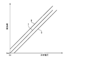
- the current characteristic that flows in the LED 1 with respect to the comparison voltage is an ideal characteristic as indicated by reference numeral 7 in FIG. 2, the comparison voltage-current characteristic is obtained as indicated by reference numeral 8 or 9 due to the offset of the comparator 4.
- the characteristic indicated by reference numeral 8 even if the comparison voltage is 0V, there is a problem that a current flows through the LED 1 and the LED 1 emits light.
- a pulse width modulation method in which the current amplitude is constant and the lighting time is adjusted for modulation can be considered.
- the LED driver when used for an application such as a lighting fixture, electromagnetic noise due to switching due to current ON and OFF is large, and the possibility of being unsuitable as a fixture increases. Therefore, a method is desired that can avoid pulse width modulation as much as possible and reduce the current value itself.
- an operational amplifier with a small offset voltage is generally prepared as a comparator, or offset adjustment is individually performed using a device such as a variable resistor.
- a device such as a variable resistor.
- Such a problem is not limited to a driving device that drives an LED, but also exists in a driving device that drives another light emitting element such as an organic EL element.
- the problem to be solved by the present invention includes the above-mentioned drawbacks as an example, and there is provided a driving device for a light emitting element capable of improving the accuracy when the light emitting element is driven with a small current with a relatively simple configuration. It is an object of the present invention to provide.
- a driving device for a light-emitting element a detection unit that detects a voltage corresponding to a current flowing through a first resistor for current detection connected in series with the light-emitting element, and detection by the detection unit
- a light emitting drive device comprising: a comparing means for comparing the magnitude of the voltage and the comparison voltage; and a drive voltage source for applying a voltage corresponding to a comparison result by the comparing means to a series circuit of the light emitting element and the first resistor. And it is characterized by having the offset means which correct
- the voltage corresponding to the current flowing through the first resistor for current detection is detected as a voltage corrected by the correction voltage by the detection means, and the detected voltage is compared with the comparison voltage, Since the drive voltage according to the comparison result is applied to the series circuit with the first resistor and the light emitting element, even if there is an offset in the comparing means, the light emitting element flows to the light emitting element according to the comparison voltage when driving a small current.
- the current value can be controlled to a desired current value.
- FIG. 3 is a diagram showing comparison voltage-current characteristics of the LED driver of FIG. 2. It is a figure for demonstrating the setting method of a correction voltage. It is a block diagram which shows the structure of an LED driver as another Example of this invention.
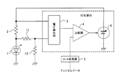
- FIG. 3 shows the configuration of an LED driver as an embodiment of the present invention.
- the LED driver shown in FIG. 3 includes a resistor 11 and a constant current source 12 in addition to the configuration of the LED driver shown in FIG.
- the resistor 11 has one end connected to the connection point between the LED 1 and the current detection resistor 2 and the other end connected to the constant current source 12.
- the resistor 11 is set to a value larger than the resistance value of the current detection resistor 2.
- the constant current source 12 is configured to flow a current having a predetermined value through the resistor 11.
- the voltage detector 3 detects a voltage between the other end of the resistor 2 (a terminal on the positive voltage output side of the variable voltage source 6) and a connection point between the resistor 11 and the constant current source 12.
- the part consisting of the resistor 11 and the constant current source 12 corresponds to the offset means.
- the current from the variable voltage source 6 flows into the ground through the current detection resistor 2 and the LED 1, and also through the current detection resistor 2, the resistor 11, and the constant current source 12. Flow into ground. A constant current always flows through the resistor 11 by the constant current source 12.
- the voltage detector 3 detects the total voltage of the voltage across the current detection resistor 2 and the voltage across the resistor 11. A voltage between both ends of the resistor 11 is a correction voltage, which is a constant voltage.
- variable voltage source 6 When the voltage detected by the voltage detector 3 is higher than the comparison voltage, the variable voltage source 6 reduces the drive voltage according to the difference voltage. On the other hand, when the detection voltage is lower than the comparison voltage, the variable voltage source 6 according to the difference voltage. Increases the drive voltage. The driving voltage is applied to a series circuit of the resistor 2 and the LED 1. Since this operation is performed continuously, the current flowing through the LED 1 can be controlled to a constant current value corresponding to the digital data.
- the comparison voltage-current characteristic is shifted in the positive direction of the comparison voltage by the amount that the correction voltage is added to the voltage across the current detection resistor 2.
- the characteristics of reference numerals 7a, 8a, 9a in FIG. 4 are shown as shifts with respect to the characteristics of reference numerals 7, 8, 9 in FIG.
- the LED current value 0 can be obtained with respect to the comparison voltage in the relationship between the comparison voltage and the current flowing through the LED 1. Further, the LED current value can be linearly increased from 0 as the comparison voltage increases.
- the input digital data is a value added by the amount corresponding to the correction voltage. Therefore, the comparison voltage supplied to the comparator 4 by converting the digital data into an analog voltage by the D / A converter 5 is a voltage obtained by adding the correction voltage to the voltage corresponding to the current value to be passed through the LED 1.
- the correction voltage is higher than the maximum offset voltage.
- the offset voltage is a voltage generated between both ends of the resistor 2 when the voltages applied to the two input terminals of the comparator 4 are both 0V in the configuration of the LED driver of FIG. 1, that is, an error voltage of the detection voltage.
- the currents flowing for two different comparison voltages that are equal to or greater than the maximum value of the offset voltage are measured, and as shown in FIG. A straight line passing through A and B is set as a comparison voltage-current characteristic, and when the characteristic is current 0 (point C), the voltage can be set by predicting it as a correction voltage.
- the voltage obtained by adding the correction voltage to the voltage across the current detection resistor is compared with the comparison voltage, and the voltage according to the comparison result is compared with the current detection resistor and the LED. Since the configuration is applied to the series circuit, even if the comparator 4 has an offset, the value of the current flowing through the LED 1 can be controlled to a desired current value according to the comparison voltage when the LED 1 is driven with a small current.
- an LED driver in which the voltage detection unit 3, the comparator 4, and the variable voltage source 6 are integrated into an IC has an advantage that the IC portion can be used as it is.
- FIG. 6 shows the configuration of an LED driver as another embodiment of the present invention.
- the LED driver shown in FIG. 6 includes two resistors 11 and 13 in addition to the configuration of the LED driver shown in FIG.
- One end of the resistor 11 is connected to the connection point between the LED 1 and the current detection resistor 2, and the other end is connected to one end of the resistor 13.
- the other end of the resistor 13 is grounded.
- the voltage detector 3 detects a voltage between the other end of the resistor 2 (a terminal on the positive voltage output side of the variable voltage source 6) and a connection point between the resistor 11 and the resistor 13.
- the LED driver of this other embodiment has a configuration in which the constant current source 12 of the LED driver of FIG.
- the voltage detector 3 detects the total voltage of the voltage across the current detection resistor 2 and the voltage across the resistor 11.
- the voltage across the resistor 11 is the correction voltage.
- the correction voltage is a voltage higher than the offset voltage, and is determined according to the current branched from the current detection resistor 2 and flowing through the resistor 11 and the resistor 13, that is, according to the anode potential of the LED 1.
- variable voltage source 6 When the voltage detected by the voltage detector 3 is higher than the comparison voltage, the variable voltage source 6 reduces the drive voltage according to the difference voltage. On the other hand, when the detection voltage is lower than the comparison voltage, the variable voltage source 6 according to the difference voltage. Is the same as the LED driver of FIG.
- an example of an LED driver that drives an LED as a light-emitting element has been shown.
- a light emitting element may be used.
- the cathode of the LED 1 is directly grounded, but may be grounded via another voltage source (for example, the power source of the comparator 4).
- the output voltage of the D / A converter 5 is not limited to the comparison voltage as it is, but the comparison voltage may be obtained by dividing the output voltage of the D / A converter 5.
- the anode of the LED 1 is connected to one end of the resistor 2
- the terminal on the positive voltage output side of the variable voltage source 6 is connected to the other end of the resistor 2
- the cathode of the LED 1 and the variable voltage source 6 is grounded
- the cathode of LED 1 is connected to one end of resistor 2
- the negative voltage output side terminal of variable voltage source 6 is connected to the other end of resistor 2.
- the anode and the terminal on the positive voltage output side of the variable voltage source 6 may be grounded. In this case, since the detection voltage is detected as a negative voltage, the detection voltage is increased to the negative voltage side by the correction voltage.
- the drive device of the present invention can be applied to a current drive type illumination device such as an LED illumination device or an organic EL illumination device.
Landscapes
- Circuit Arrangement For Electric Light Sources In General (AREA)
- Led Devices (AREA)
Abstract
Description
2 電流検出用抵抗
3 電圧検出部
4 比較器
6 可変電圧源
12 定電流源
Claims (7)
- 発光素子と直列に接続された電流検出用の第1抵抗を流れる電流に応じた電圧を検出する検出手段と、
前記検出手段の検出電圧と比較電圧との大小を比較する比較手段と、
前記比較手段による比較結果に応じた電圧を前記発光素子と前記第1抵抗との直列回路に印加する駆動電圧源と、を備える駆動装置であって、
前記第1抵抗を流れる電流に応じた電圧を補正電圧だけ補正するオフセット手段を有することを特徴とする駆動装置。 - 前記オフセット手段は、第2抵抗と定電流源との直列回路からなり、当該直列回路の第2抵抗は前記第1抵抗に接続され、
前記検出手段は前記第1抵抗と前記駆動電圧源との接続点と、前記第2抵抗と前記定電流源との接続点との間の電圧を検出することを特徴とする請求項1記載の駆動装置。 - 前記オフセット手段は、第2抵抗と第3抵抗との直列回路からなり、当該直列回路の第2抵抗は前記第1抵抗に接続され、
前記検出手段は前記第1抵抗と前記駆動電圧源との接続点と、前記第2抵抗と前記第3抵抗との接続点との間の電圧を検出することを特徴とする請求項1記載の駆動装置。 - 前記補正電圧は前記比較手段のオフセットにより生じる前記検出電圧の誤差電圧の最大値より大であることを特徴とする請求項1~3のいずれか1記載の駆動装置。
- 前記補正電圧は一定電圧であることを特徴とする請求項1又は2記載の駆動装置。
- 前記比較電圧は、前記発光素子に流すべき電流値に対応した電圧を前記補正電圧だけ加算補正した電圧であることを特徴とする請求項1~5のいずれか1記載の駆動装置。
- 前記補正電圧は、前記検出電圧の誤差電圧の最大値以上の2つの異なる値の前記比較電圧に対して前記発光素子を流れる電流を測定し、前記2つの異なる値の前記比較電圧とそれらに対する当該測定結果の電流値に応じて電流値が0となるときの前記比較電圧の値を前記補正電圧と予測することにより設定されることを特徴とする請求項4記載の駆動装置。
Priority Applications (3)
| Application Number | Priority Date | Filing Date | Title |
|---|---|---|---|
| US13/982,632 US9215766B2 (en) | 2011-02-01 | 2011-02-01 | Drive device for light-emitting element |
| JP2011522186A JP4813629B1 (ja) | 2011-02-01 | 2011-02-01 | 発光素子の駆動装置 |
| PCT/JP2011/052036 WO2012104996A1 (ja) | 2011-02-01 | 2011-02-01 | 発光素子の駆動装置 |
Applications Claiming Priority (1)
| Application Number | Priority Date | Filing Date | Title |
|---|---|---|---|
| PCT/JP2011/052036 WO2012104996A1 (ja) | 2011-02-01 | 2011-02-01 | 発光素子の駆動装置 |
Publications (1)
| Publication Number | Publication Date |
|---|---|
| WO2012104996A1 true WO2012104996A1 (ja) | 2012-08-09 |
Family
ID=45044206
Family Applications (1)
| Application Number | Title | Priority Date | Filing Date |
|---|---|---|---|
| PCT/JP2011/052036 Ceased WO2012104996A1 (ja) | 2011-02-01 | 2011-02-01 | 発光素子の駆動装置 |
Country Status (3)
| Country | Link |
|---|---|
| US (1) | US9215766B2 (ja) |
| JP (1) | JP4813629B1 (ja) |
| WO (1) | WO2012104996A1 (ja) |
Cited By (1)
| Publication number | Priority date | Publication date | Assignee | Title |
|---|---|---|---|---|
| JP2021170435A (ja) * | 2020-04-14 | 2021-10-28 | サンケン電気株式会社 | Led電源装置及びled調光方法 |
Citations (4)
| Publication number | Priority date | Publication date | Assignee | Title |
|---|---|---|---|---|
| JPH04235356A (ja) * | 1991-01-11 | 1992-08-24 | Nec Corp | 出力電流検出回路 |
| JP2000347613A (ja) * | 1999-06-03 | 2000-12-15 | Mitsubishi Electric Corp | 発光ダイオードの駆動回路 |
| JP2002290215A (ja) * | 2001-03-28 | 2002-10-04 | Seiko Instruments Inc | オフセット付コンパレータ |
| JP2004134231A (ja) * | 2002-10-10 | 2004-04-30 | Matsushita Electric Works Ltd | 照明制御装置 |
Family Cites Families (2)
| Publication number | Priority date | Publication date | Assignee | Title |
|---|---|---|---|---|
| US8773038B2 (en) * | 2011-08-26 | 2014-07-08 | Infineon Technologies Ag | Driver circuit for efficiently driving a large number of LEDs |
| CN102523666B (zh) * | 2012-01-16 | 2013-08-14 | 矽力杰半导体技术(杭州)有限公司 | 一种高效率的led驱动电路及其驱动方法 |
-
2011
- 2011-02-01 WO PCT/JP2011/052036 patent/WO2012104996A1/ja not_active Ceased
- 2011-02-01 JP JP2011522186A patent/JP4813629B1/ja not_active Expired - Fee Related
- 2011-02-01 US US13/982,632 patent/US9215766B2/en active Active
Patent Citations (4)
| Publication number | Priority date | Publication date | Assignee | Title |
|---|---|---|---|---|
| JPH04235356A (ja) * | 1991-01-11 | 1992-08-24 | Nec Corp | 出力電流検出回路 |
| JP2000347613A (ja) * | 1999-06-03 | 2000-12-15 | Mitsubishi Electric Corp | 発光ダイオードの駆動回路 |
| JP2002290215A (ja) * | 2001-03-28 | 2002-10-04 | Seiko Instruments Inc | オフセット付コンパレータ |
| JP2004134231A (ja) * | 2002-10-10 | 2004-04-30 | Matsushita Electric Works Ltd | 照明制御装置 |
Cited By (2)
| Publication number | Priority date | Publication date | Assignee | Title |
|---|---|---|---|---|
| JP2021170435A (ja) * | 2020-04-14 | 2021-10-28 | サンケン電気株式会社 | Led電源装置及びled調光方法 |
| JP7409209B2 (ja) | 2020-04-14 | 2024-01-09 | サンケン電気株式会社 | Led電源装置及びled調光方法 |
Also Published As
| Publication number | Publication date |
|---|---|
| JP4813629B1 (ja) | 2011-11-09 |
| JPWO2012104996A1 (ja) | 2014-07-03 |
| US9215766B2 (en) | 2015-12-15 |
| US20130320884A1 (en) | 2013-12-05 |
Similar Documents
| Publication | Publication Date | Title |
|---|---|---|
| JP5464204B2 (ja) | 発光駆動装置 | |
| KR101676440B1 (ko) | 백라이트 유닛, 이의 구동 방법 및 이상 검출 방법 | |
| JP6578126B2 (ja) | 光源の駆動回路およびその制御回路、照明装置、電子機器 | |
| JP5762755B2 (ja) | 発光素子の駆動回路およびそれを用いた発光装置 | |
| US8648548B2 (en) | Current generator | |
| US20160353533A1 (en) | Semiconductor light source drive device | |
| JP2014160803A (ja) | Led駆動装置 | |
| CN103108445B (zh) | 驱动发光二极管的电路及方法 | |
| JP2010015728A (ja) | バックライト調光制御装置 | |
| JP2014075492A5 (ja) | ||
| TWI584673B (zh) | 發光元件驅動電路 | |
| US8350495B2 (en) | Device driver providing compensation for aging | |
| JP4813629B1 (ja) | 発光素子の駆動装置 | |
| TWI572875B (zh) | 故障檢測電路及採用該故障檢測電路檢測電路故障的方法 | |
| US20160094291A1 (en) | Optical communication device and control method thereof | |
| JP6137969B2 (ja) | 電流検出回路、電流制御装置 | |
| US9494961B2 (en) | Feedback device and method for constant current driver | |
| KR101748660B1 (ko) | 광량 보상 기능을 구비한 led 모듈의 제어 장치 및 이를 포함하는 조명 시스템 | |
| WO2013111377A1 (ja) | Led点灯装置 | |
| JP7409209B2 (ja) | Led電源装置及びled調光方法 | |
| JP2013097928A (ja) | 発光素子の駆動回路およびそれを用いた発光装置、ディスプレイ装置 | |
| KR20120017914A (ko) | Led 구동 장치 | |
| JP7022919B2 (ja) | 照明光通信装置および通信モジュール | |
| KR102175899B1 (ko) | 발광제어장치 및 액정표시장치 | |
| TWI392205B (zh) | 一種直流電產生器及其使用之一種脈衝產生器 |
Legal Events
| Date | Code | Title | Description |
|---|---|---|---|
| WWE | Wipo information: entry into national phase |
Ref document number: 2011522186 Country of ref document: JP |
|
| 121 | Ep: the epo has been informed by wipo that ep was designated in this application |
Ref document number: 11857594 Country of ref document: EP Kind code of ref document: A1 |
|
| NENP | Non-entry into the national phase |
Ref country code: DE |
|
| WWE | Wipo information: entry into national phase |
Ref document number: 13982632 Country of ref document: US |
|
| 122 | Ep: pct application non-entry in european phase |
Ref document number: 11857594 Country of ref document: EP Kind code of ref document: A1 |