WO2012102396A1 - 光学素子の製造方法、光学素子及び撮像ユニット - Google Patents
光学素子の製造方法、光学素子及び撮像ユニット Download PDFInfo
- Publication number
- WO2012102396A1 WO2012102396A1 PCT/JP2012/051885 JP2012051885W WO2012102396A1 WO 2012102396 A1 WO2012102396 A1 WO 2012102396A1 JP 2012051885 W JP2012051885 W JP 2012051885W WO 2012102396 A1 WO2012102396 A1 WO 2012102396A1
- Authority
- WO
- WIPO (PCT)
- Prior art keywords
- refractive index
- optical element
- sample
- humidity
- temperature
- Prior art date
- Legal status (The legal status is an assumption and is not a legal conclusion. Google has not performed a legal analysis and makes no representation as to the accuracy of the status listed.)
- Ceased
Links
Images




Classifications
-
- G—PHYSICS
- G02—OPTICS
- G02B—OPTICAL ELEMENTS, SYSTEMS OR APPARATUS
- G02B13/00—Optical objectives specially designed for the purposes specified below
- G02B13/001—Miniaturised objectives for electronic devices, e.g. portable telephones, webcams, PDAs, small digital cameras
- G02B13/0055—Miniaturised objectives for electronic devices, e.g. portable telephones, webcams, PDAs, small digital cameras employing a special optical element
- G02B13/006—Miniaturised objectives for electronic devices, e.g. portable telephones, webcams, PDAs, small digital cameras employing a special optical element at least one element being a compound optical element, e.g. cemented elements
-
- B—PERFORMING OPERATIONS; TRANSPORTING
- B29—WORKING OF PLASTICS; WORKING OF SUBSTANCES IN A PLASTIC STATE IN GENERAL
- B29C—SHAPING OR JOINING OF PLASTICS; SHAPING OF MATERIAL IN A PLASTIC STATE, NOT OTHERWISE PROVIDED FOR; AFTER-TREATMENT OF THE SHAPED PRODUCTS, e.g. REPAIRING
- B29C35/00—Heating, cooling or curing, e.g. crosslinking or vulcanising; Apparatus therefor
- B29C35/02—Heating or curing, e.g. crosslinking or vulcanizing during moulding, e.g. in a mould
- B29C35/08—Heating or curing, e.g. crosslinking or vulcanizing during moulding, e.g. in a mould by wave energy or particle radiation
- B29C35/0805—Heating or curing, e.g. crosslinking or vulcanizing during moulding, e.g. in a mould by wave energy or particle radiation using electromagnetic radiation
-
- B—PERFORMING OPERATIONS; TRANSPORTING
- B29—WORKING OF PLASTICS; WORKING OF SUBSTANCES IN A PLASTIC STATE IN GENERAL
- B29C—SHAPING OR JOINING OF PLASTICS; SHAPING OF MATERIAL IN A PLASTIC STATE, NOT OTHERWISE PROVIDED FOR; AFTER-TREATMENT OF THE SHAPED PRODUCTS, e.g. REPAIRING
- B29C71/00—After-treatment of articles without altering their shape; Apparatus therefor
- B29C71/02—Thermal after-treatment
-
- G—PHYSICS
- G02—OPTICS
- G02B—OPTICAL ELEMENTS, SYSTEMS OR APPARATUS
- G02B3/00—Simple or compound lenses
- G02B3/0006—Arrays
- G02B3/0012—Arrays characterised by the manufacturing method
- G02B3/0031—Replication or moulding, e.g. hot embossing, UV-casting, injection moulding
-
- B—PERFORMING OPERATIONS; TRANSPORTING
- B29—WORKING OF PLASTICS; WORKING OF SUBSTANCES IN A PLASTIC STATE IN GENERAL
- B29C—SHAPING OR JOINING OF PLASTICS; SHAPING OF MATERIAL IN A PLASTIC STATE, NOT OTHERWISE PROVIDED FOR; AFTER-TREATMENT OF THE SHAPED PRODUCTS, e.g. REPAIRING
- B29C35/00—Heating, cooling or curing, e.g. crosslinking or vulcanising; Apparatus therefor
- B29C35/02—Heating or curing, e.g. crosslinking or vulcanizing during moulding, e.g. in a mould
- B29C35/08—Heating or curing, e.g. crosslinking or vulcanizing during moulding, e.g. in a mould by wave energy or particle radiation
- B29C35/0805—Heating or curing, e.g. crosslinking or vulcanizing during moulding, e.g. in a mould by wave energy or particle radiation using electromagnetic radiation
- B29C2035/0827—Heating or curing, e.g. crosslinking or vulcanizing during moulding, e.g. in a mould by wave energy or particle radiation using electromagnetic radiation using UV radiation
Definitions
- the present invention relates to a method for manufacturing an optical element, an optical element manufactured using the manufacturing method, and an imaging unit including the optical element.
- these resins are heated to a high temperature in the reflow process after the lens is manufactured, so that the curing of the resin proceeds, the refractive index of the resin changes, and the optical performance as an optical element may be deteriorated. is there.
- Patent Document 1 the molded article after injection molding and curing is conditioned so that the water absorption rate satisfies a predetermined condition.
- the degree of curing and the refractive index of the optical element may fluctuate due to subsequent heating in the reflow process, and it may not be possible to obtain an optical element having the desired refractive index. This problem is particularly noticeable when the reflow processing temperature is high.
- Patent Document 1 does not consider the influence of the reflow process at such a high temperature on the optical performance, and the optical performance of the optical element may change before and after the reflow process.
- Patent Document 1 does not support a reflow compatible lens.
- Patent Document 2 it is necessary to make into the target degree of hardening about the hardening part in a molding process, the hardening part in a post-cure process, and also the hardening part in a reflow process about a resin composition. For example, when there is a machine difference in the apparatus used for the reflow process, there may be a case where the reflow process temperature is different and the degree of ultimate curing is not expected.
- the degree of curing and the refractive index of the optical element may fluctuate due to moisture absorption in each step, and an optical element having a desired refractive index may not be obtained.
- the optical characteristics of the optical element before the reflow process are accurately determined in order to correctly estimate the effect on the optical performance due to the reflow process.
- Patent Document 2 has a problem that the characteristics of the optical element cannot be grasped before the reflow process.
- the present invention relates to a method of manufacturing an optical element using an energy curable resin material, wherein a difference in refractive index due to moisture absorption is relatively large in a resin obtained by curing the energy curable resin material, and the optical It is an object of the present invention to provide an optical element manufacturing method capable of manufacturing an optical element having a desired refractive index even when the element is subjected to reflow treatment after manufacturing. Furthermore, an object of this invention is to provide the optical element manufactured using the said manufacturing method, and an imaging unit provided with this optical element.
- an optical element manufacturing method includes a molding process for molding an optical element using an energy curable resin material, and a heat treatment according to a reflow process planned for the optical element.
- the high-temperature heating process corresponding to the planned reflow process, a heat process corresponding to this is performed, and by substantially completing the curing of the resin, the progress of the curing of the resin in the subsequent reflow process is suppressed, It is possible to prevent the refractive index from changing as the resin cures.
- the humidity of the optical element such as the lens unit in the humidity adjustment process after the high-temperature heating process, even with an optical element using a resin having a large refractive index difference due to moisture absorption or the like, the desired optical performance can be obtained. Therefore, it is possible to manufacture a lens unit having the desired optical performance, that is, an imaging lens.
- optical performance can be correctly evaluated by performing performance evaluation of an optical element after performing a humidity control process.
- the optical element after the high-temperature heat treatment and the humidity control treatment is performed after the reflow treatment, which is assumed to be performed thereafter, and the refractive index before the reflow treatment.
- the difference from the refractive index in the normal environment can be made relatively small. Thereby, an optical element with high optical performance can be provided.
- the refractive index may change when the degree of curing of the resin changes.
- the energy curable resin used in the present invention is manufactured through the humidity control step without passing through the high temperature heating step after the molding step and the refractive index of the optical element manufactured through the molding step, the high temperature heating step and the humidity control step.
- the difference between the refractive indexes of the other optical elements is 0.00050 or more.
- heat treatment according to the reflow treatment scheduled thereafter is performed, and by substantially completing the curing of the resin, the resin before and after the actual reflow treatment is processed. Make sure that the curing does not change.
- the energy curable resin used in the present invention is a curable resin having performance such as transparency, weather resistance, surface shape stability, and refractive index stability, such as an epoxy resin and an acrylic resin.
- the water absorption is large.
- the refractive index of the energy curable resin at a predetermined temperature and 0% humidity The absolute value of the difference from the refractive index of the energy curable resin at a humidity of 100% has a characteristic of 0.00100 or more.
- the refractive index of the resin changes greatly.
- the optical performance of the optical element may be reduced from the expected performance.
- the optical element in the humidity control step, is placed in a thermostatic bath in which temperature and humidity are kept constant for 3 hours or more.
- the optical element can be optically sufficiently stable.
- the temperature in the thermostat can be kept stable at an arbitrary temperature, and the humidity in the thermostat is kept within a range of 50% ⁇ 30%. be able to.
- the optical element is based on room temperature, that is, 23 ° C. according to JIS K7100, and this reference temperature is 23 ° C. ⁇ 10 ° C., preferably 23 It shall be placed for 3 hours or more in an environment of ⁇ 5 ° C and a humidity of 50% ⁇ 30%. Desirably, the humidity is 50% ⁇ 15%.
- the optical element can be optically sufficiently stable.
- the refractive index of a resin can vary depending on the temperature of the resin and the amount of moisture in the resin. Resin adapts quickly to the surrounding environment temperature and adapts to the surrounding environment temperature in a few minutes.
- the temperature at the time of humidity adjustment has little effect on the optical performance of the optical element, but it is room temperature, that is, JIS In accordance with K7100, it is preferable to control the humidity at 23 ° C. ⁇ 10 ° C., preferably 23 ° C. ⁇ 5 ° C., based on 23 ° C.
- the rate at which the resin absorbs ambient moisture is slower than the rate of temperature change, and it takes about several tens of minutes to several hours to fully adapt to the humidity in a given environment. Therefore, in the present invention, the humidity condition is more important than the temperature condition.
- the refractive index of the optical element produced through the molding process, the high-temperature heating process and the humidity control process, and the normal environment after further reflow treatment on the optical element is adjusted so that the absolute value of the difference in refractive index is less than 0.00050 with respect to the refractive index of the optical element at an environment of temperature 23 ° C. ⁇ 10 ° C. and humidity 50% ⁇ 30%. Even if the optical element that has undergone the high-temperature heating process and the humidity control process is subjected to a reflow process later, the difference in refractive index before the reflow process is relatively small because a predetermined moisture absorption is performed later. It has a refractive index.
- the performance evaluation of the optical performance of the optical element is performed after the humidity control step.
- the measurement results and inspection results as performance evaluations were obtained after humidity control was performed after passing through the pseudo reflow process, and therefore correctly reflected the optical performance of the optical elements such as the lens unit. Become.
- the method further includes a packing step of packing the optical element that has undergone the humidity adjustment step with a packing material.
- a packing material By packing the optical element with the packing material, it is possible to keep the refractive index of the optical element in a predetermined state and place it in the distribution process such as shipping, delivery, etc., and reflow processing the optical element after distribution
- the optical element has an intended refractive index by being subjected to predetermined moisture absorption.
- the packing material a material having low water permeability, specifically, a material having a water permeability of 20 g / m 2 ⁇ 24 h or less can be used.
- the refractive index of the optical element can be reliably maintained in a predetermined state and placed in a distribution process such as shipment or delivery.
- a distribution process such as shipment or delivery.
- unnecessary moisture absorption during transportation can be prevented, and the optical performance after manufacturing the optical element and the change in the optical performance of the optical element before reflowing can be reduced. Can be prevented.
- the energy curable resin is a photocurable resin.
- the desired refractive index is obtained after the reflow treatment through the high-temperature heating step and moisture absorption.
- the optical element according to the present invention is manufactured by any one of the optical element manufacturing methods described above.
- the manufactured optical element can have a relatively small refractive index difference before and after mounting by the reflow process, and has the desired optical performance.
- an imaging unit includes the above-described optical element, an imaging element that detects an image formed by the optical element, and a holder portion that supports at least the optical element.
- the imaging unit has increased reliability after fabrication in mounting by reflow processing.
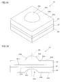
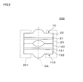
- FIG. 1 (A) and 1 (B) are a perspective view and a sectional view of an optical element according to the first embodiment. It is sectional drawing of the lens unit which combined the optical element. It is a flowchart for demonstrating the manufacturing method of an optical element.
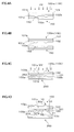
- 4 (A) to 4 (D) are diagrams for explaining a molding process of a wafer lens to be an optical element in the optical element manufacturing method. It is a conceptual diagram for demonstrating a high temperature heating process among the manufacturing methods of an optical element.
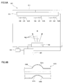
- FIG. 6A is a conceptual diagram for explaining a film forming process in the method for manufacturing an optical element
- FIG. 6B is a cross-sectional view of the optical element after film formation.
- a first lens unit 10 which is an optical element manufactured by the method for manufacturing an optical element according to this embodiment includes a substrate 21, a first lens element 22, and And a second lens element 23.
- the first lens unit 10 has a square and block-shaped outer shape in plan view.
- substrate 21 is a rectangular flat plate in planar view, and is formed with glass. Similarly, the substrate 21 is sandwiched between the first and second lens elements 22 and 23 that are rectangular in plan view.
- the first lens element 22 is made of resin, and is formed on one surface 21 a of the substrate 21.
- the first lens element 22 has a first lens body 22a and a first flange portion 22b.
- the first lens body 22a is, for example, a convex aspherical or spherical lens part, and has an optical surface 22c.
- the first flange portion 22b around the first lens body 22a has a flat first flange surface 22d extending perpendicularly to the optical axis OA around the optical surface 22c.
- the first lens element 22 is formed of an energy curable resin such as a photocurable resin or a thermosetting resin.
- the photocurable resin material and the thermosetting resin material contain a polymerizable composition, a polymerization initiator that initiates polymerization of the polymerizable composition, that is, a curing agent, and the like.
- the resin used for the first lens element 22 is, as a property immediately after curing, an energy curable resin at a reference temperature (here 23 ° C.) and humidity 0% in a state where the curing of the resin is substantially completed.
- the absolute value of the difference in refractive index between the refractive index and the refractive index of the energy curable resin at the same temperature and 100% humidity is 0.00100 or more, and the difference in refractive index due to moisture absorption is relatively low. It can be said that it is big.
- the second lens element 23 is made of resin like the first lens element 22, and is formed on the other surface 21 b of the substrate 21.
- the second lens element 23 has a second lens body 23a and a second flange portion 23b.
- the second lens body 23a is, for example, a concave aspherical or spherical lens portion, and has an optical surface 23c.
- the second flange portion 23b around the second lens body 23a has a flat second flange surface 23d that extends perpendicular to the optical axis OA around the optical surface 23c.
- the resin used for the second lens element 23 is the same as the resin for the first lens element 22. However, both lens elements 22 and 23 need not be formed of the same resin, and can be formed of different resins.
- the first lens unit 10 is an optical element for image formation, and can be used alone or in combination.
- the first lens unit 10 may constitute an imaging lens alone, but as shown in FIG. 2, the first lens unit 10 is a second lens having the same structure as the first lens unit 10, for example.
- an imaging lens 200 used for a mobile phone camera or the like is configured.
- the imaging lens 200 may include a holder 201 for integrating the lens units 10 and 110 in addition to the first lens unit 10 and the second lens unit 110.
- the second lens unit 110 includes a substrate 121 and first and second lens elements 122 and 123 sandwiching the substrate 121 as in the first lens unit 10.
- the first lens unit 10 and the second lens unit 110 are fixed with an adhesive or the like in a stacked state, whereby the imaging lens 200 is manufactured.
- the imaging lens 200 functions as an imaging lens of the imaging unit by being bonded to an imaging circuit board described later.
- the wafer lens 100 is formed by the steps shown in FIGS. 4 (A) to 4 (D) (see FIG. 4 (D)).
- a resin material 102b (an uncured resin material for obtaining a photocurable resin for forming the first lens element 22) is applied on a mold 150, and an appropriate interval is set.
- the substrate glass 101 is pressed from above so that the resin material 102b sandwiched therebetween is cured by irradiating ultraviolet rays with a UV generator (not shown).
- the transfer surface 153 of the mold 150 is transferred to the resin material 102b, and the first molding surface 102a (the first optical surface 22c and the first flange surface 22d) is formed on the cured resin. Thereby, the first resin layer 102 is formed.
- the first resin layer 102 and the substrate glass 101 are integrally released from the mold 150 to produce an intermediate 100m to be the wafer lens 100.
- a resin material 103b (an uncured resin material for obtaining a photocurable resin for forming the second lens element 23) is applied on the mold 250. Then, the mold 250 is pressed from above so as to have an appropriate interval, and the resin material 103b sandwiched therebetween is cured by irradiating ultraviolet rays. At this time, the transfer surface 253 of the mold 250 is transferred to the resin material 103b, and the second molding surface 103a (the second optical surface 23c and the second flange surface 23d) is formed on the cured resin. Thus, the second resin layer 103 is formed and released from the mold 250, and the wafer lens 100 is manufactured.
- the wafer lens 100 can be molded using the master mold formed of metal or the like as it is, but the resin-made sub master mold is formed from the master mold, and the wafer lens 100 is molded using the sub master mold. You can also. Furthermore, it is possible to form a resin sub-submaster mold using the sub-master mold as a molding mold, and mold the wafer lens 100 from the sub-submaster mold.
- step S1 in FIG. 3 the molding process of step S1 in FIG. 3 is performed, photocuring by irradiation with ultraviolet rays is finished, and the wafer lens 100 is manufactured.
- auxiliary heating in step S2 of FIG. 3 for example, an auxiliary heating process of heating at 200 ° C. for about 1 hour using a vacuum oven (not shown) is performed. Using the heating at 200 ° C. for 1 hour, the curing process in step S2 is completed.
- an epoxy resin or the like is used to form the resin layers 102 and 103
- an auxiliary heating process is performed as a normal curing process in order to shorten the curing time in addition to the irradiation with the ultraviolet rays.
- the conditions of this heat processing are suitably set according to the kind of photocurable resin which forms the resin layers 102 and 103.
- the wafer lens 100 is subjected to a high temperature heat treatment.
- the high temperature heating process of the wafer lens 100 by the heating device 30 (high temperature heating process of step S3 in FIG. 3) will be described with reference to FIG.
- the heating device 30 includes a heating chamber 31 having a heat insulating wall, a pair of heaters 32 that raise the temperature in the heating chamber 31, a temperature sensor 33 that measures the temperature in the heating chamber 31, and air from the inside of the heating chamber 31. It is a vacuum oven provided with the vacuum pump 34 to remove and the control apparatus 35 which controls these.
- the wafer lens 100 installed in the heating chamber 31 of the heating device 30 is heated at a target temperature and vacuum environment by the heater 32, the temperature sensor 33, and the vacuum pump 34 under the control of the control device 35.
- the heating process by the heating device 30 is performed at a temperature of 260 ° C. in the heating chamber 31 as a temperature imitating the reflow process performed in the mounting of the lens unit 10 and heating is performed for 30 minutes.
- this high-temperature heat treatment is a relatively high-temperature heat treatment that is performed at a high temperature corresponding to the scheduled reflow treatment, unlike the auxiliary heat treatment for completing the curing in step S2. Yes, it is a pseudo reflow process.
- the wafer lens 100 is sufficiently cured by the auxiliary heating process in step S2, but is more completely cured by the high temperature heating process in step S3.
- the complete curing means that the progress of curing is substantially saturated, and the refractive index of the lens unit 10 after the wafer lens 100 is singulated is almost changed due to moisture absorption even after reflow processing or the like. It means that it will not.
- the optical functional film examples include an antireflection film and a protective film. This film forming process may not be in the specifications of the optical element.
- a film forming apparatus 50 includes a film forming chamber 51 that forms a sealed space, a vapor deposition apparatus 52 that injects a film forming material to be vapor deposited, one or a plurality of wafer lenses 100, and a wafer lens.
- a film forming target MS including a holder for supporting 100 is installed at a predetermined position facing the vapor deposition apparatus 52 and displaced in the film forming chamber 51, and the inside of the film forming chamber 51 is used for vapor deposition.
- a vacuum pump 54 for making a vacuum state and a control device 55 for controlling them.
- the vapor deposition apparatus 52 which is a vapor deposition source, the vapor deposition substance which should become optical function films, such as an antireflection film and a protective film, is inject
- the wafer lens 100 installed at a predetermined position in the film forming chamber 51 of the film forming apparatus 50 is subjected to film formation by injection of a film forming substance from the vapor deposition apparatus 52 under the control of the control device 55. Is coated.
- the wafer lens 100 is in a state where the optical functional films MB such as an antireflection film and a protective film are applied on the optical surfaces 22c and 23c.
- the wafer lens 100 subjected to the film forming process by the above method is diced or cut (step S5) as shown by a broken line in FIG. By cutting out, the lens unit 10 shown in FIG.
- the second lens unit 110 which is an optical element, is also manufactured in the same process. Further, dicing (step S5) may not be performed depending on the specifications of the optical element.
- the humidity control apparatus 40 includes a humidity control chamber 41 having a heat insulating wall and forming a sealed space, an air delivery device 42a that is an air control circulation system for keeping the temperature and humidity in the humidity control chamber 41 constant, air A suction device 42b and a fan 42c, a temperature / humidity sensor 43 for measuring indoor temperature and humidity, and a control device 44 for controlling them are provided.
- the air delivery device 42a sends out air having a temperature and humidity corresponding to the normal environment assumed for the lens unit 10 that is the subject of humidity control into the humidity control chamber 41 that is a sealed space.
- the air suction device 42b sucks air in the humidity control chamber 41, and the fan 42c circulates the air in the humidity control chamber 41 to keep the air in the humidity control chamber 41 uniform.
- the lens unit 10 installed in the humidity control chamber 41 of the humidity control device 40 through a high temperature heating process by the heating device 30 (see FIG. 5) is controlled by the control device 44, and includes an air delivery device 42a and an air suction device. 42b, the fan 42c, and the temperature / humidity sensor 43 allow sufficient humidity adjustment by being placed in predetermined humidity control conditions (that is, under the temperature and humidity corresponding to the normal environment for the time necessary for the state to stabilize). That is, humidity control processing is performed.
- predetermined humidity control conditions the lens unit 10 is placed in an environment of 50% ⁇ 30% humidity for 3 hours or more. Desirably, the humidity is 50% ⁇ 15%.
- the refractive index of a resin can vary depending on the temperature of the resin and the amount of moisture in the resin. Resin has a rapid adaptation speed to the ambient temperature and adapts to the ambient temperature in a few minutes. Therefore, the temperature at the time of humidity adjustment has little influence on the optical performance of the optical element. However, the rate at which the resin absorbs ambient moisture is slower than the rate of temperature change, and it takes about several tens of minutes to several hours to fully adapt to the humidity in a given environment. Therefore, humidity conditions are more important than temperature conditions.
- the temperature at which the humidity is adjusted is normal temperature, that is, 23 ° C. in accordance with JIS K7100, and this reference temperature is 23 ° C. ⁇ 10 ° C., preferably 23 ° C. ⁇ 5 ° C.
- a state in which sufficient humidity control is performed by the humidity control device 40 under a predetermined condition is referred to as a reference state.
- step S4 it is also possible to put a humidity control process before the film-forming process (step S4) demonstrated above. In that case, after performing the dicing after the film forming process, the humidity control process is required again. Since the wafer lens 100 after the humidity adjustment process is in a state in which the moisture absorption state of the resin is stable, the refractive index and the like are also in an expected state. There is no risk of degradation of characteristics or cracking of the optical functional film MB.
- Measurement and / or inspection of the optical characteristics of the lens unit 10 is performed after the humidity control process. Specifically, various performance evaluations including surface accuracy measurement of the lens unit 10 are performed. The measurement result and the inspection result here are obtained after the humidity is adjusted after the pseudo reflow process, and thus the optical performance of the lens unit 10 is correctly reflected. Therefore, even if reflow processing is performed later, if moisture absorption is performed, the optical performance of the lens unit 10 is the same as that at the time of inspection before reflow. Optical performance can be measured correctly.
- the reflow process is a process of mounting the imaging unit on the substrate by heating the substrate and melting the solder while the imaging unit including the lens unit is placed on the substrate on which solder or the like is potted.
- the reflow process can be performed by, for example, an apparatus / procedure described in Japanese Patent Application Laid-Open No. 2010-287635.
- Specific conditions for the reflow treatment can be appropriately determined in consideration of the type of solder used, the substrate, the resin for the optical element, and the like, but generally heating at a high temperature is required. Typically, the heating is performed at a high temperature of 230 ° C. to 270 ° C. for about 5 to 10 minutes.
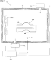
- the lens unit 10 returned to the optimum humidity control state by the humidity adjustment process in step S6 is housed in the holder HD and further packed in a sealed state by the packing material 60. . More specifically, first, the lens unit 10 is packed in a main body portion BT formed according to the shape of the lens unit 10 in the holder HD so that the lid portion TP does not rattle due to vibrations during transportation. Fixed to. Further, the lens unit 10 packaged with the holder HD is sealed with a packaging material 60.
- the packing material 60 a material having low water permeability, more specifically, a water permeability of 20 g / m 2 stipulated by the amount of water that passes for 24 hours per square meter under atmospheric pressure (1 atm). ⁇ Use materials of 24h or less.
- the lens unit 10 can be placed in a distribution process such as shipment and delivery so that the refractive index thereof is maintained in an intended state.
- the reflow process is performed after the lens unit 10 is transported, it is possible to suppress a decrease in the performance of the lens unit 10.
- FIG. 8 is a simplified illustration, and the holder HD is not limited to packaging a single lens unit 10, but may be a packaging of a plurality of lens units 10.
- the resin for forming both lens elements 22 and 23 in the lens unit 10 various energy curable resins such as a thermosetting resin and a photocurable resin are used.
- a thermosetting resin such as a thermosetting resin
- a photocurable resin an epoxy resin, an acrylic resin, an allyl ester resin, a vinyl resin, or the like can be used.
- the resin material has fluidity in an uncured state and contains at least a polymerizable composition such as a polymerizable monomer and a polymerization initiator.
- An epoxy resin is a resin obtained by curing one or more reactive monomers or oligomers or mixtures containing an epoxy group at the molecular end by polymerization.
- the type of epoxy resin is not particularly limited as long as it is polymerized and cured by light, and a cation generator having photosensitivity can be used as a curing initiator.
- Epoxy resins are preferred because they have a low cure shrinkage and can be an optical element with excellent molding accuracy. Examples of the epoxy resin suitable for optical use include novolak phenol type epoxy resin, biphenyl type epoxy resin, and dicyclopentadiene type epoxy resin.
- Examples include bisphenol F diglycidyl ether, bisphenol A diglycidyl ether, 2,2′-bis (4-glycidyloxycyclohexyl) propane, 3,4-epoxycyclohexylmethyl-3,4-epoxycyclohexanecarboxylate, vinyl Cyclohexene dioxide, 2- (3,4-epoxycyclohexyl) -5,5-spiro- (3,4-epoxycyclohexane) -1,3-dioxane, bis (3,4-epoxycyclohexyl) adipate, 1,2 -A polymer obtained by polymerizing bisglycidyl ester of cyclopropanedicarboxylic acid.
- the acrylic resin is a resin obtained by curing one or more reactive monomers containing an acrylic group (specifically, (meth) acrylate: (meth) acrylate represents acrylate or methacrylate), an oligomer, or a mixture by polymerization. is there.
- the kind of acrylic resin is not particularly limited as long as it is polymerized and cured by light, and a radical generator having photosensitivity can be used as a curing initiator.
- a kind of acrylic resin suitable for optical use for example, (meth) acrylate used in the polymerization reaction is not particularly limited, and a polymer obtained by polymerizing the following (meth) acrylate produced by a general production method is used. can do.
- (meth) acrylate having an alicyclic structure is preferable, and may be an alicyclic structure containing an oxygen atom or a nitrogen atom.
- it preferably has an adamantane skeleton.
- 2-alkyl-2-adamantyl (meth) acrylate see Japanese Patent Laid-Open No.
- Tet Curing having an adamantane skeleton having no aromatic ring such as adamantane (see JP-A-2006-169177), 2-alkyl-2-hydroxyadamantane, 2-alkyleneadamantane, di-tert-butyl 1,3-adamantanedicarboxylate Resin (see JP-A-2001-322950), bis (hydroxyphenyl) adamantanes, bis (glycidyloxyphenyl) adamantane (see JP-A-11-35522, JP-A-10-130371) and the like. .
- the allyl ester resin is a resin obtained by curing one or more reactive monomers, oligomers or mixtures containing an allyl ester group at the molecular end by polymerization.
- the kind of allyl ester resin is not particularly limited as long as it is polymerized and cured by light, and a radical generator having photosensitivity can be used as a curing initiator.
- Examples of the kind or material of the allyl ester resin suitable for optical use include, for example, bromine-containing (meth) allyl ester not containing an aromatic ring (see Japanese Patent Application Laid-Open No. 2003-66201), allyl (meth) acrylate (Japanese Patent Application Laid-Open No. Hei 5). No.
- the vinyl resin is a resin obtained by curing one or more reactive monomers or oligomers or mixtures containing a vinyl group by polymerization.
- the kind of vinyl resin is not particularly limited as long as it is polymerized and cured by light, and a radical generator having photosensitivity can be used as a curing initiator.
- a kind of vinyl resin suitable for optical applications for example, a polymer obtained by polymerizing an aromatic vinyl compound can be used.
- aromatic vinyl compound examples include, for example, styrene, ⁇ -methylstyrene, ⁇ -ethylstyrene, ⁇ -propylstyrene, ⁇ -isopropylstyrene, ⁇ -t-butylstyrene, 2-methylstyrene, and 3-methyl.
- Styrene 4-methylstyrene, 2,4-diisopropylstyrene, 2,4-dimethylstyrene, 4-t-butylstyrene, 5-t-butyl-2-methylstyrene, monochlorostyrene, dichlorostyrene, monofluorostyrene, 4 -Phenylstyrene and the like, and styrene, 2-methylstyrene, 3-methylstyrene, 4-methylstyrene and the like are preferable.
- aromatic vinyl compounds can be used alone or in combination of two or more.
- the photopolymerization initiator is a curing agent that constitutes a part of the photocurable resin.
- the photopolymerization initiator is selected according to the kind of main component resin such as epoxy resin and acrylic resin, the wavelength of light used for polymerization, and the like.
- main component resin such as epoxy resin and acrylic resin
- the photopolymerization initiator for example, n-butyllithium, sec-butyllithium, t-butyllithium, hexyllithium, monolithium such as phenyllithium, dilithiomethane, 1,4-diobtan, 1,4 -Polyfunctional organolithium compounds such as dilithio-2-ethylcyclohexane.
- additives such as a hardening accelerator
- the curing accelerator is not particularly limited as long as it has good curability, is not colored, and does not impair the transparency of the photocurable resin. Two or more types may be mixed depending on the purpose. It may be used.
- the resin used for the first lens element 22 and the second lens element 23 of the lens unit 10 has, as its property, the lens unit 10 (wafer) manufactured through the above-described molding process, high-temperature heating process, and humidity control process.
- the refractive index of the lens 100 is compared with the refractive index of another optical element manufactured through the humidity control process without passing through the high-temperature heating process after the molding process described above, the absolute difference in the refractive index is calculated.
- the value is 0.00050 or more. That is, in the above manufacturing method, passing through a high-temperature heating step and a humidity control step is meaningful for manufacturing an optical element having a desired refractive index.
- the refractive index of the lens unit 10 manufactured by each of the above steps and the moisture absorption after the reflow treatment is performed on the lens unit 10 after being packed and delivered, for example.
- the absolute value of the refractive index difference is less than 0.00050. That is, the resin has an intended refractive index after the subsequent reflow treatment and moisture absorption by passing through the high-temperature heating process and the humidity control process as described above.
- the lens unit 10 in the high-temperature heating process, a high-temperature heat treatment corresponding to the scheduled reflow process is performed, and the lens unit 10 is subjected to a specific humidity control in the subsequent humidity-control process.
- the refractive index of the lens unit 10 after being conditioned can be made relatively small in the refractive index difference before and after the reflow process that is assumed to be performed thereafter.
- the lens unit 10 having the desired refractive index and the imaging lens 200 can be manufactured.
- the temperature of the sample when measuring the refractive index is 23 ° C.
- Example 1-1 In Experimental Example 1-1, various measurements were performed using an epoxy ultraviolet curable resin material as a resin material for obtaining the resin layer 102 of the lens unit 10.
- an epoxy ultraviolet curable resin material a material obtained by adding 4 wt% of UVI-6992 manufactured by Dow Chemical as a UV curing initiator to a bisphenol A type epoxy resin monomer is used.
- this resin material was irradiated with ultraviolet rays having an irradiation amount of 3000 mJ, and then the auxiliary heating at 200 ° C. for 1 hour using the heating device (vacuum oven) 30.
- the resin material was cured to form samples 1 and 2.
- the sample 1 was stored for 3 hours in a humidity control device 40 (a constant temperature bath) set to a temperature of 23 ° C. and a relative humidity of 50%, and the refractive index was measured.
- the refractive index of the d-line was 1.52083.
- the sample 2 was heated at 260 ° C.
- the sample 2 was stored for 3 hours in a humidity control device 40 (constant temperature chamber) set at a temperature of 23 ° C. and a relative humidity of 50%, and the refractive index was measured.
- the refractive index of d-line was 1.52000.
- the refractive index of Sample 3 was measured, and as a result, the refractive index of d-line was 1.51915.
- the resin was saturated and absorbed, and the refractive index of the sample 4 was measured.
- the refractive index of the line was 1.52070. Comparing the refractive index of Sample 3 in which the resin is sufficiently dried and Sample 4 in a state in which the resin is sufficiently absorbing water, the difference is 0.00155 of 0.00100 or more, and the refractive index due to water absorption. It turns out that it is resin with a big change.
- Table 1-2 briefly summarizes the relationship between the processing contents of Samples 3 to 4 obtained in Experimental Example 1-2 and the refractive index.
- Example 1-3 Next, in order to investigate the time conditions suitable for humidity control, a resin material having the same composition as that of sample 1 is used. The resin material is irradiated with ultraviolet rays having an irradiation amount of 3000 mJ, and then a heating device (vacuum oven) 30 is used. Using this, auxiliary heating was performed at 200 ° C. for 1 hour to cure the resin material, and Samples 5 to 9 were molded. Thereafter, samples 5 to 9 were heated at 260 ° C. for 30 minutes as a pseudo-reflow corresponding to step S3, that is, high-temperature heat treatment, using a heating device (vacuum oven) 30.
- the refractive index of Sample 5 was measured, and as a result, the refractive index of d-line was 1.51915.
- the sample 6 is stored for 2 hours to adjust the humidity
- the sample 7 is stored for 3 hours to adjust the humidity
- Sample 8 was stored for 4 hours to adjust humidity
- sample 9 was stored for 5 hours to adjust humidity
- the refractive index was measured.
- the refractive index of d-line of sample 6 was 1.51944
- d of sample 7 was The refractive index of the line was 1.52000
- the refractive index of the d line of sample 8 was 1.52009
- the refractive index of the d line of sample 9 was 1.52015. From the above, it can be said that it is desirable to place the humidity control device 40 for 3 hours or more as the humidity control condition for realizing the reference state.
- Table 1-3 below briefly summarizes the relationship between the processing contents of Samples 5 to 9 obtained in Experimental Example 1-3 and the refractive index.
- Example 1-4 in order to examine the humidity conditions suitable for humidity control, a resin material having the same composition as that of sample 1 is used.
- the resin material is irradiated with ultraviolet rays having an irradiation amount of 3000 mJ, and then a heating device (vacuum oven) 30 is installed.
- auxiliary heating at 200 ° C. for 1 hour was performed to cure the resin material, and samples 10 to 16 were molded. Thereafter, samples 10 to 16 were heated at 260 ° C. for 30 minutes using a heating device (vacuum oven) 30 as a pseudo reflow corresponding to step S3, that is, high-temperature heat treatment.
- the sample 10 was stored for 3 hours in a humidity control apparatus 40 set at a temperature of 23 ° C. and a relative humidity of 20%, and the humidity was adjusted.
- the refractive index of d-line was 1.51954.
- the sample 11 was stored for 3 hours in a humidity control apparatus 40 set at a temperature of 23 ° C. and a relative humidity of 30%, and the humidity was adjusted.
- the refractive index of d-line was 1.51971.
- the sample 12 was stored for 3 hours in a humidity control apparatus 40 set at a temperature of 23 ° C. and a relative humidity of 40%, and the humidity was adjusted.
- the refractive index of d-line was 1.51985.
- the sample 13 was stored in a humidity control apparatus 40 set at a temperature of 23 ° C. and a relative humidity of 50% for 3 hours to adjust the humidity and the refractive index was measured.
- the d-line refractive index was 1.52000.
- the sample 14 was stored for 3 hours in a humidity control apparatus 40 set to a temperature of 23 ° C. and a relative humidity of 60%, and the humidity was adjusted.
- the refractive index of d-line was 1.52014. .
- the sample 15 was stored in the humidity control apparatus 40 set at a temperature of 23 ° C. and a relative humidity of 70% for 3 hours, and the humidity was adjusted.
- the refractive index of d-line was 1.52031.
- the sample 16 was stored for 3 hours in a humidity control apparatus 40 set to a temperature of 23 ° C. and a relative humidity of 80%, and the humidity was adjusted.
- the refractive index of d-line was 1.52045. .
- the refractive index is 0.00050 with respect to the refractive index when the thermostatic chamber humidity is 50%. It is in range. Table 1-4 below briefly summarizes the relationship between the processing contents of Samples 10 to 16 obtained in Experimental Example 1-4 and the refractive index.
- the sample 17 was stored and conditioned for 3 hours using a humidity control apparatus 40 (a constant temperature bath) set to a temperature of 23 ° C. and a relative humidity of 50%. Then, as a result of measuring the refractive index of the sample 17, the refractive index of d line
- the samples 18 to 20 were stored and conditioned for 3 hours using a humidity control apparatus 40 (a constant temperature bath) set to a temperature of 23 ° C. and a relative humidity of 50%. Thereafter, the sample 18 was packed with a material having a water permeability of 10 g / m 2 ⁇ 24 h, stored for 48 hours in a humidity control apparatus 40 set at a temperature of 23 ° C. and a relative humidity of 90%, and the refractive index was measured.
- the refractive index of the d-line was 1.52008.
- the sample 19 after the humidity control treatment is packed with a material having a water permeability of 15 g / m 2 ⁇ 24 h, and stored in the humidity control device 40 set at a temperature of 23 ° C. and a relative humidity of 90% for 48 hours to adjust the humidity.
- the refractive index of d-line was 1.52022.
- the sample 20 after the humidity control treatment is packed with a material having a water permeability of 20 g / m 2 ⁇ 24 h, and stored in the humidity control apparatus 40 set to a temperature of 23 ° C. and a relative humidity of 90% for 48 hours to adjust the humidity.
- the refractive index of d-line was 1.52039.
- the change in the refractive index is within 0.00050.
- Table 1-6 below briefly summarizes the relationship between the water permeability of the material packed with Samples 18-20 obtained in Experimental Example 1-6 and the refractive index of Samples 18-20.
- Example 1-7 Next, in order to investigate the resistance of the resin to environmental fluctuations, a resin material having the same composition as that of sample 1 is used. The resin material is irradiated with ultraviolet rays having an irradiation amount of 3000 mJ, and then a heating device (vacuum oven) 30 is used. Sample 21 was molded by curing the resin material by performing auxiliary heating at 200 ° C. for 1 hour. Thereafter, the sample 21 was heated at 260 ° C. for 30 minutes using a heating device (vacuum oven) 30 as a pseudo reflow corresponding to Step S3, that is, high-temperature heat treatment.
- a heating device vacuum oven
- the refractive index of sample 21 was measured, and as a result, the refractive index of d-line was 1.51915. Thereafter, the sample 21 was conditioned by storing for 3 hours using a humidity control device 40 (a constant temperature bath) set to a temperature of 23 ° C. and a relative humidity of 50%. Then, as a result of measuring the refractive index of the sample 21, the refractive index of d line became 1.52000. Thereafter, the sample 21 was stored for 168 hours using a humidity control apparatus 40 (a constant temperature bath) set to a temperature of 60 ° C. and a relative humidity of 90%. Then, as a result of measuring the refractive index of the sample 21, the refractive index of d line became 1.52068.
- the sample 21 was conditioned by storing for 3 hours using a humidity control device 40 (a constant temperature bath) set to a temperature of 23 ° C. and a relative humidity of 50%. Then, as a result of measuring the refractive index of the sample 21, the refractive index of d line
- a humidity control apparatus 40 a constant temperature bath
- the sample 21 was conditioned by storing for 3 hours using a humidity control device 40 (a constant temperature bath) set to a temperature of 23 ° C. and a relative humidity of 50%. Then, as a result of measuring the refractive index of the sample 21, the refractive index of d line
- the refractive index increases, but the refractive index almost returns to the value after the humidity-conditioning treatment after the pseudo-reflow treatment by passing through the humidity-conditioning process.
- Example 2-1 In Experimental Example 2-1, various measurements were performed using an acrylic ultraviolet curable resin material as a resin material for obtaining the resin layer 102 of the lens unit 10.
- an acrylic ultraviolet curable resin material 2-alkyl-2-adamantyl (meth) acrylate is added with 1 wt% of IRGACURE907 manufactured by Ciba Specialty Chemicals as a UV curing initiator.
- this resin material is irradiated with ultraviolet rays having an irradiation amount of 1800 mJ, and then heated at 150 ° C. for 1 hour using a heating device (vacuum oven) 30.
- the resin material was cured to form samples 22 to 23.
- the sample 22 was stored for 3 hours in a humidity control device 40 (a constant temperature bath) set at a temperature of 23 ° C. and a relative humidity of 50%, and the refractive index was measured.
- the refractive index of the d-line was 1.60090.
- the sample 23 was heated at 260 ° C.
- step S3 a heating device (vacuum oven) 30 as a pseudo reflow corresponding to step S3, that is, high-temperature heat treatment.
- a heating device vacuum oven
- step S3 high-temperature heat treatment.
- the sample 23 was stored for 3 hours in a humidity control device 40 (constant temperature chamber) set at a temperature of 23 ° C. and a relative humidity of 50%, and the refractive index was measured.
- the refractive index of the d-line was 1.6000.
- the difference was 0.00090 of 0.00050 or more, and Sample 22 not subjected to high-temperature heat treatment resulted in a higher refractive index.
- the refractive index of the sample 26 was measured, and as a result, the refractive index of d-line was 1.509905.
- a humidity control apparatus 40 (a constant temperature bath) set at a temperature of 23 ° C. and a relative humidity of 50%, the sample 27 is stored for 2 hours to adjust the humidity, and the sample 28 is stored for 3 hours to adjust the humidity. 29 was stored for 4 hours to adjust the humidity, sample 30 was stored for 5 hours to adjust the humidity, and the refractive index was measured.
- the refractive index of the d-line of sample 27 was 1.9942
- the d-line of sample 28 was The refractive index of the sample 29 was 1.60000
- the refractive index of the d-line of the sample 29 was 1.60011
- the refractive index of the d-line of the sample 30 was 1.60018. From the above, it can be said that it is desirable to place the humidity control device 40 for 3 hours or more as the humidity control condition for realizing the reference state.
- Table 2-3 below briefly summarizes the relationship between the treatment contents of samples 26 to 30 obtained in Experimental Example 2-3 and the refractive index.
- the sample 31 was stored for 3 hours in a humidity control apparatus 40 set to a temperature of 23 ° C. and a relative humidity of 20%, and the humidity was adjusted.
- the refractive index of d-line was 1.59952.
- the sample 32 was stored for 3 hours in a humidity control apparatus 40 set at a temperature of 23 ° C. and a relative humidity of 30%, and the humidity was adjusted.
- the refractive index of d-line was 1.99969.
- the sample 33 was stored in the humidity control apparatus 40 set at a temperature of 23 ° C. and a relative humidity of 40% for 3 hours to adjust the humidity, and the refractive index was measured.
- the d-line refractive index was 1.59984. .
- the sample 34 was stored for 3 hours in a humidity control apparatus 40 set at a temperature of 23 ° C. and a relative humidity of 50%, and the humidity was adjusted.
- the refractive index of d-line was 1.6000.
- the sample 35 was stored in a humidity control apparatus 40 set at a temperature of 23 ° C. and a relative humidity of 60% for 3 hours, and the humidity was adjusted.
- the refractive index of d-line was 1.60015. .
- the sample 36 was stored for 3 hours in a humidity control apparatus 40 set at a temperature of 23 ° C. and a relative humidity of 70%, and the humidity was adjusted.
- the refractive index of d-line was 1.60033.
- the sample 37 was stored for 3 hours in a humidity control device 40 set at a temperature of 23 ° C. and a relative humidity of 80%, and the humidity was adjusted.
- the refractive index of d-line was 1.60048. .
- the refractive index is 0.00050 with respect to the refractive index when the thermostatic chamber humidity is 50%. It is in range.
- Table 2-4 below briefly summarizes the relationship between the refractive index and the processing contents of Samples 31 to 37 obtained in Experimental Example 2-4.
- the sample 38 was stored and conditioned for 3 hours using a humidity control apparatus 40 (a constant temperature bath) set to a temperature of 23 ° C. and a relative humidity of 50%. Then, as a result of measuring the refractive index of the sample 38, the refractive index of d line became 1.6000. Thereafter, the sample 38 is heated at 260 ° C. for 10 minutes as a reflow treatment, and then the sample 38 is stored for 3 hours using a humidity control device 40 (a constant temperature bath) set to a temperature of 23 ° C. and a relative humidity of 50%. Humidified. Then, as a result of measuring the refractive index of the sample 38, the refractive index of d line
- a humidity control apparatus 40 a constant temperature bath
- the samples 39 to 41 were stored and conditioned for 3 hours using a humidity control apparatus 40 (a constant temperature bath) set to a temperature of 23 ° C. and a relative humidity of 50%. Thereafter, the sample 39 was packed with a material having a water permeability of 10 g / m 2 ⁇ 24 h, stored for 48 hours in a humidity control apparatus 40 set at a temperature of 23 ° C. and a relative humidity of 90%, and the refractive index was measured.
- the refractive index of d-line was 1.60009.
- the sample 40 after the humidity adjustment treatment is packed with a material having a water permeability of 15 g / m 2 ⁇ 24 h, and stored in the humidity adjustment device 40 set at a temperature of 23 ° C. and a relative humidity of 90% for 48 hours to adjust the humidity.
- the refractive index of d-line was 1.60025.
- the sample 41 after the humidity adjustment treatment is packed with a material having a water permeability of 20 g / m 2 ⁇ 24 h, and is stored in the humidity adjustment device 40 set at a temperature of 23 ° C. and a relative humidity of 90% for 48 hours to adjust the humidity.
- the refractive index of d-line was 1.60041.
- the change in the refractive index is within 0.00050.
- Table 2-6 below briefly summarizes the relationship between the water permeability of the material packed with Samples 39 to 41 obtained in Experimental Example 2-6 and the refractive index of Samples 39 to 41.
- Example 2-7 In order to examine the resistance of the resin to environmental changes, a resin material having the same composition as that of the sample 22 is used, and the resin material is irradiated with ultraviolet rays having an irradiation amount of 1800 mJ, and then a heating device (vacuum oven) 30 is used. Sample 42 was molded by performing auxiliary heating at 150 ° C. for 1 hour to cure the resin material. Thereafter, the sample 42 was heated at 260 ° C. for 30 minutes using a heating device (vacuum oven) 30 as a pseudo reflow corresponding to step S3, that is, high-temperature heat treatment.
- the refractive index of the sample 42 was measured, and as a result, the refractive index of d-line was 1.509905. Thereafter, the sample 42 was stored and conditioned for 3 hours using a humidity control device 40 (a constant temperature bath) set to a temperature of 23 ° C. and a relative humidity of 50%. Then, as a result of measuring the refractive index of the sample 42, the refractive index of d line became 1.6000. Then, the sample 42 was stored for 168 hours using the humidity control apparatus 40 (constant temperature bath) set to the temperature of 60 degreeC, and 90% of relative humidity. Then, as a result of measuring the refractive index of the sample 42, the refractive index of d line became 1.60071.
- the sample 42 was stored and conditioned for 3 hours using a humidity control device 40 (a constant temperature bath) set to a temperature of 23 ° C. and a relative humidity of 50%. Then, as a result of measuring the refractive index of the sample 42, the refractive index of d line became 1.60001. Thereafter, the sample 42 was stored and conditioned for 168 hours using a humidity control apparatus 40 (a constant temperature bath) set to a temperature of 85 ° C. and a relative humidity of 0%. Then, as a result of measuring the refractive index of the sample 42, the refractive index of d line became 1.59915.
- the sample 42 was stored and conditioned for 3 hours using a humidity control device 40 (a constant temperature bath) set to a temperature of 23 ° C. and a relative humidity of 50%. Then, as a result of measuring the refractive index of the sample 42, the refractive index of d line
- the refractive index increases, but the refractive index almost returns to the value after the humidity-conditioning treatment after the pseudo-reflow treatment by passing through the humidity-conditioning process.
- Example 3-1 In Experimental Example 3-1, various measurements were performed using an allyl ester ultraviolet curable resin material as the resin material for obtaining the resin layer 102 of the lens unit 10.
- a UV-curable allyl ester resin material bromine-containing (meth) allyl ester not containing an aromatic ring (see JP 2003-66201 A), IRGACURE907 manufactured by Ciba Specialty Chemicals Co., Ltd. is used as a UV curing initiator. What added 1 wt% is used.
- this resin material was irradiated with ultraviolet rays having an irradiation amount of 6000 mJ, and then heated at 150 ° C. for 2 hours using a heating device (vacuum oven) 30.
- the resin material was cured to form samples 43 to 44.
- the sample 43 was stored for 3 hours in a humidity control device 40 (a constant temperature bath) set to a temperature of 23 ° C. and a relative humidity of 50%, and the refractive index was measured.
- the refractive index of the d-line was 1.58635.
- the sample 44 was heated at 260 ° C.
- step S3 a heating device (vacuum oven) 30 as a pseudo reflow corresponding to step S3, that is, high-temperature heat treatment.
- a heating device vacuum oven
- step S3 high-temperature heat treatment.
- the sample 44 was stored for 3 hours in a humidity control apparatus 40 (a constant temperature bath) set to a temperature of 23 ° C. and a relative humidity of 50%, and the refractive index was measured.
- the refractive index of the d-line was 1.585550.
- the difference is 0.00085 or more and 0.00085, and Sample 43 that has not been subjected to high-temperature heat treatment has a higher refractive index.
- the refractive index of sample 47 was measured, and as a result, the refractive index of d-line was 1.58460.
- the sample 48 is stored for 2 hours to adjust the humidity
- the sample 49 is stored for 3 hours to adjust the humidity
- Sample 50 was stored for 4 hours to adjust the humidity
- sample 51 was stored for 5 hours to adjust the humidity
- the refractive index was measured.
- the refractive index of the d-line of sample 48 was 1.58497.
- the refractive index of the line was 1.58550
- the refractive index of the d line of the sample 50 was 1.58560
- the refractive index of the d line of the sample 51 was 1.58567. From the above, it can be said that it is desirable to place the humidity control device 40 for 3 hours or more as the humidity control condition for realizing the reference state.
- Table 3-3 below briefly summarizes the relationship between the refractive index and the processing contents of Samples 47 to 51 obtained in Experimental Example 3-3.
- Example 3-4 Next, in order to investigate the humidity conditions suitable for humidity control, a resin material having the same composition as that of sample 43 is used.
- the resin material is irradiated with ultraviolet rays having an irradiation amount of 6000 mJ, and then a heating device (vacuum oven) 30 is installed.
- the resin material was cured by using auxiliary heating at 150 ° C. for 2 hours, and Samples 52 to 58 were molded. Thereafter, samples 52 to 58 were heated at 260 ° C. for 30 minutes using a heating device (vacuum oven) 30 as a pseudo reflow corresponding to step S3, that is, high-temperature heat treatment.
- the sample 52 was stored in the humidity control apparatus 40 set at a temperature of 23 ° C. and a relative humidity of 20% for 3 hours to adjust the refractive index.
- the refractive index of d-line was 1.585505.
- the sample 53 was stored for 3 hours in a humidity control apparatus 40 set at a temperature of 23 ° C. and a relative humidity of 30%, and the humidity was adjusted.
- the refractive index of d-line was 1.58520.
- the sample 54 was stored for 3 hours in a humidity control apparatus 40 set at a temperature of 23 ° C. and a relative humidity of 40%, and the humidity was adjusted.
- the refractive index of d-line was 1.58535.
- the sample 55 was stored in the humidity control apparatus 40 set at a temperature of 23 ° C. and a relative humidity of 50% for 3 hours to adjust the humidity, and the refractive index was measured.
- the d-line refractive index was 1.585550.
- the sample 56 was stored in the humidity control apparatus 40 set at a temperature of 23 ° C. and a relative humidity of 60% for 3 hours to adjust the humidity, and the refractive index was measured.
- the d-line refractive index was 1.58564. .
- the sample 57 was stored in the humidity control apparatus 40 set at a temperature of 23 ° C. and a relative humidity of 70% for 3 hours, and the humidity was measured.
- the refractive index of d-line was 1.58582.
- the sample 58 was stored for 3 hours in a humidity control apparatus 40 set at a temperature of 23 ° C. and a relative humidity of 80%, and the humidity was adjusted.
- the refractive index of d-line was 1.58595. .
- the refractive index is 0.00050 with respect to the refractive index when the thermostatic chamber humidity is 50%. It is in range.
- Table 3-4 below briefly summarizes the relationship between the processing contents of samples 52 to 58 obtained in Experimental Example 3-4 and the refractive index.
- Example 3-5 in order to examine the change in the refractive index before and after reflow, a resin material having the same composition as that of sample 43 is used, and this resin material is irradiated with ultraviolet rays having an irradiation amount of 6000 mJ.
- the sample 59 was molded by using the auxiliary heating at 150 ° C. for 2 hours to cure the resin material. After that, the sample 59 was heated at 260 ° C. for 30 minutes using a heating device (vacuum oven) 30 as a pseudo reflow corresponding to step S3, that is, high-temperature heat treatment.
- the sample 59 was stored and conditioned for 3 hours using a humidity control apparatus 40 (a constant temperature bath) set to a temperature of 23 ° C. and a relative humidity of 50%. Then, as a result of measuring the refractive index of the sample 59, the refractive index of d line
- the samples 60 to 62 were stored and conditioned for 3 hours using a humidity control apparatus 40 (a constant temperature bath) set to a temperature of 23 ° C. and a relative humidity of 50%. Thereafter, the sample 60 was packed with a material having a water permeability of 10 g / m 2 ⁇ 24 h, stored for 48 hours in a humidity control device 40 set at a temperature of 23 ° C. and a relative humidity of 90%, and the refractive index was measured.
- the refractive index of the d-line was 1.58556.
- the sample 61 after the humidity adjustment treatment is packed with a material having a water permeability of 15 g / m 2 ⁇ 24 h, and stored in the humidity adjustment device 40 set at a temperature of 23 ° C. and a relative humidity of 90% for 48 hours.
- the refractive index of d-line was 1.58573.
- the sample 62 after humidity conditioning is packed with a material having a water permeability of 20 g / m 2 ⁇ 24 h, stored in the humidity controller 40 set to a temperature of 23 ° C.
- the refractive index of d-line was 1.58590.
- Table 3-6 briefly summarizes the relationship between the water permeability of the material packed with Samples 60 to 62 obtained in Experimental Example 3-6 and the refractive index of Samples 60 to 62.
- Example 3-7 In order to investigate the resistance of the resin to environmental changes, a resin material having the same composition as that of sample 43 is used, and the resin material is irradiated with ultraviolet rays having an irradiation amount of 6000 mJ, and then a heating device (vacuum oven) 30 is used. Sample 63 was molded by curing the resin material by performing auxiliary heating at 150 ° C. for 2 hours. Thereafter, the sample 63 was heated at 260 ° C. for 30 minutes using a heating device (vacuum oven) 30 as a pseudo reflow corresponding to step S3, that is, a high-temperature heat treatment.
- a heating device vacuum oven
- the refractive index of the sample 63 was measured, and as a result, the refractive index of d-line was 1.58460. Thereafter, the sample 63 was stored and conditioned for 3 hours using a humidity control apparatus 40 (a constant temperature bath) set to a temperature of 23 ° C. and a relative humidity of 50%. Then, as a result of measuring the refractive index of the sample 63, the refractive index of d line
- a humidity control apparatus 40 constant temperature bath
- the refractive index of the sample 63 was stored and conditioned for 3 hours using a humidity control apparatus 40 (a constant temperature bath) set to a temperature of 23 ° C. and a relative humidity of 50%. Then, as a result of measuring the refractive index of the sample 63, the refractive index of d line became 1.58551. Thereafter, the sample 63 was stored and conditioned for 168 hours using a humidity control apparatus 40 (a constant temperature bath) set to a temperature of 85 ° C. and a relative humidity of 0%.
- the refractive index of the sample 63 became 1.58470. Thereafter, the sample 63 was stored and conditioned for 3 hours using a humidity control apparatus 40 (a constant temperature bath) set to a temperature of 23 ° C. and a relative humidity of 50%. Then, as a result of measuring the refractive index of the sample 63, the refractive index of d line
- the refractive index increases, but the refractive index almost returns to the value after the humidity-conditioning treatment after the pseudo-reflow treatment by passing through the humidity-conditioning process.
- Example 4-1 In Experimental Example 4-1, various measurements were performed using a vinyl ultraviolet curable resin material as a resin material for obtaining the resin layer 102 of the lens unit 10.
- a vinyl ultraviolet curable resin material a material obtained by adding 0.5 wt% of UVI-6992 manufactured by Dow Chemical as a UV curing initiator to the aromatic vinyl resin ⁇ -isopropylstyrene is used.
- this resin material is irradiated with ultraviolet rays having an irradiation amount of 1500 mJ, and thereafter, the heating device (vacuum oven) 30 is used to perform auxiliary heating at 200 ° C. for 1 hour.
- the resin material was cured to form samples 64-65.
- the sample 64 was stored for 3 hours in a humidity control apparatus 40 (constant temperature chamber) set at a temperature of 23 ° C. and a relative humidity of 50%, and the refractive index was measured.
- the refractive index of d-line was 1.49630.
- the sample 65 was heated at 260 ° C. for 30 minutes using a heating device (vacuum oven) 30 as a pseudo reflow corresponding to step S3, that is, high-temperature heat treatment.
- a heating device vacuum oven
- the sample 65 was stored for 3 hours in a humidity control device 40 (a constant temperature bath) set at a temperature of 23 ° C. and a relative humidity of 50%, and the refractive index was measured.
- the refractive index of d-line was 1.49550.
- the difference was 0.00080 of 0.00050 or more, and Sample 64 that was not subjected to high-temperature heat treatment resulted in a higher refractive index.
- the refractive index of sample 68 was measured, and as a result, the refractive index of d-line was 1.49470.
- the sample 69 is stored for 2 hours to adjust the humidity
- the sample 70 is stored for 3 hours to adjust the humidity
- the sample 71 was stored for 4 hours to adjust the humidity
- the sample 72 was stored for 5 hours to adjust the humidity
- the refractive index was measured.
- the refractive index of the d-line of the sample 69 was 1.49495.
- the refractive index of the line was 1.49550
- the refractive index of the d-line of the sample 71 was 1.49558
- the refractive index of the d-line of the sample 72 was 1.49565. From the above, it can be said that it is desirable to place the humidity control device 40 for 3 hours or more as the humidity control condition for realizing the reference state.
- Table 4-3 below briefly summarizes the relationship between the refractive index and the processing contents of Samples 68 to 72 obtained in Experimental Example 4-3.
- the sample 73 was stored in the humidity control apparatus 40 set at a temperature of 23 ° C. and a relative humidity of 20% for 3 hours, and the humidity was adjusted.
- the refractive index of d-line was 1.49507.
- the sample 74 was stored for 3 hours in a humidity control apparatus 40 set at a temperature of 23 ° C. and a relative humidity of 30%, and the humidity was adjusted.
- the refractive index of d-line was 1.49522.
- the sample 75 was stored in the humidity control apparatus 40 set at a temperature of 23 ° C.
- the refractive index of d-line was 1.49536.
- the sample 76 was stored for 3 hours in a humidity control apparatus 40 set to a temperature of 23 ° C. and a relative humidity of 50%, and the humidity was adjusted.
- the refractive index of d-line was 1.49550.
- the sample 77 was stored in the humidity control apparatus 40 set at a temperature of 23 ° C. and a relative humidity of 60% for 3 hours, and the humidity was adjusted.
- the refractive index of d-line was 1.49563. .
- the sample 78 was stored for 3 hours in a humidity control apparatus 40 set at a temperature of 23 ° C. and a relative humidity of 70%, and the humidity was adjusted.
- the refractive index of d-line was 1.49580.
- the sample 79 was stored for 3 hours in a humidity control apparatus 40 set to a temperature of 23 ° C. and a relative humidity of 80%, and the humidity was adjusted.
- the refractive index of d-line was 1.49593. .
- the refractive index is 0.00050 with respect to the refractive index when the thermostatic chamber humidity is 50%. It is in range. Table 4-4 below briefly summarizes the relationship between the processing contents of Samples 73 to 79 obtained in Experimental Example 4-4 and the refractive index.
- the sample 80 was stored and conditioned for 3 hours using a humidity control apparatus 40 (a constant temperature bath) set to a temperature of 23 ° C. and a relative humidity of 50%. Then, as a result of measuring the refractive index of the sample 80, the refractive index of d line
- the samples 81 to 83 were stored and conditioned for 3 hours using a humidity control apparatus 40 (a constant temperature bath) set to a temperature of 23 ° C. and a relative humidity of 50%. Thereafter, the sample 81 was packed with a material having a water permeability of 10 g / m 2 ⁇ 24 h, stored in the humidity control apparatus 40 set at a temperature of 23 ° C. and a relative humidity of 90% for 48 hours, and the refractive index was measured.
- the refractive index of d-line was 1.49555.
- the sample 82 after humidity conditioning is packed with a material having a water permeability of 15 g / m 2 ⁇ 24 h, stored in the humidity controller 40 set to a temperature of 23 ° C. and a relative humidity of 90% for 48 hours, As a result of measuring the refractive index, the refractive index of d-line was 1.49571.
- the sample 83 after humidity control is packed with a material having a water permeability of 20 g / m 2 ⁇ 24 h, stored in the humidity control device 40 set at a temperature of 23 ° C. and a relative humidity of 90% for 48 hours, As a result of measuring the refractive index, the refractive index of d-line was 1.49587.
- Example 4-7 Next, in order to investigate the resistance of the resin to environmental fluctuations, a resin material having the same composition as that of the sample 64 is used.
- the resin material is irradiated with ultraviolet rays having an irradiation amount of 1500 mJ, and then a heating device (vacuum oven) 30 is used.
- Sample 84 was molded by performing auxiliary heating at 200 ° C. for 1 hour to cure the resin material. After that, the sample 84 was heated at 260 ° C. for 30 minutes using a heating device (vacuum oven) 30 as a pseudo reflow corresponding to Step S3, that is, high-temperature heat treatment.
- the refractive index of sample 84 was measured, and as a result, the refractive index of d-line was 1.49470. Thereafter, the sample 84 was stored and conditioned for 3 hours using a humidity control apparatus 40 (a constant temperature bath) set to a temperature of 23 ° C. and a relative humidity of 50%. Then, as a result of measuring the refractive index of the sample 84, the refractive index of d line
- a humidity control apparatus 40 constant temperature bath
- the refractive index of the sample 84 became 1.49618. Thereafter, the sample 84 was stored and conditioned for 3 hours using a humidity control apparatus 40 (a constant temperature bath) set to a temperature of 23 ° C. and a relative humidity of 50%. Then, as a result of measuring the refractive index of the sample 84, the refractive index of d line
- a humidity control apparatus 40 a constant temperature bath
- the refractive index of the sample 84 became 1.49474.
- the sample 84 was stored and conditioned for 3 hours using a humidity control apparatus 40 (a constant temperature bath) set to a temperature of 23 ° C. and a relative humidity of 50%.
- wire became 1.49549.
- the refractive index increases, but the refractive index almost returns to the value after the humidity-conditioning treatment after the pseudo-reflow treatment by passing through the humidity-conditioning process.
- the imaging unit 500 which is an imaging device includes a circuit board BB on which electronic components constituting an electronic circuit of a mobile information terminal device such as a mobile phone are mounted, and a camera module 400.
- the camera module 400 is mounted on the circuit board BB.
- the camera module 400 is a small camera part combining an image sensor and a lens, and can capture an image to be captured. That is, the camera module 400 includes the main body module 5 and the lens module 300. By mounting the main body module 5 on the circuit board BB, the entire camera module 400 is mounted on the circuit board BB.
- the main body module 5 is a light receiving module in which an image sensor 11 such as a CCD (Charge-Coupled Device) or CMOS (Complementary-Metal-Oxide-Semiconductor) is mounted in advance on the sub-substrate SB, and the upper part of the image sensor 11 is sealed. It is sealed with part 12.
- an image sensor 11 such as a CCD (Charge-Coupled Device) or CMOS (Complementary-Metal-Oxide-Semiconductor) is mounted in advance on the sub-substrate SB, and the upper part of the image sensor 11 is sealed. It is sealed with part 12.
- an image sensor 11 On the upper surface of the image sensor 11, a light receiving unit 11a in which a large number of pixels that perform photoelectric conversion are arranged in a grid is formed, and an optical image is formed on the light receiving unit 11a by the lens module 300, whereby each pixel is formed. An image signal obtained by photoelectric conversion at is output.
- the lens module 300 includes a cylindrical lens case 15 that supports an imaging lens 200 as an imaging lens.
- An imaging lens 200 is held on the upper part of the lens case 15.
- the lower portion of the lens case 15 is a mounting portion 15b that is inserted into a mounting hole IS provided in the sub board SB and fixes the lens module 300 to the sub board SB.
- a method of pressing and fixing the mounting portion 15b into the mounting hole IS, a method of bonding with an adhesive, or the like is used.
- the imaging lens 200 is configured by the first and second lens units 10 and 110 as described above (see FIG. 2), and forms an image of reflected light from the subject on the light receiving unit 11a of the image sensor 11.
- the imaging lens 200 is manufactured, and the imaging lens 200 is assembled at a predetermined position of the lens case 15. Specifically, the upward support portion 17 a formed in the lens case 15 of the lens module 300 supports the flange surface 122 d of the second lens unit 110 positioned below the imaging lens 200. Thereafter, an adhesive is supplied from above the lens case 15 to fix the imaging lens 200 from the periphery. As described above, the imaging lens 200 is fixed at an appropriate position in the lens case 15 so as to form an image on the light receiving portion 11a of the image sensor 11.
- the mounting portion 15b of the lens case 15 is inserted into the mounting hole IS of the sub-substrate SB so that the downward support portion 17b formed on the lens module 300 is supported on the upper surface of the sub-substrate SB in the main body module 5. Fix and form the camera module 400. Thereafter, the camera module 400 and other electronic components are placed at a predetermined mounting position of the circuit board BB to which the solder 18 has been applied (potted) in advance.
- the circuit board BB on which the camera module 400 and other electronic components are placed is transferred to a reflow furnace (not shown) by a belt conveyor or the like, and the circuit board BB is subjected to a reflow process and heated at a temperature of about 260 ° C. .
- the solder 18 melts, the camera module 400 is mounted on the circuit board BB together with other electronic components, and the imaging unit 500 is formed.
- the imaging lens 200 has been described as including the first and second lens units 10 and 110.
- the imaging lens 200 may be configured by only a single lens unit 10. Further, it is not necessary to directly support both lens units 10 and 110 by the lens case 15 of the lens module 300, and a holder 201 (see FIG. 2) for holding both lens units 10 and 110 is supported at an appropriate position in the lens case 15. You can also.
- the imaging unit 500 described above is subjected to a reflow process in mounting during the manufacturing process.
- the reflow process is scheduled to be performed at a high temperature in accordance with this in advance.
- a heating process and a humidity control process are performed. Therefore, even if the reflow process is performed, the imaging unit 500 can suppress a change in the refractive index of the imaging lens 200 before and after the reflow process, and thus can maintain a state having an intended optical performance.
- the optical functional film MB is formed by performing the film forming process on the lens unit 10 or the like, but such a film forming process is not essential.
- the photocuring and the auxiliary heating process are performed.
- the auxiliary heating process may be omitted depending on the selection of the type of the photocurable resin for forming the resin layers 102 and 103. it can.
- a thermosetting resin or the like can be used instead of the photocurable resin.
- the outer shape of the first lens unit 10 and the like, the surface shapes of the lens elements 22 and 23, and the like are not limited to those exemplified in the above embodiment, and may be various shapes depending on the application.
- the substrate 21 can be omitted from the first lens unit 10 and the like, and a lens made of resin can be used.
- the imaging lens 200 can be obtained by dicing and stacking the plurality of wafer lenses 100 while bonding them.
- the conditions for the pseudo reflow treatment performed in the high-temperature heat treatment are not limited to the above specific examples, and may be changed as appropriate according to the type of the energy curable resin, the reflow treatment conditions, and the like.
Landscapes
- Physics & Mathematics (AREA)
- General Physics & Mathematics (AREA)
- Optics & Photonics (AREA)
- Health & Medical Sciences (AREA)
- Thermal Sciences (AREA)
- Engineering & Computer Science (AREA)
- Manufacturing & Machinery (AREA)
- Electromagnetism (AREA)
- Toxicology (AREA)
- Oral & Maxillofacial Surgery (AREA)
- Solid State Image Pick-Up Elements (AREA)
Abstract
高温加熱工程(ステップS3)において、予定されるリフロー処理に対応して、これに準ずる加熱処理を行い、樹脂の硬化を実質的に完了させる。これにより、その後のリフロー処理での樹脂の硬化の進行を抑制し、樹脂の硬化の進行に伴う屈折率の変化を防ぐことができる。また、高温加熱工程後の調湿工程(ステップS6)において、レンズユニット10の調湿を行うことで、吸湿等による屈折率差の大きい樹脂を用いた光学素子でも、所期の光学性能にすることができ、所期の光学性能を有するレンズユニット10延いては撮像レンズ200を製造できる。
Description
本発明は、光学素子の製造方法、この製造方法を用いて製造される光学素子及びこの光学素子を備える撮像ユニットに関する。
近年、携帯電話用カメラ等に使用されるレンズにおいて、量産・コストダウンの観点から、レンズ部に樹脂を用いたリフロー対応レンズの需要が高まっている。この分野で用いられる樹脂には、リフローでの耐熱性、透明性、耐候性、面形状の安定性、屈折率の安定性などの性能が求められる。樹脂でこれらの性能を持つものとして、エポキシ系樹脂やアクリル系樹脂などが知られている。しかし、これらの用途に用いられる樹脂は、分子鎖中にOH基を持つため吸水率が大きいという特徴を持ち、樹脂の吸水量が変化した際に樹脂の屈折率が大きく変動してしまう。特に、リフロー処理に供する場合、当該樹脂製のレンズは熱の影響を受け、例えば吸水量が減少して屈折率等が変動し、光学性能が低下する可能性がある。また、これらの樹脂は、レンズ製造後のリフロー処理で高温に加熱されることで、樹脂の硬化が進み、樹脂の屈折率が変化してしまい、光学素子としての光学性能が低下する可能性がある。
このため、例えば吸湿による屈折率の変動を抑制するため、樹脂製レンズを成形した後、その吸水率が特定の条件を満たすように調湿するものが知られている(特許文献1参照)。
また、リフロー処理を想定し、成形工程において硬化が完了する前に樹脂を取り出し、さらにポストキュア処理を行い、その後の実装工程において少なくとも1回のリフロー処理を行うことで樹脂の硬化を完了させるものも知られている(特許文献2参照)。
上記特許文献1の場合、射出成形して硬化させた後の成形物について、吸水率が所定の条件を満たすように調湿しているが、例えば、用いられる樹脂の種類や樹脂材料の硬化時になされる加熱の程度等によっては、その後のリフロー処理での加熱によって光学素子の硬化具合や屈折率が変動し、所期の精度の屈折率を有する光学素子を得ることができない可能性がある。特に、リフロー処理温度が高温である場合にこの問題が顕著である。しかしながら、特許文献1ではこのような高温でのリフロー処理が光学性能に及ぼす影響が考慮されておらず、リフロー処理の前後で光学素子の光学性能が変化してしまう恐れがある。射出成形で用いられるような熱可塑性の樹脂はリフロー温度に対する耐性が無く、レンズの形状が維持できない。そのため、特許文献1はリフロー対応レンズには対応していない。また、上記特許文献2の場合、樹脂組成物について、成形工程での硬化分、ポストキュア処理での硬化分、さらにリフロー処理での硬化分を見込んで目標の硬化度にする必要がある。例えばリフロー処理に用いる装置に機差がある場合等は、リフロー処理温度に差がでて、到達硬化度の見込みがずれる場合も想定される。また、各工程での吸湿等により、光学素子の硬化具合や屈折率が変動し、所期の精度の屈折率を有する光学素子を得ることができない可能性がある。さらに、リフロー処理を経た後に撮像ユニットの評価や検査を行う場合には、リフロー工程を経ることによる光学性能への影響を正しく見積もるために、リフロー処理前の光学素子の光学特性が正確に判っている必要があるが、特許文献2ではリフロー処理前に光学素子の特性を把握することができないという問題がある。
本発明は、エネルギー硬化性樹脂材料を用いた光学素子の製造方法であって、当該エネルギー硬化性樹脂材料を硬化させて得られた樹脂において吸湿等による屈折率差が比較的大きく、かつ、光学素子が製造後にリフロー処理を施される場合であっても、所期の屈折率を有する光学素子を製造できる光学素子の製造方法を提供することを目的とする。さらに、本発明は、上記製造方法を用いて製造される光学素子及びこの光学素子を備える撮像ユニットを提供することを目的とする。
上記課題を解決するため、本発明に係る光学素子の製造方法は、エネルギー硬化性樹脂材料を用いて光学素子を成形する成形工程と、光学素子に対して予定されるリフロー処理に準ずる加熱処理を行う高温加熱工程と、高温加熱工程を経た光学素子について、光学素子の性能評価を行う前に当該光学素子の調湿を行う調湿工程と、を有する。
高温加熱工程において、予定されるリフロー処理に対応して、これに準ずる加熱処理を行い、樹脂の硬化を実質的に完了させることで、その後のリフロー処理での樹脂の硬化の進行を抑制し、樹脂の硬化の進行に伴う屈折率の変化を防ぐことができる。また、高温加熱工程後の調湿工程において、レンズユニット等の光学素子の調湿を行うことで、吸湿等による屈折率差の大きい樹脂を用いた光学素子でも、所期の光学性能にすることができ、所期の光学性能を有するレンズユニット延いては撮像レンズを製造することができる。また、調湿工程を行った後に光学素子の性能評価を行うことで、正しく光学性能を評価することができる。また、吸水率の大きい樹脂を用いている場合、高温加熱処理および調湿処理を行った後の光学素子は、その後に行われると想定されるリフロー処理の前における屈折率と、リフロー処理後の通常環境における屈折率との差を比較的小さくすることができる。これにより、光学性能の高い光学素子を提供することができる。
本発明に使用されるエネルギー硬化性樹脂は、樹脂の硬化具合によって屈折率に変化が生じるという特性を持つため、樹脂の硬化具合が変化した場合、屈折率が変化する可能性がある。本発明に使用されるエネルギー硬化性樹脂は、成形工程及び高温加熱工程及び調湿工程を経て製造される光学素子の屈折率と、成形工程後に高温加熱工程を経ることなく調湿工程を経て製造される他の光学素子の屈折率とについて、両屈折率の差が0.00050以上となる場合が多い。屈折率が変化した場合、光学素子の光学性能が所期の性能から低下してしまう可能性がある。そのため、実際のリフロー処理で屈折率の変化が起こらないようにすることが重要となってくる。本発明の具体的な態様では、高温加熱工程で、以降予定されるリフロー処理に準ずる加熱処理を行うこととし、樹脂の硬化を実質的に完了させることで、実際のリフロー処理の前後における樹脂の硬化具合が変化しないようにする。
本発明に使用されるエネルギー硬化性樹脂は、透明性、耐候性、面形状の安定性、屈折率の安定性などの性能を持つ硬化性樹脂、例えば、エポキシ系樹脂やアクリル系樹脂などであり、吸水率が大きいという特性がある。本発明に使用されるエネルギー硬化性樹脂の吸水特性を示す尺度として、樹脂の硬化が実質的に完了された状態において、所定温度かつ湿度0%におけるエネルギー硬化性樹脂の屈折率と、所定温度かつ湿度100%におけるエネルギー硬化性樹脂の屈折率との差の絶対値は、0.00100以上という特性がある。樹脂の吸水量が変化した場合、樹脂の屈折率が大きく変化してしまう。屈折率が変化した場合、光学素子の光学性能が所期の性能から低下してしまう可能性がある。そのため、光学素子の性能評価を行うためには、樹脂の吸水状態を所定の条件に合わせた上で、光学素子の屈折率を所期の状態にしてから評価する必要がある。しかし、本発明の光学素子の製造工程においては、樹脂硬化のための加熱工程があり、さらに、樹脂の硬化具合を実質的に飽和させるための高温加熱工程があるため、樹脂が加熱され、樹脂含有の水分が揮発してしまい、屈折率が大きく変化してしまい、そのままでは光学素子の性能評価を行うことができないので、調湿工程が必要となる。光学素子の性能評価を行う前に光学素子を所定の条件で調湿することで、光学素子に用いている樹脂の吸水量を所定の状態にすることができ、屈折率を所期の状態にすることができる。
本発明の別の態様では、調湿工程において、光学素子を、温度と湿度が一定に保たれた恒温槽内に3時間以上置くものとする。この場合、光学素子を光学的に十分に安定した状態とすることができる。ここで、恒温槽内の温度は任意の温度で安定した状態を維持することができ、また、恒温槽内の湿度は50%±30%の範囲内で任意の湿度を安定した状態を維持することができる。
本発明のさらに別の態様では、調湿工程における調湿条件として、光学素子を、室温、即ち、JIS K7100に準拠して23℃を基準とし、この基準温度23℃±10℃、望ましくは23℃±5℃で、かつ、湿度50%±30%の環境下に3時間以上置くものとする。望ましくは湿度50%±15%とする。この場合、光学素子を光学的に十分に安定した状態とすることができる。一般的に、樹脂の屈折率は、樹脂の温度と、樹脂中の水分量で変化し得る。樹脂は周囲の環境の温度への順応速度は速く、数分程度で周囲の環境の温度に馴染むため、調湿時の温度による光学素子の光学性能への影響は小さいが、室温、即ち、JIS K7100に準拠して23℃を基準とし、この基準温度23℃±10℃、望ましくは23℃±5℃で、調湿を行うことが好ましい。しかし、樹脂が周囲の湿気を吸収する速度は温度変化の速度に比べて遅く、所定の環境における湿度に十分に馴染むためには、数十分から数時間程度を要する。そのため、本発明では温度における条件より湿度における条件を重要視している。
本発明のさらに別の態様では、成形工程、高温加熱工程及び調湿工程を経て製造される光学素子の屈折率と、当該光学素子に対してさらにリフロー処理を施した後の通常環境(例えば、温度23℃±10℃、湿度50%±30%の環境)における当該光学素子の屈折率とについて、屈折率の差の絶対値が0.00050未満となるように調湿を行う。高温加熱工程および調湿工程を経た光学素子は、後にリフロー処理を施されても、後に所定の吸湿がなされることで、リフロー処理前の屈折率との差が比較的小さくなり、所期の屈折率を有するものとなる。
本発明のさらに別の態様では、調湿工程後に光学素子の光学性能の性能評価を行う。この場合、性能評価としての測定結果や検査結果は、疑似リフロー処理を経た上で調湿がなされた後に得られたものであるため、レンズユニット等の光学素子の光学性能を正しく反映したものとなる。
本発明のさらに別の態様では、調湿工程を経た光学素子を梱包材で梱包する梱包工程をさらに有する。梱包材で光学素子を梱包することにより、光学素子の屈折率を所定の状態に確実に保って出荷、配送等の流通過程に置くことが可能となり、流通後の光学素子にリフロー処理をしても、光学素子は、所定の吸湿がなされることで所期の屈折率を有するものとなる。梱包材としては、透水性の低い材料、具体的には、透水度20g/m2・24h以下の材料からなるものを用いることができる。この場合、光学素子の屈折率を所定の状態により確実に保って出荷、配送等の流通過程に置くことができる。また、透水性の低い素材で梱包して出荷することで、輸送中の不要な吸湿を防ぐことができ、光学素子を製造した後の光学性能と、リフロー前の光学素子の光学性能の変化を防ぐことができる。
本発明のさらに別の態様では、エネルギー硬化性樹脂は、光硬化性樹脂である。この場合、光硬化で硬化が完全でない場合であっても、高温加熱工程及び吸湿を経ることで、リフロー処理後において所期の屈折率を有するものとなる。
上記課題を解決するため、本発明に係る光学素子は、上記いずれかに記載の光学素子の製造方法により製造される。この場合、製造された光学素子は、リフロー処理による実装の前後で屈折率差を比較的小さくすることができ、所期の光学性能を有するものとなっている。
上記課題を解決するため、本発明に係る撮像ユニットは、上記の光学素子と、光学素子によって形成された像を検出する撮像素子と、少なくとも光学素子を支持するホルダー部と、を備える。この場合、撮像ユニットは、リフロー処理による実装での作製後の信頼度を高めたものとなる。
〔第1実施形態〕
以下、図面を参照しつつ、本発明の第1実施形態に係る光学素子及び光学素子の製造方法について説明する。
以下、図面を参照しつつ、本発明の第1実施形態に係る光学素子及び光学素子の製造方法について説明する。
〔A.光学素子の構造〕
図1(A)及び1(B)に示すように、本実施形態に係る光学素子の製造方法により製造される光学素子である第1レンズユニット10は、基板21と、第1レンズ要素22と、第2レンズ要素23とを有する。第1レンズユニット10は、平面視において方形でブロック状の外形を有する。基板21は、平面視において方形の平板であり、ガラスで形成されている。基板21は、同様に平面視において方形の第1及び第2レンズ要素22,23間に挟まれている。
図1(A)及び1(B)に示すように、本実施形態に係る光学素子の製造方法により製造される光学素子である第1レンズユニット10は、基板21と、第1レンズ要素22と、第2レンズ要素23とを有する。第1レンズユニット10は、平面視において方形でブロック状の外形を有する。基板21は、平面視において方形の平板であり、ガラスで形成されている。基板21は、同様に平面視において方形の第1及び第2レンズ要素22,23間に挟まれている。
第1レンズ要素22は、樹脂製であり、基板21の一方の面21a上に形成されている。第1レンズ要素22は、第1レンズ本体22aと第1フランジ部22bとを有する。第1レンズ本体22aは、例えば凸形状の非球面型又は球面型のレンズ部であり、光学面22cを有している。第1レンズ本体22aの周囲の第1フランジ部22bは、光学面22cの周囲に光軸OAに垂直に広がる平坦な第1フランジ面22dを有する。
第1レンズ要素22は、光硬化性樹脂や熱硬化性樹脂等のエネルギー硬化性樹脂で形成されている。光硬化性樹脂材料や熱硬化性樹脂材料には、重合性組成物及び該重合性組成物の重合を開始させる重合開始剤即ち硬化剤等が含まれている。なお、第1レンズ要素22に用いられる樹脂は、硬化直後の性質として、樹脂の硬化が実質的に完了された状態において、基準温度(ここでは23℃)かつ湿度0%におけるエネルギー硬化性樹脂の屈折率と、同温度かつ湿度100%におけるエネルギー硬化性樹脂の屈折率との屈折率の差の絶対値が、0.00100以上となるようなものであり、吸湿による屈折率の差が比較的大きいといえる。
第2レンズ要素23は、第1レンズ要素22と同様に、樹脂製であり、基板21の他方の面21b上に形成されている。第2レンズ要素23は、第2レンズ本体23aと第2フランジ部23bとを有する。第2レンズ本体23aは、例えば凹形状の非球面型又は球面型のレンズ部であり、光学面23cを有している。第2レンズ本体23aの周囲の第2フランジ部23bは、光学面23cの周囲に光軸OAに垂直に広がる平坦な第2フランジ面23dを有する。
第2レンズ要素23に用いられる樹脂は、第1レンズ要素22の樹脂と同様のものである。ただし、両レンズ要素22,23を同一の樹脂で形成する必要はなく、別の樹脂で形成することができる。
第1レンズユニット10は、結像用の光学素子であり、単独でも、複数組み合わせても使用される。つまり、第1レンズユニット10は、単独で撮像レンズを構成する場合もあるが、図2に示すように、第1レンズユニット10は、例えば第1レンズユニット10と同様の構造を有する第2レンズユニット110と組み合わせることで、携帯電話用カメラ等に使用される撮像レンズ200を構成する。撮像レンズ200は、第1レンズユニット10と第2レンズユニット110とのほかに、両レンズユニット10,110を一体化するためのホルダー201を備える場合もある。
なお、第2レンズユニット110は、第1レンズユニット10と同様に、基板121と、これを間に挟む第1及び第2レンズ要素122,123とを備える。第1レンズユニット10と第2レンズユニット110とは、積層された状態で接着剤等によって固定され、これにより撮像レンズ200が作製される。撮像レンズ200は、後述する撮像回路基板に接着されることで、撮像ユニットの結像レンズとして機能する。
〔B.光学素子の製造工程〕
以下、図3のフローチャート等を参照して、光学素子である第1レンズユニット10等の製造方法について説明する。図1(A)等に示す第1レンズユニット10は、まず、図4(A)~4(D)に示す工程でウェハーレンズ100が成形される(図4(D)参照)。
以下、図3のフローチャート等を参照して、光学素子である第1レンズユニット10等の製造方法について説明する。図1(A)等に示す第1レンズユニット10は、まず、図4(A)~4(D)に示す工程でウェハーレンズ100が成形される(図4(D)参照)。
以下、図4(A)~4(D)を用いてウェハーレンズ100の成形について説明する。まず、図4(A)に示すように、型150上に樹脂材料102b(第1レンズ要素22を形成する光硬化性樹脂を得るための未硬化の樹脂材料)を塗布し、適当な間隔となるように基板ガラス101を上方から押圧し、不図示のUV発生装置により紫外線を照射させて間に挟まれた樹脂材料102bを硬化させる。この際、樹脂材料102bに型150の転写面153が転写され、硬化が進行した樹脂に第1成形面102a(第1光学面22c及び第1フランジ面22d)が形成される。これにより、第1樹脂層102が形成される。
その後、図4(B)に示すように、型150から第1樹脂層102と基板ガラス101とを一体として離型し、ウェハーレンズ100となるべき中間体100mが作製される。
同様に、図4(C)及び4(D)に示すように、型250上に樹脂材料103b(第2レンズ要素23を形成する光硬化性樹脂を得るための未硬化の樹脂材料)を塗布し、適当な間隔となるように型250を上方から押圧し、紫外線を照射させて間に挟まれた樹脂材料103bを硬化させる。この際、樹脂材料103bに型250の転写面253が転写され、硬化が進行した樹脂に第2成形面103a(第2光学面23c及び第2フランジ面23d)が形成される。これにより、第2樹脂層103が形成され、型250から離型して、ウェハーレンズ100が作製される。
なお、以上の工程で用いた型150、250については、オリジナルのマスター型である必要はなく、マスター型を転写して得たサブマスター型、サブサブマスター型等を用いることができる。つまり、金属等で形成されたマスター型をそのまま用いてウェハーレンズ100を成形することもできるが、マスター型から樹脂製のサブマスター型を形成し当該サブマスター型を用いてウェハーレンズ100を成形することもできる。さらに、当該サブマスター型を成形型として樹脂製のサブサブマスター型を形成し、このサブサブマスター型からウェハーレンズ100を成形することも可能である。
以上で図3のステップS1の成形処理がなされ、紫外線の照射による光硬化が終り、ウェハーレンズ100が作製される。加えて、図3のステップS2の補助加熱による硬化処理として、例えば真空オーブン(不図示)を用いて200℃で1時間程度加熱する補助加熱処理を施す。この200℃で1時間の加熱を用いてステップS2の硬化処理を完了とする。例えば、樹脂層102,103を形成するためにエポキシ系樹脂等を用いる場合、通常の硬化処理として、上記紫外線の照射に加え、硬化時間を短縮するために補助加熱処理が施される。なお、この加熱処理の条件は、樹脂層102,103を形成する光硬化性樹脂の種類に応じて適宜設定される。
次に、ウェハーレンズ100に対して高温加熱処理を行う。図5を用いて、加熱装置30によるウェハーレンズ100の高温加熱工程(図3のステップS3の高温加熱工程)について説明する。
加熱装置30は、断熱壁を有する加熱室31と、加熱室31内の温度を上げる一対のヒーター32と、加熱室31内の温度を測定する温度センサー33と、加熱室31の室内から空気を除去する真空ポンプ34と、これらを制御する制御装置35とを備える真空オーブンである。
加熱装置30の加熱室31内に設置されたウェハーレンズ100は、制御装置35による制御のもと、ヒーター32、温度センサー33及び真空ポンプ34により、目的とする温度、真空環境下で加熱処理される。この加熱装置30による加熱処理は、レンズユニット10の実装において施されるリフロー処理に対応するように、これを模した温度として加熱室31内で260℃の温度とし、30分間の加熱を行うものとする。つまり、本高温加熱処理は、上記ステップS2での硬化完了用の補助加熱処理とは異なり、予定されるリフロー処理に対応してこれに準ずる程度の高い温度で行われる比較的高温の加熱処理であり、いわば擬似的なリフロー処理となっている。ウェハーレンズ100は、ステップS2での補助加熱処理によって十分に硬化するが、ステップS3での高温加熱処理によってより完全に硬化するものとなっている。ここで、硬化が完全とは、硬化の進行が実質的に飽和して、ウェハーレンズ100を個片化した後のレンズユニット10の屈折率がリフロー処理等を経ても吸湿を経ることで殆ど変動しなくなることを意味するものとする。
次に、図6(A)及び6(B)を用いて、成膜装置50によるウェハーレンズ100を成膜する処理(図3のステップS4の成膜工程)について説明する。ここで、光機能膜としては、例えば反射防止膜や保護膜等があげられる。この成膜工程は、光学素子の仕様においては無い場合もある。
図6(A)に示すように、成膜装置50は、密閉空間を形成する成膜室51と、蒸着させる成膜物質を射出する蒸着装置52と、単数又は複数のウェハーレンズ100とウェハーレンズ100を支持するホルダーとを含む成膜対象MSを蒸着装置52に対向する所定の位置に設置して成膜室51内で変位させるための支持部53と、成膜室51内を蒸着のために真空状態にする真空ポンプ54と、これらを制御する制御装置55とを備える。ここで、蒸着源である蒸着装置52からは、成膜物質として反射防止膜や保護膜等の光機能膜となるべき蒸着物質が射出される。
成膜装置50の成膜室51内の所定位置に設置されたウェハーレンズ100は、制御装置55による制御のもと、蒸着装置52からの成膜物質の射出等がなされることで、成膜による被覆がなされる。この成膜工程により、図6(B)に示すように、ウェハーレンズ100は、各光学面22c,23c上に反射防止膜や保護膜等の光機能膜MBが施された状態となる。
上記方法によって成膜処理が施されたウェハーレンズ100を、第1レンズ本体22a等を中心として、図4(D)に破線で示すようにダイシング即ち切断すること(ステップS5)によって個々の素子に切り出すことで図1(A)等に示すレンズユニット10が取り出される。光学素子である第2レンズユニット110も、同様の工程で製造される。また、ダイシング(ステップS5)は光学素子の仕様によっては無い場合もある。
次に、図7を用いて、調湿装置40によるレンズユニット10を調湿する処理(図3のステップS6の調湿工程)について説明する。
調湿装置40は、断熱壁を有するとともに密閉空間を形成する調湿室41と、調湿室41の室内の温度及び湿度を一定に保つための空気制御循環システムである空気送出装置42a、空気吸引装置42b及びファン42cと、室内の温度及び湿度を測定する温湿度センサー43と、これらを制御する制御装置44とを備える。ここで、空気送出装置42aは、調湿の対象であるレンズユニット10に想定される通常環境に対応する温度及び湿度の空気を密閉空間である調湿室41内に送り出す。また、空気吸引装置42bは、調湿室41内の空気を吸引し、ファン42cは、調湿室41内の空気を循環させて調湿室41内における空気の状態を均一に保っている。
加熱装置30(図5参照)による高温加熱工程を経て調湿装置40の調湿室41内に設置されたレンズユニット10は、制御装置44による制御のもと、空気送出装置42a、空気吸引装置42b、ファン42c及び温湿度センサー43により、所定の調湿条件(即ち、状態が安定するのに必要な時間だけ上記通常環境に対応する温度及び湿度下)に置かれることで、十分な湿度調整即ち調湿処理がなされる。ここでは、所定の調湿条件の一例として、レンズユニット10を、湿度50%±30%の環境下に3時間以上置くものとする。望ましくは湿度50%±15%とする。一般的に、樹脂の屈折率は、樹脂の温度と、樹脂中の水分量で変化し得る。樹脂は周囲の環境の温度への順応速度が速く、数分程度で周囲の環境の温度に馴染むため、調湿時の温度による光学素子の光学性能への影響は小さい。しかし、樹脂が周囲の湿気を吸収する速度は温度変化の速度に比べて遅く、所定の環境における湿度に十分に馴染むためには、数十分から数時間程度を要する。そのため、温度条件より湿度条件が重要である。調湿を行う際の温度は、常温、即ち、JIS K7100に準拠して23℃を基準とし、この基準温度23℃±10℃、望ましくは23℃±5℃とすることが望ましい。このように調湿装置40によって所定の条件下で十分な調湿がなされた状態を、基準状態と呼ぶこととする。
なお、以上で説明した、成膜工程(ステップS4)の前に調湿工程を入れることも可能である。その際、成膜工程の後にダイシングを行った後に再度調湿工程が必要となる。調湿工程を経た状態のウェハーレンズ100は樹脂の吸湿状態が安定している状態なので屈折率等も所期の状態となっており、その状態で成膜することによって、光機能膜MBの光学特性の低下や光機能膜MBのひび割れ等のおそれが無い。
調湿工程が行われた後の状態で、レンズユニット10に対する光学特性の測定及び/又は検査が行われる。具体的には、レンズユニット10の面精度測定等を含む各種性能評価が行われる。ここでの測定結果や検査結果は、疑似リフロー処理を経た上で調湿がなされた後に得られたものであるため、レンズユニット10の光学性能を正しく反映したものとなる。従って、後にリフロー処理が行われた場合でも、吸湿がなされれば、レンズユニット10の光学性能がリフロー前の検査時におけるものと同様のものとなるので、リフロー後であってもレンズユニット10の光学性能を正しく測定することができる。
リフロー処理は、はんだ等がポッティングされた基板に対しレンズユニットを含む撮像ユニットを載置したまま、その基板を加熱しはんだを溶融させ撮像ユニットを基板に実装する処理である。リフロー処理は、例えば、特開2010-287635号公報に記載される装置・手順で行うことができる。リフロー処理の具体的な条件は、使用するはんだ、基板、光学素子用の樹脂の種類等を勘案して適宜定めることができるが、概して高い温度での加熱が必要である。典型的には、230℃~270℃の高温で5~10分程度加熱して行う。
最後に、図8を用いて、レンズユニット10を梱包する処理(図3のステップS7の梱包工程)について説明する。
ステップS6の調湿工程により、最適な調湿の状態に戻されたレンズユニット10は、図8に示すように、ホルダーHD内に収納され、さらに梱包材60によって密閉された状態に梱包される。より具体的には、まず、レンズユニット10は、ホルダーHDのうちレンズユニット10の形状に合わせて形成された本体部BTに詰められ、蓋部TPによって搬送時の振動等によってガタツクことのないように固定される。さらに、ホルダーHDで包装されたレンズユニット10は、梱包材60によって密閉される。ここで、梱包材60として、透水性の低い素材、より具体的には、大気圧(1気圧)下で1平方メートル当り24時間に通過する水の量で規定される透水度が20g/m2・24h以下の素材を使用する。これにより、レンズユニット10をその屈折率が所期の状態に保たれるようにして出荷、配送等の流通過程に置くことが可能となる。また、例えばレンズユニット10を搬送した後にリフロー処理がなされるというような場合にも、レンズユニット10の性能の低下を抑制できる。なお、図8は説明を簡単化したものであり、ホルダーHDは、単数のレンズユニット10を包装するものに限らず、複数のレンズユニット10を包装するものであってもよい。
ここで、レンズユニット10のうち両レンズ要素22,23を形成するための樹脂としては、熱硬化性樹脂や光硬化性樹脂といった種々のエネルギー硬化性樹脂が用いられる。具体的には、例えば光硬化性樹脂の場合、エポキシ樹脂、アクリル樹脂、アリルエステル樹脂、ビニル樹脂等が使用可能である。何れの場合も、重合性単量体などの重合性組成物と重合開始剤とを少なくとも含む、未硬化の状態で流動性を有する樹脂材料である。
エポキシ樹脂は、分子末端にエポキシ基を含む一種以上の反応性モノマー若しくはオリゴマー又は混合物を重合によって硬化させた樹脂である。エポキシ樹脂の種類は、光により重合硬化するものであれば特に限定されず、硬化開始剤として光感受性を有するカチオン発生剤等を用いることができる。エポキシ樹脂は硬化収縮率が低いため、成形精度の優れた光学素子とすることができる点で好ましい。光学的な用途に適するエポキシ樹脂の種類としては、ノボラックフェノール型エポキシ樹脂、ビフェニル型エポキシ樹脂、ジシクロペンタジエン型エポキシ樹脂が挙げられる。その一例として、ビスフェノールFジグリシジルエーテル、ビスフェノールAジグリシジルエーテル、2,2'-ビス(4-グリシジルオキシシクロヘキシル)プロパン、3,4-エポキシシクロヘキシルメチル-3,4-エポキシシクロヘキサンカーボキシレート、ビニルシクロヘキセンジオキシド、2-(3,4-エポキシシクロヘキシル)-5,5-スピロ-(3,4-エポキシシクロヘキサン)-1,3-ジオキサン、ビス(3,4-エポキシシクロヘキシル)アジペート、1,2-シクロプロパンジカルボン酸ビスグリシジルエステル等を重合したものを挙げることができる。
アクリル樹脂は、アクリル基を含む一種以上の反応性モノマー(具体的には、(メタ)アクリレート:(メタ)アクリレートは、アクリレート又はメタクリレートを表す。)若しくはオリゴマー又は混合物を重合によって硬化させた樹脂である。アクリル樹脂の種類は、光により重合硬化するものであれば特に限定されず、硬化開始剤として光感受性を有するラジカル発生剤等を用いることができる。光学的な用途に適するアクリル樹脂の種類としては、例えば、重合反応に用いられる(メタ)アクリレートは特に制限はなく、一般的な製造方法により製造された下記(メタ)アクリレートを重合したものを使用することができる。エステル(メタ)アクリレート、ウレタン(メタ)アクリレート、エポキシ(メタ)アクリレート、エーテル(メタ)アクリレート、アルキル(メタ)アクリレート、アルキレン(メタ)アクリレート、芳香環を有する(メタ)アクリレート、脂環式構造を有する(メタ)アクリレートが挙げられる。これらを1種類又は2種類以上を用いることができる。特に脂環式構造を持つ(メタ)アクリレートが好ましく、酸素原子や窒素原子を含む脂環構造であってもよい。例えば、シクロヘキシル(メタ)アクリレート、シクロペンチル(メタ)アクリレート、シクロヘプチル(メタ)アクリレート、ビシクロヘプチル(メタ)アクリレート、トリシクロデシル(メタ)アクリレート、トリシクロデカンジメタノール(メタ)アクリレートや、イソボロニル(メタ)アクリレート、水添ビスフェノール類のジ(メタ)アクリレート等が挙げられる。また特にアダマンタン骨格を持つと好ましい。例えば、2-アルキル-2-アダマンチル(メタ)アクリレート(特開2002-193883号公報参照)、アダマンチルジ(メタ)アクリレート(特開昭57-500785)、アダマンチルジカルボン酸ジアリル(特開昭60―100537)、パーフルオロアダマンチルアクリル酸エステル(特開2004-123687)、新中村化学製 2-メチル-2-アダマンチルメタクリレート、1,3-アダマンタンジオールジアクリレート、1,3,5-アダマンタントリオールトリアクリレート、不飽和カルボン酸アダマンチルエステル(特開2000-119220)、3,3'-ジアルコキシカルボニル-1,1'ビアダマンタン(特開2001-253835号公報参照)、1,1'-ビアダマンタン化合物(米国特許第3342880号明細書参照)、テトラアダマンタン(特開2006-169177号公報参照)、2-アルキル-2-ヒドロキシアダマンタン、2-アルキレンアダマンタン、1,3-アダマンタンジカルボン酸ジ-tert-ブチル等の芳香環を有しないアダマンタン骨格を有する硬化性樹脂(特開2001-322950号公報参照)、ビス(ヒドロキシフェニル)アダマンタン類やビス(グリシジルオキシフェニル)アダマンタン(特開平11-35522号公報、特開平10-130371号公報参照)等が挙げられる。
アリルエステル樹脂は、分子末端にアリルエステル基を含む一種以上の反応性モノマー若しくはオリゴマー又は混合物を重合によって硬化させた樹脂である。アリルエステル樹脂の種類は、光により重合硬化するものであれば特に限定されず、硬化開始剤として光感受性を有するラジカル発生剤等を用いることができる。光学的な用途に適するアリルエステル樹脂の種類又は材料としては、例えば、芳香環を含まない臭素含有(メタ)アリルエステル(特開2003-66201号公報参照)、アリル(メタ)アクリレート(特開平5-286896号公報参照)、アリルエステル樹脂(特開平5-286896号公報、特開2003-66201号公報参照)、アクリル酸エステルとエポキシ基含有不飽和化合物の共重合化合物(特開2003-128725号公報参照)、アクリレート化合物(特開2003-147072号公報参照)、アクリルエステル化合物(特開2005-2064号公報参照)等が挙げられる。
ビニル樹脂は、ビニル基を含む一種以上の反応性モノマー若しくはオリゴマー又は混合物を重合によって硬化させた樹脂である。ビニル樹脂の種類は、光により重合硬化するものであれば特に限定されず、硬化開始剤として光感受性を有するラジカル発生剤等を用いることができる。光学的な用途に適するビニル樹脂の種類としては、例えば、芳香族ビニル系化合物を重合したものを用いることができる。芳香族ビニル系化合物の具体例としては、例えば、スチレン、α-メチルスチレン、α-エチルスチレン、α-プロピルスチレン、α-イソプロピルスチレン、α-t-ブチルスチレン、2-メチルスチレン、3-メチルスチレン、4-メチルスチレン、2,4-ジイソプロピルスチレン、2,4-ジメチルスチレン、4-t-ブチルスチレン、5-t-ブチル-2-メチルスチレン、モノクロロスチレン、ジクロロスチレン、モノフルオロスチレン、4-フェニルスチレン等が挙げられ、スチレン、2-メチルスチレン、3-メチルスチレン、4-メチルスチレン等が好ましい。これらの芳香族ビニル系化合物は、それぞれ単独で、あるいは2種以上を組み合わせて用いることができる。
光重合開始剤は、光硬化性樹脂の一部を構成する硬化剤である。光重合開始剤としては、エポキシ樹脂、アクリル樹脂等の主成分樹脂の種類、重合に使用する光の波長等に応じて選択される。具体的には、光重合開始剤として、例えば、n-ブチルリチウム、sec-ブチルリチウム、t-ブチルリチウム、ヘキシルリチウム、フェニルリチウムなどのモノ有機リチウム、ジリチオメタン、1,4-ジオブタン、1,4-ジリチオー2-エチルシクロヘキサン等の多官能性有機リチウム化合物等が挙げられる。なお、光硬化性樹脂については、必要に応じて硬化促進剤等の添加剤が含有される。硬化促進剤としては、硬化性が良好で、着色がなく、光硬化性樹脂の透明性を損なわないものであれば、特に限定されるものではなく、目的に応じて2種以上を混合して用いてもよい。
ここで、レンズユニット10の第1レンズ要素22及び第2レンズ要素23に用いられる樹脂は、その性質として、上記した成形工程、高温加熱工程及び調湿工程を経て製造されるレンズユニット10(ウェハーレンズ100)の屈折率と、上記した成形工程後、高温加熱工程を経ることなく調湿工程を経て製造される他の光学素子の屈折率とを比較した場合に、その屈折率の差の絶対値が、0.00050以上となっている。つまり、上記製造方法において、高温加熱工程及び調湿工程を経ることが、所期の屈折率を有する光学素子を製造するために意義のあるものとなっている。
また、樹脂は、その性質として、上記各工程により製造されたレンズユニット10の屈折率と、レンズユニット10に対して、例えば梱包され配送された後、さらにリフロー処理を施された後に吸湿を経たレンズユニット10の屈折率とを比較した場合に、その屈折率の差の絶対値が、0.00050未満となっている。つまり、当該樹脂は、上記のような高温加熱工程及び調湿工程を経ることで、その後のリフロー処理及び吸湿の後において所期の屈折率を有するものとなる。
以上説明した光学素子の製造方法によれば、高温加熱工程において、予定されるリフロー処理に対応して、これに準ずる高温加熱処理を行い、その後の調湿工程においてレンズユニット10を特定の調湿条件下に置くことで、調湿された後のレンズユニット10の屈折率は、その後に行われると想定されるリフロー処理の前後での屈折率の差を、比較的小さくすることができる。これにより、所期の屈折率を有するレンズユニット10延いては撮像レンズ200を製造することができる。
以下では、各実験例を示す。なお、これら各実験例において、屈折率測定時のサンプルの温度は23℃とする。
〔実験例1-1〕
実験例1-1では、レンズユニット10の樹脂層102を得るための樹脂材料として、エポキシ系の紫外線硬化性樹脂材料を用いて各種の測定を行った。ここでは、紫外線硬化型エポキシ系樹脂材料として、ビスフェノールA型エポキシ樹脂モノマーに対し、UV硬化開始剤としてダウ・ケミカル製UVI-6992を4wt%添加したものを用いている。
実験例1-1では、レンズユニット10の樹脂層102を得るための樹脂材料として、エポキシ系の紫外線硬化性樹脂材料を用いて各種の測定を行った。ここでは、紫外線硬化型エポキシ系樹脂材料として、ビスフェノールA型エポキシ樹脂モノマーに対し、UV硬化開始剤としてダウ・ケミカル製UVI-6992を4wt%添加したものを用いている。
まず、高温加熱工程の有無による屈折率の変化を調べるために、この樹脂材料に照射量3000mJの紫外線を照射し、その後、加熱装置(真空オーブン)30を用いて200℃、1時間の補助加熱を行って樹脂材料を硬化させ、サンプル1~2を成形した。その後、サンプル1を基準状態とするために、温度23℃、相対湿度50%に設定の調湿装置40(恒温槽)でサンプル1を3時間保管して調湿し、屈折率を測定した結果、d線の屈折率が1.52083となった。次にサンプル2を、上記ステップS3に相当する擬似リフロー即ち高温加熱処理として、加熱装置(真空オーブン)30を用いて、260℃で30分間の加熱を行った。その後、サンプル2を基準状態とするために、温度23℃、相対湿度50%に設定の調湿装置40(恒温槽)でサンプル2を3時間保管して調湿し、屈折率を測定した結果、d線の屈折率が1.52000となった。サンプル1~2の屈折率を比較すると、その差は0.00050以上の0.00083であり、高温加熱処理を行っていないサンプル1の方が屈折率が高い結果となった。この結果から、高温加熱処理前に通常行われる程度の補助加熱処理による効果のみではサンプル1を構成する樹脂の硬化具合が十分でなかったことがわかる。これに対して、高温加熱処理を行うことで、サンプル2の屈折率が低下し、硬化が進んだことがわかる。以下の表1-1は、実験例1-1で得たサンプル1~2の処理内容と屈折率との関係を簡単にまとめたものである。

〔実験例1-2〕
次に、吸水の影響を調べるために、サンプル1と同組成の樹脂材料を用い、この樹脂材料に照射量3000mJの紫外線を照射し、その後、加熱装置(真空オーブン)30を用いて200℃、1時間の補助加熱を行って樹脂材料を硬化させ、サンプル3~4を成形した。その後、サンプル3~4を、上記ステップS3に相当する擬似リフロー即ち高温加熱処理として、加熱装置(真空オーブン)30を用いて、260℃で30分間の加熱を行った。直後にサンプル3の屈折率を測定した結果、d線の屈折率が1.51915となった。次に、サンプル4を温度85℃、相対湿度85%に設定の調湿装置(恒温槽)40で2日間保管して樹脂を飽和吸水させた後、サンプル4の屈折率を測定した結果、d線の屈折率が1.52070となった。樹脂が十分に乾燥しているサンプル3と、樹脂が十分に吸水している状態のサンプル4の屈折率とを比較すると、その差は0.00100以上の0.00155であり、吸水による屈折率変化の大きい樹脂であることがわかる。以下の表1-2は、実験例1-2で得たサンプル3~4の処理内容と屈折率との関係を簡単にまとめたものである。

次に、吸水の影響を調べるために、サンプル1と同組成の樹脂材料を用い、この樹脂材料に照射量3000mJの紫外線を照射し、その後、加熱装置(真空オーブン)30を用いて200℃、1時間の補助加熱を行って樹脂材料を硬化させ、サンプル3~4を成形した。その後、サンプル3~4を、上記ステップS3に相当する擬似リフロー即ち高温加熱処理として、加熱装置(真空オーブン)30を用いて、260℃で30分間の加熱を行った。直後にサンプル3の屈折率を測定した結果、d線の屈折率が1.51915となった。次に、サンプル4を温度85℃、相対湿度85%に設定の調湿装置(恒温槽)40で2日間保管して樹脂を飽和吸水させた後、サンプル4の屈折率を測定した結果、d線の屈折率が1.52070となった。樹脂が十分に乾燥しているサンプル3と、樹脂が十分に吸水している状態のサンプル4の屈折率とを比較すると、その差は0.00100以上の0.00155であり、吸水による屈折率変化の大きい樹脂であることがわかる。以下の表1-2は、実験例1-2で得たサンプル3~4の処理内容と屈折率との関係を簡単にまとめたものである。
〔実験例1-3〕
次に、調湿に適した時間の条件を調べるために、サンプル1と同組成の樹脂材料を用い、この樹脂材料に照射量3000mJの紫外線を照射し、その後、加熱装置(真空オーブン)30を用いて200℃、1時間の補助加熱を行って樹脂材料を硬化させ、サンプル5~9を成形した。その後、サンプル5~9を、上記ステップS3に相当する擬似リフロー即ち高温加熱処理として、加熱装置(真空オーブン)30を用いて、260℃で30分間の加熱を行った。直後にサンプル5の屈折率を測定した結果、d線の屈折率が1.51915となった。次に、温度23℃、相対湿度50%に設定の調湿装置40(恒温槽)を用いて、サンプル6を2時間保管して調湿し、サンプル7を3時間保管して調湿し、サンプル8を4時間保管して調湿し、サンプル9を5時間保管して調湿し、それぞれ屈折率を測定した結果、サンプル6のd線の屈折率が1.51944となり、サンプル7のd線の屈折率が1.52000となり、サンプル8のd線の屈折率が1.52009となり、サンプル9のd線の屈折率が1.52015となった。以上から、基準状態を実現する調湿条件として、調湿装置40に3時間以上置くことが望ましいといえる。以下の表1-3は、実験例1-3で得たサンプル5~9の処理内容と屈折率との関係を簡単にまとめたものである。
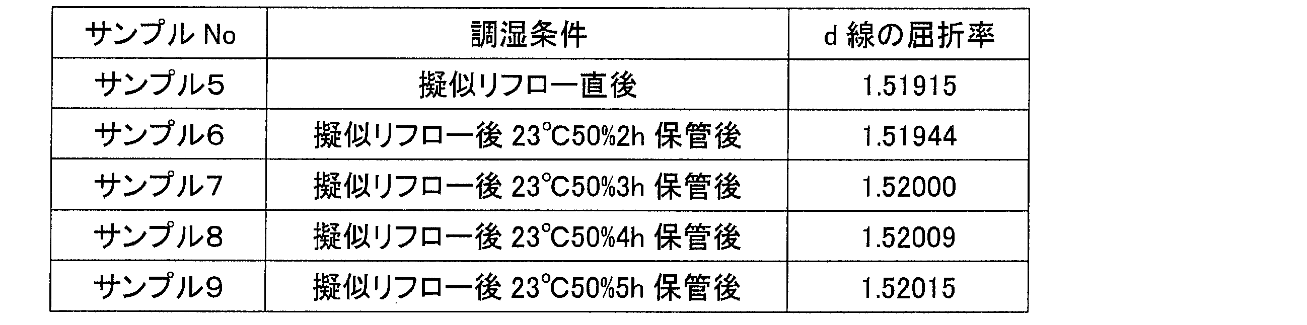
次に、調湿に適した時間の条件を調べるために、サンプル1と同組成の樹脂材料を用い、この樹脂材料に照射量3000mJの紫外線を照射し、その後、加熱装置(真空オーブン)30を用いて200℃、1時間の補助加熱を行って樹脂材料を硬化させ、サンプル5~9を成形した。その後、サンプル5~9を、上記ステップS3に相当する擬似リフロー即ち高温加熱処理として、加熱装置(真空オーブン)30を用いて、260℃で30分間の加熱を行った。直後にサンプル5の屈折率を測定した結果、d線の屈折率が1.51915となった。次に、温度23℃、相対湿度50%に設定の調湿装置40(恒温槽)を用いて、サンプル6を2時間保管して調湿し、サンプル7を3時間保管して調湿し、サンプル8を4時間保管して調湿し、サンプル9を5時間保管して調湿し、それぞれ屈折率を測定した結果、サンプル6のd線の屈折率が1.51944となり、サンプル7のd線の屈折率が1.52000となり、サンプル8のd線の屈折率が1.52009となり、サンプル9のd線の屈折率が1.52015となった。以上から、基準状態を実現する調湿条件として、調湿装置40に3時間以上置くことが望ましいといえる。以下の表1-3は、実験例1-3で得たサンプル5~9の処理内容と屈折率との関係を簡単にまとめたものである。
〔実験例1-4〕
次に、調湿に適した湿度の条件を調べるために、サンプル1と同組成の樹脂材料を用い、この樹脂材料に照射量3000mJの紫外線を照射し、その後、加熱装置(真空オーブン)30を用いて200℃、1時間の補助加熱を行って樹脂材料を硬化させ、サンプル10~16を成形した。その後、サンプル10~16を、上記ステップS3に相当する擬似リフロー即ち高温加熱処理として、加熱装置(真空オーブン)30を用いて、260℃で30分間の加熱を行った。その後、サンプル10を温度23℃、相対湿度20%に設定の調湿装置40に3時間保管して調湿し、屈折率を測定した結果、d線の屈折率が1.51954となった。同様に、サンプル11を温度23℃、相対湿度30%に設定の調湿装置40に3時間保管して調湿し、屈折率を測定した結果、d線の屈折率が1.51971となった。同様に、サンプル12を温度23℃、相対湿度40%に設定の調湿装置40に3時間保管して調湿し、屈折率を測定した結果、d線の屈折率が1.51985となった。同様に、サンプル13を温度23℃、相対湿度50%に設定の調湿装置40に3時間保管して調湿し、屈折率を測定した結果、d線の屈折率が1.52000となった。同様に、サンプル14を温度23℃、相対湿度60%に設定の調湿装置40に3時間保管して調湿し、屈折率を測定した結果、d線の屈折率が1.52014となった。同様に、サンプル15を温度23℃、相対湿度70%に設定の調湿装置40に3時間保管して調湿し、屈折率を測定した結果、d線の屈折率が1.52031となった。同様に、サンプル16を温度23℃、相対湿度80%に設定の調湿装置40に3時間保管して調湿し、屈折率を測定した結果、d線の屈折率が1.52045となった。このように、基準状態を実現する調湿条件として、恒温槽の湿度を50%±30%とする場合は、屈折率が、恒温槽湿度50%のときの屈折率に対して0.00050の範囲に収まっている。以下の表1-4は、実験例1-4で得たサンプル10~16の処理内容と屈折率との関係を簡単にまとめたものである。
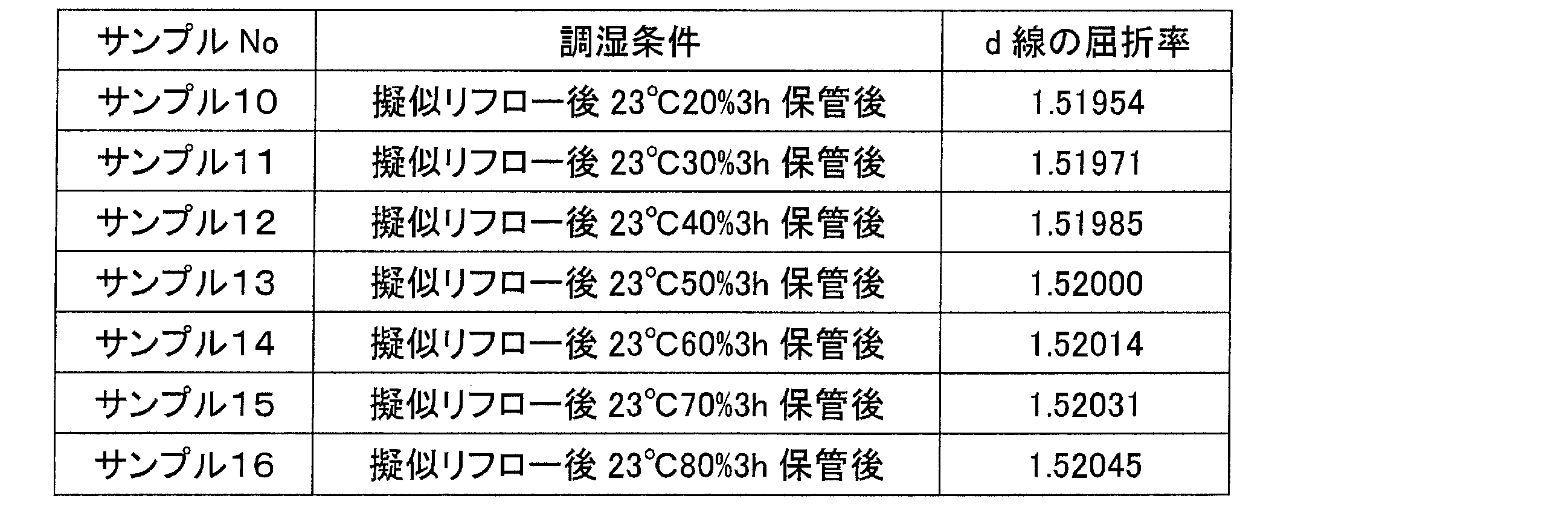
次に、調湿に適した湿度の条件を調べるために、サンプル1と同組成の樹脂材料を用い、この樹脂材料に照射量3000mJの紫外線を照射し、その後、加熱装置(真空オーブン)30を用いて200℃、1時間の補助加熱を行って樹脂材料を硬化させ、サンプル10~16を成形した。その後、サンプル10~16を、上記ステップS3に相当する擬似リフロー即ち高温加熱処理として、加熱装置(真空オーブン)30を用いて、260℃で30分間の加熱を行った。その後、サンプル10を温度23℃、相対湿度20%に設定の調湿装置40に3時間保管して調湿し、屈折率を測定した結果、d線の屈折率が1.51954となった。同様に、サンプル11を温度23℃、相対湿度30%に設定の調湿装置40に3時間保管して調湿し、屈折率を測定した結果、d線の屈折率が1.51971となった。同様に、サンプル12を温度23℃、相対湿度40%に設定の調湿装置40に3時間保管して調湿し、屈折率を測定した結果、d線の屈折率が1.51985となった。同様に、サンプル13を温度23℃、相対湿度50%に設定の調湿装置40に3時間保管して調湿し、屈折率を測定した結果、d線の屈折率が1.52000となった。同様に、サンプル14を温度23℃、相対湿度60%に設定の調湿装置40に3時間保管して調湿し、屈折率を測定した結果、d線の屈折率が1.52014となった。同様に、サンプル15を温度23℃、相対湿度70%に設定の調湿装置40に3時間保管して調湿し、屈折率を測定した結果、d線の屈折率が1.52031となった。同様に、サンプル16を温度23℃、相対湿度80%に設定の調湿装置40に3時間保管して調湿し、屈折率を測定した結果、d線の屈折率が1.52045となった。このように、基準状態を実現する調湿条件として、恒温槽の湿度を50%±30%とする場合は、屈折率が、恒温槽湿度50%のときの屈折率に対して0.00050の範囲に収まっている。以下の表1-4は、実験例1-4で得たサンプル10~16の処理内容と屈折率との関係を簡単にまとめたものである。
〔実験例1-5〕
次に、リフロー前後での屈折率の変動を調べるために、サンプル1と同組成の樹脂材料を用い、この樹脂材料に照射量3000mJの紫外線を照射し、その後、加熱装置(真空オーブン)30を用いて200℃、1時間の補助加熱を行って樹脂材料を硬化させ、サンプル17を成形した。その後、サンプル17を、上記ステップS3に相当する擬似リフロー即ち高温加熱処理として、加熱装置(真空オーブン)30を用いて、260℃で30分間の加熱を行った。その後、サンプル17を、温度23℃、相対湿度50%に設定の調湿装置40(恒温槽)を用いて、3時間保管して調湿した。その後、サンプル17の屈折率を測定した結果、d線の屈折率が1.52000となった。その後、サンプル17をリフロー処理として260℃で10分間加熱し、次いで、サンプル17を、温度23℃、相対湿度50%に設定の調湿装置40(恒温槽)を用いて、3時間保管して調湿した。その後、サンプル17の屈折率を測定した結果、d線の屈折率が1.51982となった。以上から、リフロー前のサンプル17の屈折率と、リフロー後に湿気を吸収したサンプル17の屈折率差は0.00050以内の0.00018となり、屈折率差が十分小さいことがわかる。以下の表1-5は、実験例1-5で得たサンプル17の処理内容と屈折率の関係を簡単にまとめたものである。

次に、リフロー前後での屈折率の変動を調べるために、サンプル1と同組成の樹脂材料を用い、この樹脂材料に照射量3000mJの紫外線を照射し、その後、加熱装置(真空オーブン)30を用いて200℃、1時間の補助加熱を行って樹脂材料を硬化させ、サンプル17を成形した。その後、サンプル17を、上記ステップS3に相当する擬似リフロー即ち高温加熱処理として、加熱装置(真空オーブン)30を用いて、260℃で30分間の加熱を行った。その後、サンプル17を、温度23℃、相対湿度50%に設定の調湿装置40(恒温槽)を用いて、3時間保管して調湿した。その後、サンプル17の屈折率を測定した結果、d線の屈折率が1.52000となった。その後、サンプル17をリフロー処理として260℃で10分間加熱し、次いで、サンプル17を、温度23℃、相対湿度50%に設定の調湿装置40(恒温槽)を用いて、3時間保管して調湿した。その後、サンプル17の屈折率を測定した結果、d線の屈折率が1.51982となった。以上から、リフロー前のサンプル17の屈折率と、リフロー後に湿気を吸収したサンプル17の屈折率差は0.00050以内の0.00018となり、屈折率差が十分小さいことがわかる。以下の表1-5は、実験例1-5で得たサンプル17の処理内容と屈折率の関係を簡単にまとめたものである。
〔実験例1-6〕
次に、梱包に適した素材の透水について調べるために、サンプル1と同組成の樹脂材料を用い、この樹脂材料に照射量3000mJの紫外線を照射し、その後、加熱装置(真空オーブン)30を用いて200℃、1時間の補助加熱を行って樹脂材料を硬化させ、サンプル18~20を成形した。その後、サンプル18~20を、上記ステップS3に相当する擬似リフロー即ち高温加熱処理として、加熱装置(真空オーブン)30を用いて、260℃で30分間の加熱を行った。その後、サンプル18~20を、温度23℃、相対湿度50%に設定の調湿装置40(恒温槽)を用いて、3時間保管して調湿した。その後、サンプル18を透水度10g/m2・24hの素材で梱包し、温度23℃、相対湿度90%に設定の調湿装置40に48時間保管して調湿し、屈折率を測定した結果、d線の屈折率が1.52008となった。同様に、調湿処理後のサンプル19を透水度15g/m2・24hの素材で梱包し、温度23℃、相対湿度90%に設定の調湿装置40に48時間保管して調湿し、屈折率を測定した結果、d線の屈折率が1.52022となった。同様に、調湿処理後のサンプル20を透水度20g/m2・24hの素材で梱包し、温度23℃、相対湿度90%に設定の調湿装置40に48時間保管して調湿し、屈折率を測定した結果、d線の屈折率が1.52039となった。このように、梱包工程において、梱包材として透水度20g/m2・24h以下の素材を用いる場合は、屈折率の変化が0.00050以内に収まっている。以下の表1-6は、実験例1-6で得たサンプル18~20を梱包した素材の透水度と、サンプル18~20の屈折率の関係を簡単にまとめたものである。

次に、梱包に適した素材の透水について調べるために、サンプル1と同組成の樹脂材料を用い、この樹脂材料に照射量3000mJの紫外線を照射し、その後、加熱装置(真空オーブン)30を用いて200℃、1時間の補助加熱を行って樹脂材料を硬化させ、サンプル18~20を成形した。その後、サンプル18~20を、上記ステップS3に相当する擬似リフロー即ち高温加熱処理として、加熱装置(真空オーブン)30を用いて、260℃で30分間の加熱を行った。その後、サンプル18~20を、温度23℃、相対湿度50%に設定の調湿装置40(恒温槽)を用いて、3時間保管して調湿した。その後、サンプル18を透水度10g/m2・24hの素材で梱包し、温度23℃、相対湿度90%に設定の調湿装置40に48時間保管して調湿し、屈折率を測定した結果、d線の屈折率が1.52008となった。同様に、調湿処理後のサンプル19を透水度15g/m2・24hの素材で梱包し、温度23℃、相対湿度90%に設定の調湿装置40に48時間保管して調湿し、屈折率を測定した結果、d線の屈折率が1.52022となった。同様に、調湿処理後のサンプル20を透水度20g/m2・24hの素材で梱包し、温度23℃、相対湿度90%に設定の調湿装置40に48時間保管して調湿し、屈折率を測定した結果、d線の屈折率が1.52039となった。このように、梱包工程において、梱包材として透水度20g/m2・24h以下の素材を用いる場合は、屈折率の変化が0.00050以内に収まっている。以下の表1-6は、実験例1-6で得たサンプル18~20を梱包した素材の透水度と、サンプル18~20の屈折率の関係を簡単にまとめたものである。
〔実験例1-7〕
次に、樹脂の環境変動に対する耐性を調べるために、サンプル1と同組成の樹脂材料を用い、この樹脂材料に照射量3000mJの紫外線を照射し、その後、加熱装置(真空オーブン)30を用いて200℃、1時間の補助加熱を行って樹脂材料を硬化させ、サンプル21を成形した。その後、サンプル21を、上記ステップS3に相当する擬似リフロー即ち高温加熱処理として、加熱装置(真空オーブン)30を用いて、260℃で30分間の加熱を行った。直後にサンプル21の屈折率を測定した結果、d線の屈折率が1.51915となった。その後、サンプル21を、温度23℃、相対湿度50%に設定の調湿装置40(恒温槽)を用いて、3時間保管して調湿した。その後、サンプル21の屈折率を測定した結果、d線の屈折率が1.52000となった。その後、サンプル21を、温度60℃、相対湿度90%に設定の調湿装置40(恒温槽)を用いて、168時間保管した。その後、サンプル21の屈折率を測定した結果、d線の屈折率が1.52068となった。その後、サンプル21を、温度23℃、相対湿度50%に設定の調湿装置40(恒温槽)を用いて、3時間保管して調湿した。その後、サンプル21の屈折率を測定した結果、d線の屈折率が1.52002となった。その後、サンプル21を、温度85℃、相対湿度0%に設定の調湿装置40(恒温槽)を用いて、168時間保管して調湿した。その後、サンプル21の屈折率を測定した結果、d線の屈折率が1.51918となった。その後、サンプル21を、温度23℃、相対湿度50%に設定の調湿装置40(恒温槽)を用いて、3時間保管して調湿した。その後、サンプル21の屈折率を測定した結果、d線の屈折率が1.51998となった。このように、光学素子を高温高湿環境下に長時間曝すと屈折率が上昇するものの調湿工程を経ることで、屈折率が疑似リフロー処理後の調湿処理後の値にほぼ戻り、また、光学素子を高温低湿環境下に長時間曝すと屈折率が低下するものの調湿工程を経ることで、屈折率が疑似リフロー処理後の調湿処理後の値にほぼ戻ることが理解される。以下の表1-7は、実験例1-7で得たサンプル21の処理内容と屈折率との関係を簡単にまとめたものである。
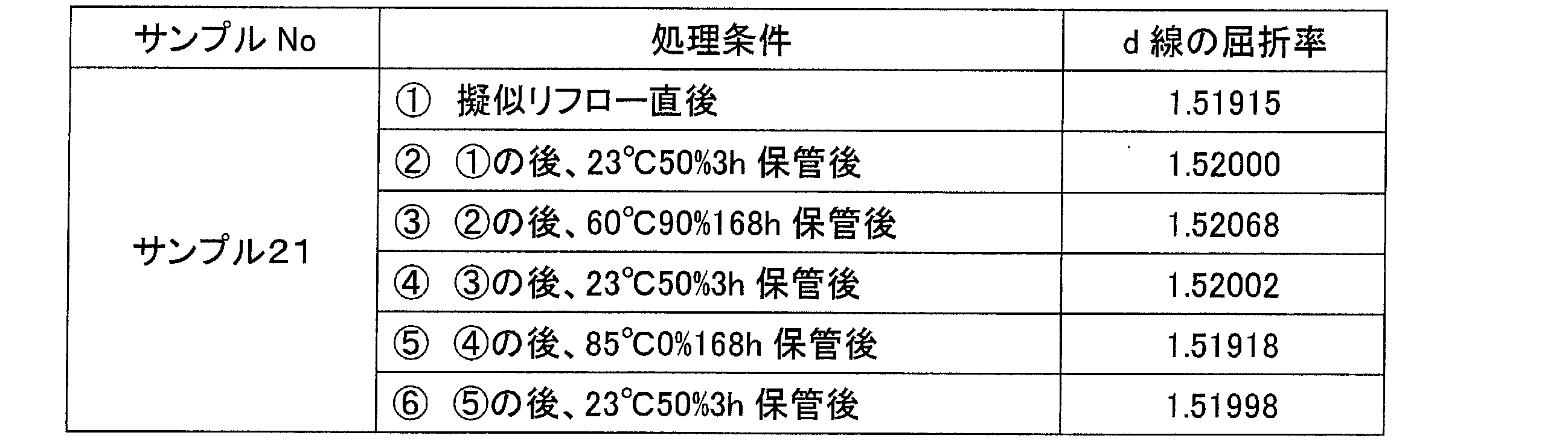
次に、樹脂の環境変動に対する耐性を調べるために、サンプル1と同組成の樹脂材料を用い、この樹脂材料に照射量3000mJの紫外線を照射し、その後、加熱装置(真空オーブン)30を用いて200℃、1時間の補助加熱を行って樹脂材料を硬化させ、サンプル21を成形した。その後、サンプル21を、上記ステップS3に相当する擬似リフロー即ち高温加熱処理として、加熱装置(真空オーブン)30を用いて、260℃で30分間の加熱を行った。直後にサンプル21の屈折率を測定した結果、d線の屈折率が1.51915となった。その後、サンプル21を、温度23℃、相対湿度50%に設定の調湿装置40(恒温槽)を用いて、3時間保管して調湿した。その後、サンプル21の屈折率を測定した結果、d線の屈折率が1.52000となった。その後、サンプル21を、温度60℃、相対湿度90%に設定の調湿装置40(恒温槽)を用いて、168時間保管した。その後、サンプル21の屈折率を測定した結果、d線の屈折率が1.52068となった。その後、サンプル21を、温度23℃、相対湿度50%に設定の調湿装置40(恒温槽)を用いて、3時間保管して調湿した。その後、サンプル21の屈折率を測定した結果、d線の屈折率が1.52002となった。その後、サンプル21を、温度85℃、相対湿度0%に設定の調湿装置40(恒温槽)を用いて、168時間保管して調湿した。その後、サンプル21の屈折率を測定した結果、d線の屈折率が1.51918となった。その後、サンプル21を、温度23℃、相対湿度50%に設定の調湿装置40(恒温槽)を用いて、3時間保管して調湿した。その後、サンプル21の屈折率を測定した結果、d線の屈折率が1.51998となった。このように、光学素子を高温高湿環境下に長時間曝すと屈折率が上昇するものの調湿工程を経ることで、屈折率が疑似リフロー処理後の調湿処理後の値にほぼ戻り、また、光学素子を高温低湿環境下に長時間曝すと屈折率が低下するものの調湿工程を経ることで、屈折率が疑似リフロー処理後の調湿処理後の値にほぼ戻ることが理解される。以下の表1-7は、実験例1-7で得たサンプル21の処理内容と屈折率との関係を簡単にまとめたものである。
〔実験例2-1〕
実験例2-1では、レンズユニット10の樹脂層102を得るための樹脂材料として、アクリル系の紫外線硬化性樹脂材料を用いて各種の測定を行った。ここでは、紫外線硬化型アクリル系樹脂材料として、2-アルキル-2-アダマンチル(メタ)アクリレートに対し、UV硬化開始剤としてチバスペシャリティケミカルズ社製IRGACURE907を1wt%添加したものを用いている。
実験例2-1では、レンズユニット10の樹脂層102を得るための樹脂材料として、アクリル系の紫外線硬化性樹脂材料を用いて各種の測定を行った。ここでは、紫外線硬化型アクリル系樹脂材料として、2-アルキル-2-アダマンチル(メタ)アクリレートに対し、UV硬化開始剤としてチバスペシャリティケミカルズ社製IRGACURE907を1wt%添加したものを用いている。
まず、高温加熱工程の有無による屈折率の変化を調べるために、この樹脂材料に照射量1800mJの紫外線を照射し、その後、加熱装置(真空オーブン)30を用いて150℃、1時間の補助加熱を行って樹脂材料を硬化させ、サンプル22~23を成形した。その後、サンプル22を基準状態とするために、温度23℃、相対湿度50%に設定の調湿装置40(恒温槽)でサンプル22を3時間保管して調湿し、屈折率を測定した結果、d線の屈折率が1.60090となった。次にサンプル23を、上記ステップS3に相当する擬似リフロー即ち高温加熱処理として、加熱装置(真空オーブン)30を用いて、260℃で30分間の加熱を行った。その後、サンプル23を基準状態とするために、温度23℃、相対湿度50%に設定の調湿装置40(恒温槽)でサンプル23を3時間保管して調湿し、屈折率を測定した結果、d線の屈折率が1.60000となった。サンプル22~23の屈折率を比較すると、その差は0.00050以上の0.00090であり、高温加熱処理を行っていないサンプル22の方が屈折率が高い結果となった。この結果から、高温加熱処理前に通常行われる程度の補助加熱処理による効果のみではサンプル22を構成する樹脂の硬化具合が十分でなかったことがわかる。これに対して、高温加熱処理を行うことで、サンプル23の屈折率が低下し、硬化が進んだことがわかる。以下の表2-1は、実験例2-1で得たサンプル22~23の処理内容と屈折率との関係を簡単にまとめたものである。

〔実験例2-2〕
次に、吸水の影響を調べるために、サンプル22と同組成の樹脂材料を用い、この樹脂材料に照射量1800mJの紫外線を照射し、その後、加熱装置(真空オーブン)30を用いて150℃、1時間の補助加熱を行って樹脂材料を硬化させ、サンプル24~25を成形した。その後、サンプル24~25を、上記ステップS3に相当する擬似リフロー即ち高温加熱処理として、加熱装置(真空オーブン)30を用いて、260℃で30分間の加熱を行った。直後にサンプル24の屈折率を測定した結果、d線の屈折率が1.59905となった。次に、サンプル25を温度85℃、相対湿度85%に設定の調湿装置(恒温槽)40で2日間保管して樹脂を飽和吸水させた後、サンプル25の屈折率を測定した結果、d線の屈折率が1.60085となった。樹脂が十分に乾燥しているサンプル24と、樹脂が十分に吸水している状態のサンプル25の屈折率とを比較すると、その差は0.00100以上の0.00180であり、吸水による屈折率変化の大きい樹脂であることがわかる。以下の表2-2は、実験例2-2で得たサンプル24~25の処理内容と屈折率との関係を簡単にまとめたものである。

次に、吸水の影響を調べるために、サンプル22と同組成の樹脂材料を用い、この樹脂材料に照射量1800mJの紫外線を照射し、その後、加熱装置(真空オーブン)30を用いて150℃、1時間の補助加熱を行って樹脂材料を硬化させ、サンプル24~25を成形した。その後、サンプル24~25を、上記ステップS3に相当する擬似リフロー即ち高温加熱処理として、加熱装置(真空オーブン)30を用いて、260℃で30分間の加熱を行った。直後にサンプル24の屈折率を測定した結果、d線の屈折率が1.59905となった。次に、サンプル25を温度85℃、相対湿度85%に設定の調湿装置(恒温槽)40で2日間保管して樹脂を飽和吸水させた後、サンプル25の屈折率を測定した結果、d線の屈折率が1.60085となった。樹脂が十分に乾燥しているサンプル24と、樹脂が十分に吸水している状態のサンプル25の屈折率とを比較すると、その差は0.00100以上の0.00180であり、吸水による屈折率変化の大きい樹脂であることがわかる。以下の表2-2は、実験例2-2で得たサンプル24~25の処理内容と屈折率との関係を簡単にまとめたものである。
〔実験例2-3〕
次に、調湿に適した時間の条件を調べるために、サンプル22と同組成の樹脂材料を用い、この樹脂材料に照射量1800mJの紫外線を照射し、その後、加熱装置(真空オーブン)30を用いて150℃、1時間の補助加熱を行って樹脂材料を硬化させ、サンプル26~30を成形した。その後、サンプル26~30を、上記ステップS3に相当する擬似リフロー即ち高温加熱処理として、加熱装置(真空オーブン)30を用いて、260℃で30分間の加熱を行った。直後にサンプル26の屈折率を測定した結果、d線の屈折率が1.59905となった。次に、温度23℃、相対湿度50%設定の調湿装置40(恒温槽)を用いて、サンプル27を2時間保管して調湿し、サンプル28を3時間保管して調湿し、サンプル29を4時間保管して調湿し、サンプル30を5時間保管して調湿し、それぞれ屈折率を測定した結果、サンプル27のd線の屈折率が1.59942となり、サンプル28のd線の屈折率が1.60000となり、サンプル29のd線の屈折率が1.60011となり、サンプル30のd線の屈折率が1.60018となった。以上から、基準状態を実現する調湿条件として、調湿装置40に3時間以上置くことが望ましいといえる。以下の表2-3は、実験例2-3で得たサンプル26~30の処理内容と屈折率との関係を簡単にまとめたものである。
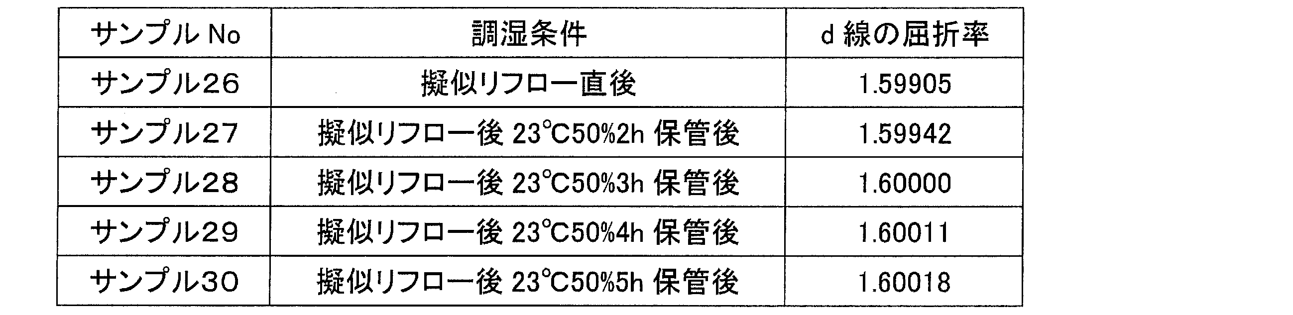
次に、調湿に適した時間の条件を調べるために、サンプル22と同組成の樹脂材料を用い、この樹脂材料に照射量1800mJの紫外線を照射し、その後、加熱装置(真空オーブン)30を用いて150℃、1時間の補助加熱を行って樹脂材料を硬化させ、サンプル26~30を成形した。その後、サンプル26~30を、上記ステップS3に相当する擬似リフロー即ち高温加熱処理として、加熱装置(真空オーブン)30を用いて、260℃で30分間の加熱を行った。直後にサンプル26の屈折率を測定した結果、d線の屈折率が1.59905となった。次に、温度23℃、相対湿度50%設定の調湿装置40(恒温槽)を用いて、サンプル27を2時間保管して調湿し、サンプル28を3時間保管して調湿し、サンプル29を4時間保管して調湿し、サンプル30を5時間保管して調湿し、それぞれ屈折率を測定した結果、サンプル27のd線の屈折率が1.59942となり、サンプル28のd線の屈折率が1.60000となり、サンプル29のd線の屈折率が1.60011となり、サンプル30のd線の屈折率が1.60018となった。以上から、基準状態を実現する調湿条件として、調湿装置40に3時間以上置くことが望ましいといえる。以下の表2-3は、実験例2-3で得たサンプル26~30の処理内容と屈折率との関係を簡単にまとめたものである。
〔実験例2-4〕
次に、調湿に適した湿度の条件を調べるために、サンプル22と同組成の樹脂材料を用い、この樹脂材料に照射量1800mJの紫外線を照射し、その後、加熱装置(真空オーブン)30を用いて150℃、1時間の補助加熱を行って樹脂材料を硬化させ、サンプル31~37を成形した。その後、サンプル31~37を、上記ステップS3に相当する擬似リフロー即ち高温加熱処理として、加熱装置(真空オーブン)30を用いて、260℃で30分間の加熱を行った。その後、サンプル31を温度23℃、相対湿度20%に設定の調湿装置40に3時間保管して調湿し、屈折率を測定した結果、d線の屈折率が1.59952となった。同様に、サンプル32を温度23℃、相対湿度30%に設定の調湿装置40に3時間保管して調湿し、屈折率を測定した結果、d線の屈折率が1.59969となった。同様に、サンプル33を温度23℃、相対湿度40%に設定の調湿装置40に3時間保管して調湿し、屈折率を測定した結果、d線の屈折率が1.59984となった。同様に、サンプル34を温度23℃、相対湿度50%に設定の調湿装置40に3時間保管して調湿し、屈折率を測定した結果、d線の屈折率が1.60000となった。同様に、サンプル35を温度23℃、相対湿度60%に設定の調湿装置40に3時間保管して調湿し、屈折率を測定した結果、d線の屈折率が1.60015となった。同様に、サンプル36を温度23℃、相対湿度70%に設定の調湿装置40に3時間保管して調湿し、屈折率を測定した結果、d線の屈折率が1.60033となった。同様に、サンプル37を温度23℃、相対湿度80%に設定の調湿装置40に3時間保管して調湿し、屈折率を測定した結果、d線の屈折率が1.60048となった。このように、基準状態を実現する調湿条件として、恒温槽の湿度を50%±30%とする場合は、屈折率が、恒温槽湿度50%のときの屈折率に対して0.00050の範囲に収まっている。以下の表2-4は、実験例2-4で得たサンプル31~37の処理内容と屈折率との関係を簡単にまとめたものである。

次に、調湿に適した湿度の条件を調べるために、サンプル22と同組成の樹脂材料を用い、この樹脂材料に照射量1800mJの紫外線を照射し、その後、加熱装置(真空オーブン)30を用いて150℃、1時間の補助加熱を行って樹脂材料を硬化させ、サンプル31~37を成形した。その後、サンプル31~37を、上記ステップS3に相当する擬似リフロー即ち高温加熱処理として、加熱装置(真空オーブン)30を用いて、260℃で30分間の加熱を行った。その後、サンプル31を温度23℃、相対湿度20%に設定の調湿装置40に3時間保管して調湿し、屈折率を測定した結果、d線の屈折率が1.59952となった。同様に、サンプル32を温度23℃、相対湿度30%に設定の調湿装置40に3時間保管して調湿し、屈折率を測定した結果、d線の屈折率が1.59969となった。同様に、サンプル33を温度23℃、相対湿度40%に設定の調湿装置40に3時間保管して調湿し、屈折率を測定した結果、d線の屈折率が1.59984となった。同様に、サンプル34を温度23℃、相対湿度50%に設定の調湿装置40に3時間保管して調湿し、屈折率を測定した結果、d線の屈折率が1.60000となった。同様に、サンプル35を温度23℃、相対湿度60%に設定の調湿装置40に3時間保管して調湿し、屈折率を測定した結果、d線の屈折率が1.60015となった。同様に、サンプル36を温度23℃、相対湿度70%に設定の調湿装置40に3時間保管して調湿し、屈折率を測定した結果、d線の屈折率が1.60033となった。同様に、サンプル37を温度23℃、相対湿度80%に設定の調湿装置40に3時間保管して調湿し、屈折率を測定した結果、d線の屈折率が1.60048となった。このように、基準状態を実現する調湿条件として、恒温槽の湿度を50%±30%とする場合は、屈折率が、恒温槽湿度50%のときの屈折率に対して0.00050の範囲に収まっている。以下の表2-4は、実験例2-4で得たサンプル31~37の処理内容と屈折率との関係を簡単にまとめたものである。
〔実験例2-5〕
次に、リフロー前後での屈折率の変動を調べるために、サンプル22と同組成の樹脂材料を用い、この樹脂に照射量1800mJの紫外線を照射し、その後、加熱装置(真空オーブン)30を用いて150℃、1時間の補助加熱を行って樹脂材料を硬化させ、サンプル38を成形した。その後、サンプル38を、上記ステップS3に相当する擬似リフロー即ち高温加熱処理として、加熱装置(真空オーブン)30を用いて、260℃で30分間の加熱を行った。その後、サンプル38を、温度23℃、相対湿度50%に設定の調湿装置40(恒温槽)を用いて、3時間保管して調湿した。その後、サンプル38の屈折率を測定した結果、d線の屈折率が1.60000となった。その後、サンプル38をリフロー処理として260℃で10分間加熱し、次いで、サンプル38を、温度23℃、相対湿度50%に設定の調湿装置40(恒温槽)を用いて、3時間保管して調湿した。その後、サンプル38の屈折率を測定した結果、d線の屈折率が1.59980となった。以上から、リフロー前のサンプル38の屈折率と、リフロー後に湿気を吸収したサンプル38の屈折率差は0.00050以内の0.00020となり、屈折率差が十分小さいことがわかる。以下の表2-5は、実験例2-5で得たサンプル38の処理内容と屈折率の関係を簡単にまとめたものである。

次に、リフロー前後での屈折率の変動を調べるために、サンプル22と同組成の樹脂材料を用い、この樹脂に照射量1800mJの紫外線を照射し、その後、加熱装置(真空オーブン)30を用いて150℃、1時間の補助加熱を行って樹脂材料を硬化させ、サンプル38を成形した。その後、サンプル38を、上記ステップS3に相当する擬似リフロー即ち高温加熱処理として、加熱装置(真空オーブン)30を用いて、260℃で30分間の加熱を行った。その後、サンプル38を、温度23℃、相対湿度50%に設定の調湿装置40(恒温槽)を用いて、3時間保管して調湿した。その後、サンプル38の屈折率を測定した結果、d線の屈折率が1.60000となった。その後、サンプル38をリフロー処理として260℃で10分間加熱し、次いで、サンプル38を、温度23℃、相対湿度50%に設定の調湿装置40(恒温槽)を用いて、3時間保管して調湿した。その後、サンプル38の屈折率を測定した結果、d線の屈折率が1.59980となった。以上から、リフロー前のサンプル38の屈折率と、リフロー後に湿気を吸収したサンプル38の屈折率差は0.00050以内の0.00020となり、屈折率差が十分小さいことがわかる。以下の表2-5は、実験例2-5で得たサンプル38の処理内容と屈折率の関係を簡単にまとめたものである。
〔実験例2-6〕
次に、梱包に適した素材の透水について調べるために、サンプル22と同組成の樹脂材料を用い、この樹脂材料に照射量1800mJの紫外線を照射し、その後、加熱装置(真空オーブン)30を用いて150℃、1時間の補助加熱を行って樹脂材料を硬化させ、サンプル39~41を成形した。その後、サンプル39~41を、上記ステップS3に相当する擬似リフロー即ち高温加熱処理として、加熱装置(真空オーブン)30を用いて、260℃で30分間の加熱を行った。その後、サンプル39~41を、温度23℃、相対湿度50%に設定の調湿装置40(恒温槽)を用いて、3時間保管して調湿した。その後、サンプル39を透水度10g/m2・24hの素材で梱包し、温度23℃、相対湿度90%に設定の調湿装置40に48時間保管して調湿し、屈折率を測定した結果、d線の屈折率が1.60009となった。同様に、調湿処理後のサンプル40を透水度15g/m2・24hの素材で梱包し、温度23℃、相対湿度90%に設定の調湿装置40に48時間保管して調湿し、屈折率を測定した結果、d線の屈折率が1.60025となった。同様に、調湿処理後のサンプル41を透水度20g/m2・24hの素材で梱包し、温度23℃、相対湿度90%に設定の調湿装置40に48時間保管して調湿し、屈折率を測定した結果、d線の屈折率が1.60041となった。このように、梱包工程において、梱包材として透水度20g/m2・24h以下の素材を用いる場合は、屈折率の変化が0.00050以内に収まっている。以下の表2-6は、実験例2-6で得たサンプル39~41を梱包した素材の透水度と、サンプル39~41の屈折率の関係を簡単にまとめたものである。

次に、梱包に適した素材の透水について調べるために、サンプル22と同組成の樹脂材料を用い、この樹脂材料に照射量1800mJの紫外線を照射し、その後、加熱装置(真空オーブン)30を用いて150℃、1時間の補助加熱を行って樹脂材料を硬化させ、サンプル39~41を成形した。その後、サンプル39~41を、上記ステップS3に相当する擬似リフロー即ち高温加熱処理として、加熱装置(真空オーブン)30を用いて、260℃で30分間の加熱を行った。その後、サンプル39~41を、温度23℃、相対湿度50%に設定の調湿装置40(恒温槽)を用いて、3時間保管して調湿した。その後、サンプル39を透水度10g/m2・24hの素材で梱包し、温度23℃、相対湿度90%に設定の調湿装置40に48時間保管して調湿し、屈折率を測定した結果、d線の屈折率が1.60009となった。同様に、調湿処理後のサンプル40を透水度15g/m2・24hの素材で梱包し、温度23℃、相対湿度90%に設定の調湿装置40に48時間保管して調湿し、屈折率を測定した結果、d線の屈折率が1.60025となった。同様に、調湿処理後のサンプル41を透水度20g/m2・24hの素材で梱包し、温度23℃、相対湿度90%に設定の調湿装置40に48時間保管して調湿し、屈折率を測定した結果、d線の屈折率が1.60041となった。このように、梱包工程において、梱包材として透水度20g/m2・24h以下の素材を用いる場合は、屈折率の変化が0.00050以内に収まっている。以下の表2-6は、実験例2-6で得たサンプル39~41を梱包した素材の透水度と、サンプル39~41の屈折率の関係を簡単にまとめたものである。
〔実験例2-7〕
次に、樹脂の環境変動に対する耐性を調べるために、サンプル22と同組成の樹脂材料を用い、この樹脂材料に照射量1800mJの紫外線を照射し、その後、加熱装置(真空オーブン)30を用いて150℃、1時間の補助加熱を行って樹脂材料を硬化させ、サンプル42を成形した。その後、サンプル42を、上記ステップS3に相当する擬似リフロー即ち高温加熱処理として、加熱装置(真空オーブン)30を用いて、260℃で30分間の加熱を行った。直後にサンプル42の屈折率を測定した結果、d線の屈折率が1.59905となった。その後、サンプル42を、温度23℃、相対湿度50%に設定の調湿装置40(恒温槽)を用いて、3時間保管して調湿した。その後、サンプル42の屈折率を測定した結果、d線の屈折率が1.60000となった。その後、サンプル42を、温度60℃、相対湿度90%に設定の調湿装置40(恒温槽)を用いて、168時間保管した。その後、サンプル42の屈折率を測定した結果、d線の屈折率が1.60071となった。その後、サンプル42を、温度23℃、相対湿度50%に設定の調湿装置40(恒温槽)を用いて、3時間保管して調湿した。その後、サンプル42の屈折率を測定した結果、d線の屈折率が1.60001となった。その後、サンプル42を、温度85℃、相対湿度0%に設定の調湿装置40(恒温槽)を用いて、168時間保管して調湿した。その後、サンプル42の屈折率を測定した結果、d線の屈折率が1.59915となった。その後、サンプル42を、温度23℃、相対湿度50%に設定の調湿装置40(恒温槽)を用いて、3時間保管して調湿した。その後、サンプル42の屈折率を測定した結果、d線の屈折率が1.59997となった。このように、光学素子を高温高湿環境下に長時間曝すと屈折率が上昇するものの調湿工程を経ることで、屈折率が疑似リフロー処理後の調湿処理後の値にほぼ戻り、また、光学素子を高温低湿環境下に長時間曝すと屈折率が低下するものの調湿工程を経ることで、屈折率が疑似リフロー処理後の調湿処理後の値にほぼ戻ることが理解される。以下の表2-7は、実験例2-7で得たサンプル42の処理内容と屈折率との関係を簡単にまとめたものである。

次に、樹脂の環境変動に対する耐性を調べるために、サンプル22と同組成の樹脂材料を用い、この樹脂材料に照射量1800mJの紫外線を照射し、その後、加熱装置(真空オーブン)30を用いて150℃、1時間の補助加熱を行って樹脂材料を硬化させ、サンプル42を成形した。その後、サンプル42を、上記ステップS3に相当する擬似リフロー即ち高温加熱処理として、加熱装置(真空オーブン)30を用いて、260℃で30分間の加熱を行った。直後にサンプル42の屈折率を測定した結果、d線の屈折率が1.59905となった。その後、サンプル42を、温度23℃、相対湿度50%に設定の調湿装置40(恒温槽)を用いて、3時間保管して調湿した。その後、サンプル42の屈折率を測定した結果、d線の屈折率が1.60000となった。その後、サンプル42を、温度60℃、相対湿度90%に設定の調湿装置40(恒温槽)を用いて、168時間保管した。その後、サンプル42の屈折率を測定した結果、d線の屈折率が1.60071となった。その後、サンプル42を、温度23℃、相対湿度50%に設定の調湿装置40(恒温槽)を用いて、3時間保管して調湿した。その後、サンプル42の屈折率を測定した結果、d線の屈折率が1.60001となった。その後、サンプル42を、温度85℃、相対湿度0%に設定の調湿装置40(恒温槽)を用いて、168時間保管して調湿した。その後、サンプル42の屈折率を測定した結果、d線の屈折率が1.59915となった。その後、サンプル42を、温度23℃、相対湿度50%に設定の調湿装置40(恒温槽)を用いて、3時間保管して調湿した。その後、サンプル42の屈折率を測定した結果、d線の屈折率が1.59997となった。このように、光学素子を高温高湿環境下に長時間曝すと屈折率が上昇するものの調湿工程を経ることで、屈折率が疑似リフロー処理後の調湿処理後の値にほぼ戻り、また、光学素子を高温低湿環境下に長時間曝すと屈折率が低下するものの調湿工程を経ることで、屈折率が疑似リフロー処理後の調湿処理後の値にほぼ戻ることが理解される。以下の表2-7は、実験例2-7で得たサンプル42の処理内容と屈折率との関係を簡単にまとめたものである。
〔実験例3-1〕
実験例3-1では、レンズユニット10の樹脂層102を得るための樹脂材料として、アリルエステル系の紫外線硬化性樹脂材料を用いて各種の測定を行った。ここでは、紫外線硬化型アリルエステル系樹脂材料として、芳香環を含まない臭素含有(メタ)アリルエステル(特開2003-66201号公報参照)に対し、UV硬化開始剤としてチバスペシャリティケミカルズ社製IRGACURE907を1wt%添加したものを用いている。
実験例3-1では、レンズユニット10の樹脂層102を得るための樹脂材料として、アリルエステル系の紫外線硬化性樹脂材料を用いて各種の測定を行った。ここでは、紫外線硬化型アリルエステル系樹脂材料として、芳香環を含まない臭素含有(メタ)アリルエステル(特開2003-66201号公報参照)に対し、UV硬化開始剤としてチバスペシャリティケミカルズ社製IRGACURE907を1wt%添加したものを用いている。
まず、高温加熱工程の有無による屈折率の変化を調べるために、この樹脂材料に照射量6000mJの紫外線を照射し、その後、加熱装置(真空オーブン)30を用いて150℃、2時間の補助加熱を行って樹脂材料を硬化させ、サンプル43~44を成形した。その後、サンプル43を基準状態とするために、温度23℃、相対湿度50%に設定の調湿装置40(恒温槽)でサンプル43を3時間保管して調湿し、屈折率を測定した結果、d線の屈折率が1.58635となった。次にサンプル44を、上記ステップS3に相当する擬似リフロー即ち高温加熱処理として、加熱装置(真空オーブン)30を用いて、260℃で30分間の加熱を行った。その後、サンプル44を基準状態とするために、温度23℃、相対湿度50%に設定の調湿装置40(恒温槽)でサンプル44を3時間保管して調湿し、屈折率を測定した結果、d線の屈折率が1.58550となった。サンプル43~44の屈折率を比較すると、その差は0.00050以上の0.00085であり、高温加熱処理を行っていないサンプル43の方が屈折率が高い結果となった。この結果から、高温加熱処理前に通常行われる程度の補助加熱処理による効果のみではサンプル43を構成する樹脂の硬化具合が十分でなかったことがわかる。これに対して、高温加熱処理を行うことで、サンプル44の屈折率が低下し、硬化が進んだことがわかる。以下の表3-1は、実験例3-1で得たサンプル43~44の処理内容と屈折率との関係を簡単にまとめたものである。

〔実験例3-2〕
次に、吸水の影響を調べるために、サンプル43と同組成の樹脂材料を用い、この樹脂材料に照射量6000mJの紫外線を照射し、その後、加熱装置(真空オーブン)30を用いて150℃、2時間の補助加熱を行って樹脂材料を硬化させ、サンプル45~46を成形した。その後、サンプル45~46を、上記ステップS3に相当する擬似リフロー即ち高温加熱処理として、加熱装置(真空オーブン)30を用いて、260℃で30分間の加熱を行った。直後にサンプル45の屈折率を測定した結果、d線の屈折率が1.58460となった。次に、サンプル46を温度85℃、相対湿度85%に設定の調湿装置(恒温槽)40で2日間保管して樹脂を飽和吸水させた後、サンプル46の屈折率を測定した結果、d線の屈折率が1.58630となった。樹脂が十分に乾燥しているサンプル45と、樹脂が十分に吸水している状態のサンプル46の屈折率とを比較すると、その差は0.00100以上の0.00170であり、吸水による屈折率変化の大きい樹脂であることがわかる。以下の表3-2は、実験例3-2で得たサンプル45~46の処理内容と屈折率との関係を簡単にまとめたものである。

次に、吸水の影響を調べるために、サンプル43と同組成の樹脂材料を用い、この樹脂材料に照射量6000mJの紫外線を照射し、その後、加熱装置(真空オーブン)30を用いて150℃、2時間の補助加熱を行って樹脂材料を硬化させ、サンプル45~46を成形した。その後、サンプル45~46を、上記ステップS3に相当する擬似リフロー即ち高温加熱処理として、加熱装置(真空オーブン)30を用いて、260℃で30分間の加熱を行った。直後にサンプル45の屈折率を測定した結果、d線の屈折率が1.58460となった。次に、サンプル46を温度85℃、相対湿度85%に設定の調湿装置(恒温槽)40で2日間保管して樹脂を飽和吸水させた後、サンプル46の屈折率を測定した結果、d線の屈折率が1.58630となった。樹脂が十分に乾燥しているサンプル45と、樹脂が十分に吸水している状態のサンプル46の屈折率とを比較すると、その差は0.00100以上の0.00170であり、吸水による屈折率変化の大きい樹脂であることがわかる。以下の表3-2は、実験例3-2で得たサンプル45~46の処理内容と屈折率との関係を簡単にまとめたものである。
〔実験例3-3〕
次に、調湿に適した時間の条件を調べるために、サンプル43と同組成の樹脂材料を用い、この樹脂材料に照射量6000mJの紫外線を照射し、その後、加熱装置(真空オーブン)30を用いて150℃、2時間の補助加熱を行って樹脂材料を硬化させ、サンプル47~51を成形した。その後、サンプル47~51を、上記ステップS3に相当する擬似リフロー即ち高温加熱処理として、加熱装置(真空オーブン)30を用いて、260℃で30分間の加熱を行った。直後にサンプル47の屈折率を測定した結果、d線の屈折率が1.58460となった。次に、温度23℃、相対湿度50%に設定の調湿装置40(恒温槽)を用いて、サンプル48を2時間保管して調湿し、サンプル49を3時間保管して調湿し、サンプル50を4時間保管して調湿し、サンプル51を5時間保管して調湿し、それぞれ屈折率を測定した結果、サンプル48のd線の屈折率が1.58497となり、サンプル49のd線の屈折率が1.58550となり、サンプル50のd線の屈折率が1.58560となり、サンプル51のd線の屈折率が1.58567となった。以上から、基準状態を実現する調湿条件として、調湿装置40に3時間以上置くことが望ましいといえる。以下の表3-3は、実験例3-3で得たサンプル47~51の処理内容と屈折率との関係を簡単にまとめたものである。
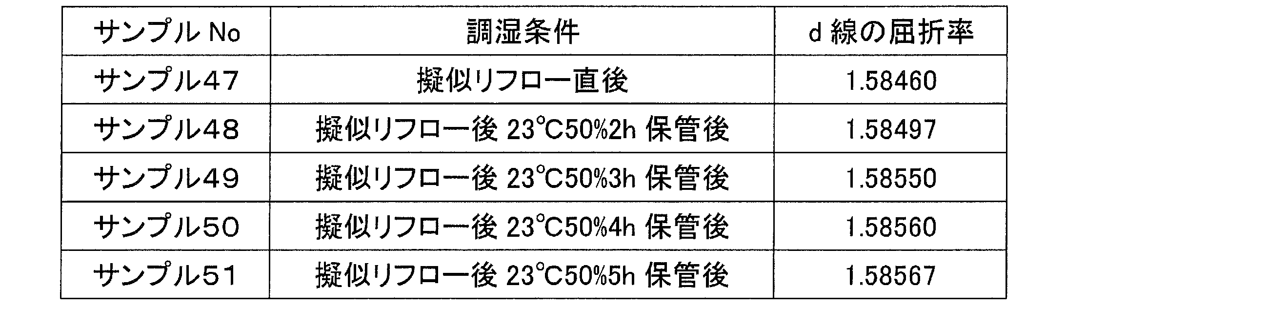
次に、調湿に適した時間の条件を調べるために、サンプル43と同組成の樹脂材料を用い、この樹脂材料に照射量6000mJの紫外線を照射し、その後、加熱装置(真空オーブン)30を用いて150℃、2時間の補助加熱を行って樹脂材料を硬化させ、サンプル47~51を成形した。その後、サンプル47~51を、上記ステップS3に相当する擬似リフロー即ち高温加熱処理として、加熱装置(真空オーブン)30を用いて、260℃で30分間の加熱を行った。直後にサンプル47の屈折率を測定した結果、d線の屈折率が1.58460となった。次に、温度23℃、相対湿度50%に設定の調湿装置40(恒温槽)を用いて、サンプル48を2時間保管して調湿し、サンプル49を3時間保管して調湿し、サンプル50を4時間保管して調湿し、サンプル51を5時間保管して調湿し、それぞれ屈折率を測定した結果、サンプル48のd線の屈折率が1.58497となり、サンプル49のd線の屈折率が1.58550となり、サンプル50のd線の屈折率が1.58560となり、サンプル51のd線の屈折率が1.58567となった。以上から、基準状態を実現する調湿条件として、調湿装置40に3時間以上置くことが望ましいといえる。以下の表3-3は、実験例3-3で得たサンプル47~51の処理内容と屈折率との関係を簡単にまとめたものである。
〔実験例3-4〕
次に、調湿に適した湿度の条件を調べるために、サンプル43と同組成の樹脂材料を用い、この樹脂材料に照射量6000mJの紫外線を照射し、その後、加熱装置(真空オーブン)30を用いて150℃、2時間の補助加熱を行って樹脂材料を硬化させ、サンプル52~58を成形した。その後、サンプル52~58を、上記ステップS3に相当する擬似リフロー即ち高温加熱処理として、加熱装置(真空オーブン)30を用いて、260℃で30分間の加熱を行った。その後、サンプル52を温度23℃、相対湿度20%に設定の調湿装置40に3時間保管して調湿し、屈折率を測定した結果、d線の屈折率が1.58505となった。同様に、サンプル53を温度23℃、相対湿度30%に設定の調湿装置40に3時間保管して調湿し、屈折率を測定した結果、d線の屈折率が1.58520となった。同様に、サンプル54を温度23℃、相対湿度40%に設定の調湿装置40に3時間保管して調湿し、屈折率を測定した結果、d線の屈折率が1.58535となった。同様に、サンプル55を温度23℃、相対湿度50%に設定の調湿装置40に3時間保管して調湿し、屈折率を測定した結果、d線の屈折率が1.58550となった。同様に、サンプル56を温度23℃、相対湿度60%に設定の調湿装置40に3時間保管して調湿し、屈折率を測定した結果、d線の屈折率が1.58564となった。同様に、サンプル57を温度23℃、相対湿度70%に設定の調湿装置40に3時間保管して調湿し、屈折率を測定した結果、d線の屈折率が1.58582となった。同様に、サンプル58を温度23℃、相対湿度80%に設定の調湿装置40に3時間保管して調湿し、屈折率を測定した結果、d線の屈折率が1.58595となった。このように、基準状態を実現する調湿条件として、恒温槽の湿度を50%±30%とする場合は、屈折率が、恒温槽湿度50%のときの屈折率に対して0.00050の範囲に収まっている。以下の表3-4は、実験例3-4で得たサンプル52~58の処理内容と屈折率との関係を簡単にまとめたものである。

次に、調湿に適した湿度の条件を調べるために、サンプル43と同組成の樹脂材料を用い、この樹脂材料に照射量6000mJの紫外線を照射し、その後、加熱装置(真空オーブン)30を用いて150℃、2時間の補助加熱を行って樹脂材料を硬化させ、サンプル52~58を成形した。その後、サンプル52~58を、上記ステップS3に相当する擬似リフロー即ち高温加熱処理として、加熱装置(真空オーブン)30を用いて、260℃で30分間の加熱を行った。その後、サンプル52を温度23℃、相対湿度20%に設定の調湿装置40に3時間保管して調湿し、屈折率を測定した結果、d線の屈折率が1.58505となった。同様に、サンプル53を温度23℃、相対湿度30%に設定の調湿装置40に3時間保管して調湿し、屈折率を測定した結果、d線の屈折率が1.58520となった。同様に、サンプル54を温度23℃、相対湿度40%に設定の調湿装置40に3時間保管して調湿し、屈折率を測定した結果、d線の屈折率が1.58535となった。同様に、サンプル55を温度23℃、相対湿度50%に設定の調湿装置40に3時間保管して調湿し、屈折率を測定した結果、d線の屈折率が1.58550となった。同様に、サンプル56を温度23℃、相対湿度60%に設定の調湿装置40に3時間保管して調湿し、屈折率を測定した結果、d線の屈折率が1.58564となった。同様に、サンプル57を温度23℃、相対湿度70%に設定の調湿装置40に3時間保管して調湿し、屈折率を測定した結果、d線の屈折率が1.58582となった。同様に、サンプル58を温度23℃、相対湿度80%に設定の調湿装置40に3時間保管して調湿し、屈折率を測定した結果、d線の屈折率が1.58595となった。このように、基準状態を実現する調湿条件として、恒温槽の湿度を50%±30%とする場合は、屈折率が、恒温槽湿度50%のときの屈折率に対して0.00050の範囲に収まっている。以下の表3-4は、実験例3-4で得たサンプル52~58の処理内容と屈折率との関係を簡単にまとめたものである。
〔実験例3-5〕
次に、リフロー前後での屈折率の変動を調べるために、サンプル43と同組成の樹脂材料を用い、この樹脂材料に照射量6000mJの紫外線を照射し、その後、加熱装置(真空オーブン)30を用いて150℃、2時間の補助加熱を行って樹脂材料を硬化させ、サンプル59を成形した。その後、サンプル59を、上記ステップS3に相当する擬似リフロー即ち高温加熱処理として、加熱装置(真空オーブン)30を用いて、260℃で30分間の加熱を行った。その後、サンプル59を、温度23℃、相対湿度50%に設定の調湿装置40(恒温槽)を用いて、3時間保管して調湿した。その後、サンプル59の屈折率を測定した結果、d線の屈折率が1.58550となった。その後、サンプル59をリフロー処理として260℃で10分間加熱し、次いで、サンプル59を、温度23℃、相対湿度50%に設定の調湿装置40(恒温槽)を用いて、3時間保管して調湿した。その後、サンプル59の屈折率を測定した結果、d線の屈折率が1.58531となった。以上から、リフロー前のサンプル59の屈折率と、リフロー後に湿気を吸収したサンプル59の屈折率差は0.00050以内の0.00019となり、屈折率差が十分小さいことがわかる。以下の表3-5は、実験例3-5で得たサンプル59の処理内容と屈折率の関係を簡単にまとめたものである。

次に、リフロー前後での屈折率の変動を調べるために、サンプル43と同組成の樹脂材料を用い、この樹脂材料に照射量6000mJの紫外線を照射し、その後、加熱装置(真空オーブン)30を用いて150℃、2時間の補助加熱を行って樹脂材料を硬化させ、サンプル59を成形した。その後、サンプル59を、上記ステップS3に相当する擬似リフロー即ち高温加熱処理として、加熱装置(真空オーブン)30を用いて、260℃で30分間の加熱を行った。その後、サンプル59を、温度23℃、相対湿度50%に設定の調湿装置40(恒温槽)を用いて、3時間保管して調湿した。その後、サンプル59の屈折率を測定した結果、d線の屈折率が1.58550となった。その後、サンプル59をリフロー処理として260℃で10分間加熱し、次いで、サンプル59を、温度23℃、相対湿度50%に設定の調湿装置40(恒温槽)を用いて、3時間保管して調湿した。その後、サンプル59の屈折率を測定した結果、d線の屈折率が1.58531となった。以上から、リフロー前のサンプル59の屈折率と、リフロー後に湿気を吸収したサンプル59の屈折率差は0.00050以内の0.00019となり、屈折率差が十分小さいことがわかる。以下の表3-5は、実験例3-5で得たサンプル59の処理内容と屈折率の関係を簡単にまとめたものである。
〔実験例3-6〕
次に、梱包に適した素材の透水について調べるために、サンプル43と同組成の樹脂材料を用い、この樹脂材料に照射量6000mJの紫外線を照射し、その後、加熱装置(真空オーブン)30を用いて150℃、2時間の補助加熱を行って樹脂材料を硬化させ、サンプル60~62を成形した。その後、サンプル60~62を、上記ステップS3に相当する擬似リフロー即ち高温加熱処理として、加熱装置(真空オーブン)30を用いて、260℃で30分間の加熱を行った。その後、サンプル60~62を、温度23℃、相対湿度50%に設定の調湿装置40(恒温槽)を用いて、3時間保管して調湿した。その後、サンプル60を透水度10g/m2・24hの素材で梱包し、温度23℃、相対湿度90%に設定の調湿装置40に48時間保管して調湿し、屈折率を測定した結果、d線の屈折率が1.58556となった。同様に、調湿処理後のサンプル61を透水度15g/m2・24hの素材で梱包し、温度23℃、相対湿度90%に設定の調湿装置40に48時間保管して調湿し、屈折率を測定した結果、d線の屈折率が1.58573となった。同様に、調湿処理後のサンプル62を透水度20g/m2・24hの素材で梱包し、温度23℃、相対湿度90%に設定の調湿装置40に48時間保管して調湿し、屈折率を測定した結果、d線の屈折率が1.58590となった。このように、梱包工程において、梱包材として透水度20g/m2・24h以下の素材を用いる場合は、屈折率の変化が0.00050以内に収まっている。以下の表3-6は、実験例3-6で得たサンプル60~62を梱包した素材の透水度と、サンプル60~62の屈折率の関係を簡単にまとめたものである。

次に、梱包に適した素材の透水について調べるために、サンプル43と同組成の樹脂材料を用い、この樹脂材料に照射量6000mJの紫外線を照射し、その後、加熱装置(真空オーブン)30を用いて150℃、2時間の補助加熱を行って樹脂材料を硬化させ、サンプル60~62を成形した。その後、サンプル60~62を、上記ステップS3に相当する擬似リフロー即ち高温加熱処理として、加熱装置(真空オーブン)30を用いて、260℃で30分間の加熱を行った。その後、サンプル60~62を、温度23℃、相対湿度50%に設定の調湿装置40(恒温槽)を用いて、3時間保管して調湿した。その後、サンプル60を透水度10g/m2・24hの素材で梱包し、温度23℃、相対湿度90%に設定の調湿装置40に48時間保管して調湿し、屈折率を測定した結果、d線の屈折率が1.58556となった。同様に、調湿処理後のサンプル61を透水度15g/m2・24hの素材で梱包し、温度23℃、相対湿度90%に設定の調湿装置40に48時間保管して調湿し、屈折率を測定した結果、d線の屈折率が1.58573となった。同様に、調湿処理後のサンプル62を透水度20g/m2・24hの素材で梱包し、温度23℃、相対湿度90%に設定の調湿装置40に48時間保管して調湿し、屈折率を測定した結果、d線の屈折率が1.58590となった。このように、梱包工程において、梱包材として透水度20g/m2・24h以下の素材を用いる場合は、屈折率の変化が0.00050以内に収まっている。以下の表3-6は、実験例3-6で得たサンプル60~62を梱包した素材の透水度と、サンプル60~62の屈折率の関係を簡単にまとめたものである。
〔実験例3-7〕
次に、樹脂の環境変動に対する耐性を調べるために、サンプル43と同組成の樹脂材料を用い、この樹脂材料に照射量6000mJの紫外線を照射し、その後、加熱装置(真空オーブン)30を用いて150℃、2時間の補助加熱を行って樹脂材料を硬化させ、サンプル63を成形した。その後、サンプル63を、上記ステップS3に相当する擬似リフロー即ち高温加熱処理として、加熱装置(真空オーブン)30を用いて、260℃で30分間の加熱を行った。直後にサンプル63の屈折率を測定した結果、d線の屈折率が1.58460となった。その後、サンプル63を、温度23℃、相対湿度50%に設定の調湿装置40(恒温槽)を用いて、3時間保管して調湿した。その後、サンプル63の屈折率を測定した結果、d線の屈折率が1.58550となった。その後、サンプル63を、温度60℃、相対湿度90%に設定の調湿装置40(恒温槽)を用いて、168時間保管した。その後、サンプル63の屈折率を測定した結果、d線の屈折率が1.58620となった。その後、サンプル63を、温度23℃、相対湿度50%に設定の調湿装置40(恒温槽)を用いて、3時間保管して調湿した。その後、サンプル63の屈折率を測定した結果、d線の屈折率が1.58551となった。その後、サンプル63を、温度85℃、相対湿度0%に設定の調湿装置40(恒温槽)を用いて、168時間保管して調湿した。その後、サンプル63の屈折率を測定した結果、d線の屈折率が1.58470となった。その後、サンプル63を、温度23℃、相対湿度50%に設定の調湿装置40(恒温槽)を用いて、3時間保管して調湿した。その後、サンプル63の屈折率を測定した結果、d線の屈折率が1.58548となった。このように、光学素子を高温高湿環境下に長時間曝すと屈折率が上昇するものの調湿工程を経ることで、屈折率が疑似リフロー処理後の調湿処理後の値にほぼ戻り、また、光学素子を高温低湿環境下に長時間曝すと屈折率が低下するものの調湿工程を経ることで、屈折率が疑似リフロー処理後の調湿処理後の値にほぼ戻ることが理解される。以下の表3-7は、実験例3-7で得たサンプル63の処理内容と屈折率との関係を簡単にまとめたものである。

次に、樹脂の環境変動に対する耐性を調べるために、サンプル43と同組成の樹脂材料を用い、この樹脂材料に照射量6000mJの紫外線を照射し、その後、加熱装置(真空オーブン)30を用いて150℃、2時間の補助加熱を行って樹脂材料を硬化させ、サンプル63を成形した。その後、サンプル63を、上記ステップS3に相当する擬似リフロー即ち高温加熱処理として、加熱装置(真空オーブン)30を用いて、260℃で30分間の加熱を行った。直後にサンプル63の屈折率を測定した結果、d線の屈折率が1.58460となった。その後、サンプル63を、温度23℃、相対湿度50%に設定の調湿装置40(恒温槽)を用いて、3時間保管して調湿した。その後、サンプル63の屈折率を測定した結果、d線の屈折率が1.58550となった。その後、サンプル63を、温度60℃、相対湿度90%に設定の調湿装置40(恒温槽)を用いて、168時間保管した。その後、サンプル63の屈折率を測定した結果、d線の屈折率が1.58620となった。その後、サンプル63を、温度23℃、相対湿度50%に設定の調湿装置40(恒温槽)を用いて、3時間保管して調湿した。その後、サンプル63の屈折率を測定した結果、d線の屈折率が1.58551となった。その後、サンプル63を、温度85℃、相対湿度0%に設定の調湿装置40(恒温槽)を用いて、168時間保管して調湿した。その後、サンプル63の屈折率を測定した結果、d線の屈折率が1.58470となった。その後、サンプル63を、温度23℃、相対湿度50%に設定の調湿装置40(恒温槽)を用いて、3時間保管して調湿した。その後、サンプル63の屈折率を測定した結果、d線の屈折率が1.58548となった。このように、光学素子を高温高湿環境下に長時間曝すと屈折率が上昇するものの調湿工程を経ることで、屈折率が疑似リフロー処理後の調湿処理後の値にほぼ戻り、また、光学素子を高温低湿環境下に長時間曝すと屈折率が低下するものの調湿工程を経ることで、屈折率が疑似リフロー処理後の調湿処理後の値にほぼ戻ることが理解される。以下の表3-7は、実験例3-7で得たサンプル63の処理内容と屈折率との関係を簡単にまとめたものである。
〔実験例4-1〕
実験例4-1では、レンズユニット10の樹脂層102を得るための樹脂材料として、ビニル系の紫外線硬化性樹脂材料を用いて各種の測定を行った。ここでは、紫外線硬化型ビニル系樹脂材料として、芳香族ビニル樹脂αイソプロピルスチレンに対し、UV硬化開始剤としてダウ・ケミカル製UVI-6992を0.5wt%添加したものを用いている。
実験例4-1では、レンズユニット10の樹脂層102を得るための樹脂材料として、ビニル系の紫外線硬化性樹脂材料を用いて各種の測定を行った。ここでは、紫外線硬化型ビニル系樹脂材料として、芳香族ビニル樹脂αイソプロピルスチレンに対し、UV硬化開始剤としてダウ・ケミカル製UVI-6992を0.5wt%添加したものを用いている。
まず、高温加熱工程の有無による屈折率の変化を調べるために、この樹脂材料に照射量1500mJの紫外線を照射し、その後、加熱装置(真空オーブン)30を用いて200℃、1時間の補助加熱を行って樹脂材料を硬化させ、サンプル64~65を成形した。その後、サンプル64を基準状態とするために、温度23℃、相対湿度50%に設定の調湿装置40(恒温槽)でサンプル64を3時間保管して調湿し、屈折率を測定した結果、d線の屈折率が1.49630となった。次にサンプル65を、上記ステップS3に相当する擬似リフロー即ち高温加熱処理として、加熱装置(真空オーブン)30を用いて、260℃で30分間の加熱を行った。その後、サンプル65を基準状態とするために、温度23℃、相対湿度50%に設定の調湿装置40(恒温槽)でサンプル65を3時間保管して調湿し、屈折率を測定した結果、d線の屈折率が1.49550となった。サンプル64~65の屈折率を比較すると、その差は0.00050以上の0.00080であり、高温加熱処理を行っていないサンプル64の方が屈折率が高い結果となった。この結果から、高温加熱処理前に通常行われる程度の補助加熱処理による効果のみではサンプル64を構成する樹脂の硬化具合が十分でなかったことがわかる。これに対して、高温加熱処理を行うことで、サンプル65の屈折率が低下し、硬化が進んだことがわかる。以下の表4-1は、実験例4-1で得たサンプル64~65の処理内容と屈折率との関係を簡単にまとめたものである。

〔実験例4-2〕
次に、吸水の影響を調べるために、サンプル64と同組成の樹脂材料を用い、この樹脂材料に照射量1500mJの紫外線を照射し、その後、加熱装置(真空オーブン)30を用いて200℃、1時間の補助加熱を行って樹脂材料を硬化させ、サンプル66~67を成形した。その後、サンプル66~67を、上記ステップS3に相当する擬似リフロー即ち高温加熱処理として、加熱装置(真空オーブン)30を用いて、260℃で30分間の加熱を行った。直後にサンプル66の屈折率を測定した結果、d線の屈折率が1.49470となった。次に、サンプル67を温度85℃、相対湿度85%に設定の調湿装置(恒温槽)40で2日間保管して樹脂を飽和吸水させた後、サンプル67の屈折率を測定した結果、d線の屈折率が1.49620となった。樹脂が十分に乾燥しているサンプル66と、樹脂が十分に吸水している状態のサンプル67の屈折率とを比較すると、その差は0.00100以上の0.00150であり、吸水による屈折率変化の大きい樹脂であることがわかる。以下の表4-2は、実験例4-2で得たサンプル66~67の処理内容と屈折率との関係を簡単にまとめたものである。

次に、吸水の影響を調べるために、サンプル64と同組成の樹脂材料を用い、この樹脂材料に照射量1500mJの紫外線を照射し、その後、加熱装置(真空オーブン)30を用いて200℃、1時間の補助加熱を行って樹脂材料を硬化させ、サンプル66~67を成形した。その後、サンプル66~67を、上記ステップS3に相当する擬似リフロー即ち高温加熱処理として、加熱装置(真空オーブン)30を用いて、260℃で30分間の加熱を行った。直後にサンプル66の屈折率を測定した結果、d線の屈折率が1.49470となった。次に、サンプル67を温度85℃、相対湿度85%に設定の調湿装置(恒温槽)40で2日間保管して樹脂を飽和吸水させた後、サンプル67の屈折率を測定した結果、d線の屈折率が1.49620となった。樹脂が十分に乾燥しているサンプル66と、樹脂が十分に吸水している状態のサンプル67の屈折率とを比較すると、その差は0.00100以上の0.00150であり、吸水による屈折率変化の大きい樹脂であることがわかる。以下の表4-2は、実験例4-2で得たサンプル66~67の処理内容と屈折率との関係を簡単にまとめたものである。
〔実験例4-3〕
次に、調湿に適した時間の条件を調べるために、サンプル64と同組成の樹脂材料を用い、この樹脂材料に照射量1500mJの紫外線を照射し、その後、加熱装置(真空オーブン)30を用いて200℃、1時間の補助加熱を行って樹脂材料を硬化させ、サンプル68~72を成形した。その後、サンプル68~72を、上記ステップS3に相当する擬似リフロー即ち高温加熱処理として、加熱装置(真空オーブン)30を用いて、260℃で30分間の加熱を行った。直後にサンプル68の屈折率を測定した結果、d線の屈折率が1.49470となった。次に、温度23℃、相対湿度50%に設定の調湿装置40(恒温槽)を用いて、サンプル69を2時間保管して調湿し、サンプル70を3時間保管して調湿し、サンプル71を4時間保管して調湿し、サンプル72を5時間保管して調湿し、それぞれ屈折率を測定した結果、サンプル69のd線の屈折率が1.49495となり、サンプル70のd線の屈折率が1.49550となり、サンプル71のd線の屈折率が1.49558となり、サンプル72のd線の屈折率が1.49565となった。以上から、基準状態を実現する調湿条件として、調湿装置40に3時間以上置くことが望ましいといえる。以下の表4-3は、実験例4-3で得たサンプル68~72の処理内容と屈折率との関係を簡単にまとめたものである。
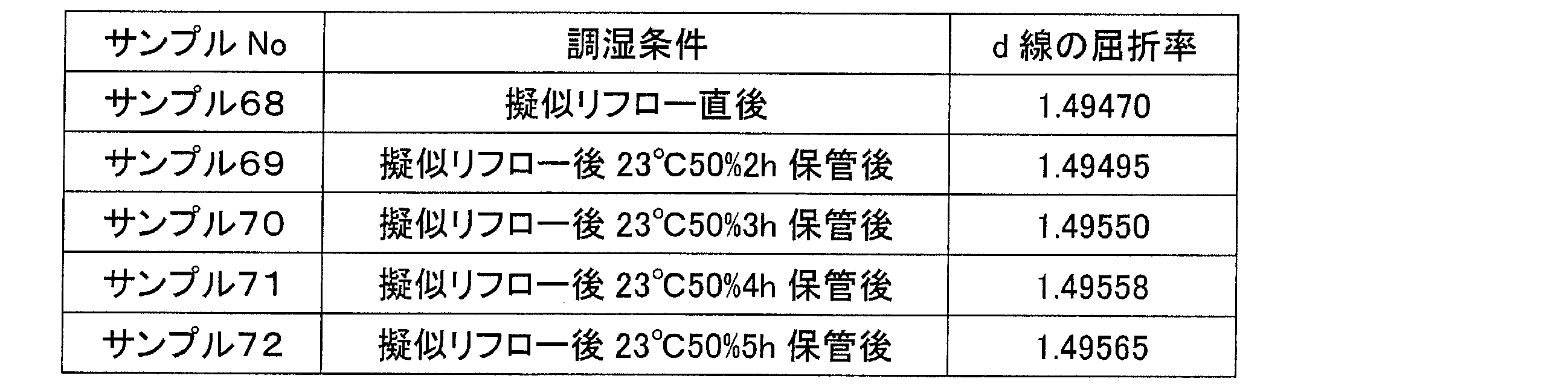
次に、調湿に適した時間の条件を調べるために、サンプル64と同組成の樹脂材料を用い、この樹脂材料に照射量1500mJの紫外線を照射し、その後、加熱装置(真空オーブン)30を用いて200℃、1時間の補助加熱を行って樹脂材料を硬化させ、サンプル68~72を成形した。その後、サンプル68~72を、上記ステップS3に相当する擬似リフロー即ち高温加熱処理として、加熱装置(真空オーブン)30を用いて、260℃で30分間の加熱を行った。直後にサンプル68の屈折率を測定した結果、d線の屈折率が1.49470となった。次に、温度23℃、相対湿度50%に設定の調湿装置40(恒温槽)を用いて、サンプル69を2時間保管して調湿し、サンプル70を3時間保管して調湿し、サンプル71を4時間保管して調湿し、サンプル72を5時間保管して調湿し、それぞれ屈折率を測定した結果、サンプル69のd線の屈折率が1.49495となり、サンプル70のd線の屈折率が1.49550となり、サンプル71のd線の屈折率が1.49558となり、サンプル72のd線の屈折率が1.49565となった。以上から、基準状態を実現する調湿条件として、調湿装置40に3時間以上置くことが望ましいといえる。以下の表4-3は、実験例4-3で得たサンプル68~72の処理内容と屈折率との関係を簡単にまとめたものである。
〔実験例4-4〕
次に、調湿に適した湿度の条件を調べるために、サンプル64と同組成の樹脂材料を用い、この樹脂材料に照射量1500mJの紫外線を照射し、その後、加熱装置(真空オーブン)30を用いて200℃、1時間の補助加熱を行って樹脂材料を硬化させ、サンプル73~79を成形した。その後、サンプル73~79を、上記ステップS3に相当する擬似リフロー即ち高温加熱処理として、加熱装置(真空オーブン)30を用いて、260℃で30分間の加熱を行った。その後、サンプル73を温度23℃、相対湿度20%に設定の調湿装置40に3時間保管して調湿し、屈折率を測定した結果、d線の屈折率が1.49507となった。同様に、サンプル74を温度23℃、相対湿度30%に設定の調湿装置40に3時間保管して調湿し、屈折率を測定した結果、d線の屈折率が1.49522となった。同様に、サンプル75を温度23℃、相対湿度40%に設定の調湿装置40に3時間保管して調湿し、屈折率を測定した結果、d線の屈折率が1.49536となった。同様に、サンプル76を温度23℃、相対湿度50%に設定の調湿装置40に3時間保管して調湿し、屈折率を測定した結果、d線の屈折率が1.49550となった。同様に、サンプル77を温度23℃、相対湿度60%に設定の調湿装置40に3時間保管して調湿し、屈折率を測定した結果、d線の屈折率が1.49563となった。同様に、サンプル78を温度23℃、相対湿度70%に設定の調湿装置40に3時間保管して調湿し、屈折率を測定した結果、d線の屈折率が1.49580となった。同様に、サンプル79を温度23℃、相対湿度80%に設定の調湿装置40に3時間保管して調湿し、屈折率を測定した結果、d線の屈折率が1.49593となった。このように、基準状態を実現する調湿条件として、恒温槽の湿度を50%±30%とする場合は、屈折率が、恒温槽湿度50%のときの屈折率に対して0.00050の範囲に収まっている。以下の表4-4は、実験例4-4で得たサンプル73~79の処理内容と屈折率との関係を簡単にまとめたものである。
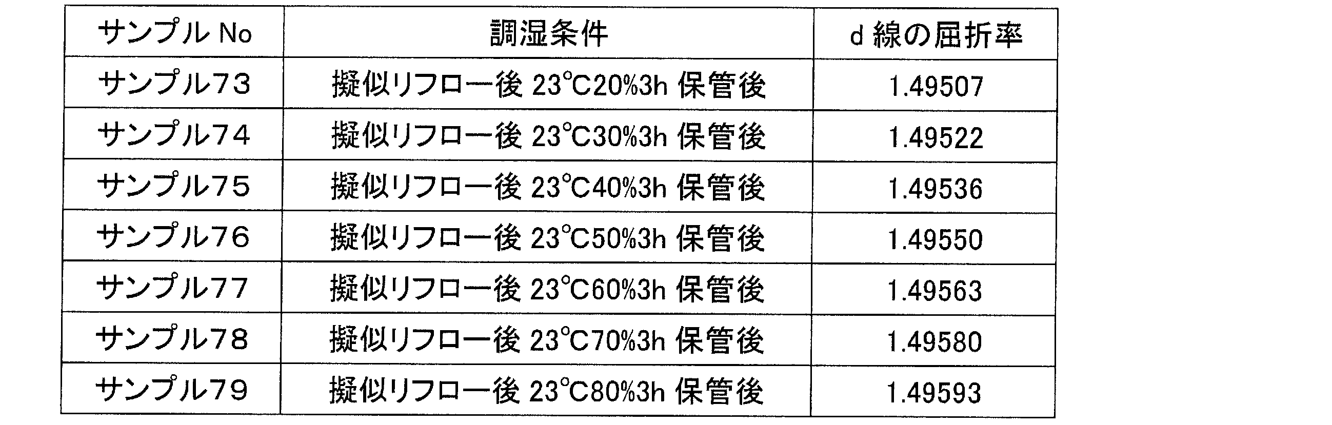
次に、調湿に適した湿度の条件を調べるために、サンプル64と同組成の樹脂材料を用い、この樹脂材料に照射量1500mJの紫外線を照射し、その後、加熱装置(真空オーブン)30を用いて200℃、1時間の補助加熱を行って樹脂材料を硬化させ、サンプル73~79を成形した。その後、サンプル73~79を、上記ステップS3に相当する擬似リフロー即ち高温加熱処理として、加熱装置(真空オーブン)30を用いて、260℃で30分間の加熱を行った。その後、サンプル73を温度23℃、相対湿度20%に設定の調湿装置40に3時間保管して調湿し、屈折率を測定した結果、d線の屈折率が1.49507となった。同様に、サンプル74を温度23℃、相対湿度30%に設定の調湿装置40に3時間保管して調湿し、屈折率を測定した結果、d線の屈折率が1.49522となった。同様に、サンプル75を温度23℃、相対湿度40%に設定の調湿装置40に3時間保管して調湿し、屈折率を測定した結果、d線の屈折率が1.49536となった。同様に、サンプル76を温度23℃、相対湿度50%に設定の調湿装置40に3時間保管して調湿し、屈折率を測定した結果、d線の屈折率が1.49550となった。同様に、サンプル77を温度23℃、相対湿度60%に設定の調湿装置40に3時間保管して調湿し、屈折率を測定した結果、d線の屈折率が1.49563となった。同様に、サンプル78を温度23℃、相対湿度70%に設定の調湿装置40に3時間保管して調湿し、屈折率を測定した結果、d線の屈折率が1.49580となった。同様に、サンプル79を温度23℃、相対湿度80%に設定の調湿装置40に3時間保管して調湿し、屈折率を測定した結果、d線の屈折率が1.49593となった。このように、基準状態を実現する調湿条件として、恒温槽の湿度を50%±30%とする場合は、屈折率が、恒温槽湿度50%のときの屈折率に対して0.00050の範囲に収まっている。以下の表4-4は、実験例4-4で得たサンプル73~79の処理内容と屈折率との関係を簡単にまとめたものである。
〔実験例4-5〕
次に、リフロー前後での屈折率の変動を調べるために、サンプル64と同組成の樹脂材料を用い、この樹脂材料に照射量1500mJの紫外線を照射し、その後、加熱装置(真空オーブン)30を用いて200℃、1時間の補助加熱を行って樹脂材料を硬化させ、サンプル80を成形した。その後、サンプル80を、上記ステップS3に相当する擬似リフロー即ち高温加熱処理として、加熱装置(真空オーブン)30を用いて、260℃で30分間の加熱を行った。その後、サンプル80を、温度23℃、相対湿度50%に設定の調湿装置40(恒温槽)を用いて、3時間保管して調湿した。その後、サンプル80の屈折率を測定した結果、d線の屈折率が1.49550となった。その後、サンプル80をリフロー処理として260℃で10分間加熱し、次いで、サンプル80を、温度23℃、相対湿度50%に設定の調湿装置40(恒温槽)を用いて、3時間保管して調湿した。その後、サンプル80の屈折率を測定した結果、d線の屈折率が1.49535となった。以上から、リフロー前のサンプル80の屈折率と、リフロー後に湿気を吸収したサンプル80の屈折率差は0.00050以内の0.00015となり、屈折率差が十分小さいことがわかる。以下の表4-5は、実験例4-5で得たサンプル80の処理内容と屈折率の関係を簡単にまとめたものである。

次に、リフロー前後での屈折率の変動を調べるために、サンプル64と同組成の樹脂材料を用い、この樹脂材料に照射量1500mJの紫外線を照射し、その後、加熱装置(真空オーブン)30を用いて200℃、1時間の補助加熱を行って樹脂材料を硬化させ、サンプル80を成形した。その後、サンプル80を、上記ステップS3に相当する擬似リフロー即ち高温加熱処理として、加熱装置(真空オーブン)30を用いて、260℃で30分間の加熱を行った。その後、サンプル80を、温度23℃、相対湿度50%に設定の調湿装置40(恒温槽)を用いて、3時間保管して調湿した。その後、サンプル80の屈折率を測定した結果、d線の屈折率が1.49550となった。その後、サンプル80をリフロー処理として260℃で10分間加熱し、次いで、サンプル80を、温度23℃、相対湿度50%に設定の調湿装置40(恒温槽)を用いて、3時間保管して調湿した。その後、サンプル80の屈折率を測定した結果、d線の屈折率が1.49535となった。以上から、リフロー前のサンプル80の屈折率と、リフロー後に湿気を吸収したサンプル80の屈折率差は0.00050以内の0.00015となり、屈折率差が十分小さいことがわかる。以下の表4-5は、実験例4-5で得たサンプル80の処理内容と屈折率の関係を簡単にまとめたものである。
〔実験例4-6〕
次に、梱包に適した素材の透水について調べるために、サンプル64と同組成の樹脂材料を用い、この樹脂に照射量1500mJの紫外線を照射し、その後、加熱装置(真空オーブン)30を用いて200℃、1時間の補助加熱を行って樹脂材料を硬化させ、サンプル81~83を成形した。その後、サンプル81~83を、上記ステップS3に相当する擬似リフロー即ち高温加熱処理として、加熱装置(真空オーブン)30を用いて、260℃で30分間の加熱を行った。その後、サンプル81~83を、温度23℃、相対湿度50%に設定の調湿装置40(恒温槽)を用いて、3時間保管して調湿した。その後、サンプル81を透水度10g/m2・24hの素材で梱包し、温度23℃、相対湿度90%に設定の調湿装置40に48時間保管して調湿し、屈折率を測定した結果、d線の屈折率が1.49555となった。同様に、調湿処理後のサンプル82を透水度15g/m2・24hの素材で梱包し、温度23℃、相対湿度90%に設定の調湿装置40に48時間保管して調湿し、屈折率を測定した結果、d線の屈折率が1.49571となった。同様に、調湿処理後のサンプル83を透水度20g/m2・24hの素材で梱包し、温度23℃、相対湿度90%に設定の調湿装置40に48時間保管して調湿し、屈折率を測定した結果、d線の屈折率が1.49587となった。このように、梱包工程において、梱包材として透水度20g/m2・24h以下の素材を用いる場合は、屈折率の変化が0.00050以内に収まっている。以下の表4-6は、実験例4-6で得たサンプル81~83を梱包した素材の透水度と、サンプル81~83の屈折率の関係を簡単にまとめたものである。

次に、梱包に適した素材の透水について調べるために、サンプル64と同組成の樹脂材料を用い、この樹脂に照射量1500mJの紫外線を照射し、その後、加熱装置(真空オーブン)30を用いて200℃、1時間の補助加熱を行って樹脂材料を硬化させ、サンプル81~83を成形した。その後、サンプル81~83を、上記ステップS3に相当する擬似リフロー即ち高温加熱処理として、加熱装置(真空オーブン)30を用いて、260℃で30分間の加熱を行った。その後、サンプル81~83を、温度23℃、相対湿度50%に設定の調湿装置40(恒温槽)を用いて、3時間保管して調湿した。その後、サンプル81を透水度10g/m2・24hの素材で梱包し、温度23℃、相対湿度90%に設定の調湿装置40に48時間保管して調湿し、屈折率を測定した結果、d線の屈折率が1.49555となった。同様に、調湿処理後のサンプル82を透水度15g/m2・24hの素材で梱包し、温度23℃、相対湿度90%に設定の調湿装置40に48時間保管して調湿し、屈折率を測定した結果、d線の屈折率が1.49571となった。同様に、調湿処理後のサンプル83を透水度20g/m2・24hの素材で梱包し、温度23℃、相対湿度90%に設定の調湿装置40に48時間保管して調湿し、屈折率を測定した結果、d線の屈折率が1.49587となった。このように、梱包工程において、梱包材として透水度20g/m2・24h以下の素材を用いる場合は、屈折率の変化が0.00050以内に収まっている。以下の表4-6は、実験例4-6で得たサンプル81~83を梱包した素材の透水度と、サンプル81~83の屈折率の関係を簡単にまとめたものである。
〔実験例4-7〕
次に、樹脂の環境変動に対する耐性を調べるために、サンプル64と同組成の樹脂材料を用い、この樹脂材料に照射量1500mJの紫外線を照射し、その後、加熱装置(真空オーブン)30を用いて200℃、1時間の補助加熱を行って樹脂材料を硬化させ、サンプル84を成形した。その後、サンプル84を、上記ステップS3に相当する擬似リフロー即ち高温加熱処理として、加熱装置(真空オーブン)30を用いて、260℃で30分間の加熱を行った。直後にサンプル84の屈折率を測定した結果、d線の屈折率が1.49470となった。その後、サンプル84を、温度23℃、相対湿度50%に設定の調湿装置40(恒温槽)を用いて、3時間保管して調湿した。その後、サンプル84の屈折率を測定した結果、d線の屈折率が1.49550となった。その後、サンプル84を、温度60℃、相対湿度90%に設定の調湿装置40(恒温槽)を用いて、168時間保管した。その後、サンプル84の屈折率を測定した結果、d線の屈折率が1.49618となった。その後、サンプル84を、温度23℃、相対湿度50%に設定の調湿装置40(恒温槽)を用いて、3時間保管して調湿した。その後、サンプル84の屈折率を測定した結果、d線の屈折率が1.49551となった。その後、サンプル84を、温度85℃、相対湿度0%に設定の調湿装置40(恒温槽)を用いて、168時間保管して調湿した。その後、サンプル84の屈折率を測定した結果、d線の屈折率が1.49474となった。その後、サンプル84を、温度23℃、相対湿度50%に設定の調湿装置40(恒温槽)を用いて、3時間保管して調湿した。その後、サンプル84の屈折率を測定した結果、d線の屈折率が1.49549となった。このように、光学素子を高温高湿環境下に長時間曝すと屈折率が上昇するものの調湿工程を経ることで、屈折率が疑似リフロー処理後の調湿処理後の値にほぼ戻り、また、光学素子を高温低湿環境下に長時間曝すと屈折率が低下するものの調湿工程を経ることで、屈折率が疑似リフロー処理後の調湿処理後の値にほぼ戻ることが理解される。以下の表4-7は、実験例4-7で得たサンプル84の処理内容と屈折率との関係を簡単にまとめたものである。
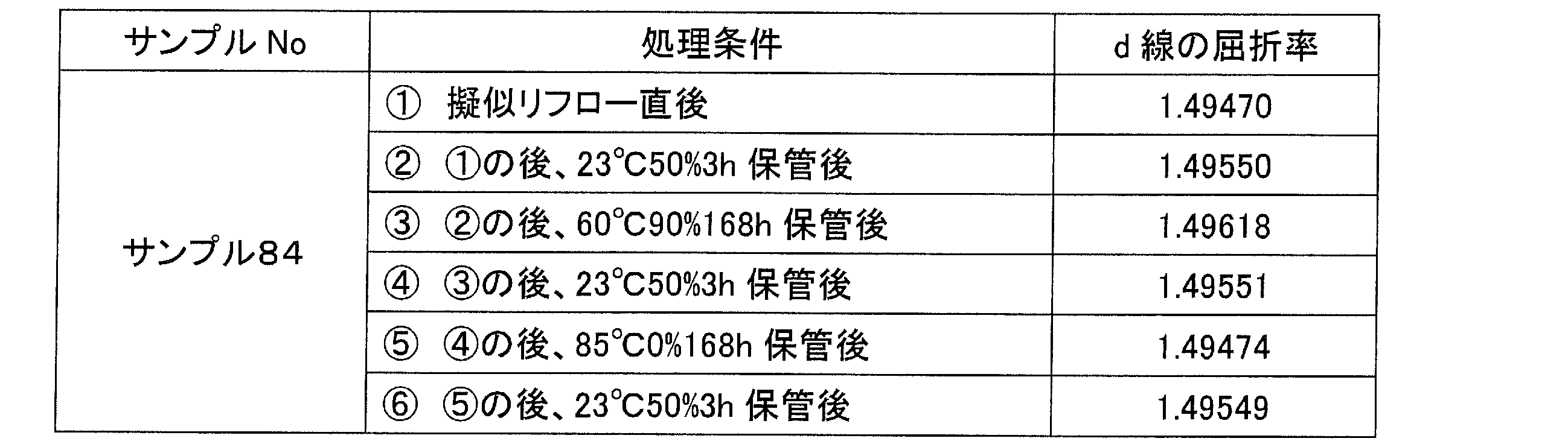
次に、樹脂の環境変動に対する耐性を調べるために、サンプル64と同組成の樹脂材料を用い、この樹脂材料に照射量1500mJの紫外線を照射し、その後、加熱装置(真空オーブン)30を用いて200℃、1時間の補助加熱を行って樹脂材料を硬化させ、サンプル84を成形した。その後、サンプル84を、上記ステップS3に相当する擬似リフロー即ち高温加熱処理として、加熱装置(真空オーブン)30を用いて、260℃で30分間の加熱を行った。直後にサンプル84の屈折率を測定した結果、d線の屈折率が1.49470となった。その後、サンプル84を、温度23℃、相対湿度50%に設定の調湿装置40(恒温槽)を用いて、3時間保管して調湿した。その後、サンプル84の屈折率を測定した結果、d線の屈折率が1.49550となった。その後、サンプル84を、温度60℃、相対湿度90%に設定の調湿装置40(恒温槽)を用いて、168時間保管した。その後、サンプル84の屈折率を測定した結果、d線の屈折率が1.49618となった。その後、サンプル84を、温度23℃、相対湿度50%に設定の調湿装置40(恒温槽)を用いて、3時間保管して調湿した。その後、サンプル84の屈折率を測定した結果、d線の屈折率が1.49551となった。その後、サンプル84を、温度85℃、相対湿度0%に設定の調湿装置40(恒温槽)を用いて、168時間保管して調湿した。その後、サンプル84の屈折率を測定した結果、d線の屈折率が1.49474となった。その後、サンプル84を、温度23℃、相対湿度50%に設定の調湿装置40(恒温槽)を用いて、3時間保管して調湿した。その後、サンプル84の屈折率を測定した結果、d線の屈折率が1.49549となった。このように、光学素子を高温高湿環境下に長時間曝すと屈折率が上昇するものの調湿工程を経ることで、屈折率が疑似リフロー処理後の調湿処理後の値にほぼ戻り、また、光学素子を高温低湿環境下に長時間曝すと屈折率が低下するものの調湿工程を経ることで、屈折率が疑似リフロー処理後の調湿処理後の値にほぼ戻ることが理解される。以下の表4-7は、実験例4-7で得たサンプル84の処理内容と屈折率との関係を簡単にまとめたものである。
〔第2実施形態〕
以下、図9を参照しながら、第2実施形態に係る光学素子を備える撮像ユニット及びその製造方法について説明する。
以下、図9を参照しながら、第2実施形態に係る光学素子を備える撮像ユニット及びその製造方法について説明する。
撮像装置である撮像ユニット500は、携帯電話などの移動情報端末機器の電子回路を構成する電子部品が実装される回路基板BBと、カメラモジュール400とを有している。カメラモジュール400は、回路基板BB上に実装されている。カメラモジュール400は、イメージセンサーとレンズとを組み合わせた小型のカメラ部分であり、撮像対象の画像取込ができるようになっている。即ち、カメラモジュール400は、本体モジュール5とレンズモジュール300とにより構成され、本体モジュール5を回路基板BBに実装することにより、カメラモジュール400全体が回路基板BBに実装される。本体モジュール5は、CCD(Charge Coupled Devices)やCMOS(Complementary Metal Oxide Semiconductor)等の撮像素子であるイメージセンサー11をサブ基板SB上に予め実装した受光モジュールであり、イメージセンサー11の上部は封止部12で封止されている。イメージセンサー11の上面には、光電変換を行う画素が多数格子状に配列された受光部11aが形成されており、この受光部11aにレンズモジュール300によって光学画像を結像させることにより、各画素での光電変換によって得た画像信号が出力される。サブ基板SBは、鉛フリーのはんだ18によって回路基板BBに実装される。これによりサブ基板SBを含むカメラモジュール400が回路基板BBに固定される。この際、サブ基板SBの接続用電極(図示略)と回路基板BB上面の回路電極(図示略)とが電気的に接続される。
レンズモジュール300は、結像レンズとしての撮像レンズ200を支持する筒状のレンズケース15を備えている。レンズケース15の上部には撮像レンズ200が保持されている。また、レンズケース15の下部はサブ基板SBに設けられた装着孔IS内に挿通されてレンズモジュール300をサブ基板SBに固定する装着部15bとなっている。この固定には、装着部15bを装着孔ISに圧入して固定する方法や、接着剤によって接着する方法などが用いられる。
撮像レンズ200は、既述のように第1及び第2レンズユニット10,110により構成され(図2参照)、被写体からの反射光をイメージセンサー11の受光部11a上に結像する。
以下、撮像ユニット500の製造方法について説明する。まず、撮像レンズ200を製造し、当該撮像レンズ200をレンズケース15の所定位置に組み込む。具体的には、レンズモジュール300のレンズケース15内に形成された上向きの支持部17aに撮像レンズ200のうち下方に位置する第2レンズユニット110のフランジ面122dを支持させる。その後、接着剤をレンズケース15の上方から供給して撮像レンズ200を周囲から固定する。以上により、撮像レンズ200は、イメージセンサー11の受光部11a上に結像させるようにレンズケース15内の適所位置に固定される。
次に、レンズモジュール300の上に形成された下向きの支持部17bを本体モジュール5におけるサブ基板SBの上面に支持させるように、レンズケース15の装着部15bをサブ基板SBの装着孔ISに挿通・固定し、カメラモジュール400を形成する。その後、予めはんだ18が塗布(ポッティング)された回路基板BBの所定の実装位置にカメラモジュール400やその他の電子部品を載置する。
そして、カメラモジュール400やその他の電子部品を載置した回路基板BBをベルトコンベア等でリフロー炉(図示略)に移送し、当該回路基板BBをリフロー処理に供して260℃程度の温度で加熱する。その結果、はんだ18が溶融してカメラモジュール400がその他の電子部品と一緒に回路基板BBに実装され撮像ユニット500が形成される。
なお、以上では、撮像レンズ200が第1及び第2レンズユニット10,110を含むものとして説明したが、単一のレンズユニット10のみで撮像レンズ200を構成することもできる。また、両レンズユニット10,110をレンズモジュール300のレンズケース15で直接支持する必要はなく、両レンズユニット10,110を保持するホルダー201(図2参照)をレンズケース15内の適所に支持することもできる。
以上説明した撮像ユニット500については、製造過程中の実装においてリフロー処理に供されるが、撮像ユニット500中に含まれる撮像レンズ200に対しては、上記リフロー処理を予定して予めこれに準ずる高温加熱工程及び調湿工程がなされている。従って、この撮像ユニット500は、リフロー処理を施しても、リフロー処理前後での撮像レンズ200の屈折率の変化を抑制できるので、所期の光学性能を有する状態に保つことができる。
以上、実施形態に即して本発明を説明したが、本発明は上記実施形態に限定されるものではなく、様々な変形が可能である。例えば、上記実施形態では、レンズユニット10等に対して成膜処理を行って光機能膜MBを形成しているが、このような成膜処理は必須のものではない。
また、図3のステップS2の硬化処理では、光硬化及び補助加熱処理を行っているが、樹脂層102,103を成形する光硬化性樹脂の種類の選択により、補助加熱処理を省略することもできる。さらに、樹脂層102,103を成形するため、光硬化性樹脂に代えて熱硬化性樹脂等を用いることもできる。
第1レンズユニット10等の外形、レンズ要素22,23の面形状等は、上記実施形態に例示されるものに限らず、用途に応じて様々な形状とすることができる。この際、第1レンズユニット10等から基板21を省略し、樹脂のみのレンズとすることもできる。
複数のウェハーレンズ100を個別にダイシングする必要はなく、複数のウェハーレンズ100を接着しつつ積層し、この積層体をダイシングして撮像レンズ200を得ることもできる。
高温加熱処理で行われる擬似的なリフロー処理の条件は、上記の具体例に限らず、エネルギー硬化性樹脂の種類、リフロー処理の条件等に応じて適宜変更される。
Claims (10)
- エネルギー硬化性樹脂材料を用いて光学素子を成形する成形工程と、
前記光学素子に対して予定されるリフロー処理に準ずる加熱処理を行う高温加熱工程と、
前記高温加熱工程を経た前記光学素子について、前記光学素子の性能評価を行う前に当該光学素子の調湿を行う調湿工程と、
を有する光学素子の製造方法。 - 前記光学素子は、前記高温加熱工程において実質的に飽和するまで硬化する、請求項1に記載の光学素子の製造方法。
- 前記調湿工程において、前記光学素子を、湿度50%±30%の環境下に3時間以上置くものとする、請求項1及び請求項2のいずれか一項に記載の光学素子の製造方法。
- 前記成形工程、前記高温加熱工程及び前記調湿工程を経て製造される前記光学素子の屈折率と、当該光学素子に対してさらに前記リフロー処理を施した後に、湿度50%±30%の環境下に3時間以上置いた当該光学素子の屈折率とについて、屈折率の差の絶対値が0.00050未満である、請求項1から請求項3までのいずれか一項に記載の光学素子の製造方法。
- 前記調湿工程後に前記光学素子の光学性能の性能評価を行う、請求項1から請求項4までのいずれか一項に記載の光学素子の製造方法。
- 前記調湿工程を経た前記光学素子を梱包材で梱包する梱包工程をさらに有する、請求項1から請求項5までのいずれか一項に記載の光学素子の製造方法。
- 前記梱包材は、透水度が20g/m2・24h以下の材料からなる、請求項6に記載の光学素子の製造方法。
- 前記エネルギー硬化性樹脂材料は、光硬化性樹脂材料である、請求項1から請求項7までのいずれか一項に記載の光学素子の製造方法。
- 請求項1から請求項8までのいずれか一項に記載の光学素子の製造方法により製造される光学素子。
- 請求項9に記載の光学素子と、
前記光学素子によって形成された像を検出する撮像素子と、
少なくとも前記光学素子を支持するホルダー部と、
を備える撮像ユニット。
Applications Claiming Priority (2)
| Application Number | Priority Date | Filing Date | Title |
|---|---|---|---|
| JP2011-017300 | 2011-01-28 | ||
| JP2011017300 | 2011-01-28 |
Publications (1)
| Publication Number | Publication Date |
|---|---|
| WO2012102396A1 true WO2012102396A1 (ja) | 2012-08-02 |
Family
ID=46580959
Family Applications (1)
| Application Number | Title | Priority Date | Filing Date |
|---|---|---|---|
| PCT/JP2012/051885 Ceased WO2012102396A1 (ja) | 2011-01-28 | 2012-01-27 | 光学素子の製造方法、光学素子及び撮像ユニット |
Country Status (1)
| Country | Link |
|---|---|
| WO (1) | WO2012102396A1 (ja) |
Cited By (1)
| Publication number | Priority date | Publication date | Assignee | Title |
|---|---|---|---|---|
| JP2016068453A (ja) * | 2014-09-30 | 2016-05-09 | 株式会社沖データ | 露光装置、画像形成装置、及び露光装置の製造方法 |
Citations (2)
| Publication number | Priority date | Publication date | Assignee | Title |
|---|---|---|---|---|
| JP2010019884A (ja) * | 2008-07-08 | 2010-01-28 | Konica Minolta Opto Inc | 撮像レンズの製造方法、撮像レンズ、撮像ユニット及び撮像ユニットの製造方法 |
| JP2011208092A (ja) * | 2010-03-30 | 2011-10-20 | Mitsubishi Chemicals Corp | 重合性組成物、硬化物、および光学部材 |
-
2012
- 2012-01-27 WO PCT/JP2012/051885 patent/WO2012102396A1/ja not_active Ceased
Patent Citations (2)
| Publication number | Priority date | Publication date | Assignee | Title |
|---|---|---|---|---|
| JP2010019884A (ja) * | 2008-07-08 | 2010-01-28 | Konica Minolta Opto Inc | 撮像レンズの製造方法、撮像レンズ、撮像ユニット及び撮像ユニットの製造方法 |
| JP2011208092A (ja) * | 2010-03-30 | 2011-10-20 | Mitsubishi Chemicals Corp | 重合性組成物、硬化物、および光学部材 |
Cited By (1)
| Publication number | Priority date | Publication date | Assignee | Title |
|---|---|---|---|---|
| JP2016068453A (ja) * | 2014-09-30 | 2016-05-09 | 株式会社沖データ | 露光装置、画像形成装置、及び露光装置の製造方法 |
Similar Documents
| Publication | Publication Date | Title |
|---|---|---|
| US8542309B2 (en) | Wafer-level lens array, method of manufacturing wafer-level lens array, lens module and imaging unit | |
| CN101691440B (zh) | 光学元件用树脂组合物、使用它的光学元件及光学透镜的制造方法 | |
| US8427748B2 (en) | Wafer-level lens array, method of manufacturing wafer-level lens array, lens module and imaging unit | |
| US20110063734A1 (en) | Master model of lens array and method of manufacturing the same | |
| JP5329299B2 (ja) | 光学レンズ | |
| WO2009157273A1 (ja) | 撮像光学系及び撮像用レンズの製造方法 | |
| JP2006076026A (ja) | 複合レンズ、複合レンズの製造方法、及びレンズモジュール | |
| WO2012102396A1 (ja) | 光学素子の製造方法、光学素子及び撮像ユニット | |
| JP5685054B2 (ja) | 半硬化物、硬化物およびそれらの製造方法、光学部品、硬化樹脂組成物 | |
| JP7753035B2 (ja) | 光学素子、光学素子の製造方法、樹脂組成物、光学機器及び撮像装置 | |
| WO2009122934A1 (ja) | 光学素子集合体及び光学ユニットの製造方法 | |
| JP2011237472A (ja) | 撮像用レンズ | |
| JP2011113075A (ja) | ウェハレベルレンズの製造方法 | |
| JPWO2011136139A1 (ja) | ウェハレンズ部材の製造方法、撮像レンズの製造方法、撮像モジュールの製造方法及び撮像モジュールを搭載した電子機器の製造方法 | |
| US20080233417A1 (en) | Optical polymer material and optical component | |
| JPWO2006077862A1 (ja) | エポキシ樹脂組成物及びそれを用いた光学材料 | |
| US20220239809A1 (en) | Polymerizable composition, optical element and method for producing the same, optical device, and image capturing apparatus | |
| US20200319475A1 (en) | Diffractive optical element, optical device, and imaging apparatus | |
| JP5568375B2 (ja) | 成形型及びレンズの製造装置、該製造装置により製造されたレンズ、該レンズを備える撮像装置 | |
| JP2023014556A (ja) | 回折光学素子、光学機器、撮像装置および回折光学素子の製造方法 | |
| JP2011207192A (ja) | マスタの製造方法 | |
| JP5514630B2 (ja) | レンズの製造装置及びレンズの製造方法、レンズ、撮像装置 | |
| JP2011113074A (ja) | ウェハレベルレンズの製造方法 | |
| US20250224543A1 (en) | Resin composition, optical element, optical apparatus, image pickup apparatus, and method for manufacturing optical element | |
| JP7451298B2 (ja) | 回折光学素子、光学機器および撮像装置 |
Legal Events
| Date | Code | Title | Description |
|---|---|---|---|
| 121 | Ep: the epo has been informed by wipo that ep was designated in this application |
Ref document number: 12738893 Country of ref document: EP Kind code of ref document: A1 |
|
| NENP | Non-entry into the national phase |
Ref country code: DE |
|
| 122 | Ep: pct application non-entry in european phase |
Ref document number: 12738893 Country of ref document: EP Kind code of ref document: A1 |
|
| NENP | Non-entry into the national phase |
Ref country code: JP |