WO2012102341A1 - 超電導ケーブルの接続構造及びその布設方法並びに超電導ケーブルの接続構造の真空引き方法 - Google Patents
超電導ケーブルの接続構造及びその布設方法並びに超電導ケーブルの接続構造の真空引き方法 Download PDFInfo
- Publication number
- WO2012102341A1 WO2012102341A1 PCT/JP2012/051660 JP2012051660W WO2012102341A1 WO 2012102341 A1 WO2012102341 A1 WO 2012102341A1 JP 2012051660 W JP2012051660 W JP 2012051660W WO 2012102341 A1 WO2012102341 A1 WO 2012102341A1
- Authority
- WO
- WIPO (PCT)
- Prior art keywords
- heat insulating
- pipe
- tube
- superconducting cable
- superconducting
- Prior art date
- Legal status (The legal status is an assumption and is not a legal conclusion. Google has not performed a legal analysis and makes no representation as to the accuracy of the status listed.)
- Ceased
Links
Images








Classifications
-
- H—ELECTRICITY
- H01—ELECTRIC ELEMENTS
- H01B—CABLES; CONDUCTORS; INSULATORS; SELECTION OF MATERIALS FOR THEIR CONDUCTIVE, INSULATING OR DIELECTRIC PROPERTIES
- H01B12/00—Superconductive or hyperconductive conductors, cables, or transmission lines
- H01B12/14—Superconductive or hyperconductive conductors, cables, or transmission lines characterised by the disposition of thermal insulation
-
- H—ELECTRICITY
- H01—ELECTRIC ELEMENTS
- H01R—ELECTRICALLY-CONDUCTIVE CONNECTIONS; STRUCTURAL ASSOCIATIONS OF A PLURALITY OF MUTUALLY-INSULATED ELECTRICAL CONNECTING ELEMENTS; COUPLING DEVICES; CURRENT COLLECTORS
- H01R4/00—Electrically-conductive connections between two or more conductive members in direct contact, i.e. touching one another; Means for effecting or maintaining such contact; Electrically-conductive connections having two or more spaced connecting locations for conductors and using contact members penetrating insulation
- H01R4/58—Electrically-conductive connections between two or more conductive members in direct contact, i.e. touching one another; Means for effecting or maintaining such contact; Electrically-conductive connections having two or more spaced connecting locations for conductors and using contact members penetrating insulation characterised by the form or material of the contacting members
- H01R4/68—Connections to or between superconductive connectors
-
- H—ELECTRICITY
- H02—GENERATION; CONVERSION OR DISTRIBUTION OF ELECTRIC POWER
- H02G—INSTALLATION OF ELECTRIC CABLES OR LINES, OR OF COMBINED OPTICAL AND ELECTRIC CABLES OR LINES
- H02G15/00—Cable fittings
- H02G15/08—Cable junctions
- H02G15/18—Cable junctions protected by sleeves, e.g. for communication cable
-
- H—ELECTRICITY
- H02—GENERATION; CONVERSION OR DISTRIBUTION OF ELECTRIC POWER
- H02G—INSTALLATION OF ELECTRIC CABLES OR LINES, OR OF COMBINED OPTICAL AND ELECTRIC CABLES OR LINES
- H02G15/00—Cable fittings
- H02G15/34—Cable fittings for cryogenic cables
-
- Y—GENERAL TAGGING OF NEW TECHNOLOGICAL DEVELOPMENTS; GENERAL TAGGING OF CROSS-SECTIONAL TECHNOLOGIES SPANNING OVER SEVERAL SECTIONS OF THE IPC; TECHNICAL SUBJECTS COVERED BY FORMER USPC CROSS-REFERENCE ART COLLECTIONS [XRACs] AND DIGESTS
- Y02—TECHNOLOGIES OR APPLICATIONS FOR MITIGATION OR ADAPTATION AGAINST CLIMATE CHANGE
- Y02E—REDUCTION OF GREENHOUSE GAS [GHG] EMISSIONS, RELATED TO ENERGY GENERATION, TRANSMISSION OR DISTRIBUTION
- Y02E40/00—Technologies for an efficient electrical power generation, transmission or distribution
- Y02E40/60—Superconducting electric elements or equipment; Power systems integrating superconducting elements or equipment
Definitions
- the present invention relates to a superconducting cable connection structure and its installation method for reducing heat intrusion and a superconducting cable connection structure vacuuming method.
- the superconducting cable is expected as a power cable capable of transmitting a large current with a low loss, and is being developed for practical use.
- a superconducting cable 10 shown in FIG. 2 is a single-core superconducting cable in which a single cable core 11 is housed in a heat insulating tube 12.
- the cable core 11 includes a former 111, a superconducting conductor layer 112, an electrical insulating layer 113, a superconducting shield layer 114, a normal conducting shield layer 115, a protective layer 116, and the like.
- the superconducting conductor layer 112 is formed by spirally winding a plurality of superconducting wires on the former 111.
- the superconducting shield layer 114 is formed by spirally winding a plurality of superconducting wires on the electrical insulating layer 113.
- the superconducting wire forming the superconducting conductor layer 112 and the superconducting shield layer 114 has, for example, a laminated structure in which an intermediate layer, a superconducting layer, and a protective layer are sequentially formed on a tape-like metal substrate.
- superconductors constituting the superconducting layer include RE-based superconductors (RE: rare earth elements) that exhibit superconductivity at a liquid nitrogen temperature (at atmospheric pressure of ⁇ 196 ° C.) or higher, and bismuth-based superconductors.
- an yttrium superconductor represented by the chemical formula YBa 2 Cu 3 O 7- ⁇ (hereinafter referred to as a Y-based superconductor) is typical. Further, it may be a tape-shaped superconducting wire in which a superconductor is formed in a metal matrix.
- a bismuth-based superconductor such as the chemical formula Bi 2 Sr 2 CaCu 2 O 8 + ⁇ (Bi2212), Bi 2 Sr 2 Ca 2 Cu 3 O 10 + ⁇ (Bi2223) can be applied.
- ⁇ represents an oxygen nonstoichiometric amount.
- the heat insulating tube 12 has a double tube structure including an inner tube 121 and an outer tube 122.
- a multilayer heat insulating layer (super insulation) 123 is interposed between the inner tube 121 and the outer tube 122 and is evacuated. Further, the outer periphery of the outer tube 122 is covered with an anticorrosion layer 124 such as polyvinyl chloride (PVC) or polyethylene.
- PVC polyvinyl chloride
- a refrigerant such as liquid nitrogen is circulated inside the inner pipe 121, and a transmission current flows through the superconducting conductor layer 112 in an extremely low temperature state.
- the superconducting cable 10 is shipped from a factory, and a plurality of superconducting cables 10 are connected by an intermediate connection portion to construct a line.
- the vacuum part is connected to the terminal part, the cable, and the intermediate connection part.
- the inside of the heat insulating tube 12 of the superconducting cable 10 is evacuated at the manufacturing stage, and a vacuum dividing portion 129 is formed at a certain length (for example, about 3 to 5 m) at the end of the heat insulating tube 12.
- Reference numeral 129a is a partition part by division).
- the vacuum break is not provided, the vacuum state is broken every time the intermediate connection portion and the termination connection portion are assembled. Therefore, the vacuum of the entire cable is performed after all the assembly is completed, so that the work time becomes long. .
- the length required for laying must be within a range that can be adjusted by cutting the section 129 described above, and the usable length is limited. There was a problem. Further, in the superconducting cable laying operation described in Patent Document 1, the heat insulating tube section 129 is communicated with the heat insulating region of the heat insulating container 130 and evacuated together with the heat insulating region.
- the object of the present invention is to reduce heat intrusion in a superconducting cable connection structure.
- the invention according to claim 1 is a connection structure in which a cable core having a former and a superconducting conductor layer is connected to each other by an intermediate connection portion between superconducting cables housed together with a refrigerant in the heat insulating pipe, and the heat insulating tube of the superconducting cable
- the intermediate connection portion has a double structure including an outer container and an inner container, and the heat insulating inner tube and the heat insulating member
- the outer pipe penetrates the wall surface of the outer container and is drawn to at least the wall surface of the inner container, and the drawing end part of the heat insulating inner pipe and the drawing end part of the heat insulating outer pipe are welded, for example,
- the region between the heat insulating inner tube and the heat insulating outer tube is sealed and the tube wall of the heat insulating outer tube is thinner than the outer heat insul
- the invention according to claim 2 has the same configuration as that of the invention according to claim 1, and the vacuum port of the intermediate connection portion is provided on the outer wall surface of the outer container through which the heat insulating outer tube passes, A vacuum port of the heat insulating tube is provided on an outer periphery of the outer tube outside the outer container.
- the invention described in claim 3 has the same configuration as that of the invention described in claim 1 or 2, and the corrugated tubular portion of the retracted portion of the heat insulating outer tube has a cross-sectional shape along the longitudinal direction of the heat insulating outer tube. However, it is characterized by having a waveform having a larger amplitude and a smaller wave pitch than the outer heat insulating outer tube.
- the invention according to claim 4 has the same configuration as the invention according to any one of claims 1 to 3, and the vacuum port of the heat insulating tube and the vacuum port of the intermediate connection part are both openable and closable. A switching valve that can be switched is provided.
- the invention described in claim 5 has the same configuration as that of the invention described in claim 4, and the vacuum port of the heat insulating tube and the vacuum port of the intermediate connection part can be connected to each other.
- the invention according to claim 6 is the laying method of the connection structure of the superconducting cable according to claim 1, wherein the superconducting cable is adjusted to a length for connecting to the intermediate connecting portion, After the space between the heat insulating outer tubes is sealed, evacuation is started from the vacuum port of the heat insulating tube, and another laying operation is performed in parallel with the evacuation.
- the invention according to claim 7 is the evacuation method for the superconducting cable connection structure according to claim 4, wherein the plurality of superconducting cables and the plurality of intermediate connection portions are alternately connected and connected to each other.
- the vacuum ports of the plurality of superconducting cables and the plurality of intermediate connection portions are simultaneously evacuated while connecting the vacuum ports of the superconducting cable and the intermediate connection portion and opening the switching valve.
- the heat insulating inner tube and the heat insulating outer tube are structured to be drawn into the intermediate connection portion after connecting the tip portions of each other and partitioning from the outside, so compared to the case where the heat insulating inner tube and the heat insulating outer tube are partitioned in advance.
- the amount of heat entering the inside of the heat insulating inner tube through the partition portion can be kept low, and high heat insulating properties can be obtained.
- the heat transfer path is long and thin, making it more effective for heat to enter the inside. It is possible to reduce it.
- the vacuum port of the intermediate connection portion is provided on the outer wall surface of the outer container on the side through which the heat insulating outer tube passes, and the vacuum port of the heat insulating tube is provided on the outer periphery of the heat insulating outer tube outside the outer container, It is possible to easily connect the superconducting cable and the vacuum region of the intermediate connection portion through each vacuum port, and it is possible to reduce the amount of heat penetration through the vacuum port.
- FIG. 5 is a diagram illustrating a work performed on the manufacturing site in the laying method of the connection structure of the superconducting cable and showing the work subsequent to FIG. 4.
- FIG. 6 is a diagram illustrating a work performed at the manufacturing site in the laying method of the connection structure of the superconducting cable and showing the next work of FIG. 5.
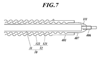
- FIG. 7 is a diagram illustrating a work performed on the manufacturing site in the laying method of the connection structure of the superconducting cable and showing the next work of FIG. 6.
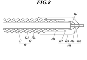
- FIG. 8 is a diagram illustrating a work performed at a manufacturing site in the laying method of the superconducting cable connection structure and showing a work subsequent to FIG. 7. It is a figure which shows the operation
- FIG. 10 is a diagram illustrating a work performed on the laying site in the laying method of the superconducting cable connection structure, and the next work of FIG. 9.
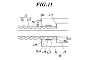
- FIG. 11 is a diagram showing a work performed at the site of laying in the laying method of the superconducting cable connection structure and showing the next work of FIG. 10. It is the figure which shows the other example of the operation
- FIG. 1 is a schematic diagram illustrating an example of laying a superconducting cable to which the superconducting cable connection structure according to the embodiment is applied
- FIG. 2 is a diagram illustrating an example of a laid superconducting cable.
- the superconducting cable 10 is laid out by connecting a plurality of superconducting cables 10 between the terminal connection portions 30, 30 arranged at the power supply source and the power supply destination, and the superconducting cable 10 and the superconducting cable. 10 are connected by an intermediate connecting portion 20.
- a pump P equipped with a refrigerator is also provided at the terminal connection portion 30, and a liquid refrigerant cooled along a heat insulating pipe 12 described later of each superconducting cable 10 is circulated to connect the cable core 11 (described later). Cooling is in progress.
- the present embodiment relates to a connection structure between the superconducting cable 10 and the intermediate connection portion 20.
- a superconducting cable 10 shown in FIG. 2 is a single-core superconducting cable in which a single cable core 11 is housed in a heat insulating tube 12.
- the cable core 11 includes a former 111, a superconducting conductor layer 112, an electrical insulating layer 113, a superconducting shield layer 114, a normal conducting shield layer 115, a protective layer 116, and the like.
- the former 111 is a winding core for forming the cable core 11, and is formed by twisting normal conductive wires such as copper wires, for example. In the former 111, an accident current flowing in the superconducting conductor layer 112 in the event of a short circuit accident is shunted.
- the superconducting conductor layer 112 is formed by spirally winding a plurality of superconducting wires on the former 111.
- the superconducting conductor layer 112 has a four-layer structure.
- a power transmission current flows through superconducting conductor layer 112 during steady operation.
- the superconducting wire constituting the superconducting conductor layer 112 has, for example, a laminated structure in which an intermediate layer, a superconducting layer, a protective layer, and the like are sequentially formed on a tape-shaped metal substrate.
- an RE-based superconductor (RE: rare earth element) exhibiting superconductivity at a liquid nitrogen temperature or higher, for example, a Y-based superconductor represented by the chemical formula YBa 2 Cu 3 O 7- ⁇ can be applied. . Further, it may be a tape-shaped superconducting wire in which a superconductor is formed in a metal matrix.
- a bismuth-based superconductor for example, the chemical formula Bi 2 Sr 2 CaCu 2 O 8 + ⁇ (Bi2212), Bi 2 Sr 2 Ca 2 Cu 3 O 10 + ⁇ (Bi2223) can be applied. In the chemical formula, ⁇ represents an oxygen nonstoichiometric amount.
- the electrical insulating layer 113 is made of, for example, insulating paper, semi-synthetic paper in which insulating paper and polypropylene film are joined, a polymer nonwoven fabric tape, and the like, and is formed by winding on the superconducting conductor layer 112.
- the superconducting shield layer 114 is formed by spirally winding a plurality of superconducting wires on the electrical insulating layer 113.
- the superconducting shield layer 114 has a two-layer structure. In the superconducting shield layer 114, substantially the same current as the conductor current flows in reverse phase by electromagnetic induction during steady operation.
- the superconducting wire constituting the superconducting shield layer 114 can be the same as the superconducting conductor layer 112.
- the normal conductive shield layer 115 is formed by winding a normal conductive wire such as a copper wire on the superconductive shield layer 114.
- the normal conducting shield layer 115 is shunted with an accident current flowing in the superconducting shield layer 114 in the event of a short circuit accident.
- the protective layer 116 is made of, for example, insulating paper, polymer nonwoven fabric, or the like, and is formed by winding on the normal conductive shield layer 115.
- the heat insulating tube 12 is a double member that includes the heat insulating inner tube 121 that accommodates the cable core 11 and is filled with a refrigerant (for example, liquid nitrogen), and the heat insulating outer tube 122 that is disposed so as to cover the outer periphery of the heat insulating inner tube 121. It has a tube structure.
- the heat insulating inner tube 121 and the heat insulating outer tube 122 are, for example, stainless corrugated tubes (corrugated tubes).
- a multilayer heat insulation layer (super insulation) 123 composed of a laminated body of polyethylene film vapor-deposited aluminum is interposed and kept in a vacuum state.
- pipe 122 is coat
- PVC polyvinyl chloride
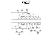
- FIG. 3 is a schematic diagram showing a connection structure between the superconducting cable 10 and the intermediate connection portion 20.
- the intermediate connecting portion 20 has a double structure including a connecting portion heat insulating inner tube 21 as an inner inner container and a connecting portion heat insulating outer tube 22 as an outer outer container, and the connecting portion heat insulating inner tube 21.
- the heat insulating outer tube 22 for connection part is formed from stainless steel.
- the heat insulating outer tube 22 for connection part is cylindrical, and end wall surfaces 221 are formed at both ends in the center line direction (only one is shown in FIG. 3).
- the connecting portion heat insulating outer tube 22 is provided with a switching valve capable of switching between opening and closing on both end wall surfaces 221 (the outer wall surface of the connecting portion heat insulating outer tube 22 on the side through which the heat insulating outer tube 122 passes).
- a vacuum port 222 for evacuation is provided. The vacuum port 222 is used for evacuating the heat insulating outer tube 22 for connecting portion when assembling the connection structure when the superconducting cable 10 is laid.
- the intermediate connection portion 20 is evacuated from the vacuum port 222 to a region between the heat insulation outer tube 22 for connection portion and the heat insulation inner tube 21 for connection portion when the intermediate connection portion 20 is laid.
- the intermediate connection portion 20 has two ends of the two superconducting cables 10 connected to both ends thereof (see FIG. 1), and the inner region of the heat insulating inner pipe 121 of each superconducting cable 10 and the connection portion are used.
- the inner region of the heat insulating inner pipe 21 communicates with the end wall surface 211, and the inner region is filled with the refrigerant. Further, the ends of the cable cores 11 of the respective superconducting cables 10 are connected to each other inside the heat insulating inner pipe 21 for the connection part.
- Both the heat insulating inner tube 121 and the heat insulating outer tube 122 of the superconducting cable 10 are drawn to the end wall surface 211 of the connecting portion heat insulating inner tube 21 of the intermediate connecting portion 20.
- the region between the heat insulating inner tube 121 and the heat insulating outer tube 122 is sealed so as to be sealed.
- tube 121 is uniformly formed of the corrugated pipe
- the heat insulating outer pipe 122 is formed mainly of a corrugated pipe on the outer side of the intermediate connecting portion 20, and is a straight pipe 125 (hereinafter referred to as a connecting straight pipe 125) that has no wave from the front side of the intermediate connecting portion 20 to the drawing portion. It is formed with.
- a bellows pipe 126 as a corrugated tubular part is formed at a portion inside the heat insulating outer pipe 22 for connecting part.
- the bellows pipe 126 has a larger radial amplitude (waveform amplitude) and a smaller wave pitch (waveform period) than the corrugated pipe outside the intermediate connection portion 20 in the heat insulating outer pipe 122. Yes. Further, the bellows pipe 126 is formed with a thinner wall than the corrugated pipe outside the intermediate connection portion 20 in the heat insulating outer pipe 122.
- a vacuum port 127 for performing evacuation provided with a switching valve that can be switched between opening and closing is provided at a portion of the connecting straight pipe 125 that is outside the connecting portion heat insulating outer pipe 22.
- the vacuum port 127 is used to evacuate the heat insulating tube 12 of the superconducting cable 10 when assembling the connection structure when the superconducting cable 10 is laid.
- the vacuum port 127 and the vacuum port 222 provided on the heat insulating outer tube 22 for the connecting portion of the intermediate connecting portion 20 are connected to enable direct passage.
- the intermediate connection portion 20 includes the vacuum ports 222 on the end wall surfaces 221 on both sides of the heat insulating outer tube 22 for the connection portion.
- each of the vacuum ports 127 and 222 is provided with a switching valve that can be opened and closed, the vacuum ports 127 and 222 are disconnected while the valves are closed, and the heat insulating tubes 12 of the individual superconducting cables 10 are separated.
- the insulation outer tube 22 for the connection part of each intermediate connection part 20 is inspected for the degree of vacuum, evacuated when the vacuum is reduced, or the superconducting cable 10 or the intermediate connection part 20 in which an abnormality has occurred is disconnected independently. It is possible to
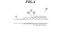
- FIG. 4 the ends of the heat insulating tube 12 are cut at both ends of the superconducting cable 10.
- FIG. 5 in order to seal the region between the heat insulating inner tube 121 and the heat insulating outer tube 122 of the cut heat insulating tube 12, a straight tube 401 a is provided at the tip of the heat insulating inner tube 121.
- the straight pipe 401b is welded to the distal end of the heat insulating outer pipe 122, and the straight pipe 401a and the straight pipe 401b are welded together to be sealed off, and the straight pipe 401 having a double structure closed at the distal end is connected.
- the straight pipe 401a inside the straight pipe 401 is equal in thickness to the heat insulating inner pipe 121 and the pipe wall, and the straight pipe 401b outside the straight pipe 401 is equal in thickness to the heat insulating outer pipe 122. used.
- a vacuum port 402 is provided in the straight tube 401 b outside the straight tube 401, and the inside of the heat insulating tube 12 is evacuated from the vacuum port 402.
- the inner region of the heat insulating inner tube 121 of the heat insulating tube 12 is closed with a substantially truncated cone-shaped lid 403.
- the lid body 403 is also joined to the straight pipe 401 by welding.
- the lid body 403 has a shape that is reduced in diameter toward the distal end portion, and the distal end portion is equipped with a vacuum port 404.
- a pooling eye structure 405 is formed at the opposite end of the superconducting cable 10.
- This pooling eye structure 405 is specifically for forming the pooling eye structure of the patented invention disclosed in Japanese Patent No. 4330008 (Japanese Patent). That is, as shown in FIG. 7, a sleeve 406 is joined to the former 111 exposed from the cable core 11 of the superconducting cable 10 by welding, and a circular straight pipe 407 extending from the outer end portion of the sleeve 406 is connected to the straight pipe 401.
- the heat insulating inner pipe 121 is joined by welding through the inner pipe.
- the circular straight pipe 407 has a pipe wall thickness larger than that of the heat insulating inner pipe 121 and smaller than that of the sleeve 406.
- the inner region of the heat insulation inner pipe 121 of the heat insulation pipe 12 of the superconducting cable 10 is hermetically sealed, so that vacuuming is executed from the vacuum port 404 of the lid 403 shown in FIG. To do.
- the protective tube 408 is joined to the distal end portion of the pooling eye structure 405 by welding, and the protective tube 408 and the heat insulating outer tube 122 are joined by welding with the circular straight tube 407.
- the circular straight pipe 409 having a wall thickness larger than that of the heat insulating outer pipe 122 and smaller than that of the protective pipe 408 is used. Thereby, the pooling eye structure 405 is completed.
- the vacuum port 404 When the degree of vacuum of the heat insulating inner pipe 121 becomes sufficiently high by evacuation, the vacuum port 404 is filled with a dry gas having a low dew point temperature (for example, N 2 gas), and the inside is filled with a predetermined positive pressure higher than atmospheric pressure. Put it in a state. Thus, the state in which the moisture inside is removed by evacuation is maintained. Moreover, about the area
- a dry gas having a low dew point temperature for example, N 2 gas
- a dry gas having a low dew point temperature (for example, N 2 gas) may be filled from the vacuum port 402, and the inside may be in a predetermined positive pressure state higher than the atmospheric pressure.
- N 2 gas a dry gas having a low dew point temperature
- the superconducting cable 10 is drawn using the pooling eye structure 405 and the laying operation is performed. And the positive pressure pressure inside the heat insulation inner pipe
- the inner region between the heat insulating inner tube 121 and the heat insulating outer tube 122 of the heat insulating tube 12 is transported while being kept in a vacuum, the inner region is filled with a dry gas (for example, N2 gas) having a low dew point temperature. Then return to atmospheric pressure.
- a dry gas for example, N2 gas
- the pooling eye structure 405 is removed from the tip of the superconducting cable 10.
- the heat insulating outer tube 122 is cut away from the heat insulating inner tube 121 by an amount corresponding to the mounting allowance of the connecting straight tube 125.
- the heat insulating inner tube 121 and the heat insulating outer tube 122 may be aligned at the ends. In that case, when joining the connecting straight pipe 125 to the heat insulating outer pipe 122, the straight pipe is also connected to the heat insulating inner pipe 121.
- an existing connecting straight pipe 125 including a bellows pipe 126 and a vacuum port 127 is joined to the heat insulating pipe 12.
- the inner edge portion of the front end portion of the connecting straight pipe 125 (on the connecting end portion side of the superconducting cable 10) is welded to the front end portion of the heat insulating inner tube 121 without a gap, and the rear end portion of the connecting straight tube 125 is insulated. It welds to the front-end
- the end portion on the opposite side of the superconducting cable 10 see FIG.
- the heat insulating tube 12 including the straight tube 401 is removed from the tip portion of the superconducting cable 10.
- the heat insulating outer tube 122 is cut away from the heat insulating inner tube 121 by an amount corresponding to the mounting allowance of the connecting straight tube 125.
- the existing straight pipe for connection 125 is joined to the heat insulation pipe 12 by the bellows pipe 126 and the vacuum port 127.
- the heat insulating pipe 12 is in a state where the region between the heat insulating inner pipe 121 and the heat insulating outer pipe 122 is sealed. Vacuuming is performed by the vacuum port 127. Since the superconducting cable 10 has already been evacuated and returned to atmospheric pressure with a dry gas having a low dew point temperature, the internal moisture that causes a delay in evacuation has been removed. The second evacuation can be completed in a shorter time than usual.
- the connection work between the cable core 11 of the superconducting cable 10 and the cable core 11 of the other superconducting cable 10 connected to the intermediate connection portion 20 is performed. And when the said connection operation
- a position 125b between the bellows pipe 126 and the vacuum port 127 of the connecting straight pipe 125 is joined to the inner edge of the end wall surface 221 of the connecting heat insulating outer pipe 22 by welding.
- pipe 22 for connection parts will be in the state sealed.
- each portion may be heated to generate thermal distortion, but the bellows pipe 126 can absorb expansion and contraction. Therefore, it is possible to avoid the occurrence of thermal distortion.
- the switching valve of the vacuum port 127 is closed, and then the intermediate connection portion 20 Vacuuming is performed from the vacuum port 222. Then, when the degree of vacuum of the intermediate connection part 20 becomes approximately the same as the degree of vacuum of the heat insulation pipe 12, the switching valve of the vacuum port 222 is once closed, and the vacuum port 127 of the heat insulation pipe 12 and the vacuum port 222 of the intermediate connection part 20 are closed. Are connected (see FIG. 3).
- both switching valves of the vacuum ports 127 and 222 are opened, and the region between the heat insulating outer tube 122 and the heat insulating inner tube 121 of the heat insulating tube 12 and the heat insulating outer tube 22 and the connecting portion for the connecting portion of the intermediate connecting portion 20 are connected.
- the region between the heat insulating inner pipes 21 is communicated.
- the cutting position of the heat insulating tube 12 is not limited, and the superconducting cable 10 can be adjusted to an arbitrary length.
- tube 122 are the structures of sealing each heat
- the bellows pipe 126 having a thinner tube wall than the outer heat insulating outer pipe 122 is provided at the drawing-in portion of the heat insulating outer pipe 122, the heat transfer path is long and thin, thereby effectively preventing the heat from entering the inside. It is possible to reduce it.
- the bellows pipe 126 has a cross-sectional shape along the center line direction of the pipe having a larger amplitude and a smaller wave pitch than the corrugated pipe of the heat insulating outer pipe 122 outside the intermediate connection portion 20. In addition, the heat penetration into the interior is further effectively reduced.
- the bellows pipe 126 not only absorbs the thermal expansion of the surroundings during heating due to welding work during laying, but also absorbs thermal expansion and contraction during temperature changes during the injection or discharge of the refrigerant. It is possible to effectively reduce the stress generated in the connection portion 20.
- the material of the connecting straight pipe 125 in FIG. 13 is SUS, and from the end wall surface 211 to the end wall surface 221 of the intermediate connection portion 20.
- the outer diameter of the straight pipe for connection is 150 mm and the thickness is 1 mm
- the intrusion heat without the bellows pipe 126 is 5 W
- the thickness of the bellows pipe 126 is 0.1 mm
- the length was set at 100 mm (effective length 1 m, amplitude 50 mm, period 10 mm, 10 cycle)
- the intrusion heat could be reduced to 0.1 W.
- the bellows tube 126 has an excellent prevention effect against heat intrusion.
- the vacuum port 127 of the heat insulating tube 12 is provided on the outer periphery of the portion that is outside the heat insulating outer tube 22 for the connecting portion of the connecting straight tube 125, and the heat insulating outer tube 122 passes through the vacuum port 222 of the intermediate connecting portion 20. Since the heat insulating outer tube 22 is provided on the end wall surface 221, the vacuum region of the superconducting cable 10 and the intermediate connection portion 20 can be easily connected through the vacuum ports 127 and 222, and the vacuum port 127. , 222 can reduce the amount of heat penetration.
- the vacuum port 127 of the heat insulating tube 12 and the vacuum port 222 of the intermediate connection unit 20 are each provided with a switching valve that can be switched between open and closed, when the vacuum port 127 and the vacuum port 222 are connected, Thus, it is possible to perform evacuation from one end of all the superconducting cables 10 to all the heat insulating regions in the system at once. Furthermore, the failure recovery location can be easily found by selecting and opening / closing the vacuum ports 127 and 222 as appropriate. In this case, all the compartments may be closed and the degree of vacuum at each part may be monitored. Further, when the failure is restored, if the vacuum compartments other than the corresponding places are closed, the evacuation places associated with the restoration can be limited.
- the connecting pipe 125 and the bellows pipe 126 are not attached to the superconducting cable 10 at the manufacturing site (factory) stage, but are attached at the installation site.
- the length of the superconducting cable 10 to be connected is accurately known in advance, the length of the heat insulating pipe 12 is adjusted at the stage of production (factory), and the connecting straight pipe 125 and The bellows pipe 126 may be attached and the inside of the heat insulating pipe 12 may be evacuated. In that case, as shown in FIG.
- the connecting straight pipe 125 and the bellows pipe 126 are inside the circular straight pipe 409 with respect to the superconducting cable 10 to which the connecting straight pipe 125 and the bellows pipe 126 are attached.
- the opposite side of the superconducting cable 10 is connected to the heat insulating inner tube 121 of the cut heat insulating tube 12 by welding as shown in FIG. 12B, and the heat insulating outer tube 122 is connected to the bellows tube 126.
- the vacuum port 127 are connected to the existing connecting straight pipe 125 by welding. Further, when the superconducting cable 10 is laid, as shown in FIG.
- the pooling eye structure 405 is removed, and the heat insulating inner pipe 121 (at the tip side of the connecting portion between the connecting straight pipe 125 and the heat insulating inner pipe 121). It is desirable to carry out the forming operation of the intermediate connection portion 20 after removing the broken line portion).
- the bellows pipe 126 may be made of a material other than a metal material as long as it can clear problems such as durability against temperature changes.
- it may be formed of a nonmetal such as Teflon (registered trademark).
- Teflon registered trademark
- the bellows pipe 126 may be formed of a metal, and a portion of the connecting straight pipe 125 other than the bellows pipe 126 may be formed of a nonmetal such as FRP.
- connection structure of the single-core superconducting cable 10 has been described.
- the present invention provides an intermediate connection portion 20 for a three-core superconducting cable in which three-core cable cores are collectively housed in a heat insulating tube. It can also be applied to the connection structure for.
Landscapes
- Physics & Mathematics (AREA)
- Condensed Matter Physics & Semiconductors (AREA)
- General Physics & Mathematics (AREA)
- Superconductors And Manufacturing Methods Therefor (AREA)
Abstract
Description
ケーブルコア11は、フォーマ111、超電導導体層112、電気絶縁層113、超電導シールド層114、常電導シールド層115、保護層116等で構成される。超電導導体層112は、フォーマ111の上に複数条の超電導線材を螺旋状に巻回することにより形成される。同様に、超電導シールド層114は、電気絶縁層113の上に複数条の超電導線材を螺旋状に巻回することにより形成される。
超電導ケーブル10の定常運転時には、内管121の内部に液体窒素などの冷媒が循環され、極低温状態で超電導導体層112に送電電流が流れることとなる。
従来の超電導ケーブルでは、真空部の区切りが無く、真空部は終端部もケーブルも中間接続部も全てつながっている。あるいは、図14に示すように、超電導ケーブル10の断熱管12の内部を製造段階で真空化し、断熱管12の端部において、一定の長さ(例えば3~5m程度)について真空の区分け部分129を形成する(符号129aは区分けによる仕切り部)。そして、現地で接続部を組み立てる際には、区分け部分129のみを切断して真空を破壊し、断熱管12全体は真空状態を維持したまま、中間接続部としての二重構造の断熱容器130に連結し、当該断熱容器130を用いて他の超電導ケーブルとの連結を図ることにより布設作業を行う方法が提案されている(例えば、特許文献1参照)。
また、特許文献1に記載の超電導ケーブルの布設作業では、断熱管の区分け部分129は、断熱容器130の断熱領域に連通され、断熱領域と共に真空引きが行われる。その結果、真空が破壊された区分け部分129からの熱の侵入は回避することが可能である。しかしながら、断熱管12を構成する内管121と外管122には、その過酷な温度変化などにおける耐久性の問題から金属管が使用され、高い熱伝導のため、上記区分けによる仕切り部129aが断熱容器130の入り口の近くに位置していると、外管122のb部分から仕切り部129aを介して断熱管12の内部に熱が侵入してしまうという問題があった。さらに、区分けされたケーブルには真空口がないため、真空引きが出来ず、断熱層のアウトガスで徐々に真空は悪くなる。また、接続部の真空を上げるためには、各接続部に真空ポンプを常設する必要がある。
また、断熱内管と断熱外管は、互いの先端部をつないで外部と仕切った後に、中間接続部内へ引き込む構造であることから、断熱内管と断熱外管とを予め仕切る場合に比べて、仕切り部を伝って断熱内管の内部への熱の侵入量を低く抑えることができ、高い断熱性を得ることが可能である。
さらに、断熱外管の引き込み部位にその外側の断熱外管よりも管壁の薄い波付き管状部を備えるので、熱の伝達経路が長く且つ薄いことにより、内部への熱の侵入をさらに効果的に低減することが可能である。
さらに、中間接続部の真空口を断熱外管が貫通する側の外部容器の外側の壁面に設け、断熱管の真空口を外部容器の外側にある断熱外管の外周に設けた場合には、超電導ケーブルと中間接続部の真空領域を簡易にそれぞれの真空口を通じて接続することが可能となると共に、真空口を通じた熱侵入量を低減することが可能となる。
以下、本発明の実施の形態を図面に基づいて詳細に説明する。
図1は実施形態に係る超電導ケーブルの接続構造を適用した超電導ケーブルの布設例を示す概略図、図2は布設される超電導ケーブルの一例を示す図である。
図1に示すように、超電導ケーブル10の布設は、電力の供給元と供給先とに配設した終端接続部30、30の間を複数の超電導ケーブル10で接続し、超電導ケーブル10と超電導ケーブル10とは中間接続部20で連結される。また、終端接続部30には、冷凍機を備えたポンプPが併設されており、各超電導ケーブル10の後述する断熱管12に沿って冷却した液体冷媒を循環させてケーブルコア11(後述)の冷却を行っている。
本実施形態は、超電導ケーブル10と中間接続部20との接続構造に関するものである。
図2に示す超電導ケーブル10は、断熱管12内に一心のケーブルコア11が収納された単心型の超電導ケーブルである。ケーブルコア11は、フォーマ111、超電導導体層112、電気絶縁層113、超電導シールド層114、常電導シールド層115、保護層116等により構成される。
超電導導体層112を構成する超電導線材は、例えば、テープ状の金属基板上に中間層、超電導層、保護層等が順に形成された積層構造を有している。超電導層を構成する超電導体には、液体窒素温度以上で超電導を示すRE系超電導体(RE:希土類元素)、例えば化学式YBa2Cu3O7-δで表されるY系超電導体を適用できる。また、金属マトリクス中に超電導体が形成されているテープ状の超電導線材でもよい。超電導体には、ビスマス系超電導体、例えば化学式Bi2Sr2CaCu2O8+δ(Bi2212), Bi2Sr2Ca2Cu3O10+δ(Bi2223)を適用できる。なお、化学式中のδは酸素不定比量を示す。
保護層116は、例えば絶縁紙、高分子不織布などで構成され、常電導シールド層115の上に巻回することにより形成される。
断熱内管121及び断熱外管122は、例えばステンレス製のコルゲート管(波付き管)である。断熱内管121と断熱外管122の間には、例えばアルミを蒸着したポリエチレンフィルムの積層体で構成された多層断熱層(スーパーインシュレーション)123が介在され、真空状態に保持される。また、断熱外管122の外周はポリ塩化ビニル(PVC)やポリエチレンなどの防食層124で被覆されている。
図3は超電導ケーブル10と中間接続部20の接続構造を示す概略図である。
中間接続部20は、内側の内部容器としての接続部用断熱内管21と、外側の外部容器としての接続部用断熱外管22からなる二重構造を有し、接続部用断熱内管21と接続部用断熱外管22はステンレスから形成されている。
接続部用断熱外管22は、筒状であってその中心線方向の両端部に端部壁面221が形成されており(図3では一方のみ図示)、接続部用断熱内管21は、接続部用断熱外管22の内部中央に配設され、筒状であって、その中心線方向の両端部に端部壁面211が形成されている(図3では一方のみ図示)。
接続部用断熱外管22には、両方の端部壁面221(断熱外管122が貫通する側の接続部用断熱外管22の外側の壁面)に開閉の切り替えが可能な切り替えバルブを備えた真空引きを行うための真空口222が装備されている。この真空口222は、超電導ケーブル10の布設時の接続構造の組み立ての際には、接続部用断熱外管22の真空引きに利用される。
そして、中間接続部20は、その布設時に、接続部用断熱外管22と接続部用断熱内管21との間の領域に対して真空口222から真空引きが行われて断熱構造が施される。この中間接続部20は、その両端部に連結される二つの超電導ケーブル10の端部がそれぞれ引き込まれており(図1参照)、各超電導ケーブル10の断熱内管121の内部領域と接続部用断熱内管21の内部領域とが端部壁面211を介して連通し、これらの内部領域には冷媒が充填される。また、接続部用断熱内管21の内部において、各超電導ケーブル10のケーブルコア11の端部同士が接続される。
前述したように、中間接続部20には両端側からそれぞれ超電導ケーブル10が引き込まれて接続されるが、各々の超電導ケーブル10の接続構造は同一であるため、一方の超電導ケーブル10と中間接続部20との接続構造についてのみ説明を行う。
そして、断熱内管121は、中間接続部20の引き込み部位も含めて一様にコルゲート管により形成されている。一方、断熱外管122は、中間接続部20の外側は主にコルゲート管で形成され、中間接続部20の手前から引き込み部位にかけて波のない直管125(以下、接続用直管125とする)で形成されている。
また、布設後は、この真空口127と中間接続部20の接続部用断熱外管22に設けられた真空口222とを連結して直通可能とする。前述したように、中間接続部20は接続部用断熱外管22の両側の端部壁面221に真空口222を備えるので、中間接続部20の両側において、真空口同士を接続することにより、中間接続部20に両側に接続された二つの超電導ケーブル10の断熱管12の内部(断熱外管122と断熱内管121の間の領域)を、中間接続部20の接続部用断熱外管22に形成された真空口222と断熱外管122に形成された真空口127とを介して連通した状態とすることが可能となる。従って、連結されている全ての超電導ケーブル10と中間接続部20とについて、上記接続を行うことにより、全ての超電導ケーブル10の断熱管12が連通した状態となり、経年使用により真空度の低下を生じた場合のメンテナンス時には、一端部側から真空引きを行うことで全ての超電導ケーブル10について断熱管12の真空引きを行うことが可能である。
また、各真空口127,222には、いずれも開閉可能な切り替えバルブが設けられているので、バルブを閉じた状態で真空口127と222とを切り離して、個々の超電導ケーブル10の断熱管12や個々の中間接続部20の接続部用断熱外管22について、真空度の検査や、真空の低下時の真空引きを行ったり、異常が生じた超電導ケーブル10や中間接続部20を単独で切り離したりすることが可能である。
以下、上記構成からなる超電導ケーブル10の接続構造の布設方法について図面と共に順を追って説明する。
まず、超電導ケーブル10の製造の現場(例えば工場)で行う予め行う作業について、図4から図8に基づいて説明する。
図4に示すように、超電導ケーブル10の両端部において、断熱管12の端部を切断する。
次に、図5に示すように、切断された断熱管12の断熱内管121と断熱外管122との間の領域を封止するために、断熱内管121の先端に直管401aを、断熱外管122の先端に直管401bを溶接し、直管401aと直管401bの先端を溶接することで封じ切り、先端部が閉塞された二重構造の直管401を接続する。なお、この直管401の内側の直管401aは断熱内管121と管壁の厚さが等しく、直管401の外側の直管401bは断熱外管122と管壁の厚さが等しいものが使用される。そして、この直管401の外側の直管401bには真空口402が設けられており、当該真空口402から断熱管12の内部の真空引きを行う。
かかる円形直管407を接合した時点で、超電導ケーブル10の断熱管12の断熱内管121の内部領域は密閉状態となるので、図6に示した蓋体403の真空口404から真空引きを実行する。
また、断熱管12の断熱内管121と断熱外管122との間の領域については、真空度が十分に高くなったら、真空引きを完了し、そのまま真空状態を維持しても良いし、断熱内管121の内部領域と同様に、真空口402から露点温度の低い乾燥ガス(例えば、N2ガス)を充填し、内部を大気圧より高い所定の正圧状態にしても良い。これによって、真空引きにより内部の水分が除去された状態を維持する。
ここまでが、製造の現場で行われる前処理であり、これ以降、超電導ケーブル10は、布設現場に輸送される。
そして、超電導ケーブル10の断熱内管121の内部の正圧圧力を測定し、当初の正圧圧力との差により漏れ等の異常を検査する。また、断熱管12の断熱内管121と断熱外管122との間の領域に乾燥ガスを充填した場合には、断熱内管121の内部と同様の検査を実施する。また、断熱管12の断熱内管121と断熱外管122との間の領域を真空に保ったまま運搬した場合には、当該内部領域に露点温度の低い乾燥ガス(例えば、N2ガス)を充填して大気圧まで戻してやる。
なお、超電導ケーブル10の逆側の端部(図6参照)についても、直管401を含む断熱管12の一部を超電導ケーブル10の先端部から除去する。このとき、断熱内管121に対して断熱外管122は、接続用直管125の取り付け代となる分だけ切除する。次に、断熱管12にベローズ管126と真空口127とが既設の接続用直管125を接合する。
超電導ケーブル10の両端部において、接続用直管125が接合されると、断熱管12は、断熱内管121と断熱外管122との間の領域が密閉された状態となるので、その時点で真空口127により真空引きを実施する。なお、超電導ケーブル10は、既に真空引きを実施すると共に露点温度の低い乾燥ガスで大気圧に戻しているため、真空引きの遅滞原因となる内部の湿気が除去されており、このため、この二回目の真空引きは通常よりも短時間で完了させることが可能である。
そして、上記連結作業が終わると、図11に示すように、中間接続部20を形成する。即ち、接続用直管125の先端部の外縁部125a、断熱内管121の先端部の外縁部121aと接続部用断熱内管21の端部壁面211の内縁部とが溶接により接合される。
また、接続用直管125のベローズ管126と真空口127との間の位置125bが、接続部用断熱外管22の端部壁面221の内縁部と溶接により接合される。これにより、中間接続部20の接続部用断熱内管21と接続部用断熱外管22との間の領域が密閉された状態となる。
上記接続用直管125、接続部用断熱内管21及び接続部用断熱外管22の溶接時には、各部が加熱されて熱歪みを発生しうるが、ベローズ管126は伸縮を吸収することが可能であるため、熱歪みの発生を回避することが可能である。
そして、中間接続部20の真空度が断熱管12の真空度と同程度となったら、真空口222の切り替えバルブを一旦閉じて、断熱管12の真空口127と中間接続部20の真空口222とを連結する(図3参照)。その後、各真空口127,222の切り替えバルブをいずれも開放し、断熱管12の断熱外管122と断熱内管121の間の領域と中間接続部20の接続部用断熱外管22と接続部用断熱内管21の間の領域が連通される。
なお、上記液体窒素の充填時に、断熱管12は収縮するが、その際の収縮もベローズ管126が吸収し、歪みを低減することが可能である。
上記の超電導ケーブル10の接続構造によれば、超電導ケーブル10の布設時において、断熱管12の切断位置の制限がなく、超電導ケーブル10を任意の長さに調節することが可能である。
また、断熱内管121と断熱外管122は、中間接続部20内へ引き込まれた各々の引き込み端部同士を封止して断熱管12を密閉する構造であることから、断熱内管121と断熱外管122とを接合する仕切り部を途中に設ける従来の構造に比べて、仕切り部を伝って断熱内管121の内部への熱の侵入を防止することができ、断熱内管121の内側に対して、高い断熱性を得ることが可能である。
特に、ベローズ管126は、その管の中心線方向に沿った断面形状が、中間接続部20の外側の断熱外管122のコルゲート管よりも振幅が大きく、波のピッチが小さい波形であることから、内部への熱の侵入をさらに効果的に低減する。
また、ベローズ管126は、布設時の溶接作業による加熱時の周囲の熱膨張を吸収するだけでなく、冷媒の注入或いは排出時における温度変化の際の熱伸縮も吸収し、超電導ケーブル10及び中間接続部20の内部に生じる応力を効果的に低減することが可能である。
また、断熱管12の真空口127と中間接続部20の真空口222は、いずれも開閉の切り替えが可能な切り替えバルブを備えていることから、真空口127と真空口222を連結した場合には、全超電導ケーブル10の一端から系内全ての断熱領域内に対する真空引きを一度に行うことが可能となる。
さらに、各真空口127,222を適宜選択して開閉操作することにより、故障復旧場所の発見も容易である。この場合、全ての区画を閉にしておき、各部位の真空度をモニタリングすればよい。さらに、故障復旧時には、該当箇所以外の真空区画を閉にしておけば、復旧に伴う真空引き箇所を限定する事が出来る。
なお、前述した超電導ケーブル10の接続構造の布設作業の例では、製造の現場(工場)の段階では、超電導ケーブル10に接続用直管125及びベローズ管126は取り付けずに、布設現場において取り付けを行っていたが、接続を行う超電導ケーブル10の長さが予め正確に分かっている場合には、製造の現場(工場)の段階で断熱管12の長さを調節し、接続用直管125及びベローズ管126の取り付けを行い、断熱管12の内部の真空引きを行っても良い。その場合、図12Aに示すように、接続用直管125及びベローズ管126が取り付けられた状態の超電導ケーブル10に対して、接続用直管125及びベローズ管126が円形直管409の内側となるようにプーリングアイ構造405を施した上で、工場から布設現場に出荷することが望ましい。なお、図12Aに示す超電導ケーブル10の逆側は、図12Bのように、切断された断熱管12の断熱内管121に蓋体403が溶接により接続され、断熱外管122にはベローズ管126と真空口127とが既設の接続用直管125が溶接により接続されている。
また、上記超電導ケーブル10の布設時には、図13に示すように、プーリングアイ構造405を除去すると共に、接続用直管125と断熱内管121との接合部よりも先端側の断熱内管121(破線部分)を除去した後に中間接続部20の形成作業を実施することが望ましい。
以上、本発明者によってなされた発明を実施形態に基づいて具体的に説明したが、本発明は上記実施形態に限定されるものではなく、その要旨を逸脱しない範囲で変更可能である。
例えば、上記ベローズ管126は、温度変化に対する耐久性などの問題をクリアすることが可能であれば、金属材料以外を使用しても良い。例えば、テフロン(登録商標)の様な非金属で形成してもよい。その場合には、熱伝導が金属より小さいので、ベローズ管126の管中心線方向における長さをより短くすることも可能である。また、ベローズ管126は金属で形成し、接続用直管125のベローズ管126以外の部分をFRPなどの非金属で形成しても良い。
11 ケーブルコア
111 フォーマ
112 超電導導体層
113 電気絶縁層
114 超電導シールド層
115 常電導シールド層
116 保護層
12 断熱管
121 断熱内管
122 断熱外管
123 多層断熱層
124 防食層
125 接続用直管
126 ベローズ管(波付き管状部)
127 真空口
20 中間接続部
21 接続部用断熱内管(内部容器)
221 端部壁面(外側の壁面)
22 接続部用断熱外管(外部容器)
222 真空口
Claims (7)
- フォーマと超電導導体層を有するケーブルコアが、断熱管内で冷媒と共に収容されてなる超電導ケーブル同士を中間接続部により接続する接続構造であって、
前記超電導ケーブルの断熱管は、それぞれが波付き管である断熱内管と断熱外管とによる二重構造を採ると共に、前記中間接続部は、外部容器と内部容器による二重構造を採り、
前記断熱内管と前記断熱外管とは、前記外部容器の壁面を貫通し、少なくとも前記内部容器の壁面まで引き込まれており、前記断熱内管の引き込み端部と前記断熱外管の引き込み端部とを接合して前記断熱内管と前記断熱外管の間の領域と前記外部容器と内部容器の間の領域のそれぞれを密閉し、
前記断熱外管の前記外部容器の壁面より内側となる引き込み部位に、外部の前記断熱外管よりも管壁の薄い波付き管状部を設け、
前記断熱管と前記中間接続部とに、各々の内部の真空引きを行うための真空口を設けたことを特徴とする超電導ケーブルの接続構造。 - 前記中間接続部の真空口は、前記断熱外管が貫通する側の外部容器の外側の壁面に設けられ、
前記断熱管の真空口は、前記外部容器の外側にある前記断熱外管の外周に設けられていることを特徴とした請求項1の超電導ケーブルの接続構造。 - 前記断熱外管の引き込み部位の波付き管状部は、前記断熱外管の長手方向に沿った断面形状が、外側の前記断熱外管よりも振幅が大きく、波のピッチが小さい波形であることを特徴とする請求項1又は2記載の超電導ケーブルの接続構造。
- 前記断熱管の真空口と前記中間接続部の真空口は、いずれも開閉の切り替えが可能な切り替えバルブを備えることを特徴とする請求項1から3のいずれか一項に記載の超電導ケーブルの接続構造。
- 前記断熱管の真空口と前記中間接続部の真空口は、互いに接続可能であることを特徴とする請求項4記載の超電導ケーブルの接続構造。
- 請求項1記載の超電導ケーブルの接続構造の布設方法であって、
前記超電導ケーブルが前記中間接続部に接続するための長さに調整され、前記断熱内管と前記断熱外管の間が密閉された後に、当該断熱管の真空口から真空引きを開始し、当該真空引きと並行して、他の布設作業を行うことを特徴とする超電導ケーブルの接続構造の布設方法。 - 請求項4記載の超電導ケーブルの接続構造の真空引き方法であって、
複数の前記超電導ケーブルと複数の前記中間接続部とが交互に接続され、
互いに接続された前記超電導ケーブル及び前記中間接続部の前記真空口同士を連結すると共に前記切り替えバルブを開いた状態で前記複数の超電導ケーブルと前記複数の中間接続部とについて同時に真空引きを行うことを特徴とする超電導ケーブルの接続構造の真空引き方法。
Priority Applications (3)
| Application Number | Priority Date | Filing Date | Title |
|---|---|---|---|
| JP2012554837A JP5920836B2 (ja) | 2011-01-27 | 2012-01-26 | 超電導ケーブルの接続構造及びその布設方法並びに超電導ケーブルの接続構造の真空引き方法 |
| CN201280001971.7A CN102986103B (zh) | 2011-01-27 | 2012-01-26 | 超导电缆的连接结构及其布设方法以及超导电缆的连接结构的抽真空方法 |
| US13/816,621 US8946125B2 (en) | 2011-01-27 | 2012-01-26 | Connection structure for superconductive cables, method for laying the same, and method for vacuuming connection structure for superconductive cables |
Applications Claiming Priority (2)
| Application Number | Priority Date | Filing Date | Title |
|---|---|---|---|
| JP2011-014664 | 2011-01-27 | ||
| JP2011014664 | 2011-01-27 |
Publications (1)
| Publication Number | Publication Date |
|---|---|
| WO2012102341A1 true WO2012102341A1 (ja) | 2012-08-02 |
Family
ID=46580905
Family Applications (1)
| Application Number | Title | Priority Date | Filing Date |
|---|---|---|---|
| PCT/JP2012/051660 Ceased WO2012102341A1 (ja) | 2011-01-27 | 2012-01-26 | 超電導ケーブルの接続構造及びその布設方法並びに超電導ケーブルの接続構造の真空引き方法 |
Country Status (4)
| Country | Link |
|---|---|
| US (1) | US8946125B2 (ja) |
| JP (1) | JP5920836B2 (ja) |
| CN (1) | CN102986103B (ja) |
| WO (1) | WO2012102341A1 (ja) |
Cited By (3)
| Publication number | Priority date | Publication date | Assignee | Title |
|---|---|---|---|---|
| KR20170058841A (ko) * | 2015-11-19 | 2017-05-29 | 엘에스전선 주식회사 | 초전도 케이블의 중간 접속을 위한 중간 접속구조 |
| CN114420370A (zh) * | 2021-12-30 | 2022-04-29 | 深圳供电局有限公司 | 一种超导隔离开关及相应的绝热端子箱 |
| JP2022174398A (ja) * | 2021-05-11 | 2022-11-24 | 株式会社ササクラ | 真空二重配管と流体機器との接続構造 |
Families Citing this family (10)
| Publication number | Priority date | Publication date | Assignee | Title |
|---|---|---|---|---|
| KR102272723B1 (ko) * | 2013-10-31 | 2021-07-06 | 엘에스전선 주식회사 | 초전도 전력 시스템 및 초전도 케이블 포설방법 |
| JP6140377B2 (ja) * | 2015-02-10 | 2017-05-31 | 古河電気工業株式会社 | 超電導ケーブル及び超電導ケーブルの製造方法 |
| CN105845271B (zh) * | 2016-05-19 | 2018-06-19 | 胡光南 | 一种高温超导充电电缆 |
| CN108194767A (zh) * | 2017-12-18 | 2018-06-22 | 上海电缆研究所有限公司 | 超导电缆绝热管的吸附件在线激活结构和在线激活方法 |
| CN109494011A (zh) * | 2018-12-27 | 2019-03-19 | 上海胜华电气股份有限公司 | 一种低成本超导电缆 |
| KR102619343B1 (ko) * | 2019-01-04 | 2023-12-28 | 엘에스전선 주식회사 | 진공부 구획장치 및 이를 구비하는 초전도 케이블 |
| KR102608511B1 (ko) * | 2019-01-04 | 2023-11-30 | 엘에스전선 주식회사 | 진공부 구획장치 및 이를 구비하는 초전도 케이블 |
| CN114843984B (zh) * | 2022-05-06 | 2023-07-25 | 中国科学院合肥物质科学研究院 | 一种在低温真空环境中使用的高电压密封多芯束线器 |
| CN115459202B (zh) * | 2022-08-12 | 2025-07-11 | 富通集团(天津)超导技术应用有限公司 | 一种超导电缆免焊接密封端头及安装方法 |
| FR3159056B1 (fr) * | 2024-02-06 | 2026-06-12 | Nexans | Ensemble de connexion de deux câbles supraconducteurs |
Citations (6)
| Publication number | Priority date | Publication date | Assignee | Title |
|---|---|---|---|---|
| JPS5074185A (ja) * | 1973-11-05 | 1975-06-18 | ||
| JPS63257136A (ja) * | 1987-04-14 | 1988-10-25 | 日立電線株式会社 | 真空引き液体充填装置 |
| JP2000340274A (ja) * | 1999-05-28 | 2000-12-08 | Sumitomo Electric Ind Ltd | 超電導ケーブル接続箱 |
| JP2006179355A (ja) * | 2004-12-22 | 2006-07-06 | Sumitomo Electric Ind Ltd | 真空引き方法および真空引き装置 |
| JP2009077594A (ja) * | 2007-09-21 | 2009-04-09 | Sumitomo Electric Ind Ltd | 超電導ケーブル接続部の断熱構造とその施工方法 |
| JP2010187520A (ja) * | 2009-02-12 | 2010-08-26 | Ls Cable Ltd | 超伝導ケーブルの低温保持装置 |
Family Cites Families (5)
| Publication number | Priority date | Publication date | Assignee | Title |
|---|---|---|---|---|
| US6888060B2 (en) * | 2001-02-13 | 2005-05-03 | Sumitomo Electric Industries, Ltd. | Terminal structure of extreme-low temperature equipment |
| JP4298450B2 (ja) * | 2003-09-24 | 2009-07-22 | 住友電気工業株式会社 | 超電導ケーブルの端末構造 |
| KR100496995B1 (ko) * | 2003-09-29 | 2005-06-23 | 엘에스전선 주식회사 | 초전도 케이블의 접속구조 및 접속방법 |
| US8280467B2 (en) * | 2008-10-03 | 2012-10-02 | American Superconductor Corporation | Electricity transmission cooling system |
| JP2010165552A (ja) | 2009-01-15 | 2010-07-29 | Sumitomo Electric Ind Ltd | 超電導ケーブル、及びそれを用いた接続構造並びにその施工方法 |
-
2012
- 2012-01-26 CN CN201280001971.7A patent/CN102986103B/zh not_active Expired - Fee Related
- 2012-01-26 US US13/816,621 patent/US8946125B2/en active Active
- 2012-01-26 WO PCT/JP2012/051660 patent/WO2012102341A1/ja not_active Ceased
- 2012-01-26 JP JP2012554837A patent/JP5920836B2/ja not_active Expired - Fee Related
Patent Citations (6)
| Publication number | Priority date | Publication date | Assignee | Title |
|---|---|---|---|---|
| JPS5074185A (ja) * | 1973-11-05 | 1975-06-18 | ||
| JPS63257136A (ja) * | 1987-04-14 | 1988-10-25 | 日立電線株式会社 | 真空引き液体充填装置 |
| JP2000340274A (ja) * | 1999-05-28 | 2000-12-08 | Sumitomo Electric Ind Ltd | 超電導ケーブル接続箱 |
| JP2006179355A (ja) * | 2004-12-22 | 2006-07-06 | Sumitomo Electric Ind Ltd | 真空引き方法および真空引き装置 |
| JP2009077594A (ja) * | 2007-09-21 | 2009-04-09 | Sumitomo Electric Ind Ltd | 超電導ケーブル接続部の断熱構造とその施工方法 |
| JP2010187520A (ja) * | 2009-02-12 | 2010-08-26 | Ls Cable Ltd | 超伝導ケーブルの低温保持装置 |
Cited By (8)
| Publication number | Priority date | Publication date | Assignee | Title |
|---|---|---|---|---|
| KR20170058841A (ko) * | 2015-11-19 | 2017-05-29 | 엘에스전선 주식회사 | 초전도 케이블의 중간 접속을 위한 중간 접속구조 |
| KR102573476B1 (ko) * | 2015-11-19 | 2023-09-04 | 엘에스전선 주식회사 | 초전도 케이블의 중간 접속을 위한 중간 접속구조 |
| JP2022174398A (ja) * | 2021-05-11 | 2022-11-24 | 株式会社ササクラ | 真空二重配管と流体機器との接続構造 |
| JP7652416B2 (ja) | 2021-05-11 | 2025-03-27 | 株式会社ササクラ | 真空二重配管と流体機器との接続構造 |
| JP2025078804A (ja) * | 2021-05-11 | 2025-05-20 | 株式会社ササクラ | 真空二重配管と流体機器との接続構造 |
| JP7841775B2 (ja) | 2021-05-11 | 2026-04-07 | 株式会社ササクラ | 真空二重配管と流体機器との接続構造 |
| CN114420370A (zh) * | 2021-12-30 | 2022-04-29 | 深圳供电局有限公司 | 一种超导隔离开关及相应的绝热端子箱 |
| CN114420370B (zh) * | 2021-12-30 | 2023-08-15 | 深圳供电局有限公司 | 一种超导隔离开关及相应的绝热端子箱 |
Also Published As
| Publication number | Publication date |
|---|---|
| JPWO2012102341A1 (ja) | 2014-06-30 |
| US20130157867A1 (en) | 2013-06-20 |
| CN102986103B (zh) | 2015-11-25 |
| CN102986103A (zh) | 2013-03-20 |
| JP5920836B2 (ja) | 2016-05-18 |
| US8946125B2 (en) | 2015-02-03 |
Similar Documents
| Publication | Publication Date | Title |
|---|---|---|
| JP5920836B2 (ja) | 超電導ケーブルの接続構造及びその布設方法並びに超電導ケーブルの接続構造の真空引き方法 | |
| JP5981414B2 (ja) | 超電導ケーブルの固定構造及び超電導ケーブル線路の固定構造 | |
| US8463341B2 (en) | Superconducting element joint, a process for providing a superconducting element joint and a superconducting cable system | |
| JP4593933B2 (ja) | 多相超電導ケーブルの接続構造 | |
| JP6080168B2 (ja) | 超電導ケーブルの中間接続部 | |
| DK2698794T3 (en) | Arrangement with at least one superconducting cable | |
| RU2541503C2 (ru) | Устройство, по меньшей мере, с одним сверхпроводящим кабелем | |
| CN104682024B (zh) | 一种双电流通道高温超导电缆的多段连接装置 | |
| CN105393313B (zh) | 超导线缆的连接结构、超导线缆、超导线缆的终端部的电流端子结构 | |
| JP6463202B2 (ja) | 超電導ケーブルの端末構造体 | |
| EP1492200A2 (en) | Phase split structure of multiphase superconducting cable | |
| US8594756B2 (en) | Superconducting element joint, a process for providing a superconducting element joint and a superconducting cable system | |
| WO2006085409A1 (ja) | 超電導ケーブルの中間接続構造 | |
| US20150107867A1 (en) | Structure and method for connecting formers of superconducting cables | |
| KR101148684B1 (ko) | 초전도 케이블 | |
| JP2015192552A (ja) | 超電導ケーブルの端末構造 | |
| JP5742021B2 (ja) | 接続ユニット及び接続構造 | |
| DE202019003381U1 (de) | Muffe für ein supraleitfähiges Kabel und supraleitfähiges Kabel mit Anschluss für eine Zwischenkühlung | |
| JP4330008B2 (ja) | 超電導ケーブル用プーリングアイ及びプーリングアイを用いた超電導ケーブルの布設方法 | |
| JP6491518B2 (ja) | 超電導ケーブルの端末構造体 | |
| JP2002140943A (ja) | 超電導ケーブル | |
| JP5742006B2 (ja) | 常温絶縁型超電導ケーブルの端末構造 | |
| KR102608512B1 (ko) | 초전도 케이블 및 초전도 케이블의 제조방법 | |
| JP2015018620A (ja) | 超電導ケーブルの接続構造 | |
| HK1076192B (en) | Multiphase superconducting cable connection structure and multiphase superconducting cable line |
Legal Events
| Date | Code | Title | Description |
|---|---|---|---|
| WWE | Wipo information: entry into national phase |
Ref document number: 201280001971.7 Country of ref document: CN |
|
| 121 | Ep: the epo has been informed by wipo that ep was designated in this application |
Ref document number: 12739899 Country of ref document: EP Kind code of ref document: A1 |
|
| WWE | Wipo information: entry into national phase |
Ref document number: 2012554837 Country of ref document: JP |
|
| WWE | Wipo information: entry into national phase |
Ref document number: 13816621 Country of ref document: US |
|
| NENP | Non-entry into the national phase |
Ref country code: DE |
|
| 122 | Ep: pct application non-entry in european phase |
Ref document number: 12739899 Country of ref document: EP Kind code of ref document: A1 |