WO2012102036A1 - 超音波プローブ - Google Patents
超音波プローブ Download PDFInfo
- Publication number
- WO2012102036A1 WO2012102036A1 PCT/JP2012/000456 JP2012000456W WO2012102036A1 WO 2012102036 A1 WO2012102036 A1 WO 2012102036A1 JP 2012000456 W JP2012000456 W JP 2012000456W WO 2012102036 A1 WO2012102036 A1 WO 2012102036A1
- Authority
- WO
- WIPO (PCT)
- Prior art keywords
- light
- optical wiring
- optical
- ultrasonic probe
- unit
- Prior art date
- Legal status (The legal status is an assumption and is not a legal conclusion. Google has not performed a legal analysis and makes no representation as to the accuracy of the status listed.)
- Ceased
Links
Images





Classifications
-
- A—HUMAN NECESSITIES
- A61—MEDICAL OR VETERINARY SCIENCE; HYGIENE
- A61B—DIAGNOSIS; SURGERY; IDENTIFICATION
- A61B5/00—Measuring for diagnostic purposes; Identification of persons
- A61B5/0093—Detecting, measuring or recording by applying one single type of energy and measuring its conversion into another type of energy
- A61B5/0095—Detecting, measuring or recording by applying one single type of energy and measuring its conversion into another type of energy by applying light and detecting acoustic waves, i.e. photoacoustic measurements
Definitions
- the present invention relates to an ultrasonic probe, and more particularly to an ultrasonic probe used for photoacoustic imaging.
- An ultrasonic inspection method is known as a kind of image inspection method capable of non-invasively examining the state inside a living body.
- an ultrasonic probe probe
- the ultrasonic waves When ultrasonic waves are transmitted from the ultrasonic probe to the subject (living body), the ultrasonic waves travel inside the living body and are reflected at the tissue interface.
- the internal state By receiving the reflected sound wave with the ultrasonic probe and calculating the distance based on the time until the reflected ultrasonic wave returns to the ultrasonic probe, the internal state can be imaged.
- photoacoustic imaging in which the inside of a living body is imaged using the photoacoustic effect.
- a living body is irradiated with pulsed laser light. Inside the living body, the living tissue absorbs the energy of the pulsed laser light, and ultrasonic waves (photoacoustic signals) are generated by adiabatic expansion due to the energy.
- ultrasonic waves photoacoustic signals
- light from a laser light source may be guided to an ultrasonic probe, and laser light may be emitted from the ultrasonic probe.
- An ultrasonic probe having a light irradiation unit is described in Patent Document 1, for example.
- light from a laser light source is guided to an ultrasonic probe using a plurality of optical fibers.
- a plurality of optical fibers and an electric cable connected to an electrode or the like provided on the ultrasonic probe are collected by a cover and attached to the ultrasonic probe as a single cable.
- the other end of the cable has a connect structure, and the ultrasonic probe is detachable from the main body (ultrasonic unit and light source) side at the connector portion.
- an operator such as a doctor may move the probe in various angles and directions, and the cable connecting the probe, the ultrasonic unit, and the light source is required to have flexibility (flexibility).
- flexibility since an optical fiber having a large diameter has low flexibility, it is advantageous to use a thin optical fiber for a cable.
- a thin optical fiber has a high possibility of disconnection when an external force is applied, and replacement is necessary when the optical fiber is disconnected.
- the cable since the cable is directly attached to the probe, it is not possible to replace only the cable portion, and it is necessary to replace the entire probe body.
- an object of the present invention is to provide an ultrasonic probe that eliminates the need to replace the entire probe body even when a failure occurs in a portion that guides light from a light source to the probe body.
- the present invention irradiates from a light irradiation unit that irradiates light to a subject, an ultrasonic transducer that can detect at least ultrasonic waves from the subject, and the light irradiation unit.
- an ultrasonic probe including an optical wiring connection portion that removably connects an optical wiring that guides light to be transmitted.
- the ultrasonic probe of the present invention may be configured to further include an electrical wiring having one end fixed to the probe body and the other end having a connector.
- the optical wiring connecting portion includes a plurality of optical connectors for connecting to the divided optical wirings.
- the plurality of optical connectors may be arranged so as to surround a portion where the electric wiring is fixed.
- Each of the divided optical wirings may have a bundle fiber including a plurality of optical fibers.
- the ultrasonic probe of the present invention may further include another optical wiring that guides light from the optical wiring connecting portion to the light irradiating portion. Or you may further provide the light-guide plate which guides light from the said optical wiring connection part to the said light irradiation part.
- the ultrasonic probe according to the present invention may employ a configuration further including a connection detection unit that detects that the optical wiring is connected to the optical wiring connection unit.
- the connection detection unit may include a connection detection switch that changes on / off according to whether or not an optical wiring is connected to the optical wiring connection unit.
- the connection detection unit includes a light emitting unit that emits light and a light detection unit that detects light emitted from the light emitting unit, and whether or not an optical wiring is connected to the optical wiring connecting unit. It is also possible to include a photo interrupter or a photo reflector whose light detection state in the light detection unit changes according to the above.
- each of the divided optical wirings may correspond to each wavelength.
- the ultrasonic probe is provided between each of the divided optical wirings attached to the optical wiring connecting portion and the light receiving portion of the optical wiring connecting portion that receives the light guided by each optical wiring.
- a position adjustment unit that adjusts the relative positional relationship of the light source, and a light intensity monitor unit that monitors the intensity of light of each wavelength guided from the optical wiring to the probe body through the light receiving portion
- the position adjusting unit adjusts the relative positional relationship between the optical wiring corresponding to each wavelength and the light receiving portion so that the light intensity of each wavelength monitored by the light intensity monitoring unit becomes equal. You may make it do.
- the ultrasonic probe of the present invention has a relative relationship between the optical wiring attached to the optical wiring connecting portion and a light receiving portion of the optical wiring connecting portion that receives light guided by the optical wiring. It is possible to employ a configuration that further includes a position adjusting unit that adjusts the positional relationship.
- the ultrasonic probe of the present invention may further include a light intensity monitoring unit that monitors the intensity of light guided from the optical wiring to the probe main body through the light receiving portion.
- the optical wiring may be disconnected. It is good also as outputting the signal which shows.
- the ultrasonic probe of the present invention may further include a protective cover that covers a portion where the optical wiring is attached in the optical wiring connecting portion.
- the protective cover is preferably closed so as to cover a portion where the optical wiring is attached in a state where the optical wiring is not attached to the optical wiring attaching portion, and is opened when the optical wiring is pressed against the optical wiring connecting portion.
- the ultrasonic probe of the present invention includes an optical wiring connection portion that removably connects an optical wiring that guides light to be irradiated from the light irradiation portion.
- an optical wiring connection portion that removably connects an optical wiring that guides light to be irradiated from the light irradiation portion.
- FIG. 1 is a block diagram showing a photoacoustic image diagnostic apparatus including an ultrasonic probe according to a first embodiment of the present invention.
- the top view of an ultrasonic probe. Sectional drawing of the side surface of an ultrasonic probe.
- Sectional drawing of the front of an ultrasonic probe Sectional drawing of the side surface of an ultrasonic probe in the case of using a light-guide plate.
- the block diagram which shows the photoacoustic image diagnostic apparatus containing the ultrasonic probe of 2nd Embodiment of this invention. Sectional drawing which shows the part of the connection detection part in the ultrasonic probe of a modification.
- Sectional drawing which shows the part of the connection detection part in the ultrasonic probe of a modification.
- the block diagram which shows the photoacoustic image diagnostic apparatus containing the ultrasonic lobe of 3rd Embodiment of this invention.
- the top view which shows the structural example of a position adjustment part.
- Sectional drawing which shows the optical connector vicinity in the ultrasonic probe of 4th Embodiment of this invention.
- Sectional drawing which shows the optical connector vicinity in the ultrasonic probe of 4th Embodiment of this invention.
- FIG. 1 shows a photoacoustic image diagnostic apparatus including an ultrasonic probe (ultrasonic probe) according to a first embodiment of the present invention.
- the photoacoustic image diagnostic apparatus includes an ultrasonic probe 10, a light source unit 31, and an ultrasonic unit 32.
- the ultrasonic probe 10 includes a light irradiation unit that irradiates a subject with light, and an ultrasonic transducer that can detect at least ultrasonic waves from the subject.
- the light source unit 31 is a laser unit that generates pulsed laser light, for example, and generates light to be irradiated from the ultrasonic probe 10 to the subject.
- the ultrasonic unit 32 generates a photoacoustic image based on the ultrasonic signal detected by the ultrasonic probe 10.
- the ultrasonic probe 10 includes, for example, an array unit 10a in which ultrasonic transducers are arranged one-dimensionally, and a grip unit 10b that an operator grips when using the probe.
- the ultrasonic probe 10 is connected to the light source unit 31 via the optical wiring 21 and is connected to the ultrasonic unit 32 via the electric wiring 22.
- the pulse laser beam generated by the light source unit 31 is guided to the ultrasonic probe 10 by the optical wiring 21 and is irradiated to the subject from the light irradiation unit of the ultrasonic probe 10.
- the ultrasonic signal detected by the ultrasonic probe 10 is transmitted to the ultrasonic unit 32 through the electrical wiring 22 and processed by the ultrasonic unit 32.
- Both ends of the optical wiring 21 have optical connectors for connecting to the light source unit 31 and the ultrasonic probe 10, respectively.
- the light source unit 31 and the ultrasonic probe 10 each have an optical connector for connecting to the optical wiring 21.
- the optical wiring 21 is detachable from the light source unit 31 and the ultrasonic probe 10.
- the end of the electric wiring 22 on the ultrasonic unit 32 side has a connector for connecting to the ultrasonic unit 32, and the ultrasonic unit 32 has a connector for connecting to the electric wiring 22.
- the end of the electrical wiring 22 on the ultrasonic probe 10 side is fixed to the probe body.
- the electrical wiring 22 is detachable from the ultrasonic unit 32.
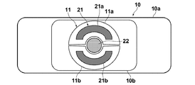
- FIG. 2 is a view of the ultrasonic probe 10 as viewed from the side where the optical wiring 21 and the electrical wiring 22 are connected.
- the ultrasonic probe 10 has an optical connector (optical wiring connection portion) 11 on the upper surface of the grip portion 10b.
- the optical connector 11 removably connects the optical wiring 21.
- the optical wiring 21 is divided into a plurality of optical wirings. In the example of the figure, the optical wiring 21 is divided into two, an optical wiring 21a and an optical wiring 21b.
- the optical connector 11 is divided into an optical connector 11a and an optical connector 11b.
- the optical connector 11a is connected to the optical wiring 21a, and the optical connector 11b is connected to the optical wiring 21b.
- the optical connectors 11a and 11b are arranged so as to surround a portion where the electric wiring 22 is fixed.
- the optical connectors 11a and 11b are arranged so as to sandwich the electric wiring 22 from the upper side and the lower side of the drawing.
- the optical wiring 21 is arranged so as to surround the electrical wiring 22 with the electrical wiring 22 as the center.
- Each of the optical wirings 21a and 21b is configured as a bundle fiber in which, for example, several tens of optical fibers are bundled.
- the optical wiring 21 and the electrical wiring 22 appear as one wiring (cable) from the outside.
- the optical wiring 21 and the electrical wiring 22 are flexible.
- the plurality of divided optical wirings correspond to the respective wavelengths. You may let them.
- the optical wiring 21 is divided into two, one optical wiring corresponds to one of the two wavelengths, and the other optical wiring corresponds to the other wavelength. You can also.
- the optical wiring 21 is divided into two optical wirings 21a and 21b as shown in FIG. The light of 750 nm may be guided, and the optical wiring 21 b may guide the light having a wavelength of 800 nm.
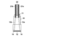
- FIG. 3A is a cross-sectional view in the side surface direction of the ultrasonic probe 10, and FIG. 3B is a cross-sectional view in the front direction.
- the ultrasonic probe 10 has an ultrasonic transducer 12 on the lower surface of the array unit 10a.
- a light irradiation unit 14 is disposed on both sides of the ultrasonic transducer 12.
- the light irradiation unit 14 may include a light diffusion layer that diffuses light.
- the ultrasonic probe 10 includes another optical wiring (intra-probe optical wiring) 13 that guides light to be irradiated to the subject from the optical connector 11 to the light irradiation unit 14.
- the ultrasonic probe 10 has in-probe optical wirings 13a and 13b corresponding to the optical wirings 21a and 21b divided into two.
- the intra-probe optical wires 13a and 13b include the same number of optical fibers as the optical fibers included in the optical wires 21a and 21b configured as bundle fibers, for example.
- the optical fibers included in the optical wirings 21a and 21b are connected to the corresponding optical fibers of the in-probe optical wirings 13a and 13b by the optical connectors 11a and 11b.
- a some optical fiber is arrange
- the laser beam is emitted from the tip of each optical fiber, so that the subject is irradiated with the laser beam from the light irradiation unit 14.
- optical wiring 21 and the electrical wiring 22 may be applied to the optical wiring 21 and the electrical wiring 22.
- the optical wiring 21 can be detached from the optical connector 11 and the optical wiring 21 can be separated from the ultrasonic probe 10.
- the other end side of the optical wiring 21 is removed from the connector of the light source unit 31, and the optical wiring 21 is separated from the light source unit 31.
- one end of the newly prepared optical wiring 21 is connected to the optical connector 11 of the ultrasonic probe 10, and the other end is connected to the light source unit 31.
- the electrical wiring 22 is fixed to the probe body, while the optical wiring 21 has both the ultrasonic probe 10 side and the light source unit 31 as a connector structure, and can be detached from the probe body.
- the optical wiring 21 can be separated from the ultrasonic probe 10 by removing the optical wiring 21 from the optical connector 11.
- the optical wiring 21 since only the optical wiring 21 can be removed, it is not necessary to replace the probe main body when a failure occurs in the optical wiring 21.
- an optical fiber having a small diameter is used for the optical wiring 21, it is considered that disconnection is likely to occur.
- it is sufficient to replace only the optical wiring 21 each time. The cost required for repair can be reduced as compared with the case where the entire body needs to be replaced.
- the ultrasonic probe 10 a has a light guide plate 15.
- the light guide plate 15 guides light from the optical connector 11 to the light irradiation unit 14.
- the light guide plate 15 includes a light guide plate 15a corresponding to the optical wiring 21a and a light guide plate 15b corresponding to the optical wiring 21b.
- the light guide plate 15 emits light from the surface facing the light irradiation unit 14.
- the light guide plates 15a and 15b have fan-shaped spread shapes in accordance with the light irradiation area.
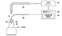
- FIG. 5 shows a photoacoustic image diagnostic apparatus including an ultrasonic probe according to the second embodiment of the present invention.
- the ultrasonic probe 10 of this embodiment further includes a connection detection unit 16 that detects that the optical wiring 21 is connected to the optical connector 11.
- a connection detection switch that changes on / off according to whether or not the optical wiring 21 is connected to the optical connector 11 can be used.
- the connection detection switch is turned off when the optical wiring 21 is not connected to the optical connector 11 and turned on when the optical wiring 21 is correctly connected to the optical connector 11.
- the connection detection unit 16 is provided on the optical connector 11 side, but the connection detection unit 16 may be provided on the optical wiring 21 side.
- the ultrasonic unit 32 in the present embodiment includes an optical connection state determination unit 33.
- the optical connection state determination unit 33 determines whether or not the optical wiring 21 is connected to the optical connector 11 based on a signal from the connection detection unit 16. For example, the optical connection state determination unit 33 determines that the optical wiring 21 is not connected to the optical connector 11 if the connection detection switch of the connection detection unit 16 is off, and if the connection detection switch is on, the optical connector 11 is determined that the optical wiring 21 is correctly connected. When determining that the optical wiring 21 is not connected to the optical connector 11, the optical connection state determination unit 33 displays a warning indicating that the optical wiring is not correctly connected on a display monitor (not shown). Further, light emission from the light source unit 31 is suppressed.
- the optical connection state determination unit 33 may be provided on the light source unit 31 side.
- connection detection unit 16 is a connection detection switch.
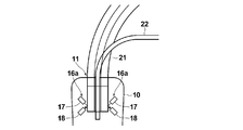
- FIG. 6A and FIG. 6B show a portion of a connection detection unit in an ultrasonic probe according to a modification.
- a photo reflector (reflective photo interrupter) 16 a is used for the connection detector 16.
- the photo reflector 16 a includes a light emitting unit 17 that emits light and a light detection unit 18 that detects light emitted from the light emitting unit 17.
- the light detection unit 18 is disposed at a position where the light emitted from the light emission unit 17 does not directly enter. As shown in FIG. 6A, when the optical wiring 21 is not connected to the optical connector 11, the light emitted from the light emitting unit 17 does not go to the light detecting unit 18, and the light detecting unit 18 does not detect the light.
- FIG. 6B shows a state in which the optical wiring 21 is connected to the optical connector 11.
- the optical wiring 21 When the optical wiring 21 is correctly connected to the optical connector 11, the light emitted from the light emitting portion 17 is reflected by the optical connector 11, and the light detecting portion 18 detects the reflected light.
- the light detection signal of the light detection unit 18 is input to the optical connection state determination unit 33 (FIG. 5).
- the optical connection state determination unit 33 determines that the optical wiring 21 is connected to the optical connector 11 when outputting a light detection signal indicating that the light detection unit 18 has detected light. When no light is detected by the light detection unit 18, it is determined that the optical wiring 21 is not connected to the optical connector 11.
- the photo reflector 16a is used for the connection detection unit 16.
- the connection state of the optical wiring 21 can be determined using a photo interrupter (transmission type photo interrupter).
- the light detection unit 18 is arranged at a position where the light emitted from the light emission unit 17 directly enters, and the optical connector 11 emits from the light emission unit 17 when the optical wiring 21 is connected to the optical connector 11. You just have to block the light.
- the optical connection state determination unit 33 determines that the optical wiring 21 is not connected to the optical connector 11 when the light detection unit 18 outputs a light detection signal indicating that the light has been detected. When no light is detected by the light detection unit 18, it may be determined that the optical wiring 21 is connected to the optical connector 11.
- the connection detector 16 can be used to determine the connection state of the optical wiring 21. For example, by giving a warning indicating that the optical wiring 21 is not connected to the ultrasonic probe 10, the user can know that the optical wiring 21 is not correctly attached. Further, by suppressing the light output of the light source unit 31 when the optical wiring 21 is not correctly attached to the ultrasonic probe 10, it is possible to avoid a situation where a laser is output in the atmosphere or the like.
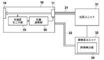
- FIG. 7 shows a photoacoustic image diagnostic apparatus including the probe according to the third embodiment of the present invention.
- the ultrasonic probe 10 includes a light intensity monitor unit 19 and a position adjustment unit 50.
- the position adjustment unit 50 adjusts the relative positional relationship between the optical wiring 21 attached to the optical connector 11 and the light receiving portion of the optical connector 11 that receives the light guided by the optical wiring 21.
- the position adjustment unit 50 adjusts the relative positional relationship between the optical wiring 21 and the light receiving portion of the optical connector 11 by, for example, displacing the position of the light receiving portion of the optical connector 11. By using such a position adjusting unit 50, the optical coupling portion can be accurately aligned.
- the light intensity monitor unit 19 monitors the intensity of light guided from the optical wiring 21 through the light receiving portion of the optical connector 11 to the probe body side.
- the light intensity monitor unit 19 monitors the light intensity in an optical member that guides light from the optical connector 11 to the light irradiation unit 14, for example.
- the intra-probe optical wiring 13 (FIGS. 3A and 3B) is used for light guiding between the optical connector 11 and the light irradiation unit 14, the intensity of light in the intra-probe optical wiring 13 is monitored.
- the light intensity monitored by the light intensity monitoring unit 19 is maximized.
- the light intensity monitored by the light intensity monitor unit 19 decreases when the positional relationship between the two is deviated.
- the position adjusting unit 50 adjusts the positional relationship between the optical wiring 21 and the light receiving portion of the optical connector 11 based on, for example, information on the light intensity monitored by the light intensity monitoring unit 19.
- the position adjustment unit 50 acquires information on the light intensity at each position while changing the positional relationship between the optical wiring 21 and the light receiving portion of the optical connector 11, for example, so that the monitored light intensity is maximized.
- the positional relationship between the optical wiring 21 and the light receiving portion of the optical connector 11 is adjusted.
- the light intensity monitor unit 19 compares the monitored light intensity with a predetermined threshold value. When the optical wiring 21 is broken, it is considered that the light intensity monitored by the light intensity monitor unit 19 decreases. When the monitored light intensity is smaller than the threshold value, the light intensity monitoring unit 19 outputs a signal indicating that the optical wiring 21 may be disconnected.
- the ultrasonic unit 32 is provided with a disconnection detector 34. When the light intensity monitoring unit 19 outputs a signal indicating that the optical wiring 21 may be disconnected, the disconnection detecting unit 34 suppresses the light output from the light source unit 31.
- the disconnection detector 34 may compare the monitored light intensity with the threshold value.
- the disconnection detection unit 34 may be provided in the light source unit 31.
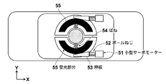
- FIG. 8 shows a configuration example of the position adjustment unit 50.
- the position adjustment unit 50 includes a servo motor 51, a ball screw 52, a push plate 53, and a spring 54.
- a light receiving portion (optical member on the probe main body side) 55 of the optical connector 11 is biased in the Y direction by a spring 54.
- the pressing plate 53 is formed such that the thickness in the Y direction changes according to the position in the X direction.
- the ball screw 52 displaces the push plate 53 in the X direction.
- a ball screw 52 is attached to the output shaft of the servo motor 51, and the push plate 53 is displaced in the X direction according to the rotation of the servo motor 51.
- the pressing plate 53 When the pressing plate 53 is displaced in the X direction, the position of the light receiving portion 55 in the Y direction is displaced, and the relative positional relationship between the optical wiring 21 and the light receiving portion 55 can be adjusted.
- the set of the servo motor 51, the ball screw 52, and the push plate 53 is provided corresponding to each of the plurality of divided optical wirings, and the position can be adjusted by each of the plurality of divided optical wirings. is there.
- the ultrasonic probe 10 includes the position adjusting unit 50.
- the position adjustment unit 50 By using the position adjustment unit 50, the position between the two can be adjusted.
- the amount of light guided from the optical wiring 21 to the probe side is monitored using the light intensity monitor unit 19.
- the amount of light applied to the subject can be maximized by adjusting the position so that the amount of light monitored by the light intensity monitor unit 19 is maximized.
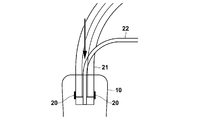
- the ultrasonic probe 10 further includes a protective cover 20 that covers an attachment portion of the optical wiring 21 in the optical connector 11.
- the protective cover 20 is movable and is closed so as to cover a portion where the optical wiring 21 is attached to the optical connector 11 when the optical wiring 21 is not attached to the optical connector 11. .
- FIG. 9B shows a state in which the optical wiring 21 is attached to the optical connector 11.
- the protective cover 20 falls to the main body side and opens.
- the protective cover 20 is biased using a spring or the like, and is closed when the optical wiring 21 is pulled out from the optical connector 11.
- the mounting portion of the optical wiring 21 in the optical connector 11, particularly the light receiving portion of the optical connector 11 is exposed. It is possible to prevent foreign matter from being mixed into the optical connector 11 and reduction in the amount of light due to contamination of the light receiving portion.
- the present invention is not limited to this.
- the light source unit 31 emits light of a plurality of wavelengths and when the divided optical wiring corresponds to each wavelength, the light intensity of each wavelength monitored by the light intensity monitor unit 19 is equal.
- the relative positional relationship between the optical wiring corresponding to each wavelength and the light receiving portion of the optical connector 11 may be adjusted. In such a case, even when the intensity of the light emitted from the light source unit 31 differs for each wavelength, the light intensity of the light of each wavelength irradiated on the subject can be made uniform.
- the ultrasonic probe of the present invention is not limited to the above embodiments, and various modifications and changes are made to the configuration of the above embodiments. What has been done is also included in the scope of the present invention.
- a connector may be provided on the probe body side so that the electrical wiring can be removed from the probe body.
Landscapes
- Life Sciences & Earth Sciences (AREA)
- Health & Medical Sciences (AREA)
- Physics & Mathematics (AREA)
- Heart & Thoracic Surgery (AREA)
- Molecular Biology (AREA)
- Pathology (AREA)
- Engineering & Computer Science (AREA)
- Biomedical Technology (AREA)
- Acoustics & Sound (AREA)
- Medical Informatics (AREA)
- Biophysics (AREA)
- Surgery (AREA)
- Animal Behavior & Ethology (AREA)
- General Health & Medical Sciences (AREA)
- Public Health (AREA)
- Veterinary Medicine (AREA)
- Ultra Sonic Daignosis Equipment (AREA)
Abstract
超音波プローブは、被検体に光を照射する光照射部と、被検体からの超音波の検出が可能な超音波振動子とを含む。光コネクタは、光照射部から照射されるべき光を導光する光配線を取り外し可能に接続する。
Description
本発明は、超音波プローブに関し、更に詳しくは光音響イメージングに用いられる超音波プローブに関する。
生体内部の状態を非侵襲で検査できる画像検査法の一種として、超音波検査法が知られている。超音波検査では、超音波の送信及び受信が可能な超音波プローブ(探触子)を用いる。超音波プローブから被検体(生体)に超音波を送信させると、その超音波は生体内部を進んでいき、組織界面で反射する。超音波プローブでその反射音波を受信し、反射超音波が超音波プローブに戻ってくるまでの時間に基づいて距離を計算することで、内部の様子を画像化することができる。
また、光音響効果を利用して生体の内部を画像化する光音響イメージングが知られている。一般に光音響イメージングでは、パルスレーザ光を生体内に照射する。生体内部では、生体組織がパルスレーザ光のエネルギーを吸収し、そのエネルギーによる断熱膨張により超音波(光音響信号)が発生する。この光音響信号を超音波プローブなどで検出し、検出信号に基づいて光音響画像を構成することで、光音響信号に基づく生体内の可視化が可能である。
光音響イメージングでは、レーザ光源からの光を超音波プローブまで導光し、超音波プローブからレーザ光を照射することがある。光照射部を有する超音波プローブは、例えば特許文献1に記載されている。特許文献1では、複数の光ファイバを用いて、レーザ光源からの光を超音波プローブまで導光する。複数の光ファイバと、超音波プローブに設けられた電極などに接続される電気ケーブルとは、被覆によってまとめられ、1本のケーブルとして超音波プローブに取り付けられている。1本のケーブルはケーブルの他端で分岐し、複数の光ファイバは例えばレーザ光源の光出射端に接続され、電気ケーブルは例えば信号の送受信回路に接続される。一般に、ケーブルの他端はコネクト構造を有し、超音波プローブはコネクタ部分で本体(超音波ユニット及び光源)側と着脱可能になっている。
ところで、医師などの操作者は、プローブを様々な角度や方向に動かすことがあり、プローブと超音波ユニット及び光源とを接続するケーブルには柔軟性(可撓性)が求められる。一般に、径が太い光ファイバは可撓性が低いため、ケーブルには細い光ファイバを用いる方が有利である。しかし、細い光ファイバは、外力が加わった際に断線する可能性が高く、光ファイバが断線したときは交換が必要にある。このとき、従来のプローブではケーブルがプローブに直に取り付けられているため、ケーブル部分のみを交換することはできず、プローブ本体ごと交換する必要があった。
本発明は、上記に鑑み、光源からの光をプローブ本体まで導光する部分に故障が生じたときでも、プローブ本体ごと交換する必要をなくした超音波プローブを提供することを目的とする。
上記目的を達成するために、本発明は、被検体に光を照射する光照射部と、少なくとも被検体からの超音波の検出が可能な超音波振動子と、前記光照射部から照射されるべき光を導光する光配線を取り外し可能に接続する光配線接続部を備える超音波プローブを提供する。
本発明の超音波プローブが、一端がプローブ本体に固定され、他端にコネクタを有する電気配線を更に備える構成を採用してもよい。
本発明では、前記光配線が複数の光配線に分割されており、前記光配線接続部が、前記分割された各光配線と接続するための複数の光コネクタを含む構成を採用できる。
本発明では、前記複数の光コネクタが、前記電気配線が固定された部分を取り囲むように配置される構成とすることができる。
前記分割された各光配線は、複数の光ファイバを含むバンドルファイバを有していてもよい。
本発明の超音波プローブは、前記光配線接続部から前記光照射部まで光を導光する別の光配線を更に備えていてもよい。あるいは、前記光配線接続部から前記光照射部まで光を導光する導光板を更に備えていてもよい。
本発明の超音波プローブは、前記光配線接続部に、前記光配線が接続されていることを検出する接続検出部を更に備える構成を採用することができる。
前記接続検出部が、前記光配線接続部に光配線が接続されているか否かに応じてオン・オフが変化する接続検出スイッチを含むものとしてもよい。あるいは、前記接続検出部が、光を出射する光出射部と、該光出射部から出射した光を検出する光検出部とを含み、前記光配線接続部に光配線が接続されているか否かに応じて該光検出部での光検出状態が変化するフォトインタラプタ又はフォトリフレクタを含むものとしてもよい。
前記被検体に対して照射される光が相互に異なる複数の波長の光を含むとき、前記分割された各光配線を各波長に対応させてもよい。この場合、超音波プローブが、前記光配線接続部に対して取り付けられた分割された各光配線と、各光配線により導光された光を受光する前記光配線接続部の受光部分との間の相対的な位置関係を調整する位置調整部と、前記光配線から前記受光部分を通ってプローブ本体側に導光された各波長の光の強度をモニタする光強度モニタ部とを更に備える構成とし、前記位置調整部が、前記光強度モニタ部でモニタされる各波長の光強度が等しくなるように、各波長に対応した光配線と前記受光部分との間の相対的な位置関係を調整するようにしてもよい。
本発明の超音波プローブは、前記光配線接続部に対して取り付けられた前記光配線と、該光配線により導光された光を受光する前記光配線接続部の受光部分との間の相対的な位置関係を調整する位置調整部を更に備える構成を採用することができる。
また、本発明の超音波プローブは、前記光配線から前記受光部分を通ってプローブ本体側に導光された光の強度をモニタする光強度モニタ部を更に備える構成としてもよい。
前記光強度モニタ部が、モニタした光強度と所定のしきい値とを比較し、光強度が所定のしきい値よりも小さいと判断すると、前記光配線が断線している可能性がある旨を示す信号を出力することとしてもよい。
本発明の超音波プローブは、前記光配線接続部における前記光配線の取り付け部分を覆う保護カバーを更に備えていてもよい。保護カバーは、前記光配線取り付け部に前記光配線が取り付けられていない状態では前記光配線の取り付け部分を覆うように閉じ、前記光配線接続部に前記光配線を押し当てると開くことが好ましい。
本発明の超音波プローブは、光照射部から照射されるべき光を導光する光配線を取り外し可能に接続する光配線接続部を備える。光配線に故障が生じたときは、光配線接続部から光配線を切り離すことができ、光配線のみの交換が可能になる。このため、光配線に故障が生じたときに、プローブ本体ごと交換する必要がなくなる。
以下、図面を参照し、本発明の実施の形態を詳細に説明する。図1は、本発明の第1実施形態の超音波プローブ(超音波探触子)を含む光音響画像診断装置を示す。光音響画像診断装置は、超音波プローブ10、光源ユニット31、及び超音波ユニット32を備える。超音波プローブ10は、被検体に光を照射する光照射部と、少なくとも被検体からの超音波が検出可能な超音波振動子とを有する。光源ユニット31は、例えばパルスレーザ光を生成するレーザユニットであり、超音波プローブ10から被検体に対して照射すべき光を生成する。超音波ユニット32は、超音波プローブ10が検出した超音波信号に基づいて、光音響画像の生成を行う。
超音波プローブ10は、例えば超音波振動子が一次元的に配列されたアレイ部10aと、操作者がプローブを使用する際に握る握り部10bとを有している。超音波プローブ10は、光配線21を介して光源ユニット31と接続し、電気配線22を介して超音波ユニット32と接続する。光源ユニット31で生成されたパルスレーザ光は、光配線21により超音波プローブ10に導光され、超音波プローブ10の光照射部から被検体に照射される。超音波プローブ10が検出した超音波信号は、電気配線22により超音波ユニット32に伝送され、超音波ユニット32で処理される。
光配線21の両端は、それぞれ光源ユニット31及び超音波プローブ10と接続するための光コネクタを有している。光源ユニット31及び超音波プローブ10は、それぞれ光配線21と接続するための光コネクタを有している。光配線21は、光源ユニット31及び超音波プローブ10のそれぞれに対して着脱可能になっている。電気配線22の超音波ユニット32側の端は超音波ユニット32と接続するためのコネクタを有しており、超音波ユニット32は、電気配線22と接続するためのコネクタを有している。一方、電気配線22の超音波プローブ10側の端はプローブ本体に固定されている。電気配線22は、超音波ユニット32に対して着脱可能になっている。
図2は、超音波プローブ10を光配線21及び電気配線22が接続される側から見た図である。超音波プローブ10は、握り部10bの上側の面に光コネクタ(光配線接続部)11を有する。光コネクタ11は、光配線21を取り外し可能に接続する。光配線21は、複数の光配線に分割されている。同図の例では、光配線21は光配線21aと光配線21bとの2つに分割されている。これに合わせて、光コネクタ11は、光コネクタ11aと光コネクタ11bとに二分割されている。光コネクタ11aは光配線21aと接続し、光コネクタ11bは光配線21bと接続する。
光コネクタ11a、11bは、電気配線22が固定された部分を取り囲むように配置される。図2の例では、光コネクタ11a、11bが、紙面上側と下側とから電気配線22を挟み込むように配置されている。光配線21は、電気配線22を中心として、電気配線22を取り囲むように配置される。光配線21a及び21bは、それぞれ例えば数十本の光ファイバが束ねられたバンドルファイバとして構成される。光配線21及び電気配線22は、外側からは1本の配線(ケーブル)として見える。光配線21及び電気配線22には、可撓性を有している。
ここで、被検体に対して照射される光が相互に異なる複数の波長を含むとき、すなわち光源ユニット31が複数の波長の光を出射するとき、分割された複数の光配線を各波長に対応させてもよい。例えば光源ユニット31が2つの波長の光を出射するとき、光配線21を二分割し、一方の光配線を2つの波長のうちの一方に対応させ、他方の光配線を他方の波長に対応させることもできる。具体的に、光源ユニット31が波長750nmの光と波長800nmの光とを出射するとき、図2に示すように光配線21を2つの光配線21a、21bに二分割し、光配線21aが波長750nmの光を導光し、光配線21bが波長800nmの光を導光するようにしてもよい。
図3Aは、超音波プローブ10の側面方向の断面図であり、図3Bは、正面方向の断面図である。図3Aに示すように、超音波プローブ10は、アレイ部10aの下側の面に超音波振動子12を有している。超音波振動子12の両脇には、光照射部14が配置される。光照射部14は、光を拡散させる光拡散層を含んでいてもよい。超音波プローブ10は、光コネクタ11から光照射部14まで、被検体に照射すべき光を導光する別の光配線(プローブ内光配線)13を有する。超音波プローブ10は、二分割された光配線21a、21bに対応して、プローブ内光配線13a、13bを有する。
プローブ内光配線13a、13bは、それぞれ、例えばバンドルファイバとして構成される光配線21a、21bが有する光ファイバの数と同数の光ファイバを含む。光配線21a、21bに含まれる各光ファイバは、光コネクタ11a、11bで、プローブ内光配線13a、13bの対応する光ファイバに接続される。図3Bに示すように、複数の光ファイバは、照明エリアに対応して光コネクタ11から扇状に広がるように配置される。各光ファイバの先端からレーザ光が出射することで、光照射部14から、被検体にレーザ光が照射される。
超音波プローブの使用中、光配線21及び電気配線22にはねじれやひねりなどの外力が加わることがある。特に、光配線21に細い光ファイバなどを用いる場合、光ファイバに外力が加わることで光ファイバに断線が生じることが考えられる。一方、電気配線22は、光配線21に比べれば断線を起こす可能性は低い。光配線21に断線が生じた場合、光配線21を光コネクタ11から取り外し、光配線21を超音波プローブ10から分離することができる。光配線21の他端側も同様に、光源ユニット31のコネクタから取り外し、光配線21を光源ユニット31から分離する。そして、新たに用意した光配線21の一端を超音波プローブ10の光コネクタ11に接続し、他端を光源ユニット31に接続する。このようにすることで、電気配線22はそのままに、光配線21のみを取り換えることができる。
本実施形態では、電気配線22はプローブ本体に固定しておく一方、光配線21は、超音波プローブ10側と光源ユニット31との双方をコネクタ構造とし、プローブ本体から取り外し可能とする。光配線21に断線などの故障が生じた場合、光配線21を光コネクタ11から取り外すことで、光配線21を超音波プローブ10から分離できる。本実施形態では、光配線21のみを取り外すことができるため、光配線21に故障が生じたときに、プローブ本体を取り換える必要がなくなる。特に、光配線21に径が細い光ファイバを用いると、断線が生じやすくなることが考えられるが、仮に頻繁に断線が発生しても、その都度、光配線21のみを交換してやればよく、プローブ本体ごと交換が必要な場合に比して、修理に要する費用を低減できる。
なお、上記では、超音波プローブ10内で光コネクタ11から光照射部14までの導光にプローブ内光配線13を用いる例を説明したが、この部分の導光に導光板を用いることもできる。図4A及び図4Bは、それぞれ導光板を用いる場合の超音波プローブの側面及び正面の断面図である。超音波プローブ10aは、導光板15を有する。導光板15は、光コネクタ11から光照射部14まで光を導光する。導光板15は、光配線21aに対応する導光板15aと、光配線21bに対応する導光板15bとを有する。導光板15は、光照射部14に面する面から光を出射する。導光板15a、15bは、光の照射エリアに合わせて扇状の広がった形状を有する。
次いで、本発明の第2実施形態を説明する。図5は、本発明の第2実施形態の超音波プローブを含む光音響画像診断装置を示す。本実施形態の超音波プローブ10は、光配線21が光コネクタ11に接続されていることを検出する接続検出部16を更に備える。接続検出部16には、例えば光コネクタ11に光配線21が接続されているか否かに応じてオン・オフが変化する接続検出スイッチを用いることができる。接続検出スイッチは、例えば光コネクタ11に光配線21が接続されていないときはオフで、光コネクタ11に光配線21が正しく接続されるとオンになる。図5では、接続検出部16を光コネクタ11側に設けているが、接続検出部16を光配線21側に設けることも可能である。
本実施形態における超音波ユニット32は、光接続状態判断部33を含む。光接続状態判断部33は、接続検出部16からの信号に基づいて、光コネクタ11に光配線21が接続されているか否かを判断する。例えば光接続状態判断部33は、接続検出部16の接続検出スイッチがオフであれば、光コネクタ11に光配線21が接続されていないと判断し、接続検出スイッチがオンであれば、光コネクタ11に光配線21が正しく接続されていると判断する。光接続状態判断部33は、光コネクタ11に光配線21が接続されていないと判断すると、図示しない表示モニタなどに、光配線が正しく接続されていない旨を示す警告を表示する。また、光源ユニット31からの光出射を抑制する。光接続状態判断部33は、光源ユニット31側に設けられていてもよい。
上記では、接続検出部16が接続検出スイッチであるとしたが、これには限定されない。図6A及び図6Bは、変形例の超音波プローブにおける接続検出部の部分を示す。この例では、接続検出部16に、フォトリフレクタ(反射型フォトインタラプタ)16aが用いられている。フォトリフレクタ16aは、光を出射する光出射部17と、光出射部17から出射した光を検出する光検出部18とを含む。光検出部18は、光出射部17から出射した光が直接に入射しない位置に配置されている。図6Aに示すように、光コネクタ11に光配線21が接続されていないとき、光出射部17から出射した光は光検出部18には向かわず、光検出部18は光を検出しない。
図6Bは、光配線21が光コネクタ11に接続された状態を示す。光コネクタ11に光配線21が正しく接続されると、光出射部17を出射した光は光コネクタ11で反射し、光検出部18はその反射光を検出する。光検出部18の光検出信号は、光接続状態判断部33(図5)に入力される。光接続状態判断部33は、光検出部18が光を検出した旨の光検出信号を出力すると、光コネクタ11に光配線21が接続されたと判断する。光検出部18で光が検出されないとき、光コネクタ11に光配線21が接続されていないと判断する。
なお、図6A及び図6Bでは、接続検出部16にフォトリフレクタ16aを用いたが、フォトインタラプタ(透過型フォトインタラプタ)を用いて光配線21の接続状態を判断することも可能である。その場合、光検出部18を、光出射部17から出射した光が直接入射する位置に配置し、光コネクタ11に光配線21が接続されたときに、光コネクタ11が光出射部17から出射した光を遮るようにしておけばよい。フォトインタラプタを用いた場合、光接続状態判断部33は、光検出部18が光を検出した旨の光検出信号を出力するとき、光コネクタ11に光配線21が接続されていないと判断し、光検出部18で光が検出されないとき、光コネクタ11に光配線21が接続されたと判断すればよい。
本実施形態では、接続検出部16を用いて、光配線21の接続状態を判断できるようにしている。例えば光配線21が超音波プローブ10に接続されていない旨を示す警告を行うようにすることで、ユーザは、光配線21が正しく取り付けられていないことを知ることができる。また、光配線21が超音波プローブ10に正しく取り付けられていないときに、光源ユニット31の光出力を抑制することで、大気中などにレーザが出力される事態を避けることができる。
続いて、本発明の第3実施形態を説明する。図7は、本発明の第3実施形態のプローブを含む光音響画像診断装置を示す。本実施形態では、超音波プローブ10が、光強度モニタ部19と位置調整部50とを有する。位置調整部50は、光コネクタ11に対して取り付けられた光配線21と、光配線21により導光された光を受光する光コネクタ11の受光部分との間の相対的な位置関係を調整する。位置調整部50は、例えば光コネクタ11の受光部分の位置を変位させることで、光配線21と光コネクタ11の受光部分との間の相対的な位置関係を調整する。このような位置調整部50を用いることで、光結合部分を精度よく位置合せすることができる。
光強度モニタ部19は、光配線21から光コネクタ11の受光部分を通ってプローブ本体側に導光された光の強度をモニタする。光強度モニタ部19は、例えば光コネクタ11から光照射部14まで光を導光する光学部材における光の強度をモニタする。例えば光コネクタ11から光照射部14までの間の導光にプローブ内光配線13(図3A及び図3B)が用いられる場合、プローブ内光配線13における光の強度をモニタする。光コネクタ11の受光部分と光配線21とが正確に位置合せされているとき、光強度モニタ部19がモニタする光強度は最大となると考えられる。一方、両者の位置関係にずれが生じていると、光強度モニタ部19がモニタする光強度は減少するものと考えられる。
位置調整部50は、例えば光強度モニタ部19でモニタされた光強度の情報に基づいて、光配線21と光コネクタ11の受光部分との間の位置関係を調整する。位置調整部50は、例えば光配線21と光コネクタ11の受光部分との間の位置関係を変化させつつ、各位置における光強度の情報を取得し、モニタされた光強度が最大となるように、光配線21と光コネクタ11の受光部分との間の位置関係を調整する。
また、光強度モニタ部19は、モニタした光強度と、所定のしきい値とを比較する。光配線21に断線が生じているような場合、光強度モニタ部19がモニタする光強度は減少すると考えられる。光強度モニタ部19は、モニタした光強度がしきい値よりも小さいときは、光配線21が断線している可能性がある旨を示す信号を出力する。超音波ユニット32には、断線検出部34が設けられている。断線検出部34は、光強度モニタ部19が光配線21が断線している可能性がある旨を示す信号を出力すると、光源ユニット31からの光出力を抑制させる。モニタされた光強度としきい値との比較は、断線検出部34で行ってもよい。また、断線検出部34は、光源ユニット31に設けられていてもよい。
図8は、位置調整部50の構成例を示す。位置調整部50は、サーボモータ51、ボールねじ52、押板53、及びばね54を有する。光コネクタ11の受光部分(プローブ本体側の光学部材)55は、ばね54によりY方向に付勢されている。押板53は、Y方向の厚みがX方向の位置に応じて変化するように形成されている。ボールねじ52は、押板53をX方向に変位させる。サーボモータ51の出力軸には、ボールねじ52が取り付けられており、押板53はサーボモータ51の回転に従ってX方向に変位する。押板53がX方向に変位することで、受光部分55のY方向の位置が変位し、光配線21と受光部分55との相対的な位置関係が調整できる。サーボモータ51、ボールねじ52、及び押板53のセットは、分割された複数の光配線のそれぞれに対応して設けられており、分割された複数の光配線のそれぞれで、位置調整が可能である。
本実施形態では、超音波プローブ10が位置調整部50を備えている。光コネクタ11を用いて超音波プローブ10側で光配線21を取り外し可能に構成した場合、光配線21を取り付けた際に、光配線21と光コネクタ11の受光部分との間に位置ずれが生じる可能性がある。位置調整部50を用いることで、両者間の位置を調整することができる。
また、本実施形態では、光強度モニタ部19を用いて、光配線21からプローブ側に導光された光の量をモニタする。例えば、光強度モニタ部19でモニタされた光の量が最大となるように位置調整を行うことで、被検体に照射する光の量を最大化することができる。また、光強度モニタ部19でモニタした光量に基づいて、光配線21に断線が生じているか否かの判断を行うことができる。光配線21の断線が疑われるような場合には、光源ユニット31からの光出力を抑制するようにするとよい。
引き続き、本発明の第4実施形態を説明する。図9A及び図9Bは、本発明の第4実施形態の超音波プローブにおける光コネクタ11付近を示す。本実施形態では、超音波プローブ10が、光コネクタ11における光配線21の取り付け部分を覆う保護カバー20を更に備える。保護カバー20は可動式になっており、光コネクタ11に光配線21が取り付けられていない状態では、図9Aに示すように、光コネクタ11における光配線21の取り付け部分を覆うように閉じている。
図9Bは、光コネクタ11に光配線21を取り付けた状態を示す。保護カバー20は、光コネクタ11に光配線21を押し当てると本体側に倒れて開く。保護カバー20は、ばねなどを用いて付勢されており、光コネクタ11から光配線21が引き抜かれると、閉じるようになっている。このような保護カバー20を用いることで、光コネクタ11に光配線21が接続されていないときに、光コネクタ11における光配線21の取り付け部分、特に光コネクタ11の受光部分がむき出しになることを防止でき光コネクタ11への異物の混入や、受光部分の汚れに起因する光量の低下などを防止できる。
なお、第3実施形態では、光強度モニタ部19がモニタした光強度が最大となるように位置調整を行う例を説明したが、これには限定されない。例えば光源ユニット31が複数の波長の光を出射する場合で、かつ、分割された光配線が各波長に対応するような場合に、光強度モニタ部19でモニタされる各波長の光強度が等しくなるように、各波長に対応した光配線と光コネクタ11の受光部分との相対的な位置関係を調整してもよい。そのようにする場合、光源ユニット31から出射した光の強度が波長ごとに異なるときでも、被検体に照射される各波長の光の光強度を揃えることができる。
以上、本発明をその好適な実施形態に基づいて説明したが、本発明の超音波プローブは、上記実施形態にのみ限定されるものではなく、上記実施形態の構成から種々の修正及び変更を施したものも、本発明の範囲に含まれる。例えば、電気配線についても、プローブ本体側にコネクタを設け、プローブ本体から電気配線を取り外せるようにしてもよい。
Claims (17)
- 被検体に光を照射する光照射部と、
少なくとも被検体からの超音波の検出が可能な超音波振動子と、
前記光照射部から照射されるべき光を導光する光配線を取り外し可能に接続する光配線接続部を備えた超音波プローブ。 - 一端がプローブ本体に固定され、他端にコネクタを有する電気配線を更に備えたことを特徴とする請求項1に記載の超音波プローブ
- 前記光配線が複数の光配線に分割されており、前記光配線接続部が、前記分割された各光配線と接続するための複数の光コネクタを含むことを特徴とする請求項2に記載の超音波プローブ。
- 前記複数の光コネクタが、前記電気配線が固定された部分を取り囲むように配置されることを特徴とする請求項3に記載の超音波プローブ。
- 前記分割された各光配線が、複数の光ファイバを含むバンドルファイバを有することを特徴とする請求項3に記載の超音波プローブ。
- 前記光配線接続部から前記光照射部まで光を導光する別の光配線を更に備えることを特徴とする1に記載の超音波プローブ。
- 前記光配線接続部から前記光照射部まで光を導光する導光板を更に備えることを特徴とする請求項1に記載の超音波プローブ。
- 前記光配線接続部に、前記光配線が接続されていることを検出する接続検出部を更に備える請求項1に記載の超音波プローブ。
- 前記接続検出部が、前記光配線接続部に光配線が接続されているか否かに応じてオン・オフが変化する接続検出スイッチを含むことを特徴とする請求項8に記載の超音波プローブ。
- 前記接続検出部が、光を出射する光出射部と、該光出射部から出射した光を検出する光検出部とを含み、前記光配線接続部に光配線が接続されているか否かに応じて該光検出部での光検出状態が変化するフォトインタラプタ又はフォトリフレクタを含むことを特徴とする請求項8に記載の超音波プローブ。
- 前記被検体に対して照射される光が相互に異なる複数の波長の光を含み、前記分割された各光配線が各波長に対応していることを特徴とする請求項3に記載の超音波プローブ。
- 前記光配線接続部に対して取り付けられた前記分割された各光配線と、各光配線により導光された光を受光する前記光配線接続部の受光部分との間の相対的な位置関係を調整する位置調整部と、前記光配線から前記受光部分を通ってプローブ本体側に導光された各波長の光の強度をモニタする光強度モニタ部とを更に備え、前記位置調整部が、前記光強度モニタ部でモニタされる各波長の光強度が等しくなるように、各波長に対応した光配線と前記受光部分との間の相対的な位置関係を調整することを特徴とする請求項11に記載の超音波プローブ。
- 前記光配線接続部に対して取り付けられた前記光配線と、該光配線により導光された光を受光する前記光配線接続部の受光部分との間の相対的な位置関係を調整する位置調整部を更に備えることを特徴とする請求項1に記載の超音波プローブ。
- 前記光配線から前記受光部分を通ってプローブ本体側に導光された光の強度をモニタする光強度モニタ部を更に備えることを特徴とする請求項13に記載の超音波プローブ。
- 前記光強度モニタ部が、モニタした光強度と所定のしきい値とを比較し、光強度が所定のしきい値よりも小さいと判断すると、前記光配線が断線している可能性がある旨を示す信号を出力することを特徴とする請求項12に記載の超音波プローブ。
- 前記光配線接続部における前記光配線の取り付け部分を覆う保護カバーを更に備えることを特徴とする請求項1に記載の超音波プローブ。
- 前記保護カバーが、前記光配線取り付け部に前記光配線が取り付けられていない状態では前記光配線の取り付け部分を覆うように閉じ、前記光配線接続部に前記光配線を押し当てると開くことを特徴とする請求項16に記載の超音波プローブ。
Applications Claiming Priority (4)
| Application Number | Priority Date | Filing Date | Title |
|---|---|---|---|
| JP2011016138 | 2011-01-28 | ||
| JP2011-016138 | 2011-01-28 | ||
| JP2012-005306 | 2012-01-13 | ||
| JP2012005306A JP2012166009A (ja) | 2011-01-28 | 2012-01-13 | 超音波プローブ |
Publications (1)
| Publication Number | Publication Date |
|---|---|
| WO2012102036A1 true WO2012102036A1 (ja) | 2012-08-02 |
Family
ID=46580611
Family Applications (1)
| Application Number | Title | Priority Date | Filing Date |
|---|---|---|---|
| PCT/JP2012/000456 Ceased WO2012102036A1 (ja) | 2011-01-28 | 2012-01-25 | 超音波プローブ |
Country Status (2)
| Country | Link |
|---|---|
| JP (1) | JP2012166009A (ja) |
| WO (1) | WO2012102036A1 (ja) |
Cited By (5)
| Publication number | Priority date | Publication date | Assignee | Title |
|---|---|---|---|---|
| WO2013018313A1 (ja) * | 2011-07-29 | 2013-02-07 | 富士フイルム株式会社 | 光音響用アタッチメント及びプローブ |
| WO2014017044A1 (ja) * | 2012-07-27 | 2014-01-30 | 富士フイルム株式会社 | 音響信号検出用のプローブおよびそれを備えた光音響計測装置 |
| WO2014156808A1 (ja) * | 2013-03-26 | 2014-10-02 | 富士フイルム株式会社 | プローブ |
| EP2868278A1 (en) * | 2013-11-04 | 2015-05-06 | Samsung Medison Co., Ltd. | Photoacoustic probe and photoacoustic diagnostic apparatus |
| EP2989969A1 (en) * | 2014-08-29 | 2016-03-02 | PreXion Corporation | Probe for an optoacoustic imaging device |
Families Citing this family (7)
| Publication number | Priority date | Publication date | Assignee | Title |
|---|---|---|---|---|
| JP5852516B2 (ja) * | 2012-06-14 | 2016-02-03 | 富士フイルム株式会社 | 光計測装置及びプローブ |
| JP6049209B2 (ja) | 2014-01-28 | 2016-12-21 | 富士フイルム株式会社 | 光音響計測用プローブおよびそれを備えた光音響計測装置 |
| JP2016007224A (ja) * | 2014-06-20 | 2016-01-18 | 船井電機株式会社 | 光音響画像化装置 |
| WO2016111103A1 (ja) | 2015-01-08 | 2016-07-14 | 富士フイルム株式会社 | 光音響計測用プローブ並びにそれを備えたプローブユニットおよび光音響計測装置 |
| JP2017046824A (ja) * | 2015-08-31 | 2017-03-09 | プレキシオン株式会社 | 光音響画像化装置 |
| JP6408163B2 (ja) | 2015-09-18 | 2018-10-17 | 富士フイルム株式会社 | 光音響計測用プローブ並びにそれを備えたプローブユニットおよび光音響計測装置 |
| US11096657B2 (en) * | 2016-12-05 | 2021-08-24 | Fujifilm Sonosite, Inc. | Laser light source for instrument tip visualization |
Citations (2)
| Publication number | Priority date | Publication date | Assignee | Title |
|---|---|---|---|---|
| JP2004201749A (ja) * | 2002-12-24 | 2004-07-22 | Olympus Corp | 光音響信号検出ヘッドとこれを備えた検出装置 |
| JP2005021380A (ja) * | 2003-07-02 | 2005-01-27 | Toshiba Corp | 生体情報映像装置 |
-
2012
- 2012-01-13 JP JP2012005306A patent/JP2012166009A/ja active Pending
- 2012-01-25 WO PCT/JP2012/000456 patent/WO2012102036A1/ja not_active Ceased
Patent Citations (2)
| Publication number | Priority date | Publication date | Assignee | Title |
|---|---|---|---|---|
| JP2004201749A (ja) * | 2002-12-24 | 2004-07-22 | Olympus Corp | 光音響信号検出ヘッドとこれを備えた検出装置 |
| JP2005021380A (ja) * | 2003-07-02 | 2005-01-27 | Toshiba Corp | 生体情報映像装置 |
Cited By (8)
| Publication number | Priority date | Publication date | Assignee | Title |
|---|---|---|---|---|
| WO2013018313A1 (ja) * | 2011-07-29 | 2013-02-07 | 富士フイルム株式会社 | 光音響用アタッチメント及びプローブ |
| JP2013048892A (ja) * | 2011-07-29 | 2013-03-14 | Fujifilm Corp | 光音響用アタッチメント及びプローブ |
| WO2014017044A1 (ja) * | 2012-07-27 | 2014-01-30 | 富士フイルム株式会社 | 音響信号検出用のプローブおよびそれを備えた光音響計測装置 |
| WO2014156808A1 (ja) * | 2013-03-26 | 2014-10-02 | 富士フイルム株式会社 | プローブ |
| JP2014207975A (ja) * | 2013-03-26 | 2014-11-06 | 富士フイルム株式会社 | プローブ |
| EP2868278A1 (en) * | 2013-11-04 | 2015-05-06 | Samsung Medison Co., Ltd. | Photoacoustic probe and photoacoustic diagnostic apparatus |
| US10226182B2 (en) | 2013-11-04 | 2019-03-12 | Samsung Medison Co., Ltd. | Photoacoustic probe and photoacoustic diagnostic apparatus including same |
| EP2989969A1 (en) * | 2014-08-29 | 2016-03-02 | PreXion Corporation | Probe for an optoacoustic imaging device |
Also Published As
| Publication number | Publication date |
|---|---|
| JP2012166009A (ja) | 2012-09-06 |
Similar Documents
| Publication | Publication Date | Title |
|---|---|---|
| WO2012102036A1 (ja) | 超音波プローブ | |
| CN103501707B (zh) | 光声测量装置和与其一起使用的探头单元、以及内窥镜 | |
| JP5647942B2 (ja) | 光音響撮像装置およびそれに用いられるプローブユニット並びに内視鏡 | |
| US9693753B2 (en) | Ultrasonic probe, and photoacoustic-ultrasonic system and inspection object imaging apparatus including the ultrasonic probe | |
| KR102149322B1 (ko) | 광음향 프로브 어셈블리 및 이를 포함하는 광음향 영상 장치 | |
| US20130261426A1 (en) | Photoacoustic inspection probe and photoacoustic inspection apparatus | |
| CA2435990A1 (en) | Method and apparatus for forming an image that shows information about a subject | |
| KR20140107223A (ko) | 핸드헬드 광음향 프로브 | |
| JP2010125260A (ja) | 生体検査装置 | |
| WO2008057573A3 (en) | Opto-acoustic imaging devices and methods | |
| WO2020167870A1 (en) | Transparent ultrasound transducers for photoacoustic imaging | |
| JP2008237236A (ja) | 内視鏡及び生体観察システム | |
| JP5647604B2 (ja) | 血管内壁分析装置 | |
| CN103732153A (zh) | 光声成像系统和设备以及与此使用的探测单元 | |
| CN104337500A (zh) | 光声成像装置 | |
| JP5559080B2 (ja) | 光音響撮像装置、それに用いられるプローブユニットおよび光音響撮像装置の作動方法 | |
| JP5769652B2 (ja) | 光音響計測装置および光音響計測方法 | |
| US20130218027A1 (en) | Imaging device and methods of using the same | |
| JP2014008378A (ja) | プローブ及び内視鏡システム | |
| JP2016137011A (ja) | 光音響画像化装置 | |
| JP2012090862A (ja) | 光音響検査用探触子および光音響検査装置 | |
| JP2017074267A (ja) | 検査装置 | |
| CN116158720B (zh) | 光学-光声-超声复合内窥镜和内窥镜系统 | |
| JP5885768B2 (ja) | 生体検査装置 | |
| JP6188843B2 (ja) | 生体検査装置 |
Legal Events
| Date | Code | Title | Description |
|---|---|---|---|
| 121 | Ep: the epo has been informed by wipo that ep was designated in this application |
Ref document number: 12739890 Country of ref document: EP Kind code of ref document: A1 |
|
| NENP | Non-entry into the national phase |
Ref country code: DE |
|
| 122 | Ep: pct application non-entry in european phase |
Ref document number: 12739890 Country of ref document: EP Kind code of ref document: A1 |