WO2012099050A1 - Egr装置用リードバルブ及びその製造方法 - Google Patents
Egr装置用リードバルブ及びその製造方法 Download PDFInfo
- Publication number
- WO2012099050A1 WO2012099050A1 PCT/JP2012/050702 JP2012050702W WO2012099050A1 WO 2012099050 A1 WO2012099050 A1 WO 2012099050A1 JP 2012050702 W JP2012050702 W JP 2012050702W WO 2012099050 A1 WO2012099050 A1 WO 2012099050A1
- Authority
- WO
- WIPO (PCT)
- Prior art keywords
- reed valve
- valve seat
- seat housing
- reed
- egr
- Prior art date
- Legal status (The legal status is an assumption and is not a legal conclusion. Google has not performed a legal analysis and makes no representation as to the accuracy of the status listed.)
- Ceased
Links
Images





Classifications
-
- F—MECHANICAL ENGINEERING; LIGHTING; HEATING; WEAPONS; BLASTING
- F16—ENGINEERING ELEMENTS AND UNITS; GENERAL MEASURES FOR PRODUCING AND MAINTAINING EFFECTIVE FUNCTIONING OF MACHINES OR INSTALLATIONS; THERMAL INSULATION IN GENERAL
- F16K—VALVES; TAPS; COCKS; ACTUATING-FLOATS; DEVICES FOR VENTING OR AERATING
- F16K15/00—Check valves
- F16K15/14—Check valves with flexible valve members
- F16K15/16—Check valves with flexible valve members with tongue-shaped laminae
-
- F—MECHANICAL ENGINEERING; LIGHTING; HEATING; WEAPONS; BLASTING
- F02—COMBUSTION ENGINES; HOT-GAS OR COMBUSTION-PRODUCT ENGINE PLANTS
- F02M—SUPPLYING COMBUSTION ENGINES IN GENERAL WITH COMBUSTIBLE MIXTURES OR CONSTITUENTS THEREOF
- F02M26/00—Engine-pertinent apparatus for adding exhaust gases to combustion-air, main fuel or fuel-air mixture, e.g. by exhaust gas recirculation [EGR] systems
- F02M26/02—EGR systems specially adapted for supercharged engines
- F02M26/04—EGR systems specially adapted for supercharged engines with a single turbocharger
- F02M26/05—High pressure loops, i.e. wherein recirculated exhaust gas is taken out from the exhaust system upstream of the turbine and reintroduced into the intake system downstream of the compressor
-
- F—MECHANICAL ENGINEERING; LIGHTING; HEATING; WEAPONS; BLASTING
- F02—COMBUSTION ENGINES; HOT-GAS OR COMBUSTION-PRODUCT ENGINE PLANTS
- F02M—SUPPLYING COMBUSTION ENGINES IN GENERAL WITH COMBUSTIBLE MIXTURES OR CONSTITUENTS THEREOF
- F02M26/00—Engine-pertinent apparatus for adding exhaust gases to combustion-air, main fuel or fuel-air mixture, e.g. by exhaust gas recirculation [EGR] systems
- F02M26/13—Arrangement or layout of EGR passages, e.g. in relation to specific engine parts or for incorporation of accessories
- F02M26/22—Arrangement or layout of EGR passages, e.g. in relation to specific engine parts or for incorporation of accessories with coolers in the recirculation passage
-
- F—MECHANICAL ENGINEERING; LIGHTING; HEATING; WEAPONS; BLASTING
- F02—COMBUSTION ENGINES; HOT-GAS OR COMBUSTION-PRODUCT ENGINE PLANTS
- F02M—SUPPLYING COMBUSTION ENGINES IN GENERAL WITH COMBUSTIBLE MIXTURES OR CONSTITUENTS THEREOF
- F02M26/00—Engine-pertinent apparatus for adding exhaust gases to combustion-air, main fuel or fuel-air mixture, e.g. by exhaust gas recirculation [EGR] systems
- F02M26/13—Arrangement or layout of EGR passages, e.g. in relation to specific engine parts or for incorporation of accessories
- F02M26/40—Arrangement or layout of EGR passages, e.g. in relation to specific engine parts or for incorporation of accessories with timing means in the recirculation passage, e.g. cyclically operating valves or regenerators; with arrangements involving pressure pulsations
Definitions
- the present invention relates to an EGR device for an engine, and more particularly to an EGR device reed valve using a reed-type one-way valve for the EGR device and a manufacturing method thereof.
- EGR exhaust gas recirculation
- exhaust gas recirculation cannot be operated in an engine (such as a highly supercharged engine) whose intake side average pressure is higher than the exhaust side average pressure.
- a reed valve body that opens and closes the valve seat and an open position of the reed valve body are held in a valve seat housing made of aluminum alloy and having a triangular section.
- the stopper is stacked and fixed with bolts, and the exhaust gas pressure exhausted immediately after the engine explosion allows the reed valve body to be opened and recirculated to the intake side.
- the reed valve body of the reed valve repeatedly opens and closes, and each time the reed valve body is struck by the spring force and intake pressure of the reed valve body and is struck, sliding friction also occurs. Since the reed valve body is made of SUS and the valve seat housing is made of aluminum, the reed valve body is liable to be damaged or damaged due to the collision of the reed valve body.
- a reed valve body and a valve seat made of an aluminum alloy are generated during combustion. Corrosion is caused by an acid mainly reacting with sulfuric acid generated by reacting exhaust gas containing sulfur oxides with moisture in the exhaust gas.
- the defect portion formed by corrosion on the HSG (housing) side causes a high stress concentration in the lead when the valve is operated, the tip cracks early and the product life is significantly reduced.
- rubber coating is known as an improvement in impact resistance of the same part, but the heat resistance temperature is 180 ° C., and it cannot be used at temperatures exceeding 200 ° C.
- an object of the present invention is to solve the above-mentioned problems, and to produce an EGR device reed valve that does not corrode or break even at a high temperature exceeding 200 ° C. even if high-concentration sulfur oxide is contained in the exhaust gas. It is to provide a method.
- the invention according to claim 1 is directed to an EGR device reed valve in which a reed valve comprising a valve seat housing and a reed valve body for opening and closing the valve seat housing is connected to an EGR pipe. And a reed valve for an EGR device in which a film in which a fluororesin powder and an inorganic powder are dispersed in a polyamide-imide resin is formed on the reed valve body.
- the invention of claim 2 is a method of manufacturing a reed valve for an EGR device comprising a valve seat housing and a reed valve body for opening and closing the valve seat housing, wherein 65 to 75 parts by mass of polyamide-imide resin and 10 to 10 parts of fluororesin powder are used. After adding 20 parts by weight and 10-30 parts by weight of inorganic powder, adding a solvent to the valve seat housing and the reed valve body, drying, repeating this several times, and adjusting the film thickness to 30 ⁇ 10 ⁇ m This is a method for producing a reed valve for an EGR device, characterized in that a film is formed by firing.
- the invention according to claim 3 is the method for producing a reed valve for an EGR device according to claim 2, wherein the coating is formed after the surfaces of the valve seat housing and the reed valve body are roughened by sandblasting.
- the invention of claim 4 is the method for producing a reed valve for an EGR device according to claim 3, wherein the average particle size of the fluororesin powder and the inorganic powder is 1 to 2 ⁇ m.
- the invention according to claim 5 is the method for producing a reed valve for an EGR apparatus according to claim 2, wherein the fluororesin powder is FEP and 5 to 15 parts by mass of both SiO 2 and Al 2 O 3 are used as the inorganic powder. It is.
- the present invention can improve corrosion resistance, wear resistance, and impact resistance by forming a film in which fluororesin powder and inorganic powder are dispersed in polyamideimide resin on the valve seat housing and the reed valve body. Exhibits an excellent effect.
- FIG. 2 is an enlarged cross-sectional view of a reed valve body, a valve seat and a film in FIG.
- FIG. 2 shows the abrasion resistance evaluation test result of the membrane
- FIG. 2 shows the abrasion-resistant evaluation test result with respect to the combustion product (soot) of the membrane
- FIG. 1 is an overall view of an intake / exhaust device and an EGR device of a turbocharged diesel engine to which a reed valve for an EGR device of the present invention is applied.
- the intake manifold 11 and the exhaust manifold 12 of the diesel engine 10 are connected to the compressor 14 and the turbine 15 of the supercharger 13, respectively.
- the air sucked into the upstream side intake pipe 16 a from the air cleaner 17 is pressurized by the compressor 14, cooled through the intercooler 18 in the downstream side intake pipe 16 b, and from the intake manifold 11 through the intake throttle valve 19 to the diesel engine 10.
- Exhaust gas from the diesel engine 10 is discharged to the exhaust manifold 12, drives the turbine 15, and is then exhausted to the exhaust pipe 20 via the exhaust brake device 23.
- An EGR pipe 21 is connected to the exhaust manifold 12 and the downstream side intake pipe 16b to return a part of the exhaust gas to the intake manifold 11 side that is the intake system of the engine 10 to reduce NOx.
- An EGR valve 23 and the EGR device reed valve 24 of the present invention are connected to the downstream side of the EGR cooler 22 to which the EGR cooler 22 for cooling the exhaust gas with engine coolant is connected.
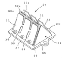
- the EGR device reed valve 24 includes a reed valve body 32, 32 that opens and closes a valve seat housing 31 having a triangular cross section connected to the EGR pipe 21, and a reed valve thereof.
- the stoppers 33, 33 that hold the open positions of the bodies 32, 32 are stacked and fixed with bolts 34, 34.
- the valve seat housing 31 is manufactured by die-casting an aluminum alloy, and the reed valve bodies 32 and 32 are made of a heat-resistant and springy SUS material (manufactured by Hitachi Metals, GIN6).
- the valve seat housing 31 is formed by providing a valve seat plate 36 on both sides of an opposing triangular plate 35 and providing a flange 37 connected to the EGR pipe 21 around the triangular plate 35 and the valve seat plate 36. Is done.
- Three valve seats 38 are formed on the valve seat plates 36 on both sides.
- the reed valve body 32 is formed by integrally connecting three lead portions 32a at the base so as to close these valve seats 38 (FIG. 1A).
- the stopper 33 is formed so that the tip end portion 33a is separated from the valve seat plate 36 so as to restrict the opening position when the three lead portions 32a are opened, and the intake air pressure in the direction of closing the lead portion 32a.
- An oval hole 39 is formed to act.
- the EGR device reed valve 24 is provided in the EGR pipe 21 so that the tip of the valve seat housing 31 protrudes from the intake manifold 11, and when the exhaust pressure is higher than the intake pressure, that is, the engine 10.
- the lead portion 32a of the reed valve body 32 is opened at the time of explosion, so that the exhaust gas flows to the intake manifold 11 side through the valve seat 38, and if the intake pressure becomes high, each lead portion 32a of the reed valve body 32. Closes the valve seat 38.
- the lead valve 24 for an EGR device in which a coating 25 having corrosion resistance and wear resistance is formed on the front and back surfaces of the reed valve body 32 and the front and back surfaces of the valve seat housing 31, and the manufacture thereof. Is the method.
- the component of this film 25 is (A) Polyamideimide resin 65 to 75 parts by mass (B) Fluororesin powder 10 to 20 parts by mass (C) Inorganic powder 10 to 30 parts by mass
- (A) As the polyamideimide resin a resin having heat resistance of 260 ° C. or higher and having a number average molecular weight of 2000 to 8000 before drying or baking is used.
- FEP a fluororesin in which tetrafluoroethylene and hexafluoropropylene are jointly combined
- one having an average particle diameter of 1 to 2 ⁇ m is used.
- (C) Inorganic powder having an average particle diameter of 1 to 2 ⁇ m is used, and it is preferable to add 5 to 15 parts by mass of SiO 2 and Al 2 O 3 as components, but SiO 2 and Al 2 O 3 may be used alone, or in addition to SiO 2 and Al 2 O 3 , graphite or molybdenum disulfide may be used.
- a solvent N-methyl-2-pyrrolidone (NMP)
- NMP N-methyl-2-pyrrolidone
- the lead valve body 32 and the valve seat housing 31 are sandblasted with alumina particles (# 220 mesh) before coating with a film-forming resin precursor, and the surface roughness Ra is about 1 to 1.5 ⁇ m. Keep the surface rough.
- a coating film is formed on the roughened reed valve body 32 and the valve seat housing 31 by spray coating or the like, and then heated and dried at 70 to 90 ° C. for 20 minutes or more. This spray coating and drying are repeated 3 to 5 times, and finally a coating film having a thickness of 30 ⁇ 10 ⁇ m, preferably 30 ⁇ m is formed, and then the coating film is baked by baking at 230 ° C. ⁇ 10 ° C. for 45 ⁇ 5 minutes. The film 25 is formed by this.
- the coating 25 is formed on the valve seat housing 31 over the entire surface of the valve seat housing 31, but is formed on the surface in contact with the exhaust gas, that is, the inner surface of the triangular plate 35 and the inner and outer surfaces of the valve seat plate 36. Also good.
- the characteristic of this film 25 is a coefficient of friction of 0.08 to 0.1 (measured with a reciprocating friction tester).
- Pencil hardness 5H JIS K 5400
- Cross-cut test 100/100 JIS K 5400
- Bending test passed 3mm JIS K 5400
- Corrosion resistance 500 hours or more JIS Z 2371 5% salt spray
- Solvent resistance Passed (Bend after 24 hours of toluene immersion)
- the maximum operating temperature was about 250 ° C.
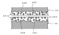
- FIG. 2 shows an enlarged schematic view of the cross section of the coating 25 formed on the reed valve body 32 and the valve seat housing 31, and the coating 25 in a state where the fluororesin powder 26B and the inorganic powder 26C are dispersed in the polyamideimide resin 26A. It becomes.
- the inorganic powder 26C By including the inorganic powder 26C in the coating 25 as described above, even if the reed valve body 32 frequently collides with the valve seat surface of the valve seat housing 31, the inorganic powder 26C has higher hardness than the polyamideimide resin 26A.
- the fluororesin powder 26B exhibits excellent resistance to sliding friction because it exhibits lubricity against contact friction between them.
- the surface of the reed valve body 32 and the valve seat housing 31 is based on a polyamide-imide resin, which is superior in heat resistance to the conventional fluororesin, and the coating is made by dispersing the fluororesin powder and the inorganic powder in this.
- No. 25 can have both heat resistance, impact resistance, impact relaxation at the time of sitting, and lubricity, and the durability against the seating impact can achieve a strength of about 1000 times.
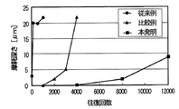
- FIG. 3 shows the resistance of the present invention in which both the reed valve body and the valve seat housing are coated, a comparative example in which a film is coated on one of the reed valve body and the valve seat housing, and a conventional example in which the film is coated with a fluororesin. The result of an abrasion evaluation test is shown.
- Abrasion resistance evaluation test is performed at room temperature and in an air atmosphere with a load of 1 kgf on the test piece and reciprocating sliding with a stroke of 10 mm (reciprocating speed: 9 cpm up to 10 reciprocations, 240 cpm after 10 reciprocations) and the test. The wear depth of the piece was measured.
- the wear depth was 20 ⁇ m after about 100 times, and in the comparative example, a certain degree of wear resistance was exhibited, but at 4000 times, the wear depth was 20 ⁇ m.
- the wear depth was 10 ⁇ m even after 12,000 times, and it was confirmed that the wear resistance was improved 120 times compared to the conventional example.
- FIG. 4 shows the results of evaluation of wear resistance against the combustion product (soot).
- the test piece was dropped at room temperature with a deteriorated oil simulating soot and a load of 1 kgf was applied as in FIG. This is a measurement of the number of reciprocations and the wear depth of the test piece when sliding back and forth with a stroke of 10 mm.
- the wear depth was 18 ⁇ m after about 200 times, but in the present invention, the wear depth was 3 ⁇ m even after 16000 times, and the wear resistance was 80 times or more against the wrinkles. It was confirmed.
- FIG. 5 shows the impact resistance (tapping) confirmation test result of the conventional example coated with fluororesin and the coating of the present invention.
- the strike test was performed by measuring the number of strikes and the wear depth when an aluminum ball (A1050) was hit on a test piece at a crank rotation speed of 300 rpm, and the test atmosphere temperature was 350 ° C. and 200 ° C. in the atmosphere. It was.
- the conventional example 1 (350 ° C.) has a wear depth of 35 ⁇ m after 100 times
- the conventional example 2 (200 ° C.) has a wear depth of 30 ⁇ m after 100 times
- the present invention 1 (350 ° C.) In Invention 2 (200 ° C.)
- the wear depth was 5 ⁇ m even at 100,000 times, and it was confirmed that the impact resistance (striking) property was improved 1000 times or more than the conventional example.
- the valve seat housing is made of SUS, is based on an aluminum alloy, and can be beaten at a low cost with almost no increase in weight.
Landscapes
- Engineering & Computer Science (AREA)
- General Engineering & Computer Science (AREA)
- Mechanical Engineering (AREA)
- Chemical & Material Sciences (AREA)
- Combustion & Propulsion (AREA)
- Check Valves (AREA)
- Exhaust-Gas Circulating Devices (AREA)
Abstract
200℃を超える高温下で、排ガス中に高濃度の硫黄酸化物が含まれていても腐食や破損のないEGR装置用リードバルブ及びその製造方法を提供する。 EGR管21に、弁座ハウジング31とその弁座ハウジング31を開閉するリード弁体32とからなるリードバルブ24を接続したEGR装置用リードバルブにおいて、弁座ハウジング31とリード弁体32に、ポリアミドイミド樹脂中に、フッ素樹脂粉末と無機粉末を分散させた皮膜を形成したものである。
Description
本発明は、エンジンのEGR装置に係り、特にEGR装置にリード式ワンウエイバルブを用いたEGR装置用リードバルブ及びその製造方法に関するものである。
エンジンの排ガス中のNOxを低減するために、エンジンに排気ガスを再循環するEGR(排気ガス再循環)装置が広く使用されている。
このEGR環装置においては、排ガスを吸気側に再循環するため、吸気側平均圧力が、排気側平均圧力より高いエンジン(高過給エンジンなど)では、排気ガス再循環(EGR)が作動できない。
このような場合でも、エンジンの爆発時には、短時間ではあるものの、吸気側より排気圧力が高い部分があるため、リード式ワンウエイバルブを使用することで、EGRを作動させることが知られている(特許文献1,2)。
このリード式ワンウエイバルブは、特許文献1,2に示されるように、アルミ合金からなる断面三角形状の弁座ハウジングに、その弁座を開閉するリード弁体とそのリード弁体の開放位置を保持するストッパーを重ねてボルトで固定して構成され、エンジンの爆発直後に排気された排ガス圧で、リード弁体を開いて吸気側に再循環できるようにしている。
しかしながら、現在使用されているバルブが破損するおそれがあり、その破壊原因として次のようなものが考えられる。
先ず、リードバルブのリード弁体は、頻繁に開閉を繰り返し、その度に弁座をリード弁体のバネ力と吸気圧で弁座に衝突して叩かれると共に摺動摩擦も生じる。リード弁体はSUS製で、弁座ハウジングはアルミニウム製であるため、リード弁体の衝突で弁座面に欠損が生じたりリード弁体が破損しやすくなる。
またリードバルブを、低質燃料(高硫黄燃料)を用いた際に排出される排ガスがEGRガスとして流れる環境で使用した場合、リード弁体及びアルミニウム合金からなる弁座が、燃焼中に生成される硫黄酸化物を含む排ガスと排ガス中の水分が反応して発生する硫酸分と主に反応する酸により腐食される。
さらにHSG(ハウジング)側に腐食によりできた欠損部分がバルブ作動時にリードに高い応力集中を発生させるため早期に先端割れを発生させ製品寿命を著しく低下させる。
不具合の対応としてリードバルブ表面にフッ素樹脂をコーティングする技術が開発され実用に供されているが、実用耐熱温度が約200℃程度であり、排ガスの冷却装置(EGRクーラ)の経年劣化等によりリードバルブ入口温度が上昇した場合には耐力不足で、リードバルブが破損することが知られている。
また、同部位の耐衝撃力アップとして、ゴムコートが知られているが、耐熱温度が180℃であり、200℃を超える温度では採用できない。
また弁座ハウジングの材質を、アルミニウムから腐食耐力のあるSUS系金属を採用することも考えられるが、大幅なコストアップおよび重量増加が避けられない。
そこで、本発明の目的は、上記課題を解決し、200℃を超える高温下で、排ガス中に高濃度の硫黄酸化物が含まれていても腐食や破損のないEGR装置用リードバルブ及びその製造方法を提供することにある。
上記目的を達成するために請求項1の発明は、EGR管に、弁座ハウジングとその弁座ハウジングを開閉するリード弁体とからなるリードバルブを接続したEGR装置用リードバルブにおいて、弁座ハウジングとリード弁体に、ポリアミドイミド樹脂中に、フッ素樹脂粉末と無機粉末を分散させた皮膜を形成したことを特徴とするEGR装置用リードバルブである。
請求項2の発明は、弁座ハウジングとその弁座ハウジングを開閉するリード弁体とからなるEGR装置用リードバルブの製造方法において、ポリアミドイミド樹脂を65~75質量部、フッ素樹脂粉末を10~20質量部、無機粉末を10~30質量部とし、これに溶剤を加えて弁座ハウジングとリード弁体に塗布した後乾燥させ、これを数回繰り返し、皮膜厚さを30±10μmにした後、これを焼成して皮膜を形成したことを特徴とするEGR装置用リードバルブの製造方法である。
請求項3の発明は、弁座ハウジングとリード弁体の表面をサンドブラストにより粗面化した後、皮膜を形成する請求項2記載のEGR装置用リードバルブの製造方法である。
請求項4の発明は、フッ素樹脂粉末と無機粉末の平均粒径が1~2μmである請求項3記載のEGR装置用リードバルブの製造方法である。
請求項5の発明は、フッ素樹脂粉末がFEPであり、無機粉末として、SiO2とAl2O3の双方をそれぞれ5~15質量部を用いる請求項2記載のEGR装置用リードバルブの製造方法である。
本発明は、弁座ハウジングとリード弁体に、ポリアミドイミド樹脂中に、フッ素樹脂粉末と無機粉末を分散させた皮膜を形成することで、耐腐食性、耐摩耗性、耐衝撃性を向上できるという優れた効果を発揮する。
以下、本発明の好適な一実施の形態を添付図面に基づいて詳述する。
先ず図8により、本発明のEGR装置用リードバルブが適用される過給機付きディーゼルエンジンの吸排気装置とEGR装置を説明する。
図8において、ディーゼルエンジン10の吸気マニホールド11と排気マニホールド12は、過給機13のコンプレッサ14とタービン15にそれぞれ連結される。エアクリーナ17より上流側吸気管16aに吸引された空気は、コンプレッサ14で昇圧され、下流側吸気管16bのインタークーラ18を通って冷却され、吸気スロットルバルブ19を介して吸気マニホールド11からディーゼルエンジン10に供給される。ディーゼルエンジン10からの排気ガスは、排気マニホールド12に排出され、タービン15を駆動した後、排気ブレーキ装置23を介して排気管20に排気される。
排気マニホールド12と下流側吸気管16bには排気ガスの一部をエンジン10の吸気系である吸気マニホールド11側に戻してNOxを低減するためのEGR管21が接続され、そのEGR管21に、排ガスをエンジン冷却水で冷却するEGRクーラ22が接続される、EGRクーラ22の下流側には、EGRバルブ23と、本発明のEGR装置用リードバルブ24が接続される。
EGR装置用リードバルブ24は、図6、図7に示すように、EGR管21に接続する断面三角形状の弁座ハウジング31に、その弁座を開閉するリード弁体32,32とそのリード弁体32,32の開放位置を保持するストッパー33,33を重ねてボルト34,34で固定して構成される。この弁座ハウジング31は、アルミニウム合金のダイキャスト鋳造で製造され、リード弁体32,32は、耐熱性がありバネ性のあるSUS材(日立金属製、GIN6)などで形成される。
弁座ハウジング31は、対向した三角形状板35の両側に弁座板36が設けられ、その三角形状板35と弁座板36の周囲に、EGR管21に接続するフランジ37が設けられて形成される。両側の弁座板36には、それぞれ3つの弁座38(図7、図1(b))が形成される。
リード弁体32は、これら弁座38を閉じるように3枚のリード部32aが基部で一体に連結されて形成される(図1(a))。ストッパー33は、3枚のリード部32aが開いたときの開放位置を規制するように、その先端部33aが弁座板36から離れるように形成されると共に、リード部32aを閉じる方向に吸気圧力を作用させるための長円状の穴39が形成される。
このEGR装置用リードバルブ24は、図7に示すように弁座ハウジング31の先端が吸気マニホールド11に凸となるようにEGR管21に設けられ、吸気圧より排気圧が高いとき、すなわちエンジン10の爆発時にリード弁体32のリード部32aが開いて、弁座38を通して、排気ガスが吸気マニホールド11側に流すように、また、吸気圧力が高くなれば、リード弁体32の各リード部32aが弁座38を閉じるようになっている。
さて、本発明は、図1に示すように、リード弁体32の表裏面及び弁座ハウジング31の表裏面に耐食性及び耐摩耗性を有する皮膜25を形成したEGR装置用リードバルブ24及びその製造方法である。
この皮膜25の成分は、
(A)ポリアミドイミド樹脂 65~75質量部
(B)フッ素樹脂粉末 10~20質量部
(C)無機粉末 10~30質量部
からなる。
(A)ポリアミドイミド樹脂 65~75質量部
(B)フッ素樹脂粉末 10~20質量部
(C)無機粉末 10~30質量部
からなる。
(A)ポリアミドイミド樹脂としては、耐熱温度260℃以上の耐熱性があるもので、乾燥ないし焼成前の数平均分子量が、2000~8000であるものを用いる。
(B)フッ素樹脂粉末としては、特にFEP(テトラフルオロエチレンとヘキサフルオロプロピレンの共同合体したフッ素樹脂)を用いるのが好ましく、平均粒径は1~2μmのものを用いる。
(C)無機粉末としては、平均粒径が1~2μmのものを用い、成分としてはSiO2とAl2O3をそれぞれ5~15質量部添加するのが好ましいが、SiO2とAl2O3を単独で使用してもよい、またSiO2とAl2O3を他に、グラファイトや2硫化モリブデンなどを用いてもよい。
この(A)~(C)の成分に溶剤(N-メチル-2-ピロリドン(NMP))を加えて皮膜形成樹脂前駆体とする。
他方、リード弁体32と弁座ハウジング31は、皮膜形成樹脂前駆体をコーティングする前に、アルミナ粒子(#220メッシュ)でサンドブラスト処理を行い、その表面荒さをRaで1~1.5μm程度に粗面化しておく。
この粗面化したリード弁体32と弁座ハウジング31に皮膜形成樹脂前駆体をスプレー塗装等にてコーティング膜を形成した後、70~90℃で20分以上加熱乾燥する。このスプレー塗装と乾燥を3~5回繰り返し、最終的に30±10μm、好ましくは30μm厚さのコーティング膜を形成した後、230℃±10℃で45±5分焼き付けてコーティング膜を焼成することで皮膜25を形成する。
弁座ハウジング31への皮膜25の形成は、弁座ハウジング31の全面に形成するが、排ガスと接触する面すなわち、三角形状板35の内面と弁座板36の内外面に形成するようにしてもよい。
この皮膜25の特性は
摩擦係数 0.08~0.1(往復摩擦試験機で測定)
鉛筆硬度 5H(JIS K 5400)
碁盤目テスト 100/100(JIS K 5400)
折り曲げテスト 合格 3mm(JIS K 5400)
耐食性 500時間以上(JIS Z 2371 5%塩水噴霧)
耐溶剤性 合格 (トルエン24時間浸漬後、折曲げ)
最高使用温度 250℃程度
であった。
摩擦係数 0.08~0.1(往復摩擦試験機で測定)
鉛筆硬度 5H(JIS K 5400)
碁盤目テスト 100/100(JIS K 5400)
折り曲げテスト 合格 3mm(JIS K 5400)
耐食性 500時間以上(JIS Z 2371 5%塩水噴霧)
耐溶剤性 合格 (トルエン24時間浸漬後、折曲げ)
最高使用温度 250℃程度
であった。
図2は、リード弁体32と弁座ハウジング31に形成した皮膜25の断面を拡大した模式図を示し、ポリアミドイミド樹脂26A中に、フッ素樹脂粉末26Bと無機粉末26Cが分散した状態の皮膜25となる。
このように皮膜25中に無機粉末26Cを含むことで、リード弁体32が弁座ハウジング31の弁座面に頻繁に衝突しても、無機粉末26Cは、ポリアミドイミド樹脂26Aより硬度が高いため、耐衝撃性を発揮し、またフッ素樹脂粉末26Bは、両者の接触摩擦に対して潤滑性があるため、耐摺動摩擦性に優れたものとなる。
このように、リード弁体32と弁座ハウジング31の面に従来のフッ素樹脂より耐熱性に優れた、ポリアミドイミド系樹脂をベースとし、これにフッ素樹脂粉末と無機粉末を分散させることで、皮膜25は耐熱性、耐衝撃性、着座時の衝撃緩和、潤滑性を併せ持つことが可能となり、着座衝撃に対する耐久性でおよそ1000倍の耐力を実現することができる。
次に、本発明の皮膜の試験結果を図3~図5により説明する。
図3は、リード弁体と弁座ハウジングの双方に皮膜を施した本発明と、リード弁体又は弁座ハウジングの片方に皮膜を施した比較例と、皮膜をフッ素樹脂コートした従来例の耐摩耗性評価試験の結果を示したものである。
耐摩耗性評価試験は、室温、大気雰囲気中で、試験片に荷重1kgfをかけ、10mmのストロークで往復摺動(往復速度;10往復まで9cpm、10往復以降240cpm)したときの往復回数と試験片の摩耗深さを測定したものである。
図3より従来例では、100回程度で、摩耗深さが20μmとなり、比較例では、ある程度の耐摩耗性を発揮したが4000回で、摩耗深さが20μmとなった。
これに対して、本発明では12000回でも摩耗深さが10μmであり、耐摩耗性が従来例より120倍向上していることが確認された。
図4は、燃焼生成物(煤)に対する耐摩耗性評価結果を示したもので、試験片に室温下で、煤を模擬して劣化オイルを滴下し、図3と同様に、荷重1kgfをかけ、10mmのストロークで往復摺動したときの往復回数と試験片の摩耗深さを測定したものである。
図4より、従来例では、200回程度で、摩耗深さが18μmとなったが、本発明では16000回でも摩耗深さが3μmであり、煤に対して80倍以上の耐摩耗性を有することが確認された。
図5は、フッ素樹脂コートした従来例と本発明の皮膜の耐衝撃(叩かれ)性確認試験結果を示したものである。
叩き試験は、試験片にアルミ球(A1050)を、クランク回転数300rpmで叩いたときの叩き回数と摩耗深さを測定したもので、試験雰囲気温度を、大気中で350℃と200℃で行った。
この結果、従来例1(350℃)は100回で摩耗深さが35μm、従来例2(200℃)は、100回で摩耗深さが30μmとなるのに対し、本発明1(350℃)及び本発明2(200℃)では、共に100000回でも摩耗深さが5μmであり、耐衝撃(叩かれ)性は、従来例より1000倍以上に向上することが確認できた。
また、耐食性について、リード弁体の人工排気結露水を用いた試験を行った結果、フッ素系樹脂では、皮膜の部分的な剥離が見られた。これに対して本発明の皮膜では、変色は見られただけで皮膜の浮き上がり等は発生しないことが確認できた。
さらに耐腐食性については、ベースのアルミダイキャストの素地のままのものに対して、本発明の皮膜を形成したものでは、同一試験時間で全く母材への腐食は発生していないことが確認できた。
以上より、本発明は、弁座ハウジングをSUS製にすることなく、アルミニウム合金をベースとし、ほとんど重量増加することなく、低コストで、叩かれ寿命の大幅な増加が可能となる。
また高硫黄燃料使用時の耐力も大幅に向上することが可能となったため、通常50ppm程度が実用限界であるものを、2000ppm以上の高濃度燃料の使用時にも実用性を確保することが可能となった。
従って、本発明により、250~350℃程度までのEGRガス温度での使用にも耐えることが可能となり、ロバストネスの高いバルブの提供が可能となる。
21 EGR管
24 EGR装置用リードバルブ
25 皮膜
31 弁座ハウジング
32 リード弁体
24 EGR装置用リードバルブ
25 皮膜
31 弁座ハウジング
32 リード弁体
Claims (5)
- EGR管に、弁座ハウジングとその弁座ハウジングを開閉するリード弁体とからなるリードバルブを接続したEGR装置用リードバルブにおいて、弁座ハウジングとリード弁体に、ポリアミドイミド樹脂中に、フッ素樹脂粉末と無機粉末を分散させた皮膜を形成したことを特徴とするEGR装置用リードバルブ。
- 弁座ハウジングとその弁座ハウジングを開閉するリード弁体とからなるEGR装置用リードバルブの製造方法において、ポリアミドイミド樹脂を65~75質量部、フッ素樹脂粉末を10~20質量部、無機粉末を10~30質量部とし、これに溶剤を加えて弁座ハウジングとリード弁体に塗布した後乾燥させ、これを数回繰り返し、皮膜厚さを30±10μmにした後、これを焼成して皮膜を形成したことを特徴とするEGR装置用リードバルブの製造方法。
- 弁座ハウジングとリード弁体の表面をサンドブラストにより粗面化した後、皮膜を形成する請求項2記載のEGR装置用リードバルブの製造方法。
- フッ素樹脂粉末と無機粉末の平均粒径が1~2μmである請求項3記載のEGR装置用リードバルブの製造方法。
- フッ素樹脂粉末がFEPであり、無機粉末として、SiO2とAl2O3の双方をそれぞれ5~15質量部を用いる請求項2記載のEGR装置用リードバルブの製造方法。
Applications Claiming Priority (2)
| Application Number | Priority Date | Filing Date | Title |
|---|---|---|---|
| JP2011010237A JP2012149610A (ja) | 2011-01-20 | 2011-01-20 | Egr装置用リードバルブ及びその製造方法 |
| JP2011-010237 | 2011-01-20 |
Publications (1)
| Publication Number | Publication Date |
|---|---|
| WO2012099050A1 true WO2012099050A1 (ja) | 2012-07-26 |
Family
ID=46515676
Family Applications (1)
| Application Number | Title | Priority Date | Filing Date |
|---|---|---|---|
| PCT/JP2012/050702 Ceased WO2012099050A1 (ja) | 2011-01-20 | 2012-01-16 | Egr装置用リードバルブ及びその製造方法 |
Country Status (2)
| Country | Link |
|---|---|
| JP (1) | JP2012149610A (ja) |
| WO (1) | WO2012099050A1 (ja) |
Citations (3)
| Publication number | Priority date | Publication date | Assignee | Title |
|---|---|---|---|---|
| JP2001132557A (ja) * | 1999-10-29 | 2001-05-15 | Isuzu Motors Ltd | リード弁を備えたegr装置 |
| JP2004168916A (ja) * | 2002-11-21 | 2004-06-17 | Toshiba Corp | 熱硬化型塗料、その塗装方法及びその塗装物 |
| JP2008002387A (ja) * | 2006-06-23 | 2008-01-10 | Toshiba Kyaria Kk | 冷媒圧縮機及びこれを用いた冷凍サイクル装置 |
Family Cites Families (2)
| Publication number | Priority date | Publication date | Assignee | Title |
|---|---|---|---|---|
| JP2000249004A (ja) * | 1999-03-02 | 2000-09-12 | Isuzu Motors Ltd | リード弁を備えたegr装置 |
| JP2002053883A (ja) * | 2000-08-07 | 2002-02-19 | Toyota Motor Corp | 摺動部材用組成物 |
-
2011
- 2011-01-20 JP JP2011010237A patent/JP2012149610A/ja active Pending
-
2012
- 2012-01-16 WO PCT/JP2012/050702 patent/WO2012099050A1/ja not_active Ceased
Patent Citations (3)
| Publication number | Priority date | Publication date | Assignee | Title |
|---|---|---|---|---|
| JP2001132557A (ja) * | 1999-10-29 | 2001-05-15 | Isuzu Motors Ltd | リード弁を備えたegr装置 |
| JP2004168916A (ja) * | 2002-11-21 | 2004-06-17 | Toshiba Corp | 熱硬化型塗料、その塗装方法及びその塗装物 |
| JP2008002387A (ja) * | 2006-06-23 | 2008-01-10 | Toshiba Kyaria Kk | 冷媒圧縮機及びこれを用いた冷凍サイクル装置 |
Also Published As
| Publication number | Publication date |
|---|---|
| JP2012149610A (ja) | 2012-08-09 |
Similar Documents
| Publication | Publication Date | Title |
|---|---|---|
| US9822728B2 (en) | Engine and piston | |
| US10487773B2 (en) | Vehicle mechanical component and piston | |
| JP5304949B2 (ja) | ターボチャージャ | |
| Tamura et al. | Multilayered thermal barrier coating for land-based gas turbines | |
| JP6295008B2 (ja) | 回転機械の羽根車、コンプレッサ、過給機及び回転機械の羽根車の製造方法 | |
| JP6386162B2 (ja) | 回転機械の羽根車、コンプレッサ、過給機及び回転機械の羽根車の製造方法 | |
| WO2006126993A1 (en) | Turbocharger compressor having improved erosion-corrosion resistance | |
| CN108798878A (zh) | 防震颤装置和包括该防震颤装置的涡轮增压器废气门组件 | |
| WO2013115358A1 (ja) | インタークーラー | |
| US20170314516A1 (en) | Engine system for exhausting condensate water | |
| JP2013002302A (ja) | 内燃機関の排気装置 | |
| CN1816647A (zh) | 具有覆层的金属构件 | |
| WO2012099050A1 (ja) | Egr装置用リードバルブ及びその製造方法 | |
| CN101553658A (zh) | 废气再循环阀 | |
| JP5644534B2 (ja) | 可変容量ターボチャージャ及びその製造方法 | |
| WO2010019664A3 (en) | Combined high temperature exhaust gas and charge air cooler with protective internal coating | |
| CN207333057U (zh) | 集成式文丘里管 | |
| JP6486978B2 (ja) | 積層部材、並びに、これを用いた羽根車、圧縮機及びエンジン | |
| KR20200028286A (ko) | 배기가스 재순환 장치용 유량 제어 밸브 | |
| CN201083134Y (zh) | 三缸汽油机的对称型进排气凸轮 | |
| JP5280113B2 (ja) | 多気筒内燃機関における排気ガス還流装置 | |
| JP5699512B2 (ja) | リードバルブ | |
| JP2006291954A (ja) | 排気ガスによって掃気される構成部品、特にエンジンセットの構成部品、およびそのような構成部品をコーティングする方法 | |
| TW202010830A (zh) | 以新式燃料組成作為一改良式柴油引擎之燃料的方法 | |
| JP2005090833A (ja) | 熱交換器 |
Legal Events
| Date | Code | Title | Description |
|---|---|---|---|
| 121 | Ep: the epo has been informed by wipo that ep was designated in this application |
Ref document number: 12737163 Country of ref document: EP Kind code of ref document: A1 |
|
| NENP | Non-entry into the national phase |
Ref country code: DE |
|
| 122 | Ep: pct application non-entry in european phase |
Ref document number: 12737163 Country of ref document: EP Kind code of ref document: A1 |