WO2012098845A1 - 画像符号化方法、画像符号化装置、画像復号方法及び画像復号装置 - Google Patents
画像符号化方法、画像符号化装置、画像復号方法及び画像復号装置 Download PDFInfo
- Publication number
- WO2012098845A1 WO2012098845A1 PCT/JP2012/000193 JP2012000193W WO2012098845A1 WO 2012098845 A1 WO2012098845 A1 WO 2012098845A1 JP 2012000193 W JP2012000193 W JP 2012000193W WO 2012098845 A1 WO2012098845 A1 WO 2012098845A1
- Authority
- WO
- WIPO (PCT)
- Prior art keywords
- block
- candidate
- motion vector
- image
- encoding
- Prior art date
Links
Images


Classifications
-
- H—ELECTRICITY
- H04—ELECTRIC COMMUNICATION TECHNIQUE
- H04N—PICTORIAL COMMUNICATION, e.g. TELEVISION
- H04N19/00—Methods or arrangements for coding, decoding, compressing or decompressing digital video signals
- H04N19/50—Methods or arrangements for coding, decoding, compressing or decompressing digital video signals using predictive coding
- H04N19/503—Methods or arrangements for coding, decoding, compressing or decompressing digital video signals using predictive coding involving temporal prediction
- H04N19/51—Motion estimation or motion compensation
- H04N19/513—Processing of motion vectors
- H04N19/517—Processing of motion vectors by encoding
- H04N19/52—Processing of motion vectors by encoding by predictive encoding
-
- H—ELECTRICITY
- H04—ELECTRIC COMMUNICATION TECHNIQUE
- H04N—PICTORIAL COMMUNICATION, e.g. TELEVISION
- H04N19/00—Methods or arrangements for coding, decoding, compressing or decompressing digital video signals
- H04N19/46—Embedding additional information in the video signal during the compression process
-
- H—ELECTRICITY
- H04—ELECTRIC COMMUNICATION TECHNIQUE
- H04N—PICTORIAL COMMUNICATION, e.g. TELEVISION
- H04N19/00—Methods or arrangements for coding, decoding, compressing or decompressing digital video signals
- H04N19/50—Methods or arrangements for coding, decoding, compressing or decompressing digital video signals using predictive coding
- H04N19/503—Methods or arrangements for coding, decoding, compressing or decompressing digital video signals using predictive coding involving temporal prediction
- H04N19/51—Motion estimation or motion compensation
- H04N19/56—Motion estimation with initialisation of the vector search, e.g. estimating a good candidate to initiate a search
Definitions
- the present invention relates to an image encoding method for encoding an image, an image encoding device, an image decoding method for decoding encoded image data, and an image decoding device.
- the H.264 / AVC (Advanced Video Coding) standard has been established as a method for recording and transmitting image and audio information as digital data.
- ISO / IEC MPEG and ITU-T VCEG have established JCT-VC (Joint Collaborative Team On Video Coding) to realize a compression ratio exceeding this, and are considering the next generation method called HEVC (High Efficiency Video Coding). I'm starting.
- the prediction vector is obtained by performing a median operation on the X-direction component and the Y-direction component from the motion vectors of the encoded macroblocks above, left, and upper right of the encoding target macroblock. It was.
- the motion vectors at the same position as the encoding target macroblocks of the top, left, and nearest reference frames are compared, and the one closest to the encoding target macroblock motion vector is selected as the prediction vector. Transmitted as a flag.
- the motion vector competition method transmits a flag, if the result of the median operation is the same as the prediction vector, the amount of code increases by the amount of the flag.
- the processing when it is outside the frame region and the flag description method are not efficient, and the flag is recorded by selecting two from three candidates.
- candidate blocks in a narrow range can be selected, there is a problem that the prediction error is large, the code amount is large, and the coding efficiency is low.
- the present invention has been made in view of the above problems, and an object of the present invention is to provide an image encoding technique and an image decoding technique capable of realizing high encoding efficiency by appropriate motion prediction.
- the present application includes various means for solving the above-mentioned problems, and one of them is as follows.
- An image encoding device that encodes an input image, a motion search unit that performs a motion search using an encoding target block obtained by dividing the input image and a reference image, and a motion vector of the encoding target block,
- An adaptive PMV selector that generates a motion vector predictor from motion vectors of candidate blocks consisting of some or all of the blocks around the current block, and a difference vector is calculated from the motion vector of the current block and the motion vector predictor.
- encoding efficiency can be improved.
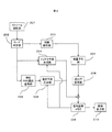
- FIG. 1 is a block diagram of an image encoding device according to Embodiment 1.
- FIG. It is a block diagram of the image decoding apparatus which concerns on Example 2. It is explanatory drawing of the candidate block which selects a motion vector as PMV (predictive motion vector) which concerns on Example 1.
- FIG. It is explanatory drawing about the outline
- FIG. FIG. 3 is an image encoding flowchart used in the image encoding apparatus according to the first embodiment. It is a flowchart of the image decoding method which concerns on Example 2.
- 10 is an explanatory diagram of a data recording medium according to Embodiment 3.
- FIG. It is a figure which shows the PMV selection determination flow per frame in the adaptive PMV selection part which concerns on Example 1.
- FIG. 1 It is a figure which shows the PMV selection determination flow per block in the adaptive PMV selection part which concerns on Example 1.
- FIG. It is a figure which shows the adjustment flow of the candidate block which performs PMV selection per block in the adaptive PMV selection part which concerns on Example 1.
- FIG. It is a figure which shows the example of the description method as a flag of the vector selected concerning Example 1.
- motion vector competition in each description and each drawing of this specification indicates a conventional encoding method
- adaptive motion vector selection indicates a new encoding method according to the present invention.
- PMV selection means to select one of motion vectors of candidate blocks and generate a predicted motion vector (Predicted Motion Vector: PMV) from the selected motion vector (selecting median or the like as it is) And new generation by combining a plurality of motion vectors, etc.).
- 0 vec or “0 vector” in each description and each drawing of the present specification indicates that the value of each component is a vector of 0, or conversion to such a vector and setting.
- non-referenceable in each description and each drawing of this specification indicates that block information cannot be acquired.
- the position of the candidate block is outside the range of the screen.
- can be referred to means that block information can be acquired.
- each description of the present specification and “block information” in each drawing include a vector and a reference frame number.
- coding mode in each description and each drawing of the present specification includes a combination of the type of intra prediction / inter prediction and the block size to be applied.
- FIG. 1 shows a block diagram of an image coding apparatus according to the first embodiment.
- the image coding apparatus includes a block division unit 101, a prediction error calculation unit 102, an intra prediction unit 104, a PMV prediction coding unit 107, an adaptive PMV selection unit 106, a motion search unit 105, a decoded image memory 103, a DCT conversion unit 108, A quantization unit 109, an entropy encoding unit 110, an inverse quantization unit 111, an inverse DCT conversion unit 112, a mode selection unit 113, and a data output unit 114 are provided.
- each component of the image encoding device may be an autonomous operation of each component as described below, for example.
- the computer control unit may be realized in cooperation with software stored in the computer storage unit.
- the block dividing unit 101 inputs an original image to be encoded, and divides it into blocks that are encoding units.
- CU Coding Unit
- PU Prediction Unit
- the prediction error calculation unit 102 calculates the difference component between the generated prediction image and the original image and outputs it.
- prediction methods there are generally intra (intra-frame) prediction and inter (inter-frame) prediction.
- Intra prediction is performed by the intra prediction unit 104
- inter prediction is performed by the inter prediction unit 120 including the PMV prediction encoding unit 107, the adaptive PMV selection unit 106, and the motion search unit 105.
- Intra prediction uses the information of the same frame encoded before the encoding target block
- inter prediction uses the information of the previous or subsequent frame encoded before the encoding target frame as the reproduction time. Use. These are stored in the decoded image memory 103.
- intra prediction unit 104 motion prediction unit
- decoded image memory 103 decoded image memory
- the intra prediction unit 104 predicts the pixels of the encoding target block using information of the same frame encoded before the encoding target block.
- an intra prediction method an existing method may be used.
- the motion search unit 105 searches for a motion vector (Motion Vector: MV) using the reference frame and the encoding target block stored in the decoded image memory 103.
- MV Motion Vector
- the accuracy of the pixels may be an integer or a decimal, and 1/4 pixel accuracy is preferable by interpolation of the reference frame by a filter, but 1/2 or 1/8 may be used.
- an existing method is used for the motion search method.
- the adaptive PMV selection unit 106 uses the surrounding block in the same frame of the encoding target block and the same position of the reference frame and the information of the surrounding block to adaptively determine the PMV by temporal and spatial discrimination. Select In this embodiment, the PMV is adaptively discriminated with both temporal discrimination and spatial discrimination, but only one of them may be used. Details of the method, the candidate surrounding blocks, and the PMV selection method will be described later.
- a block (Co-located Block) (S) at the same position as the current block to be encoded is taken as a candidate, arranged in order as A, B, S, and if there is the same vector among these, it is excluded from the candidate
- the one closest to the vector of the encoding target block is selected and indicated by a flag.
- a backward reference frame may be used as long as it is an encoded frame. Further, not only one frame but also a plurality of encoded frames may be referred to.
- the adaptive motion vector selection method used in the adaptive PMV selection unit of the present embodiment not only the left side and the upper side of the block to be encoded, but also the upper right (C) and the upper left (D) are included in the candidates.
- blocks surrounding the block S of the reference frame can be included in the candidates. That is, (a) number, (b) spatial position (block in a frame) and (c) temporal position (block in another frame) of candidate blocks used by the adaptive PMV selection unit can be changed. Like that. Details of the selection method will be described later.
- the neighboring blocks are sequentially It is checked whether the block has a motion vector, and if it is available, it is a candidate for PMV selection. Specifically, if B1 cannot be referenced in 303, B2, B3, and B4 are sequentially checked. Similarly, when A1 cannot be referred to, A2, A3 and A4 are checked. When S1 cannot be referred to, S2, S3 and S4 are checked. Scanning may be performed in order from the top left of the encoding target frame. For block B, left to right, bottom to top, for block A, top to bottom, right to left, for block S, normal raster scan order, left to right, top to bottom It becomes the order of.
- the PMV predictive encoding unit 107 calculates the difference vector (Differential Motion Vector: DMV) by subtracting the PMV from the MV and encodes it. In addition, motion prediction is performed from the reference frame using MV to create a prediction block.
- DMV Difference Vector
- DCT conversion unit 108 DCT conversion is performed on the residual component input from the prediction error calculation unit 102 and converted into a coefficient. Then, it is sent to the quantization part 109 and each transform coefficient is quantized.
- the quantized coefficients are sent to the entropy coding unit 110, information compression using a variable length code or the like is performed according to a certain order, and the data is sent to the mode selection unit 113.
- the quantized coefficient is also sent to the inverse quantization unit 111, returned to the transform coefficient by inverse quantization, and further restored to the residual component by the inverse DCT transform unit 112.
- the residual component is added with information from the intra prediction unit 104 and the series of motion prediction units, returns to the decoded image, and is stored in the decoded image memory 103.
- the decoded image is input to the mode selection unit 113 and used for mode selection.
- the mode selection unit 113 selects a mode with the highest coding efficiency for the block based on information on a plurality of coding modes. For each coding mode, an error (coding error) between the original image and the decoded image and a code amount generated when the coding mode is used are calculated, and an appropriate coding mode is selected from the relationship between the two. For example, an existing method such as a Rate-Distortion optimization method may be used as a method for selecting an encoding mode with the highest encoding efficiency. This method is a method for calculating the coding error between the code amount and the original image after decoding for all modes for each macroblock, and selecting the best mode according to the cost calculation formula.
- the data output unit 114 outputs the selected code to create an encoded stream, and the image is encoded.
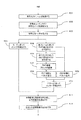
- step 501 is processing for inputting an original image to be encoded from the decoded image memory 103 and dividing it into blocks.
- the size of each block is variable.
- the aforementioned CU and PU may be used.
- Step 501 is executed by the block dividing unit 101.
- step 502 intra prediction is performed on the block of the original image acquired in step 501.
- An existing method may be used for intra prediction, and prediction is performed for a plurality of modes according to each intra prediction mode.
- the processing in step 502 is executed in the intra prediction unit 104.
- step 503 residual components are acquired for pixels of the intra-predicted coding block, and DCT transform processing, quantization processing, and entropy coding processing of the residual components are performed to calculate encoded data. . Furthermore, entropy decoding processing, inverse quantization, and inverse DCT conversion processing are performed on the encoded data to create a decoded image. As a result, the encoded data and the decoded image are output.
- the process of step 503 is performed in this order in the prediction error calculation unit 102, the DCT conversion unit 108, the quantization unit 109, and the entropy encoding unit 110.
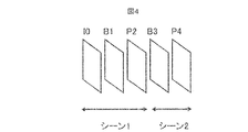
- step 504 scene analysis is performed.
- the outline of the scene analysis will be described with reference to FIG.
- GOP Group of Pictures: a group of frames related to prediction in the time direction.
- FIG. 4 shows a case where switching between scene 1 and scene 2 occurs between the P2 frame and the B3 frame.
- the P4 and B3 frames refer to the motion vector of the P2 frame, but an effective motion vector cannot be acquired because the scenes are different.
- a plurality of decoded images are analyzed to find a scene change without using a flag, or as a result of scene analysis on the encoder side, the detected scene change position is transmitted to the decoder by a flag,
- scene analysis processing may be performed in units of frames or in units of blocks. This process is not shown as a clear block, but is executed before the motion search by the motion search unit 105 in the inter prediction unit 120.
- step 505 motion search is performed for each inter prediction mode.
- Inter prediction modes include motion prediction modes with different block sizes, Skip mode, Direct mode, and the like.
- An existing method may be used as the motion search method.
- This step 505 is executed by the motion search unit 105 in the inter prediction unit 120.
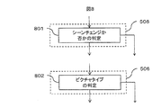
- step 506 it is determined whether or not PMV selection is performed in frame units. If PMV selection is not performed, the process proceeds to step 510; otherwise, the process proceeds to step 507. Subsequently, in step 507, it is determined whether or not PMV selection is performed in block units. If PMV selection is not performed, the process proceeds to step 510; otherwise, the process proceeds to step 508. Further, in step 508, PMV candidate blocks are adjusted to determine which blocks are included in candidate blocks and which blocks are not included depending on conditions. These processes can be switched in units of frames and blocks, and such switching may be transmitted to the decoding device side by a flag, or the same switching condition may be held in the decoding device.
- Step 801 determines whether or not to perform PMV selection by determining whether or not a scene change has occurred.
- the scene analysis process may be performed on the decoder side as described above to determine whether to perform the PMV selection process without transmitting the flag, or the determination on the encoder side may be determined on the decoder side by the flag. You may judge it.
- a specific method such as a method for obtaining PMV by median calculation or a method in which the left or upper block vector is set to PMV, is determined in advance.
- step 802 it is determined whether or not PMV selection is performed by determining the picture type. For example, if the encoding target frame is a P picture, motion vector prediction by PMV selection is performed. Otherwise, other means such as median calculation are used. It may be a B picture instead of a P picture. You may provide the flag which discriminate
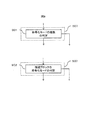
- Step 901 determines whether or not to perform PMV selection by determining the type of encoding mode of the encoding target block. For example, PMV selection may be performed only for a specific block size, or PMV selection may not be applied to Skip mode or Direct mode.
- step 902 it is determined whether or not to perform PMV selection by determining the type of encoding mode of the candidate block. For example, if all candidate blocks are in the intra coding mode, PMV selection is not performed.
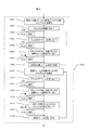
- step 1001 one candidate block of the encoding target frame, for example, one block not checked yet is selected from A and B in FIG. This is block X.
- step 1002 it is checked whether or not the block X can be referred to. If reference is impossible, the process proceeds to step 1003, and if reference is possible, the process proceeds to step 1004.
- Unreferable refers to a state in which block information cannot be acquired because the block position is out of the screen range, etc., and referable means that block information can be acquired.
- the block information includes a vector and a reference frame number. Is included.
- step 1003 block X is set to 0 vector or excluded from candidate blocks. Which one to use is predetermined. For example, in step 1003, the zero vector is set.
- a “0 vector” is a vector in which the value of each component is 0.
- step 1004 it is checked whether or not the block X has a vector. If it is an intra-coded block, it has no vector. If it has no vector, the process proceeds to step 1005. If it has a vector, the process proceeds to step 1006.
- step 1005 block X is set to 0 vector or excluded from candidate blocks. Which one to use is predetermined. For example, in step 1005, the block is excluded from the candidate blocks.
- step 1006 it is checked whether the reference frame number of the block X and the encoding target block match. For example, when the block to be encoded is unidirectional prediction and the block X is bidirectional prediction, either L0 or L1 may match. Further, when the encoding target block is bidirectional prediction and the block X is unidirectional prediction, there is a mismatch. If they do not match, the process proceeds to step 1007, and if they match, the process proceeds to step 1008.
- step 1007 block X is set to 0 vector or excluded from candidate blocks. Which one to use is predetermined. For example, in step 1007, the block is excluded from the candidate blocks.
- step 1008 it is determined whether there is another candidate block to be checked in the encoding target frame. If there is another block to be checked, the process returns to step 1001. Otherwise, go to step 1009.
- step 1009 one candidate block of the reference frame, for example, one block not checked yet is selected from S in FIG. This is block Y.
- step 1010 it is checked whether the block Y has a vector. If it is an intra-coded block, it has no vector. If it has no vector, the process proceeds to step 1011. If it has a vector, the process proceeds to step 1012.
- step 1011 block Y is set to 0 vector or excluded from candidate blocks. Which one to use is predetermined. For example, in step 1011, it is excluded from the candidate blocks.
- Step 1012 checks whether the reference frame number of the block Y and the encoding target block match. For example, when the block to be encoded is unidirectional prediction and the block Y is bidirectional prediction, either L0 or L1 may match. Further, when the encoding target block is bidirectional prediction and the block Y is unidirectional prediction, there is a mismatch. If they do not match, the process proceeds to step 1013, and if they match, the process proceeds to step 1014.
- step 1013 block Y is set to 0 vector or excluded from candidate blocks. Which one to use is predetermined. For example, in step 1013, the block is excluded from the candidate blocks.
- step 1014 it is checked whether the encoding target block or the block Y is in the bidirectional prediction mode. If either is the bidirectional prediction mode, the process proceeds to step 1015; otherwise, the process proceeds to step 1016.
- step 1015 block Y is set to 0 vector or excluded from candidate blocks. Which one to use is predetermined. For example, in step 1015, it is excluded from the candidate blocks.
- step 1016 it is determined whether there is another candidate block to be checked in the reference frame. If there is another block to be checked, the process returns to step 1009.
- steps 1003, 1005, 1007, 1011, 1013, and 1015 corresponding to each condition the process of setting the block X or the block Y to 0 vector or excluding from the candidate block was performed.
- blocks at positions C and D in FIG. 3 may be added to the candidate blocks as candidate blocks. For example, among S, A, and B, if the candidate block is 0, C and D are added to the candidate block, and if it is 1, C is added to the candidate block. C, D, and other blocks may be added to the candidate block in advance, and a vector may be selected therefrom.
- S when the picture of L0 [0] is intra-coded, S may be excluded from the candidate blocks and C may be added instead.
- block C may be used when block A cannot be referenced.
- a method predetermined by a flag may be switched for each frame or block. That is, there can be the following methods. ⁇ Unify the method to any method ⁇ Indicates which method can be switched by frame and selected by flag ⁇ Indicates which method can be switched by block and selected by flag The conditions shown in FIG. There are the following, which may change the order of determination.
- Whether the candidate block cannot be referenced ⁇ Whether the candidate block has a motion vector ⁇ Whether the candidate block and the encoding target block are different in encoding type (for example, the candidate block is encoded by bidirectional prediction (B prediction)) Target block is one-way prediction (P prediction)) -Whether the reference frame number of the candidate block and the encoding target block match-Whether the candidate block and the encoding target block are bidirectional prediction
- B prediction bidirectional prediction
- Target block is one-way prediction (P prediction))
- P prediction one-way prediction
- the methods for adjusting the candidate block include the following. ⁇ Exclude candidate block from candidate block ⁇ Process vector of candidate block as 0 vector ⁇ Add another block in encoding target frame to candidate block ⁇ Add another block in reference frame to candidate block 3. Add another block shown at 303 in the process to the candidate block.
- step 509 the PMV is selected and the difference vector is calculated and encoded.
- the PMV selects a vector closest to the vector of the encoding target block from the candidate block vectors. A vector with the smallest code amount is selected when each component of the vector is encoded.
- the selected vector is transmitted as a flag.
- the candidate blocks are arranged in order, and if it is 1 bit, the vector of the first candidate block is selected when it is 0, and the vector of the next candidate block is selected when it is 1. For example, when the A, B, and S blocks match, the candidate blocks are ordered in the order of A, B, and S. If the same vector is found, it is excluded and the two blocks from the top are arranged and compared. Will be.
- the selected vector is indicated by 2 bits. Assume that there are four candidate blocks A, B, S, and C shown in FIG. Similar to the above example, a vector closest to the vector of the encoding target block is selected, and the code is transmitted in the form of A: 0, B: 01, C: 10, S: 11. For example, if any of these is excluded from the candidate blocks, the order of the blocks is increased.
- the number of bits indicating the selected vector may be switched in units of frames or blocks. In that case, a flag indicating switching is transmitted separately.
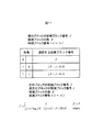
- Fig. 11 shows an example of the description method of the code of the selected vector.
- P be the candidate block number of the current previous encoding target block
- N be the number of candidate blocks.
- X be the candidate block number of the current encoding target block. If the current encoding candidate block number is P, 0 is set as the code C. Otherwise, output 1 first, and then continue to output (X-P-1)% N.
- step 506 to step 509 is executed by the adaptive PMV selection unit 106.
- step 510 PMV calculation and vector encoding are performed.
- the PMV is not selected, and the PMV is calculated by a normal median operation.
- median operation is performed on each component of the left A, upper B, upper right C, or upper left D vector to determine PMV.
- a difference vector from the vector of the encoding target block is calculated and encoded.
- the processing in step 510 is executed by the PMV predictive encoding 107.
- step 511 motion prediction is performed for each inter prediction mode, a residual component is obtained for the pixels of the encoded block, DCT transform processing, quantization processing, and entropy encoding processing of the residual component are performed, and encoded data Is calculated.
- DCT transform processing quantization processing
- entropy encoding processing of the residual component are performed, and encoded data Is calculated.
- Each process so far included in step 511 is executed by DCT transform section 108, quantization section 109, and entropy coding section 110.
- entropy decoding processing, inverse quantization, and inverse DCT conversion processing are performed from the encoded data to create a decoded image. As a result, the encoded data and the decoded image are output.
- Each process included in step 511 so far is performed by the inverse quantization unit 111 and the inverse DCT transform unit 112.
- step 512 in accordance with the processing results in steps 503 and 511, the image encoding results for the respective encoding modes are compared, and the encoding mode to be output for the block is determined.
- the process in step 512 is executed by the mode selection unit 113.
- step 513 the encoded data in the encoding mode selected in step 512 is output as an encoded stream.
- the process of step 513 is executed by the data output unit 114.
- the encoding process in the first embodiment is performed.
- the image coding apparatus and the image coding method according to the first embodiment described above inter prediction with higher accuracy and less code amount than the existing coding method is possible, and the compression efficiency is higher than that of the existing method.
- a high image encoding device and image encoding method can be realized.
- the image encoding device and the image encoding method according to the first embodiment can be applied to a recording device, a mobile phone, a digital camera, and the like using these.
- the image encoding device and the image encoding method according to the first embodiment described above it is possible to reduce the code amount of the encoded data and prevent deterioration of the image quality of the decoded image when the encoded data is decoded. It becomes possible. That is, a high compression rate and better image quality can be realized.
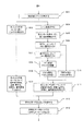
- FIG. 2 shows an example of a block diagram of an image decoding apparatus according to the second embodiment.
- the image decoding apparatus includes a stream analysis unit 201, a mode determination unit 202, a coefficient analysis unit 203, an intra prediction synthesis unit 204, an adaptive PMV selection decoding unit 205, a motion prediction synthesis unit 206, an inverse quantization unit 207, and an inverse.
- a DCT conversion unit 208, a decoded image memory 209, and an image output unit 210 are provided.
- each component of the image decoding apparatus may be an autonomous operation of each component as described below, for example. Further, for example, it may be realized by cooperating with software stored in a control unit or storage unit of a computer.
- the stream analysis unit 201 analyzes the input encoded stream.
- the stream analysis unit 201 also performs data extraction processing from packets and information acquisition processing of various headers and flags. Further, each block is processed.
- the encoded stream input to the stream analysis unit 201 is an encoded stream generated by the image encoding device and the image encoding method according to the first embodiment. Since the generation method is as shown in the first embodiment, the description is omitted. It may be an encoded stream read from the data recording medium shown in the third embodiment. The recording method will be described later.
- the mode determination unit 202 determines the encoding mode designated by a flag or the like for each block. In the following decoding process, a process corresponding to the encoding mode of the determination result is performed. The process for each encoding mode will be described below.
- the intra prediction combining unit 204 combines the intra prediction and the predicted image.
- a conventional method may be used for this method.
- the intra prediction combining unit 204 outputs the combined predicted image.
- the adaptive PMV selective decoding unit 205 adaptively selects a PMV and combines it with the decoded difference vector to restore a motion vector.
- the PMV selection method is the same as that described in the first embodiment because the encoder and decoder operate so as to select the same PMV.
- the motion prediction synthesis unit 206 performs motion prediction using the reference frame for the pixels in the block using the restored motion vector.
- the motion prediction synthesis unit 206 outputs the synthesized predicted image.
- the coefficient analysis unit 203 analyzes the encoded data of each macroblock included in the input encoded stream, and outputs the encoded data of the residual component. At this time, processing corresponding to the encoding mode of the determination result of the mode determination unit 202 is performed.
- the inverse quantization unit 207 performs inverse quantization processing on the encoded data and sends this to the inverse DCT transform unit 208.
- the inverse DCT transform unit 208 performs inverse DCT transform on the inversely quantized coefficient to restore a residual component.
- the residual component of each coding mode restored as described above is added to the prediction image output from the intra prediction synthesis unit 204 or the motion prediction synthesis unit 206, and returns to the decoded image, and is stored in the decoded image memory 209. Stored.
- the decoded image memory 209 stores information on the currently decoded frame and information on previously decoded frames, and is referred to by the intra prediction synthesis unit 204 and the motion prediction synthesis unit 206.
- the last decoded image is output by the image output unit 210, and the image is decoded.
- step 601 an encoded stream to be decoded is acquired.
- step 602 the encoding mode flag and the encoded data included in the encoded stream acquired in step 601 are analyzed. Steps 601 and 602 are executed by the stream analysis unit 201.
- step 603 the encoding mode for one encoding unit (block unit, pixel unit, etc.) included in the encoded data is determined using the encoding mode flag analyzed in step 602. If the intra coding mode is selected, the process proceeds to step 604. If the intra coding mode is selected, the process proceeds to step 605. This step 603 is executed by the mode determination unit 202.
- step 604 intra prediction is performed according to the method specified by the encoding mode. For this, an existing intra prediction method may be used.
- This step 604 is executed by the intra prediction synthesis unit 204.
- step 605 it is determined whether or not PMV selection is to be performed for the frame in accordance with various frame conditions and flag information. The determination as to whether or not to perform PMV selection for each frame is the same as the method described in the first embodiment because the encoder and the decoder operate so as to perform the same processing. If PMV selection is not performed, the process proceeds to step 609. Otherwise, the process proceeds to step 606. In step 606, it is determined whether or not PMV selection is to be performed for the block according to the encoding mode, conditions for each block, and flag information. The determination as to whether or not to perform PMV selection in block units is the same as the method described in the first embodiment because the encoder and decoder operate so as to perform the same processing. If PMV selection is not performed, the process proceeds to step 609; otherwise, the process proceeds to step 607.
- step 607 PMV candidate blocks are adjusted. Here, it is determined which block is included in the candidate block and which block is not included depending on the condition.
- the adjustment of the PMV candidate block is the same as the method described in the first embodiment because the encoder and the decoder operate so as to perform the same processing.
- step 608 PMV selection and vector decoding are performed.
- the PMV selection method is the same as the method described in the first embodiment because the encoder and the decoder operate so as to perform the same processing.
- the vector decoding the PMV and the decoded difference vector are combined to restore the motion vector of the encoding target block.
- step 609 PMV calculation and vector decoding are performed.
- the PMV calculation method is the same as the method described in the first embodiment because the encoder and the decoder operate so as to perform the same processing.
- the vector decoding the PMV and the decoded difference vector are combined to restore the motion vector of the encoding target block.
- step 610 inter prediction is performed using the restored vector and the reference frame, and a predicted image is synthesized. According to the determined coding mode, if the intra prediction synthesis unit 204 and the motion prediction synthesis unit 206 of the image decoding apparatus in FIG. 2 perform the prediction image synthesis process in each corresponding coding mode. Good. This step 610 is executed by the motion prediction synthesis unit 206.
- step 611 the predicted image and the residual component are synthesized and a decoded image is generated.
- the encoded data is analyzed, the inverse quantization process and the inverse DCT transform process are performed on the encoded data, and the residual component for the one encoding unit is decoded.
- a predicted image is synthesized with this to generate a decoded image, which is stored in a memory.
- step 612 the generated decoded image is output.
- Each processing of step 611 is executed by the coefficient analysis unit 203, the inverse quantization unit 207, the inverse DCT conversion unit 208, the decoded image memory 209, and the image output unit 210.
- an encoded stream that is defined by subdividing each encoding mode using a block size used in the encoding mode as a parameter may be set as a decoding target stream.
- inter prediction with higher accuracy and less code amount than the existing encoding method is possible, and the image has higher compression efficiency than the existing method.
- a decoding device and an image decoding method can be realized.
- the image decoding apparatus and the image decoding method according to the second embodiment can be applied to a reproducing apparatus, a mobile phone, a digital camera, and the like using them.
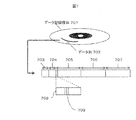
- FIG. 7 shows a data recording medium storing an encoded stream generated by the image encoding device or the image encoding method according to the first embodiment.
- the encoded stream according to the present embodiment is an encoded stream generated by the image encoding device or the image encoding method according to the first embodiment. Since the generation method is as shown in the first embodiment, the description is omitted.
- the encoded stream according to the present embodiment is recorded as a data string 702 on the data recording medium 701.
- the data string 702 is recorded as an encoded stream according to a predetermined grammar.
- the following description assumes that a part of the H.264 / AVC standard has been changed.
- a stream is composed of a sequence parameter set 703, a picture parameter set 704, and slices 705, 706, and 707.
- a case where one image (picture) is stored in one slice will be described.
- Each slice contains information 708 related to each block.
- the block-related information 708 there is an area for recording each coding mode for each block, and this is used as a coding mode flag 709.
- the data recording medium according to the third embodiment described above is recorded with the encoded stream having higher compression efficiency than the existing method, many images can be recorded.
Landscapes
- Engineering & Computer Science (AREA)
- Multimedia (AREA)
- Signal Processing (AREA)
- Compression Or Coding Systems Of Tv Signals (AREA)
Priority Applications (6)
| Application Number | Priority Date | Filing Date | Title |
|---|---|---|---|
| US13/988,819 US9781415B2 (en) | 2011-01-18 | 2012-01-16 | Image encoding method, image encoding device, image decoding method, and image decoding device |
| US15/653,793 US10271065B2 (en) | 2011-01-18 | 2017-07-19 | Image encoding method, image encoding device, image decoding method, and image decoding device |
| US16/291,234 US10743020B2 (en) | 2011-01-18 | 2019-03-04 | Image encoding method, image encoding device, image decoding method, and image decoding device |
| US16/920,871 US11290741B2 (en) | 2011-01-18 | 2020-07-06 | Image encoding method, image encoding device, image decoding method, and image decoding device |
| US17/672,817 US11758179B2 (en) | 2011-01-18 | 2022-02-16 | Image encoding method, image encoding device, image decoding method, and image decoding device |
| US18/229,263 US12114007B2 (en) | 2011-01-18 | 2023-08-02 | Image encoding method, image encoding device, image decoding method, and image decoding device |
Applications Claiming Priority (2)
| Application Number | Priority Date | Filing Date | Title |
|---|---|---|---|
| JP2011007429A JP2012151576A (ja) | 2011-01-18 | 2011-01-18 | 画像符号化方法、画像符号化装置、画像復号方法及び画像復号装置 |
| JP2011-007429 | 2011-01-18 |
Related Child Applications (2)
| Application Number | Title | Priority Date | Filing Date |
|---|---|---|---|
| US13/988,819 A-371-Of-International US9781415B2 (en) | 2011-01-18 | 2012-01-16 | Image encoding method, image encoding device, image decoding method, and image decoding device |
| US15/653,793 Continuation US10271065B2 (en) | 2011-01-18 | 2017-07-19 | Image encoding method, image encoding device, image decoding method, and image decoding device |
Publications (1)
| Publication Number | Publication Date |
|---|---|
| WO2012098845A1 true WO2012098845A1 (ja) | 2012-07-26 |
Family
ID=46515481
Family Applications (1)
| Application Number | Title | Priority Date | Filing Date |
|---|---|---|---|
| PCT/JP2012/000193 WO2012098845A1 (ja) | 2011-01-18 | 2012-01-16 | 画像符号化方法、画像符号化装置、画像復号方法及び画像復号装置 |
Country Status (3)
| Country | Link |
|---|---|
| US (6) | US9781415B2 (sl) |
| JP (1) | JP2012151576A (sl) |
| WO (1) | WO2012098845A1 (sl) |
Cited By (1)
| Publication number | Priority date | Publication date | Assignee | Title |
|---|---|---|---|---|
| WO2014173092A1 (zh) * | 2013-04-26 | 2014-10-30 | 华为技术有限公司 | 一种图像预测编码方法及图像编码器 |
Families Citing this family (7)
| Publication number | Priority date | Publication date | Assignee | Title |
|---|---|---|---|---|
| JP2012151576A (ja) | 2011-01-18 | 2012-08-09 | Hitachi Ltd | 画像符号化方法、画像符号化装置、画像復号方法及び画像復号装置 |
| US9319716B2 (en) * | 2011-01-27 | 2016-04-19 | Qualcomm Incorporated | Performing motion vector prediction for video coding |
| EP3739884B1 (en) * | 2011-06-27 | 2021-08-04 | Samsung Electronics Co., Ltd. | Encoding and decoding motion information |
| EP3024242A4 (en) * | 2013-07-18 | 2017-01-11 | LG Electronics Inc. | Method and apparatus for processing video signal |
| CN104717510B (zh) | 2013-12-13 | 2018-08-17 | 华为技术有限公司 | 用于图像处理的方法和装置 |
| FR3047379A1 (fr) * | 2016-01-29 | 2017-08-04 | Orange | Procede de codage et decodage de donnees, dispositif de codage et decodage de donnees et programmes d'ordinateur correspondants |
| US10958928B2 (en) * | 2018-04-10 | 2021-03-23 | Qualcomm Incorporated | Decoder-side motion vector derivation for video coding |
Citations (3)
| Publication number | Priority date | Publication date | Assignee | Title |
|---|---|---|---|---|
| JP2007504760A (ja) * | 2003-09-07 | 2007-03-01 | マイクロソフト コーポレーション | インターレース・ビデオおよびプログレッシブ・ビデオのマクロブロックおよび動き情報の符号化および復号における新機軸 |
| JP2008211697A (ja) * | 2007-02-28 | 2008-09-11 | Sharp Corp | 符号化装置及び復号装置 |
| WO2009093672A1 (ja) * | 2008-01-23 | 2009-07-30 | Sony Corporation | 符号化装置および方法、並びに復号装置および方法 |
Family Cites Families (33)
| Publication number | Priority date | Publication date | Assignee | Title |
|---|---|---|---|---|
| US5812197A (en) * | 1995-05-08 | 1998-09-22 | Thomson Consumer Electronics, Inc. | System using data correlation for predictive encoding of video image data subject to luminance gradients and motion |
| JP3297293B2 (ja) * | 1996-03-07 | 2002-07-02 | 三菱電機株式会社 | 動画像復号方法および動画像復号装置 |
| US7978769B2 (en) * | 2003-06-30 | 2011-07-12 | Ntt Docomo, Inc. | Method and apparatus for coding motion information |
| DE602005015067D1 (de) * | 2004-09-30 | 2009-08-06 | Toshiba Kk | Informationsbearbeitungsgerät und Programm |
| US8913660B2 (en) * | 2005-04-14 | 2014-12-16 | Fastvdo, Llc | Device and method for fast block-matching motion estimation in video encoders |
| KR100770704B1 (ko) * | 2005-08-04 | 2007-10-29 | 삼성전자주식회사 | 픽쳐 스킵 방법 및 장치 |
| US8059719B2 (en) * | 2005-09-16 | 2011-11-15 | Sony Corporation | Adaptive area of influence filter |
| US7957466B2 (en) * | 2005-09-16 | 2011-06-07 | Sony Corporation | Adaptive area of influence filter for moving object boundaries |
| US7894527B2 (en) * | 2005-09-16 | 2011-02-22 | Sony Corporation | Multi-stage linked process for adaptive motion vector sampling in video compression |
| US7894522B2 (en) * | 2005-09-16 | 2011-02-22 | Sony Corporation | Classified filtering for temporal prediction |
| US8005308B2 (en) * | 2005-09-16 | 2011-08-23 | Sony Corporation | Adaptive motion estimation for temporal prediction filter over irregular motion vector samples |
| US7596243B2 (en) * | 2005-09-16 | 2009-09-29 | Sony Corporation | Extracting a moving object boundary |
| JP5018074B2 (ja) * | 2006-12-22 | 2012-09-05 | 富士通セミコンダクター株式会社 | メモリ装置,メモリコントローラ及びメモリシステム |
| JP2008167061A (ja) * | 2006-12-27 | 2008-07-17 | Toshiba Corp | 符号化装置及び符号化方法 |
| KR101353301B1 (ko) * | 2008-04-11 | 2014-01-21 | 에스케이 텔레콤주식회사 | 인트라 예측 모드 결정 방법 및 그 장치와 이를 이용한영상 부호화/복호화 방법 및 그 장치 |
| KR101361005B1 (ko) * | 2008-06-24 | 2014-02-13 | 에스케이 텔레콤주식회사 | 인트라 예측 방법 및 장치와 그를 이용한 영상부호화/복호화 방법 및 장치 |
| JP2010016453A (ja) * | 2008-07-01 | 2010-01-21 | Sony Corp | 画像符号化装置および方法、画像復号装置および方法、並びにプログラム |
| JP5166156B2 (ja) * | 2008-07-25 | 2013-03-21 | 株式会社東芝 | 解像度変換装置、方法およびプログラム |
| US20110164684A1 (en) * | 2008-09-24 | 2011-07-07 | Sony Corporation | Image processing apparatus and method |
| JPWO2010035731A1 (ja) * | 2008-09-24 | 2012-02-23 | ソニー株式会社 | 画像処理装置および方法 |
| JP5422168B2 (ja) * | 2008-09-29 | 2014-02-19 | 株式会社日立製作所 | 動画像符号化方法および動画像復号化方法 |
| JP5277257B2 (ja) * | 2008-12-03 | 2013-08-28 | 株式会社日立製作所 | 動画像復号化方法および動画像符号化方法 |
| US20100220215A1 (en) * | 2009-01-12 | 2010-09-02 | Jorge Rubinstein | Video acquisition and processing systems |
| JP2011082683A (ja) * | 2009-10-05 | 2011-04-21 | Sony Corp | 画像処理装置、画像処理方法、及び、プログラム |
| KR101611437B1 (ko) * | 2009-10-28 | 2016-04-26 | 삼성전자주식회사 | 복수의 프레임을 참조하여 영상을 부호화, 복호화하는 방법 및 장치 |
| JP5321439B2 (ja) * | 2009-12-15 | 2013-10-23 | 株式会社Jvcケンウッド | 画像符号化装置、画像復号化装置、画像符号化方法、及び、画像復号化方法 |
| US9467705B2 (en) * | 2009-12-30 | 2016-10-11 | Ariscale Inc. | Video encoding apparatus, video decoding apparatus, and video decoding method for performing intra-prediction based on directionality of neighboring block |
| US9237355B2 (en) * | 2010-02-19 | 2016-01-12 | Qualcomm Incorporated | Adaptive motion resolution for video coding |
| JP5368631B2 (ja) * | 2010-04-08 | 2013-12-18 | 株式会社東芝 | 画像符号化方法、装置、及びプログラム |
| WO2012008037A1 (ja) * | 2010-07-15 | 2012-01-19 | 富士通株式会社 | 動画像復号装置、動画像復号方法及び動画像符号化装置ならびに動画像符号化方法 |
| US8344917B2 (en) * | 2010-09-30 | 2013-01-01 | Sharp Laboratories Of America, Inc. | Methods and systems for context initialization in video coding and decoding |
| US9313514B2 (en) * | 2010-10-01 | 2016-04-12 | Sharp Kabushiki Kaisha | Methods and systems for entropy coder initialization |
| JP2012151576A (ja) * | 2011-01-18 | 2012-08-09 | Hitachi Ltd | 画像符号化方法、画像符号化装置、画像復号方法及び画像復号装置 |
-
2011
- 2011-01-18 JP JP2011007429A patent/JP2012151576A/ja active Pending
-
2012
- 2012-01-16 WO PCT/JP2012/000193 patent/WO2012098845A1/ja active Application Filing
- 2012-01-16 US US13/988,819 patent/US9781415B2/en active Active
-
2017
- 2017-07-19 US US15/653,793 patent/US10271065B2/en active Active
-
2019
- 2019-03-04 US US16/291,234 patent/US10743020B2/en active Active
-
2020
- 2020-07-06 US US16/920,871 patent/US11290741B2/en active Active
-
2022
- 2022-02-16 US US17/672,817 patent/US11758179B2/en active Active
-
2023
- 2023-08-02 US US18/229,263 patent/US12114007B2/en active Active
Patent Citations (3)
| Publication number | Priority date | Publication date | Assignee | Title |
|---|---|---|---|---|
| JP2007504760A (ja) * | 2003-09-07 | 2007-03-01 | マイクロソフト コーポレーション | インターレース・ビデオおよびプログレッシブ・ビデオのマクロブロックおよび動き情報の符号化および復号における新機軸 |
| JP2008211697A (ja) * | 2007-02-28 | 2008-09-11 | Sharp Corp | 符号化装置及び復号装置 |
| WO2009093672A1 (ja) * | 2008-01-23 | 2009-07-30 | Sony Corporation | 符号化装置および方法、並びに復号装置および方法 |
Non-Patent Citations (1)
| Title |
|---|
| FRANK BOSSEN ET AL.: "Simplified motion vector coding method", JOINT COLLABORATIVE TEAM ON VIDEO CODING (JCT-VC) OF ITU-T SG16 WP3 AND ISO/IEC JTC1/SC29/WG11, JCTVC-B094, 2ND MEETING, July 2010 (2010-07-01), GENEVA, CH, pages 1 - 5 * |
Cited By (1)
| Publication number | Priority date | Publication date | Assignee | Title |
|---|---|---|---|---|
| WO2014173092A1 (zh) * | 2013-04-26 | 2014-10-30 | 华为技术有限公司 | 一种图像预测编码方法及图像编码器 |
Also Published As
| Publication number | Publication date |
|---|---|
| US9781415B2 (en) | 2017-10-03 |
| US12114007B2 (en) | 2024-10-08 |
| US20190200035A1 (en) | 2019-06-27 |
| US20200336759A1 (en) | 2020-10-22 |
| US10743020B2 (en) | 2020-08-11 |
| US20230388537A1 (en) | 2023-11-30 |
| JP2012151576A (ja) | 2012-08-09 |
| US20170318307A1 (en) | 2017-11-02 |
| US20130243097A1 (en) | 2013-09-19 |
| US11758179B2 (en) | 2023-09-12 |
| US11290741B2 (en) | 2022-03-29 |
| US20220174311A1 (en) | 2022-06-02 |
| US10271065B2 (en) | 2019-04-23 |
Similar Documents
| Publication | Publication Date | Title |
|---|---|---|
| US11758179B2 (en) | Image encoding method, image encoding device, image decoding method, and image decoding device | |
| JP4542447B2 (ja) | 画像の符号化/復号化装置、符号化/復号化プログラム及び符号化/復号化方法 | |
| KR101662139B1 (ko) | 고효율 비디오 코딩을 위한 움직임 정보의 효율적인 저장 | |
| KR101833933B1 (ko) | 동화상 예측 부호화 장치, 동화상 예측 부호화 방법, 동화상 예측 부호화 프로그램, 동화상 예측 복호 장치, 동화상 예측 복호 방법 및 동화상 예측 복호 프로그램 | |
| JP2002125236A (ja) | 動きベクトル変換方法及び変換装置 | |
| KR20140029383A (ko) | 화상 부호화 장치 및 화상 복호 장치 | |
| WO2010070818A1 (ja) | 動画像符号化装置、動画像符号化方法、動画像復号化装置および動画像復号化方法 | |
| WO2006035584A1 (ja) | 符号化装置、符号化方法、符号化方法のプログラム及び符号化方法のプログラムを記録した記録媒体 | |
| JP2007251497A (ja) | 動画像符号化方法、動画像符号化装置、動画像符号化プログラム | |
| JP2009089332A (ja) | 動き予測方法及び動き予測装置 | |
| CN113615173A (zh) | 对仿射译码块进行光流预测修正的方法及装置 | |
| KR20240072202A (ko) | 비디오 코딩 및 디코딩 | |
| JP6181242B2 (ja) | 画像復号化方法 | |
| JP5946980B1 (ja) | 画像復号化方法 | |
| JP5951915B2 (ja) | 画像復号化方法 | |
| JP5911982B2 (ja) | 画像復号化方法 | |
| JP5750191B2 (ja) | 画像復号化方法 | |
| JP4561701B2 (ja) | 動画像符号化装置 | |
| KR20240112899A (ko) | 비디오 코딩에서 아핀 병합 모드의 후보 도출을 위한 방법 및 장치 | |
| JP2024534644A (ja) | Mdmvrベースの映像コーディング方法及び装置 | |
| WO2024064422A1 (en) | Method and apparatus for implicitly indicating motion vector predictor precision | |
| CN115668934A (zh) | 具有基于层间预测确定的运动信息的图像编码/解码方法和设备及发送比特流的方法 | |
| CN116325735A (zh) | 用于针对参考帧进行自适应重新排序的方法和装置 | |
| JP2012257323A (ja) | 画像の符号化/復号化装置、符号化/復号化プログラム及び符号化/復号化方法 | |
| JP2012138837A (ja) | 動画像符号化装置、動画像符号化方法、及び動画像符号化プログラム |
Legal Events
| Date | Code | Title | Description |
|---|---|---|---|
| 121 | Ep: the epo has been informed by wipo that ep was designated in this application |
Ref document number: 12736711 Country of ref document: EP Kind code of ref document: A1 |
|
| DPE1 | Request for preliminary examination filed after expiration of 19th month from priority date (pct application filed from 20040101) | ||
| WWE | Wipo information: entry into national phase |
Ref document number: 13988819 Country of ref document: US |
|
| NENP | Non-entry into the national phase |
Ref country code: DE |
|
| 122 | Ep: pct application non-entry in european phase |
Ref document number: 12736711 Country of ref document: EP Kind code of ref document: A1 |