WO2012098809A1 - 防氷装置、翼、航空機および防氷方法 - Google Patents
防氷装置、翼、航空機および防氷方法 Download PDFInfo
- Publication number
- WO2012098809A1 WO2012098809A1 PCT/JP2011/080044 JP2011080044W WO2012098809A1 WO 2012098809 A1 WO2012098809 A1 WO 2012098809A1 JP 2011080044 W JP2011080044 W JP 2011080044W WO 2012098809 A1 WO2012098809 A1 WO 2012098809A1
- Authority
- WO
- WIPO (PCT)
- Prior art keywords
- aircraft
- icing
- ice
- pressure
- sound
- Prior art date
- Legal status (The legal status is an assumption and is not a legal conclusion. Google has not performed a legal analysis and makes no representation as to the accuracy of the status listed.)
- Ceased
Links
Images



Classifications
-
- B—PERFORMING OPERATIONS; TRANSPORTING
- B64—AIRCRAFT; AVIATION; COSMONAUTICS
- B64D—EQUIPMENT FOR FITTING IN OR TO AIRCRAFT; FLIGHT SUITS; PARACHUTES; ARRANGEMENT OR MOUNTING OF POWER PLANTS OR PROPULSION TRANSMISSIONS IN AIRCRAFT
- B64D15/00—De-icing or preventing icing on exterior surfaces of aircraft
Definitions
- the present invention relates to an anti-icing device, a wing, an aircraft, and an anti-icing method for preventing icing on an aircraft flying in a flying environment under icing conditions.
- Aircraft may have an event that when the aircraft is parked, the snow that has accumulated on the aircraft melts once and then sticks to the aircraft, or the rain turns into snow and the temperature drops, causing ice to stick to the aircraft.
- the aircraft must deal with it during flight.
- the aircraft flies in clouds or rain containing water droplets, the aircraft gets wet, but the water drops are blown away by the air pressure due to the speed of the aircraft, even if the heat of vaporization is taken away and it does not matter .
- Icing is a problem when the aircraft must fly under supercooled water conditions that exist in a liquid state despite the microscopic water droplets forming a cloud below zero.
- the minute water droplets move in the direction avoiding the aircraft due to the air flow, depending on the aircraft speed and the size of the minute water droplets, they can not be avoided and hit the aircraft. Ice develops in front of the wing, especially on the leading edge of the wing. If this happens, the wing shape changes and the lift of the aircraft decreases, and the effectiveness of the rudder may be hindered, leading to unstable flight.
- Patent Document 1 discloses a technique for preventing icing by heating an aircraft anti-icing surface with high-temperature air from an engine.
- the conventional anti-icing / de-icing device has a problem in that it has a large area, a large amount of energy is required, and a weight increases because the area of the main wing and the like to prevent icing is large. For this reason, large aircrafts are the mainstream that can be equipped with anti-icing / deicing devices, and lightweight small aircrafts do not have anti-icing / deicing devices, so they cannot fly in an icing environment for safety reasons. In order to maintain the high mobility of fighters, as a result of pursuing thin wing thickness and light weight, there is usually an anti-icing device around the engine, but no other parts are equipped. For this reason, after the fighter jets rise to the sky, if the sky over the base of the planned landing site is in a strong icing environment, the landing site is forced to change.
- the present invention has been made in view of such circumstances, and has a simple configuration, an anti-icing device that prevents icing on an aircraft flying in a flying environment under icing conditions, a wing, an aircraft, and An object is to provide an anti-icing method.
- the anti-icing device, wing, aircraft and anti-icing method of the present invention employ the following means. That is, the anti-icing device according to the first aspect of the present invention outputs a pressure wave toward a water droplet floating in the air existing in the traveling direction of the aircraft and being in a supercooled state, and the water droplet is caused to drop by the pressure wave. Change to ice.
- the water droplet when there is a water droplet floating in the air and being in a supercooled state in the traveling direction of the aircraft, the water droplet is generated by outputting a pressure wave before the aircraft wing contacts the water droplet. It can be changed to ice, preventing icing on the wings of the aircraft.
- the pressure wave positively changes the water droplets to ice so that the water droplets can be removed from the air in the direction of travel, so that the ice does not adhere to the wing.
- the pressure wave is, for example, a sound wave.
- the anti-icing device is 0.9 to 3 at a predetermined position ahead of the airframe toward the water droplet floating in the air existing in the traveling direction of the aircraft and being in a supercooled state.
- a pressure wave in the range of 3 [Pa] is generated.
- a pressure wave is output before the aircraft wing contacts the water droplets.
- an acceleration of 10 G can be applied to the water droplet.
- the wing according to the third aspect of the present invention is provided with the anti-icing device described above.
- the anti-icing device provided on the wing when the aircraft is flying, the anti-icing device provided on the wing outputs a pressure wave toward a water droplet in a supercooled state existing in the traveling direction of the aircraft.
- the water droplets can be changed to ice in advance, and icing on the wings can be prevented.
- the aircraft according to the fourth aspect of the present invention is provided with an anti-icing device.
- the anti-icing device provided in the aircraft outputs a pressure wave toward the water droplet floating in the air that may collide with the wing of the aircraft and being in a supercooled state.
- the aircraft includes both aircraft having fixed wings and aircraft having rotor wings.
- the anti-icing method outputs a pressure wave toward water droplets floating in the air existing in the traveling direction of the aircraft and in a supercooled state, and Change to ice.
- the water drop when there is a water droplet floating in the air and being in a supercooled state in the traveling direction of the aircraft, the water drop is generated by outputting a pressure wave before the aircraft wing contacts the water droplet.
- the pressure wave output may be realized by an explosion of explosives.
- the pressure wave in the advancing direction of the airplane, the pressure wave is positively generated before the ice drops adhere to the wing by colliding with the wing by causing the explosive to explode in advance and outputting the pressure wave. Since the water droplets can be changed into ice and the water droplets can be removed from the air in the traveling direction, the ice does not adhere to the wing of the aircraft.
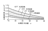
- FIG. 3 is a cross-sectional view taken along line AA in FIG. 2. It is a perspective view which shows the sound wave generator of this invention. It is a graph which shows the relationship between water droplet content [gr / m ⁇ 3 >] and water droplet diameter [micrometer] in an icing area
- the present invention solidifies the supercooled water over a wide range before contacting the aircraft body, and makes the flight environment dry. Since supercooled water is unstable, it has the property of becoming ice for stabilization when subjected to an impact.
- An object of the present invention is to take advantage of this property and actively remove supercooled water from ice to remove icing water from the flight environment and prevent icing on the aircraft.
- the aircraft targeted by the present invention is not limited to those having fixed wings, but includes those having rotating wings.
- Sonic generator 1 uses supersonic waves (pressure waves) to actively make supercooled water into ice, thereby removing icing water from the flight environment and preventing icing on aircraft To do.
- supersonic waves pressure waves
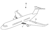
- FIG. 1 is a perspective view showing an aircraft 10 equipped with a sound wave generator 1 of the present invention.
- FIG. 1 shows the case where the sound wave generator 1 is installed on the main wing 11, the sound wave generator 1 of the present invention is limited to the main wing 11 as long as the sound wave can be emitted in front of the aircraft 10. Not.
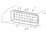
- FIG. 2 is a perspective view showing the sound wave generator 1 of the present invention.
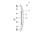
- 3 is a cross-sectional view taken along line AA in FIG.
- the sound wave generator 1 includes a plurality of sound wave generation sources 2 arranged in the front edge of the main wing 11 of the airframe, and emits sound waves in a planar shape. Further, a parabolic reflector 3 is provided around and behind the plurality of sound wave generation sources 2 to prevent the sound waves from spreading.
- a cover is necessary on the front surface of the plurality of sound wave generation sources 2. Actually, the sound wave is attenuated due to this cover, but is not particularly mentioned in this specification.
- the above-described sound wave generator 1 includes a plurality of sound wave source 2 arranged side by side, and can emit sound waves individually.
- the direction of high intensity in sound wave radiation can be moved up, down, left and right.
- the function of moving the radiation direction of the high-intensity sound wave the sound wave is scanned within the plane through which the body of the aircraft 10 passes.
- the sound wave generated by the sound wave generator 1 is generated at a predetermined position ahead of the aircraft with sound pressure 3 [Pa] and sound intensity 100 [dB] in consideration of attenuation, for example. If it is this magnitude
- the impact value in which supercooled water droplets floating in the air in the form of clouds become ice is easily solidified by pouring supercooled water into the glass or sliding your hand when pouring it. For this reason, even supercooled water droplets become solid when acceleration of 5G is applied as an impact.
- Equation 1 a force acting on a water droplet having a diameter D is expressed by the following Equation 1.
- F P ⁇ ( ⁇ D 2/ 4) whereas ( Equation 1)
- P P MAX sin ( ⁇ t)
- P MAX maximum fluctuating pressure
- () is the projected area of the water droplet.
- Equation 2 the force F when the acceleration ⁇ acts is expressed by Equation 2 below.
- ⁇ density
- parentheses are the volume of water droplets.
- each sound pressure [Pa] or sound intensity [dB] necessary for balance of force is as shown in the following table.
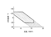
- 5 to 8 are defined as icing conditions in FAR 25 (Federal Aviation Regulations (FAR) Part 25 of the Federal Aviation Administration (FAA)).
- FAR 25 Federal Aviation Regulations
- FAR Federal Aviation Regulations
- FIGS. 5 and 6 are for the case where the cloud extends over a wide area (20 miles).
- the icing area “continuous” is displayed.
- the icing conditions shown in FIG. 7 and FIG. 8 are for the case where the cloudy area (3 miles) is narrow but the amount of water droplets in the cloud is large.
- the icing area is indicated as “intermittent”.
- FIGS. 6 and 8 show the atmospheric temperature [° F.] and the atmospheric pressure altitude [1000 Ft]. It is a graph which shows a relationship.
- the icing altitude is usually 20 [kft] or less and at most 30 [kft] or less. Therefore, since the flight speed of the aircraft 10 is considered to be slower than the sound speed at this altitude, it is determined that it is possible to control the supercooled water so as not to contact the aircraft with water droplets by using the present invention.
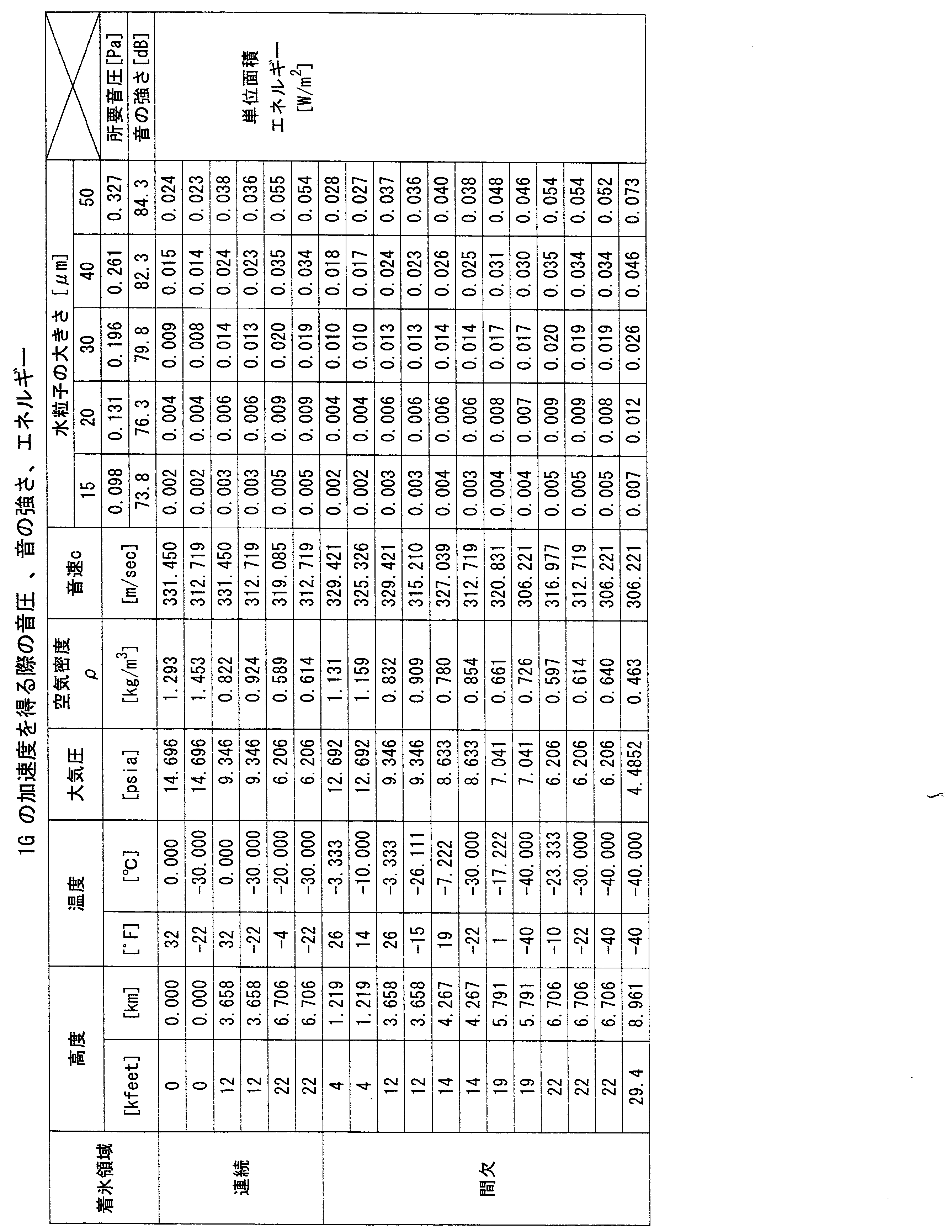
- the required sound pressure [Pa], the sound intensity [dB], and the energy [W / m 2 ] passed per unit area when the supercooled water obtains an acceleration of 1 G are as shown in the table below.
- the required sound pressure [Pa], the sound intensity [dB], and the energy [W / m 2 ] passing per unit area when the supercooled water obtains an acceleration of 5 G are as shown in the table below.
- the required sound pressure [Pa], the sound intensity [dB], and the energy [W / m 2 ] passed per unit area when the supercooled water obtains an acceleration of 10 G are as shown in the table below.
- the sound pressure required for the supercooled water to obtain an acceleration of 10 G is about 0.9 to 3.3 [Pa], and the sound intensity is about 93 to 105 [dB]. Since the energy passing per unit area is about 0.2 to 7.5 [W / m 2 ], the sound wave generator 1 takes into account the area in front of the target aircraft in consideration of attenuation. A pressure wave having a sound wave of 0.9 to 3.3 [Pa] may be generated. The sound pressure required for the supercooled water to obtain 5G acceleration is about 0.4 to 1.7 [Pa], and the sound intensity is about 87 to 99 [dB]. The energy passing per area is about 0.05 to 1.9 [W / m 2 ].
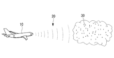
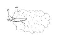
- the sound wave generator 1 is disposed in front of the aircraft 10, and as shown in FIG. 9, the sound wave generator 1 emits the sound wave 20 toward the front flight environment, particularly the supercooled water 30. And according to the sound wave generator 1 of this invention, the supercooled water of the wide area
- FIG. 9 is an explanatory diagram showing the aircraft 10 in flight and the supercooled water 30 in the flight environment
- FIG. 10 is an explanatory diagram showing the aircraft 10 in flight and the ice 40 in the flight environment.
- the sound wave generation device 21 of FIG. 4 is an example of an anti-icing device, and a plurality of sound wave generation sources 22 are provided inside the outer plate 23 of the main wing 11 of the aircraft 10.
- the sound wave generator 21 outputs sound waves directly from the outer plate 23 using the outer plate 23 of the machine body.
- the sound wave generator 21 is installed at the same position as the sound wave generator 1 in the front part of the aircraft 10 shown in FIG. 1 and radiates sound waves forward of the airframe.
- the sound wave is an example of a pressure wave.
- the sound wave generator 21 divides a portion where sound waves are emitted into a plurality of parts. Then, by the phase control, the sound wave can be emitted so that the pressure of the sound wave becomes stronger in a specific direction.
- the sound wave generators 1 and 21 of the present invention when installing the sound wave generators 1 and 21 of the present invention in an aircraft having a rotary wing such as a helicopter, the sound wave generators 1 and 21 are installed, for example, in the front part or the leg part of the fuselage.
- an anti-icing method according to the second embodiment of the present invention will be described.
- the present invention is not limited to this example.
- a facility equipped with an anti-icing device may be provided on the ground in addition to the aircraft 10 that wants to prevent icing.
- the same device as the anti-icing device mounted on the aircraft 10 is installed on the ground, the area to be covered is too large, which is not realistic.
- this device cannot be used when there is an aircraft nearby because the pressure wave may be too strong depending on the amount of explosives to damage the aircraft. Therefore, it was estimated whether the energy required for the supercooled water to turn into ice due to the sound pressure due to the explosion of the explosive could be generated with a common amount of explosive.
- the weight of explosives required to generate 2 [W / m 2 ] when the cloud spread is 20 [mile] is calculated.
- 20 [mile] 32, 186.2 [m]
- the pressure that causes damage to the structure is shown separately in Wikipedia's "blast", and this pressure reaches about 1000 times or more the pressure required to change the supercooled water to ice. From this, when the distance that matches this condition was calculated, the pressure range causing damage to the structure was about 1 [km] under the condition that the supercooled water in the range of 20 [mile] was changed to ice. When a pressure higher than the pressure necessary for changing the supercooled water to ice is generated at the position of 20 [mile], the range of pressure at which the structure is damaged is further widened.
- the explosive energy efficiency that changes to pressure is set to 10 [%] in order to consider the amount of explosives safely, and the amount of explosives is actually confirmed by testing from the safety aspect due to the blast. Need to reduce.
- the present invention completely differs from the conventional method in that the supercooled water itself that causes icing is extinguished from the environment.
- the anti-icing device and anti-icing method of the present invention are relatively cheap, lightweight, and have less energy than other methods.
- the sound wave generator 1 according to the first embodiment has an advantage that the mounting position does not need to be at a position where it is desired to prevent icing.
- the aircraft 10 equipped with the sound wave generator 1 can also support safe landing by flying in front of an aircraft not equipped with the anti-icing device.
Landscapes
- Engineering & Computer Science (AREA)
- Aviation & Aerospace Engineering (AREA)
- Buildings Adapted To Withstand Abnormal External Influences (AREA)
- Catching Or Destruction (AREA)
Abstract
簡易な構成で、着氷条件下にある飛行環境を飛行する航空機への着氷を防止する防氷装置、翼、航空機および防氷方法を提供することを目的とする。本発明に係る防氷装置は、航空機(10)の進行方向に存在する空気中に浮遊し過冷却状態にある水滴に向けて圧力波を出力し、前記圧力波によって前記水滴を氷に変化させる。圧力波は例えば10Gの加速度を水滴に与える場合、減衰を考慮し所定の位置で0.9~3.3[Pa]である。
Description
本発明は、着氷条件下にある飛行環境を飛行する航空機への着氷を防止する防氷装置、翼、航空機および防氷方法に関するものである。
航空機は、駐機時には機体に積もった雪が一度溶けてから機体にくっついたり、雨から雪に変わり気温が下がって機体に氷がこびりついたりする事象がある。この場合は、機体側ではなく、地上装備として80[℃]程度に暖めたエチレングリコールやイソプロピルアルコールを機体に振りかけ溶かす設備があり、機体側はさほど問題とならない。
一方、飛行時には機体側で対処が求められる。機体が水滴を含む雲の中や雨の中を飛行する際に機体は濡れるものの機速による空気圧により水滴は吹き飛ばされ、たとえ気化熱が奪われて零下になったとしても問題となることはない。
着氷が問題となるのは、雲を形成する微小水滴が零下にもかかわらず液体の状態で存在する過冷却水の条件下を、航空機が飛行しなくてはならなくなった時である。この場合、微小水滴は空気流により機体を避ける方向に移動するものの、機速や微小水滴の大きさによっては避けきれずに機体にぶつかり、その時の衝撃で過冷却水が固体化して氷となり機体の前方、特に翼前縁に氷が付着・発達する。そうなると、翼形状が変化し航空機の揚力が減少するとともに、舵の効きを妨げ、不安定な飛行を招くおそれがある。
翼への着氷を防止するため、防氷・除氷装置が着氷の可能性がある翼前方部やエンジンの空気取り入れ口に装備される。防氷・除氷装置には、ヒータやブリード・エアの熱を利用するもの、ゴム製のブーツや電磁コイルにより翼や空気取り入れ口の外部形状の変形を利用するもの、除氷液を滲出させるもの等がある。特許文献1では、エンジンからの高温空気によって航空機防氷表面を加熱し着氷を防止する技術が開示されている。
従来の防氷・除氷装置は、主翼等の着氷防止対象とする部分の面積が大きいことから、大型化すると共に、必要とするエネルギーが大きく、重量が増加するという問題があった。そのため、防氷・除氷装置を装着できる機体は大型機が主流であり、軽量の小型機等は防氷・除氷装置がないため、安全上、着氷環境下において飛行できない。戦闘機はその高運動性を維持する目的から、翼厚さが薄く、且つ軽量を追求する結果、通常エンジン廻りの着氷防止装置はあるもののその他の部分には装備されていない。そのため、戦闘機は上空に上がった後、着陸予定地の基地上空が強い着氷環境下になると、着陸予定地の変更を余儀なくされる。
本発明は、このような事情に鑑みてなされたものであって、簡易な構成で、着氷条件下にある飛行環境を飛行する航空機への着氷を防止する防氷装置、翼、航空機および防氷方法を提供することを目的とする。
上記課題を解決するために、本発明の防氷装置、翼、航空機および防氷方法は以下の手段を採用する。
すなわち、本発明の第1の態様に係る防氷装置は、航空機の進行方向に存在する空気中に浮遊し過冷却状態にある水滴に向けて圧力波を出力し、前記圧力波によって前記水滴を氷に変化させる。
すなわち、本発明の第1の態様に係る防氷装置は、航空機の進行方向に存在する空気中に浮遊し過冷却状態にある水滴に向けて圧力波を出力し、前記圧力波によって前記水滴を氷に変化させる。
前記第1の態様によれば、航空機の進行方向において、空気中に浮遊し過冷却状態にある水滴が存在するとき、航空機の翼が水滴に接触する前に圧力波を出力することによって水滴を氷に変化させることができ、航空機の翼への着氷を防止できる。すなわち、過冷却状態にある水滴は不安定な状態にあるため、水滴に衝撃が加わると安定化のため氷となるが、本発明では、水滴が翼に衝突することで翼に氷が付着する前に、圧力波が積極的に水滴を氷に変化させて、水滴を進行方向の空気中から排除できるため、翼に氷が付着することはない。ここで、圧力波は、例えば音波である。
また、本発明の第2の態様に係る防氷装置は、航空機の進行方向に存在する空気中に浮遊し過冷却状態にある水滴に向けて機体よりも前方の所定位置において0.9~3.3[Pa]の範囲にある圧力波を発生させる。
前記第2の態様によれば、航空機の進行方向において、空気中に浮遊し過冷却状態にある15~50μmの水滴が存在するとき、航空機の翼が水滴に接触する前に圧力波を出力することによって0.9~3.3[Pa]の圧力場を作り出した場合、水滴に加速度10Gを与えることができる。このように水滴に加速度を加えることにより、水滴を氷に変化させることができ、航空機の翼への着氷を防止できる。
さらに、本発明の第3の態様に係る翼は、上記の防氷装置が設けられる。
前記第3の態様によれば、航空機が飛行している際に、翼に設けられた防氷装置が航空機の進行方向に存在する過冷却状態にある水滴に向けて圧力波を出力することで、予め水滴を氷に変化させることができ、翼等への着氷を防止できる。
前記第3の態様によれば、航空機が飛行している際に、翼に設けられた防氷装置が航空機の進行方向に存在する過冷却状態にある水滴に向けて圧力波を出力することで、予め水滴を氷に変化させることができ、翼等への着氷を防止できる。
またさらに、本発明の第4の態様に係る航空機は、防氷装置が設けられる。
前記第4の態様によれば、航空機に設けられた防氷装置が、該航空機の翼に衝突する可能性のある空気中に浮遊し過冷却状態にある水滴に向けて圧力波を出力することで、航空機の翼への着氷を防止できる。ここで、航空機は固定翼を有する航空機と回転翼を有する航空機の両方を含む。
前記第4の態様によれば、航空機に設けられた防氷装置が、該航空機の翼に衝突する可能性のある空気中に浮遊し過冷却状態にある水滴に向けて圧力波を出力することで、航空機の翼への着氷を防止できる。ここで、航空機は固定翼を有する航空機と回転翼を有する航空機の両方を含む。
また、本発明の第5の態様に係る防氷方法は、航空機の進行方向に存在する空気中に浮遊し過冷却状態にある水滴に向けて圧力波を出力し、前記圧力波によって前記水滴を氷に変化させる。
前記第5の態様によれば、航空機の進行方向において、空気中に浮遊し過冷却状態にある水滴が存在するとき、航空機の翼が水滴に接触する前に圧力波を出力することによって水滴を氷に変化させて、水滴を進行方向の空気中から排除できるため、航空機の翼への着氷を防止できる。
前記第5の態様において、前記圧力波の出力は火薬の爆発によって実現されてもよい。
前記第5の態様によれば、飛行機の進行方向において、予め火薬を爆発させて圧力波を出力することで、水滴が翼に衝突することで翼に氷が付着する前に、圧力波が積極的に水滴を氷に変化させて、水滴を進行方向の空気中から排除できるため、航空機の翼に氷が付着することはない。
前記第5の態様によれば、飛行機の進行方向において、予め火薬を爆発させて圧力波を出力することで、水滴が翼に衝突することで翼に氷が付着する前に、圧力波が積極的に水滴を氷に変化させて、水滴を進行方向の空気中から排除できるため、航空機の翼に氷が付着することはない。
本発明によれば、簡易な構成で、着氷条件下にある飛行環境を飛行する航空機への着氷を防止することができる。
以下、本発明に係る防氷装置、防氷方法の実施形態について説明する。
本発明は、航空機の機体に接触する前に広範囲にわたって過冷却水を固体化させ、飛行環境を乾燥状態とするものである。過冷却水は不安定なため、衝撃が加われば、安定化のため氷となる性質がある。本発明はこの性質を利用し、過冷却水を積極的に氷にすることにより、着氷する状態の水を飛行環境から除去し、航空機への着氷を防止することを目的とする。なお、本発明の対象とする航空機は、固定翼を有するものに限定されず、回転翼を有するものを含む。
本発明は、航空機の機体に接触する前に広範囲にわたって過冷却水を固体化させ、飛行環境を乾燥状態とするものである。過冷却水は不安定なため、衝撃が加われば、安定化のため氷となる性質がある。本発明はこの性質を利用し、過冷却水を積極的に氷にすることにより、着氷する状態の水を飛行環境から除去し、航空機への着氷を防止することを目的とする。なお、本発明の対象とする航空機は、固定翼を有するものに限定されず、回転翼を有するものを含む。
[第1実施形態]
まず、本発明の第1実施形態に係る音波発生装置1について説明する。
音波発生装置1は、音波(圧力波)を活用することで、過冷却水を積極的に氷にすることにより、着氷する状態の水を飛行環境から除去し、航空機への着氷を防止する。
まず、本発明の第1実施形態に係る音波発生装置1について説明する。
音波発生装置1は、音波(圧力波)を活用することで、過冷却水を積極的に氷にすることにより、着氷する状態の水を飛行環境から除去し、航空機への着氷を防止する。
音波発生装置1は、図1に示すように、航空機10の前方部に設置され、機体よりも前方に音波を放射する。ここで、音波は圧力波の一例である。図1は、本発明の音波発生装置1を備える航空機10を示す斜視図である。図1では、音波発生装置1は、主翼11に設置する場合について示したが、航空機10の前方に音波を出射できる位置であれば、本発明の音波発生装置1の設置位置は主翼11に限定されない。
通常、音波は点源の場合、球体状に広がるため、距離の2乗に反比例して減衰する。音波の減衰を改善する方法としては、図2および図3に示すように、音波発生源2を複数配置する方法がある。図2は、本発明の音波発生装置1を示す斜視図である。図3は、図2のA-A線で切断した断面図である。
音波発生装置1は、機体の主翼11の前縁内に複数の音波発生源2が並べられたものであり、音波を平面状に放射するようにしたものである。さらに、複数の音波発生源2の周囲や後方にはパラボラ状の反射板3を設置し、音波が広がるのを防止している。
航空機10の機体形状を保ち空気の流れを維持するために、複数の音波発生源2の前面にはカバーが必要である。なお、実際にはこのカバーのために音波は減衰するが、本明細書では特に言及しない。
上述した音波発生装置1は、複数の音波発生源2が並べて構成されており、音波を個々に発射できる。これらの特徴を活用して、複数の音波発生源2が発生する音波の位相を相互に調整することによって、音波放射において強度の高い方向を上下左右に動かすことができる。そして、この強度が高い音波の放射方向を動かす機能を活用することによって、音波を航空機10の機体が通過する面内で走査する。その結果、航空機10の機体上で限られた配置の音波発生装置1のみで航空機10の機体への着氷を防止できる。
音波発生装置1が発生する音波は、例えば減衰を考慮し機体よりも前方の所定の位置に音圧3[Pa]、音の強さ100[dB]で発生させるものとする。この大きさであれば、以下に説明するとおり、過冷却水に10Gの加速度を与えることができる。このように加速度を与えることにより過冷却水を氷にすることができる。
すなわち、雲状に空気中に浮遊する過冷却の水滴が氷となる衝撃値については、過冷却水をグラスに注いだり、注ぐ際に手を滑らせたりする等により、容易に固体化していることから、過冷却の水滴についても5Gもの加速度が衝撃として加われば固体化する。
瓶に収容された状態と空気中に浮遊する状態との違いがあるが、空気中に浮遊する状態の過冷却水は、少なくとも10Gの加速度が作用すれば氷になる。このことを前提に音波により過冷却水を氷にするための音波の音圧、音の強さを算出した。
音波の音圧Pは正弦波状に変化すると仮定すると、直径Dの水滴に作用する力Fは下の式1で表される。
F=P・(πD2/4) ……(式1)
ここで、P=PMAXsin(ωt)、PMAX:最大変動圧力、( )内は水滴の投影面積である。
F=P・(πD2/4) ……(式1)
ここで、P=PMAXsin(ωt)、PMAX:最大変動圧力、( )内は水滴の投影面積である。
水滴に発生する加速度をαとすると、加速度αが作用する際の力Fは下の式2で表される。
F=ρα(πD3/6) ……(式2)
ここで、ρ:密度、( )内は水滴の体積である。
F=ρα(πD3/6) ……(式2)
ここで、ρ:密度、( )内は水滴の体積である。
式1及び式2を用いて、これらの力が釣り合うとして必要な音圧のレベルを調べる。
PMAXsin(ωt)≦PMAX=(2/3)ρDα ……(式3)
PMAXsin(ωt)≦PMAX=(2/3)ρDα ……(式3)
過冷却水の密度ρを、水が0[℃]時の値0.9984×10³[kg/m3]で代用すると、浮遊水滴の直径が15,20,30,40,50[μm]とした場合、力の釣り合いに必要なそれぞれの音圧[Pa]または音の強さ[dB]は次表に示す通りで、大きいながらスピーカー等で得られる音圧であることが判る。
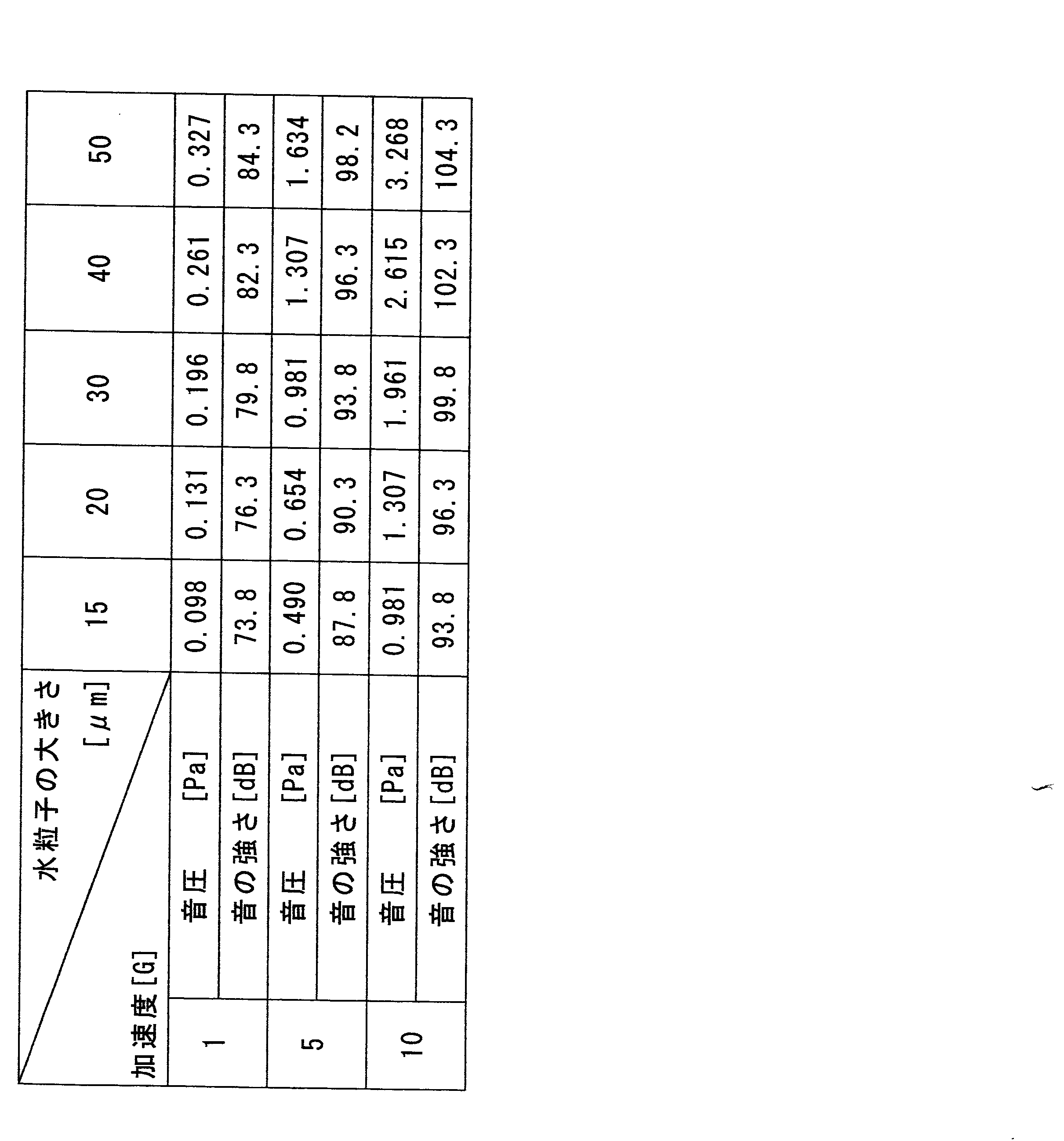
なお、音圧[Pa]と音の強さ[dB]の関係は下の式4で表される。
L=20log(P/P0) ……(式4)
ここで、Lは音の強さ(または音圧レベル)[dB]、Pは音圧[Pa]、P0は人間に聞こえる最小音圧[Pa]であって、P0=2×10⁻⁵[Pa]=2×10⁻⁹[N/cm2]である。
L=20log(P/P0) ……(式4)
ここで、Lは音の強さ(または音圧レベル)[dB]、Pは音圧[Pa]、P0は人間に聞こえる最小音圧[Pa]であって、P0=2×10⁻⁵[Pa]=2×10⁻⁹[N/cm2]である。
さらに、単位面積当たりに通過するエネルギーは下の式5で得られる。
[単位面積当たりに通過するエネルギー]=[音圧]2/([空気密度]×[音速])
……(式5)
[単位面積当たりに通過するエネルギー]=[音圧]2/([空気密度]×[音速])
……(式5)
そこで、図5~図8の着氷条件下で、過冷却水を氷にするために必要な音波の単位面積当たりに通過するエネルギー[W/m2]を算出した。図5~図8の斜線部分が、FAR25(米国連邦航空局(FAA)の米国連邦航空規則(FAR)Part25)において、着氷条件として規定されている。図5および図6に示す着氷条件は、雲が広い領域(20マイル)に拡がっている場合であり、下の表では着氷領域「連続」と表示している。図7および図8に示す着氷条件は、雲のある領域(3マイル)は狭いが、雲中の水滴の量が多い場合であり、下の表では着氷領域「間欠」と表示している。図5および図7は、水滴含有量[gr/m3]と水滴径[μm]の関係を示すグラフであり、図6および図8は、大気温度[゜F]と気圧高度[1000Ft]の関係を示すグラフである。
図5~図8の着氷条件はモデルではあるが、着氷する高度は通常20[kft]以下で、高くても30[kft]以下であることを示している。したがって、航空機10の飛行速度は、この高度では、音速より遅いと考えられるため、本発明を用いることによって、過冷却水が水滴のまま航空機に接触しないように制御することは可能と判断する。
過冷却水が1Gの加速度を得る際の所要音圧[Pa]、音の強さ[dB]、単位面積当たりに通過するエネルギー[W/m2]は下の表の通りとなった。
過冷却水が5Gの加速度を得る際の所要音圧[Pa]、音の強さ[dB]、単位面積当たりに通過するエネルギー[W/m2]は下の表の通りとなった。

過冷却水が10Gの加速度を得る際の所要音圧[Pa]、音の強さ[dB]、単位面積当たりに通過するエネルギー[W/m2]は下の表の通りとなった。

上記表より、過冷却水が10Gの加速度を得るのに必要な音圧は、約0.9~3.3[Pa]であり、音の強さは、約93~105[dB]であり、単位面積当たりに通過するエネルギーは、約0.2~7.5[W/m2]であるから、減衰を考慮し、音波発生装置1は、目標とする機体よりも前方の領域で約0.9~3.3[Pa]の音波を有する圧力波を発生するとよい。なお、過冷却水が5Gの加速度を得るのに必要な音圧は、約0.4~1.7[Pa]であり、音の強さは、約87~99[dB]であり、単位面積当たりに通過するエネルギーは、約0.05~1.9[W/m2]である。
以上より、航空機10の前方に音波発生装置1が配置されることで、図9に示すように、音波発生装置1が前方の飛行環境、特に過冷却水30に向けて音波20を発射する。そして、本発明の音波発生装置1によれば、音波の伝搬した広い領域の過冷却水を氷に変えることができる。したがって、過冷却水30は氷40に変化し、飛行環境から過冷却水30が消滅する。そのため、図10に示すように、すでに氷40となった飛行環境に航空機が飛行していっても、航空機10に着氷することはない。図9は、飛行中の航空機10と飛行環境中の過冷却水30を示す説明図であり、図10は、飛行中の航空機10と飛行環境中の氷40を示す説明図である。
次に、本発明の音波発生装置1の変形例である音波発生装置21について、図4を参照して説明する。図4の音波発生装置21は、防氷装置の一例であり、複数の音波発生源22が航空機10の主翼11の外板23の内側に設けられたものである。音波発生装置21は、機体の外板23を活用して外板23から直接音波を出力する。音波発生装置21は、図1に示す航空機10の前方部の音波発生装置1と同位置に設置され、機体よりも前方に音波を放射する。ここで、音波は圧力波の一例である。
本変形例において、音波発生装置21は音波が放射される部分を複数に分けておく。そして、位相制御によって、特定の方向に音波の圧力が強くなるように音波を放射できる。
なお、本発明の音波発生装置1,21をヘリコプターなどの回転翼を有する航空機に設置する場合、音波発生装置1,21は、例えば機体の胴体前方部や脚部に設置される。
[第2実施形態]
次に、本発明の第2実施形態に係る防氷方法について説明する。
上記実施例では、航空機10が防氷装置を装備して、波を前方に放射する場合について説明したが、本発明はこの例に限定されない。例えば、着氷を防止したい航空機10とは別に防氷装置を備えた施設を地上に設けてもよい。しかし、上記の航空機10に搭載する防氷装置と同じ装置を地上に装備するとした場合、カバーすべき領域が広すぎるため、現実的ではない。
次に、本発明の第2実施形態に係る防氷方法について説明する。
上記実施例では、航空機10が防氷装置を装備して、波を前方に放射する場合について説明したが、本発明はこの例に限定されない。例えば、着氷を防止したい航空機10とは別に防氷装置を備えた施設を地上に設けてもよい。しかし、上記の航空機10に搭載する防氷装置と同じ装置を地上に装備するとした場合、カバーすべき領域が広すぎるため、現実的ではない。
そこで、緊急用地上設備からロケットを発射し、過冷却水を含む雲の高度までロケットを到達させた後、火薬の爆発により音波(圧力波)を放射する。これにより、過冷却水として存在する水滴を、航空機に接触する前に広範囲にわたって氷の状態に変え、空港周辺上空の着氷環境を一時的に改善することができる。その結果、航空機への着氷を防止でき、安全な着陸をサポートできる。
但し、本装置は近くに航空機がいる場合には火薬の量によっては圧力波が強すぎて航空機を破損させる可能性があり使用できない。そこで、火薬の爆発による音圧で過冷却水が氷になるのに必要なエネルギーが常識的な量の火薬で発生できるかを試算した。
Wikipediaの「火薬」には鋳造トリニトロトルエン(TNT)の記述があり、下記の値が示されていた。(別資料で、TNT火薬について、1kgで約4.2×10⁶[J]の値があったが、ここに示すエネルギーの方が小さく安全側のため、この値を用いて検討する。
半径:10[cm]、
重量:6.49[kg]、
爆発熱:約1.17×10⁷[J]、
反応時間:14.7nsec、
エネルギーの発生速度:1.16×10¹²[J/sec](=[W])
半径:10[cm]、
重量:6.49[kg]、
爆発熱:約1.17×10⁷[J]、
反応時間:14.7nsec、
エネルギーの発生速度:1.16×10¹²[J/sec](=[W])
以下、雲の広がりが20[mile]で、2[W/m2]を発生するために必要な火薬の重量を算出する。
20[mile]=32,186.2[m]
火薬の爆発で圧力波が球状に広がるとして、必要な時間当たりのエネルギーは
4π×32,186.22×2=2.604×10¹⁰[W]
効率を10[%]しかないとしても必要な火薬の量は、
6.49×(2.604×1010)/(1.16×1012)/0.1=1.457[kg]
となる。
このとき、火薬の半径は、
10×{1.457/6.49}1/3=6.1[cm]
である。
以上より、大きさの面からは実施可能であることが判る。
20[mile]=32,186.2[m]
火薬の爆発で圧力波が球状に広がるとして、必要な時間当たりのエネルギーは
4π×32,186.22×2=2.604×10¹⁰[W]
効率を10[%]しかないとしても必要な火薬の量は、
6.49×(2.604×1010)/(1.16×1012)/0.1=1.457[kg]
となる。
このとき、火薬の半径は、
10×{1.457/6.49}1/3=6.1[cm]
である。
以上より、大きさの面からは実施可能であることが判る。
但し、別途Wikipediaの「爆風」に構造物の損傷が生じる圧力が示されており、この圧力は過冷却水を氷に変えるのに必要な圧力の約1000倍以上に達する。これからこの条件に合致する距離を算出すると、20[mile]の範囲の過冷却水を氷に変える条件では、構造物の損傷が生じる圧力の範囲は、約1[km]となった。20[mile]の位置で、過冷却水を氷に変えるのに必要な圧力以上の圧力が発生する場合には、構造物の損傷が生じる圧力の範囲は更に広くなる。
このことから、火薬を用いる防氷方法を実施する場合には、発生する圧力波が安全な大きさとなるよう火薬を十分高い高度に上げてから実施することが望ましい。また、上記の試算では、火薬の量を安全側に検討するために、圧力に変わる火薬のエネルギー効率を10[%]としており、実際に爆風による安全面からは火薬の量を試験で確認し、減らす必要がある。
以上、本発明は従来の方法と全く異なり、着氷の原因である過冷却水自体を環境中から消滅させるものである。本発明の防氷装置、防氷方法は、比較的安く、軽量でかつ他の方法に比べてエネルギーが小さい。また、第1の実施形態に係る音波発生装置1は、装着位置が着氷を防ぎたい位置にある必要がないという利点がある。なお、音波発生装置1を装備している航空機10が防除氷装置を装備していない航空機に対して前を飛行することにより安全な着陸をサポートすることもできる。
1,21 音波発生装置
2,22 音波発生源
10 航空機
11 主翼
23 外板
2,22 音波発生源
10 航空機
11 主翼
23 外板
Claims (6)
- 航空機の進行方向に存在する空気中に浮遊し過冷却状態にある水滴に向けて圧力波を出力し、前記圧力波によって前記水滴を氷に変化させる防氷装置。
- 航空機の進行方向に存在する空気中に浮遊し過冷却状態にある水滴に向けて機体よりも前方の所定位置において0.9~3.3[Pa]の範囲にある圧力波を発生させる防氷装置。
- 請求項1または2に記載の防氷装置が設けられた翼。
- 請求項1または2に記載の防氷装置が設けられた航空機。
- 航空機の進行方向に存在する空気中に浮遊し過冷却状態にある水滴に向けて圧力波を出力し、前記圧力波によって前記水滴を氷に変化させる防氷方法。
- 前記圧力波の出力は火薬の爆発によって実現される請求項5に記載の防氷方法。
Priority Applications (1)
| Application Number | Priority Date | Filing Date | Title |
|---|---|---|---|
| US13/824,639 US20130181093A1 (en) | 2011-01-20 | 2011-12-26 | Anti-icing system, wing, aircraft, and anti-icing method |
Applications Claiming Priority (2)
| Application Number | Priority Date | Filing Date | Title |
|---|---|---|---|
| JP2011010093A JP2012148716A (ja) | 2011-01-20 | 2011-01-20 | 防氷装置、翼、航空機および防氷方法 |
| JP2011-010093 | 2011-01-20 |
Publications (1)
| Publication Number | Publication Date |
|---|---|
| WO2012098809A1 true WO2012098809A1 (ja) | 2012-07-26 |
Family
ID=46515446
Family Applications (1)
| Application Number | Title | Priority Date | Filing Date |
|---|---|---|---|
| PCT/JP2011/080044 Ceased WO2012098809A1 (ja) | 2011-01-20 | 2011-12-26 | 防氷装置、翼、航空機および防氷方法 |
Country Status (3)
| Country | Link |
|---|---|
| US (1) | US20130181093A1 (ja) |
| JP (1) | JP2012148716A (ja) |
| WO (1) | WO2012098809A1 (ja) |
Families Citing this family (5)
| Publication number | Priority date | Publication date | Assignee | Title |
|---|---|---|---|---|
| IT201600098196A1 (it) | 2016-09-30 | 2018-03-30 | Torino Politecnico | Aeromobile dotato di sistema antighiaccio strutturalmente integrato. |
| US10870491B2 (en) * | 2017-07-20 | 2020-12-22 | The Boeing Company | Eductor driven anti-ice system |
| CN111452951B (zh) * | 2020-04-14 | 2022-01-14 | 山东大学 | 一种机翼除冰装置及包括该除冰装置的机翼 |
| CN113415428B (zh) * | 2021-08-20 | 2021-11-02 | 中国空气动力研究与发展中心低速空气动力研究所 | 一种用于除冰的热发泡式冲击力发生器 |
| CN113962028B (zh) * | 2021-11-12 | 2024-04-30 | 北京航空航天大学 | 一种考虑结冰影响的无人机气动导数辨识方法 |
Citations (5)
| Publication number | Priority date | Publication date | Assignee | Title |
|---|---|---|---|---|
| JPS61160395A (ja) * | 1985-01-09 | 1986-07-21 | 財団法人日本航空機開発協会 | 航空機の防氷装置 |
| JPH03251668A (ja) * | 1990-02-28 | 1991-11-11 | Nkk Corp | 人工造雪方法およびその装置 |
| JPH03295797A (ja) * | 1990-04-12 | 1991-12-26 | Mitsubishi Heavy Ind Ltd | 鳥衝突防止装置 |
| JP2010504250A (ja) * | 2006-09-25 | 2010-02-12 | ローズマウント・エアロスペース・インコーポレーテッド | 氷粒の検出 |
| WO2010137596A1 (ja) * | 2009-05-26 | 2010-12-02 | 国立大学法人 千葉大学 | 移動体制御装置及び移動体制御装置を搭載した移動体 |
Family Cites Families (3)
| Publication number | Priority date | Publication date | Assignee | Title |
|---|---|---|---|---|
| US2480275A (en) * | 1947-10-04 | 1949-08-30 | Straten | Method of crystallizing supercooled water droplets |
| US5817969A (en) * | 1994-08-26 | 1998-10-06 | Oerlikon Contraves Pyrotec Ag | Spin-stabilized projectile with payload |
| US8424439B2 (en) * | 2010-09-03 | 2013-04-23 | Raytheon Company | Systems and methods for launching munitions |
-
2011
- 2011-01-20 JP JP2011010093A patent/JP2012148716A/ja active Pending
- 2011-12-26 WO PCT/JP2011/080044 patent/WO2012098809A1/ja not_active Ceased
- 2011-12-26 US US13/824,639 patent/US20130181093A1/en not_active Abandoned
Patent Citations (5)
| Publication number | Priority date | Publication date | Assignee | Title |
|---|---|---|---|---|
| JPS61160395A (ja) * | 1985-01-09 | 1986-07-21 | 財団法人日本航空機開発協会 | 航空機の防氷装置 |
| JPH03251668A (ja) * | 1990-02-28 | 1991-11-11 | Nkk Corp | 人工造雪方法およびその装置 |
| JPH03295797A (ja) * | 1990-04-12 | 1991-12-26 | Mitsubishi Heavy Ind Ltd | 鳥衝突防止装置 |
| JP2010504250A (ja) * | 2006-09-25 | 2010-02-12 | ローズマウント・エアロスペース・インコーポレーテッド | 氷粒の検出 |
| WO2010137596A1 (ja) * | 2009-05-26 | 2010-12-02 | 国立大学法人 千葉大学 | 移動体制御装置及び移動体制御装置を搭載した移動体 |
Also Published As
| Publication number | Publication date |
|---|---|
| JP2012148716A (ja) | 2012-08-09 |
| US20130181093A1 (en) | 2013-07-18 |
Similar Documents
| Publication | Publication Date | Title |
|---|---|---|
| ES2593780T3 (es) | Aeronave camuflada | |
| WO2012098809A1 (ja) | 防氷装置、翼、航空機および防氷方法 | |
| WO2010023253A1 (en) | A bird collision avoidance system | |
| US8827211B2 (en) | Laser-based flow modification to remotely control air vehicle flight path | |
| RU2012131131A (ru) | Сверхскоростное воздушное судно и соответствующий способ воздушного передвижения | |
| CN106379552B (zh) | 基于系留气球的小型无人机收放方法 | |
| RU2768999C1 (ru) | Береговой комплекс авиационно-ракетный многоразовый автономный | |
| US3709446A (en) | Sonic boom reduction | |
| Tatić et al. | Analysis of noise level generated by helicopters with various numbers of blades in the main rotor | |
| US3428273A (en) | Aircraft launching | |
| RU2724026C1 (ru) | Способ снижения влияния обледенения на аэродинамическую поверхность | |
| RU2604951C1 (ru) | Самолет короткого взлета и посадки | |
| RU2532591C1 (ru) | Мишенный комплекс с малоразмерными радиоуправляемыми мишенями | |
| Han | Experimental investigations on the propeller performances of Unmanned-Aerial-Vehicles | |
| RU2228883C2 (ru) | Способ уменьшения обледенения летательных аппаратов | |
| Lawson | Electrically powered ice protection systems for MALE UAVs-Requirements and integration challenges | |
| RU2484279C1 (ru) | Способ повышения эффективности торможения самолета на пробеге и повышения безопасности при взлете и посадке и устройство для его реализации | |
| Anderson et al. | Supersonic Flight | |
| US20140263830A1 (en) | Launch lightning risk mitigation system and method | |
| US20170363001A1 (en) | Aircraft engine shield | |
| ES2803356T3 (es) | Dispositivo de atenuación de la estela de un vórtice | |
| Withington | Bad vibrations | |
| RU2703658C1 (ru) | Беспилотный самолёт | |
| Chorlton | The Javelin | |
| BG4580U1 (bg) | Прехващач на дронове с витлов движител и генератор на маркс |
Legal Events
| Date | Code | Title | Description |
|---|---|---|---|
| 121 | Ep: the epo has been informed by wipo that ep was designated in this application |
Ref document number: 11856494 Country of ref document: EP Kind code of ref document: A1 |
|
| WWE | Wipo information: entry into national phase |
Ref document number: 13824639 Country of ref document: US |
|
| NENP | Non-entry into the national phase |
Ref country code: DE |
|
| 122 | Ep: pct application non-entry in european phase |
Ref document number: 11856494 Country of ref document: EP Kind code of ref document: A1 |