WO2012098790A1 - 画像処理装置及び画像処理方法 - Google Patents
画像処理装置及び画像処理方法 Download PDFInfo
- Publication number
- WO2012098790A1 WO2012098790A1 PCT/JP2011/079031 JP2011079031W WO2012098790A1 WO 2012098790 A1 WO2012098790 A1 WO 2012098790A1 JP 2011079031 W JP2011079031 W JP 2011079031W WO 2012098790 A1 WO2012098790 A1 WO 2012098790A1
- Authority
- WO
- WIPO (PCT)
- Prior art keywords
- line
- unit
- determination
- deblocking filter
- image
- Prior art date
Links
Images


Classifications
-
- H—ELECTRICITY
- H04—ELECTRIC COMMUNICATION TECHNIQUE
- H04N—PICTORIAL COMMUNICATION, e.g. TELEVISION
- H04N19/00—Methods or arrangements for coding, decoding, compressing or decompressing digital video signals
- H04N19/10—Methods or arrangements for coding, decoding, compressing or decompressing digital video signals using adaptive coding
- H04N19/102—Methods or arrangements for coding, decoding, compressing or decompressing digital video signals using adaptive coding characterised by the element, parameter or selection affected or controlled by the adaptive coding
- H04N19/117—Filters, e.g. for pre-processing or post-processing
-
- H—ELECTRICITY
- H04—ELECTRIC COMMUNICATION TECHNIQUE
- H04N—PICTORIAL COMMUNICATION, e.g. TELEVISION
- H04N19/00—Methods or arrangements for coding, decoding, compressing or decompressing digital video signals
- H04N19/10—Methods or arrangements for coding, decoding, compressing or decompressing digital video signals using adaptive coding
- H04N19/134—Methods or arrangements for coding, decoding, compressing or decompressing digital video signals using adaptive coding characterised by the element, parameter or criterion affecting or controlling the adaptive coding
- H04N19/136—Incoming video signal characteristics or properties
- H04N19/14—Coding unit complexity, e.g. amount of activity or edge presence estimation
-
- H—ELECTRICITY
- H04—ELECTRIC COMMUNICATION TECHNIQUE
- H04N—PICTORIAL COMMUNICATION, e.g. TELEVISION
- H04N19/00—Methods or arrangements for coding, decoding, compressing or decompressing digital video signals
- H04N19/10—Methods or arrangements for coding, decoding, compressing or decompressing digital video signals using adaptive coding
- H04N19/169—Methods or arrangements for coding, decoding, compressing or decompressing digital video signals using adaptive coding characterised by the coding unit, i.e. the structural portion or semantic portion of the video signal being the object or the subject of the adaptive coding
- H04N19/17—Methods or arrangements for coding, decoding, compressing or decompressing digital video signals using adaptive coding characterised by the coding unit, i.e. the structural portion or semantic portion of the video signal being the object or the subject of the adaptive coding the unit being an image region, e.g. an object
- H04N19/176—Methods or arrangements for coding, decoding, compressing or decompressing digital video signals using adaptive coding characterised by the coding unit, i.e. the structural portion or semantic portion of the video signal being the object or the subject of the adaptive coding the unit being an image region, e.g. an object the region being a block, e.g. a macroblock
-
- H—ELECTRICITY
- H04—ELECTRIC COMMUNICATION TECHNIQUE
- H04N—PICTORIAL COMMUNICATION, e.g. TELEVISION
- H04N19/00—Methods or arrangements for coding, decoding, compressing or decompressing digital video signals
- H04N19/60—Methods or arrangements for coding, decoding, compressing or decompressing digital video signals using transform coding
- H04N19/61—Methods or arrangements for coding, decoding, compressing or decompressing digital video signals using transform coding in combination with predictive coding
-
- H—ELECTRICITY
- H04—ELECTRIC COMMUNICATION TECHNIQUE
- H04N—PICTORIAL COMMUNICATION, e.g. TELEVISION
- H04N19/00—Methods or arrangements for coding, decoding, compressing or decompressing digital video signals
- H04N19/80—Details of filtering operations specially adapted for video compression, e.g. for pixel interpolation
-
- H—ELECTRICITY
- H04—ELECTRIC COMMUNICATION TECHNIQUE
- H04N—PICTORIAL COMMUNICATION, e.g. TELEVISION
- H04N19/00—Methods or arrangements for coding, decoding, compressing or decompressing digital video signals
- H04N19/85—Methods or arrangements for coding, decoding, compressing or decompressing digital video signals using pre-processing or post-processing specially adapted for video compression
- H04N19/86—Methods or arrangements for coding, decoding, compressing or decompressing digital video signals using pre-processing or post-processing specially adapted for video compression involving reduction of coding artifacts, e.g. of blockiness
Definitions
- the present disclosure relates to an image processing apparatus and an image processing method.
- H. is one of the standard specifications for image coding.
- a deblocking filter is applied to a block boundary for each block of 4 ⁇ 4 pixels, for example, in order to suppress deterioration in image quality due to block distortion that occurs during image coding.
- the amount of processing required for this deblocking filter is enormous, and for example, it is said that it may occupy 50% of the total amount of processing when decoding an image.
- JCTVC-A119 In the standardization work of HEVC (High Efficiency Video Coding), the next-generation image encoding method, a deblock filter is applied to each block of 8 ⁇ 8 pixels or more in JCTVC-A119 (see Non-Patent Document 1 below). It has been proposed to do. In the method proposed in JCTVC-A119, the block size of the minimum unit to which the deblocking filter is applied is expanded. Even in this method, H.C. Similar to H.264 / AVC, the necessity of applying the deblocking filter is determined in units of blocks.
- JCT-VC Video coding technology proposal by Tandberg, Nokia, and Ericsson
- JCT-VC Documents of the team of the int on Video Coding
- image quality degradation due to block distortion does not necessarily appear uniformly in the block. That is, there is a possibility that the image quality of a part of the block determined to be applied with the deblocking filter is already good. In addition, there is a possibility that the image quality of a part of the block that is determined not to apply the deblocking filter actually deteriorates. If a deblocking filter is applied to a portion having good image quality, the image quality may be impaired. Further, the image quality is not improved unless the deblocking filter is applied to the portion having the degraded image quality.
- a decoding unit that decodes an encoded stream to generate an image, and a line that is orthogonal to the boundary in adjacent blocks that are adjacent to each other across the boundary in the image generated by the decoding unit.
- An image processing apparatus comprising: a line determination unit that determines whether to apply a deblocking filter to each line; and a filtering unit that applies a deblocking filter to each line determined to be applied by the line determination unit Is provided.
- the image processing apparatus can typically be realized as an image decoding apparatus that decodes an image.
- an image is generated by decoding an encoded stream, and for each line orthogonal to the boundary in adjacent blocks that are adjacent to each other with the boundary in the generated image.
- An image processing method including determining whether to apply a deblocking filter and applying the deblocking filter to each line determined to apply the deblocking filter is provided.
- a deblocking filter is provided for each line orthogonal to the boundary in adjacent blocks that are adjacent to each other across the boundary in the locally decoded image when the encoding target image is encoded.
- a line determination unit that determines whether to apply a deblocking filter, a filtering unit that applies a deblocking filter to each line determined to apply a deblocking filter by the line determination unit, and an image filtered by the filtering unit.
- an image processing apparatus including an encoding unit that encodes the encoding target image.
- the image processing apparatus can typically be realized as an image encoding apparatus that encodes an image.
- a deblocking filter is provided for each line orthogonal to the boundary in adjacent blocks that are adjacent to each other across the boundary in the locally decoded image when the encoding target image is encoded. Applying the deblocking filter to each line determined to apply the deblocking filter, and encoding the encoding target image using the filtered image. , An image processing method is provided.
- the image processing apparatus and the image processing method according to the present disclosure can more appropriately determine the range to which the deblocking filter is applied.
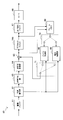
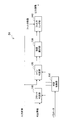
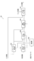
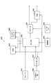
- FIG. 1 is a block diagram illustrating an example of a configuration of an image encoding device 10 according to an embodiment.
- an image encoding device 10 includes an A / D (Analogue to Digital) conversion unit 11, a rearrangement buffer 12, a subtraction unit 13, an orthogonal transformation unit 14, a quantization unit 15, a lossless encoding unit 16, Accumulation buffer 17, rate control unit 18, inverse quantization unit 21, inverse orthogonal transform unit 22, addition unit 23, deblock filter 24a, frame memory 25, selector 26, intra prediction unit 30, motion search unit 40, and mode selection Part 50 is provided.
- a / D Analogue to Digital
- the A / D converter 11 converts an image signal input in an analog format into image data in a digital format, and outputs a series of digital image data to the rearrangement buffer 12.
- the rearrangement buffer 12 rearranges the images included in the series of image data input from the A / D conversion unit 11.
- the rearrangement buffer 12 rearranges the images according to the GOP (Group of Pictures) structure related to the encoding process, and then outputs the rearranged image data to the subtraction unit 13, the intra prediction unit 30, and the motion search unit 40. To do.
- GOP Group of Pictures
- the subtraction unit 13 is supplied with image data input from the rearrangement buffer 12 and predicted image data selected by the mode selection unit 50 described later.
- the subtraction unit 13 calculates prediction error data that is a difference between the image data input from the rearrangement buffer 12 and the prediction image data input from the mode selection unit 50, and sends the calculated prediction error data to the orthogonal transformation unit 14. Output.
- the orthogonal transform unit 14 performs orthogonal transform on the prediction error data input from the subtraction unit 13.
- the orthogonal transformation performed by the orthogonal transformation part 14 may be discrete cosine transformation (Discrete Cosine Transform: DCT) or Karoonen-Labe transformation, for example.
- the orthogonal transform unit 14 outputs transform coefficient data acquired by the orthogonal transform process to the quantization unit 15.
- the quantization unit 15 is supplied with transform coefficient data input from the orthogonal transform unit 14 and a rate control signal from the rate control unit 18 described later.
- the quantizing unit 15 quantizes the transform coefficient data and outputs the quantized transform coefficient data (hereinafter referred to as quantized data) to the lossless encoding unit 16 and the inverse quantization unit 21.
- the quantization unit 15 changes the bit rate of the quantized data input to the lossless encoding unit 16 by switching the quantization parameter (quantization scale) based on the rate control signal from the rate control unit 18.
- the lossless encoding unit 16 includes quantized data input from the quantization unit 15, and intra prediction or inter prediction generated by the intra prediction unit 30 or the motion search unit 40 described later and selected by the mode selection unit 50.
- Information about is provided.
- the information regarding intra prediction may include, for example, prediction mode information indicating an optimal intra prediction mode for each block.
- the information regarding inter prediction may include, for example, prediction mode information for motion vector prediction for each block, differential motion vector information, reference image information, and the like.
- the lossless encoding unit 16 generates an encoded stream by performing lossless encoding processing on the quantized data.
- the lossless encoding by the lossless encoding unit 16 may be variable length encoding or arithmetic encoding, for example.
- the lossless encoding unit 16 multiplexes the above-described information related to intra prediction or information related to inter prediction in a header (for example, a block header or a slice header) of an encoded stream. Then, the lossless encoding unit 16 outputs the generated encoded stream to the accumulation buffer 17.
- the accumulation buffer 17 temporarily accumulates the encoded stream input from the lossless encoding unit 16.
- the accumulation buffer 17 outputs the accumulated encoded stream at a rate corresponding to the bandwidth of the transmission path (or the output line from the image encoding device 10).
- the rate control unit 18 monitors the free capacity of the accumulation buffer 17. Then, the rate control unit 18 generates a rate control signal according to the free capacity of the accumulation buffer 17 and outputs the generated rate control signal to the quantization unit 15. For example, the rate control unit 18 generates a rate control signal for reducing the bit rate of the quantized data when the free capacity of the storage buffer 17 is small. For example, when the free capacity of the accumulation buffer 17 is sufficiently large, the rate control unit 18 generates a rate control signal for increasing the bit rate of the quantized data.
- the inverse quantization unit 21 performs an inverse quantization process on the quantized data input from the quantization unit 15. Then, the inverse quantization unit 21 outputs transform coefficient data acquired by the inverse quantization process to the inverse orthogonal transform unit 22.
- the inverse orthogonal transform unit 22 restores the prediction error data by performing an inverse orthogonal transform process on the transform coefficient data input from the inverse quantization unit 21. Then, the inverse orthogonal transform unit 22 outputs the restored prediction error data to the addition unit 23.
- the addition unit 23 generates decoded image data by adding the restored prediction error data input from the inverse orthogonal transform unit 22 and the predicted image data input from the mode selection unit 50. Then, the adder 23 outputs the generated decoded image data to the deblock filter 24 a and the frame memory 25.
- the deblocking filter 24a performs a filtering process for reducing block distortion that occurs during image encoding. More specifically, the deblocking filter 24 a determines whether or not filtering is necessary for each block boundary in the decoded image data input from the adding unit 23. Then, the deblocking filter 24a applies the deblocking filter to the line determined to be applied with the filter. When the block boundary is a vertical boundary, the line corresponds to a row orthogonal to the vertical boundary. When the block boundary is a horizontal boundary, the line corresponds to a column orthogonal to the horizontal boundary.
- the deblocking filter 24a In addition to the decoded image data from the adding unit 23, information (for example, mode information, transform coefficient information, and motion vector information) used for determining whether filtering is necessary is input to the deblocking filter 24a. Thereafter, the deblocking filter 24 a outputs the decoded image data after filtering from which block distortion has been removed to the frame memory 25. The processing by the deblocking filter 24a will be described in detail later.
- the frame memory 25 stores the decoded image data input from the adder 23 and the decoded image data after filtering input from the deblocking filter 24a.
- the selector 26 reads out the decoded image data before filtering used for intra prediction from the frame memory 25 and supplies the read decoded image data to the intra prediction unit 30 as reference image data. Further, the selector 26 reads out the filtered decoded image data used for inter prediction from the frame memory 25 and supplies the read decoded image data to the motion search unit 40 as reference image data.
- the intra prediction unit 30 performs an intra prediction process in each intra prediction mode based on the image data to be encoded input from the rearrangement buffer 12 and the decoded image data supplied via the selector 26. For example, the intra prediction unit 30 evaluates the prediction result in each intra prediction mode using a predetermined cost function. Then, the intra prediction unit 30 selects an intra prediction mode in which the cost function value is minimum, that is, an intra prediction mode in which the compression rate is the highest as the optimal intra prediction mode. Further, the intra prediction unit 30 outputs information related to intra prediction including prediction mode information representing the optimal intra prediction mode, predicted image data, and a cost function value to the mode selection unit 50.
- the motion search unit 40 performs inter prediction processing (interframe prediction processing) based on the image data to be encoded input from the rearrangement buffer 12 and the decoded image data supplied via the selector 26. For example, the motion search unit 40 evaluates the prediction result in each prediction mode using a predetermined cost function. Next, the motion search unit 40 selects a prediction mode with the smallest cost function value, that is, a prediction mode with the highest compression rate, as the optimum prediction mode. Further, the motion search unit 40 generates predicted image data according to the optimal prediction mode. Then, the motion search unit 40 outputs information related to inter prediction including prediction mode information indicating the selected optimal prediction mode, predicted image data, and a cost function value to the mode selection unit 50.
- inter prediction processing interframe prediction processing
- the mode selection unit 50 compares the cost function value related to intra prediction input from the intra prediction unit 30 with the cost function value related to inter prediction input from the motion search unit 40. And the mode selection part 50 selects the prediction method with few cost function values among intra prediction and inter prediction.
- the mode selection unit 50 outputs information on the intra prediction to the lossless encoding unit 16 and outputs the predicted image data to the subtraction unit 13 and the addition unit 23.
- the mode selection unit 50 outputs the above-described information regarding inter prediction to the lossless encoding unit 16 and outputs the predicted image data to the subtraction unit 13 and the addition unit 23.
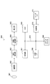
- FIG. 2 is a block diagram illustrating an example of the configuration of the image decoding device 60 according to an embodiment.
- the image decoding device 60 includes an accumulation buffer 61, a lossless decoding unit 62, an inverse quantization unit 63, an inverse orthogonal transform unit 64, an addition unit 65, a deblock filter 24b, a rearrangement buffer 67, a D / A (Digital to Analogue) conversion unit 68, frame memory 69, selectors 70 and 71, intra prediction unit 80, and motion compensation unit 90 are provided.
- the accumulation buffer 61 temporarily accumulates the encoded stream input via the transmission path.
- the lossless decoding unit 62 decodes the encoded stream input from the accumulation buffer 61 according to the encoding method used at the time of encoding. In addition, the lossless decoding unit 62 decodes information multiplexed in the header area of the encoded stream.
- the information multiplexed in the header area of the encoded stream can include, for example, information related to intra prediction and information related to inter prediction in a block header.
- the lossless decoding unit 62 outputs information related to intra prediction to the intra prediction unit 80. Further, the lossless decoding unit 62 outputs information related to inter prediction to the motion compensation unit 90.
- the inverse quantization unit 63 performs inverse quantization on the quantized data decoded by the lossless decoding unit 62.
- the inverse orthogonal transform unit 64 generates prediction error data by performing inverse orthogonal transform on the transform coefficient data input from the inverse quantization unit 63 according to the orthogonal transform method used at the time of encoding. Then, the inverse orthogonal transform unit 64 outputs the generated prediction error data to the addition unit 65.
- the addition unit 65 adds the prediction error data input from the inverse orthogonal transform unit 64 and the prediction image data input from the selector 71 to generate decoded image data. Then, the addition unit 65 outputs the generated decoded image data to the deblock filter 24b and the frame memory 69.
- the deblocking filter 24b performs a filtering process for reducing block distortion appearing in the decoded image. More specifically, the deblocking filter 24b determines whether or not filtering is necessary for each block boundary in the decoded image data input from the adding unit 65. Then, the deblocking filter 24a applies the deblocking filter to the line determined to be applied with the filter. In addition to the decoded image data from the adding unit 65, information used for determining whether filtering is necessary is input to the deblocking filter 24b. Thereafter, the deblocking filter 24 b outputs the decoded image data after filtering from which block distortion has been removed to the rearrangement buffer 67 and the frame memory 69. The processing by the deblocking filter 24b will be described in detail later.
- the rearrangement buffer 67 generates a series of image data in time series by rearranging the images input from the deblocking filter 24b. Then, the rearrangement buffer 67 outputs the generated image data to the D / A conversion unit 68.
- the D / A converter 68 converts the digital image data input from the rearrangement buffer 67 into an analog image signal. Then, the D / A conversion unit 68 displays an image by outputting an analog image signal to a display (not shown) connected to the image decoding device 60, for example.
- the frame memory 69 stores the decoded image data before filtering input from the adding unit 65 and the decoded image data after filtering input from the deblocking filter 24b.
- the selector 70 switches the output destination of the image data from the frame memory 69 between the intra prediction unit 80 and the motion compensation unit 90 for each block in the image according to the mode information acquired by the lossless decoding unit 62. .
- the selector 70 outputs the decoded image data before filtering supplied from the frame memory 69 to the intra prediction unit 80 as reference image data.
- the selector 70 outputs the decoded image data after filtering supplied from the frame memory 69 to the motion compensation unit 90 as reference image data.
- the selector 71 sets the output source of the predicted image data to be supplied to the adding unit 65 for each block in the image according to the mode information acquired by the lossless decoding unit 62 between the intra prediction unit 80 and the motion compensation unit 90. Switch between. For example, the selector 71 supplies the prediction image data output from the intra prediction unit 80 to the adding unit 65 when the intra prediction mode is designated. The selector 71 supplies the predicted image data output from the motion compensation unit 90 to the adding unit 65 when the inter prediction mode is designated.
- the intra prediction unit 80 performs in-screen prediction of pixel values based on information related to intra prediction input from the lossless decoding unit 62 and reference image data from the frame memory 69, and generates predicted image data. Then, the intra prediction unit 80 outputs the generated predicted image data to the selector 71.
- the motion compensation unit 90 performs motion compensation processing based on the inter prediction information input from the lossless decoding unit 62 and the reference image data from the frame memory 69, and generates predicted image data. Then, the motion compensation unit 90 outputs the generated predicted image data to the selector 71.
- the processing by the deblocking filter in the existing image coding scheme such as H.264 / AVC or HEVC includes two types of processing: filtering necessity determination processing and filtering processing.
- filtering necessity determination processing and filtering processing.
- the filtering necessity determination process is a process for determining whether or not a deblocking filter should be applied for each block boundary in the input image.
- the block boundary includes a vertical boundary between adjacent blocks on the left and right and a horizontal boundary between adjacent blocks on the upper and lower sides.
- the block size of 8 ⁇ 8 pixels is the smallest processing unit.
- there are four 8 ⁇ 8 pixel blocks in a 16 ⁇ 16 pixel macroblock, one (left) vertical boundary and one (top) horizontal boundary per block, ie 4 + 4 Eight boundaries are subject to determination.
- the term “macroblock” includes a coding unit (CU) in the context of HEVC.
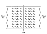
- FIG. 3 is an explanatory diagram illustrating an example of pixels in two blocks Ba and Bb that are adjacent to each other across a boundary.
- blocks adjacent to each other across the boundary are referred to as adjacent blocks.
- a vertical boundary will be described as an example, but it should be understood that the matters described here are equally applicable to a horizontal boundary.
- the pixels in the block Ba are indicated by the symbol p ij .
- i is a column index and j is a row index.
- the column index i is numbered 0, 1, 2, 3 in order from the column close to the vertical boundary (from right to left).
- the row index j is numbered 0, 1, 2,..., 7 from top to bottom. Note that the left half of the block Ba is omitted in the figure.
- the pixels in the block Bb are indicated by the symbol q kj .
- k is a column index and j is a row index.
- the column index k is numbered 0, 1, 2, 3 in order from the column close to the vertical boundary (from left to right).
- the right half of the block Bb is also omitted in the drawing.
- Whether the deblocking filter should be applied to the vertical boundary between the blocks Ba and Bb shown in FIG. 3 can be determined according to the following conditions:
- Condition A (A1) Block Ba or Bb is the intra prediction mode; (A2) Block Ba or Bb has a non-zero orthogonal transform coefficient; or (A3)
- the motion vector of the block Ba with Qpel (1/4 pixel) accuracy is (MVAx, MVAy), and the motion vector of the block Bb is (MVBx, MVBy).
- ⁇ in the condition B is an edge determination threshold value. The initial value of ⁇ is given according to the quantization parameter. Also, the value of ⁇ can be specified by the user with a parameter in the slice header.
- the second and fifth of each block The pixels in the 1st row (the top row is 0th) are referenced. Then, the deblocking filter is applied to the blocks on the left and right of the vertical boundary where it is determined that the deblocking filter should be applied according to the determination condition described above. Similarly, in the filtering necessity determination process for the horizontal boundary, the pixels in the second and fifth columns of each block (not shown in FIG. 4) are referred to. Then, the deblocking filter is applied to the blocks above and below the vertical boundary for which it is determined that the deblocking filter should be applied according to the above-described determination conditions.
- Luminance component filtering-Intensity selection Select filter intensity for each row (or for each column). A strong filter is selected if all of the following conditions C1 to C3 are satisfied, and a weak filter is selected if any one of the following conditions is not satisfied: (C1) d ⁇ ( ⁇ >> 2) (C2) (
- j is a row index for a vertical boundary and a column index for a horizontal boundary.
- ⁇ Clip ( ⁇ t C , t C , (13 (q 0j ⁇ p 0j ) +4 (q 1j ⁇ p 1j ) ⁇ 5 (q 2j ⁇ p 2j ) +16) >> 5))
- p 0j Clip 0-255 (p 0j + ⁇ )
- q 0j Clip 0-255 (q 0j - ⁇ )
- p 1j Clip 0-255 (p 1j + ⁇ / 2)
- q 1j Clip 0-255 (q 1j - ⁇ / 2)
- p 0j Clip 0-255 ((p 2j + 2p 1j + 2p 0j + 2q 0j + q 1j +4) >> 3)
- q 0j Clip 0-255 ((p 1j + 2p 0j + 2q 0j + 2q 1j + q 2j +4) >> 3)
- p 1j Clip 0-255 ((p 2j + p 1j + p 0j + q 0j +2) >> 2)
- q 1j Clip 0-255 ((p 0j + q 0j + q 1j + q 2j +2) >> 2)
- p 2j Clip 0-255 ((2p 3j + 3p 2j + p 1j + p 0j + q 0j +4) >> 3)
- q 2j Clip 0-255 ((p 0j + q 0j + 3q 2j + 2q 3j +4) >> 3)
- Clip (a, b, c) is a process of clipping the value c in the range of a ⁇ c ⁇ b
- Clip 0-255 (c) is a process of clipping the value c in the range of 0 ⁇ c ⁇ 255.
- ⁇ Clip ( ⁇ t C , t C , ((((q 0j ⁇ p 0j ) ⁇ 2) + p 1j ⁇ q 1j +4) >> 3))
- p 0j Clip 0-255 (p 0j + ⁇ )
- q 0j Clip 0-255 (q 0j - ⁇ )
- the filtering of the luminance component and the color difference component is performed for all the rows or columns of the blocks Ba and Bb (that is, for all integers j where 0 ⁇ j ⁇ 7). That is, as shown in FIG. 5, when it is determined that filtering is necessary for a certain vertical boundary, one or more pixel values of all lines L0 to L7 orthogonal to the vertical boundary are updated. Similarly, when it is determined that filtering is necessary for a certain horizontal boundary, one or more pixel values of all the lines L0 to L7 orthogonal to the horizontal boundary are updated.
- the necessity of filtering is determined for each boundary between two adjacent blocks in the image.
- a determination in units of blocks For certain boundaries, no determination is made that filtering is partially necessary. Therefore, even if image quality degradation due to block distortion appears only in some of the pixels in the block, it is only possible to choose between filtering the entire block or not filtering the entire block. .
- This is due to two adverse effects, such as a reduction in image quality due to the use of a useless deblocking filter on a portion having good image quality, and a loss of an opportunity to improve image quality due to the fact that the deblocking filter is not applied to a portion having deteriorated image quality. Is included. Therefore, in the two embodiments of the deblocking filter described below, in order to eliminate such an adverse effect, the range to which the deblocking filter should be applied is determined with a smaller granularity.
- the block determination unit 110 performs determination on the determination condition for the block unit as a process before the line determination unit 120 performs the line unit determination.
- the determination condition for each block is typically a condition based on at least one of a transform coefficient and a coding parameter of two adjacent blocks that sandwich the boundary.
- the transform coefficient may be, for example, an orthogonal transform coefficient.
- the encoding parameter may be, for example, one or both of the prediction mode and the motion vector.
- the determination condition for each block may be, for example, the determination condition A of the luminance component determination condition and the determination condition A1 of the color difference component in the existing method described above.
- the block determination unit 110 is supplied with determination information about adjacent blocks adjacent to each other across each boundary.
- the determination information supplied here includes, for example, mode information, conversion coefficient information, and motion vector information.
- the block determination part 110 determines whether the following conditions A are satisfy
- the block determination unit 110 causes the line determination unit 120 to further perform determination on a line basis for the boundary that satisfies the condition A. On the other hand, the block determination unit 110 causes the line determination unit 120 to skip line-by-line determination for a boundary that does not satisfy the condition A.
- the block determination unit 110 determines whether or not the following condition A1 is satisfied as the determination of the color difference component in units of blocks for each boundary: -Condition A1: For the color difference component in which the block Ba or Bb is in the intra prediction mode, the line determination unit 120 does not have to perform determination in units of lines. In this case, for the boundary satisfying the condition A1, the color difference components of all the lines of the boundary are filtered by the filtering unit 140. For the boundary that does not satisfy the condition A1, the color difference components of all the lines of the boundary are not filtered.
- the determination in units of blocks by the block determination unit 110 described here is merely an example. That is, a determination condition in block units different from the determination conditions described above may be used. For example, any one of the determination conditions A1 to A3 may be omitted, or another condition may be added. Further, for the color difference component, determination in units of lines as described below may be performed without being omitted.
- the line determination unit 120 determines, for each line orthogonal to each boundary, whether or not to apply the deblocking filter to two adjacent blocks adjacent to each other with the boundary interposed therebetween.
- d is a determination parameter
- ⁇ is the above-described edge determination threshold.
- I is an index of a line. If the size of each block is 8 ⁇ 8 pixels, i is an integer of 0 ⁇ i ⁇ 7.
- the line determination unit 120 calculates the value of the determination parameter d from only the reference pixel values belonging to the one line of the two adjacent blocks Ba and Bb according to the condition B ′. To do. Then, the line determination unit 120 compares the calculated determination parameter d with the determination threshold ( ⁇ >> 1). In this way, by referring to only the line when determining a certain line, it is possible to realize determination for each line with a relatively simple configuration in which each line is sequentially accessed.
- the line determination unit 120 causes, for example, filter strength selection by the strength selection unit 130 and filtering by the filtering unit 140 to be performed on a line that satisfies the condition B ′. On the other hand, the line determination unit 120 skips the filter strength selection by the strength selection unit 130 and the filtering by the filtering unit 140 for lines that do not satisfy the condition B ′.
- the intensity selection unit 130 selects the deblocking filter strength applied to each line by the filtering unit 140 for each line. More specifically, the strength selecting unit 130 selects the filter strength as follows for each line determined by the line determining unit 120 to apply the deblocking filter: -Intensity selection: Select filter strength for each line.
- a strong filter is selected if all of the following conditions C1 'to C3 are satisfied, and a weak filter is selected if any one of the following conditions is not satisfied: (C1 ′) d ⁇ ( ⁇ >> 3) (C2) (
- d is a determination parameter calculated in the determination of the condition B ′ described above. Note that such filter strength selection can be performed only for the luminance component. Then, the strength selection unit 130 outputs information indicating the selected filter strength (for example, a flag indicating one of the strong filter and the weak filter) to the filtering unit 140 for each line.
- the filtering unit 140 applies a deblocking filter to each line of two adjacent blocks that are adjacent to each other across each boundary according to the determination results by the block determination unit 110 and the line determination unit 120.
- the configuration of the filter of the filtering unit 140 may be the same as the existing method described above.
- the filtering unit 140 calculates the pixel value after filtering for each line determined to be applied with the deblocking filter by the line determination unit 120 as follows.
- ⁇ Clip ( ⁇ t C , t C , (13 (q 0i ⁇ p 0i ) +4 (q 1i ⁇ p 1i ) ⁇ 5 (q 2i ⁇ p 2i ) +16) >> 5))
- p 0i Clip 0-255 (p 0i + ⁇ )
- q 0i Clip 0-255 (q 0i - ⁇ )
- p 1i Clip 0-255 (p 1i + ⁇ / 2)
- q 1i Clip 0-255 (q 1i - ⁇ / 2)
- p 0i Clip 0-255 ((p 2i + 2p 1i + 2p 0i + 2q 0i + q 1i +4) >> 3)
- q 0i Clip 0-255 ((p 1i + 2p 0i + 2q 0i + 2q 1i + q 2i +4) >> 3)
- p 1i Clip 0-255 ((p 2i + p 1i + p 0i + q 0i +2) >> 2)
- q 1i Clip 0-255 ((p 0i + q 0i + q 1i + q 2i +2) >> 2)
- p 2i Clip 0-255 ((2p 3i + 3p 2i + p 1i + p 0i + q 0i +4) >> 3)
- q 2i Clip 0-255 ((p 0i + q 0i + q 1i + 3q 2i +4) >> 3)
- ⁇ Clip ( ⁇ t C , t C , ((((q 0i ⁇ p 0i ) ⁇ 2) + p 1i ⁇ q 1i +4) >> 3))
- p 0i Clip 0-255 (p 0i + ⁇ )
- q 0i Clip 0-255 (q 0i - ⁇ )
- the filtering unit 140 sequentially outputs the pixel value after filtering for the pixel to which the filter is applied and the pixel value of the input image for the other pixels as the pixel value of the output image.
- the determination control unit 150 controls whether the block determination unit 110 and the line determination unit 120 need to apply the deblocking filter. For example, the determination control unit 150 makes a line-by-line determination to the line determination unit 120 for a boundary determined by the block determination unit 110 that the deblocking filter is not applied based on the transform coefficient or coding parameter of the adjacent block. Let me skip.
- the determination control unit 150 may dynamically switch the granularity of determination, that is, the size of the determination unit. More specifically, the determination control unit 150 may cause the block determination unit 110 to perform only block-based determination for a certain image. Further, the determination control unit 150 may cause the line determination unit 120 to perform determination in units of lines regardless of the determination result in units of blocks by the block determination unit 110.
- the determination control unit 150 may select a determination in units of blocks.
- the determination control unit 150 may dynamically switch the granularity of determination based on, for example, a parameter included in a sequence parameter set, a picture parameter set, or a slice header. For example, a parameter that designates either block unit determination or line unit determination can be specified in the header described above. The parameter may be specified according to the requirements of each user who develops the device, for example. Instead, the determination control unit 150 may switch the determination granularity according to other conditions such as the size of the input image, for example.
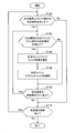
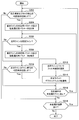
- FIG. 7 is a flowchart illustrating an example of a process flow by the deblocking filter 24 according to the first embodiment. The processing from step S102 to step S112 in FIG. 7 is repeated for each of all the boundaries (including the vertical boundary and the horizontal boundary) in the input image.
- the block determination unit 110 determines whether one boundary to be processed (hereinafter referred to as an attention boundary) satisfies a determination condition (for example, the above-described determination condition A) in units of blocks (step S102). If the determination condition for each block is not satisfied, the subsequent processing from step S104 to step S110 is skipped. On the other hand, if the determination condition for each block is satisfied, the process proceeds to step S104.
- a determination condition for example, the above-described determination condition A
- step S104 the line determination unit 120 determines whether one processing target line (hereinafter referred to as a target line) satisfies a line-by-line determination condition (for example, the above-described determination condition B ′) (step S104). ).
- a target line a line-by-line determination condition
- step S104 determines whether one processing target line (hereinafter referred to as a target line) satisfies a line-by-line determination condition (for example, the above-described determination condition B ′) (step S104).
- a line-by-line determination condition for example, the above-described determination condition B ′
- step S106 the strength selection unit 130 selects the strength of the filter to be applied to the target line according to, for example, the above-described conditions C1 ′ to C3 (step S106).
- the filtering unit 140 applies a deblocking filter to the target line (step S108).
- step S110 If no unprocessed line remains at the boundary of interest, the process proceeds to step S112.
- step S112 when an unprocessed boundary remains in the input image, a new attention boundary is set, and the process returns to step S102 (step S112). If there is no unprocessed boundary left, the process for the input image ends.
- step S104 in the flowchart of FIG. 7 may be omitted.
- step S104 and step S106 in the flowchart of FIG. 7 can be skipped.
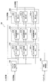
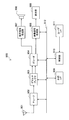
- FIG. 8 is a block diagram illustrating an example of a detailed configuration of the deblocking filter 24 according to the second embodiment.
- the deblocking filter 24 includes a block determination unit 110, a line determination section 220, an intensity selection section 230, a filtering section 240, and a determination control unit 150.
- the processing by the line determination section 220 can be performed for each of the boundaries determined by the block determination unit 110 as satisfying the determination condition for each block.
- the first line determination unit 222-1 determines whether or not the deblocking filter needs to be applied to the first line out of the lines orthogonal to each boundary, for example, according to the determination condition B ′ described above. Then, when it is determined that the first line satisfies the determination condition B ′, the first line determination unit 222-1 selects the first filter strength by the first intensity selection unit 232-1 and the first line for the first line. Filtering is performed by the filtering unit 242-1.
- the second line determination unit 222-2 determines whether or not the deblocking filter needs to be applied to the second line among the lines orthogonal to each boundary, for example, according to the determination condition B ′ described above. Then, when it is determined that the second line satisfies the determination condition B ′, the second line determination unit 222-2 selects the filter strength by the second intensity selection unit 232-2 and the second line for the second line. Filtering is performed by the filtering unit 242-2.
- the nth line determination unit 222-n determines whether or not the deblocking filter needs to be applied to the nth line among the lines orthogonal to each boundary, for example, according to the determination condition B ′ described above. Then, when it is determined that the nth line satisfies the determination condition B ′, the nth line determination unit 222-n selects the filter strength and the nth line for the nth line by the nth strength selection unit 232-n. Filtering is performed by the filtering unit 242-n.
- the intensity selection section 230 includes a plurality of intensity selection units 232-1 to 232-n.
- Each intensity selection unit 232 selects the intensity of the deblocking filter applied to the corresponding line, for example, according to the above-described conditions C1 ′ to C3.
- Each strength selection unit 232 then outputs information indicating the selected filter strength (for example, a flag indicating one of the strong filter and the weak filter) to the corresponding filtering unit 242 in the filtering section 240.
- the processing by the intensity selectors 232-1 to 232-n for a certain boundary can be performed in parallel.
- the filtering section 240 includes a plurality of filtering units 242-1 to 242-n.
- Each filtering unit 242 applies a deblocking filter to the corresponding lines of two adjacent blocks that are adjacent to each other across each boundary according to the determination results by the block determination unit 110 and the corresponding line determination unit 222.
- the filter configuration of each filtering unit 242 may be the same as the existing method described above. Then, each filtering unit 242 outputs the pixel value after filtering for the pixel to which the filter is applied, and the pixel value of the input image as the pixel value of the output image for the other pixels. Processing by the filtering units 242-1 to 242-n for a certain boundary can be performed in parallel.
- the determination of whether or not to apply the deblocking filter by the block determination unit 110 and the line determination section 220 may be controlled by the determination control unit 150 as in the first embodiment.
- the determination control unit 150 may control the line determination section 220 so as to determine in parallel whether to apply the deblocking filter to a plurality of lines in adjacent blocks.
- FIG. 9 is a flowchart illustrating an example of a processing flow by the deblocking filter 24 according to the second embodiment. The processing from step S202 to step S212 in FIG. 9 is repeated for each of all the boundaries (including the vertical boundary and the horizontal boundary) in the input image.
- the block determination unit 110 determines whether or not one attention boundary satisfies a determination condition (for example, the determination condition A described above) in units of blocks (step S202). If the determination condition for each block is not satisfied, the subsequent processing from step S204 to step S208 is skipped. On the other hand, if the determination condition for each block is satisfied, the process proceeds to step S204.
- a determination condition for example, the determination condition A described above
- the line determination units 222-1 to 222-n determine whether or not each line at the boundary of interest satisfies the determination condition for each line (for example, the determination condition B ′ described above) (step S204).
- the intensity selectors 232-1 to 232-n determine the intensity of the filter to be applied to each of the lines determined to be filtered by the line determination units 222-1 to 222-n among the lines of the boundary of interest. For example, the selection is performed according to the above-described conditions C1 ′ to C3 (step S206).
- the filtering units 242-1 to 242-n apply the deblocking filter to each of the lines of the boundary of interest determined as needing filtering by the line determination units 222-1 to 222-n (step S208). ).
- step S212 If there is no unprocessed boundary left, the process for the input image ends.
- step S204 in the flowchart of FIG. 9 may be omitted.
- step S204 and step S206 in the flowchart of FIG. 9 can be skipped.
- FIG. 10 is a block diagram illustrating an example of a detailed configuration of the deblocking filter 24 according to the third embodiment.
- the deblock filter 24 includes a block determination unit 110, a line determination unit 320, an intensity selection unit 330, a filtering unit 140, a control unit 350, and a parameter estimation unit 360.
- the parameter estimator 360 determines the value of the determination parameter for at least one line orthogonal to each boundary, out of the determination parameters used when the line determination unit 320 performs line-by-line determination. calculate. Then, the parameter estimation unit 360 estimates the determination parameter values for the other lines from the values calculated for the at least one line. Further, the parameter estimation unit 360 calculates and estimates the value of the strength selection parameter used when the strength selection unit 330 selects the filter strength in the same manner as the determination parameter.
- the at least one line serving as a basis for estimating parameter values for other lines is referred to as a basic line
- a line where parameter values are estimated is referred to as an estimated line.
- the estimation of the parameter value from the basic line to the estimation line may be performed by, for example, linear or nonlinear interpolation or extrapolation according to the line position.
- linear or nonlinear interpolation or extrapolation according to the line position.
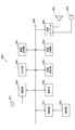
- three examples of parameter estimation processing by the parameter estimation unit 360 will be described with reference to FIGS. 11A to 11C.
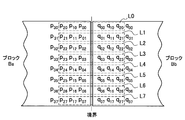
- FIG. 11A Two blocks Ba and Bb adjacent to each other across a boundary are shown.
- the basic lines are two lines L3 and L4 that are orthogonal to the boundary at the center of the boundary.
- the estimated lines are lines L0, L1, L2, L5, L6 and L7 other than the basic line.
- d3 i
- the parameter estimation unit 360 estimates the parameter value d2 j (j is 0 to 2, 5 to 7) for each estimation line using the calculated values of the intensity selection parameters d2 3 and d2 4 . Further, the parameter estimation unit 360 estimates the parameter value d3 j (j is 0 to 2, 5 to 7) for each estimation line using the calculated values of the intensity selection parameters d3 3 and d3 4 .
- the parameter estimation unit 360 determines the determination parameter d1 i (i is 0, 2, 4, or 6) for evaluating the above-described line-unit determination condition B ′ in relation to the first example. Calculate according to the formula described. Then, the parameter estimation unit 360 estimates the determination parameter d1 j (j is 1, 3, 5, or 7) for each estimated line by interpolation or extrapolation using the calculated determination parameter value. Similarly, the parameter estimation unit 360 calculates the parameters d2 i and d3 i for selecting the filter strength for the basic line. Then, the parameter estimation unit 360 estimates the intensity selection parameters d2 j and d3 j for each estimated line by interpolation or extrapolation using the calculated intensity selection parameter value.
- the basic lines are lines L0, L3, L4, and L7.
- the estimated lines are lines L1, L2, L5, and L6 other than the basic line.
- the parameter estimation unit 360 determines the determination parameter d1 i (i is 0, 3, 4, or 7) for evaluating the above-described line-unit determination condition B ′ in relation to the first example. Calculate according to the formula described. Then, the parameter estimation unit 360 estimates the determination parameter d1 j (j is 1, 2, 5, or 6) for each estimated line by interpolation using the calculated determination parameter value. Similarly, the parameter estimation unit 360 calculates the parameters d2 i and d3 i for selecting the filter strength for the basic line. Then, the parameter estimation unit 360 estimates the intensity selection parameters d2 j and d3 j for each estimation line by interpolation using the calculated intensity selection parameter value.
- the parameter estimation unit 360 outputs the value of the determination parameter calculated and estimated according to any of these three examples to the line determination unit 320, for example. Further, the parameter estimation unit 360 outputs the value of the intensity selection parameter calculated and estimated in the same manner to the intensity selection unit 330.
- the basic line set in the first example is a line perpendicular to the boundary at the center of the boundary.
- the pixel values of the pixels belonging to these basic lines are not updated by the deblocking filter applied along the same direction as the boundary.
- the difference in the line position between the basic line and the estimated line is smaller, so the parameter value can be estimated with higher accuracy. Can be realized.
- estimation accuracy can be further improved by estimating the parameter value for the estimated line only by interpolation.
- the line determination unit 320 determines, for each line orthogonal to each boundary, whether or not to apply the deblocking filter to two adjacent blocks adjacent to each other with the boundary interposed therebetween. In the present embodiment, the determination by the line determination unit 320 is performed using the determination parameter calculated or estimated by the parameter estimation unit 360.
- the determination condition for each line may be the same condition as the determination condition B ′ described above. -Condition B ': d1 i ⁇ ( ⁇ >> 1) If the size of each block is 8 ⁇ 8 pixels, i is an integer of 0 ⁇ i ⁇ 7.
- the line determination unit 320 may cause the strength selection unit 330 to select the filter strength for only the line that satisfies the condition B ′, for example. Instead, the determination by the line determination unit 320 and the selection of the filter strength by the strength selection unit 330 may be performed in parallel. The line determination unit 320 skips filtering by the filtering unit 140 for lines that do not satisfy the condition B ′.
- the intensity selection unit 330 selects the strength of the deblocking filter applied to each line by the filtering unit 140 for each line.
- the intensity selection by the intensity selection unit 330 is performed using the intensity selection parameter calculated or estimated by the parameter estimation unit 360. For example, for each line, the intensity selection unit 330 selects a strong filter when all of the following conditions C1 ′ to C3 are satisfied, and selects a weak filter when any one of the conditions is not satisfied.
- the determination parameter d1 i described above is also an intensity selection parameter in this case.
- the strength selection unit 330 outputs information representing the selected filter strength to the filtering unit 140 for each line.
- the control unit 350 controls parameter estimation processing by the parameter estimation unit 360 in addition to the control described in relation to the determination control unit 150 of the first and second embodiments. For example, the control unit 350 recognizes the line position of the processing target line and identifies whether each line is a basic line or an estimated line. The control unit 350 first causes the parameter estimation unit 360 to calculate the basic line determination parameter d1 and the basic line intensity selection parameters d2 and d3 from the pixel values of the basic line. Thereafter, the control unit 350 causes the parameter estimation unit 360 to estimate the estimation line determination parameter d1 and the estimation line intensity selection parameters d2 and d3 from the parameter values calculated for the basic line.
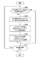
- FIG. 12 is a flowchart illustrating an example of a processing flow by the deblocking filter 24 according to the third embodiment. The processing from step S302 to step S318 in FIG. 12 is repeated for each of all the boundaries (including the vertical boundary and the horizontal boundary) in the input image.
- the block determination unit 110 determines whether or not one target boundary satisfies a determination unit for each block (for example, the above-described determination condition A) (step S302). If the determination condition for each block is not satisfied, the subsequent processing from step S304 to step S316 is skipped. On the other hand, if the determination condition for each block is satisfied, the process proceeds to step S304.
- a determination unit for each block for example, the above-described determination condition A
- step S304 the parameter estimation unit 360 calculates the determination parameter and the intensity selection parameter for the basic line orthogonal to the target boundary using the pixel values of the pixels belonging to the basic line (step S304).
- the basic line may be, for example, one or more lines set as in any of the three examples shown in FIGS. 11A to 11C.
- step S306 The processing from step S306 to step S316 is repeated for each target line, with each line orthogonal to the target boundary as the target line.
- the control unit 350 recognizes the line position of the target line and determines whether the target line is an estimated line (step S306). If the target line is an estimated line, the parameter estimation unit 360 estimates the determination parameter and the intensity selection parameter for the target line using the parameters calculated for the basic line, respectively (step S308). On the other hand, if the target line is a basic line, the process of step S308 is skipped.
- the line determination unit 320 uses the determination parameter calculated or estimated by the parameter estimation unit 360 to determine whether or not the line of interest satisfies the determination condition for each line (for example, the determination condition B ′ described above). Is determined (step S310).
- the determination condition for each line is not satisfied, the subsequent processing of step S312 and step S314 may be skipped.
- the process proceeds to step S312.
- step S312 the intensity selection unit 330 uses the intensity selection parameter calculated or estimated by the parameter estimation unit 360 to select the intensity of the filter to be applied to the target line, for example, according to the above-described conditions C1 ′ to C3. (Step S312).
- the filtering unit 140 applies the deblocking filter having the filter strength selected by the strength selecting unit 330 to the attention line (step S314).
- step S316 If no unprocessed line remains at the boundary of interest, the process proceeds to step S318.
- step S318 if an unprocessed boundary remains in the input image, a new attention boundary is set, and the process returns to step S302 (step S318). If there is no unprocessed boundary left, the process for the input image ends.
- the image encoding device 10 and the image decoding device 60 include a transmitter or a receiver in satellite broadcasting, cable broadcasting such as cable TV, distribution on the Internet, and distribution to terminals by cellular communication,
- the present invention can be applied to various electronic devices such as a recording apparatus that records an image on a medium such as an optical disk, a magnetic disk, and a flash memory, or a reproducing apparatus that reproduces an image from the storage medium.
- a recording apparatus that records an image on a medium such as an optical disk, a magnetic disk, and a flash memory
- a reproducing apparatus that reproduces an image from the storage medium.
- FIG. 13 shows an example of a schematic configuration of a television apparatus to which the above-described embodiment is applied.
- the television apparatus 900 includes an antenna 901, a tuner 902, a demultiplexer 903, a decoder 904, a video signal processing unit 905, a display unit 906, an audio signal processing unit 907, a speaker 908, an external interface 909, a control unit 910, a user interface 911, And a bus 912.
- Tuner 902 extracts a signal of a desired channel from a broadcast signal received via antenna 901, and demodulates the extracted signal. Then, the tuner 902 outputs the encoded bit stream obtained by the demodulation to the demultiplexer 903. In other words, the tuner 902 serves as a transmission unit in the television apparatus 900 that receives an encoded stream in which an image is encoded.
- the demultiplexer 903 separates the video stream and audio stream of the viewing target program from the encoded bit stream, and outputs each separated stream to the decoder 904. In addition, the demultiplexer 903 extracts auxiliary data such as EPG (Electronic Program Guide) from the encoded bit stream, and supplies the extracted data to the control unit 910. Note that the demultiplexer 903 may perform descrambling when the encoded bit stream is scrambled.
- EPG Electronic Program Guide
- the decoder 904 decodes the video stream and audio stream input from the demultiplexer 903. Then, the decoder 904 outputs the video data generated by the decoding process to the video signal processing unit 905. In addition, the decoder 904 outputs audio data generated by the decoding process to the audio signal processing unit 907.
- the video signal processing unit 905 reproduces the video data input from the decoder 904 and causes the display unit 906 to display the video.
- the video signal processing unit 905 may cause the display unit 906 to display an application screen supplied via a network.
- the video signal processing unit 905 may perform additional processing such as noise removal on the video data according to the setting.
- the video signal processing unit 905 may generate a GUI (Graphical User Interface) image such as a menu, a button, or a cursor, and superimpose the generated image on the output image.
- GUI Graphic User Interface
- the display unit 906 is driven by a drive signal supplied from the video signal processing unit 905, and displays a video or an image on a video screen of a display device (for example, a liquid crystal display, a plasma display, or an OLED).
- a display device for example, a liquid crystal display, a plasma display, or an OLED.
- the audio signal processing unit 907 performs reproduction processing such as D / A conversion and amplification on the audio data input from the decoder 904, and outputs audio from the speaker 908.
- the audio signal processing unit 907 may perform additional processing such as noise removal on the audio data.
- the external interface 909 is an interface for connecting the television apparatus 900 to an external device or a network.
- a video stream or an audio stream received via the external interface 909 may be decoded by the decoder 904. That is, the external interface 909 also has a role as a transmission unit in the television apparatus 900 that receives an encoded stream in which an image is encoded.
- the control unit 910 has a processor such as a CPU (Central Processing Unit) and a memory such as a RAM (Random Access Memory) and a ROM (Read Only Memory).
- the memory stores a program executed by the CPU, program data, EPG data, data acquired via a network, and the like.
- the program stored in the memory is read and executed by the CPU when the television device 900 is activated, for example.
- the CPU controls the operation of the television device 900 according to an operation signal input from the user interface 911, for example, by executing the program.
- the user interface 911 is connected to the control unit 910.
- the user interface 911 includes, for example, buttons and switches for the user to operate the television device 900, a remote control signal receiving unit, and the like.
- the user interface 911 detects an operation by the user via these components, generates an operation signal, and outputs the generated operation signal to the control unit 910.
- the bus 912 connects the tuner 902, the demultiplexer 903, the decoder 904, the video signal processing unit 905, the audio signal processing unit 907, the external interface 909, and the control unit 910 to each other.
- the decoder 904 has the function of the image decoding apparatus 60 according to the above-described embodiment. Accordingly, when decoding an image in the television apparatus 900, it is possible to more appropriately determine the range to which the deblocking filter is applied, and improve the image quality.
- FIG. 14 shows an example of a schematic configuration of a mobile phone to which the above-described embodiment is applied.
- a mobile phone 920 includes an antenna 921, a communication unit 922, an audio codec 923, a speaker 924, a microphone 925, a camera unit 926, an image processing unit 927, a demultiplexing unit 928, a recording / reproducing unit 929, a display unit 930, a control unit 931, an operation A portion 932 and a bus 933.
- the antenna 921 is connected to the communication unit 922.
- the speaker 924 and the microphone 925 are connected to the audio codec 923.
- the operation unit 932 is connected to the control unit 931.
- the bus 933 connects the communication unit 922, the audio codec 923, the camera unit 926, the image processing unit 927, the demultiplexing unit 928, the recording / reproducing unit 929, the display unit 930, and the control unit 931 to each other.
- the mobile phone 920 has various operation modes including a voice call mode, a data communication mode, a shooting mode, and a videophone mode, and is used for sending and receiving voice signals, sending and receiving e-mail or image data, taking images, and recording data. Perform the action.
- the analog voice signal generated by the microphone 925 is supplied to the voice codec 923.
- the audio codec 923 converts an analog audio signal into audio data, A / D converts the compressed audio data, and compresses it. Then, the audio codec 923 outputs the compressed audio data to the communication unit 922.
- the communication unit 922 encodes and modulates the audio data and generates a transmission signal. Then, the communication unit 922 transmits the generated transmission signal to a base station (not shown) via the antenna 921. In addition, the communication unit 922 amplifies a radio signal received via the antenna 921 and performs frequency conversion to acquire a received signal.
- the communication unit 922 demodulates and decodes the received signal to generate audio data, and outputs the generated audio data to the audio codec 923.
- the audio codec 923 expands the audio data and performs D / A conversion to generate an analog audio signal. Then, the audio codec 923 supplies the generated audio signal to the speaker 924 to output audio.
- the control unit 931 generates character data constituting the e-mail in response to an operation by the user via the operation unit 932.
- the control unit 931 causes the display unit 930 to display characters.
- the control unit 931 generates e-mail data in response to a transmission instruction from the user via the operation unit 932, and outputs the generated e-mail data to the communication unit 922.
- the communication unit 922 encodes and modulates email data and generates a transmission signal. Then, the communication unit 922 transmits the generated transmission signal to a base station (not shown) via the antenna 921.
- the communication unit 922 amplifies a radio signal received via the antenna 921 and performs frequency conversion to acquire a received signal.
- the communication unit 922 demodulates and decodes the received signal to restore the email data, and outputs the restored email data to the control unit 931.
- the control unit 931 displays the content of the electronic mail on the display unit 930 and stores the electronic mail data in the storage medium of the recording / reproducing unit 929.
- the recording / reproducing unit 929 has an arbitrary readable / writable storage medium.
- the storage medium may be a built-in storage medium such as a RAM or a flash memory, or an externally mounted storage medium such as a hard disk, a magnetic disk, a magneto-optical disk, an optical disk, a USB memory, or a memory card. May be.
- the camera unit 926 images a subject to generate image data, and outputs the generated image data to the image processing unit 927.
- the image processing unit 927 encodes the image data input from the camera unit 926 and stores the encoded stream in the storage medium of the recording / playback unit 929.
- the demultiplexing unit 928 multiplexes the video stream encoded by the image processing unit 927 and the audio stream input from the audio codec 923, and the multiplexed stream is the communication unit 922. Output to.
- the communication unit 922 encodes and modulates the stream and generates a transmission signal. Then, the communication unit 922 transmits the generated transmission signal to a base station (not shown) via the antenna 921.
- the communication unit 922 amplifies a radio signal received via the antenna 921 and performs frequency conversion to acquire a received signal.
- These transmission signal and reception signal may include an encoded bit stream.
- the communication unit 922 demodulates and decodes the received signal to restore the stream, and outputs the restored stream to the demultiplexing unit 928.
- the demultiplexing unit 928 separates the video stream and the audio stream from the input stream, and outputs the video stream to the image processing unit 927 and the audio stream to the audio codec 923.
- the image processing unit 927 decodes the video stream and generates video data.
- the video data is supplied to the display unit 930, and a series of images is displayed on the display unit 930.
- the audio codec 923 decompresses the audio stream and performs D / A conversion to generate an analog audio signal. Then, the audio codec 923 supplies the generated audio signal to the speaker 924 to output audio.
- the image processing unit 927 has the functions of the image encoding device 10 and the image decoding device 60 according to the above-described embodiment. Accordingly, when encoding and decoding an image with the mobile phone 920, it is possible to more appropriately determine a range to which the deblocking filter is applied, and to improve the image quality.
- FIG. 15 shows an example of a schematic configuration of a recording / reproducing apparatus to which the above-described embodiment is applied.
- the recording / reproducing device 940 encodes audio data and video data of a received broadcast program and records the encoded data on a recording medium.
- the recording / reproducing device 940 may encode audio data and video data acquired from another device and record them on a recording medium, for example.
- the recording / reproducing device 940 reproduces data recorded on the recording medium on a monitor and a speaker, for example, in accordance with a user instruction. At this time, the recording / reproducing device 940 decodes the audio data and the video data.
- the recording / reproducing device 940 includes a tuner 941, an external interface 942, an encoder 943, an HDD (Hard Disk Drive) 944, a disk drive 945, a selector 946, a decoder 947, an OSD (On-Screen Display) 948, a control unit 949, and a user interface. 950.
- Tuner 941 extracts a signal of a desired channel from a broadcast signal received via an antenna (not shown), and demodulates the extracted signal. Then, the tuner 941 outputs the encoded bit stream obtained by the demodulation to the selector 946. That is, the tuner 941 has a role as a transmission unit in the recording / reproducing apparatus 940.
- the external interface 942 is an interface for connecting the recording / reproducing apparatus 940 to an external device or a network.
- the external interface 942 may be, for example, an IEEE 1394 interface, a network interface, a USB interface, or a flash memory interface.
- video data and audio data received via the external interface 942 are input to the encoder 943. That is, the external interface 942 serves as a transmission unit in the recording / reproducing device 940.
- the encoder 943 encodes video data and audio data when the video data and audio data input from the external interface 942 are not encoded. Then, the encoder 943 outputs the encoded bit stream to the selector 946.
- the HDD 944 records an encoded bit stream in which content data such as video and audio is compressed, various programs, and other data on an internal hard disk. Also, the HDD 944 reads out these data from the hard disk when playing back video and audio.
- the disk drive 945 performs recording and reading of data to and from the mounted recording medium.
- the recording medium loaded in the disk drive 945 may be, for example, a DVD disk (DVD-Video, DVD-RAM, DVD-R, DVD-RW, DVD + R, DVD + RW, etc.) or a Blu-ray (registered trademark) disk. .
- the selector 946 selects an encoded bit stream input from the tuner 941 or the encoder 943 when recording video and audio, and outputs the selected encoded bit stream to the HDD 944 or the disk drive 945. In addition, the selector 946 outputs the encoded bit stream input from the HDD 944 or the disk drive 945 to the decoder 947 during video and audio reproduction.
- the decoder 947 decodes the encoded bit stream and generates video data and audio data. Then, the decoder 947 outputs the generated video data to the OSD 948. The decoder 904 outputs the generated audio data to an external speaker.
- the OSD 948 reproduces the video data input from the decoder 947 and displays the video. Further, the OSD 948 may superimpose a GUI image such as a menu, a button, or a cursor on the video to be displayed.
- a GUI image such as a menu, a button, or a cursor
- the control unit 949 includes a processor such as a CPU and memories such as a RAM and a ROM.
- the memory stores a program executed by the CPU, program data, and the like.
- the program stored in the memory is read and executed by the CPU when the recording / reproducing apparatus 940 is activated, for example.
- the CPU controls the operation of the recording / reproducing device 940 according to an operation signal input from the user interface 950, for example, by executing the program.
- the user interface 950 is connected to the control unit 949.
- the user interface 950 includes, for example, buttons and switches for the user to operate the recording / reproducing device 940, a remote control signal receiving unit, and the like.
- the user interface 950 detects an operation by the user via these components, generates an operation signal, and outputs the generated operation signal to the control unit 949.
- the encoder 943 has the function of the image encoding apparatus 10 according to the above-described embodiment.
- the decoder 947 has the function of the image decoding device 60 according to the above-described embodiment.
- FIG. 16 illustrates an example of a schematic configuration of an imaging apparatus to which the above-described embodiment is applied.
- the imaging device 960 images a subject to generate an image, encodes the image data, and records it on a recording medium.
- the imaging device 960 includes an optical block 961, an imaging unit 962, a signal processing unit 963, an image processing unit 964, a display unit 965, an external interface 966, a memory 967, a media drive 968, an OSD 969, a control unit 970, a user interface 971, and a bus. 972.
- the optical block 961 is connected to the imaging unit 962.
- the imaging unit 962 is connected to the signal processing unit 963.
- the display unit 965 is connected to the image processing unit 964.
- the user interface 971 is connected to the control unit 970.
- the bus 972 connects the image processing unit 964, the external interface 966, the memory 967, the media drive 968, the OSD 969, and the control unit 970 to each other.
- the optical block 961 includes a focus lens and a diaphragm mechanism.
- the optical block 961 forms an optical image of the subject on the imaging surface of the imaging unit 962.
- the imaging unit 962 includes an image sensor such as a CCD or a CMOS, and converts an optical image formed on the imaging surface into an image signal as an electrical signal by photoelectric conversion. Then, the imaging unit 962 outputs the image signal to the signal processing unit 963.
- the signal processing unit 963 performs various camera signal processing such as knee correction, gamma correction, and color correction on the image signal input from the imaging unit 962.
- the signal processing unit 963 outputs the image data after the camera signal processing to the image processing unit 964.
- the image processing unit 964 encodes the image data input from the signal processing unit 963 and generates encoded data. Then, the image processing unit 964 outputs the generated encoded data to the external interface 966 or the media drive 968. The image processing unit 964 also decodes encoded data input from the external interface 966 or the media drive 968 to generate image data. Then, the image processing unit 964 outputs the generated image data to the display unit 965. In addition, the image processing unit 964 may display the image by outputting the image data input from the signal processing unit 963 to the display unit 965. Further, the image processing unit 964 may superimpose display data acquired from the OSD 969 on an image output to the display unit 965.
- the OSD 969 generates a GUI image such as a menu, a button, or a cursor, for example, and outputs the generated image to the image processing unit 964.
- the external interface 966 is configured as a USB input / output terminal, for example.
- the external interface 966 connects the imaging device 960 and a printer, for example, when printing an image.
- a drive is connected to the external interface 966 as necessary.
- a removable medium such as a magnetic disk or an optical disk is attached to the drive, and a program read from the removable medium can be installed in the imaging device 960.
- the external interface 966 may be configured as a network interface connected to a network such as a LAN or the Internet. That is, the external interface 966 has a role as a transmission unit in the imaging device 960.
- the recording medium mounted on the media drive 968 may be any readable / writable removable medium such as a magnetic disk, a magneto-optical disk, an optical disk, or a semiconductor memory. Further, a recording medium may be fixedly attached to the media drive 968, and a non-portable storage unit such as an internal hard disk drive or an SSD (Solid State Drive) may be configured.
- a non-portable storage unit such as an internal hard disk drive or an SSD (Solid State Drive) may be configured.
- the control unit 970 includes a processor such as a CPU and memories such as a RAM and a ROM.
- the memory stores a program executed by the CPU, program data, and the like.
- the program stored in the memory is read and executed by the CPU when the imaging device 960 is activated, for example.
- the CPU controls the operation of the imaging device 960 according to an operation signal input from the user interface 971, for example, by executing the program.
- the user interface 971 is connected to the control unit 970.
- the user interface 971 includes, for example, buttons and switches for the user to operate the imaging device 960.
- the user interface 971 detects an operation by the user via these components, generates an operation signal, and outputs the generated operation signal to the control unit 970.
- the image processing unit 964 has the functions of the image encoding device 10 and the image decoding device 60 according to the above-described embodiment. Accordingly, when encoding and decoding an image by the imaging device 960, it is possible to more appropriately determine a range to which the deblocking filter is applied, and improve the image quality.
- the determination for each line can be skipped for the boundary determined that the deblocking filter should not be applied based on the determination in units of blocks. According to such a configuration, since access to all lines is avoided for boundaries that do not require filtering as a whole, an increase in processing amount can be suppressed.
- whether or not to apply a deblocking filter to each line is determined by using a determination parameter value calculated from a reference pixel value belonging only to the line as a determination threshold value. It is determined by comparing. Therefore, the determination for each line can be realized with a simple configuration in which each line is sequentially accessed.
- the necessity of applying the deblocking filter is determined in parallel for a plurality of lines at a certain boundary. Therefore, the processing time required for determination for each line can be reduced as a whole.
- parameter values used for determining whether filtering is necessary for an estimated line or selecting a filter strength among a plurality of lines orthogonal to a certain boundary are calculated for a basic line. Estimated from the measured parameter values. Accordingly, it is possible to reduce the processing cost associated with repeated calculation of parameter values. At that time, by setting a line perpendicular to the boundary at the center of the boundary as a basic line, it is possible to determine the necessity of filtering for each line and to select the filter strength for the filtering process for the other boundary. Can be performed in parallel. Further, if the difference in the line position between the basic line and the estimated line is made smaller, the parameter value can be estimated with higher accuracy.
- the user who develops the apparatus can specify the desired one of the improvement in the image quality by the determination in line units and the high processing speed by the determination in block units via the parameter.
- the size of the processing unit of the deblocking filter or the size of the macroblock is not limited to the example described in this specification, and may be other sizes.
- H.M The size of the H.264 / AVC macroblock is fixed to 16 ⁇ 16 pixels, whereas the size of the HEVC coding unit can be dynamically specified for each sequence.
- the coding unit of HEVC is also called a coding tree block (Coding Tree Block).
- the coding unit having the largest size is the largest coding unit (LCU), and the coding unit having the smallest size is the smallest. It is called a coding unit (SCU: Smallest Coding Unit).
- the range of sizes of usable coding units is defined. Furthermore, by specifying the value of split_flag, the size of the coding unit used in each sequence is specified.
- the shape of the encoding unit is usually a square, and the size of one side is expressed by a power of 2.
- the coding unit may be divided into prediction units (PU: Prediction Unit) that are processing units for intra prediction or inter prediction.
- the coding unit can also be divided into transform units (TUs) that are orthogonal transform processing units. In HEVC, in addition to 4 ⁇ 4 pixels and 8 ⁇ 8 pixels, conversion units having sizes of 16 ⁇ 16 pixels and 32 ⁇ 32 pixels can be used.
- the term block in this specification includes the concept of a macroblock, a coding unit, a prediction unit, a transform unit, or various other units.
- the block size may be fixed or may change dynamically.
- the method of transmitting information used for the deblocking filter processing from the encoding side to the decoding side is not limited to the method of multiplexing these information in the header of the encoded stream.
- these pieces of information may be transmitted or recorded as separate data associated with the encoded bitstream without being multiplexed into the encoded bitstream.
- the term “associate” means that an image (which may be a part of an image such as a slice or a block) included in the bitstream and information corresponding to the image can be linked at the time of decoding. Means. That is, information may be transmitted on a transmission path different from that of the image (or bit stream).
- the information may be recorded on a recording medium (or another recording area of the same recording medium) different from the image (or bit stream). Furthermore, the information and the image (or the bit stream) may be associated with each other in an arbitrary unit such as a plurality of frames, one frame, or a part of the frame.
Landscapes
- Engineering & Computer Science (AREA)
- Multimedia (AREA)
- Signal Processing (AREA)
- Compression Or Coding Systems Of Tv Signals (AREA)
Abstract
【課題】デブロックフィルタが適用される範囲をより適切に判定すること。 【解決手段】符号化ストリームを復号して画像を生成する復号部と、前記復号部により生成された前記画像内で境界を挟んで互いに隣接する隣接ブロック内の前記境界と直交するラインごとに、デブロックフィルタを適用するかを判定するライン判定部と、前記ライン判定部によりデブロックフィルタを適用すると判定された各ラインにデブロックフィルタを適用するフィルタリング部と、を備える画像処理装置、が提供される。
Description
本開示は、画像処理装置及び画像処理方法に関する。
画像符号化方式の標準仕様の1つであるH.264/AVCでは、画像の符号化の際に生じるブロック歪みに起因する画質の劣化を抑制するために、例えば4×4画素のブロックごとにブロック境界にデブロックフィルタが適用される。このデブロックフィルタのために要する処理量は多大であり、例えば、画像の復号の際の全処理量の50%を占めることもあると言われている。
次世代の画像符号化方式であるHEVC(High Efficiency Video Coding)の標準化作業では、JCTVC-A119(下記非特許文献1参照)において、8×8画素以上のサイズのブロックごとにデブロックフィルタを適用することが提案されている。JCTVC-A119において提案された手法では、デブロックフィルタを適用する最小単位のブロックサイズが拡大される。当該手法でも、H.264/AVCと同様、ブロック単位でデブロックフィルタの適用の要否が判定される。
K.Ugur (Nokia), K.R.Andersson (LM Ericsson), A.Fuldseth (Tandberg Telecom), "JCTVC-A119:Video coding technology proposal by Tandberg, Nokia, and Ericsson", Documents of the first meeting of the Joint Collaborative Team on Video Coding (JCT-VC), Dresden, Germany, 15-23 April, 2010.
しかしながら、ブロック歪みに起因する画質の劣化は、必ずしもブロック内に一様に現れるわけではない。即ち、デブロックフィルタを適用すべきと判定されたブロックの一部の画質は既に良好である可能性がある。また、デブロックフィルタを適用すべきでないと判定されたブロックの一部の画質が実際には劣化している可能性もある。良好な画質を有する部分にデブロックフィルタを適用すれば、かえってその画質が損われかねない。また、劣化した画質を有する部分にデブロックフィルタを適用しなければ、画質は向上されない。
従って、デブロックフィルタが適用される範囲をより適切に判定することのできる、画像処理装置及び画像処理方法が提供されることが望ましい。
ある実施形態によれば、符号化ストリームを復号して画像を生成する復号部と、前記復号部により生成された前記画像内で境界を挟んで互いに隣接する隣接ブロック内の前記境界と直交するラインごとに、デブロックフィルタを適用するかを判定するライン判定部と、前記ライン判定部によりデブロックフィルタを適用すると判定された各ラインにデブロックフィルタを適用するフィルタリング部と、を備える画像処理装置が提供される。
上記画像処理装置は、典型的には、画像を復号する画像復号装置として実現され得る。
また、別の実施形態によれば、符号化ストリームを復号して画像を生成することと、生成された前記画像内で境界を挟んで互いに隣接する隣接ブロック内の前記境界と直交するラインごとに、デブロックフィルタを適用するかを判定することと、デブロックフィルタを適用すると判定された各ラインにデブロックフィルタを適用することと、を含む画像処理方法が提供される。
また、別の実施形態によれば、符号化対象画像を符号化する際にローカルデコードされた画像内で境界を挟んで互いに隣接する隣接ブロック内の前記境界と直交するラインごとに、デブロックフィルタを適用するかを判定するライン判定部と、前記ライン判定部によりデブロックフィルタを適用すると判定された各ラインにデブロックフィルタを適用するフィルタリング部と、前記フィルタリング部によりフィルタリングされた画像を用いて、前記符号化対象画像を符号化する符号化部と、を備える画像処理装置が提供される。
上記画像処理装置は、典型的には、画像を符号化する画像符号化装置として実現され得る。
また、別の実施形態によれば、符号化対象画像を符号化する際にローカルデコードされた画像内で境界を挟んで互いに隣接する隣接ブロック内の前記境界と直交するラインごとに、デブロックフィルタを適用するかを判定することと、デブロックフィルタを適用すると判定された各ラインにデブロックフィルタを適用することと、フィルタリングされた画像を用いて、前記符号化対象画像を符号化することと、を含む画像処理方法が提供される。
本開示に係る画像処理装置及び画像処理方法によれば、デブロックフィルタが適用される範囲をより適切に判定することができる。
以下に添付図面を参照しながら、本開示の好適な実施の形態について詳細に説明する。なお、本明細書及び図面において、実質的に同一の機能構成を有する構成要素については、同一の符号を付すことにより重複説明を省略する。
また、以下の順序で説明を行う。
1.装置の概要
1-1.画像符号化装置
1-2.画像復号装置
2.既存の手法の説明
3.第1の実施例
3-1.デブロックフィルタの構成例
3-2.処理の流れ
4.第2の実施例
4-1.デブロックフィルタの構成例
4-2.処理の流れ
5.第3の実施例
5-1.デブロックフィルタの構成例
5-2.処理の流れ
6.応用例
7.まとめ
1.装置の概要
1-1.画像符号化装置
1-2.画像復号装置
2.既存の手法の説明
3.第1の実施例
3-1.デブロックフィルタの構成例
3-2.処理の流れ
4.第2の実施例
4-1.デブロックフィルタの構成例
4-2.処理の流れ
5.第3の実施例
5-1.デブロックフィルタの構成例
5-2.処理の流れ
6.応用例
7.まとめ
<1.装置の概要>
まず、図1及び図2を用いて、本明細書で開示する技術を適用可能な一例としての装置の概要を説明する。本明細書で開示する技術は、例えば、画像符号化装置及び画像復号装置に適用可能である。
まず、図1及び図2を用いて、本明細書で開示する技術を適用可能な一例としての装置の概要を説明する。本明細書で開示する技術は、例えば、画像符号化装置及び画像復号装置に適用可能である。
[1-1.画像符号化装置]
図1は、一実施形態に係る画像符号化装置10の構成の一例を示すブロック図である。図1を参照すると、画像符号化装置10は、A/D(Analogue to Digital)変換部11、並べ替えバッファ12、減算部13、直交変換部14、量子化部15、可逆符号化部16、蓄積バッファ17、レート制御部18、逆量子化部21、逆直交変換部22、加算部23、デブロックフィルタ24a、フレームメモリ25、セレクタ26、イントラ予測部30、動き探索部40、及びモード選択部50を備える。
図1は、一実施形態に係る画像符号化装置10の構成の一例を示すブロック図である。図1を参照すると、画像符号化装置10は、A/D(Analogue to Digital)変換部11、並べ替えバッファ12、減算部13、直交変換部14、量子化部15、可逆符号化部16、蓄積バッファ17、レート制御部18、逆量子化部21、逆直交変換部22、加算部23、デブロックフィルタ24a、フレームメモリ25、セレクタ26、イントラ予測部30、動き探索部40、及びモード選択部50を備える。
A/D変換部11は、アナログ形式で入力される画像信号をデジタル形式の画像データに変換し、一連のデジタル画像データを並べ替えバッファ12へ出力する。
並べ替えバッファ12は、A/D変換部11から入力される一連の画像データに含まれる画像を並べ替える。並べ替えバッファ12は、符号化処理に係るGOP(Group of Pictures)構造に応じて画像を並べ替えた後、並べ替え後の画像データを減算部13、イントラ予測部30及び動き探索部40へ出力する。
減算部13には、並べ替えバッファ12から入力される画像データ、及び後に説明するモード選択部50により選択される予測画像データが供給される。減算部13は、並べ替えバッファ12から入力される画像データとモード選択部50から入力される予測画像データとの差分である予測誤差データを算出し、算出した予測誤差データを直交変換部14へ出力する。
直交変換部14は、減算部13から入力される予測誤差データについて直交変換を行う。直交変換部14により実行される直交変換は、例えば、離散コサイン変換(Discrete Cosine Transform:DCT)又はカルーネン・レーベ変換などであってよい。直交変換部14は、直交変換処理により取得される変換係数データを量子化部15へ出力する。
量子化部15には、直交変換部14から入力される変換係数データ、及び後に説明するレート制御部18からのレート制御信号が供給される。量子化部15は、変換係数データを量子化し、量子化後の変換係数データ(以下、量子化データという)を可逆符号化部16及び逆量子化部21へ出力する。また、量子化部15は、レート制御部18からのレート制御信号に基づいて量子化パラメータ(量子化スケール)を切替えることにより、可逆符号化部16に入力される量子化データのビットレートを変化させる。
可逆符号化部16には、量子化部15から入力される量子化データ、及び、後に説明するイントラ予測部30又は動き探索部40により生成されモード選択部50により選択されるイントラ予測又はインター予測に関する情報が供給される。イントラ予測に関する情報は、例えば、ブロックごとの最適なイントラ予測モードを示す予測モード情報を含み得る。また、インター予測に関する情報は、例えば、ブロックごとの動きベクトルの予測のための予測モード情報、差分動きベクトル情報、及び参照画像情報などを含み得る。
可逆符号化部16は、量子化データについて可逆符号化処理を行うことにより、符号化ストリームを生成する。可逆符号化部16による可逆符号化は、例えば、可変長符号化、又は算術符号化などであってよい。また、可逆符号化部16は、上述したイントラ予測に関する情報又はインター予測に関する情報を、符号化ストリームのヘッダ(例えばブロックヘッダ又はスライスヘッダなど)内に多重化する。そして、可逆符号化部16は、生成した符号化ストリームを蓄積バッファ17へ出力する。
蓄積バッファ17は、可逆符号化部16から入力される符号化ストリームを一時的に蓄積する。そして、蓄積バッファ17は、蓄積した符号化ストリームを、伝送路(又は画像符号化装置10からの出力線)の帯域に応じたレートで出力する。
レート制御部18は、蓄積バッファ17の空き容量を監視する。そして、レート制御部18は、蓄積バッファ17の空き容量に応じてレート制御信号を生成し、生成したレート制御信号を量子化部15へ出力する。例えば、レート制御部18は、蓄積バッファ17の空き容量が少ない時には、量子化データのビットレートを低下させるためのレート制御信号を生成する。また、例えば、レート制御部18は、蓄積バッファ17の空き容量が十分大きい時には、量子化データのビットレートを高めるためのレート制御信号を生成する。
逆量子化部21は、量子化部15から入力される量子化データについて逆量子化処理を行う。そして、逆量子化部21は、逆量子化処理により取得される変換係数データを、逆直交変換部22へ出力する。
逆直交変換部22は、逆量子化部21から入力される変換係数データについて逆直交変換処理を行うことにより、予測誤差データを復元する。そして、逆直交変換部22は、復元した予測誤差データを加算部23へ出力する。
加算部23は、逆直交変換部22から入力される復元された予測誤差データとモード選択部50から入力される予測画像データとを加算することにより、復号画像データを生成する。そして、加算部23は、生成した復号画像データをデブロックフィルタ24a及びフレームメモリ25へ出力する。
デブロックフィルタ24aは、画像の符号化の際に生じるブロック歪みを減少させるためのフィルタリング処理を行う。より具体的には、デブロックフィルタ24aは、加算部23から入力される復号画像データ内の各ブロック境界について、ラインごとにフィルタリングの要否を判定する。そして、デブロックフィルタ24aは、フィルタを適用すべきであると判定したラインにデブロックフィルタを適用する。ブロック境界が垂直境界である場合には、上記ラインは、垂直境界と直交する行に相当する。ブロック境界が水平境界である場合には、上記ラインは、水平境界と直交する列に相当する。デブロックフィルタ24aには、加算部23からの復号画像データに加えて、フィルタリングの要否の判定のために使用される情報(例えば、モード情報、変換係数情報及び動きベクトル情報)も入力される。その後、デブロックフィルタ24aは、ブロック歪みの除去されたフィルタリング後の復号画像データをフレームメモリ25へ出力する。なお、デブロックフィルタ24aによる処理について、後に詳細に説明する。
フレームメモリ25は、加算部23から入力される復号画像データ、及びデブロックフィルタ24aから入力されるフィルタリング後の復号画像データを記憶する。
セレクタ26は、イントラ予測のために使用されるフィルタリング前の復号画像データをフレームメモリ25から読み出し、読み出した復号画像データを参照画像データとしてイントラ予測部30に供給する。また、セレクタ26は、インター予測のために使用されるフィルタリング後の復号画像データをフレームメモリ25から読み出し、読み出した復号画像データを参照画像データとして動き探索部40に供給する。
イントラ予測部30は、並べ替えバッファ12から入力される符号化対象の画像データ、及びセレクタ26を介して供給される復号画像データに基づいて、各イントラ予測モードのイントラ予測処理を行う。例えば、イントラ予測部30は、各イントラ予測モードによる予測結果を所定のコスト関数を用いて評価する。そして、イントラ予測部30は、コスト関数値が最小となるイントラ予測モード、即ち圧縮率が最も高くなるイントラ予測モードを、最適なイントラ予測モードとして選択する。さらに、イントラ予測部30は、当該最適なイントラ予測モードを表す予測モード情報を含むイントラ予測に関する情報、予測画像データ、及びコスト関数値を、モード選択部50へ出力する。
動き探索部40は、並べ替えバッファ12から入力される符号化対象の画像データ、及びセレクタ26を介して供給される復号画像データに基づいて、インター予測処理(フレーム間予測処理)を行う。例えば、動き探索部40は、各予測モードによる予測結果を所定のコスト関数を用いて評価する。次に、動き探索部40は、コスト関数値が最小となる予測モード、即ち圧縮率が最も高くなる予測モードを、最適な予測モードとして選択する。また、動き探索部40は、当該最適な予測モードに従って予測画像データを生成する。そして、動き探索部40は、選択した最適な予測モードを表す予測モード情報を含むインター予測に関する情報、予測画像データ、及びコスト関数値を、モード選択部50へ出力する。
モード選択部50は、イントラ予測部30から入力されるイントラ予測に関するコスト関数値と動き探索部40から入力されるインター予測に関するコスト関数値とを比較する。そして、モード選択部50は、イントラ予測及びインター予測のうちコスト関数値がより少ない予測手法を選択する。モード選択部50は、イントラ予測を選択した場合には、イントラ予測に関する情報を可逆符号化部16へ出力すると共に、予測画像データを減算部13及び加算部23へ出力する。また、モード選択部50は、インター予測を選択した場合には、インター予測に関する上述した情報を可逆符号化部16へ出力すると共に、予測画像データを減算部13及び加算部23へ出力する。
[1-2.画像復号装置]
図2は、一実施形態に係る画像復号装置60の構成の一例を示すブロック図である。図2を参照すると、画像復号装置60は、蓄積バッファ61、可逆復号部62、逆量子化部63、逆直交変換部64、加算部65、デブロックフィルタ24b、並べ替えバッファ67、D/A(Digital to Analogue)変換部68、フレームメモリ69、セレクタ70及び71、イントラ予測部80、並びに動き補償部90を備える。
図2は、一実施形態に係る画像復号装置60の構成の一例を示すブロック図である。図2を参照すると、画像復号装置60は、蓄積バッファ61、可逆復号部62、逆量子化部63、逆直交変換部64、加算部65、デブロックフィルタ24b、並べ替えバッファ67、D/A(Digital to Analogue)変換部68、フレームメモリ69、セレクタ70及び71、イントラ予測部80、並びに動き補償部90を備える。
蓄積バッファ61は、伝送路を介して入力される符号化ストリームを一時的に蓄積する。
可逆復号部62は、蓄積バッファ61から入力される符号化ストリームを、符号化の際に使用された符号化方式に従って復号する。また、可逆復号部62は、符号化ストリームのヘッダ領域に多重化されている情報を復号する。符号化ストリームのヘッダ領域に多重化されている情報とは、例えば、ブロックヘッダ内のイントラ予測に関する情報及びインター予測に関する情報を含み得る。可逆復号部62は、イントラ予測に関する情報をイントラ予測部80へ出力する。また、可逆復号部62は、インター予測に関する情報を動き補償部90へ出力する。
逆量子化部63は、可逆復号部62による復号後の量子化データを逆量子化する。逆直交変換部64は、符号化の際に使用された直交変換方式に従い、逆量子化部63から入力される変換係数データについて逆直交変換を行うことにより、予測誤差データを生成する。そして、逆直交変換部64は、生成した予測誤差データを加算部65へ出力する。
加算部65は、逆直交変換部64から入力される予測誤差データと、セレクタ71から入力される予測画像データとを加算することにより、復号画像データを生成する。そして、加算部65は、生成した復号画像データをデブロックフィルタ24b及びフレームメモリ69へ出力する。
デブロックフィルタ24bは、復号された画像に現れるブロック歪みを減少させるためのフィルタリング処理を行う。より具体的には、デブロックフィルタ24bは、加算部65から入力される復号画像データ内の各ブロック境界について、ラインごとにフィルタリングの要否を判定する。そして、デブロックフィルタ24aは、フィルタを適用すべきであると判定したラインにデブロックフィルタを適用する。デブロックフィルタ24bには、加算部65からの復号画像データに加えて、フィルタリングの要否の判定のために使用される情報も入力される。その後、デブロックフィルタ24bは、ブロック歪みの除去されたフィルタリング後の復号画像データを並べ替えバッファ67及びフレームメモリ69へ出力する。なお、デブロックフィルタ24bによる処理について、後に詳細に説明する。
並べ替えバッファ67は、デブロックフィルタ24bから入力される画像を並べ替えることにより、時系列の一連の画像データを生成する。そして、並べ替えバッファ67は、生成した画像データをD/A変換部68へ出力する。
D/A変換部68は、並べ替えバッファ67から入力されるデジタル形式の画像データをアナログ形式の画像信号に変換する。そして、D/A変換部68は、例えば、画像復号装置60と接続されるディスプレイ(図示せず)にアナログ画像信号を出力することにより、画像を表示させる。
フレームメモリ69は、加算部65から入力されるフィルタリング前の復号画像データ、及びデブロックフィルタ24bから入力されるフィルタリング後の復号画像データを記憶する。
セレクタ70は、可逆復号部62により取得されるモード情報に応じて、画像内のブロックごとに、フレームメモリ69からの画像データの出力先をイントラ予測部80と動き補償部90との間で切り替える。例えば、セレクタ70は、イントラ予測モードが指定された場合には、フレームメモリ69から供給されるフィルタリング前の復号画像データを参照画像データとしてイントラ予測部80へ出力する。また、セレクタ70は、インター予測モードが指定された場合には、フレームメモリ69から供給されるフィルタリング後の復号画像データを参照画像データとして動き補償部90へ出力する。
セレクタ71は、可逆復号部62により取得されるモード情報に応じて、画像内のブロックごとに、加算部65へ供給すべき予測画像データの出力元をイントラ予測部80と動き補償部90との間で切り替える。例えば、セレクタ71は、イントラ予測モードが指定された場合には、イントラ予測部80から出力される予測画像データを加算部65へ供給する。セレクタ71は、インター予測モードが指定された場合には、動き補償部90から出力される予測画像データを加算部65へ供給する。
イントラ予測部80は、可逆復号部62から入力されるイントラ予測に関する情報とフレームメモリ69からの参照画像データとに基づいて画素値の画面内予測を行い、予測画像データを生成する。そして、イントラ予測部80は、生成した予測画像データをセレクタ71へ出力する。
動き補償部90は、可逆復号部62から入力されるインター予測に関する情報とフレームメモリ69からの参照画像データとに基づいて動き補償処理を行い、予測画像データを生成する。そして、動き補償部90は、生成した予測画像データをセレクタ71へ出力する。
<2.既存の手法の説明>
一般的に、H.264/AVC又はHEVCなどの既存の画像符号化方式におけるデブロックフィルタによる処理は、フィルタリング要否判定処理及びフィルタリング処理という2種類の処理を含む。以下、HEVCを例にとって、これら2つの処理について説明する。
一般的に、H.264/AVC又はHEVCなどの既存の画像符号化方式におけるデブロックフィルタによる処理は、フィルタリング要否判定処理及びフィルタリング処理という2種類の処理を含む。以下、HEVCを例にとって、これら2つの処理について説明する。
(1)フィルタリング要否判定処理
フィルタリング要否判定処理は、入力画像内のブロックの境界ごとにデブロックフィルタを適用すべきか否かを判定する処理である。ブロックの境界は、左右に隣接するブロック間の垂直境界と、上下に隣接するブロック間の水平境界とを含む。JCTVC-A119では、8×8画素のブロックサイズが最小の処理単位である。例えば、16×16画素のマクロブロック内には4つの8×8画素のブロックが存在し、ブロックごとに1つの(左の)垂直境界及び1つの(上の)水平境界、即ち合計で4+4=8個の境界が判定の対象となる。なお、本明細書において、マクロブロックとの用語は、HEVCの文脈における符号化単位(CU:Coding Unit)をも含むものとする。
フィルタリング要否判定処理は、入力画像内のブロックの境界ごとにデブロックフィルタを適用すべきか否かを判定する処理である。ブロックの境界は、左右に隣接するブロック間の垂直境界と、上下に隣接するブロック間の水平境界とを含む。JCTVC-A119では、8×8画素のブロックサイズが最小の処理単位である。例えば、16×16画素のマクロブロック内には4つの8×8画素のブロックが存在し、ブロックごとに1つの(左の)垂直境界及び1つの(上の)水平境界、即ち合計で4+4=8個の境界が判定の対象となる。なお、本明細書において、マクロブロックとの用語は、HEVCの文脈における符号化単位(CU:Coding Unit)をも含むものとする。
図3は、境界を挟んで隣接する2つのブロックBa及びBb内の画素の一例を示す説明図である。本明細書では、このように境界を挟んで互いに隣接するブロックを隣接ブロックという。ここでは垂直境界を例にとって説明するが、当然ながら、ここで説明された事項は水平境界にも同等に適用可能である。図3の例において、ブロックBa内の画素は、pijという記号で示されている。iは列のインデックス、jは行のインデックスである。列のインデックスiは、垂直境界に近い列から順に(右から左へ)0,1,2,3と付番されている。行のインデックスjは、上から下へ0,1,2,…,7と付番されている。なお、ブロックBaの左半分は図中で省略されている。一方、ブロックBb内の画素は、qkjという記号で示されている。kは列のインデックス、jは行のインデックスである。列のインデックスkは、垂直境界に近い列から順に(左から右へ)0,1,2,3と付番されている。なお、ブロックBbの右半分もまた図中で省略されている。
図3に示したブロックBa及びBbの間の垂直境界について、デブロックフィルタを適用すべきか否かは、次のような条件に従って判定され得る:
・輝度成分(Luma)の判定条件・・・条件A及び条件Bがいずれも真なら適用
-条件A:
(A1)ブロックBa若しくはBbがイントラ予測モードである;
(A2)ブロックBa若しくはBbが非ゼロの直交変換係数を有する;又は
(A3)|MVAx-MVBx|≧4若しくは|MVAy-MVBy|≧4
-条件B:
|p22-2p12+p02|+|q22-2q12+q02|+|p25-2p15+p05|+|q25-2q15+q05|<β
-条件A:
(A1)ブロックBa若しくはBbがイントラ予測モードである;
(A2)ブロックBa若しくはBbが非ゼロの直交変換係数を有する;又は
(A3)|MVAx-MVBx|≧4若しくは|MVAy-MVBy|≧4
-条件B:
|p22-2p12+p02|+|q22-2q12+q02|+|p25-2p15+p05|+|q25-2q15+q05|<β
なお、条件A3に関し、Qpel(1/4画素)精度のブロックBaの動きベクトルを(MVAx,MVAy)、ブロックBbの動きベクトルを(MVBx,MVBy)とする。また、条件Bにおけるβは、エッジ判定閾値である。βの初期値は量子化パラメータに応じて与えられる。また、βの値は、スライスヘッダ内のパラメータでユーザにより指定可能である。
・色差成分(Chroma)の判定条件・・・条件A1が真なら適用
-条件A1:ブロックBa又はBbがイントラ予測モードである
-条件A1:ブロックBa又はBbがイントラ予測モードである
即ち、図4において点線枠L2及びL5で示しているように、一般的な垂直境界についてのフィルタリング要否判定処理(特に、輝度成分の判定条件Bの判定)では、各ブロックの2番目及び5番目の行(最も上の行を0番目とする)の画素が参照される。そして、上述した判定条件に従ってデブロックフィルタを適用すべきと判定された垂直境界の左右のブロックにデブロックフィルタが適用される。同様に、水平境界についてのフィルタリング要否判定処理では、各ブロックの2番目及び5番目の列の画素(図4には示していない)が参照される。そして、上述した判定条件に従ってデブロックフィルタを適用すべきと判定された垂直境界の上下のブロックにデブロックフィルタが適用される。
(2)フィルタリング処理
ある境界についてデブロックフィルタを適用すべきと判定されると、垂直境界については当該境界の左右の画素、水平境界については当該境界の上下の画素に、フィルタリング処理が行われる。輝度成分については、画素値に応じてフィルタ強度が強(strong)フィルタと弱(weak)フィルタとの間で切り替えられ得る。
ある境界についてデブロックフィルタを適用すべきと判定されると、垂直境界については当該境界の左右の画素、水平境界については当該境界の上下の画素に、フィルタリング処理が行われる。輝度成分については、画素値に応じてフィルタ強度が強(strong)フィルタと弱(weak)フィルタとの間で切り替えられ得る。
・輝度成分のフィルタリング
-強度選択・・・1行ごと(又は1列ごと)にフィルタ強度を選択。以下の条件C1~C3が全て満たされる場合には強フィルタ、いずれか1つでも満たされない場合には弱フィルタが選択される:
(C1)d<(β>>2)
(C2)(|p3j-p0j|+|q0j-q3j|)<(β>>3)
(C3)|p0j-q0j|<((5tC+1)>>1)
ここで、jは、垂直境界については行、水平境界については列のインデックスである。また、d=|p22-2p12+p02|+|q22-2q12+q02|+|p25-2p15+p05|+|q25-2q15+q05|である。
-強度選択・・・1行ごと(又は1列ごと)にフィルタ強度を選択。以下の条件C1~C3が全て満たされる場合には強フィルタ、いずれか1つでも満たされない場合には弱フィルタが選択される:
(C1)d<(β>>2)
(C2)(|p3j-p0j|+|q0j-q3j|)<(β>>3)
(C3)|p0j-q0j|<((5tC+1)>>1)
ここで、jは、垂直境界については行、水平境界については列のインデックスである。また、d=|p22-2p12+p02|+|q22-2q12+q02|+|p25-2p15+p05|+|q25-2q15+q05|である。
-弱フィルタリング:
Δ=Clip(-tC,tC,(13(q0j-p0j)+4(q1j-p1j)-5(q2j-p2j)+16)>>5))
p0j=Clip0-255(p0j+Δ)
q0j=Clip0-255(q0j-Δ)
p1j=Clip0-255(p1j+Δ/2)
q1j=Clip0-255(q1j-Δ/2)
Δ=Clip(-tC,tC,(13(q0j-p0j)+4(q1j-p1j)-5(q2j-p2j)+16)>>5))
p0j=Clip0-255(p0j+Δ)
q0j=Clip0-255(q0j-Δ)
p1j=Clip0-255(p1j+Δ/2)
q1j=Clip0-255(q1j-Δ/2)
-強フィルタリング:
p0j=Clip0-255((p2j+2p1j+2p0j+2q0j+q1j+4)>>3)
q0j=Clip0-255((p1j+2p0j+2q0j+2q1j+q2j+4)>>3)
p1j=Clip0-255((p2j+p1j+p0j+q0j+2)>>2)
q1j=Clip0-255((p0j+q0j+q1j+q2j+2)>>2)
p2j=Clip0-255((2p3j+3p2j+p1j+p0j+q0j+4)>>3)
q2j=Clip0-255((p0j+q0j+q1j+3q2j+2q3j+4)>>3)
p0j=Clip0-255((p2j+2p1j+2p0j+2q0j+q1j+4)>>3)
q0j=Clip0-255((p1j+2p0j+2q0j+2q1j+q2j+4)>>3)
p1j=Clip0-255((p2j+p1j+p0j+q0j+2)>>2)
q1j=Clip0-255((p0j+q0j+q1j+q2j+2)>>2)
p2j=Clip0-255((2p3j+3p2j+p1j+p0j+q0j+4)>>3)
q2j=Clip0-255((p0j+q0j+q1j+3q2j+2q3j+4)>>3)
なお、Clip(a,b,c)は値cをa≦c≦bの範囲でクリップする処理、Clip0-255(c)は値cを0≦c≦255の範囲でクリップする処理をそれぞれ表す。
・色差成分のフィルタリング:
Δ=Clip(-tC,tC,((((q0j-p0j)<<2)+p1j-q1j+4)>>3))
p0j=Clip0-255(p0j+Δ)
q0j=Clip0-255(q0j-Δ)
Δ=Clip(-tC,tC,((((q0j-p0j)<<2)+p1j-q1j+4)>>3))
p0j=Clip0-255(p0j+Δ)
q0j=Clip0-255(q0j-Δ)
これら輝度成分及び色差成分のフィルタリングは、ブロックBa及びBbの全ての行又は列について(即ち、0≦j≦7の全ての整数jについて)行われる。即ち、図5に示しているように、ある垂直境界についてフィルタリングが必要であると判定されると、当該垂直境界に直交する全てのラインL0~L7の1つ以上の画素値が更新される。同様に、ある水平境界についてフィルタリングが必要であると判定されると、当該水平境界に直交する全てのラインL0~L7の1つ以上の画素値が更新される。
これらの説明から理解されるように、既存の手法では、フィルタリングの要否の判定は、画像内の2つの隣接ブロックに挟まれる境界ごとに行われる。本明細書では、このような判定を、ブロック単位での判定という。ある境界について、フィルタリングが部分的に必要であるというような決定はなされない。そのため、ブロック歪みに起因する画質の劣化がブロック内の一部の画素にのみ現れていたとしても、ブロック全体をフィルタリングするか又はブロック全体をフィルタリングしないという、二者択一の選択しかすることできない。これは、良好な画質を有する部分への無駄なデブロックフィルタの適用による画質の低下、及び劣化した画質を有する部分にデブロックフィルタが適用されないことによる画質向上の機会の逸失という2通りの弊害を含んでいる。そこで、以下に説明するデブロックフィルタの2つの実施例では、かかる弊害を解消するために、デブロックフィルタを適用すべき範囲をより小さい粒度で判定することとする。
<3.第1の実施例>
[3-1.デブロックフィルタの構成例]
本節では、図1に示した画像符号化装置10のデブロックフィルタ24a及び図2に示した画像復号装置60のデブロックフィルタ24bの第1の実施例に係る構成の一例を説明する。なお、デブロックフィルタ24a及びデブロックフィルタ24bの構成は、共通であってよい。従って、これ以降の説明では、特に両者を区別する必要が無い場合には、デブロックフィルタ24a及びデブロックフィルタ24bをデブロックフィルタ24と総称する。
[3-1.デブロックフィルタの構成例]
本節では、図1に示した画像符号化装置10のデブロックフィルタ24a及び図2に示した画像復号装置60のデブロックフィルタ24bの第1の実施例に係る構成の一例を説明する。なお、デブロックフィルタ24a及びデブロックフィルタ24bの構成は、共通であってよい。従って、これ以降の説明では、特に両者を区別する必要が無い場合には、デブロックフィルタ24a及びデブロックフィルタ24bをデブロックフィルタ24と総称する。
図6は、第1の実施例に係るデブロックフィルタ24の詳細な構成の一例を示すブロック図である。図6を参照すると、デブロックフィルタ24は、ブロック判定部110、ライン判定部120、強度選択部130、フィルタリング部140及び判定制御部150を有する。
(1)ブロック判定部
ブロック判定部110は、ライン判定部120によるライン単位の判定の前段階の処理として、ブロック単位の判定条件についての判定を行う。ブロック単位の判定条件とは、典型的には、境界を挟む2つの隣接ブロックの変換係数及び符号化パラメータの少なくとも1つに基づく条件である。変換係数とは、例えば、直交変換係数であってよい。また、符号化パラメータとは、例えば、予測モード及び動きベクトルの一方又は双方であってよい。ブロック単位の判定条件は、例えば、上述した既存の手法における、輝度成分の判定条件のうちの判定条件A及び色差成分の判定条件A1であってよい。
ブロック判定部110は、ライン判定部120によるライン単位の判定の前段階の処理として、ブロック単位の判定条件についての判定を行う。ブロック単位の判定条件とは、典型的には、境界を挟む2つの隣接ブロックの変換係数及び符号化パラメータの少なくとも1つに基づく条件である。変換係数とは、例えば、直交変換係数であってよい。また、符号化パラメータとは、例えば、予測モード及び動きベクトルの一方又は双方であってよい。ブロック単位の判定条件は、例えば、上述した既存の手法における、輝度成分の判定条件のうちの判定条件A及び色差成分の判定条件A1であってよい。
即ち、ブロック判定部110には、各境界を挟んで隣接する隣接ブロックについての判定情報が供給される。ここで供給される判定情報は、例えば、モード情報、変換係数情報及び動きベクトル情報を含む。そして、ブロック判定部110は、各境界についてのブロック単位での輝度成分の判定として、次の条件Aが満たされるか否かを判定する:
-条件A:
(A1)ブロックBa若しくはBbがイントラ予測モードである;
(A2)ブロックBa若しくはBbが非ゼロの直交変換係数を有する;又は
(A3)|MVAx-MVBx|≧4若しくは|MVAy-MVBy|≧4
そして、ブロック判定部110は、条件Aを満たす境界について、ライン判定部120にさらにライン単位での判定を行わせる。一方、ブロック判定部110は、条件Aを満たさない境界について、ライン判定部120によるライン単位での判定をスキップさせる。
-条件A:
(A1)ブロックBa若しくはBbがイントラ予測モードである;
(A2)ブロックBa若しくはBbが非ゼロの直交変換係数を有する;又は
(A3)|MVAx-MVBx|≧4若しくは|MVAy-MVBy|≧4
そして、ブロック判定部110は、条件Aを満たす境界について、ライン判定部120にさらにライン単位での判定を行わせる。一方、ブロック判定部110は、条件Aを満たさない境界について、ライン判定部120によるライン単位での判定をスキップさせる。
また、ブロック判定部110は、各境界についてのブロック単位での色差成分の判定として、次の条件A1が満たされるか否かを判定する:
-条件A1:ブロックBa又はBbがイントラ予測モードである
色差成分については、ライン判定部120によるライン単位での判定は行われなくてよい。この場合、条件A1を満たす境界については、当該境界の全てのラインの色差成分がフィルタリング部140によりフィルタリングされる。条件A1を満たさない境界については、当該境界の全てのラインの色差成分は、フィルタリングされない。
-条件A1:ブロックBa又はBbがイントラ予測モードである
色差成分については、ライン判定部120によるライン単位での判定は行われなくてよい。この場合、条件A1を満たす境界については、当該境界の全てのラインの色差成分がフィルタリング部140によりフィルタリングされる。条件A1を満たさない境界については、当該境界の全てのラインの色差成分は、フィルタリングされない。
なお、ここで説明したブロック判定部110によるブロック単位での判定は、一例に過ぎない。即ち、上述した判定条件とは異なるブロック単位の判定条件が使用されてもよい。例えば、判定条件A1~A3のうちいずれかが省略されてもよく、別の条件が追加されてもよい。さらに、色差成分についても、次に説明するようなライン単位での判定が、省略されることなく実行されてよい。
(2)ライン判定部
ライン判定部120は、各境界と直交するラインごとに、当該境界を挟んで隣接する2つの隣接ブロックを対象としてデブロックフィルタを適用するか否かを判定する。ライン単位の判定条件は、例えば、次の判定条件B´であってよい。
-条件B´:
d=|p2i-2p1i+p0i|+|q2i-2q1i+q0i|
とした場合に、
d<(β>>1)
ここで、dは判定用パラメータ、βは上述したエッジ判定閾値である。また、iはラインのインデックスである。各ブロックのサイズが8×8画素であれば、iは、0≦i≦7の整数である。
ライン判定部120は、各境界と直交するラインごとに、当該境界を挟んで隣接する2つの隣接ブロックを対象としてデブロックフィルタを適用するか否かを判定する。ライン単位の判定条件は、例えば、次の判定条件B´であってよい。
-条件B´:
d=|p2i-2p1i+p0i|+|q2i-2q1i+q0i|
とした場合に、
d<(β>>1)
ここで、dは判定用パラメータ、βは上述したエッジ判定閾値である。また、iはラインのインデックスである。各ブロックのサイズが8×8画素であれば、iは、0≦i≦7の整数である。
即ち、ライン判定部120は、ある1つのラインについての判定に際して、条件B´に従って、2つの隣接ブロックBa及びBbの当該1つのラインに属する参照画素値のみから、判定用パラメータdの値を算出する。そして、ライン判定部120は、算出した判定用パラメータdの値を判定用閾値(β>>1)と比較する。このように、あるラインについての判定の際に当該ラインのみを参照することにより、ラインごとの判定を、各ラインに順次アクセスするという比較的単純な構成で実現することが可能となる。
ライン判定部120は、例えば、条件B´を満たすラインについて、強度選択部130によるフィルタ強度の選択及びフィルタリング部140によるフィルタリングを行わせる。一方、ライン判定部120は、条件B´を満たさないラインについては、強度選択部130によるフィルタ強度の選択及びフィルタリング部140によるフィルタリングをスキップさせる。
(3)強度選択部
強度選択部130は、フィルタリング部140により各ラインに適用されるデブロックフィルタの強度をラインごとに選択する。より具体的には、強度選択部130は、ライン判定部120によりデブロックフィルタを適用すべきと判定された各ラインについて、次のようにフィルタの強度を選択する:
-強度選択・・・ラインごとにフィルタ強度を選択。以下の条件C1´~C3が全て満たされる場合には強フィルタ、いずれか1つでも満たされない場合には弱フィルタが選択される:
(C1´)d<(β>>3)
(C2)(|p3i-p0i|+|q0i-q3i|)<(β>>3)
(C3)|p0i-q0i|<((5tC+1)>>1)
ここで、dは、上述した条件B´の判定において算出される判定用パラメータである。なお、このようなフィルタ強度の選択は、輝度成分のみについて行われ得る。そして、強度選択部130は、選択したフィルタ強度を表す情報(例えば、強フィルタ及び弱フィルタのいずれかを表すフラグ)を、ラインごとにフィルタリング部140へ出力する。
(4)フィルタリング部
フィルタリング部140は、ブロック判定部110及びライン判定部120による判定結果に応じて、各境界を挟んで隣接する2つの隣接ブロックの各ラインにデブロックフィルタを適用する。フィルタリング部140のフィルタの構成は、上述した既存の手法と同様であってよい。例えば、フィルタリング部140は、ライン判定部120によりデブロックフィルタを適用すべきと判定された各ラインについて、次のようにフィルタリング後の画素値を算出する。
フィルタリング部140は、ブロック判定部110及びライン判定部120による判定結果に応じて、各境界を挟んで隣接する2つの隣接ブロックの各ラインにデブロックフィルタを適用する。フィルタリング部140のフィルタの構成は、上述した既存の手法と同様であってよい。例えば、フィルタリング部140は、ライン判定部120によりデブロックフィルタを適用すべきと判定された各ラインについて、次のようにフィルタリング後の画素値を算出する。
・輝度成分のフィルタリング
-弱フィルタが選択された場合:
Δ=Clip(-tC,tC,(13(q0i-p0i)+4(q1i-p1i)-5(q2i-p2i)+16)>>5))
p0i=Clip0-255(p0i+Δ)
q0i=Clip0-255(q0i-Δ)
p1i=Clip0-255(p1i+Δ/2)
q1i=Clip0-255(q1i-Δ/2)
-弱フィルタが選択された場合:
Δ=Clip(-tC,tC,(13(q0i-p0i)+4(q1i-p1i)-5(q2i-p2i)+16)>>5))
p0i=Clip0-255(p0i+Δ)
q0i=Clip0-255(q0i-Δ)
p1i=Clip0-255(p1i+Δ/2)
q1i=Clip0-255(q1i-Δ/2)
-強フィルタが選択された場合:
p0i=Clip0-255((p2i+2p1i+2p0i+2q0i+q1i+4)>>3)
q0i=Clip0-255((p1i+2p0i+2q0i+2q1i+q2i+4)>>3)
p1i=Clip0-255((p2i+p1i+p0i+q0i+2)>>2)
q1i=Clip0-255((p0i+q0i+q1i+q2i+2)>>2)
p2i=Clip0-255((2p3i+3p2i+p1i+p0i+q0i+4)>>3)
q2i=Clip0-255((p0i+q0i+q1i+3q2i+2q3i+4)>>3)
p0i=Clip0-255((p2i+2p1i+2p0i+2q0i+q1i+4)>>3)
q0i=Clip0-255((p1i+2p0i+2q0i+2q1i+q2i+4)>>3)
p1i=Clip0-255((p2i+p1i+p0i+q0i+2)>>2)
q1i=Clip0-255((p0i+q0i+q1i+q2i+2)>>2)
p2i=Clip0-255((2p3i+3p2i+p1i+p0i+q0i+4)>>3)
q2i=Clip0-255((p0i+q0i+q1i+3q2i+2q3i+4)>>3)
・色差成分のフィルタリング:
Δ=Clip(-tC,tC,((((q0i-p0i)<<2)+p1i-q1i+4)>>3))
p0i=Clip0-255(p0i+Δ)
q0i=Clip0-255(q0i-Δ)
Δ=Clip(-tC,tC,((((q0i-p0i)<<2)+p1i-q1i+4)>>3))
p0i=Clip0-255(p0i+Δ)
q0i=Clip0-255(q0i-Δ)
そして、フィルタリング部140は、フィルタを適用した画素についてはフィルタリング後の画素値、その他の画素については入力画像の画素値を、出力画像の画素値として順次出力する。
(5)判定制御部
判定制御部150は、ブロック判定部110及びライン判定部120によるデブロックフィルタの適用の要否の判定を制御する。例えば、判定制御部150は、ブロック判定部110により隣接ブロックの変換係数又は符号化パラメータに基づいてデブロックフィルタを適用しないと判定される境界を対象として、ライン判定部120にラインごとの判定をスキップさせる。
判定制御部150は、ブロック判定部110及びライン判定部120によるデブロックフィルタの適用の要否の判定を制御する。例えば、判定制御部150は、ブロック判定部110により隣接ブロックの変換係数又は符号化パラメータに基づいてデブロックフィルタを適用しないと判定される境界を対象として、ライン判定部120にラインごとの判定をスキップさせる。
また、例えば、判定制御部150は、判定の粒度、即ち判定の単位の大きさを動的に切り替えてもよい。より具体的には、判定制御部150は、ある画像についてはブロック判定部110によるブロック単位での判定のみを行わせてもよい。また、判定制御部150は、ブロック判定部110によるブロック単位での判定結果によらず、ライン判定部120にライン単位での判定を行わせてもよい。
ライン単位での判定が行われる場合には、フィルタリング前の画質がブロック内で一様ではなくラインごとにばらついていたとしても、その画質に合わせてライン単位でフィルタリングのオン/オフを切り替えることができる。その結果、フィルタリング後の画像の画質が向上される。一方、ブロック単位での判定のみが行われる場合には、フィルタリングされない境界について全てのラインへのアクセスが回避されるため、全体としての処理量が減少し、処理速度が向上し得る。従って、処理速度が優先される状況において、判定制御部150は、ブロック単位のみの判定を選択してもよい。
判定制御部150は、例えば、シーケンスパラメータセット、ピクチャパラメータセット又はスライスヘッダ内に含まれるパラメータに基づいて、判定の粒度を動的に切り替えてもよい。例えば、ブロック単位の判定及びライン単位の判定のいずれかを指定するパラメータを、上述したヘッダ内で指定することができる。パラメータは、例えば、装置を開発するユーザごとの要件に応じて指定されてよい。その代わりに、判定制御部150は、例えば、入力画像のサイズなどの他の条件に応じて判定の粒度を切り替えてもよい。
[3-2.処理の流れ]
図7は、第1の実施例に係るデブロックフィルタ24による処理の流れの一例を示すフローチャートである。図7のステップS102からステップS112までの処理は、入力画像内の全ての境界(垂直境界及び水平境界を含む)の各々について繰り返される。
図7は、第1の実施例に係るデブロックフィルタ24による処理の流れの一例を示すフローチャートである。図7のステップS102からステップS112までの処理は、入力画像内の全ての境界(垂直境界及び水平境界を含む)の各々について繰り返される。
まず、ブロック判定部110は、処理対象の1つの境界(以下、注目境界という)がブロック単位の判定条件(例えば、上述した判定条件A)を満たすか否かを判定する(ステップS102)。ここで、ブロック単位の判定条件が満たされない場合には、その後のステップS104からステップS110までの処理はスキップされる。一方、ブロック単位の判定条件が満たされる場合には、処理はステップS104へ進む。
ステップS104からステップS110までの処理は、ブロック単位の判定条件を満たすと判定された境界の全てのラインの各々について繰り返される。ステップS104では、ライン判定部120は、処理対象の1つのライン(以下、注目ラインという)がライン単位の判定条件(例えば、上述した判定条件B´)を満たすか否かを判定する(ステップS104)。ここで、ライン単位の判定条件が満たされない場合には、その後のステップS106及びステップS108の処理はスキップされる。一方、ライン単位の判定条件が満たされる場合には、処理はステップS106へ進む。
ステップS106では、強度選択部130は、注目ラインに適用すべきフィルタの強度を、例えば上述した条件C1´~C3に従って選択する(ステップS106)。
そして、フィルタリング部140は、注目ラインにデブロックフィルタを適用する(ステップS108)。
その後、注目境界に未処理のラインが残っている場合には、新たな注目ラインが設定され、処理はステップS104に戻る(ステップS110)。また、注目境界に未処理のラインが残っていない場合には、処理はステップS112へ進む。
ステップS112において、入力画像に未処理の境界が残っている場合には、新たな注目境界が設定され、処理はステップS102に戻る(ステップS112)。未処理の境界が残っていない場合には、入力画像についての処理は終了する。
なお、ブロック単位のみの判定が行われる場合には、図7のフローチャートのステップS104は省略され得る。また、色差成分については、図7のフローチャートのステップS104及びステップS106はスキップされ得る。
<4.第2の実施例>
[4-1.デブロックフィルタの構成例]
図8は、第2の実施例に係るデブロックフィルタ24の詳細な構成の一例を示すブロック図である。図8を参照すると、デブロックフィルタ24は、ブロック判定部110、ライン判定セクション220、強度選択セクション230、フィルタリングセクション240及び判定制御部150を有する。
[4-1.デブロックフィルタの構成例]
図8は、第2の実施例に係るデブロックフィルタ24の詳細な構成の一例を示すブロック図である。図8を参照すると、デブロックフィルタ24は、ブロック判定部110、ライン判定セクション220、強度選択セクション230、フィルタリングセクション240及び判定制御部150を有する。
(1)ライン判定セクション
ライン判定セクション220による処理は、ブロック判定部110においてブロック単位の判定条件を満たすと判定された境界の各々について行われ得る。ライン判定セクション220は、複数のライン判定部222-1~222-nを含む。各ブロックのサイズが8×8画素である場合には、n=8であってよい(n=2又はn=4などであってもよい)。ある1つの境界についてのライン判定部222-1~222-nによる処理は、並列的に行われ得る。
ライン判定セクション220による処理は、ブロック判定部110においてブロック単位の判定条件を満たすと判定された境界の各々について行われ得る。ライン判定セクション220は、複数のライン判定部222-1~222-nを含む。各ブロックのサイズが8×8画素である場合には、n=8であってよい(n=2又はn=4などであってもよい)。ある1つの境界についてのライン判定部222-1~222-nによる処理は、並列的に行われ得る。
第1ライン判定部222-1は、各境界と直交するラインのうち第1のラインについて、例えば上述した判定条件B´に従って、デブロックフィルタの適用の要否を判定する。そして、第1ライン判定部222-1は、第1のラインが判定条件B´を満たすと判定される場合に、第1ラインについて第1強度選択部232-1によるフィルタ強度の選択及び第1フィルタリング部242-1によるフィルタリングを行わせる。
また、第2ライン判定部222-2は、各境界と直交するラインのうち第2のラインについて、例えば上述した判定条件B´に従って、デブロックフィルタの適用の要否を判定する。そして、第2ライン判定部222-2は、第2のラインが判定条件B´を満たすと判定される場合に、第2ラインについて第2強度選択部232-2によるフィルタ強度の選択及び第2フィルタリング部242-2によるフィルタリングを行わせる。
同様に、第nライン判定部222-nは、各境界と直交するラインのうち第nのラインについて、例えば上述した判定条件B´に従って、デブロックフィルタの適用の要否を判定する。そして、第nライン判定部222-nは、第nのラインが判定条件B´を満たすと判定される場合に、第nラインについて第n強度選択部232-nによるフィルタ強度の選択及び第nフィルタリング部242-nによるフィルタリングを行わせる。
(2)強度選択セクション
強度選択セクション230は、複数の強度選択部232-1~232-nを含む。各強度選択部232は、対応するラインに適用されるデブロックフィルタの強度を、例えば上述した条件C1´~C3に従って選択する。そして、各強度選択部232は、選択したフィルタ強度を表す情報(例えば、強フィルタ及び弱フィルタのいずれかを表すフラグ)を、フィルタリングセクション240の対応するフィルタリング部242へ出力する。ある1つの境界についての強度選択部232-1~232-nによる処理は、並列的に行われ得る。
強度選択セクション230は、複数の強度選択部232-1~232-nを含む。各強度選択部232は、対応するラインに適用されるデブロックフィルタの強度を、例えば上述した条件C1´~C3に従って選択する。そして、各強度選択部232は、選択したフィルタ強度を表す情報(例えば、強フィルタ及び弱フィルタのいずれかを表すフラグ)を、フィルタリングセクション240の対応するフィルタリング部242へ出力する。ある1つの境界についての強度選択部232-1~232-nによる処理は、並列的に行われ得る。
(3)フィルタリングセクション
フィルタリングセクション240は、複数のフィルタリング部242-1~242-nを含む。各フィルタリング部242は、ブロック判定部110及び対応するライン判定部222による判定結果に応じて、各境界を挟んで隣接する2つの隣接ブロックの対応するラインにデブロックフィルタを適用する。各フィルタリング部242のフィルタの構成は、上述した既存の手法と同様であってよい。そして、各フィルタリング部242は、フィルタを適用した画素についてはフィルタリング後の画素値、その他の画素については入力画像の画素値を、出力画像の画素値として出力する。ある1つの境界についてのフィルタリング部242-1~242-nによる処理は、並列的に行われ得る。
フィルタリングセクション240は、複数のフィルタリング部242-1~242-nを含む。各フィルタリング部242は、ブロック判定部110及び対応するライン判定部222による判定結果に応じて、各境界を挟んで隣接する2つの隣接ブロックの対応するラインにデブロックフィルタを適用する。各フィルタリング部242のフィルタの構成は、上述した既存の手法と同様であってよい。そして、各フィルタリング部242は、フィルタを適用した画素についてはフィルタリング後の画素値、その他の画素については入力画像の画素値を、出力画像の画素値として出力する。ある1つの境界についてのフィルタリング部242-1~242-nによる処理は、並列的に行われ得る。
なお、本実施例においても、ブロック判定部110及びライン判定セクション220によるデブロックフィルタの適用の要否の判定は、第1の実施例と同様に判定制御部150により制御されてよい。例えば、判定制御部150は、隣接ブロック内の複数のラインを対象としてデブロックフィルタを適用するかを並列的に判定するように、ライン判定セクション220を制御し得る。
[4-2.処理の流れ]
図9は、第2の実施例に係るデブロックフィルタ24による処理の流れの一例を示すフローチャートである。図9のステップS202からステップS212までの処理は、入力画像内の全ての境界(垂直境界及び水平境界を含む)の各々について繰り返される。
図9は、第2の実施例に係るデブロックフィルタ24による処理の流れの一例を示すフローチャートである。図9のステップS202からステップS212までの処理は、入力画像内の全ての境界(垂直境界及び水平境界を含む)の各々について繰り返される。
まず、ブロック判定部110は、1つの注目境界がブロック単位の判定条件(例えば、上述した判定条件A)を満たすか否かを判定する(ステップS202)。ここで、ブロック単位の判定条件が満たされない場合には、その後のステップS204からステップS208までの処理はスキップされる。一方、ブロック単位の判定条件が満たされる場合には、処理はステップS204へ進む。
次に、ライン判定部222-1~222-nは、注目境界の各ラインがライン単位の判定条件(例えば、上述した判定条件B´)を満たすか否かを判定する(ステップS204)。
次に、強度選択部232-1~232-nは、注目境界のラインのうちライン判定部222-1~222-nによりフィルタリングが必要と判定されたラインの各々に適用すべきフィルタの強度を、例えば上述した条件C1´~C3に従って選択する(ステップS206)。
そして、フィルタリング部242-1~242-nは、注目境界のラインのうちライン判定部222-1~222-nによりフィルタリングが必要と判定されたラインの各々にデブロックフィルタを適用する(ステップS208)。
その後、入力画像に未処理の境界が残っている場合には、新たな注目境界が設定され、処理はステップS202に戻る(ステップS212)。未処理の境界が残っていない場合には、入力画像についての処理は終了する。
なお、ブロック単位のみの判定が行われる場合には、図9のフローチャートのステップS204は省略され得る。また、色差成分については、図9のフローチャートのステップS204及びステップS206はスキップされ得る。
<5.第3の実施例>
[5-1.デブロックフィルタの構成例]
上述した第1及び第2の実施例では、各ラインへのデブロックフィルタの適用の要否が、当該ライン(即ち、判定対象の各ライン)に属する参照画素値から算出されるパラメータ値を判定用閾値と比較することにより判定される。これに対し、本節で説明する第3の実施例では、パラメータ値の計算の繰り返しに伴う処理コストを低減するために、パラメータ値の推定の考え方が導入される。本実施例では、フィルタ強度の選択もまた、推定されるパラメータ値を用いて行われ得る。
[5-1.デブロックフィルタの構成例]
上述した第1及び第2の実施例では、各ラインへのデブロックフィルタの適用の要否が、当該ライン(即ち、判定対象の各ライン)に属する参照画素値から算出されるパラメータ値を判定用閾値と比較することにより判定される。これに対し、本節で説明する第3の実施例では、パラメータ値の計算の繰り返しに伴う処理コストを低減するために、パラメータ値の推定の考え方が導入される。本実施例では、フィルタ強度の選択もまた、推定されるパラメータ値を用いて行われ得る。
図10は、第3の実施例に係るデブロックフィルタ24の詳細な構成の一例を示すブロック図である。図10を参照すると、デブロックフィルタ24は、ブロック判定部110、ライン判定部320、強度選択部330、フィルタリング部140、制御部350及びパラメータ推定部360を有する。
(1)パラメータ推定部
パラメータ推定部360は、ライン判定部320によるライン単位の判定の際に使用される判定用パラメータのうち、各境界と直交する少なくとも1つのラインについての判定用パラメータの値を計算する。そして、パラメータ推定部360は、上記少なくとも1つのラインについて計算した値から、他のラインについての判定用パラメータの値を推定する。また、パラメータ推定部360は、強度選択部330によるフィルタ強度の選択の際に使用される強度選択用パラメータの値を、判定用パラメータと同様に計算し及び推定する。以下の説明において、他のラインについてのパラメータ値の推定の基礎となる上記少なくとも1つのラインを基本ライン、パラメータ値が推定されるラインを推定ラインという。基本ラインから推定ラインへのパラメータ値の推定は、例えば、ライン位置に応じた線型又は非線形の内挿又は外挿によって行われてよい。以下、図11A~図11Cを用いて、パラメータ推定部360によるパラメータ推定処理の3つの例を説明する。
パラメータ推定部360は、ライン判定部320によるライン単位の判定の際に使用される判定用パラメータのうち、各境界と直交する少なくとも1つのラインについての判定用パラメータの値を計算する。そして、パラメータ推定部360は、上記少なくとも1つのラインについて計算した値から、他のラインについての判定用パラメータの値を推定する。また、パラメータ推定部360は、強度選択部330によるフィルタ強度の選択の際に使用される強度選択用パラメータの値を、判定用パラメータと同様に計算し及び推定する。以下の説明において、他のラインについてのパラメータ値の推定の基礎となる上記少なくとも1つのラインを基本ライン、パラメータ値が推定されるラインを推定ラインという。基本ラインから推定ラインへのパラメータ値の推定は、例えば、ライン位置に応じた線型又は非線形の内挿又は外挿によって行われてよい。以下、図11A~図11Cを用いて、パラメータ推定部360によるパラメータ推定処理の3つの例を説明する。
(1-1)第1の例
図11Aを参照すると、境界を挟んで隣接する2つのブロックBa及びBbが示されている。図11Aの例において、基本ラインは、境界の中央部分で当該境界と直交する2つのラインL3及びL4である。推定ラインは、基本ライン以外のラインL0、L1、L2、L5、L6及びL7である。
図11Aを参照すると、境界を挟んで隣接する2つのブロックBa及びBbが示されている。図11Aの例において、基本ラインは、境界の中央部分で当該境界と直交する2つのラインL3及びL4である。推定ラインは、基本ライン以外のラインL0、L1、L2、L5、L6及びL7である。
パラメータ推定部360は、例えば、上述したライン単位の判定条件B´を評価するための判定用パラメータd1i(iは3又は4)を、次式に従って計算する:
d1i=|p2i-2p1i+p0i|+|q2i-2q1i+q0i|
そして、パラメータ推定部360は、計算した2つの判定用パラメータd13及びd14の値を用いて、例えば次の推定式に従って推定ラインについての判定用パラメータd1j(jは0~2、5~7)を推定する。
d10=4d13-3d14
d11=3d13-2d14
d12=2d13-1d14
d15=2d14-1d13
d16=3d14-2d13
d17=4d14-3d13
なお、上記推定式に従って推定される推定値が負となる推定ラインについては、負の推定値の代わりに、当該推定ラインにより近い基本ラインについて計算されたパラメータ値が、そのまま推定値として扱われてもよい。
同様に、パラメータ推定部360は、例えば、上述したフィルタ強度の選択における条件C2及びC3をそれぞれ評価するためのパラメータd2i及びd3i(iは3又は4)を、次式に従って計算する:
d2i=|p3i-p0i|+|q0j-q3j|
d3i=|p0i-q0i|
そして、パラメータ推定部360は、計算した強度選択用パラメータd23及びd24の値を用いて、各推定ラインについてのパラメータ値d2j(jは0~2、5~7)を推定する。また、パラメータ推定部360は、計算した強度選択用パラメータd33及びd34の値を用いて、各推定ラインについてのパラメータ値d3j(jは0~2、5~7)を推定する。
d2i=|p3i-p0i|+|q0j-q3j|
d3i=|p0i-q0i|
そして、パラメータ推定部360は、計算した強度選択用パラメータd23及びd24の値を用いて、各推定ラインについてのパラメータ値d2j(jは0~2、5~7)を推定する。また、パラメータ推定部360は、計算した強度選択用パラメータd33及びd34の値を用いて、各推定ラインについてのパラメータ値d3j(jは0~2、5~7)を推定する。
(1-2)第2の例
図11Bの例において、基本ラインは、1ラインおきに設定されるラインL0、L2、L4及びL6である。推定ラインは、基本ライン以外のラインL1、L3、L5及びL7である。
図11Bの例において、基本ラインは、1ラインおきに設定されるラインL0、L2、L4及びL6である。推定ラインは、基本ライン以外のラインL1、L3、L5及びL7である。
パラメータ推定部360は、例えば、上述したライン単位の判定条件B´を評価するための判定用パラメータd1i(iは0、2、4又は6)を、第1の例に関連して上で説明した式に従って計算する。そして、パラメータ推定部360は、計算した判定用パラメータの値を用いた内挿又は外挿によって、各推定ラインについての判定用パラメータd1j(jは1、3、5又は7)を推定する。パラメータ推定部360は、同様に、基本ラインについて、フィルタ強度の選択のためのパラメータd2i及びd3iを計算する。そして、パラメータ推定部360は、計算した強度選択用パラメータの値を用いた内挿又は外挿によって、各推定ラインについての強度選択用パラメータd2j及びd3jを推定する。
(1-3)第3の例
図11Cの例において、基本ラインは、ラインL0、L3、L4及びL7である。推定ラインは、基本ライン以外のラインL1、L2、L5及びL6である。
図11Cの例において、基本ラインは、ラインL0、L3、L4及びL7である。推定ラインは、基本ライン以外のラインL1、L2、L5及びL6である。
パラメータ推定部360は、例えば、上述したライン単位の判定条件B´を評価するための判定用パラメータd1i(iは0、3、4又は7)を、第1の例に関連して上で説明した式に従って計算する。そして、パラメータ推定部360は、計算した判定用パラメータの値を用いた内挿によって、各推定ラインについての判定用パラメータd1j(jは1、2、5又は6)を推定する。パラメータ推定部360は、同様に、基本ラインについて、フィルタ強度の選択のためのパラメータd2i及びd3iを計算する。そして、パラメータ推定部360は、計算した強度選択用パラメータの値を用いた内挿によって、各推定ラインについての強度選択用パラメータd2j及びd3jを推定する。
パラメータ推定部360は、例えば、これら3つの例のいずかに従って計算し及び推定した判定用パラメータの値を、ライン判定部320へ出力する。また、パラメータ推定部360は、同様に計算し及び推定した強度選択用パラメータの値を、強度選択部330へ出力する。
ここで、第1の例において設定される基本ラインは、境界の中央部分で当該境界と直交するラインである。これら基本ラインに属する画素の画素値は、当該境界と同じ方向に沿って適用されるデブロックフィルタによっては更新されない。このような基本ラインの画素値を用いてある境界と直交するラインについてのパラメータを計算し又は推定することで、ライン単位でのフィルタリング要否の判定及びフィルタ強度の選択を、他の境界についてのフィルタリング処理と並列的に行うことが可能となる。また、フィルタリング要否の判定とフィルタ強度の選択とが並列的に行われてもよい。一方、第2の例又は第3の例のような基本ラインの設定によれば、基本ラインと推定ラインとの間のライン位置の差がより小さいため、より高い精度でのパラメータ値の推定を実現することができる。第3の例によれば、最も外側のラインが基本ラインとして設定されるため、内挿のみによって推定ラインについてのパラメータ値を推定することで、推定の精度を一層高めることができる。
(2)ライン判定部
ライン判定部320は、各境界と直交するラインごとに、当該境界を挟んで隣接する2つの隣接ブロックを対象としてデブロックフィルタを適用するか否かを判定する。本実施例において、ライン判定部320による判定は、パラメータ推定部360により計算され又は推定された判定用パラメータを用いて行われる。ライン単位の判定条件は、上述した判定条件B´と同様の条件であってよい。
-条件B´:
d1i<(β>>1)
各ブロックのサイズが8×8画素であれば、iは、0≦i≦7の整数である。
ライン判定部320は、各境界と直交するラインごとに、当該境界を挟んで隣接する2つの隣接ブロックを対象としてデブロックフィルタを適用するか否かを判定する。本実施例において、ライン判定部320による判定は、パラメータ推定部360により計算され又は推定された判定用パラメータを用いて行われる。ライン単位の判定条件は、上述した判定条件B´と同様の条件であってよい。
-条件B´:
d1i<(β>>1)
各ブロックのサイズが8×8画素であれば、iは、0≦i≦7の整数である。
ライン判定部320は、例えば、条件B´を満たすラインのみについて、強度選択部330によるフィルタ強度の選択を行わせてもよい。その代わりに、ライン判定部320による判定と強度選択部330によるフィルタ強度の選択とは、並列的に行われてもよい。ライン判定部320は、条件B´を満たさないラインについては、フィルタリング部140によるフィルタリングをスキップさせる。
(3)強度選択部
強度選択部330は、フィルタリング部140により各ラインに適用されるデブロックフィルタの強度をラインごとに選択する。本実施例において、強度選択部330による強度選択は、パラメータ推定部360により計算され又は推定された強度選択用パラメータを用いて行われる。強度選択部330は、例えば、各ラインについて、以下の条件C1´~C3が全て満たされる場合には強フィルタ、いずれか1つでも満たされない場合には弱フィルタを選択する。
(C1´)d1i<(β>>3)
(C2) d2i<(β>>3)
(C3) d3i<((5tC+1)>>1)
なお、条件C1´から理解されるように、上述した判定用パラメータd1iは、この場合には強度選択用パラメータでもある。
そして、強度選択部330は、選択したフィルタ強度を表す情報を、ラインごとにフィルタリング部140へ出力する。
(5)制御部
制御部350は、第1及び第2の実施例の判定制御部150に関連して説明した制御に加えて、パラメータ推定部360によるパラメータ推定処理を制御する。例えば、制御部350は、処理対象のラインのライン位置を認識し、各ラインが基本ラインであるか推定ラインであるかを識別する。そして、制御部350は、まず、基本ラインの判定用パラメータd1並びに基本ラインの強度選択用パラメータd2及びd3の値を、当該基本ラインの画素値からそれぞれパラメータ推定部360に計算させる。その後、制御部350は、推定ラインの判定用パラメータd1並びに推定ラインの強度選択用パラメータd2及びd3の値を、基本ラインについて計算したパラメータ値からそれぞれパラメータ推定部360に推定させる。
制御部350は、第1及び第2の実施例の判定制御部150に関連して説明した制御に加えて、パラメータ推定部360によるパラメータ推定処理を制御する。例えば、制御部350は、処理対象のラインのライン位置を認識し、各ラインが基本ラインであるか推定ラインであるかを識別する。そして、制御部350は、まず、基本ラインの判定用パラメータd1並びに基本ラインの強度選択用パラメータd2及びd3の値を、当該基本ラインの画素値からそれぞれパラメータ推定部360に計算させる。その後、制御部350は、推定ラインの判定用パラメータd1並びに推定ラインの強度選択用パラメータd2及びd3の値を、基本ラインについて計算したパラメータ値からそれぞれパラメータ推定部360に推定させる。
[5-2.処理の流れ]
図12は、第3の実施例に係るデブロックフィルタ24による処理の流れの一例を示すフローチャートである。図12のステップS302からステップS318までの処理は、入力画像内の全ての境界(垂直境界及び水平境界を含む)の各々について繰り返される。
図12は、第3の実施例に係るデブロックフィルタ24による処理の流れの一例を示すフローチャートである。図12のステップS302からステップS318までの処理は、入力画像内の全ての境界(垂直境界及び水平境界を含む)の各々について繰り返される。
まず、ブロック判定部110は、1つの注目境界がブロック単位の判定条件(例えば、上述した判定条件A)を満たすか否かを判定する(ステップS302)。ここで、ブロック単位の判定条件が満たされない場合には、その後のステップS304からステップS316までの処理はスキップされる。一方、ブロック単位の判定条件が満たされる場合には、処理はステップS304へ進む。
ステップS304において、パラメータ推定部360は、注目境界と直交する基本ラインについての判定用パラメータ及び強度選択用パラメータを、基本ラインに属する画素の画素値を用いて計算する(ステップS304)。ここでの基本ラインとは、例えば、図11A~図11Cに示した3つの例のいずれかのように設定される、1つ以上のラインであってよい。
ステップS306からステップS316までの処理は、注目境界と直交するラインの各々を注目ラインとし、各注目ラインについて繰り返される。ステップS306では、制御部350は、注目ラインのライン位置を認識し、注目ラインが推定ラインであるかを判定する(ステップS306)。そして、注目ラインが推定ラインであれば、パラメータ推定部360は、当該注目ラインについての判定用パラメータ及び強度選択用パラメータを、基本ラインについて計算されたパラメータを用いてそれぞれ推定する(ステップS308)。一方、注目ラインが基本ラインであれば、ステップS308の処理はスキップされる。
次に、ライン判定部320は、パラメータ推定部360により計算され又は推定された判定用パラメータを用いて、注目ラインがライン単位の判定条件(例えば、上述した判定条件B´)を満たすか否かを判定する(ステップS310)。ここで、ライン単位の判定条件が満たされない場合には、その後のステップS312及びステップS314の処理はスキップされ得る。一方、ライン単位の判定条件が満たされる場合には、処理はステップS312へ進む。
ステップS312では、強度選択部330は、パラメータ推定部360により計算され又は推定された強度選択用パラメータを用いて、注目ラインに適用すべきフィルタの強度を、例えば上述した条件C1´~C3に従って選択する(ステップS312)。
そして、フィルタリング部140は、強度選択部330により選択されたフィルタ強度を有するデブロックフィルタを注目ラインに適用する(ステップS314)。
その後、注目境界に未処理のラインが残っている場合には、新たな注目ラインが設定され、処理はステップS306に戻る(ステップS316)。また、注目境界に未処理のラインが残っていない場合には、処理はステップS318へ進む。
ステップS318において、入力画像に未処理の境界が残っている場合には、新たな注目境界が設定され、処理はステップS302に戻る(ステップS318)。未処理の境界が残っていない場合には、入力画像についての処理は終了する。
<6.応用例>
上述した実施形態に係る画像符号化装置10及び画像復号装置60は、衛星放送、ケーブルTVなどの有線放送、インターネット上での配信、及びセルラー通信による端末への配信などにおける送信機若しくは受信機、光ディスク、磁気ディスク及びフラッシュメモリなどの媒体に画像を記録する記録装置、又は、これら記憶媒体から画像を再生する再生装置などの様々な電子機器に応用され得る。以下、4つの応用例について説明する。
上述した実施形態に係る画像符号化装置10及び画像復号装置60は、衛星放送、ケーブルTVなどの有線放送、インターネット上での配信、及びセルラー通信による端末への配信などにおける送信機若しくは受信機、光ディスク、磁気ディスク及びフラッシュメモリなどの媒体に画像を記録する記録装置、又は、これら記憶媒体から画像を再生する再生装置などの様々な電子機器に応用され得る。以下、4つの応用例について説明する。
[6-1.第1の応用例]
図13は、上述した実施形態を適用したテレビジョン装置の概略的な構成の一例を示している。テレビジョン装置900は、アンテナ901、チューナ902、デマルチプレクサ903、デコーダ904、映像信号処理部905、表示部906、音声信号処理部907、スピーカ908、外部インタフェース909、制御部910、ユーザインタフェース911、及びバス912を備える。
図13は、上述した実施形態を適用したテレビジョン装置の概略的な構成の一例を示している。テレビジョン装置900は、アンテナ901、チューナ902、デマルチプレクサ903、デコーダ904、映像信号処理部905、表示部906、音声信号処理部907、スピーカ908、外部インタフェース909、制御部910、ユーザインタフェース911、及びバス912を備える。
チューナ902は、アンテナ901を介して受信される放送信号から所望のチャンネルの信号を抽出し、抽出した信号を復調する。そして、チューナ902は、復調により得られた符号化ビットストリームをデマルチプレクサ903へ出力する。即ち、チューナ902は、画像が符号化されている符号化ストリームを受信する、テレビジョン装置900における伝送手段としての役割を有する。
デマルチプレクサ903は、符号化ビットストリームから視聴対象の番組の映像ストリーム及び音声ストリームを分離し、分離した各ストリームをデコーダ904へ出力する。また、デマルチプレクサ903は、符号化ビットストリームからEPG(Electronic Program Guide)などの補助的なデータを抽出し、抽出したデータを制御部910に供給する。なお、デマルチプレクサ903は、符号化ビットストリームがスクランブルされている場合には、デスクランブルを行ってもよい。
デコーダ904は、デマルチプレクサ903から入力される映像ストリーム及び音声ストリームを復号する。そして、デコーダ904は、復号処理により生成される映像データを映像信号処理部905へ出力する。また、デコーダ904は、復号処理により生成される音声データを音声信号処理部907へ出力する。
映像信号処理部905は、デコーダ904から入力される映像データを再生し、表示部906に映像を表示させる。また、映像信号処理部905は、ネットワークを介して供給されるアプリケーション画面を表示部906に表示させてもよい。また、映像信号処理部905は、映像データについて、設定に応じて、例えばノイズ除去などの追加的な処理を行ってもよい。さらに、映像信号処理部905は、例えばメニュー、ボタン又はカーソルなどのGUI(Graphical User Interface)の画像を生成し、生成した画像を出力画像に重畳してもよい。
表示部906は、映像信号処理部905から供給される駆動信号により駆動され、表示デバイス(例えば、液晶ディスプレイ、プラズマディスプレイ又はOLEDなど)の映像面上に映像又は画像を表示する。
音声信号処理部907は、デコーダ904から入力される音声データについてD/A変換及び増幅などの再生処理を行い、スピーカ908から音声を出力させる。また、音声信号処理部907は、音声データについてノイズ除去などの追加的な処理を行ってもよい。
外部インタフェース909は、テレビジョン装置900と外部機器又はネットワークとを接続するためのインタフェースである。例えば、外部インタフェース909を介して受信される映像ストリーム又は音声ストリームが、デコーダ904により復号されてもよい。即ち、外部インタフェース909もまた、画像が符号化されている符号化ストリームを受信する、テレビジョン装置900における伝送手段としての役割を有する。
制御部910は、CPU(Central Processing Unit)などのプロセッサ、並びにRAM(Random Access Memory)及びROM(Read Only Memory)などのメモリを有する。メモリは、CPUにより実行されるプログラム、プログラムデータ、EPGデータ、及びネットワークを介して取得されるデータなどを記憶する。メモリにより記憶されるプログラムは、例えば、テレビジョン装置900の起動時にCPUにより読み込まれ、実行される。CPUは、プログラムを実行することにより、例えばユーザインタフェース911から入力される操作信号に応じて、テレビジョン装置900の動作を制御する。
ユーザインタフェース911は、制御部910と接続される。ユーザインタフェース911は、例えば、ユーザがテレビジョン装置900を操作するためのボタン及びスイッチ、並びに遠隔制御信号の受信部などを有する。ユーザインタフェース911は、これら構成要素を介してユーザによる操作を検出して操作信号を生成し、生成した操作信号を制御部910へ出力する。
バス912は、チューナ902、デマルチプレクサ903、デコーダ904、映像信号処理部905、音声信号処理部907、外部インタフェース909及び制御部910を相互に接続する。
このように構成されたテレビジョン装置900において、デコーダ904は、上述した実施形態に係る画像復号装置60の機能を有する。それにより、テレビジョン装置900での画像の復号に際して、デブロックフィルタを適用すべき範囲をより適切に判定し、画質を向上させることができる。
[6-2.第2の応用例]
図14は、上述した実施形態を適用した携帯電話機の概略的な構成の一例を示している。携帯電話機920は、アンテナ921、通信部922、音声コーデック923、スピーカ924、マイクロホン925、カメラ部926、画像処理部927、多重分離部928、記録再生部929、表示部930、制御部931、操作部932、及びバス933を備える。
図14は、上述した実施形態を適用した携帯電話機の概略的な構成の一例を示している。携帯電話機920は、アンテナ921、通信部922、音声コーデック923、スピーカ924、マイクロホン925、カメラ部926、画像処理部927、多重分離部928、記録再生部929、表示部930、制御部931、操作部932、及びバス933を備える。
アンテナ921は、通信部922に接続される。スピーカ924及びマイクロホン925は、音声コーデック923に接続される。操作部932は、制御部931に接続される。バス933は、通信部922、音声コーデック923、カメラ部926、画像処理部927、多重分離部928、記録再生部929、表示部930、及び制御部931を相互に接続する。
携帯電話機920は、音声通話モード、データ通信モード、撮影モード及びテレビ電話モードを含む様々な動作モードで、音声信号の送受信、電子メール又は画像データの送受信、画像の撮像、及びデータの記録などの動作を行う。
音声通話モードにおいて、マイクロホン925により生成されるアナログ音声信号は、音声コーデック923に供給される。音声コーデック923は、アナログ音声信号を音声データへ変換し、変換された音声データをA/D変換し圧縮する。そして、音声コーデック923は、圧縮後の音声データを通信部922へ出力する。通信部922は、音声データを符号化及び変調し、送信信号を生成する。そして、通信部922は、生成した送信信号をアンテナ921を介して基地局(図示せず)へ送信する。また、通信部922は、アンテナ921を介して受信される無線信号を増幅し及び周波数変換し、受信信号を取得する。そして、通信部922は、受信信号を復調及び復号して音声データを生成し、生成した音声データを音声コーデック923へ出力する。音声コーデック923は、音声データを伸張し及びD/A変換し、アナログ音声信号を生成する。そして、音声コーデック923は、生成した音声信号をスピーカ924に供給して音声を出力させる。
また、データ通信モードにおいて、例えば、制御部931は、操作部932を介するユーザによる操作に応じて、電子メールを構成する文字データを生成する。また、制御部931は、文字を表示部930に表示させる。また、制御部931は、操作部932を介するユーザからの送信指示に応じて電子メールデータを生成し、生成した電子メールデータを通信部922へ出力する。通信部922は、電子メールデータを符号化及び変調し、送信信号を生成する。そして、通信部922は、生成した送信信号をアンテナ921を介して基地局(図示せず)へ送信する。また、通信部922は、アンテナ921を介して受信される無線信号を増幅し及び周波数変換し、受信信号を取得する。そして、通信部922は、受信信号を復調及び復号して電子メールデータを復元し、復元した電子メールデータを制御部931へ出力する。制御部931は、表示部930に電子メールの内容を表示させると共に、電子メールデータを記録再生部929の記憶媒体に記憶させる。
記録再生部929は、読み書き可能な任意の記憶媒体を有する。例えば、記憶媒体は、RAM又はフラッシュメモリなどの内蔵型の記憶媒体であってもよく、ハードディスク、磁気ディスク、光磁気ディスク、光ディスク、USBメモリ、又はメモリカードなどの外部装着型の記憶媒体であってもよい。
また、撮影モードにおいて、例えば、カメラ部926は、被写体を撮像して画像データを生成し、生成した画像データを画像処理部927へ出力する。画像処理部927は、カメラ部926から入力される画像データを符号化し、符号化ストリームを記録再生部929の記憶媒体に記憶させる。
また、テレビ電話モードにおいて、例えば、多重分離部928は、画像処理部927により符号化された映像ストリームと、音声コーデック923から入力される音声ストリームとを多重化し、多重化したストリームを通信部922へ出力する。通信部922は、ストリームを符号化及び変調し、送信信号を生成する。そして、通信部922は、生成した送信信号をアンテナ921を介して基地局(図示せず)へ送信する。また、通信部922は、アンテナ921を介して受信される無線信号を増幅し及び周波数変換し、受信信号を取得する。これら送信信号及び受信信号には、符号化ビットストリームが含まれ得る。そして、通信部922は、受信信号を復調及び復号してストリームを復元し、復元したストリームを多重分離部928へ出力する。多重分離部928は、入力されるストリームから映像ストリーム及び音声ストリームを分離し、映像ストリームを画像処理部927、音声ストリームを音声コーデック923へ出力する。画像処理部927は、映像ストリームを復号し、映像データを生成する。映像データは、表示部930に供給され、表示部930により一連の画像が表示される。音声コーデック923は、音声ストリームを伸張し及びD/A変換し、アナログ音声信号を生成する。そして、音声コーデック923は、生成した音声信号をスピーカ924に供給して音声を出力させる。
このように構成された携帯電話機920において、画像処理部927は、上述した実施形態に係る画像符号化装置10及び画像復号装置60の機能を有する。それにより、携帯電話機920での画像の符号化及び復号に際して、デブロックフィルタを適用すべき範囲をより適切に判定し、画質を向上させることができる。
[6-3.第3の応用例]
図15は、上述した実施形態を適用した記録再生装置の概略的な構成の一例を示している。記録再生装置940は、例えば、受信した放送番組の音声データ及び映像データを符号化して記録媒体に記録する。また、記録再生装置940は、例えば、他の装置から取得される音声データ及び映像データを符号化して記録媒体に記録してもよい。また、記録再生装置940は、例えば、ユーザの指示に応じて、記録媒体に記録されているデータをモニタ及びスピーカ上で再生する。このとき、記録再生装置940は、音声データ及び映像データを復号する。
図15は、上述した実施形態を適用した記録再生装置の概略的な構成の一例を示している。記録再生装置940は、例えば、受信した放送番組の音声データ及び映像データを符号化して記録媒体に記録する。また、記録再生装置940は、例えば、他の装置から取得される音声データ及び映像データを符号化して記録媒体に記録してもよい。また、記録再生装置940は、例えば、ユーザの指示に応じて、記録媒体に記録されているデータをモニタ及びスピーカ上で再生する。このとき、記録再生装置940は、音声データ及び映像データを復号する。
記録再生装置940は、チューナ941、外部インタフェース942、エンコーダ943、HDD(Hard Disk Drive)944、ディスクドライブ945、セレクタ946、デコーダ947、OSD(On-Screen Display)948、制御部949、及びユーザインタフェース950を備える。
チューナ941は、アンテナ(図示せず)を介して受信される放送信号から所望のチャンネルの信号を抽出し、抽出した信号を復調する。そして、チューナ941は、復調により得られた符号化ビットストリームをセレクタ946へ出力する。即ち、チューナ941は、記録再生装置940における伝送手段としての役割を有する。
外部インタフェース942は、記録再生装置940と外部機器又はネットワークとを接続するためのインタフェースである。外部インタフェース942は、例えば、IEEE1394インタフェース、ネットワークインタフェース、USBインタフェース、又はフラッシュメモリインタフェースなどであってよい。例えば、外部インタフェース942を介して受信される映像データ及び音声データは、エンコーダ943へ入力される。即ち、外部インタフェース942は、記録再生装置940における伝送手段としての役割を有する。
エンコーダ943は、外部インタフェース942から入力される映像データ及び音声データが符号化されていない場合に、映像データ及び音声データを符号化する。そして、エンコーダ943は、符号化ビットストリームをセレクタ946へ出力する。
HDD944は、映像及び音声などのコンテンツデータが圧縮された符号化ビットストリーム、各種プログラム及びその他のデータを内部のハードディスクに記録する。また、HDD944は、映像及び音声の再生時に、これらデータをハードディスクから読み出す。
ディスクドライブ945は、装着されている記録媒体へのデータの記録及び読み出しを行う。ディスクドライブ945に装着される記録媒体は、例えばDVDディスク(DVD-Video、DVD-RAM、DVD-R、DVD-RW、DVD+R、DVD+RW等)又はBlu-ray(登録商標)ディスクなどであってよい。
セレクタ946は、映像及び音声の記録時には、チューナ941又はエンコーダ943から入力される符号化ビットストリームを選択し、選択した符号化ビットストリームをHDD944又はディスクドライブ945へ出力する。また、セレクタ946は、映像及び音声の再生時には、HDD944又はディスクドライブ945から入力される符号化ビットストリームをデコーダ947へ出力する。
デコーダ947は、符号化ビットストリームを復号し、映像データ及び音声データを生成する。そして、デコーダ947は、生成した映像データをOSD948へ出力する。また、デコーダ904は、生成した音声データを外部のスピーカへ出力する。
OSD948は、デコーダ947から入力される映像データを再生し、映像を表示する。また、OSD948は、表示する映像に、例えばメニュー、ボタン又はカーソルなどのGUIの画像を重畳してもよい。
制御部949は、CPUなどのプロセッサ、並びにRAM及びROMなどのメモリを有する。メモリは、CPUにより実行されるプログラム、及びプログラムデータなどを記憶する。メモリにより記憶されるプログラムは、例えば、記録再生装置940の起動時にCPUにより読み込まれ、実行される。CPUは、プログラムを実行することにより、例えばユーザインタフェース950から入力される操作信号に応じて、記録再生装置940の動作を制御する。
ユーザインタフェース950は、制御部949と接続される。ユーザインタフェース950は、例えば、ユーザが記録再生装置940を操作するためのボタン及びスイッチ、並びに遠隔制御信号の受信部などを有する。ユーザインタフェース950は、これら構成要素を介してユーザによる操作を検出して操作信号を生成し、生成した操作信号を制御部949へ出力する。
このように構成された記録再生装置940において、エンコーダ943は、上述した実施形態に係る画像符号化装置10の機能を有する。また、デコーダ947は、上述した実施形態に係る画像復号装置60の機能を有する。それにより、記録再生装置940での画像の符号化及び復号に際して、デブロックフィルタを適用すべき範囲をより適切に判定し、画質を向上させることができる。
[6-4.第4の応用例]
図16は、上述した実施形態を適用した撮像装置の概略的な構成の一例を示している。撮像装置960は、被写体を撮像して画像を生成し、画像データを符号化して記録媒体に記録する。
図16は、上述した実施形態を適用した撮像装置の概略的な構成の一例を示している。撮像装置960は、被写体を撮像して画像を生成し、画像データを符号化して記録媒体に記録する。
撮像装置960は、光学ブロック961、撮像部962、信号処理部963、画像処理部964、表示部965、外部インタフェース966、メモリ967、メディアドライブ968、OSD969、制御部970、ユーザインタフェース971、及びバス972を備える。
光学ブロック961は、撮像部962に接続される。撮像部962は、信号処理部963に接続される。表示部965は、画像処理部964に接続される。ユーザインタフェース971は、制御部970に接続される。バス972は、画像処理部964、外部インタフェース966、メモリ967、メディアドライブ968、OSD969、及び制御部970を相互に接続する。
光学ブロック961は、フォーカスレンズ及び絞り機構などを有する。光学ブロック961は、被写体の光学像を撮像部962の撮像面に結像させる。撮像部962は、CCD又はCMOSなどのイメージセンサを有し、撮像面に結像した光学像を光電変換によって電気信号としての画像信号に変換する。そして、撮像部962は、画像信号を信号処理部963へ出力する。
信号処理部963は、撮像部962から入力される画像信号に対してニー補正、ガンマ補正、色補正などの種々のカメラ信号処理を行う。信号処理部963は、カメラ信号処理後の画像データを画像処理部964へ出力する。
画像処理部964は、信号処理部963から入力される画像データを符号化し、符号化データを生成する。そして、画像処理部964は、生成した符号化データを外部インタフェース966又はメディアドライブ968へ出力する。また、画像処理部964は、外部インタフェース966又はメディアドライブ968から入力される符号化データを復号し、画像データを生成する。そして、画像処理部964は、生成した画像データを表示部965へ出力する。また、画像処理部964は、信号処理部963から入力される画像データを表示部965へ出力して画像を表示させてもよい。また、画像処理部964は、OSD969から取得される表示用データを、表示部965へ出力する画像に重畳してもよい。
OSD969は、例えばメニュー、ボタン又はカーソルなどのGUIの画像を生成して、生成した画像を画像処理部964へ出力する。
外部インタフェース966は、例えばUSB入出力端子として構成される。外部インタフェース966は、例えば、画像の印刷時に、撮像装置960とプリンタとを接続する。また、外部インタフェース966には、必要に応じてドライブが接続される。ドライブには、例えば、磁気ディスク又は光ディスクなどのリムーバブルメディアが装着され、リムーバブルメディアから読み出されるプログラムが、撮像装置960にインストールされ得る。さらに、外部インタフェース966は、LAN又はインターネットなどのネットワークに接続されるネットワークインタフェースとして構成されてもよい。即ち、外部インタフェース966は、撮像装置960における伝送手段としての役割を有する。
メディアドライブ968に装着される記録媒体は、例えば、磁気ディスク、光磁気ディスク、光ディスク、又は半導体メモリなどの、読み書き可能な任意のリムーバブルメディアであってよい。また、メディアドライブ968に記録媒体が固定的に装着され、例えば、内蔵型ハードディスクドライブ又はSSD(Solid State Drive)のような非可搬性の記憶部が構成されてもよい。
制御部970は、CPUなどのプロセッサ、並びにRAM及びROMなどのメモリを有する。メモリは、CPUにより実行されるプログラム、及びプログラムデータなどを記憶する。メモリにより記憶されるプログラムは、例えば、撮像装置960の起動時にCPUにより読み込まれ、実行される。CPUは、プログラムを実行することにより、例えばユーザインタフェース971から入力される操作信号に応じて、撮像装置960の動作を制御する。
ユーザインタフェース971は、制御部970と接続される。ユーザインタフェース971は、例えば、ユーザが撮像装置960を操作するためのボタン及びスイッチなどを有する。ユーザインタフェース971は、これら構成要素を介してユーザによる操作を検出して操作信号を生成し、生成した操作信号を制御部970へ出力する。
このように構成された撮像装置960において、画像処理部964は、上述した実施形態に係る画像符号化装置10及び画像復号装置60の機能を有する。それにより、撮像装置960での画像の符号化及び復号に際して、デブロックフィルタを適用すべき範囲をより適切に判定し、画質を向上させることができる。
<7.まとめ>
ここまで、図1~図16を用いて、一実施形態に係る画像符号化装置10及び画像復号装置60のデブロックフィルタの2つの実施例について詳しく説明した。これら2つの実施例によれば、画像内で境界を挟んで互いに隣接する2つの隣接ブロックを対象としてデブロックフィルタを適用するか否かがラインごとに判定され、その判定結果に応じて各ラインにデブロックフィルタが適用される。従って、ブロックごとにデブロックフィルタの適用の要否が判定される場合と比較して、より小さい粒度での判定が可能となる。それにより、良好な画質を既に有する部分にデブロックフィルタが適用される可能性、及び劣化した画質を有する部分にデブロックフィルタが適用されない可能性が低減される。即ち、フィルタリング後の画質を向上させることができる。
ここまで、図1~図16を用いて、一実施形態に係る画像符号化装置10及び画像復号装置60のデブロックフィルタの2つの実施例について詳しく説明した。これら2つの実施例によれば、画像内で境界を挟んで互いに隣接する2つの隣接ブロックを対象としてデブロックフィルタを適用するか否かがラインごとに判定され、その判定結果に応じて各ラインにデブロックフィルタが適用される。従って、ブロックごとにデブロックフィルタの適用の要否が判定される場合と比較して、より小さい粒度での判定が可能となる。それにより、良好な画質を既に有する部分にデブロックフィルタが適用される可能性、及び劣化した画質を有する部分にデブロックフィルタが適用されない可能性が低減される。即ち、フィルタリング後の画質を向上させることができる。
また、本実施形態によれば、ブロック単位での判定に基づいてデブロックフィルタを適用すべきでないと判定される境界については、ラインごとの判定はスキップされ得る。かかる構成によれば、全体としてフィルタリングが必要でない境界について全ラインへのアクセスが回避されるため、処理量の増加を抑制することができる。
また、第1及び第2の実施例によれば、各ラインにデブロックフィルタを適用するか否かは、当該ラインのみに属する参照画素値から算出される判定用パラメータの値を判定用閾値と比較することにより判定される。従って、ラインごとの判定を、各ラインに順次アクセスするという単純な構成で実現することができる。
また、第2の実施例によれば、ある境界の複数のラインについて、デブロックフィルタの適用の要否は並列的に判定される。従って、ラインごとの判定に要する処理時間を全体として短縮することができる。
また、第3の実施例によれば、ある境界と直交する複数のラインのうち、推定ラインについてフィルタリング要否を判定し又はフィルタ強度を選択するために使用されるパラメータ値が、基本ラインについて計算されたパラメータ値から推定される。従って、パラメータ値の計算の繰り返しに伴う処理コストを低減することができる。その際、境界の中央部分で当該境界と直交するラインを基本ラインとして設定することで、ある境界についてのライン単位でのフィルタリング要否の判定及びフィルタ強度の選択を、他の境界についてのフィルタリング処理と並列的に行うことが可能となる。また、基本ラインと推定ラインとの間のライン位置の差をより小さくすれば、より高い精度でのパラメータ値の推定を実現することができる。
また、本実施形態によれば、ラインごとの判定を指定するパラメータがシーケンスパラメータセット、ピクチャパラメータセット又はスライスヘッダ内に含まれる場合に、デブロックフィルタの適用の要否がラインごとに判定され得る。かかる構成によれば、装置を開発するユーザは、ライン単位での判定による画質の向上及びブロック単位での判定による高い処理速度のうち望ましい方を、パラメータを介して指定することができる。
なお、デブロックフィルタの処理単位のサイズ又はマクロブロックのサイズは、本明細書で説明した例に限定されず、他のサイズであってもよい。例えば、H.264/AVCのマクロブロックのサイズは16×16画素に固定されているのに対し、HEVCの符号化単位のサイズはシーケンスごとに動的に指定され得る。HEVCの符号化単位は符号化ツリーブロック(Coding Tree Block)とも呼ばれ、最大のサイズを有する符号化単位を最大符号化単位(LCU:Largest Coding Unit)、最小のサイズを有する符号化単位を最小符号化単位(SCU:Smallest Coding Unit)という。画像圧縮情報の一部であるシーケンスパラメータセットにおいてこれらLCU及びSCUのサイズを指定することで、使用可能な符号化単位のサイズの範囲が定義される。さらに、split_flagの値を指定することで、個々のシーケンスにおいて使用される符号化単位のサイズが特定される。なお、符号化単位の形状は通常は正方形であり、一辺のサイズが2のべき乗で表現される。さらに、符号化単位は、イントラ予測又はインター予測の処理単位である予測単位(PU:Prediction Unit)に分割され得る。また、符号化単位は、直交変換の処理単位である変換単位(TU:Transform Unit)にも分割され得る。HEVCでは、4×4画素及び8×8画素に加えて、16×16画素及び32×32画素のサイズを有する変換単位を使用することができる。本明細書におけるブロックとの用語は、マクロブロック、符号化単位、予測単位、変換単位又はそれ以外の様々なユニットの概念を含む。ブロックのサイズは固定的であってもよく、動的に変化してもよい。
また、デブロックフィルタの処理のために使用される情報を符号化側から復号側に伝送する手法は、これら情報を符号化ストリームのヘッダに多重化する手法に限定されない。例えば、これら情報は、符号化ビットストリームに多重化されることなく、符号化ビットストリームと関連付けられた別個のデータとして伝送され又は記録されてもよい。ここで、「関連付ける」という用語は、ビットストリームに含まれる画像(スライス若しくはブロックなど、画像の一部であってもよい)と当該画像に対応する情報とを復号時にリンクさせ得るようにすることを意味する。即ち、情報は、画像(又はビットストリーム)とは別の伝送路上で伝送されてもよい。また、情報は、画像(又はビットストリーム)とは別の記録媒体(又は同一の記録媒体の別の記録エリア)に記録されてもよい。さらに、情報と画像(又はビットストリーム)とは、例えば、複数フレーム、1フレーム、又はフレーム内の一部分などの任意の単位で互いに関連付けられてよい。
以上、添付図面を参照しながら本開示の好適な実施形態について詳細に説明したが、本開示の技術的範囲はかかる例に限定されない。本開示の技術分野における通常の知識を有する者であれば、特許請求の範囲に記載された技術的思想の範疇内において、各種の変更例または修正例に想到し得ることは明らかであり、これらについても、当然に本開示の技術的範囲に属するものと了解される。
10, 60 画像処理装置
120,222-1~n,320 ライン判定部
130,232-1~n,330 強度選択部
140,242-1~n フィルタリング部
150,350 制御部
360 パラメータ推定部
120,222-1~n,320 ライン判定部
130,232-1~n,330 強度選択部
140,242-1~n フィルタリング部
150,350 制御部
360 パラメータ推定部
Claims (20)
- 符号化ストリームを復号して画像を生成する復号部と、
前記復号部により生成された前記画像内で境界を挟んで互いに隣接する隣接ブロック内の前記境界と直交するラインごとに、デブロックフィルタを適用するかを判定するライン判定部と、
前記ライン判定部によりデブロックフィルタを適用すると判定された各ラインにデブロックフィルタを適用するフィルタリング部と、
を備える画像処理装置。 - 前記ライン判定部は、各ラインにデブロックフィルタを適用するかを、ライン単位の判定条件を用いて判定する、請求項1に記載の画像処理装置。
- 前記ライン判定部は、各ラインにデブロックフィルタを適用するかを、当該ラインに属する参照画素値を用いて判定する、請求項2に記載の画像処理装置。
- ライン単位の前記判定条件は、各ラインに属する参照画素値から算出される値と判定用閾値との比較に基づく、請求項3に記載の画像処理装置。
- 前記ライン判定部は、前記境界と同じ方向に沿って適用されるデブロックフィルタによって更新されない基本ラインに属する参照画素値を用いて、当該基本ライン及び他のラインの各々にデブロックフィルタを適用するかを判定する、請求項2に記載の画像処理装置。
- 前記境界と直交する複数のラインを対象としてデブロックフィルタを適用するかを並列的に判定するように、前記ライン判定部を制御する制御部、
をさらに備える、請求項1に記載の画像処理装置。 - 前記基本ラインは、前記境界と直交する複数のラインであり、
前記画像処理装置は、前記基本ライン及び他のラインにデブロックフィルタを適用するかを並列的に判定するように前記ライン判定部を制御する制御部、をさらに備える、
請求項5に記載の画像処理装置。 - 前記隣接ブロックにデブロックフィルタを適用するかを、ブロック単位の判定条件を用いて判定するブロック判定部、をさらに備え、
前記ライン判定部は、前記ブロック判定部により前記隣接ブロックにデブロックフィルタを適用すると判定された場合に、前記隣接ブロック内のラインごとにデブロックフィルタを適用するかをさらに判定する、
請求項1に記載の画像処理装置。 - 前記ライン判定部は、ラインごとの判定用パラメータの値を判定用閾値と比較することにより、ラインごとにデブロックフィルタを適用するかを判定し、
前記画像処理装置は、前記隣接ブロック内に設定される基本ラインについて計算される前記判定用パラメータの値から、前記基本ライン以外の推定ラインについての前記判定用パラメータの値を推定する推定部、をさらに備える、
請求項1に記載の画像処理装置。 - 前記推定部は、前記基本ラインについて計算される前記判定用パラメータの値をライン位置に応じて内挿し又は外挿することにより、前記推定ラインについての前記判定用パラメータの値を推定する、請求項9に記載の画像処理装置。
- 前記推定部は、前記境界と同じ方向に沿って適用されるデブロックフィルタによって更新されないラインを、前記基本ラインとして用いる、請求項10に記載の画像処理装置。
- 前記推定部は、前記隣接ブロック内に1ラインおきに設定されるラインを、前記基本ラインとして用いる、請求項10に記載の画像処理装置。
- 前記推定部は、前記隣接ブロック内の最も外側のラインを、前記基本ラインとして使用し、前記基本ラインについて計算される前記判定用パラメータの値をライン位置に応じて内挿することにより、前記推定ラインについての前記判定用パラメータの値を推定する、
請求項10に記載の画像処理装置。 - 前記画像処理装置は、前記フィルタリング部により各ラインに適用されるデブロックフィルタのフィルタ強度を、ラインごとの強度選択用パラメータの値を閾値と比較することにより選択する選択部、をさらに備え、
前記推定部は、前記基本ラインについて計算される前記強度選択用パラメータの値から、前記推定ラインについての前記強度選択用パラメータの値を推定する、
請求項9に記載の画像処理装置。 - 前記推定部は、前記基本ラインについて計算される前記強度選択用パラメータの値をライン位置に応じて内挿し又は外挿することにより、前記推定ラインについての前記強度選択用パラメータの値を推定する、請求項14に記載の画像処理装置。
- 前記推定部は、前記隣接ブロック内に1ラインおきに設定されるラインを、前記基本ラインとして用いる、請求項15に記載の画像処理装置。
- 前記推定部は、前記隣接ブロック内の最も外側のラインを、前記基本ラインとして使用し、前記基本ラインについて計算される前記強度選択用パラメータの値をライン位置に応じて内挿することにより、前記推定ラインについての前記強度選択用パラメータの値を推定する、請求項15に記載の画像処理装置。
- 符号化ストリームを復号して画像を生成することと、
生成された前記画像内で境界を挟んで互いに隣接する隣接ブロック内の前記境界と直交するラインごとに、デブロックフィルタを適用するかを判定することと、
デブロックフィルタを適用すると判定された各ラインにデブロックフィルタを適用することと、
を含む画像処理方法。 - 符号化対象画像を符号化する際にローカルデコードされた画像内で境界を挟んで互いに隣接する隣接ブロック内の前記境界と直交するラインごとに、デブロックフィルタを適用するかを判定するライン判定部と、
前記ライン判定部によりデブロックフィルタを適用すると判定された各ラインにデブロックフィルタを適用するフィルタリング部と、
前記フィルタリング部によりフィルタリングされた画像を用いて、前記符号化対象画像を符号化する符号化部と、
を備える画像処理装置。 - 符号化対象画像を符号化する際にローカルデコードされた画像内で境界を挟んで互いに隣接する隣接ブロック内の前記境界と直交するラインごとに、デブロックフィルタを適用するかを判定することと、
デブロックフィルタを適用すると判定された各ラインにデブロックフィルタを適用することと、
フィルタリングされた画像を用いて、前記符号化対象画像を符号化することと、
を含む画像処理方法。
Priority Applications (7)
| Application Number | Priority Date | Filing Date | Title |
|---|---|---|---|
| CN201180064596.6A CN103329533B (zh) | 2011-01-18 | 2011-12-15 | 图像处理装置和图像处理方法 |
| US13/989,091 US10080015B2 (en) | 2011-01-18 | 2011-12-15 | Image processing device and image processing method to apply deblocking filter |
| US16/013,096 US10536694B2 (en) | 2011-01-18 | 2018-06-20 | Image processing device and image processing method to apply deblocking filter |
| US16/683,603 US11245895B2 (en) | 2011-01-18 | 2019-11-14 | Image processing device and image processing method to apply deblocking filter |
| US16/683,499 US20200084445A1 (en) | 2011-01-18 | 2019-11-14 | Image processing device and image processing method |
| US17/645,650 US11770525B2 (en) | 2011-01-18 | 2021-12-22 | Image processing device and image processing method |
| US18/364,887 US20230379463A1 (en) | 2011-01-18 | 2023-08-03 | Image processing device and image processing method |
Applications Claiming Priority (4)
| Application Number | Priority Date | Filing Date | Title |
|---|---|---|---|
| JP2011008139 | 2011-01-18 | ||
| JP2011-008139 | 2011-01-18 | ||
| JP2011142897A JP5884313B2 (ja) | 2011-01-18 | 2011-06-28 | 画像処理装置、画像処理方法、プログラム及び記録媒体 |
| JP2011-142897 | 2011-06-28 |
Related Child Applications (2)
| Application Number | Title | Priority Date | Filing Date |
|---|---|---|---|
| US13/989,091 A-371-Of-International US10080015B2 (en) | 2011-01-18 | 2011-12-15 | Image processing device and image processing method to apply deblocking filter |
| US16/013,096 Continuation US10536694B2 (en) | 2011-01-18 | 2018-06-20 | Image processing device and image processing method to apply deblocking filter |
Publications (1)
| Publication Number | Publication Date |
|---|---|
| WO2012098790A1 true WO2012098790A1 (ja) | 2012-07-26 |
Family
ID=46515427
Family Applications (1)
| Application Number | Title | Priority Date | Filing Date |
|---|---|---|---|
| PCT/JP2011/079031 WO2012098790A1 (ja) | 2011-01-18 | 2011-12-15 | 画像処理装置及び画像処理方法 |
Country Status (4)
| Country | Link |
|---|---|
| US (6) | US10080015B2 (ja) |
| JP (1) | JP5884313B2 (ja) |
| CN (4) | CN105872548B (ja) |
| WO (1) | WO2012098790A1 (ja) |
Cited By (1)
| Publication number | Priority date | Publication date | Assignee | Title |
|---|---|---|---|---|
| WO2020175146A1 (ja) * | 2019-02-27 | 2020-09-03 | ソニー株式会社 | 画像処理装置及び画像処理方法 |
Families Citing this family (9)
| Publication number | Priority date | Publication date | Assignee | Title |
|---|---|---|---|---|
| JP5884313B2 (ja) | 2011-01-18 | 2016-03-15 | ソニー株式会社 | 画像処理装置、画像処理方法、プログラム及び記録媒体 |
| JP6037179B2 (ja) | 2011-02-25 | 2016-12-07 | サン パテント トラスト | デブロッキング処理方法およびデブロッキング処理装置 |
| PL3306921T3 (pl) | 2011-09-09 | 2021-05-04 | Sun Patent Trust | Wykorzystanie decyzji o niskim stopniu złożoności do filtrowania deblokującego |
| TWI667913B (zh) * | 2012-04-06 | 2019-08-01 | 日商新力股份有限公司 | Image processing device, image processing method, computer program, and recording medium |
| JP6256340B2 (ja) * | 2012-09-20 | 2018-01-10 | ソニー株式会社 | 画像処理装置および方法、並びにプログラム |
| US10291932B2 (en) | 2015-03-06 | 2019-05-14 | Qualcomm Incorporated | Method and apparatus for low complexity quarter pel generation in motion search |
| CN114173117B (zh) * | 2016-12-27 | 2023-10-20 | 松下电器(美国)知识产权公司 | 编码方法、解码方法及发送方法 |
| WO2020085278A1 (ja) | 2018-10-22 | 2020-04-30 | 日本放送協会 | 符号化装置、復号装置、及びプログラム |
| EP3932080A4 (en) * | 2019-02-27 | 2022-06-08 | Telefonaktiebolaget Lm Ericsson (Publ) | UNBLOCKING USING SUBPIXEL MOTION VECTOR THRESHOLD |
Citations (3)
| Publication number | Priority date | Publication date | Assignee | Title |
|---|---|---|---|---|
| JPH04180381A (ja) * | 1990-11-14 | 1992-06-26 | Matsushita Electric Ind Co Ltd | 画像信号の復号化装置 |
| JPH0965336A (ja) * | 1995-08-24 | 1997-03-07 | Graphics Commun Lab:Kk | フィルタ装置 |
| JP2010081539A (ja) * | 2008-09-29 | 2010-04-08 | Victor Co Of Japan Ltd | 動画像符号化装置および動画像符号化プログラム |
Family Cites Families (26)
| Publication number | Priority date | Publication date | Assignee | Title |
|---|---|---|---|---|
| JP3734121B2 (ja) | 1997-08-19 | 2006-01-11 | 株式会社リコー | ベルト駆動装置およびベルト定着装置 |
| AUPP444898A0 (en) * | 1998-07-02 | 1998-07-23 | Canon Kabushiki Kaisha | A method and apparatus for boundary filtering a digital image |
| US7319415B2 (en) * | 2002-05-01 | 2008-01-15 | Thomson Licensing | Chroma deblocking filter |
| JP4270125B2 (ja) * | 2004-12-16 | 2009-05-27 | ソニー株式会社 | データ処理装置、画像処理装置、それらの方法およびプログラム |
| JP4455487B2 (ja) * | 2005-12-16 | 2010-04-21 | 株式会社東芝 | 復号化装置及び復号化方法及びプログラム |
| US20080123750A1 (en) * | 2006-11-29 | 2008-05-29 | Michael Bronstein | Parallel deblocking filter for H.264 video codec |
| US8204129B2 (en) | 2007-03-27 | 2012-06-19 | Freescale Semiconductor, Inc. | Simplified deblock filtering for reduced memory access and computational complexity |
| CN100571391C (zh) * | 2007-05-09 | 2009-12-16 | 安凯(广州)软件技术有限公司 | 用于视频编解码系统中解块滤波的并行处理方法 |
| CN101170701B (zh) * | 2007-11-16 | 2010-10-27 | 四川虹微技术有限公司 | 视频编解码系统中去块滤波方法及装置 |
| CN101212665B (zh) * | 2007-12-25 | 2012-01-25 | 海信集团有限公司 | 一种环路滤波方法 |
| CN101267560A (zh) * | 2008-03-19 | 2008-09-17 | 浙江大学 | 去块滤波方法及装置 |
| CN101540900A (zh) * | 2008-03-20 | 2009-09-23 | 矽统科技股份有限公司 | 降低视频流中的区块效应的方法 |
| US20110002395A1 (en) * | 2008-03-31 | 2011-01-06 | Nec Corporation | Deblocking filtering processor and deblocking filtering method |
| CN101330615B (zh) * | 2008-06-23 | 2011-10-12 | 青岛海信数字多媒体技术国家重点实验室有限公司 | 一种环路滤波方法 |
| JPWO2010035403A1 (ja) * | 2008-09-25 | 2012-02-16 | パナソニック株式会社 | フィルタ装置およびフィルタ方法 |
| WO2010091504A1 (en) * | 2009-02-13 | 2010-08-19 | Research In Motion Limited | In-loop deblocking for intra-coded images or frames |
| CA2785036A1 (en) * | 2010-02-05 | 2011-08-11 | Telefonaktiebolaget L M Ericsson (Publ) | De-blocking filtering control |
| WO2012044074A2 (ko) | 2010-09-28 | 2012-04-05 | 삼성전자 주식회사 | 적응적 필터링 방법 및 장치 |
| BR112013013509B1 (pt) | 2010-12-07 | 2021-12-28 | Sony Corporation | Dispositivo de processamento de imagem, e, método de processamento de imagem |
| CN103716632B (zh) | 2010-12-07 | 2017-04-19 | 索尼公司 | 图像处理设备和图像处理方法 |
| WO2012096614A2 (en) * | 2011-01-14 | 2012-07-19 | Telefonaktiebolaget L M Ericsson (Publ) | A method for filter control and a filtering control device |
| EP2664149B1 (en) * | 2011-01-14 | 2016-11-16 | Telefonaktiebolaget LM Ericsson (publ) | Deblocking filtering |
| JP5884313B2 (ja) | 2011-01-18 | 2016-03-15 | ソニー株式会社 | 画像処理装置、画像処理方法、プログラム及び記録媒体 |
| JP6037179B2 (ja) | 2011-02-25 | 2016-12-07 | サン パテント トラスト | デブロッキング処理方法およびデブロッキング処理装置 |
| CN103404147B (zh) * | 2011-03-10 | 2016-08-31 | 联发科技(新加坡)私人有限公司 | 去区块滤波器方法及装置 |
| PL3306921T3 (pl) | 2011-09-09 | 2021-05-04 | Sun Patent Trust | Wykorzystanie decyzji o niskim stopniu złożoności do filtrowania deblokującego |
-
2011
- 2011-06-28 JP JP2011142897A patent/JP5884313B2/ja active Active
- 2011-12-15 CN CN201610258267.XA patent/CN105872548B/zh active Active
- 2011-12-15 CN CN201610255063.0A patent/CN105812811B/zh active Active
- 2011-12-15 CN CN201611035524.XA patent/CN106658016B/zh active Active
- 2011-12-15 US US13/989,091 patent/US10080015B2/en active Active
- 2011-12-15 CN CN201180064596.6A patent/CN103329533B/zh active Active
- 2011-12-15 WO PCT/JP2011/079031 patent/WO2012098790A1/ja active Application Filing
-
2018
- 2018-06-20 US US16/013,096 patent/US10536694B2/en active Active
-
2019
- 2019-11-14 US US16/683,499 patent/US20200084445A1/en not_active Abandoned
- 2019-11-14 US US16/683,603 patent/US11245895B2/en active Active
-
2021
- 2021-12-22 US US17/645,650 patent/US11770525B2/en active Active
-
2023
- 2023-08-03 US US18/364,887 patent/US20230379463A1/en active Pending
Patent Citations (3)
| Publication number | Priority date | Publication date | Assignee | Title |
|---|---|---|---|---|
| JPH04180381A (ja) * | 1990-11-14 | 1992-06-26 | Matsushita Electric Ind Co Ltd | 画像信号の復号化装置 |
| JPH0965336A (ja) * | 1995-08-24 | 1997-03-07 | Graphics Commun Lab:Kk | フィルタ装置 |
| JP2010081539A (ja) * | 2008-09-29 | 2010-04-08 | Victor Co Of Japan Ltd | 動画像符号化装置および動画像符号化プログラム |
Cited By (1)
| Publication number | Priority date | Publication date | Assignee | Title |
|---|---|---|---|---|
| WO2020175146A1 (ja) * | 2019-02-27 | 2020-09-03 | ソニー株式会社 | 画像処理装置及び画像処理方法 |
Also Published As
| Publication number | Publication date |
|---|---|
| US11245895B2 (en) | 2022-02-08 |
| US20200084446A1 (en) | 2020-03-12 |
| CN105812811B (zh) | 2019-06-18 |
| US10080015B2 (en) | 2018-09-18 |
| CN106658016B (zh) | 2019-07-23 |
| US20180302619A1 (en) | 2018-10-18 |
| US20230379463A1 (en) | 2023-11-23 |
| CN105872548B (zh) | 2019-04-12 |
| JP5884313B2 (ja) | 2016-03-15 |
| US20220116599A1 (en) | 2022-04-14 |
| CN105812811A (zh) | 2016-07-27 |
| CN106658016A (zh) | 2017-05-10 |
| US20130251029A1 (en) | 2013-09-26 |
| CN105872548A (zh) | 2016-08-17 |
| CN103329533A (zh) | 2013-09-25 |
| US10536694B2 (en) | 2020-01-14 |
| US11770525B2 (en) | 2023-09-26 |
| JP2012165354A (ja) | 2012-08-30 |
| US20200084445A1 (en) | 2020-03-12 |
| CN103329533B (zh) | 2016-12-21 |
Similar Documents
| Publication | Publication Date | Title |
|---|---|---|
| US10931955B2 (en) | Image processing device and image processing method that horizontal filtering on pixel blocks | |
| US10785504B2 (en) | Image processing device and image processing method | |
| US10972722B2 (en) | Image processing device and image processing method | |
| US10666945B2 (en) | Image processing device and image processing method for decoding a block of an image | |
| US20200029075A1 (en) | Image processing device and image processing method | |
| US20230379463A1 (en) | Image processing device and image processing method | |
| WO2013047325A1 (ja) | 画像処理装置および方法 | |
| JP6217826B2 (ja) | 画像処理装置及び画像処理方法 | |
| WO2013001886A1 (ja) | 画像処理装置及び画像処理方法 | |
| WO2012124406A1 (ja) | 画像処理装置及び画像処理方法 |
Legal Events
| Date | Code | Title | Description |
|---|---|---|---|
| 121 | Ep: the epo has been informed by wipo that ep was designated in this application |
Ref document number: 11856425 Country of ref document: EP Kind code of ref document: A1 |
|
| WWE | Wipo information: entry into national phase |
Ref document number: 13989091 Country of ref document: US |
|
| NENP | Non-entry into the national phase |
Ref country code: DE |
|
| 122 | Ep: pct application non-entry in european phase |
Ref document number: 11856425 Country of ref document: EP Kind code of ref document: A1 |