WO2012093584A1 - 太陽光発電システム - Google Patents
太陽光発電システム Download PDFInfo
- Publication number
- WO2012093584A1 WO2012093584A1 PCT/JP2011/079503 JP2011079503W WO2012093584A1 WO 2012093584 A1 WO2012093584 A1 WO 2012093584A1 JP 2011079503 W JP2011079503 W JP 2011079503W WO 2012093584 A1 WO2012093584 A1 WO 2012093584A1
- Authority
- WO
- WIPO (PCT)
- Prior art keywords
- power generation
- solar cell
- generation system
- solar
- high voltage
- Prior art date
- Legal status (The legal status is an assumption and is not a legal conclusion. Google has not performed a legal analysis and makes no representation as to the accuracy of the status listed.)
- Ceased
Links
Images



Classifications
-
- H—ELECTRICITY
- H02—GENERATION; CONVERSION OR DISTRIBUTION OF ELECTRIC POWER
- H02J—ELECTRIC POWER NETWORKS; CIRCUIT ARRANGEMENTS OR SYSTEMS FOR SUPPLYING OR DISTRIBUTING ELECTRIC POWER; SYSTEMS FOR STORING ELECTRIC ENERGY
- H02J3/00—Circuit arrangements for AC mains or AC distribution networks
- H02J3/38—Arrangements for feeding a single network from two or more generators or sources in parallel; Arrangements for feeding already energised networks from additional generators or sources in parallel
- H02J3/381—Dispersed generators
-
- H—ELECTRICITY
- H02—GENERATION; CONVERSION OR DISTRIBUTION OF ELECTRIC POWER
- H02J—ELECTRIC POWER NETWORKS; CIRCUIT ARRANGEMENTS OR SYSTEMS FOR SUPPLYING OR DISTRIBUTING ELECTRIC POWER; SYSTEMS FOR STORING ELECTRIC ENERGY
- H02J2101/00—Supply or distribution of decentralised, dispersed or local electric power generation
- H02J2101/20—Dispersed power generation using renewable energy sources
- H02J2101/22—Solar energy
- H02J2101/24—Photovoltaics
-
- Y—GENERAL TAGGING OF NEW TECHNOLOGICAL DEVELOPMENTS; GENERAL TAGGING OF CROSS-SECTIONAL TECHNOLOGIES SPANNING OVER SEVERAL SECTIONS OF THE IPC; TECHNICAL SUBJECTS COVERED BY FORMER USPC CROSS-REFERENCE ART COLLECTIONS [XRACs] AND DIGESTS
- Y02—TECHNOLOGIES OR APPLICATIONS FOR MITIGATION OR ADAPTATION AGAINST CLIMATE CHANGE
- Y02E—REDUCTION OF GREENHOUSE GAS [GHG] EMISSIONS, RELATED TO ENERGY GENERATION, TRANSMISSION OR DISTRIBUTION
- Y02E10/00—Energy generation through renewable energy sources
- Y02E10/50—Photovoltaic [PV] energy
- Y02E10/56—Power conversion systems, e.g. maximum power point trackers
Definitions
- the present invention relates to a solar power generation system, and more particularly to a solar power generation system of a type that is configured by a plurality of solar cell modules and that generates power by being installed along a transmission line, and a configuration of substation equipment in the power transmission system.
- the solar power generation system is generally of a type that generates power by installing a plurality of solar cell modules in an array on one land.
- a large-scale power generation system in which a large amount of this solar cell array is spread over a vast land has been attracting attention, and MW (megawatt) class power generation systems have been installed in various parts of the world.
- Patent Document 1 discloses a configuration in which an output of a PCS (power conditioner system) is connected to a distribution line for an existing road illumination lamp.
- PCS power conditioner system
- Patent Document 2 discloses a photovoltaic power generation system that can reduce power loss due to an increase in the length of a cable connecting a solar cell unit and a PCS in an array structure that is elongated in the lateral direction. According to this system configuration, by using a solar cell unit in which high-voltage output solar cell modules are connected in parallel, the connection cable can be reduced and the power loss of the cable can be reduced.
- the photovoltaic power generation system of Patent Document 2 includes a plurality of photovoltaic power generation units each having a solar cell unit, a PCS that converts a direct current output from the solar cell unit into an alternating current, and a load such as an indicator lamp. .
- the longitudinal direction of the solar cell unit is arranged along a sound insulation wall of an expressway, for example.
- AC400V outputs from PCS arranged one by one for a plurality of solar cell units are connected in parallel using a PCS output cable.
- the rated capacity of 150 kVA is obtained by transforming the voltage from the PCS output cable side to a high voltage and supplying it to the high voltage transmission line, and conversely transforming the voltage from the high voltage transmission line to 400 V AC and supplying it to the PCS output cable. Equipped with a transformer.
- the high voltage transmission line here is intended for power transmission to a remote place such as AC6600V or AC22kV.
- each solar cell unit in the photovoltaic power generation system of Patent Document 2 includes 75 high-voltage output thin-film solar cell modules having an open circuit voltage of 240 V or more, and 75 of these are connected in parallel.
- the parallel direction is the longitudinal direction of the solar cell unit.
- the solar cell unit and PCS are connected by the PCS input cable.
- each photovoltaic power generation unit is about 10 kW because 75 pieces of 140 W are used.
- the rated capacity of each PCS is also 10 kW.
- each photovoltaic power generation unit is connected in parallel and then input to a 150 kVA transformer, a total of 15 photovoltaic power generation units are connected in parallel. In this case, the total length of the solar cell unit is 75 m, and the installation interval of each PCS is also 75 m. If a transformer is installed in the center of these 15 photovoltaic power generation units, the distance from the outermost PCS to the transformer is about 350 m. In the case of AC400V, the power transmission loss for such a distance is not particularly problematic.
- the power generation system for 1 MW Assuming that the primary transformer is installed in the center, the distance from the outermost PCS to the primary transformer is 2000 m. If AC 400 V is supplied to this, power loss cannot be ignored. In addition, it is thought that the distance which can be transmitted with AC400V is at most 500m.
- An object of the present invention is to provide a solar power generation system that can reduce power loss in a connection cable for AC output of a solar power generation unit even when solar cell units are continuously installed in a lateral direction for a long distance. To do.
- the present invention provides a solar cell unit in which high voltage output solar cell modules are connected in parallel, or a string in which the high voltage output solar cell modules are connected in series is connected in parallel, and output from the solar cell unit.
- a plurality of photovoltaic power generation units each having a converter that converts a direct current to be converted into an alternating current, and a primary transformer that boosts the alternating current output from the converter to an alternating current of an appropriate voltage.
- the solar power generation system includes a high voltage cable that is provided in the solar power generation unit and connected to each of the plurality of solar power generation units.
- This configuration can shorten the installation distance between the converter and the primary transformer.
- the high voltage output solar cell module is juxtaposed with the high voltage cable.
- the high voltage output solar cell modules are arranged in parallel and connected in parallel.
- parallel connection of solar cell units is completed with only the connector for parallel connection, and it is only necessary to connect the cable at one end of the solar cell unit to the conversion unit.
- the connection box and the DC current collection box that are necessary in the above can be omitted.
- the converter and the primary transformer are installed adjacent to each other.
- the converter and the primary transformer are provided in a metal box.
- a secondary transformer that boosts an alternating current output from the high voltage cable to an alternating current having an appropriate voltage is provided.
- a transmission line for transmitting an alternating current output from the secondary transformer is provided.
- the high voltage output solar cell module is arranged in parallel with the power transmission line. Thereby, the length of a power transmission line becomes the minimum necessary, and the cost increase can be suppressed.
- a stand for installing the solar cell unit may be provided.
- the mount may have an attachment portion, and the high voltage cable and / or the power transmission line may be supported by the attachment portion. Further, the high voltage cable and / or the power transmission line may be supported by the attachment portion in a state of being accommodated in a pipeline. Thereby, the installation method of the high voltage cable and / or the transmission line is the same regardless of whether the road to be installed is elevated or on land, and the length can be further suppressed.
- the installation distance between the conversion unit and the primary transformer can be shortened, even when the solar cell unit is continuously installed in a long distance as a MW class ultra-large-scale photovoltaic power generation system, The power loss in the cable connecting the primary transformer can be reduced. Therefore, an efficient power generation facility can be provided.
- the present invention it is also possible to supply power to a non-electrified village where infrastructure is not established. Furthermore, by installing the photovoltaic power generation system of the present invention on an expressway, it is not necessary to use a vast and cohesive land, and it is easy to install on an existing expressway. do not do.
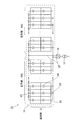
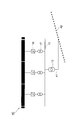
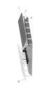
- FIG. 1A It is a figure which shows schematic structure of the solar energy power generation system which concerns on 1st Embodiment. It is a single wire connection diagram of the alternating current circuit part in FIG. 1A. It is a figure which shows the connection relation of the photovoltaic power generation unit of 1st Embodiment. It is a figure which shows the structure connected in series and parallel in FIG. 2A. It is a perspective view which shows the example of installation of the solar energy power generation system which concerns on 1st Embodiment. It is sectional drawing of FIG. 3A. It is a figure which shows schematic structure of the solar energy power generation system which concerns on 2nd Embodiment. It is a perspective view which shows the example of installation of the solar energy power generation system which concerns on 3rd Embodiment. It is a perspective view which shows the example of installation of the solar energy power generation system which concerns on 3rd Embodiment.
- FIG. 1A shows a schematic configuration of the photovoltaic power generation system according to the first embodiment of the present invention.
- the photovoltaic power generation system 10 includes a plurality of photovoltaic power generation units 11, a high voltage cable 12 that is attached to the plurality of photovoltaic power generation units 11, and is connected to each of the plurality of photovoltaic power generation units 11.
- a secondary transformer 13 that boosts the output AC current to an AC current of an appropriate voltage, and a special high-voltage transmission line 14 that transmits the AC current output from the secondary transformer 13 are provided.
- a plurality of units including a plurality of photovoltaic power generation units 11, high voltage cables 12, and secondary transformers 13 are connected to the special high voltage transmission line 14.
- the solar power generation unit 11 includes a solar cell unit 15, a conversion unit 16 that converts a direct current output from the solar cell unit 15 into an alternating current, and an alternating current output from the conversion unit into an alternating current of an appropriate voltage. And a primary transformer 17 for boosting the voltage.
- 40 photovoltaic power generation units 11 are provided.
- the solar power generation unit 11 is installed, for example, so that the longitudinal direction of the solar cell unit 15 is along the sound insulation wall of the highway.
- the solar cell unit 15 is an array unit in which high voltage output solar cell modules are connected in parallel, or strings in which high voltage output solar cell modules are connected in series are connected in parallel.
- the solar cell unit 15 will be described in detail separately.
- the conversion unit 16 is a PCS (power conditioner system) such as an inverter device, and converts a direct current output from the solar cell unit 15 into an alternating current.
- PCS power conditioner system
- the rated capacity of the PCS is assumed to be 250 kW and converted to AC400V.
- the primary transformer 17 has a rated capacity of 250 kVA, and boosts AC400V output from the converter 16 to AC6600V. And it is preferable to install the conversion part 16 and the primary transformer 17 adjacent in the same solar power generation unit 11.
- FIG. For example, if the conversion unit 16 and the primary transformer 17 are installed in one metal box, a cable of several tens of centimeters can be used, or can be provided without using a cable.
- a material of the metal box iron, aluminum, stainless steel or the like can be used. By shortening the installation distance between the converter 16 and the primary transformer 17, it is possible to reduce power loss in the cable connecting the converter 16 and the primary transformer 17.
- the high voltage cable 12 is a cable for connecting output power from the primary transformer 17 of each photovoltaic power generation unit 11 in parallel, and is arranged in parallel with the photovoltaic power generation unit 11 along the longitudinal direction of the solar cell unit 15.
- the secondary transformer 13 is installed at an intermediate point (intermediate point of the high voltage cable 12) of the 40 photovoltaic power generation units 11 provided side by side, and the high voltage (AC6600V in this case) output from the high voltage cable 12 is extra high.
- the voltage is boosted to 66 kV here.
- the special high voltage transmission line 14 is installed along, for example, a highway, and transmits the special high voltage output from each secondary transformer 13.
- a plurality of units including 40 photovoltaic power generation units 11, high voltage cables 12, and secondary transformers 13 are continuously installed, so that each secondary transformer 13 is continuously connected to a special height. It is connected to the voltage transmission line 14.
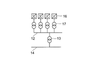
- FIG. 1B shows a single-line connection diagram of the AC circuit portion in the photovoltaic power generation system 10 having such a configuration.
- One feature is that one primary transformer 17 is installed for each converter 16.
- the special high voltage transmission line 14 is connected to the power company system, and the solar power generation system 10 generates power, the solar power generation When power is supplied from the system to the load and there is no power generation by the solar power generation system 10 (nighttime or the like), power may be supplied from the power company to supply power to the load.
- the solar cell unit 15 includes, for example, two strings of high voltage output solar cell modules (for example, thin film type solar cell modules) 20 having an output of 140 W connected in series, and 1000 strings are connected in parallel. It is a thing.
- the plus terminal of the terminal box 24 of one high voltage output solar cell module 20 and the other high voltage output solar cell module 20 is connected by a cable 22 to form a string.
- the pluses and minuses of the remaining two cables 21 and 25 are repeatedly connected via the connector 23 for parallel connection.
- a backflow prevention diode 26 is installed between the parallel connection connectors 23 that connect the pluses in parallel. The backflow prevention diode 26 has a role of preventing a current from flowing back when a part of the solar cell module 20 is shaded or the power generation amount of the module is insufficient due to some trouble.
- the solar power generation unit 11 including the solar cell unit 15 in which 2000 high-voltage output solar cell modules are connected in 2 series ⁇ 1000 parallel, the conversion unit 16, and the primary transformer 17 is formed. .
- connection can be performed only by the parallel connection connector 23, and a commonly used connection box or DC current collection box is not necessary.
- the solar power generation unit 11 as described above has a length of about 2.8 m ⁇ width of about 1000 m when a general module of length 1.4 m ⁇ width 1 m is used as the high voltage output solar cell module 20.
- the photovoltaic power generation system 10 in which 40 photovoltaic power generation units 11 are continuously installed in the lateral direction has a total length of 40 km and is arranged in parallel with the photovoltaic power generation system 10 (in other words, in the high voltage output solar cell module 20).
- the length of the high voltage cable 12 (which is arranged in parallel) is also 40 km. If the alternating current is 6600 V, the power loss is not a problem in practice even if it is passed through a 40 km cable.
- the power generation capacity of 10 MW is set, but the power generation capacity, that is, the number of parallel photovoltaic power generation units 11 may be increased up to the upper limit of the length of the high voltage cable 12.
- the upper limit value can be determined in accordance with the technical standards of electric facilities in consideration of power loss and the like, and there is no problem as long as it is normally up to 50 km.
- each is housed in a dedicated conduit 30 (see FIGS. 3A and 3B). If the road is overlaid, install it under the road, and if the road is overland, install it under the side. That is, the high voltage output solar cell module 20 is arranged in parallel with the high voltage cable 12 and the special high voltage transmission line 14.
- the special high voltage transmission line 14 is arranged along the road. For example, when three 40-km solar power generation systems 10 are continuously installed, the total high-voltage transmission line 14 has a total length of 120 km, and the generated power 30 MW flows there. The photovoltaic power generation system 10 does not need to be installed continuously. If the length of the 66 kV extra high-voltage transmission line 14 is within a practical distance range, the photovoltaic power generation system 10 is installed separately. It doesn't matter. Moreover, the upper limit in each of the length of the special high voltage power transmission line 14 and the number of installed photovoltaic power generation systems 10 (power generation capacity) is determined in accordance with the technical standards of the power equipment and the laws and regulations at the installation location.
- the solar cell unit 15 is installed on the mount 31 provided along the road.
- One pedestal 31 is provided with one array in which three strings are connected in parallel.
- the solar power generation system 40 As shown in FIG. 4, the solar power generation system 40 according to the second embodiment is connected to a 66 kV power system 42 using a connection cable 41. Since the configuration of the solar power generation system 40 is the same as that of the solar power generation system 10 of the first embodiment except that the extra high voltage transmission line 14 is omitted, detailed description thereof is omitted.
- the second embodiment can be implemented in the case where an electric power system exists near the expressway, and the case where power is supplied to a non-electrified village where infrastructure is not established is described in the first embodiment.
- the distribution line is connected to the special high-voltage transmission line 14, and it is installed and supplied to the demand area.
- the installation location of the secondary transformer 13 does not have to be an intermediate point of the photovoltaic power generation system 40. .
- the high-voltage cable 12 and the special high-voltage transmission line 14 are embedded under the highway or underground is described.
- the highway is elevated. Regardless of whether it is on land or not, it is possible to continuously install the gantry 31 having the same specification, and to continuously install the pipeline 30 and the like. Therefore, even if it is a land laying location, the construction for burying the pipe line 30 is not necessary, and the installation cost can be reduced.
- the mount 31 (not shown) is provided on the mount 31 of the photovoltaic power generation system 50, and the pipe line 30 is supported by the attachment.
- the pipe line 30 is not necessarily required, and the high voltage cable 12 and / or the special high voltage transmission line 14 may be directly supported by the attachment portion.
- the mount 31 for installing the solar cell unit 15 is laid on the highway.
- the configuration in which the pipe line 30 and the like are installed on the gantry 31 as in the third embodiment is effective. It is.
- the present invention is not limited to the above description, and various modifications can be made without departing from the spirit of the invention.
- the technical scope of the present invention also includes a configuration in which a storage battery is installed in a solar power generation system and a part of the electric power generated during the daytime is stored and consumed at night or when the sun is insufficient.
- Photovoltaic power generation system 11 Photovoltaic power generation unit 12 High voltage cable 13 Secondary transformer 14 Special high voltage transmission line (transmission line) DESCRIPTION OF SYMBOLS 15 Solar cell unit 16 Conversion part 17 Primary transformer 20 High voltage output solar cell module 31 Mounting stand
Landscapes
- Engineering & Computer Science (AREA)
- Power Engineering (AREA)
- Supply And Distribution Of Alternating Current (AREA)
- Charge And Discharge Circuits For Batteries Or The Like (AREA)
- Photovoltaic Devices (AREA)
Abstract
太陽電池ユニットを横方向に連続して長距離設置した場合にでも、太陽光発電ユニットのAC出力の接続ケーブルでの電力損失を低減できる太陽光発電システムを提供することを目的とする。そのため、太陽光発電システムは、高電圧出力太陽電池モジュールを並列接続した、又は高電圧出力太陽電池モジュールを直列接続したストリングスを並列接続した太陽電池ユニットと、太陽電池ユニットから出力される直流電流を交流電流に変換する変換部と、変換部から出力された交流電流を適当な電圧の交流電流に昇圧する一次変圧器とを有する太陽光発電ユニットを複数備え、複数の太陽光発電ユニットに併設され、複数の太陽光発電ユニットそれぞれが接続される高電圧ケーブルを備える構成とする。
Description
本発明は、太陽光発電システムに関し、特に複数の太陽電池モジュールによって構成され、送電線に沿って設置して発電を行うタイプの太陽光発電システム及びその送電系統における変電設備の構成に関する。
太陽光発電システムは、一つの土地に複数の太陽電池モジュールをアレイ状に設置して発電を行うタイプが一般的である。近年、この太陽電池アレイを広大な土地に大量に敷き詰めた大規模な発電システムが注目されており、MW(メガワット)級の発電システムも世界各地で設置事例がある。
このように、ひとまとまりの土地に複数の太陽電池モジュールをアレイ状に設置して発電を行う場合、大規模発電になるほど広大な土地が必要となり、土地の確保が困難になる。例えば、10MW程度のシステムの場合、おおよそ400m×700mという広大な土地が必要である。
これに対して、複数の太陽電池モジュールによって構成される太陽電池ユニットを高速道路などに沿って設置して発電を行うタイプの太陽光発電システムも提案されている。例えば、特許文献1には、PCS(パワーコンディショナシステム)の出力を既設の道路照明灯の為の配電線に接続する構成が開示されている。
また特許文献2には、横方向に細長く設置するアレイ構造において太陽電池ユニットとPCSを接続するケーブルが長くなることによる電力損失の低減を図ることができる太陽光発電システムが開示されている。このシステム構成によると、高電圧出力太陽電池モジュールを並列接続した太陽電池ユニットを用いることにより、接続ケーブルの引回しを少なくでき、ケーブルの電力損失の低減が図られている。
特許文献2の太陽光発電システムは、太陽電池ユニットと、太陽電池ユニットから出力される直流電流を交流電流に変換するPCSと、表示灯等の負荷とを有する太陽光発電ユニットを複数備えている。複数の太陽光発電ユニットは太陽電池ユニットの長手方向が例えば高速道路の遮音壁に沿って配置される。
この太陽光発電システムは、複数の太陽電池ユニットに対して1つずつ配置されているPCSからのAC400V出力をPCS出力ケーブルを用いて並列接続している。また、PCS出力ケーブル側からの電圧を高電圧に変圧して高電圧送電線に供給し、逆に、高電圧送電線からの電圧をAC400Vに変圧してPCS出力ケーブルへ供給する、定格容量150kVAの変圧器を備えている。ここでの高電圧送電線は、例えば、AC6600V又はAC22kVのような遠隔地への送電を目的としている。
また、特許文献2の太陽光発電システムにおける各太陽電池ユニットは、開放電圧240V以上の高電圧出力薄膜太陽電池モジュールを75個備え、これらを75並列で接続し、高電圧出力薄膜太陽電池モジュールの並列方向を太陽電池ユニットの長手方向としている。そして、太陽電池ユニットとPCSとがPCS入力ケーブルで接続されている。
このような構成の場合、各太陽光発電ユニットの発電容量は140Wを75個用いるため約10kWとなる。各PCSの定格容量も10kWである。さらに、各太陽光発電ユニットを並列接続した後に150kVAの変圧器へ入力しているため、太陽光発電ユニットは合計15個まで並列接続されている。この場合、太陽電池ユニットの全長は75mとなり、各PCSの設置間隔も75mとなる。仮にこれら15個の太陽光発電ユニットの中央に変圧器を設置した場合、最も外側にあるPCSから変圧器までの距離は約350mとなる。AC400Vであれば、この程度の距離に対する送電ロスは特に問題にならない。
ところで、上述したようにMW級の発電システムの設置事例があり、高速道路に設置する太陽光発電システムについても同様に大容量化が検討される方向にある。もし、特許文献2のような構成で、例えば10MWの発電システムを構築しようとすると、10kWのPCSを10kW毎に1つずつ並べていくのではコストアップに繋がるため、近年の動向を鑑みると250kWのPCSを使用するのが妥当である。よって、太陽電池ユニットも同様に250kWになるように配置することになる。
ここで、250kWのPCSの仕様として140Wの薄膜太陽電池モジュールを2個直列接続したストリングスを入力するような仕様のものを選定してシステムを構築すると、2直列×1000並列の太陽電池ユニットとなり、1000個分のモジュールが横一列に設置されるために、太陽電池ユニットの全長は1000mになる。よって、PCSの設置間隔も同様に1000mになる。
次に、これらのPCSを特許文献2と同様に複数個並列接続した場合、PCSの個数×1000mの並列接続となる。よって、PCS出力ケーブルの全長がかなりの長距離になり、電力損失が大きくなるという課題が生じる。なお、10MWの発電システムを系統連系する場合は特許文献2のように6600Vでなく特別高電圧と連系する必要があるため、66kV等の超高電圧と連系させる必要がある。例えば、PCSの並列数を4個にして一次変圧器で一旦6600Vに昇圧し、さらにそれらを10並列した後に変圧器にて66kVに昇圧させるような構成を考えた場合、1MW分の発電システムの中央に一次変圧器を設置したとして、最も外側のPCSから一次変圧器までの距離は2000mになり、これにAC400Vを供給すると電力損失を無視できなくなる。なお、AC400Vで送電できる距離はせいぜい500mまでであると考えられる。
本発明は、太陽電池ユニットを横方向に連続して長距離設置した場合にでも、太陽光発電ユニットのAC出力の接続ケーブルでの電力損失を低減できる太陽光発電システムを提供することを目的とする。
上記目的を達成するために本発明は、高電圧出力太陽電池モジュールを並列接続した、又は前記高電圧出力太陽電池モジュールを直列接続したストリングスを並列接続した太陽電池ユニットと、前記太陽電池ユニットから出力される直流電流を交流電流に変換する変換部と、前記変換部から出力された交流電流を適当な電圧の交流電流に昇圧する一次変圧器とを有する太陽光発電ユニットを複数備え、複数の前記太陽光発電ユニットに併設され、複数の前記太陽光発電ユニットそれぞれが接続される高電圧ケーブルを備えることを特徴とする太陽光発電システムとする。
この構成によると、変換部と一次変圧器の設置距離を短くできる。
上記の太陽光発電システムを高速道路等に設置する場合、前記高電圧出力太陽電池モジュールを前記高電圧ケーブルと並設することが好ましい。
また上記の太陽光発電システムにおいて、前記高電圧出力太陽電池モジュールを並設して並列接続することが好ましい。このように配置することで、並列接続用コネクタだけで太陽電池ユニットの並列接続が完成し、太陽電池ユニットの片端にあるケーブルを変換部に接続するだけで済むため、従来大規模太陽光発電システムで必要であった接続箱やDC集電箱を省略できる。
また上記の太陽光発電システムにおいて、前記変換部と前記一次変圧器を隣接して設置することが好ましい。
また上記の太陽光発電システムにおいて、前記変換部と前記一次変圧器とを金属箱内に併設することが好ましい。
また上記の太陽光発電システムにおいて、前記高電圧ケーブルから出力される交流電流を適当な電圧の交流電流に昇圧する二次変圧器を備えることが好ましい。
また上記の太陽光発電システムにおいて、前記二次変圧器から出力される交流電流を送電する送電線を備えることが好ましい。
また上記の太陽光発電システムにおいて、前記高電圧出力太陽電池モジュールを前記送電線と並設することが好ましい。これにより、送電線の長さが必要最低限となり、コストアップを抑制できる。
また上記の太陽光発電システムにおいて、前記太陽電池ユニットを設置する架台を備えてもよい。また、前記架台が取付部を有し、前記高電圧ケーブル及び/又は前記送電線を前記取付部で支持するようにしてもよい。さらに、前記高電圧ケーブル及び/又は前記送電線が管路に収納された状態で前記取付部で支持されるようにしてもよい。これにより、設置する道路が高架であっても陸上であっても高電圧ケーブル及び/又は送電線の設置手法が同じとなり、さらに長さを抑制できる。
本発明によると、変換部と一次変圧器の設置距離を短くできるので、MW級の超大規模太陽光発電システムとして太陽電池ユニットを横方向に連続して長距離設置した場合にでも、変換部と一次変圧器を繋ぐケーブルにおける電力損失を低減できる。したがって、効率の良い発電設備を提供できる。
また本発明によると、インフラが整備されていない無電化村等へ電力供給することも可能である。さらに、本発明の太陽光発電システムを高速道路に設置することにより、広大なまとまった土地を使う必要がなく、既設の高速道路への設置も容易であるため、設置場所の確保も特に必要としない。
本発明の第1実施形態に係る太陽光発電システムの概略構成を図1Aに示す。ここでは太陽光発電システムの発電容量が10MWの場合について説明する。太陽光発電システム10は、複数の太陽光発電ユニット11と、複数の太陽光発電ユニット11に併設され、複数の太陽光発電ユニット11それぞれが接続される高電圧ケーブル12と、高電圧ケーブル12から出力される交流電流を適当な電圧の交流電流に昇圧する二次変圧器13と、二次変圧器13から出力される交流電流を送電する特別高電圧送電線14とを備えている。実際には、特別高電圧送電線14に、複数の太陽光発電ユニット11、高電圧ケーブル12、二次変圧器13からなるユニットが複数接続されている。
太陽光発電ユニット11は、太陽電池ユニット15と、太陽電池ユニット15から出力される直流電流を交流電流に変換する変換部16と、変換部から出力された交流電流を適当な電圧の交流電流に昇圧する一次変圧器17とを有する。ここでは太陽光発電ユニット11を40個備えている。太陽光発電ユニット11は、例えば、太陽電池ユニット15の長手方向が高速道路の遮音壁に沿うように設置する。
太陽電池ユニット15は、高電圧出力太陽電池モジュールを並列接続した、又は高電圧出力太陽電池モジュールを直列接続したストリングスを並列接続したアレイユニットである。太陽電池ユニット15については別途詳しく説明する。
変換部16は、インバータ装置等のPCS(パワーコンディショナシステム)であり、太陽電池ユニット15から出力される直流電流を交流電流に変換する。ここではPCSの定格容量を250kWとし、AC400Vに変換するものとする。
一次変圧器17は、ここでは定格容量を250kVAとし、変換部16から出力されるAC400VをAC6600Vに昇圧する。そして、同じ太陽光発電ユニット11内で変換部16と一次変圧器17とは隣接して設置することが好ましい。例えば、変換部16と一次変圧器17とを1つの金属箱内に設置すれば、数十cmのケーブルを用いるか、又はケーブルを用いないで併設できる。金属箱の材料としては鉄、アルミニウム、ステンレス等を用いることができる。変換部16と一次変圧器17の設置距離を短くすることで、変換部16と一次変圧器17を繋ぐケーブルにおける電力損失を低減できる。
高電圧ケーブル12は、各太陽光発電ユニット11の一次変圧器17からの出力電力を並列接続するケーブルであり、太陽電池ユニット15の長手方向に沿って太陽光発電ユニット11に並設される。
二次変圧器13は、40個併設した太陽光発電ユニット11の中間点(高電圧ケーブル12の中間点)に設置され、高電圧ケーブル12から出力される高電圧(ここではAC6600V)を特別高電圧(ここでは66kV)へ昇圧する。
特別高電圧送電線14は、例えば高速道路に沿って設置されており、各二次変圧器13から出力される特別高電圧を送電する。ここでは40個の太陽光発電ユニット11と高電圧ケーブル12と二次変圧器13とからなるユニットをさらに複数連続して設置しているので、各々の二次変圧器13が連続して特別高電圧送電線14に接続されている。
このような構成の太陽光発電システム10における交流回路部分の単線結線図を図1Bに示す。一つの特徴としては、各変換部16に対して一つずつ一次変圧器17を設置していることが挙げられる。
なお上記の実施形態において、高速道路に沿って照明灯などの負荷を設置し、特別高電圧送電線14を電力会社の系統と接続し、太陽光発電システム10の発電があるときは太陽光発電システムから負荷へ電力供給を行い、太陽光発電システム10の発電が無いとき(夜間等)は、電力会社から電力供給を受けて負荷に電力供給を行う構成としてもよい。
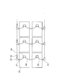
次に、太陽電池ユニット15の構成について図2A、図2Bを参照して説明する。図2Aに示すように、太陽電池ユニット15は、例えば出力140Wの高電圧出力太陽電池モジュール(例えば、薄膜型太陽電池モジュール)20を2つ直列接続してストリングスとし、このストリングスを1000個並列接続したものである。
また図2Bに示すように、高電圧出力太陽電池モジュール20を2つずつ直列接続するために、一方の高電圧出力太陽電池モジュール20の端子ボックス24のプラス端子と他方の高電圧出力太陽電池モジュール20の端子ボックス24のマイナス端子とをケーブル22で接続してストリングスとする。そして、このストリングスを順次並列に接続するために、残った2本のケーブル21、25のプラス同士、マイナス同士を並列接続用コネクタ23を介して接続を繰り返す。プラス同士を並列接続する並列接続用コネクタ23間には逆流防止ダイオード26が設置されている。この逆流防止ダイオード26には、太陽電池モジュール20の一部に影がかかったり、何らかの不具合でそのモジュールの発電量が不足した場合に電流が逆流することを防止する役割がある。
そして、図2Aに示すような2直列のストリングスを500セットずつ横方向に連続して並設して並列接続したものを2つ設置し、それぞれから変換部16の入力端子へケーブル27により直流電流を入力する。このようにして、2000個の高電圧出力太陽電池モジュールを2直列×1000並列に接続させた太陽電池ユニット15と変換部16と一次変圧器17とを備えた太陽光発電ユニット11が形成される。
このような接続構造とすることにより、並列接続を並列接続用コネクタ23だけで行うことができ、一般的に用いられている接続箱やDC集電箱は必要ない。
以上説明したような太陽光発電ユニット11は、高電圧出力太陽電池モジュール20として一般的な縦1.4m×横1mのモジュールを用いた場合、縦約2.8m×横約1000mとなる。この太陽光発電ユニット11を横方向に40個連続して設置した太陽光発電システム10は全長40kmであり、太陽光発電システム10に並設される(言い換えると、高電圧出力太陽電池モジュール20に並設される)高電圧ケーブル12の長さも40kmである。6600Vの交流電流であれば、40kmのケーブルに流しても電力損失は実用上問題とならない程度である。
本実施形態では10MWの発電容量を設定したが、高電圧ケーブル12の長さの上限値までは発電容量、すなわち太陽光発電ユニット11の並列数を増やしても構わない。この上限値については電力損失等を考慮して、電気設備の技術基準などに従って決定でき、通常50kmまでであれば問題ない。
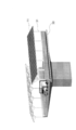
高電圧ケーブル12及び特別高電圧送電線14を高速道路に設置する場合、各々を専用の管路30(図3A、図3B参照)の内部へ収納した上で、図3A、図3Bに示すように道路が高架布設の場合は道路の下部へ、道路が陸上布設の場合は脇側の地下へそれぞれ設置する。すなわち、高電圧出力太陽電池モジュール20は高電圧ケーブル12及び特別高電圧送電線14に並設される。
特別高電圧送電線14は、道路に沿って配置されており、例えば40kmの太陽光発電システム10が3つ連続して設置されている場合には全長120kmとなり、発電電力30MWがここを流れる。なお、太陽光発電システム10は連続して設置する必要はなく、66kVの特別高電圧送電線14の長さが実用上問題無い距離の範囲内となるようにすれば、各々を離して設置しても構わない。また、特別高電圧送電線14の長さ及び太陽光発電システム10の設置個数(発電容量)のそれぞれにおける上限値は、電力設備の技術基準及びその設置場所における法令などに従って決定される。
また図3では、太陽電池ユニット15を道路に沿って設けられた架台31に設置している。1つの架台31にはストリングスを3並列に接続したアレイが1つ設置される。
次に、第2実施形態に係る太陽光発電システムについて説明する。第1実施形態の太陽光発電システム10では、高速道路に沿って特別高圧送電線14を設置して発電電力を集める場合について説明したが、第2実施形態ではこの特別高圧送電線14を設置せずに二次変圧器13からの出力電力を直接、電力会社等の電力系統へ連系させるものとする。
図4に示すように、第2実施形態に係る太陽光発電システム40は連系ケーブル41を用いて66kVの電力系統42へ接続している。太陽光発電システム40の構成については、特別高電圧送電線14を省くこと以外は第1実施形態の太陽光発電システム10と同様であるため、詳細な説明は省略する。
なお、第2実施形態は高速道路の近くに電力系統が存在する場合に対して実施可能であり、インフラが整備されていない無電化村等へ電力供給する場合は前述の第1実施形態で説明した特別高圧送電線14に配電線を接続し、それを需要地まで設置して供給することになる。
第2実施形態の場合、電力系統へ接続可能な場所に二次変圧器13を設置することが好ましいため、二次変圧器13の設置箇所は太陽光発電システム40の中間点である必要はない。
次に、第3実施形態に係る太陽光発電システムについて説明する。第1実施形態では、高電圧ケーブル12及び特別高電圧送電線14を高速道路の高架下又は地下埋設させる場合について説明したが、これを架台31へ設置させるようにすれば、高速道路が高架であれ陸上であれ、同一仕様の架台31を連続的に設置して、これに管路30等を連続して設置することが可能となる。よって、陸上布設箇所であっても管路30を埋設するための工事も必要なく、設置コストの削減が可能となる。
図5A、図5Bに示すように、太陽光発電システム50の架台31には取付部(不図示)が設けられ、管路30を該取付部で支持する構造になっている。なお、管路30は必ずしも必要ではなく、高電圧ケーブル12及び/又は特別高電圧送電線14を取付部で直接支持するようにしてもよい。
なお、第3実施形態では太陽電池ユニット15を設置するための架台31を高速道路に布設することが前提である。世界的に高速道路には側壁のようなものがない場合が多く、架台31の設置が必要な場合が多いため、第3実施形態のような架台31へ管路30等を設置する構成は有効である。
本発明は上記の説明に限定されるものではなく、発明の主旨を逸脱しない範囲で種々の変更を加えての実施が可能である。例えば、太陽光発電システムの中に蓄電池を設置して昼間発電した電力の一部を貯蓄し、夜間や日照不足時にこれを消費するような構成も本発明の技術範囲に含まれる。
10、40、50 太陽光発電システム
11 太陽光発電ユニット
12 高電圧ケーブル
13 二次変圧器
14 特別高電圧送電線(送電線)
15 太陽電池ユニット
16 変換部
17 一次変圧器
20 高電圧出力太陽電池モジュール
31 架台
11 太陽光発電ユニット
12 高電圧ケーブル
13 二次変圧器
14 特別高電圧送電線(送電線)
15 太陽電池ユニット
16 変換部
17 一次変圧器
20 高電圧出力太陽電池モジュール
31 架台
Claims (11)
- 高電圧出力太陽電池モジュールを並列接続した、又は前記高電圧出力太陽電池モジュールを直列接続したストリングスを並列接続した太陽電池ユニットと、前記太陽電池ユニットから出力される直流電流を交流電流に変換する変換部と、前記変換部から出力された交流電流を適当な電圧の交流電流に昇圧する一次変圧器とを有する太陽光発電ユニットを複数備え、
複数の前記太陽光発電ユニットに併設され、複数の前記太陽光発電ユニットそれぞれが接続される高電圧ケーブルを備えることを特徴とする太陽光発電システム。 - 前記高電圧出力太陽電池モジュールを前記高電圧ケーブルと並設することを特徴とする請求項1記載の太陽光発電システム。
- 前記高電圧出力太陽電池モジュールを並設して並列接続することを特徴とする請求項1又は2記載の太陽光発電システム。
- 前記変換部と前記一次変圧器を隣接して設置することを特徴とする請求項1~3の何れかに記載の太陽光発電システム。
- 前記変換部と前記一次変圧器とを金属箱内に併設することを特徴とする請求項1~4の何れかに記載の太陽光発電システム。
- 前記高電圧ケーブルから出力される交流電流を適当な電圧の交流電流に昇圧する二次変圧器を備えることを特徴とする請求項1~5の何れかに記載の太陽光発電システム。
- 前記二次変圧器から出力される交流電流を送電する送電線を備えることを特徴とする請求項6記載の太陽光発電システム。
- 前記高電圧出力太陽電池モジュールを前記送電線と並設することを特徴とする請求項7記載の太陽光発電システム。
- 前記太陽電池ユニットを設置する架台を備えたことを特徴とする請求項1~8の何れかに記載の太陽光発電システム。
- 前記架台が取付部を有し、前記高電圧ケーブル及び/又は前記送電線を前記取付部で支持することを特徴とする請求項9記載の太陽光発電システム。
- 前記高電圧ケーブル及び/又は前記送電線が管路に収納された状態で前記取付部で支持されていることを特徴とする請求項10記載の太陽光発電システム。
Applications Claiming Priority (2)
| Application Number | Priority Date | Filing Date | Title |
|---|---|---|---|
| JP2011000586A JP2012143102A (ja) | 2011-01-05 | 2011-01-05 | 太陽光発電システム |
| JP2011-000586 | 2011-01-05 |
Publications (1)
| Publication Number | Publication Date |
|---|---|
| WO2012093584A1 true WO2012093584A1 (ja) | 2012-07-12 |
Family
ID=46457444
Family Applications (1)
| Application Number | Title | Priority Date | Filing Date |
|---|---|---|---|
| PCT/JP2011/079503 Ceased WO2012093584A1 (ja) | 2011-01-05 | 2011-12-20 | 太陽光発電システム |
Country Status (2)
| Country | Link |
|---|---|
| JP (1) | JP2012143102A (ja) |
| WO (1) | WO2012093584A1 (ja) |
Families Citing this family (2)
| Publication number | Priority date | Publication date | Assignee | Title |
|---|---|---|---|---|
| JP2014158420A (ja) * | 2012-10-31 | 2014-08-28 | Hitachi Industrial Equipment Systems Co Ltd | 災害時の電力系統の異常事態に対応可能な電力買取システム用系統連系装置、及び当該電力買取システム用系統連系装置を用いた災害等の緊急避難時における電力の緊急出力方法 |
| CN103972923A (zh) * | 2014-04-12 | 2014-08-06 | 张祈泰 | 一种大型太阳能光伏并网发电系统多组合装置 |
Citations (3)
| Publication number | Priority date | Publication date | Assignee | Title |
|---|---|---|---|---|
| JP2002081765A (ja) * | 2000-08-31 | 2002-03-22 | Sekisui Chem Co Ltd | 太陽エネルギー利用システムの配線配管の保護構造 |
| JP2010213384A (ja) * | 2009-03-06 | 2010-09-24 | Chugoku Electric Power Co Inc:The | 分散型電源システム |
| JP2010279133A (ja) * | 2009-05-27 | 2010-12-09 | Ntt Facilities Inc | 太陽光発電システムにおけるパワーコンディショナーの制御方法及び装置 |
Family Cites Families (2)
| Publication number | Priority date | Publication date | Assignee | Title |
|---|---|---|---|---|
| JPH08126224A (ja) * | 1994-10-20 | 1996-05-17 | Canon Inc | 太陽光発電システム |
| JP2010098797A (ja) * | 2008-10-14 | 2010-04-30 | Sharp Corp | 太陽光発電システム |
-
2011
- 2011-01-05 JP JP2011000586A patent/JP2012143102A/ja active Pending
- 2011-12-20 WO PCT/JP2011/079503 patent/WO2012093584A1/ja not_active Ceased
Patent Citations (3)
| Publication number | Priority date | Publication date | Assignee | Title |
|---|---|---|---|---|
| JP2002081765A (ja) * | 2000-08-31 | 2002-03-22 | Sekisui Chem Co Ltd | 太陽エネルギー利用システムの配線配管の保護構造 |
| JP2010213384A (ja) * | 2009-03-06 | 2010-09-24 | Chugoku Electric Power Co Inc:The | 分散型電源システム |
| JP2010279133A (ja) * | 2009-05-27 | 2010-12-09 | Ntt Facilities Inc | 太陽光発電システムにおけるパワーコンディショナーの制御方法及び装置 |
Also Published As
| Publication number | Publication date |
|---|---|
| JP2012143102A (ja) | 2012-07-26 |
Similar Documents
| Publication | Publication Date | Title |
|---|---|---|
| US9197069B2 (en) | Power transmission systems | |
| EP2602903A1 (en) | Power management apparatus and method of operating the same | |
| JP2010213384A (ja) | 分散型電源システム | |
| WO2011033308A2 (en) | A power collection and distribution system | |
| JP2012515519A (ja) | 電力供給システムおよびそのための太陽電池装置 | |
| JP2015080404A (ja) | 洋上入力端と陸上出力端を有する海底交流送電ケーブルにおける無効電力補償 | |
| US20240128761A1 (en) | Docking stations for mobile energy storage units | |
| US20140265607A1 (en) | System And Method For Loop-Based Direct Current Electrical Power Transmission System | |
| CN114400603A (zh) | 高压输电和光伏发电的一体化系统及一体化设计方法 | |
| WO2012117751A1 (ja) | 発電システム | |
| JP4075787B2 (ja) | 送配電システム、非常用電気機器および送配電システムの運用方法 | |
| ITPI20110142A1 (it) | Apparato di trasformazione di energia prodotta da fonti rinnovabili e metodo di gestione relativo | |
| WO2012093584A1 (ja) | 太陽光発電システム | |
| JP2013013174A (ja) | 電力供給システム | |
| KR20170067127A (ko) | 수상태양광발전시스템 | |
| JP7370850B2 (ja) | 電力供給システムおよび受変電設備 | |
| US9306414B2 (en) | Medium voltage power transmission line alternative | |
| CN110661317B (zh) | 一种led市政路灯和直流充电桩一体化设备 | |
| JP6411114B2 (ja) | 太陽光発電設備システム | |
| Rasel et al. | Electricity extraction from unoccupied land of substation | |
| WO2009100392A2 (en) | Methods and apparatuses related to energy production and transmission | |
| Sankar et al. | Low cost electrification using solar energy-A field work | |
| CN201426099Y (zh) | 一种风光互补独立电源 | |
| JP2010098797A (ja) | 太陽光発電システム | |
| JP2012217255A (ja) | 配電システム |
Legal Events
| Date | Code | Title | Description |
|---|---|---|---|
| 121 | Ep: the epo has been informed by wipo that ep was designated in this application |
Ref document number: 11855110 Country of ref document: EP Kind code of ref document: A1 |
|
| NENP | Non-entry into the national phase |
Ref country code: DE |
|
| 122 | Ep: pct application non-entry in european phase |
Ref document number: 11855110 Country of ref document: EP Kind code of ref document: A1 |