WO2012090765A1 - Magnetic body - Google Patents
Magnetic body Download PDFInfo
- Publication number
- WO2012090765A1 WO2012090765A1 PCT/JP2011/079401 JP2011079401W WO2012090765A1 WO 2012090765 A1 WO2012090765 A1 WO 2012090765A1 JP 2011079401 W JP2011079401 W JP 2011079401W WO 2012090765 A1 WO2012090765 A1 WO 2012090765A1
- Authority
- WO
- WIPO (PCT)
- Prior art keywords
- magnetic
- magnet
- analysis
- magnetic field
- hcj
- Prior art date
Links
Images


Classifications
-
- H—ELECTRICITY
- H01—ELECTRIC ELEMENTS
- H01F—MAGNETS; INDUCTANCES; TRANSFORMERS; SELECTION OF MATERIALS FOR THEIR MAGNETIC PROPERTIES
- H01F7/00—Magnets
- H01F7/02—Permanent magnets [PM]
- H01F7/0205—Magnetic circuits with PM in general
- H01F7/0226—PM with variable field strength
-
- B—PERFORMING OPERATIONS; TRANSPORTING
- B22—CASTING; POWDER METALLURGY
- B22F—WORKING METALLIC POWDER; MANUFACTURE OF ARTICLES FROM METALLIC POWDER; MAKING METALLIC POWDER; APPARATUS OR DEVICES SPECIALLY ADAPTED FOR METALLIC POWDER
- B22F3/00—Manufacture of workpieces or articles from metallic powder characterised by the manner of compacting or sintering; Apparatus specially adapted therefor ; Presses and furnaces
- B22F3/10—Sintering only
-
- B—PERFORMING OPERATIONS; TRANSPORTING
- B22—CASTING; POWDER METALLURGY
- B22F—WORKING METALLIC POWDER; MANUFACTURE OF ARTICLES FROM METALLIC POWDER; MAKING METALLIC POWDER; APPARATUS OR DEVICES SPECIALLY ADAPTED FOR METALLIC POWDER
- B22F9/00—Making metallic powder or suspensions thereof
- B22F9/02—Making metallic powder or suspensions thereof using physical processes
- B22F9/023—Hydrogen absorption
-
- C—CHEMISTRY; METALLURGY
- C22—METALLURGY; FERROUS OR NON-FERROUS ALLOYS; TREATMENT OF ALLOYS OR NON-FERROUS METALS
- C22C—ALLOYS
- C22C1/00—Making non-ferrous alloys
- C22C1/02—Making non-ferrous alloys by melting
-
- C—CHEMISTRY; METALLURGY
- C22—METALLURGY; FERROUS OR NON-FERROUS ALLOYS; TREATMENT OF ALLOYS OR NON-FERROUS METALS
- C22C—ALLOYS
- C22C33/00—Making ferrous alloys
- C22C33/02—Making ferrous alloys by powder metallurgy
- C22C33/0257—Making ferrous alloys by powder metallurgy characterised by the range of the alloying elements
- C22C33/0278—Making ferrous alloys by powder metallurgy characterised by the range of the alloying elements with at least one alloying element having a minimum content above 5%
-
- C—CHEMISTRY; METALLURGY
- C22—METALLURGY; FERROUS OR NON-FERROUS ALLOYS; TREATMENT OF ALLOYS OR NON-FERROUS METALS
- C22C—ALLOYS
- C22C38/00—Ferrous alloys, e.g. steel alloys
- C22C38/002—Ferrous alloys, e.g. steel alloys containing In, Mg, or other elements not provided for in one single group C22C38/001 - C22C38/60
-
- C—CHEMISTRY; METALLURGY
- C22—METALLURGY; FERROUS OR NON-FERROUS ALLOYS; TREATMENT OF ALLOYS OR NON-FERROUS METALS
- C22C—ALLOYS
- C22C38/00—Ferrous alloys, e.g. steel alloys
- C22C38/005—Ferrous alloys, e.g. steel alloys containing rare earths, i.e. Sc, Y, Lanthanides
-
- C—CHEMISTRY; METALLURGY
- C22—METALLURGY; FERROUS OR NON-FERROUS ALLOYS; TREATMENT OF ALLOYS OR NON-FERROUS METALS
- C22C—ALLOYS
- C22C38/00—Ferrous alloys, e.g. steel alloys
- C22C38/06—Ferrous alloys, e.g. steel alloys containing aluminium
-
- C—CHEMISTRY; METALLURGY
- C22—METALLURGY; FERROUS OR NON-FERROUS ALLOYS; TREATMENT OF ALLOYS OR NON-FERROUS METALS
- C22C—ALLOYS
- C22C38/00—Ferrous alloys, e.g. steel alloys
- C22C38/10—Ferrous alloys, e.g. steel alloys containing cobalt
-
- C—CHEMISTRY; METALLURGY
- C22—METALLURGY; FERROUS OR NON-FERROUS ALLOYS; TREATMENT OF ALLOYS OR NON-FERROUS METALS
- C22C—ALLOYS
- C22C38/00—Ferrous alloys, e.g. steel alloys
- C22C38/12—Ferrous alloys, e.g. steel alloys containing tungsten, tantalum, molybdenum, vanadium, or niobium
-
- C—CHEMISTRY; METALLURGY
- C22—METALLURGY; FERROUS OR NON-FERROUS ALLOYS; TREATMENT OF ALLOYS OR NON-FERROUS METALS
- C22C—ALLOYS
- C22C38/00—Ferrous alloys, e.g. steel alloys
- C22C38/16—Ferrous alloys, e.g. steel alloys containing copper
-
- H—ELECTRICITY
- H01—ELECTRIC ELEMENTS
- H01F—MAGNETS; INDUCTANCES; TRANSFORMERS; SELECTION OF MATERIALS FOR THEIR MAGNETIC PROPERTIES
- H01F1/00—Magnets or magnetic bodies characterised by the magnetic materials therefor; Selection of materials for their magnetic properties
- H01F1/01—Magnets or magnetic bodies characterised by the magnetic materials therefor; Selection of materials for their magnetic properties of inorganic materials
- H01F1/03—Magnets or magnetic bodies characterised by the magnetic materials therefor; Selection of materials for their magnetic properties of inorganic materials characterised by their coercivity
- H01F1/032—Magnets or magnetic bodies characterised by the magnetic materials therefor; Selection of materials for their magnetic properties of inorganic materials characterised by their coercivity of hard-magnetic materials
- H01F1/04—Magnets or magnetic bodies characterised by the magnetic materials therefor; Selection of materials for their magnetic properties of inorganic materials characterised by their coercivity of hard-magnetic materials metals or alloys
- H01F1/047—Alloys characterised by their composition
- H01F1/053—Alloys characterised by their composition containing rare earth metals
- H01F1/055—Alloys characterised by their composition containing rare earth metals and magnetic transition metals, e.g. SmCo5
- H01F1/057—Alloys characterised by their composition containing rare earth metals and magnetic transition metals, e.g. SmCo5 and IIIa elements, e.g. Nd2Fe14B
- H01F1/0571—Alloys characterised by their composition containing rare earth metals and magnetic transition metals, e.g. SmCo5 and IIIa elements, e.g. Nd2Fe14B in the form of particles, e.g. rapid quenched powders or ribbon flakes
- H01F1/0575—Alloys characterised by their composition containing rare earth metals and magnetic transition metals, e.g. SmCo5 and IIIa elements, e.g. Nd2Fe14B in the form of particles, e.g. rapid quenched powders or ribbon flakes pressed, sintered or bonded together
Definitions
- the present invention relates to a magnetic material.
- variable magnetic flux motor using a magnet (variable magnetic magnet) whose magnetic force reversibly changes by applying a magnetic field from the outside has been developed.
- the reduction in the efficiency of the conventional motor can be suppressed by reducing the magnetic force of the variable magnetic magnet in the middle / high speed range and light load.
- a fixed magnet having a constant magnetic force such as an Nd—Fe—B rare earth magnet (for example, Nd 2 Fe 14 B) and a variable magnetic magnet such as Sm 2 Co 17 are used. Used together.
- the residual magnetic flux density Br of the fixed magnet Nd 2 Fe 14 B is about 13 kG and the Br of the variable magnetic magnet Sm 2 Co 17 is about 10 kG.
- Nd—Fe—B rare earth magnet which has been conventionally used as a fixed magnet, as a variable magnetic magnet.
- the magnetization (coercive force) mechanism of Nd-Fe-B based rare earth magnet because a nucleation type, the magnetic force change or the magnetization reversal requires a large external magnetic field than in the case of Sm 2 Co 17.
- a large external magnetic field requires a large magnetizing current, the efficiency of the motor is lowered and control by a magnetic circuit is not easy. Because of these problems, it is not easy to put the Nd—Fe—B rare earth magnet into practical use as a variable magnetic force magnet.
- the magnetization mechanism is a pinning type magnetization mechanism such as Sm 2 Co 17 or a single domain particle type magnetization mechanism such as a ferrite magnet. Must be realized in the Nd—Fe—B rare earth magnet.
- the present invention has been made in view of such problems of the prior art, and provides a magnetic body having a high residual magnetic flux density and capable of reversibly changing the magnetic force with a small external magnetic field. For the purpose.
- the magnetic body according to the present invention has a residual magnetic flux density Br of 11 kG or more, a coercive force HcJ of 5 kOe or less, and an external magnetic field required to make the residual magnetic flux density Br 0. 10 HcJ or less.
- the magnetic material according to the present invention is suitable as a variable magnetic magnet for a variable magnetic flux motor because it has a high residual magnetic flux density and its magnetic force (magnetic flux density) reversibly changes due to a small external magnetic field.
- the magnetic material according to the present invention preferably contains a rare earth element R, a transition metal element T, and boron B. That is, the magnetic body according to the present invention preferably has a composition of an RTB rare earth magnet. In the magnetic body having such a composition, the effect of the present invention becomes remarkable, and it is possible to reduce the cost because it does not require expensive and unstable supply Co unlike the SmCo magnet. .
- the crystal particle diameter of the magnetic material according to the present invention is preferably 1 ⁇ m or less. Thereby, the effect of the present invention becomes remarkable.
- the present invention it is possible to provide a magnetic body having a high residual magnetic flux density and capable of reversibly changing the magnetic force with a small external magnetic field.
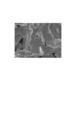
- FIG. 1a is a photograph of a fractured surface of a magnetic material of Example 4 of the present invention taken by a scanning electron microscope (SEM), and FIG. 1b is a scanning transmission type of a cross section of the magnetic material of Example 4 of the present invention. It is the photograph image
- FIG. 2 is a photograph of the fracture surface of the magnetic material of Comparative Example 7 taken with an SEM.
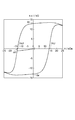
- FIG. 3 is a magnetization-magnetic field curve of Example 4 of the present invention.
- FIG. 4 is a magnetization-magnetic field curve of Comparative Example 3.
- FIG. 5 is a magnetization-magnetic field curve of Comparative Example 7.
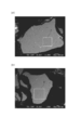
- FIG. 6A and 6B are backscattered electron images obtained by photographing a part of the cross section of the magnetic material according to Example 3 of the present invention with an SEM.
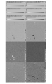
- FIG. 7 is a diagram showing a secondary electron image (SL), a reflected electron image (CP), and an element distribution of the region 7 in FIG. 6A based on an analysis by an electron beam microanalyzer (EPMA).
- FIG. 8 is a diagram showing a secondary electron image (SL), a reflected electron image (CP), and an element distribution of the region 8 in FIG. 6B based on the analysis by EPMA.
- 9a and 9b are backscattered electron images obtained by photographing a part of the cross section of the magnetic body of Comparative Example 5 with an SEM.
- FIG. 7 is a diagram showing a secondary electron image (SL), a reflected electron image (CP), and an element distribution of the region 7 in FIG. 6A based on an analysis by an electron beam microanalyzer (EPMA).
- FIG. 8 is a
- FIG. 10 is a diagram showing a secondary electron image (SL), a reflected electron image (CP), and an element distribution of the region 10 in FIG. 9A based on the analysis by EPMA.
- FIG. 11 is a diagram showing a secondary electron image (SL), a reflected electron image (CP), and an element distribution of the region 11 in FIG. 9B based on the analysis by EPMA.
- FIG. 12 (a) is a photograph of a cross section of the magnetic material of Example 3 of the present invention taken with a STEM, and FIG. 12 (b) is a diagram at each analysis location on the line segment LG2 in FIG. 12 (a). It is a table
- FIG. 13A is a photograph of a cross section of the magnetic material of Comparative Example 5 taken with a STEM
- FIG. 13B is a diagram of each element at each analysis location on the line LG5 in FIG. It is a table
- 14 (a) and 14 (b) are photographs obtained by photographing a cross section of the magnetic body of Example 3 of the present invention with a STEM
- FIG. 14 (c) is a photograph of FIGS. 14 (a) and 14 (b). It is a table
- 15 (a) and 15 (b) are photographs obtained by photographing a cross section of the magnetic material of Comparative Example 5 with a STEM
- FIG. 15 (c) is a view in FIGS. 15 (a) and 15 (b). It is a table
- the magnetic body according to the present embodiment preferably contains a rare earth element R, a transition metal element T, and boron B.
- the rare earth element R may be at least one selected from the group consisting of La, Ce, Pr, Nd, Pm, Sm, Eu, Gd, Tb, Dy, Ho, Er, Tm, Yb, and Lu.
- the rare earth element R is preferably at least one of Nd and Pr.
- the transition metal element T include Fe or Co.
- the transition metal element T is preferably Fe, but the magnetic material may contain both Fe and Co elements as T. When the magnetic material has the above composition, the saturation magnetic flux density and the residual magnetic flux density of the magnetic material are significantly improved.
- the magnetic substance further contains other elements such as Ca, Ni, Mn, Al, Cu, Nb, Zr, Ti, W, Mo, V, Ga, Zn, Si, and Bi as impurities or additives. But you can.
- the residual magnetic flux density Br of the magnetic body according to the present embodiment is 11 kG or more (1.1 T or more).
- the Br of the magnetic material is 12.5 kG or more (1.25 T or more).
- the upper limit value of Br of the magnetic material is not particularly limited, but is about 14 kG (1.4 T).
- the Br of the magnetic body according to the present embodiment is higher than the Br (10 kG) of the Sm 2 Co 17 sintered magnet that has been conventionally used as a variable magnetic force magnet. Therefore, in the variable magnetic flux motor using the magnetic body according to the present embodiment as the variable magnetic force magnet, the variable magnetic force magnet can have the same degree of magnetic force as the fixed magnet, and higher output and efficiency than before can be achieved. .
- the coercive force HcJ of the magnetic body according to the present embodiment is 5.0 kOe or less (400 A / m or less).
- the HcJ of the magnetic material is 4.0 kOe or less (320 A / m or less).
- the lower limit value of HcJ of the magnetic material is not particularly limited, but is about 1.0 kOe (80 A / m).
- the magnitude of the external magnetic field required for setting Br of the magnetic body according to the present embodiment to 0 is 1.10 HcJ or less. That is, the magnitude of the external magnetic field required for setting Br of the magnetic body according to the present embodiment to 0 is 110% or less of HcJ.
- the external magnetic field required to bring Br of the magnetic material to 0 is 1.05 HcJ or less.
- the lower limit value of the external magnetic field required to set Br of the magnetic material to 0 is about 1.00 HcJ.
- the external magnetic field (magnitude) required for setting Br of the magnetic material to 0 will be referred to as “mf” (magnetic field).
- HcJ is 5 kOe or less
- the magnitude mf of the external magnetic field required to set Br of the magnetic material to 0 is 1.10 HcJ or less. Therefore, the magnetic force change or magnetization reversal of the magnetic material is caused by a small external magnetic field. Can be reversibly repeated. Further, in the magnetic body of the present embodiment, the symmetry of the magnetization curve is maintained even when the magnetic force change or the magnetization reversal is repeated, and the stable magnetic flux density can be controlled.
- the magnetic body of the present embodiment is suitable as a variable magnetic magnet for a variable magnetic flux motor that is installed in home appliances such as washing machines or clothes dryers, hybrid cars, trains, elevators, and the like.
- the grain size of the crystals constituting the magnetic material is preferably 1 ⁇ m or less, and more preferably 0.5 ⁇ m.
- the magnetization mechanism of the magnetic material is likely to be a pinning type (or a single domain type), and the magnetic characteristics related to the external magnetic field mf are easily developed.
- the grain size of the crystals constituting the conventional Nd 2 Fe 14 B-based sintered magnet is about 5 ⁇ m, the magnetization mechanism is a new creation type.
- the magnetic body preferably contains Cu.
- a magnetic material having a fine crystal grain size generally has a high coercive force.
- a magnetic material having a high coercive force requires a large external magnetic field in order to change its magnetization state, and is not suitable for a variable magnetic force magnet for a variable magnetic flux motor.
- the coercive force can be easily reduced while maintaining the high residual magnetic flux density of the magnetic material and the pinning type magnetization mechanism. As a result, the above-described residual magnetic flux density, coercive force, and magnetic characteristics related to the external magnetic field can be remarkably exhibited.
- the Cu content in the magnetic material is preferably 1.0 to 1.25% by mass relative to the total mass of the magnetic material. As the Cu content increases, Br and HcJ tend to decrease. As the Cu content decreases, Br and HcJ tend to increase.
- the Cu content in the main phase particles constituting the magnetic material is preferably 0.5 to 0.6 atomic% with respect to all elements in the main phase particles.
- the main phase particles are crystal particles made of a main component of a magnetic material.
- the main components are, for example, rare earth element R, transition metal element T, and boron B (Nd 2 Fe 14 B).
- the magnetic material has a fine structure composed of main phase particles and the magnetization mechanism is a pinning type
- the content of Cu in the main phase particles is within the above range, so that the desired low
- the present inventors consider that a coercive force is easily obtained.
- the magnetic material may be a powder.
- the magnetic body may be a green compact obtained by pressing and solidifying a powder.
- the magnetic body may be a bonded magnet obtained by solidifying a magnetic powder or a green compact with a resin.
- the magnetic body may be a sintered body of magnetic particles.
- a raw material alloy is cast.
- an alloy containing the above-mentioned rare earth element R and transition metal elements T and B may be used.
- the raw material alloy may further contain the above-described elements as additives or impurities as necessary. What is necessary is just to adjust the chemical composition of a raw material alloy according to the chemical composition of the magnetic body to obtain finally.
- the raw material alloy may be an ingot or a powder.
- An alloy powder is formed from the raw material alloy by HDDR (Hydrogenation-Disposition-Desorption-Recombination) treatment.
- the HDDR process is a process of sequentially performing hydrogenation, disproportionation, dehydrogenation, and recombination of raw material alloys.
- the raw material alloy is maintained at 500 ° C. to 1000 ° C. in an H 2 gas atmosphere or a mixed atmosphere of H 2 gas and an inert gas, thereby hydrogenating the raw material alloy, and then H 2 in the atmosphere.
- the raw material alloy is dehydrogenated at 500 ° C. to 1000 ° C. until the partial pressure of the gas becomes 13 Pa or less, and then cooled.
- fine crystal particles Nd—TB magnetic powder having the composition of the Nd—TB rare earth magnet can be obtained.
- a raw material mixture is prepared by mixing an Nd—TB magnetic powder as a main raw material with Cu powder added under an inert gas atmosphere.
- the content of Cu powder in the raw material mixture is preferably 1.0 to 1.25% by mass with respect to the total mass of the raw material mixture. This makes it easier to obtain a magnetic material having the above magnetic characteristics.
- Br and HcJ of the obtained magnetic body tend to decrease. There exists a tendency for Br and HcJ of the magnetic body to increase, so that the content rate of Cu powder decreases.
- the powdered magnetic material is completed by heat-treating the raw material mixture in an inert atmosphere of 700 to 950 ° C.
- Cu is thermally diffused, and the Nd—TB magnetic powder has a low coercive force while maintaining the pinning-type magnetization mechanism.
- the Nd—TB magnetic powder to which Cu is added does not substantially grow during heat treatment at 700 to 950 ° C., and maintains the microstructure before the heat treatment.
- the raw material mixture is pressure-molded in a magnetic field to form a molded body.
- the strength of the magnetic field applied to the raw material mixture during molding is preferably 800 kA / m or more.
- the pressure applied to the raw material mixture during molding is preferably about 10 to 500 MPa.
- a uniaxial pressing method or an isotropic pressing method such as CIP may be used as the molding method.
- the obtained molded body is fired to form a sintered body.
- the firing temperature may be about 700 to 1200 ° C.
- the firing time may be about 0.1 to 100 hours. You may perform a baking process in multiple times.
- the firing step is preferably performed in a vacuum or in an inert gas atmosphere such as Ar gas.
- An aging treatment may be applied to the sintered body after firing. You may perform the process which cuts out the magnetic body of a desired dimension from a sintered compact.
- a protective layer may be formed on the surface of the sintered body.
- the protective layer can be applied without particular limitation as long as it is usually formed as a layer protecting the surface of the rare earth magnet. Examples of the protective layer include a resin layer formed by painting or vapor deposition polymerization method, a metal layer formed by plating or vapor phase method, an inorganic layer formed by coating method or vapor phase method, an oxide layer, a chemical conversion treatment layer, etc. It is done.
- a bonded magnet may be manufactured by mixing the powdered magnetic material obtained by the above method and a resin such as plastic or rubber and then curing the resin.
- a bonded magnet may be manufactured by impregnating a resin into a green compact obtained by pressing and hardening a magnetic powder, and then curing the resin.
- Example 4 An ingot of Nd—Fe—B alloy containing the elements shown in Table 1 was produced by centrifugal casting. The content of each element in the ingot was adjusted to the value shown in Table 1. As is clear from Table 1, the composition of the ingot is almost equal to Nd 2 Fe 14 B. The presence or absence of impurity elements inevitably contained in the ingot was analyzed. Table 2 shows the type of each impurity element and the content of each impurity element in the ingot. The composition of the ingot was analyzed by fluorescent X-ray analysis (XRF).
- XRF fluorescent X-ray analysis
- Alloy powder was formed from the ingot by HDDR treatment.
- the HDDR process after the ingot is hydrogenated by maintaining the ingot at 800 ° C. in an H 2 gas atmosphere, the ingot is kept at 850 ° C. until the partial pressure of H 2 gas in the atmosphere becomes 1 Pa or less. Was dehydrogenated and then cooled.
- the ingot obtained through these steps was pulverized in an Ar gas atmosphere and screened to obtain an Nd—Fe—B based magnetic powder having a particle size of 212 ⁇ m or less.
- a raw material mixture was prepared by mixing Cu powder with Nd—Fe—B magnetic powder in an Ar gas atmosphere.
- the content of Cu powder in the raw material mixture (hereinafter referred to as “Cu addition amount”) was adjusted to 1.25% by mass with respect to the total mass of the raw material mixture.
- the purity of the Cu powder was 99.9% by mass, and the particle size of the Cu powder was 10 ⁇ m or less.
- a coffee mill was used for mixing. The mixing time was 1 minute. Mixing was performed in an Ar gas atmosphere.
- the raw material mixture was heat-treated at 700 ° C. in an Ar gas atmosphere to obtain a magnetic body of Example 4.
- the raw material mixture was heated at 700 ° C. for 4 hours.
- FIG. 1a shows a photograph of the fracture surface of the magnetic material of Example 4 taken with a scanning electron microscope (SEM).
- SEM scanning electron microscope
- photographed the cross section of the magnetic body of Example 4 with the scanning transmission electron microscope (STEM) is shown in FIG.
- FIGS. 1a and 1b it was confirmed that the magnetic material of Example 4 was an aggregate of fine magnetic particles having a particle size of 1 ⁇ m or less.
- Example 4 [Evaluation of magnetic properties]
- the magnetic body of Example 4 was pulverized using a mortar in an Ar gas atmosphere and sieved to obtain a magnetic powder having a particle size of 212 ⁇ m or less.
- This powder and paraffin are packed in a case, and in a state where the paraffin is melted, a magnetic field of 1 Tesla is applied to orient the magnetic powder, and a magnetization-magnetic field curve is obtained using a vibrating sample magnetometer (VSM).
- VSM vibrating sample magnetometer
- the magnitude of the magnetic field applied to the magnetic powder was controlled in the range of -25 to 25 kOe.
- Table 5 shows the measurement results of the residual magnetic flux density (Br) and the coercive force (HcJ) of the magnetic body of Example 4.
- the magnetization-magnetic field curve of Example 4 is shown in FIG.
- a reverse magnetic field is applied to a magnetic material that has been magnetized until saturation in the positive direction after measuring the magnetization-magnetic field curve, and the residual magnetic flux density Br becomes zero when the magnetic field is removed.
- the magnitude of the magnetic field was determined.
- Table 5 shows the absolute value (mf) of the reverse magnetic field in which Br becomes 0 and the ratio (mf / HcJ) to the coercive force HcJ.
- Example 1 to 3, 5 to 6, Comparative Examples 1 to 8 In each Example and Comparative Example, the amount of Cu added was adjusted to the value shown in Table 5. In each Example and Comparative Example, the heat treatment temperature of the raw material mixture was adjusted to the values shown in Table 5. Except for these matters, powdery magnetic materials of Examples and Comparative Examples were produced in the same manner as in Example 4. The photograph which image
- the ratio of mf to Br, HcJ, mf, and HcJ in each example and comparative example was determined in the same manner as in Example 4. The results are shown in Table 5.
- the magnetization-magnetic field curve of Comparative Example 3 is shown in FIG.
- the magnetization-magnetic field curve of Comparative Example 7 is shown in FIG.
- FIG. 6a and 6b are backscattered electron images of the magnetic material cross section of Example 3.
- FIG. Region 7 in FIG. 6a and region 8 in FIG. 6b are positions (measurement regions) where data for elemental mapping is collected by EPMA analysis.
- the size of the region 7 is 20 ⁇ 20 ⁇ m.
- the size of the region 8 is 51.2 ⁇ 51.2 ⁇ m.
- FIG. 7 is an element distribution map in the region 7 based on the EPMA analysis.
- FIG. 8 is an element distribution map in the region 8 based on the EPMA analysis.
- FIG. 9a and 9b are backscattered electron images of a part of the cross section of the magnetic material of Comparative Example 5.
- FIG. Region 10 in FIG. 9a and region 11 in FIG. 9b are positions (measurement regions) where data for elemental mapping is collected by EPMA analysis.
- the size of the region 10 is 20 ⁇ 20 ⁇ m.
- the area 11 has a size of 51.2 ⁇ 51.2 ⁇ m.
- FIG. 10 is an element distribution map in the region 10 based on the EPMA analysis.
- FIG. 11 is an element distribution map in the region 11 based on the EPMA analysis.
- the Cu added in Example 3 appeared to be segregated without being uniformly dispersed in the magnetic substance.
- Example 3 [STEM-EDS analysis / line analysis] The cross sections of the magnetic materials obtained in Example 3 and Comparative Example 5 were analyzed using energy dispersive X-ray spectroscopy (STEM-EDS) included in the scanning transmission electron microscope.
- STEM-EDS energy dispersive X-ray spectroscopy
- the results of Example 3 are shown in FIGS. 12 (a) and 12 (b).
- the analysis results of Comparative Example 5 are shown in FIGS. 13 (a) and 13 (b).
- LG20000 to LG20029 in FIG. 12 (b) are locations (analysis locations) where the content of each element was measured by STEM-EDS, and were arranged on the line segment LG2 in FIG. 12 (a) at approximately equal intervals. Corresponds to each point. LG50000 to LG50029 in FIG.
- FIGS. 12B and 13B are locations (analysis locations) where the content of each element was measured by STEM-EDS, and were arranged on the line segment LG5 in FIG. 13A at approximately equal intervals. Corresponds to each point.
- the unit of element content in each analysis location shown in FIGS. 12B and 13B is “atomic%”.
- Each arrow in Drawing 12 (a) and Drawing 13 (a) shows the direction which performed line analysis.
- LG20000 in FIG. 12B is a starting point of line analysis, and is located on the start point side of the arrow in FIG.
- LG20029 in FIG. 12B is the end point of the line analysis, and is located on the tip side of the arrow in FIG.
- LG50000 in FIG. 13B is the starting point of the line analysis and is located on the start point side of the arrow in FIG.
- LG50029 in FIG. 13B is the end point of the line analysis, and is located on the tip side of the arrow in FIG.
- the length (unit: ⁇ m) given to LG20000 to LG20029 in FIG. 12 (b) is the distance from LG20000 at each analysis location.
- the length (unit: ⁇ m) given to LG50000 to LG50029 in FIG. 13B is the distance from the LG50000 at each analysis location.
- Example 3 [STEM-EDS analysis / point analysis] The cross sections of the magnetic materials obtained in Example 3 and Comparative Example 5 were analyzed using STEM-EDS.
- the analysis results of Example 3 are shown in FIGS. 14 (a), 14 (b), and 14 (c).
- the analysis results of Comparative Example 5 are shown in FIGS. 15 (a), 15 (b) and 15 (c).
- the content of each element at each measurement location “+” shown in FIGS. 14A and 14B was measured by STEM-EDS.
- FIG.14 (c) shows the content rate of each element in each measurement location in Fig.14 (a) and 14 (b).
- the content of each element at each measurement location “+” shown in FIGS. 15A and 15B was measured by STEM-EDS.
- FIG.15 (c) shows the content rate of each element in each measurement location in Fig.15 (a) and 15 (b).
- the “grain boundary” described in FIGS. 14C and 15C means a boundary region between two crystal grains (main phase grains) constituting the magnetic body.
- “Grain boundary triple point” means a phase surrounded by three or more crystal grains constituting a magnetic material.
- Table 5 shows the Cu content in the main phase particles of each Example and Comparative Example obtained from the results of point analysis.
- Table 6 shows the relationship between the residual magnetic flux density described in Table 5, the Cu addition amount, and the heat treatment temperature.
- Table 7 shows the relationship between the coercive force described in Table 5, the amount of Cu added, and the heat treatment temperature.
- Table 8 shows the relationship among mf / HcJ, Cu addition amount and heat treatment temperature described in Table 5.
- Table 9 shows the relationship between the Cu content in the main phase particles described in Table 5, the amount of Cu added, and the heat treatment temperature. In Tables 6 to 9, numerical values marked with “*” are those of the examples.
- Comparative Examples 1, 3 and 5 in which the amount of Cu added was 0 and the heat treatment temperature was 700 to 900 ° C., no change in magnetism was observed with the change in the heat treatment temperature. That is, no significant difference was confirmed between the magnetic materials of Comparative Examples 1, 3 and 5 and the raw material mixture.
- Comparative Example 7 in which the amount of Cu added was 0 and the heat treatment temperature was 950 ° C., grain growth and an increase in mf / HcJ were observed.
- the grain growth in Comparative Example 7 is considered to be caused by the heat treatment temperature being too high.
- the increase in mf / HcJ in Comparative Example 7 is considered to be due to the fact that the magnetization mechanism of the magnetic material has become a nucleation type.
- the present invention Since the present invention has a high residual magnetic flux density and can reversibly change the magnetic force by a small external magnetic field, it is suitable for a variable magnetic flux motor installed in home appliances, hybrid cars, trains, elevators, and the like. It is suitable as a variable magnetic magnet.
Abstract
Description
本実施形態に係る磁性体は、希土類元素R、遷移金属元素T及びホウ素Bを含むことが好ましい。希土類元素Rは、La,Ce,Pr,Nd,Pm,Sm,Eu,Gd,Tb,Dy,Ho,Er,Tm,Yb及びLuからなる群より選ばれる少なくとも一種であればよい。特に、希土類元素RがNd及びPrのうち少なくともいずれか一種であることが好ましい。遷移金属元素Tとしては、Fe又はCoが挙げられる。遷移金属元素Tとしては、Feが好ましいが、磁性体がTとしてFeとCoの両元素を含有してもよい。磁性体が上記の組成を有することにより、磁性体の飽和磁束密度及び残留磁束密度が顕著に向上する。なお、磁性体は、不純物又は添加物として、Ca、Ni、Mn、Al、Cu、Nb、Zr、Ti、W、Mo、V、Ga、Zn、Si、及びBi等の他の元素を更に含んでもよい。 (Magnetic material)
The magnetic body according to the present embodiment preferably contains a rare earth element R, a transition metal element T, and boron B. The rare earth element R may be at least one selected from the group consisting of La, Ce, Pr, Nd, Pm, Sm, Eu, Gd, Tb, Dy, Ho, Er, Tm, Yb, and Lu. In particular, the rare earth element R is preferably at least one of Nd and Pr. Examples of the transition metal element T include Fe or Co. The transition metal element T is preferably Fe, but the magnetic material may contain both Fe and Co elements as T. When the magnetic material has the above composition, the saturation magnetic flux density and the residual magnetic flux density of the magnetic material are significantly improved. The magnetic substance further contains other elements such as Ca, Ni, Mn, Al, Cu, Nb, Zr, Ti, W, Mo, V, Ga, Zn, Si, and Bi as impurities or additives. But you can.
磁性体の製造では、まず原料合金を鋳造する。原料合金としては、上述した希土類元素R,遷移金属元素T及びBを含むものを用いればよい。原料合金は、必要に応じて、添加物又は不純物として上述した元素を更に含んでもよい。原料合金の化学組成は、最終的に得たい磁性体の化学組成に応じて調整すればよい。原料合金は鋳塊であっても粉末であってもよい。 (Method for producing magnetic material)
In the manufacture of a magnetic body, first, a raw material alloy is cast. As the raw material alloy, an alloy containing the above-mentioned rare earth element R and transition metal elements T and B may be used. The raw material alloy may further contain the above-described elements as additives or impurities as necessary. What is necessary is just to adjust the chemical composition of a raw material alloy according to the chemical composition of the magnetic body to obtain finally. The raw material alloy may be an ingot or a powder.
遠心鋳造法により、表1に示す元素を含有するNd-Fe-B系合金の鋳塊を作製した。鋳塊中の各元素の含有率は表1に示す値に調整した。なお、表1から明らかなように、鋳塊の組成はNd2Fe14Bにほぼ等しい。鋳塊に不可避的に含まれる不純物元素の有無を分析した。各不純物元素の種類及び鋳塊における各不純物元素の含有率を表2に示す。なお、鋳塊の組成は蛍光X線分析(XRF)で分析した。 Example 4
An ingot of Nd—Fe—B alloy containing the elements shown in Table 1 was produced by centrifugal casting. The content of each element in the ingot was adjusted to the value shown in Table 1. As is clear from Table 1, the composition of the ingot is almost equal to Nd 2 Fe 14 B. The presence or absence of impurity elements inevitably contained in the ingot was analyzed. Table 2 shows the type of each impurity element and the content of each impurity element in the ingot. The composition of the ingot was analyzed by fluorescent X-ray analysis (XRF).

実施例4の磁性体を、Arガス雰囲気中で乳鉢を用いて粉砕し、篩い分けを行って、粒径が212μm以下である磁性体の粉末を得た。この粉末とパラフィンとをケースに詰めて、パラフィンを融解させた状態で1テスラの磁界を印加して磁性体の粉末を配向させ、振動試料型磁力計(VSM)を用いて、磁化-磁界曲線を測定して磁気特性を求めた。磁性体の粉末に印加した磁界の大きさは-25~25kOeの範囲内に制御した。実施例4の磁性体の残留磁束密度(Br)及び保磁力(HcJ)の測定結果を表5に示す。実施例4の磁化-磁界曲線を図3に示す。 [Evaluation of magnetic properties]
The magnetic body of Example 4 was pulverized using a mortar in an Ar gas atmosphere and sieved to obtain a magnetic powder having a particle size of 212 μm or less. This powder and paraffin are packed in a case, and in a state where the paraffin is melted, a magnetic field of 1 Tesla is applied to orient the magnetic powder, and a magnetization-magnetic field curve is obtained using a vibrating sample magnetometer (VSM). Was measured to determine the magnetic properties. The magnitude of the magnetic field applied to the magnetic powder was controlled in the range of -25 to 25 kOe. Table 5 shows the measurement results of the residual magnetic flux density (Br) and the coercive force (HcJ) of the magnetic body of Example 4. The magnetization-magnetic field curve of Example 4 is shown in FIG.
各実施例及び比較例では、Cu添加量を表5に示す値に調整した。各実施例及び比較例では、原料混合物の熱処理温度を表5に示す値に調整した。これらの事項以外は、実施例4と同様の方法で、各実施例及び比較例の粉末状の磁性体を作製した。比較例7の磁性体の破断面をSEMで撮影した写真を図2に示す。比較例7では、実施例4とは対照的に、磁性粒子が粒成長しており、実施例4のような微細な組織構造は見られなかった。 (Examples 1 to 3, 5 to 6, Comparative Examples 1 to 8)
In each Example and Comparative Example, the amount of Cu added was adjusted to the value shown in Table 5. In each Example and Comparative Example, the heat treatment temperature of the raw material mixture was adjusted to the values shown in Table 5. Except for these matters, powdery magnetic materials of Examples and Comparative Examples were produced in the same manner as in Example 4. The photograph which image | photographed the fracture surface of the magnetic body of the comparative example 7 with SEM is shown in FIG. In Comparative Example 7, in contrast to Example 4, the magnetic particles were grown, and the fine structure as in Example 4 was not observed.
実施例3で得られた磁性体の断面を走査電子顕微鏡が備える電子線マイクロアナライザー(SEM-EPMA)を用いて分析した。実施例3の分析結果を図6~8示す。比較例5で得られた磁性体の断面をSEM-EPMAを用いて分析した。比較例5の分析結果を図9~11に示す。 [SEM-EPMA analysis]
The cross section of the magnetic material obtained in Example 3 was analyzed using an electron beam microanalyzer (SEM-EPMA) provided in the scanning electron microscope. The analysis results of Example 3 are shown in FIGS. The cross section of the magnetic material obtained in Comparative Example 5 was analyzed using SEM-EPMA. The analysis results of Comparative Example 5 are shown in FIGS.
実施例3及び比較例5で得られた磁性体の断面を、走査透過電子顕微鏡が備えるエネルギー分散型X線分光(STEM-EDS)を用いて分析した。実施例3の結果を図12(a)及び12(b)に示す。比較例5の分析結果を図13(a)及び13(b)に示す。図12(b)中のLG20000~LG20029は、STEM-EDSによって各元素の含有率を測定した箇所(分析箇所)であり、図12(a)中の線分LG2上に略等間隔で配列した各点に対応する。図13(b)中のLG50000~LG50029は、STEM-EDSによって各元素の含有量を測定した箇所(分析箇所)であり、図13(a)中の線分LG5上に略等間隔で配列した各点に対応する。図12(b)及び図13(b)に示す各分析箇所における元素の含有率の単位は「原子%」である。図12(a)及び図13(a)中の各矢印は線分析を行った方向を示す。図12(b)のLG20000は、線分析の開始点であり、図12(a)の矢印の始点側に位置する。図12(b)のLG20029は線分析の終点であり、図12(a)の矢印の先端側に位置する。図13(b)のLG50000は、線分析の開始点であり、図13(a)の矢印の始点側に位置する。図13(b)のLG50029は線分析の終点であり、図13(a)の矢印の先端側に位置する。図12(b)中のLG20000~LG20029に付された長さ(単位:μm)は、各分析箇所のLG20000からの距離である。図13(b)中のLG50000~LG50029に付された長さ(単位:μm)は、各分析箇所のLG50000からの距離である。 [STEM-EDS analysis / line analysis]
The cross sections of the magnetic materials obtained in Example 3 and Comparative Example 5 were analyzed using energy dispersive X-ray spectroscopy (STEM-EDS) included in the scanning transmission electron microscope. The results of Example 3 are shown in FIGS. 12 (a) and 12 (b). The analysis results of Comparative Example 5 are shown in FIGS. 13 (a) and 13 (b). LG20000 to LG20029 in FIG. 12 (b) are locations (analysis locations) where the content of each element was measured by STEM-EDS, and were arranged on the line segment LG2 in FIG. 12 (a) at approximately equal intervals. Corresponds to each point. LG50000 to LG50029 in FIG. 13B are locations (analysis locations) where the content of each element was measured by STEM-EDS, and were arranged on the line segment LG5 in FIG. 13A at approximately equal intervals. Corresponds to each point. The unit of element content in each analysis location shown in FIGS. 12B and 13B is “atomic%”. Each arrow in Drawing 12 (a) and Drawing 13 (a) shows the direction which performed line analysis. LG20000 in FIG. 12B is a starting point of line analysis, and is located on the start point side of the arrow in FIG. LG20029 in FIG. 12B is the end point of the line analysis, and is located on the tip side of the arrow in FIG. LG50000 in FIG. 13B is the starting point of the line analysis and is located on the start point side of the arrow in FIG. LG50029 in FIG. 13B is the end point of the line analysis, and is located on the tip side of the arrow in FIG. The length (unit: μm) given to LG20000 to LG20029 in FIG. 12 (b) is the distance from LG20000 at each analysis location. The length (unit: μm) given to LG50000 to LG50029 in FIG. 13B is the distance from the LG50000 at each analysis location.
実施例3及び比較例5で得られた各磁性体の断面をSTEM-EDSを用いて分析した。実施例3の分析結果を図14(a)、14(b)及び14(c)に示す。比較例5の分析結果を図15(a)、15(b)及び15(c)に示す。図14(a)及び14(b)に示す各測定箇所「+」における各元素の含有率をSTEM-EDSによって測定した。図14(c)は、図14(a)及び14(b)中の各測定箇所における各元素の含有率を示す。図15(a)及び15(b)に示す各測定箇所「+」における各元素の含有率をSTEM-EDSによって測定した。図15(c)は、図15(a)及び15(b)中の各測定箇所における各元素の含有率を示す。なお、図14(c)及び図15(c)に記載の「粒界」とは、磁性体を構成する2つの結晶粒子(主相粒子)の境界領域を意味する。「粒界三重点」とは、磁性体を構成する3つ以上の結晶粒子に囲まれた相を意味する。 [STEM-EDS analysis / point analysis]
The cross sections of the magnetic materials obtained in Example 3 and Comparative Example 5 were analyzed using STEM-EDS. The analysis results of Example 3 are shown in FIGS. 14 (a), 14 (b), and 14 (c). The analysis results of Comparative Example 5 are shown in FIGS. 15 (a), 15 (b) and 15 (c). The content of each element at each measurement location “+” shown in FIGS. 14A and 14B was measured by STEM-EDS. FIG.14 (c) shows the content rate of each element in each measurement location in Fig.14 (a) and 14 (b). The content of each element at each measurement location “+” shown in FIGS. 15A and 15B was measured by STEM-EDS. FIG.15 (c) shows the content rate of each element in each measurement location in Fig.15 (a) and 15 (b). In addition, the “grain boundary” described in FIGS. 14C and 15C means a boundary region between two crystal grains (main phase grains) constituting the magnetic body. “Grain boundary triple point” means a phase surrounded by three or more crystal grains constituting a magnetic material.


Claims (3)
- 残留磁束密度Brが11kG以上であり、
保磁力HcJが5kOe以下であり、
前記残留磁束密度Brを0にするために要する外部磁界が1.10HcJ以下である、
磁性体。 The residual magnetic flux density Br is 11 kG or more,
The coercive force HcJ is 5 kOe or less,
The external magnetic field required for setting the residual magnetic flux density Br to 0 is 1.10 HcJ or less.
Magnetic material. - 希土類元素R、遷移金属元素T及びホウ素Bを含む、
請求項1に記載の磁性体。 Including rare earth element R, transition metal element T and boron B,
The magnetic body according to claim 1. - 結晶粒子径が1μm以下である、
請求項1又は2に記載の磁性体。
The crystal particle diameter is 1 μm or less,
The magnetic body according to claim 1 or 2.
Priority Applications (4)
| Application Number | Priority Date | Filing Date | Title |
|---|---|---|---|
| CN201180063123.4A CN103282976B (en) | 2010-12-27 | 2011-12-19 | Magnetic body |
| EP11853050.0A EP2660829A4 (en) | 2010-12-27 | 2011-12-19 | Magnetic body |
| JP2012550846A JP5527434B2 (en) | 2010-12-27 | 2011-12-19 | Magnetic material |
| US13/997,788 US8981888B2 (en) | 2010-12-27 | 2011-12-19 | Magnetic body |
Applications Claiming Priority (2)
| Application Number | Priority Date | Filing Date | Title |
|---|---|---|---|
| JP2010-290821 | 2010-12-27 | ||
| JP2010290821 | 2010-12-27 |
Publications (1)
| Publication Number | Publication Date |
|---|---|
| WO2012090765A1 true WO2012090765A1 (en) | 2012-07-05 |
Family
ID=46382876
Family Applications (1)
| Application Number | Title | Priority Date | Filing Date |
|---|---|---|---|
| PCT/JP2011/079401 WO2012090765A1 (en) | 2010-12-27 | 2011-12-19 | Magnetic body |
Country Status (5)
| Country | Link |
|---|---|
| US (1) | US8981888B2 (en) |
| EP (1) | EP2660829A4 (en) |
| JP (1) | JP5527434B2 (en) |
| CN (1) | CN103282976B (en) |
| WO (1) | WO2012090765A1 (en) |
Cited By (10)
| Publication number | Priority date | Publication date | Assignee | Title |
|---|---|---|---|---|
| EP2722856A1 (en) * | 2012-10-17 | 2014-04-23 | Shin-Etsu Chemical Co., Ltd. | Rare earth sintered magnet and making method |
| JP5686213B1 (en) * | 2014-03-28 | 2015-03-18 | Tdk株式会社 | R-T-B permanent magnet |
| JP5686212B1 (en) * | 2014-03-28 | 2015-03-18 | Tdk株式会社 | R-T-B permanent magnet |
| JP5729511B1 (en) * | 2014-04-21 | 2015-06-03 | Tdk株式会社 | R-T-B permanent magnet and rotating machine |
| JP2015213146A (en) * | 2014-04-15 | 2015-11-26 | Tdk株式会社 | Permanent magnet and variable magnetic flux motor |
| JP2017139259A (en) * | 2016-02-01 | 2017-08-10 | Tdk株式会社 | Alloy for r-t-b-based sintered magnet and r-t-b-based sintered magnet |
| JP2018133578A (en) * | 2013-11-27 | 2018-08-23 | シアメン タングステン カンパニー リミテッド | Low-b rare earth magnet |
| US10784029B2 (en) | 2017-03-31 | 2020-09-22 | Tdk Corporation | R-T-B based permanent magnet |
| US11120931B2 (en) | 2017-03-31 | 2021-09-14 | Tdk Corporation | R-T-B based permanent magnet |
| US11837915B2 (en) | 2018-05-29 | 2023-12-05 | Tdk Corporation | R-T-B-based magnet, motor, and generator |
Families Citing this family (5)
| Publication number | Priority date | Publication date | Assignee | Title |
|---|---|---|---|---|
| WO2014068655A1 (en) * | 2012-10-30 | 2014-05-08 | 三菱電機株式会社 | Electric motor with embedded permanent magnet, and refrigeration and air conditioning equipment equipped with same |
| JP5686214B1 (en) * | 2014-03-28 | 2015-03-18 | Tdk株式会社 | R-T-B permanent magnet |
| JP6635054B2 (en) * | 2017-01-06 | 2020-01-22 | 株式会社村田製作所 | Resistance element and method of manufacturing the same |
| CN110556223B (en) * | 2019-09-30 | 2021-07-02 | 厦门钨业股份有限公司 | Neodymium-iron-boron magnet material and preparation method and application thereof |
| CN114284018A (en) * | 2021-12-27 | 2022-04-05 | 烟台正海磁性材料股份有限公司 | Neodymium-iron-boron magnet and preparation method and application thereof |
Citations (5)
| Publication number | Priority date | Publication date | Assignee | Title |
|---|---|---|---|---|
| JPH1064710A (en) * | 1996-08-19 | 1998-03-06 | Sumitomo Special Metals Co Ltd | Isotropic permanent magnet having high magnetic flux density and manufacture thereof |
| JPH1088295A (en) * | 1996-09-19 | 1998-04-07 | Santoku Kinzoku Kogyo Kk | Alloy for rare earth-iron-boron type bond magnet |
| JP2007077506A (en) * | 2006-10-25 | 2007-03-29 | Santoku Corp | Rare earth-iron-boron based composite magnet alloy used for bond magnet, and method for producing the same |
| JP2010034522A (en) | 2008-06-23 | 2010-02-12 | Toshiba Corp | Permanent magnet, method of manufacturing the same, permanent magnet for motor, and permanent magnet motor |
| JP2010114371A (en) * | 2008-11-10 | 2010-05-20 | Shin-Etsu Chemical Co Ltd | Sm-R-T-B(-M)-BASED SINTERED MAGNET |
Family Cites Families (13)
| Publication number | Priority date | Publication date | Assignee | Title |
|---|---|---|---|---|
| JP2720040B2 (en) * | 1988-02-26 | 1998-02-25 | 住友特殊金属株式会社 | Sintered permanent magnet material and its manufacturing method |
| CA2023924A1 (en) * | 1989-12-19 | 1991-06-20 | Earl G. Brewer | Alloying low-level additives into hot-worked nd-fe-b magnets |
| JPH0475302A (en) * | 1990-07-18 | 1992-03-10 | Tokin Corp | R-fe-b bond magnet production method |
| ES2120227T3 (en) * | 1994-09-19 | 1998-10-16 | Siemens Ag | DIFFERENTIAL CURRENT PROTECTION SWITCH WITH SPECIAL CORE MATERIAL. |
| CN1136588C (en) * | 1995-10-16 | 2004-01-28 | 坩埚材料有限公司 | Improved Re-Fe-B magnets and mfg. method for the same |
| US7199690B2 (en) * | 2003-03-27 | 2007-04-03 | Tdk Corporation | R-T-B system rare earth permanent magnet |
| JP4415374B2 (en) * | 2004-03-31 | 2010-02-17 | Tdk株式会社 | Manufacturing method of rare earth sintered magnet |
| JP4730546B2 (en) * | 2006-04-14 | 2011-07-20 | 信越化学工業株式会社 | Rare earth permanent magnet manufacturing method |
| CN100454449C (en) * | 2006-04-24 | 2009-01-21 | 严高林 | Method for regenerating high-performance permanent magnet by degenerated rare earth permanent magnet material |
| CN101379574B (en) * | 2006-11-30 | 2012-05-23 | 日立金属株式会社 | R-Fe-B microcrystalline high-density magnet and process for production thereof |
| JP5262643B2 (en) * | 2008-12-04 | 2013-08-14 | 信越化学工業株式会社 | Nd-based sintered magnet and manufacturing method thereof |
| KR20140114057A (en) * | 2009-07-08 | 2014-09-25 | 티디케이가부시기가이샤 | Ferrite magnetic material |
| MY165562A (en) * | 2011-05-02 | 2018-04-05 | Shinetsu Chemical Co | Rare earth permanent magnets and their preparation |
-
2011
- 2011-12-19 EP EP11853050.0A patent/EP2660829A4/en not_active Withdrawn
- 2011-12-19 US US13/997,788 patent/US8981888B2/en active Active
- 2011-12-19 JP JP2012550846A patent/JP5527434B2/en active Active
- 2011-12-19 CN CN201180063123.4A patent/CN103282976B/en active Active
- 2011-12-19 WO PCT/JP2011/079401 patent/WO2012090765A1/en active Application Filing
Patent Citations (5)
| Publication number | Priority date | Publication date | Assignee | Title |
|---|---|---|---|---|
| JPH1064710A (en) * | 1996-08-19 | 1998-03-06 | Sumitomo Special Metals Co Ltd | Isotropic permanent magnet having high magnetic flux density and manufacture thereof |
| JPH1088295A (en) * | 1996-09-19 | 1998-04-07 | Santoku Kinzoku Kogyo Kk | Alloy for rare earth-iron-boron type bond magnet |
| JP2007077506A (en) * | 2006-10-25 | 2007-03-29 | Santoku Corp | Rare earth-iron-boron based composite magnet alloy used for bond magnet, and method for producing the same |
| JP2010034522A (en) | 2008-06-23 | 2010-02-12 | Toshiba Corp | Permanent magnet, method of manufacturing the same, permanent magnet for motor, and permanent magnet motor |
| JP2010114371A (en) * | 2008-11-10 | 2010-05-20 | Shin-Etsu Chemical Co Ltd | Sm-R-T-B(-M)-BASED SINTERED MAGNET |
Cited By (15)
| Publication number | Priority date | Publication date | Assignee | Title |
|---|---|---|---|---|
| EP3410446A1 (en) * | 2012-10-17 | 2018-12-05 | Shin-Etsu Chemical Co., Ltd. | Rare earth sintered magnet and making method |
| EP2722856A1 (en) * | 2012-10-17 | 2014-04-23 | Shin-Etsu Chemical Co., Ltd. | Rare earth sintered magnet and making method |
| US9734947B2 (en) | 2012-10-17 | 2017-08-15 | Shin-Etsu Chemical Co., Ltd. | Rare earth sintered magnet and making method |
| JP2018133578A (en) * | 2013-11-27 | 2018-08-23 | シアメン タングステン カンパニー リミテッド | Low-b rare earth magnet |
| JP5686213B1 (en) * | 2014-03-28 | 2015-03-18 | Tdk株式会社 | R-T-B permanent magnet |
| JP5686212B1 (en) * | 2014-03-28 | 2015-03-18 | Tdk株式会社 | R-T-B permanent magnet |
| US9850559B2 (en) | 2014-04-15 | 2017-12-26 | Tdk Corporation | Permanent magnet and variable magnetic flux motor |
| JP2015213146A (en) * | 2014-04-15 | 2015-11-26 | Tdk株式会社 | Permanent magnet and variable magnetic flux motor |
| US10020102B2 (en) | 2014-04-21 | 2018-07-10 | Tdk Corporation | R-T-B based permanent magnet and rotating machine |
| JP2015207662A (en) * | 2014-04-21 | 2015-11-19 | Tdk株式会社 | R-t-b-based permanent magnet and rotary machine |
| JP5729511B1 (en) * | 2014-04-21 | 2015-06-03 | Tdk株式会社 | R-T-B permanent magnet and rotating machine |
| JP2017139259A (en) * | 2016-02-01 | 2017-08-10 | Tdk株式会社 | Alloy for r-t-b-based sintered magnet and r-t-b-based sintered magnet |
| US10784029B2 (en) | 2017-03-31 | 2020-09-22 | Tdk Corporation | R-T-B based permanent magnet |
| US11120931B2 (en) | 2017-03-31 | 2021-09-14 | Tdk Corporation | R-T-B based permanent magnet |
| US11837915B2 (en) | 2018-05-29 | 2023-12-05 | Tdk Corporation | R-T-B-based magnet, motor, and generator |
Also Published As
| Publication number | Publication date |
|---|---|
| JP5527434B2 (en) | 2014-06-18 |
| EP2660829A4 (en) | 2017-11-29 |
| EP2660829A1 (en) | 2013-11-06 |
| US20130271249A1 (en) | 2013-10-17 |
| CN103282976B (en) | 2017-02-08 |
| JPWO2012090765A1 (en) | 2014-06-05 |
| CN103282976A (en) | 2013-09-04 |
| US8981888B2 (en) | 2015-03-17 |
Similar Documents
| Publication | Publication Date | Title |
|---|---|---|
| JP5527434B2 (en) | Magnetic material | |
| JP6330813B2 (en) | R-T-B system sintered magnet and motor | |
| EP3046119B1 (en) | Permanent magnet, motor, and power generator | |
| EP1377691B1 (en) | Method of making a rare earth alloy sintered compact | |
| JP6848735B2 (en) | RTB series rare earth permanent magnet | |
| WO2015020183A1 (en) | R-t-b type sintered magnet, and motor | |
| EP2979279B1 (en) | Permanent magnet, and motor and generator using the same | |
| KR101585483B1 (en) | Sintered Magnet Based on MnBi Having Improved Heat Stability and Method of Preparing the Same | |
| US10304600B2 (en) | Permanent magnet, and motor and generator using the same | |
| US10256016B2 (en) | Rare earth based magnet | |
| JP6142794B2 (en) | Rare earth magnets | |
| US9773592B2 (en) | Permanent magnet, and motor and generator using the same | |
| JP2010123722A (en) | Permanent magnet, permanent magnet motor using the same, and power generator | |
| JP2011049441A (en) | Method for manufacturing r-t-b based permanent magnet | |
| JP5288276B2 (en) | Manufacturing method of RTB-based permanent magnet | |
| JP2008060241A (en) | High resistance rare-earth permanent magnet | |
| JP6142793B2 (en) | Rare earth magnets | |
| JP2853838B2 (en) | Manufacturing method of rare earth permanent magnet | |
| JP7151270B2 (en) | R-T-B rare earth permanent magnet | |
| CN110620004A (en) | Permanent magnet and method for manufacturing permanent magnet | |
| JP7401479B2 (en) | Rare earth anisotropic magnet powder and its manufacturing method | |
| JP3652751B2 (en) | Anisotropic bonded magnet | |
| JP3652752B2 (en) | Anisotropic bonded magnet | |
| JP3703903B2 (en) | Anisotropic bonded magnet | |
| JP3623583B2 (en) | Anisotropic bonded magnet |
Legal Events
| Date | Code | Title | Description |
|---|---|---|---|
| 121 | Ep: the epo has been informed by wipo that ep was designated in this application |
Ref document number: 11853050 Country of ref document: EP Kind code of ref document: A1 |
|
| ENP | Entry into the national phase |
Ref document number: 2012550846 Country of ref document: JP Kind code of ref document: A |
|
| WWE | Wipo information: entry into national phase |
Ref document number: 2011853050 Country of ref document: EP |
|
| WWE | Wipo information: entry into national phase |
Ref document number: 13997788 Country of ref document: US |
|
| NENP | Non-entry into the national phase |
Ref country code: DE |