WO2012081426A1 - 紐端部装着具 - Google Patents
紐端部装着具 Download PDFInfo
- Publication number
- WO2012081426A1 WO2012081426A1 PCT/JP2011/077985 JP2011077985W WO2012081426A1 WO 2012081426 A1 WO2012081426 A1 WO 2012081426A1 JP 2011077985 W JP2011077985 W JP 2011077985W WO 2012081426 A1 WO2012081426 A1 WO 2012081426A1
- Authority
- WO
- WIPO (PCT)
- Prior art keywords
- string
- knot
- storage recess
- insertion port
- cord
- Prior art date
- Legal status (The legal status is an assumption and is not a legal conclusion. Google has not performed a legal analysis and makes no representation as to the accuracy of the status listed.)
- Ceased
Links
Images






Classifications
-
- F—MECHANICAL ENGINEERING; LIGHTING; HEATING; WEAPONS; BLASTING
- F16—ENGINEERING ELEMENTS AND UNITS; GENERAL MEASURES FOR PRODUCING AND MAINTAINING EFFECTIVE FUNCTIONING OF MACHINES OR INSTALLATIONS; THERMAL INSULATION IN GENERAL
- F16G—BELTS, CABLES, OR ROPES, PREDOMINANTLY USED FOR DRIVING PURPOSES; CHAINS; FITTINGS PREDOMINANTLY USED THEREFOR
- F16G11/00—Means for fastening cables or ropes to one another or to other objects; Caps or sleeves for fixing on cables or ropes
- F16G11/02—Means for fastening cables or ropes to one another or to other objects; Caps or sleeves for fixing on cables or ropes with parts deformable to grip the cable or cables; Fastening means which engage a sleeve or the like fixed on the cable
- F16G11/025—Fastening means which engage a sleeve or the like fixed on the cable, e.g. caps
-
- A—HUMAN NECESSITIES
- A43—FOOTWEAR
- A43C—FASTENINGS OR ATTACHMENTS OF FOOTWEAR; LACES IN GENERAL
- A43C9/00—Laces; Laces in general for garments made of textiles, leather, or plastics
- A43C9/06—Releasable ends of laces
Definitions
- the present invention relates to a string end fitting device that stores therein an end of a string provided for tightening an opening of clothes, a storage bag or the like, and is fixed in a state of being prevented from coming off.
- FIG. 15 is an overall perspective view showing an example of a conventional string end attachment tool
- FIG. 16 is a longitudinal sectional view showing an example of a conventional string end attachment tool.
- the string end attachment tool 1 is provided with an insertion port 4 through which the string 3 can be inserted at the bottom of the bottomed cylindrical body 2, and a knot 5 is formed at the end of the string 3 inserted through the insertion port 4. After that, it is housed inside the cylindrical body 2 so that the knot is not conspicuous from the outside.
- the cylindrical body 2 is not limited to a cylinder and may be a rectangular cylinder.
- a lid attached with a hinge piece is provided at the opening of the cylindrical body, and after the knot is stored inside the cylindrical body, the lid is closed and the knot is completely visible from the outside. It is constituted so that there is no. (Patent Document 1).
- the conventional cord end attachment tool has a drawback in that the surplus portion of the knot at the end of the cord is not fixed, and play or looseness is likely to occur in the cord itself. Moreover, since the cylindrical body which accommodates a knot has thickness, there existed inconveniences that it looked bad. Further, in the conventional cord end attaching device shown in FIGS. 15 and 16, the knot at the end of the cord is bare during use, and there is a possibility of jumping out from the open end. Further, a knot was visible from the open end of the cylindrical body, which was not preferable in appearance.
- the present invention has been made to eliminate the above-described disadvantages.
- the knot of the string is stored in the recess, and the remaining end of the knot is held by the protrusion formed in the storage recess to prevent loosening.
- the present invention provides a string end attachment that is compact and inconspicuous as a whole.
- the present invention relates to a cord end attachment device that accommodates an end portion of a string provided for tightening a part of clothes, a storage bag, etc., and is fixed in a state of being prevented from coming off.
- a string insertion port that can pass through the string knot, a storage recess that communicates with the string insertion port and that can be opened on one side of the flat mounting tool body,
- a string end portion mounting tool comprising a protrusion formed in the storage recess capable of holding the surplus end.
- the first inner wall where the string insertion port faces the storage recess in the inner wall forming the storage recess intersects the virtual axis of the string insertion port at less than 90 degrees. Is preferred.
- a second inner wall formed at a position facing the string insertion port in the inner wall forming the storage recess is parallel to the first inner wall or expands in the opening direction. It is preferable to be inclined to open. In this way, it is easy to operate the knot by inserting the string through the string insertion port and inserting the string through the string insertion slot and making the knot smoothly go out of the storage recess before making the knot.
- the tied knot can be smoothly accommodated in the recess by the inclined surface when the string is pulled upward.
- the inside of the bottom wall forming the storage recess has a deep region that is further retracted from the virtual extension line of the cord insertion opening. If it carries out like this, the storage area of the string end part substantially the same dimension as a knot can be ensured, and the whole thickness reduction is realizable. Moreover, it can be set as the shape which is easy to pick.
- the protrusion is at least one rib erected from the inner and inner walls of the bottom wall that forms the storage recess of the attachment tool body. In this way, the extra end of the knot can be pushed into the gap between the rib and the inner wall and fastened.
- the protrusion is a columnar body that is erected from the inside of the bottom wall that forms the storage recess of the attachment tool body. If it carries out like this, the extra end of a knot can be wound around a columnar body, and can be fixed.
- a string end fitting that stores an end of a string provided for tightening a part of clothes, a storage bag, or the like, and is secured in a state of being prevented from coming off.
- a string insertion port that allows passage of the string knot, a storage recess that communicates with the string insertion port, and that can accommodate the knot of the string opened on one side of the flat mounting tool body; Since the knot is provided with a projection formed in the housing recess that can hold the extra end of the knot, the extra end of the knot is fixed, and there is no risk of play or looseness in the string itself.
- the whole can be made into a compact configuration substantially equal to the size of the knot.
- FIG. 1 is a front view of a string end fitting device showing an embodiment of the present invention.
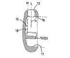
- FIG. 2 is a vertical cross-sectional view of the cord end mounting tool.
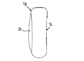
- FIG. 3 is a side view of the cord end attachment tool.
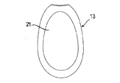
- FIG. 4 is a plan view of the cord end attachment tool.
- FIG. 5 is a rear view of the cord end attachment tool.
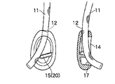
- FIG. 6 is an explanatory view showing a state in which the string is passed through the string end portion mounting tool.
- FIG. 7 is a cross-sectional view showing a state in which a string is tied to the string end attachment tool.
- FIG. 8 is a front view showing a state in which a string is tied to the string end attachment tool.
- FIG. 9 is an explanatory view showing a usage state of the cord end attachment tool.
- FIG. 1 is a front view of a string end fitting device showing an embodiment of the present invention.
- FIG. 2 is a vertical cross-sectional view of the cord end mounting tool.
- FIG. 10 is a front view of the string end part installation tool which shows another embodiment of the same string end part installation tool.
- FIG. 11 is a longitudinal cross-sectional view of the cord end attachment tool.
- FIG. 12 is a side view of the cord end attachment tool.
- FIG. 13 is a plan view of the cord end attachment tool.
- FIG. 14 is a rear view of the cord end attachment tool.
- FIG. 15 is an overall perspective view showing an example of a conventional cord end attachment tool.
- FIG. 16 is a longitudinal cross-sectional view which shows an example of the conventional string end part mounting tool.
- the present invention includes a string insertion opening and a string insertion opening that communicates with the string insertion opening and accommodates a knot of a string opened on one side of a flat wearing tool body and a projection capable of holding an extra end of the knot of the string. Since it is provided, the knot's extra end is fixed, there is no possibility of play or looseness in the string itself, and the whole can be made compact and thin.
- FIG. 1 is a front view of a cord end mounting tool showing an embodiment of the present invention
- FIG. 2 is a longitudinal sectional view of the cord end mounting tool of the present invention
- FIG. 3 is a cord end mounting tool of the present invention. It is a side view.
- the cord end attachment tool 10 is for storing the end portion of the cord 11 provided for tightening a part of clothes, a storage bag or the like, and fixing the cord 11 in a retaining state.
- a recess 14 and a projection 15 formed in the storage recess 14 capable of holding the surplus end 11b of the knot of the string are provided.
- the storage recess 14 is formed in a substantially oval shape as shown in FIG. Further, among the inner walls forming the storage recess 14, the angle ⁇ at which the first inner wall 16 where the string insertion port 12 faces the storage recess 14 intersects the virtual axis L of the string insertion port 12 is less than 90 degrees. In the present embodiment, for example, it is formed at 85 degrees. Furthermore, the second inner wall 17 formed at a position facing the string insertion opening 12 in the inner wall forming the storage recess 14 is formed in parallel with the first inner wall 16 or inclined in the direction of expanding in the opening direction. Has been.
- the protrusion 15 is at least one rib 20 erected from a part of the bottom wall inner side 18 and the inner wall that form the storage recess 14 of the mounting tool body 13 in the present embodiment.
- the rib 20 intersects the virtual axis L of the string insertion opening 12 at an acute angle ⁇ . That is, the rib 20 inclines in the direction which the front-end
- the rib 20 is formed in parallel with the first inner wall 16.
- the rib 20 is formed at a position closer to the second inner wall 17 than the first inner wall 16.
- the inner side 18 of the bottom wall forming the storage recess 14 has a deep region 19 that is further retracted from the virtual extension line M of the string insertion port 12.
- the mounting tool body 13 is formed of a synthetic resin, for example, polyacetal or the like, and has a flat and substantially oval shape as a whole, and has a storage recess 14 opened on one side surface and a recess 21 on the other side surface.
- the storage recess 14 and the recess 21 can facilitate the operation when the mounting tool body 13 is picked with a finger.
- the opening end of the string insertion port 12 is slightly expanded, facilitating work when the string 11 is inserted.
- FIG. 6 is an explanatory view showing a state in which the string is passed through the string end fitting device of the present invention
- FIG. 7 is a sectional view showing a state in which the string is tied
- FIG. 8 is a front view showing a state in which the string is tied.
- the second inner wall 17 is also inclined parallel to the first inner wall 16 or in the direction of expanding in the opening direction, the tip of the string 11 is not caught and can be pulled out of the storage recess 14.
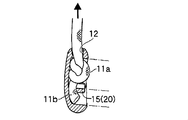
- the knot 11a is stored between the first inner wall 16 and the rib 20 in the storage recess 14 when the string is pulled up in the direction of the string insertion port 12.
- the first inner wall 16 intersects the virtual axis L at an angle ⁇ of less than 90 degrees, the knot 11a is drawn in the direction toward the bottom wall inner side 18 and can be stored compactly.
- the surplus end 11 b is nipped and fixed between the rib 20 and the second inner wall 17.
- FIG. 9 is an explanatory view showing a usage state of the string end fitting device of the present invention.
- the present invention can be applied to apparel fastening parts such as outer hoods and fastening parts using strings such as backpacks and shoes.
- FIG. 10 is a front view of a cord end fitting device showing another embodiment of the cord end fitting device of the present invention
- FIG. 11 is a longitudinal sectional view of the cord end fitting device of the present invention
- FIG. 12 is a cord of the present invention. It is a side view of an edge part mounting tool.
- the structure of the string end fitting 30 is the same as that of the first embodiment because the structure of the string insertion port 12, the storage recess 14, the first inner wall 16, the second inner wall 17, the bottom wall inner side 18, and the deep region 19 is the same. A number is attached and explanation is omitted.
- the protrusion 15 is a columnar body 32 erected from the bottom wall inner side 18 that forms the storage recess 14 of the mounting tool main body 31.
- the columnar body 32 may be inclined in parallel to the first inner wall 16 and the second inner wall 17.
- the columnar body 32 is erected from the bottom wall inner side 18 of the storage recess 14 and is formed independently from the surrounding wall surface.
- the columnar body 32 is formed closer to the second inner wall 17 than the string insertion port 12.
- the cord end attachment tool 30 configured as described above, after making a knot 11a on the cord 11 inserted from the cord insertion opening 12, pulls the cord 11 upward and pulls the knot 11a by the slope effect of the first inner wall 16. While being arranged in the storage recess 14 between the first inner wall 16 and the columnar body 32, the extra end 11b of the string 11 is pushed between the columnar body 32 and the second inner wall 17 so as to be wound around the columnar body 32, and is fastened. Attach.
Landscapes
- Engineering & Computer Science (AREA)
- General Engineering & Computer Science (AREA)
- Mechanical Engineering (AREA)
- Workshop Equipment, Work Benches, Supports, Or Storage Means (AREA)
- Decoration Of Textiles (AREA)
Abstract
衣服や収納袋等の一部を緊締するために設けられた紐の端部を内部に収納し、抜け止め状態で固着する紐端部装着具であって、紐自体の通過が可能であるとともに紐の結び目が通過できない紐挿入口と、前記紐挿入口に連通するとともに、扁平な装着具本体の一側面に開口した紐の結び目を収納可能な収納凹部と、紐の結び目の余端を狭持可能な前記収納凹部内に形成された突起とを備えたので、結び目の余端を狭持固定できる。また、薄型にできるとともに、表面側から紐端部を覆い隠すことができる。
Description
この発明は、衣服や収納袋等の開口部を緊締するために設けられた紐の端部を内部に収納し、抜け止め状態で固着する紐端部装着具に関するものである。
図15は、従来の紐端部装着具の一例を示す全体斜視図、図16は、従来の紐端部装着具の一例を示す縦断面図である。ここで、紐端部装着具1は、有底の筒状体2の底部に紐3を挿通可能な挿通口4を設け、この挿通口4から挿通した紐3の端部に結び目5を作った後、筒状体2の内部に収納して、外部から結び目が目立たないようにしたものである。筒状体2は、円筒に限らず、角筒体であってもよい。
また、引用文献1に示すものは、筒状体の開口部にヒンジ片で取付けられた蓋を設け、結び目を筒状体の内部に収納した後、蓋を閉じて外部から結び目を完全に見えないように構成したものである。
(特許文献1)。
(特許文献1)。
しかし、従来の紐端部装着具は、紐端部の結び目の余り部分が固定されておらず、紐自体に遊びや緩みが生じ易いと云う欠点が存在した。
また、結び目を収納する筒状体が厚みを有するために、見映えが悪いと云った不都合が存在した。
更に、図15、16に示す従来の紐端部装着具では、使用時に紐端部の結び目が剥き出しであり、開放端から飛び出す虞れがあった。また、筒状体の開放端から結び目が見え、外観上好ましくなかった。
また、結び目を収納する筒状体が厚みを有するために、見映えが悪いと云った不都合が存在した。
更に、図15、16に示す従来の紐端部装着具では、使用時に紐端部の結び目が剥き出しであり、開放端から飛び出す虞れがあった。また、筒状体の開放端から結び目が見え、外観上好ましくなかった。
この発明は、上記したような不都合を解消する為になされたもので、紐の結び目を凹部に収納し、結び目の余端を収納凹部内に形成された突起で狭持して緩み止めとするとともに、全体をコンパクトで目立たない紐端部装着具を提供するものである。
この発明は、衣服や収納袋等の一部を緊締するために設けられた紐の端部を内部に収納し、抜け止め状態で固着する紐端部装着具であって、紐自体の通過が可能であるとともに紐の結び目が通過できない紐挿入口と、前記紐挿入口に連通するとともに、扁平な装着具本体の一側面に開口した紐の結び目を収納可能な収納凹部と、紐の結び目の余端を狭持可能な前記収納凹部内に形成された突起とを備えたことを特徴とする紐端部装着具を提供する。
本発明に係る紐端部装着具において、前記収納凹部を形成する内壁の中で、前記紐挿入口が収納凹部に臨む第一内壁は、前記紐挿入口の仮想軸線と90度未満で交わることが好ましい。こうすると、紐の結び目がこの第一内壁に当接しながら上に引かれた際に、収納凹部の底壁方向に向かう分力が生じ、自動的に凹部に収納される。
本発明に係る紐端部装着具において、前記収納凹部を形成する内壁の中で、前記紐挿入口と対向位置に形成された第二内壁は、前記第一内壁と平行または、開口方向に拡開するよう傾斜したことが好ましい。こうすると、紐端部装着具に紐挿入口から紐を挿通して、結び目を作る前段階において、紐の先端が円滑に収納凹部から外に出て結び目を作る操作が容易であるとともに、出来た結び目は、紐を上に引く際に傾斜面によって円滑に凹部に収納することができる。
本発明に係る紐端部装着具において、前記収納凹部を形成する底壁内側は、前記紐挿入口の仮想延長線よりも更に後退した深部領域を有することが好ましい。こうすると、結び目と略同寸法の紐端部の収納域を確保でき、全体の薄型化を実現できる。また、摘み易い形状とすることができる。
本発明に係る紐端部装着具において、前記突起は前記装着具本体の収納凹部を形成する底壁内側および内壁から立設された少なくとも一つのリブであることが好ましい。こうすると、結び目の余端をリブと内壁の隙間に押し込んで留め付けできる。
本発明に係る紐端部装着具において、前記突起は、前記装着具本体の収納凹部を形成する底壁内側から立設された柱状体であることが好ましい。こうすると、結び目の余端を柱状体の周りに巻回して固定できる。
本発明に係る紐端部装着具において、前記収納凹部を形成する内壁の中で、前記紐挿入口が収納凹部に臨む第一内壁は、前記紐挿入口の仮想軸線と90度未満で交わることが好ましい。こうすると、紐の結び目がこの第一内壁に当接しながら上に引かれた際に、収納凹部の底壁方向に向かう分力が生じ、自動的に凹部に収納される。
本発明に係る紐端部装着具において、前記収納凹部を形成する内壁の中で、前記紐挿入口と対向位置に形成された第二内壁は、前記第一内壁と平行または、開口方向に拡開するよう傾斜したことが好ましい。こうすると、紐端部装着具に紐挿入口から紐を挿通して、結び目を作る前段階において、紐の先端が円滑に収納凹部から外に出て結び目を作る操作が容易であるとともに、出来た結び目は、紐を上に引く際に傾斜面によって円滑に凹部に収納することができる。
本発明に係る紐端部装着具において、前記収納凹部を形成する底壁内側は、前記紐挿入口の仮想延長線よりも更に後退した深部領域を有することが好ましい。こうすると、結び目と略同寸法の紐端部の収納域を確保でき、全体の薄型化を実現できる。また、摘み易い形状とすることができる。
本発明に係る紐端部装着具において、前記突起は前記装着具本体の収納凹部を形成する底壁内側および内壁から立設された少なくとも一つのリブであることが好ましい。こうすると、結び目の余端をリブと内壁の隙間に押し込んで留め付けできる。
本発明に係る紐端部装着具において、前記突起は、前記装着具本体の収納凹部を形成する底壁内側から立設された柱状体であることが好ましい。こうすると、結び目の余端を柱状体の周りに巻回して固定できる。
この発明によれば、衣服や収納袋等の一部を緊締するために設けられた紐の端部を内部に収納し、抜け止め状態で固着する紐端部装着具であって、紐自体の通過が可能であるとともに紐の結び目が通過できない紐挿入口と、前記紐挿入口に連通するとともに、扁平な装着具本体の一側面に開口した紐の結び目を収納可能な収納凹部と、紐の結び目の余端を狭持可能な前記収納凹部内に形成された突起とを備えたので、結び目の余端が固定され、紐自体に遊びや緩みが生じる虞れがない上に、全体を薄型化することができる。また、全体を結び目の大きさと略等しいコンパクトな構成とできる。
本発明は、紐挿入口と紐挿入口に連通し、扁平な装着具本体の一側面に開口した紐の結び目を収納可能な収納凹部と紐の結び目の余端を狭持可能な突起とを備えたので、結び目の余端が固定され、紐自体に遊びや緩みが生じる虞れがない上に、全体をコンパクトに薄型化できる。
図1は、この発明の一実施の形態を示す紐端部装着具の正面図、図2は本発明の紐端部装着具の縦断面図、図3は本発明の紐端部装着具の側面図である。ここで紐端部装着具10は、衣服や収納袋等の一部を緊締するために設けられた紐11の端部を内部に収納し、抜け止め状態で固着するものであって、紐自体の通過が可能であるとともに紐11の結び目が通過できない紐挿入口12と、紐挿入口12に連通するとともに、扁平な装着具本体13の一側面に開口した紐の結び目11aを収納可能な収納凹部14と、紐の結び目の余端11bを狭持可能な前記収納凹部14内に形成された突起15とを備えている。
収納凹部14は、図1等に示すように略小判形に形成されている。また、収納凹部14を形成する内壁の中で、紐挿入口12が収納凹部14に臨む第一内壁16が紐挿入口12の仮想軸線Lと交わる角度αは90度未満である。本実施の形態では、例えば、85度に形成されている。更に、収納凹部14を形成する内壁の中で、紐挿入口12と対向位置に形成された第二内壁17は、第一内壁16と平行または、開口方向に拡開する方向に傾斜して形成されている。
突起15は、本実施の形態では装着具本体13の収納凹部14を形成する底壁内側18および内壁の一部から立設された少なくとも一つのリブ20である。また、リブ20は、図1から明らかな様に紐挿入口12の仮想軸線Lと鋭角βで交わっている。つまり、リブ20は、図1中で先端が紐挿入口12から後退する方向に傾斜している。更に、図2に示す断面では、リブ20は第一内壁16と平行に形成されている。また、リブ20は、第一内壁16より第二内壁17に近い位置に形成されている。更に、リブ20は、単数設ける例を示したが、複数設けてもよい。リブ20を複数設ける場合、それぞれ平行に配置してもよく、対向配置してもよい。
さら、図2に示す様に収納凹部14を形成する底壁内側18は、紐挿入口12の仮想延長線Mよりも更に後退した深部領域19を有している。この深部領域19に結び目11aを収納することにより、薄型化を達成することができる。
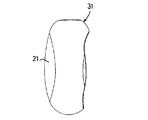
装着具本体13は、合成樹脂、例えば、ポリアセタール等から形成され全体が扁平な略楕円形をしており、一側面に開口した収納凹部14を他側面に窪み21を有している。この収納凹部14及び窪み21は、装着具本体13を指で摘んだ際に操作を容易にすることができる。また、紐挿入口12の開口端部は、僅かに拡開しており、紐11を挿入する際の作業を容易にしている。
次に、以上の様に構成された紐端部装着具10の使用手順について説明する。図6は本発明の紐端部装着具に紐を通す状態を示す説明図、図7は紐を結んだ状態を示す断面図、図8は紐を結んだ状態を示す正面図である。先ず、紐11を紐挿入口12から収納凹部14方向へ挿入する。この際、リブ20は、紐挿入口12の仮想軸線Lと鋭角βに配置されるとともに、第一内壁16と略平行に形成されているので、紐11の先端が引っ掛かることがない。また、第二内壁17も第一内壁16と平行または、開口方向に拡開する方向に傾斜しているので、紐11の先端が引っ掛かることがなく、収納凹部14の外まで引き出すことができる。引き出した紐11に結び目11aを作った後、紐を紐挿入口12方向に引き上げると、結び目11aが収納凹部14内の第一内壁16とリブ20の間に収納される。この際、第一内壁16が、仮想軸線Lと90度未満の角度αで交わるので、結び目11aは底壁内側18方向に引き込まれ、コンパクトに収納できる。更に、余端11bは、リブ20と第二内壁17の間に狭持固定する。このように、結び目11aの余端11bが固定され、紐自体に遊びや緩みが生じる虞れがない。図9は、本発明の紐端部装着具の使用状態を示す説明図である。例えば、外套のフード等のアパレル用締め付け部分や、バックパック、シューズ等の紐を使った締め付け部分に応用することができる。
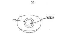
図10は本発明の紐端部装着具の別の実施形態を示す紐端部装着具の正面図、図11は本発明の紐端部装着具の縦断面図、図12は本発明の紐端部装着具の側面図である。ここで、紐端部装着具30は、紐挿入口12、収納凹部14、第一内壁16、第二内壁17、底壁内側18、深部領域19の構成は、実施例1と同様なので、同一番号を付して説明を省略する。本実施の形態において、突起15は装着具本体31の収納凹部14を形成する底壁内側18から立設された柱状体32である。また、図11から明らかなように柱状体32の傾斜は、第一内壁16及び第二内壁17と平行に形成してもよい。柱状体32は、収納凹部14の底壁内側18から立設されるとともに、周囲の壁面から独立して形成されている。 また、柱状体32は、紐挿入口12より第二内壁17に近接して形成されている。
以上の様に構成された紐端部装着具30は、紐挿入口12から挿入した紐11に結び目11aを作った後、紐11を上に引き上げ、第一内壁16の斜面効果により結び目11aを第一内壁16と柱状体32の間の収納凹部14に配置するとともに、紐11の余端11bを柱状体32と第二内壁17の間で、柱状体32の周囲に巻き付ける様に押し込み、留め付けする。
このように、紐11の余端11bを柱状体32周囲に巻き付ける様に押し込み、留め付けることで、紐自体に遊びや緩みが生じる虞れがない。また、全体を結び目11aの大きさと略等しいコンパクトな構成とできる。
上記した実施の形態において、柱状体32を単数設ける例を示したが、これに限ることなく、複数本形成してもよい。
また、本発明は上述の実施例に限定されることなく、特許請求の範囲の記載に基づいて種々の設計変更が可能である。
2010年12月17日に出願された日本特許出願第2010-281665号の明細書、特許請求の範囲、図面及び要約書の全内容をここに引用し、本発明の明細書の開示として、取り入れるものである。
Claims (6)
- 衣服や収納袋等の一部を緊締するために設けられた紐の端部を内部に収納し、抜け止め状態で固着する紐端部装着具であって、
紐自体の通過が可能であるとともに紐の結び目が通過できない紐挿入口と、
前記紐挿入口に連通するとともに、扁平な装着具本体の一側面に開口した紐の結び目を収納可能な収納凹部と、
紐の結び目の余端を狭持可能な前記収納凹部内に形成された突起とを備えたことを特徴とする紐端部装着具。 - 請求項1に記載の紐端部装着具において、
前記収納凹部を形成する内壁の中で、前記紐挿入口が収納凹部に臨む第一内壁は、前記紐挿入口の仮想軸線と90度未満で交わることを特徴とする紐端部装着具。 - 請求項1または2に記載の紐端部装着具において、
前記収納凹部を形成する内壁の中で、前記紐挿入口と対向位置に形成された第二内壁は、前記第一内壁と平行または、開口方向に拡開するよう傾斜したことを特徴とする紐端部装着具。 - 請求項1から3に記載の紐端部装着具において、
前記収納凹部を形成する底壁内側は、前記紐挿入口の仮想延長線よりも更に後退した深部領域を有することを特徴とする紐端部装着具。 - 請求項1から4に記載の紐端部装着具において、
前記突起は、前記装着具本体の収納凹部を形成する底壁内側および内壁から立設された少なくとも一つのリブであることを特徴とする紐端部装着具。 - 請求項1から4に記載の紐端部装着具において、
前記突起は、前記装着具本体の収納凹部を形成する底壁内側から立設された柱状体であることを特徴とする紐端部装着具。
Applications Claiming Priority (2)
| Application Number | Priority Date | Filing Date | Title |
|---|---|---|---|
| JP2010281665A JP2012125499A (ja) | 2010-12-17 | 2010-12-17 | 紐端部装着具 |
| JP2010-281665 | 2010-12-17 |
Publications (1)
| Publication Number | Publication Date |
|---|---|
| WO2012081426A1 true WO2012081426A1 (ja) | 2012-06-21 |
Family
ID=46244534
Family Applications (1)
| Application Number | Title | Priority Date | Filing Date |
|---|---|---|---|
| PCT/JP2011/077985 Ceased WO2012081426A1 (ja) | 2010-12-17 | 2011-12-02 | 紐端部装着具 |
Country Status (2)
| Country | Link |
|---|---|
| JP (1) | JP2012125499A (ja) |
| WO (1) | WO2012081426A1 (ja) |
Citations (2)
| Publication number | Priority date | Publication date | Assignee | Title |
|---|---|---|---|---|
| JPS6451412U (ja) * | 1987-09-25 | 1989-03-30 | ||
| JPH0545290U (ja) * | 1991-11-25 | 1993-06-18 | フルヤ工業株式会社 | ストラツプコネクター |
-
2010
- 2010-12-17 JP JP2010281665A patent/JP2012125499A/ja active Pending
-
2011
- 2011-12-02 WO PCT/JP2011/077985 patent/WO2012081426A1/ja not_active Ceased
Patent Citations (2)
| Publication number | Priority date | Publication date | Assignee | Title |
|---|---|---|---|---|
| JPS6451412U (ja) * | 1987-09-25 | 1989-03-30 | ||
| JPH0545290U (ja) * | 1991-11-25 | 1993-06-18 | フルヤ工業株式会社 | ストラツプコネクター |
Also Published As
| Publication number | Publication date |
|---|---|
| JP2012125499A (ja) | 2012-07-05 |
Similar Documents
| Publication | Publication Date | Title |
|---|---|---|
| US8714358B2 (en) | Earphone protector device | |
| JP5100539B2 (ja) | 収納袋 | |
| JP5219108B2 (ja) | ゴルフクラブヘッドカバー | |
| JP4648801B2 (ja) | 紐止具 | |
| WO2012081426A1 (ja) | 紐端部装着具 | |
| KR200429275Y1 (ko) | 서랍식 포장상자 | |
| KR101064373B1 (ko) | 종이 꽃바구니 | |
| JP3982884B2 (ja) | 紐類の端部カバー | |
| JP3193408U (ja) | 工具差し | |
| US20210009340A1 (en) | Multifunctional shoe accessory | |
| KR200443346Y1 (ko) | 국기 보관용기 | |
| KR200286615Y1 (ko) | 전개식 개폐구조를 갖는 칫솔걸이 | |
| JP2006158355A (ja) | 釣竿収納ケース | |
| CN211323037U (zh) | 一种香烟盒 | |
| US8869976B1 (en) | Storage case for whistle | |
| JP3211876U (ja) | キーケース | |
| JP3088638U (ja) | 傘 | |
| JP2576826Y2 (ja) | 魚釣用リールケース | |
| JP2014046578A (ja) | ペンホルダー付の手帳カバー | |
| JP2515840Y2 (ja) | 釣 竿 | |
| KR200260378Y1 (ko) | 문을 측면까지 여는 수납장 | |
| JP3188952U (ja) | タブレットケース | |
| JP2012217540A (ja) | コードストッパー | |
| KR200199987Y1 (ko) | 치간 치솔 | |
| KR200323879Y1 (ko) | 핸드폰용 손잡이 끈의 체결구 고정장치. |
Legal Events
| Date | Code | Title | Description |
|---|---|---|---|
| 121 | Ep: the epo has been informed by wipo that ep was designated in this application |
Ref document number: 11849207 Country of ref document: EP Kind code of ref document: A1 |
|
| NENP | Non-entry into the national phase |
Ref country code: DE |
|
| 122 | Ep: pct application non-entry in european phase |
Ref document number: 11849207 Country of ref document: EP Kind code of ref document: A1 |