WO2012081077A1 - ダイナミックダンパ - Google Patents
ダイナミックダンパ Download PDFInfo
- Publication number
- WO2012081077A1 WO2012081077A1 PCT/JP2010/072393 JP2010072393W WO2012081077A1 WO 2012081077 A1 WO2012081077 A1 WO 2012081077A1 JP 2010072393 W JP2010072393 W JP 2010072393W WO 2012081077 A1 WO2012081077 A1 WO 2012081077A1
- Authority
- WO
- WIPO (PCT)
- Prior art keywords
- rolling surface
- rolling
- inertial mass
- mass body
- dynamic damper
- Prior art date
- Legal status (The legal status is an assumption and is not a legal conclusion. Google has not performed a legal analysis and makes no representation as to the accuracy of the status listed.)
- Ceased
Links
Images



Classifications
-
- F—MECHANICAL ENGINEERING; LIGHTING; HEATING; WEAPONS; BLASTING
- F16—ENGINEERING ELEMENTS AND UNITS; GENERAL MEASURES FOR PRODUCING AND MAINTAINING EFFECTIVE FUNCTIONING OF MACHINES OR INSTALLATIONS; THERMAL INSULATION IN GENERAL
- F16F—SPRINGS; SHOCK-ABSORBERS; MEANS FOR DAMPING VIBRATION
- F16F15/00—Suppression of vibrations in systems; Means or arrangements for avoiding or reducing out-of-balance forces, e.g. due to motion
- F16F15/10—Suppression of vibrations in rotating systems by making use of members moving with the system
- F16F15/14—Suppression of vibrations in rotating systems by making use of members moving with the system using masses freely rotating with the system, i.e. uninvolved in transmitting driveline torque, e.g. rotative dynamic dampers
- F16F15/1485—Suppression of vibrations in rotating systems by making use of members moving with the system using masses freely rotating with the system, i.e. uninvolved in transmitting driveline torque, e.g. rotative dynamic dampers the rotation being unlimited with respect to driving means
Definitions
- the present invention relates to a dynamic damper that is attached to a rotating member to attenuate or absorb the torque fluctuation or torsional vibration.
- a rotating member such as a crankshaft of an engine mounted on a vehicle, an input shaft or a drive shaft of a transmission, or a member that is attached to and rotates together with the crankshaft is an excitation force (or forcing force) from the engine. It is known that it causes inherent torsional vibrations around its axis. In order to reduce the torsional vibration, in the rotational speed region of the rotating member where the torsional vibration becomes large or in the rotational speed region of the rotating member where the torsional vibration and the period of the explosion rotation speed of the engine cylinder tend to resonate, A dynamic damper is known which is attached to a rotating member and absorbs or attenuates torsional vibration. An example of such a dynamic damper is described in Japanese Patent Laid-Open No. 2000-18329.
- a dynamic damper described in Japanese Patent Laid-Open No. 2000-18329 includes a rolling chamber formed in a flywheel main body, a curved rolling surface formed on an inner wall surface of the rolling chamber, and rotation of the flyhole. And a damper mass that rolls on the rolling surface in accordance with fluctuation or torsional vibration.
- a centrifugal force is generated in the damper mass, and the centrifugal force is pressed against the outer peripheral rolling surface in the radial direction of the flyhole, and when the rotational fluctuation or torsional vibration occurs in the flyhole, Is configured to absorb or dampen rotational fluctuations or torsional vibrations of a predetermined order equal to the reciprocating order by reciprocating while rolling on the rolling surface.
- Japanese Patent Application Laid-Open No. 2007-139017 describes a device for attenuating the pendulum motion of a pendulum type structure such as a ropeway or gondola lift suspended from a rope or the like suspended between columns.
- the apparatus includes a casing having a spherical rolling surface and a plurality of spherical rolling elements accommodated therein so as to be capable of rolling.
- each rolling element attenuates or absorbs the swing of the pendulum structure by rolling in a direction opposite to the swinging direction of the pendulum structure by the inertial force.
- the rolling elements are configured to generate a damping force that attenuates the rolling of the rolling elements by rolling in the opposite directions.
- the damper mass described in Japanese Patent Laid-Open No. 2000-18329 is pressed against the rolling surface by the centrifugal force generated with the rotation of the flyhole. For this reason, the pressure due to the centrifugal force generated in the damper mass, that is, the stress in the direction of compressing the rolling surface, acts on the rolling surface in contact with the damper mass. Further, according to the configuration described in Japanese Patent Laid-Open No. 2000-18329, the damper mass and the rolling surface are in contact with each other at one location, so that the pressure and compressive stress due to the centrifugal force of the damper mass are concentrated at the one location. It will be. Therefore, in the configuration described in Japanese Patent Application Laid-Open No. 2000-18329, the vibration performance of the dynamic damper is caused by deformation of the rolling surface or change of the reciprocating motion order of the damper mass due to deformation of the rolling surface. May decrease.
- the present invention has been made paying attention to the above technical problem, and provides a dynamic damper capable of dispersing centrifugal force generated in an inertial mass acting on a rolling surface and compressive stress on the rolling surface. It is for the purpose.
- an inertial mass body that reciprocates in response to torsional vibration of the rotating member is accommodated in an accommodating chamber provided at a location away from the rotation center of the rotating member that vibrates torsionally.
- a dynamic damper in which a rolling surface on which the inertial mass body reciprocates is formed on the inner wall surface of the storage chamber, the centrifugal force generated in the inertial mass body with the rotation of the rotating member is The inertial mass body is in contact with the rolling surface at a plurality of locations so as to be dispersed with respect to the moving surface, and is in contact with the rolling surface at a plurality of locations according to the torsional vibration of the rotating member.
- the moving surface is configured to reciprocate.
- the inertial mass body is configured to disperse the centrifugal force generated in the inertial mass body with respect to the rolling surface as the rotating member rotates.
- the rolling surface is configured to reciprocate in response to torsional vibration of the rotating member while contacting at a plurality of locations in the circumferential direction of the rolling surface and contacting the rolling surface at a plurality of locations. It is a dynamic damper characterized by being made.
- the inertial mass body includes a mass part having a predetermined mass, a plurality of rolling parts that roll on the rolling surface, and the rolling part as the mass part. And a support portion for supporting the dynamic damper.
- this invention WHEREIN: While the said support part supports these rolling parts to the said mass part, it is arrange
- the inertial mass body distributes the centrifugal force which arose in the inertial mass body with rotation of the rotation member to the rolling surface.
- the dynamic damper is configured to be in contact with the rolling surface at at least two locations in the circumferential direction of the rolling surface.
- the inertial mass body is configured to come into contact with the rolling surface at a plurality of locations and to reciprocate the rolling surface while contacting at the plurality of locations. It is possible to prevent or suppress the concentration of the centrifugal force and load of the inertial mass body at one place and the occurrence of excessive surface pressure at one place. In addition, when the inertial mass body reciprocates on the rolling surface, the centrifugal force or load of the inertial mass body concentrates in the circumferential direction of the rolling surface that passes through the one place, or excessive surface pressure is generated. Can be prevented or suppressed.
- the rolling surface is recessed or It is possible to prevent or suppress deformation such as occurrence, and to prevent or suppress a decrease in vibration damping performance of the dynamic damper due to deformation of the rolling surface. Since the number of locations where the inertia mass body and the rolling contact surface are increased, the inertia mass body is reduced, for example, in order to reduce the centrifugal force and load acting on the rolling contact surface. Or the inertial mass of the inertial mass body can be secured.
- inertial mass is comprised so that a rolling surface may be contacted in several places in the circumferential direction of a rolling surface
- the centrifugal force of the inertia mass body can be dispersed in the circumferential direction of the rolling surface.
- an inertial mass body is provided with the several rolling part, Therefore The centrifugal of the inertial mass body which acts on a rolling surface is carried out.
- the pressure on the rolling surface such as force and load can be dispersed, thereby preventing or suppressing the deformation of the rolling surface and preventing or suppressing the deterioration of the damping performance due to the deformation of the rolling surface. be able to.
- since there are multiple contact points between the inertial mass body and the rolling surface when the inertial mass body rolls on the rolling surface, it is compared with the case where the contact point between the inertial mass body and the rolling surface is one location.
- the inertial mass body when the inertial mass body reciprocates on the rolling surface by being in contact with the rolling surface at a plurality of locations, the inertial mass body can be prevented or suppressed from tilting, and the inertial mass body can be stabilized. Can reciprocate in posture. Furthermore, since the function is divided at each part, the rolling part can be formed with a small diameter, that is, the inertia moment of the rolling part can be reduced to facilitate the rotation. Moreover, since the mass part should just be comprised so that it may mainly have an inertial mass, the shape and gravity center position can be designed freely.
- a support part supports a some rolling part to a mass part, and at predetermined intervals in the reciprocating motion direction of an inertial mass body. Therefore, the rolling portions can be arranged in the circumferential direction of the rolling surface and the rotation axis direction of the rotating member. Therefore, the number of contact points between the inertial mass body and the rolling surface increases, and the centrifugal force and load of the inertial mass body acting on the rolling surface can be dispersed. Further, it is possible to prevent or suppress deformation of the rolling surface in advance and prevent or suppress a decrease in vibration damping performance due to deformation of the rolling surface.
- the inertial mass body is configured to contact at least two places in the circumferential direction of the rolling surface. Therefore, compared with the case where the inertial mass body contacts the rolling surface at, for example, three places, the inertial mass body and the rolling surface are not dependent on the arrangement of the support portion that supports the rolling portion on the mass portion. Can be contacted. More specifically, when the inertia mass body is brought into contact with the rolling surface at three locations, the assembly accuracy of the support portion that supports the rolling portion to the mass portion is required as compared with the case where the inertia mass body is contacted at two locations.
- the assembly accuracy can be reduced as compared with the case where the inertia mass body and the rolling surface are brought into contact with each other at three locations, thereby reducing the manufacturing cost and the number of parts.
- the rotation center axis of each rolling part associated with the reciprocating motion of the inertial mass body is compared with the case where the inertia mass body is brought into contact at the three locations.
- FIG. 2 is a sectional view taken along line II-II ′ shown in FIG. 1. It is a figure which shows typically the structure of the dynamic damper which concerns on this invention which contacts a rolling surface at three places. It is a figure which shows typically the example which improved the structure shown in FIG.
- FIG. 5 is a sectional view taken along line V-V ′ shown in FIG. 4.
- the present invention relates to a dynamic damper that is attached to a rotating rotating member and absorbs or attenuates rotational fluctuation of the rotating member or torsional vibration resulting therefrom. Therefore, the rotating member is a crankshaft of an engine mounted on a vehicle, an input shaft or a drive shaft of a transmission, or a member that is attached to these and rotates integrally therewith.
- a storage chamber is formed at a location away from the rotation center of the rotating member, and an inertia mass body (that is, a damper mass) that reciprocates in the rotating direction of the rotating member is stored therein.
- an inertia mass body that is, a damper mass
- an arc-shaped rolling surface having a constant curvature can be formed on the inner wall surface of the storage chamber, and the above-described inertial mass is applied to the rolling surface according to the rotational fluctuation of the rotating member or torsional vibration caused by this.
- the body reciprocates.
- the rolling surface may be configured in an elliptical shape or a cycloid shape whose curvature gradually changes, and the center of instantaneous curvature in the movement trajectory of the inertial mass body that reciprocates on the rolling surface is the inertial mass body. You may comprise so that it may change according to the magnitude
- the inertial mass body mainly rolls when it is in contact with the rolling surface and has the above-mentioned rotational fluctuations and torsional vibrations in order to generate inertial force.
- the mass portion only needs to be configured so as to generate mainly an inertial force, and therefore the shape thereof may be arbitrary.
- the rolling part may be configured to have a small diameter so that the rolling surface can easily roll, in other words, the moment of inertia is reduced.
- the supporting part should just be comprised so that a rolling part may support a rolling surface with respect to a mass part so that rolling is possible.
- the inertial mass body is configured to contact the rolling surface at a plurality of locations in the circumferential direction of the rolling surface.
- the inertia mass body includes at least two rolling portions, which are arranged on the mass portion at a predetermined interval in the circumferential direction of the rolling surface, and are respectively supported via the support portions.
- the inertial mass body is configured to come into contact with the rolling surface at a plurality of locations in the circumferential direction. Concentration of centrifugal force and load of the mass body can be prevented or suppressed.
- the centrifugal force generated in the inertial mass body can be dispersed in the circumferential direction of the rolling surface, when the centrifugal force or load of the inertial mass body acts on one place with the rolling surface In comparison, it is possible to prevent or suppress deformation such as a dent on the rolling surface and a rut. And the fall of the damping performance of the dynamic damper resulting from the deformation
- the inertial mass body is configured to contact at least two locations in the circumferential direction of the rolling surface, the number of parts and assembly accuracy can be reduced compared to a configuration configured to contact at three locations. This can reduce the manufacturing cost.
- FIG. 3 schematically shows the configuration of the dynamic damper according to the present invention which contacts the rolling surface at three locations.
- FIG. 3 shows a state in which one dynamic damper 1 is viewed from a direction perpendicular to the rotating surface of the rotating member 2 to which the dynamic damper 1 is attached.
- the dynamic damper 1 includes, for example, a crankshaft of an engine of a vehicle, an input shaft or a driveshaft of a transmission to be controlled, or a rotating member 2 that is attached to these and rotates integrally therewith, and rotation of the rotating member 2
- the storage chamber 3 formed in a hollow cylindrical shape, for example, at a location away from the center, the arcuate rolling surface 4 of constant curvature formed on the inner wall surface of the storage chamber 3, and the storage chamber 3,
- An inertial mass body (damper mass) 5 that reciprocates on the rolling surface 4 in response to rotational fluctuations of the rotating member 2 or torsional vibration resulting therefrom is configured as a main component.
- the inertia mass body 5 includes a mass portion 6 having a predetermined mass so as to generate mainly an inertial force, and a plurality of rolling portions 7 configured to come into contact with the rolling surface 4 and allow the rolling surface 4 to roll. And a support part that supports the mass part 6 so that the rolling part 7 can roll with respect to the rolling surface 4.
- the mass portion 6 is a portion corresponding to a substantial damper mass, and can be formed of, for example, a metallic material having a predetermined rigidity and mass or a synthetic resin material such as rubber.
- the mass portion 6 only needs to have an inertial mass or an inertial force for absorbing or attenuating the rotational fluctuation of the rotating member 2 or the torsional vibration resulting therefrom, and therefore the shape thereof is arbitrary. Good. Therefore, when the inertia mass body 5 rolls on the rolling surface 4 and is disposed at the most bulged position or the outermost peripheral position in the storage chamber 3, the center of gravity of the mass portion 6 is the outer peripheral side in the radial direction of the rotating member 2.
- the center of gravity of the mass portion 6 may be configured to be decentered with respect to the geometric center of the mass portion 6 so as to be disposed at the center.
- the rolling part 7 is supported by the mass part 6 via a support part (not shown) so that it can roll with respect to the rolling surface 4.
- the rolling unit 7 rotates the rolling surface 4 according to the rotational variation or torsional vibration, thereby rotating the mass unit 6 to rotate the rotating member 2. Reciprocating in the direction. Therefore, it is preferable to form the rolling part 7 with a relatively small diameter so that the moment of inertia becomes small.
- the mass part 6 acting on the rolling surface 4 and the support are provided. Centrifugal force generated in the part and these loads can be dispersed in the circumferential direction of the rolling surface 4.
- the support part may be configured to bring the rolling part 7 into contact with the rolling surface 4 and to support the rolling part 7 on the mass part 6 so as to roll on the rolling surface 4. Therefore, for example, a shaft (not shown) provided integrally on the rotation axis of the rolling part 7 and a bearing (not shown) provided on the mass part 6 and rotatably supporting the shaft are configured. be able to.
- the three rolling parts 7 are respectively supported by the mass part 6 via the support part at a predetermined interval in the rotational direction of the rotating member 2 or the circumferential direction of the rolling surface 4.
- the shafts of the support portions are arranged in parallel to each other and in parallel to the rotation axis of the rotating member 2.
- the rolling part 7 is formed in a small diameter so that the moment of inertia becomes small, the rolling part 7 easily rolls on the rolling surface 4 and improves the damping performance of the inertia mass body 5. Can be made. However, if the number of the rolling parts 7 provided in the mass part 6 is increased, each rolling part 7 must be arranged so as to contact the rolling surface 4 in the same manner. In some cases, high assembly accuracy may be required.
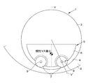
- FIG. 1 schematically shows the configuration of a dynamic damper according to the present invention that contacts the rolling surface at two locations.
- the example shown here is an example in which the two rolling parts 7 are supported by the mass part 6 via the support part at a predetermined interval in the rotational direction of the rotating member 2 or the circumferential direction of the rolling surface 4.
- a mass portion 6 having a semicircular arc surface having a constant curvature is accommodated in the storage chamber 3 in which the rolling surface 4 having a constant curvature is formed.
- the arc surface of the mass portion 6 faces the rolling surface 4 when the rotating member 2 rotates and the inertia mass body 5 rolls and moves to the outermost bulging position or the outermost circumferential position in the storage chamber 3. It is arranged.
- rolling portions 7 are disposed on both ends of the center of the arc surface of the mass portion 6, and each rolling portion 7 is supported by the mass portion 6 via a support portion. ing.
- the shafts of the respective support portions are arranged in parallel with each other and in parallel with the rotation axis of the rotation member 2.
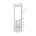
- FIG. 2 is a cross-sectional view taken along the line II-II ′ shown in FIG.
- the support part 8 should just be comprised so that the rolling part 7 may contact the rolling surface 4 as mentioned above, and it may be supported by the mass part 6 so that rolling with respect to the rolling surface 4 is possible. Therefore, the support portion 8 is, for example, a shaft 9 integrated or fixed to the mass portion 6 and a bearing (not shown) that is provided on the rolling portion 7 and supports the shaft 9 coaxially and rotatably with the rolling portion 7. ) And can be configured. Further, for example, it may be constituted by a shaft 9 provided integrally on the rotation axis of the rolling part 7 and a bearing (not shown) provided on the mass part 6 and rotatably supporting the shaft 9. it can. Furthermore, when the plurality of rolling portions 7 are supported by the mass portion 6, the shafts 9 of the respective support portions 8 are arranged so as to be parallel to each other and parallel to the rotation axis of the rotating member 2.
- one inertial mass body 5 includes two rolling portions 7 in the circumferential direction of the rolling surface 4. There are two places where 5 and the rolling surface 4 come into contact.
- the shafts 9 of the respective support portions 8 can be easily arranged as compared with the case where the inertial mass body 5 and the rolling surface 4 are brought into contact at three places as shown in FIG. Therefore, the assembly accuracy of the support portion 8 can be reduced, and thereby the manufacturing cost and the number of parts can be reduced.
- the curvature in the movement trajectory of each rolling part 7 and its instantaneous curvature center and the curvature of the rolling surface 4 and its instantaneous curvature center can be easily made the same or substantially the same, and stable vibration control performance is obtained. be able to.
- the centrifugal force and load of the inertial mass body 5 acting on the rolling surface 4 can be dispersed compared to the case where the inertial mass body 5 and the rolling surface 4 are in contact at one place. It is possible to prevent or suppress deformation of the moving surface 4 such as a dent or rudder, and to prevent or suppress a decrease in vibration damping performance of the dynamic damper 1 due to deformation of the rolling surface 4.
- the inertial mass body 5 Since the inertial mass body 5 is in contact with the rolling surface 4 at two locations, it can reciprocate in a stable posture when reciprocating, and the inertial mass body 5 collides with the storage chamber 3. In addition, it is possible to prevent or suppress the generation of abnormal noise or noise due to a collision. Further, in the example shown in FIG. 1, since the two rolling parts 7 are in contact with the rolling surface 4, the inertial mass body 5 can maintain a relatively large inertial force or inertial mass.
- FIG. 4 schematically shows an example in which the configuration shown in FIG. 1 is improved.
- the example shown here is an example which provided four rolling parts in the mass part via two support parts. More specifically, in the example shown in FIG. 4, for example, the mass portion 6 has a semicircular arc surface with a constant curvature, and both sides of the arc surface sandwich the central portion in the circumferential direction. Moreover, the two rolling parts 7 are supported by the mass part 6 via one support part. The two rolling portions 7 are provided at both ends of the shaft 9, respectively. Further, the shafts 9 of the respective support portions are arranged so as to be parallel to each other and parallel to the rotation axis of the rotating member 2.
- FIG. 5 is a cross-sectional view taken along the line V-V ′ shown in FIG.
- the two rolling portions 7 are arranged so as to sandwich the mass portion 6, and the rolling surface 4 is supported by the mass portion 6 via the support portion 8 so as to be able to roll.
- the support portion 8 may be configured so that the rolling portion 7 can support the rolling surface 4 on the mass portion 6 such that the rolling surface 4 can roll.
- support portions 8 are provided at two locations in the circumferential direction of the rolling surface 4 with respect to the mass portion 6. It is comprised so that the two rolling parts 7 may be supported, respectively.
- the two rolling parts 7 supported by the one supporting part 8 have the same rotational axis. Therefore, in FIGS. 4 and 5, apparently, the inertial mass body 5 comes into contact with two places in the circumferential direction of the rolling surface 4 and comes into contact with two places in the rotation axis direction of the rotating member 2. That is, since the inertial mass body 5 contacts the rolling surface 4 at four locations, the centrifugal force and the load generated on the mass portion 6 and the support portion 8 acting on the rolling surface 4 are the same as those shown in FIGS.
- the rolling surface is compared with the case where one inertial mass body contacts one location of the rolling surface.
- the posture can be stabilized, and the collision between the inertial mass body and the storage chamber, and the generation of abnormal noise and noise associated with the collision can be prevented or suppressed.
- the inertial mass body can easily reciprocate on the rolling surface in response to rotational fluctuations and torsional vibrations of the rotating member, and the damping performance of the dynamic damper can be improved. Can be improved. Further, the inertia mass body can ensure a relatively large inertia force or inertia mass.
Landscapes
- Engineering & Computer Science (AREA)
- General Engineering & Computer Science (AREA)
- Physics & Mathematics (AREA)
- Acoustics & Sound (AREA)
- Aviation & Aerospace Engineering (AREA)
- Mechanical Engineering (AREA)
- Vibration Prevention Devices (AREA)
Abstract
転動面に作用する慣性質量体に生じた遠心力や慣性質量体の荷重を分散することができるダイナミックダンパを提供する。 捩り振動する回転部材2の回転中心から離れた箇所に設けられた収容室3に、回転部材2の捩り振動に応じて往復運動する慣性質量体5を収容するとともに、その収容室3の内壁面に慣性質量体5が往復運動する転動面4が形成されているダイナミックダンパ1において、回転部材2の回転に伴って慣性質量体5に生じた遠心力を転動面4に対して分散するように、慣性質量体5は転動面4に対し複数箇所で接触し、かつ転動面4に複数箇所で接触しながら回転部材2の捩り振動に応じて転動面4を往復運動するように構成されていることを特徴とする。
Description
この発明は、回転部材に取り付けられてそのトルク変動もしくは捩り振動を減衰させ、もしくは吸収するダイナミックダンパに関するものである。
車両に搭載されるエンジンのクランクシャフトや変速機のインプットシャフトあるいはドライブシャフトなど、あるいはこれらに取り付けられてこれらと一体回転する部材などの回転部材は、エンジンからの起振力(もしくは、強制力と呼ばれることがある。)に起因して、その軸心の周りに固有の捩り振動を起こすことが知られている。この捩り振動が大きくなる回転部材の回転数領域や捩り振動とエンジンのシリンダの爆発回転速度の周期とが共振しやすい回転部材の回転数領域において、捩り振動を低減するために、前述したような回転部材に取り付けられて、捩り振動を吸収もしくは減衰させるダイナミックダンパが知られている。そのようなダイナミックダンパの一例が特開2000-18329号公報に記載されている。
特開2000-18329号公報に記載されたダイナミックダンパは、フライホイール本体に形成された転動室と、その転動室の内壁面に形成された曲面形状の転動面と、フライホールの回転変動あるいは捩り振動に伴って転動面を転動するダンパマスとを備えている。そして、フライホールが回転すると、ダンパマスには遠心力が生じ、その遠心力によってフライホールの半径方向で外周側の転動面に押し付けられるとともに、フライホールに回転変動あるいは捩り振動が生じると、ダンパマスが転動面を転動しながら往復運動することにより、その往復運動次数に等しい所定次数の回転変動あるいは捩り振動を吸収もしくは減衰するように構成されている。
なお、特開2007-139017号公報には、支柱間に架け渡されたロープなどに懸垂されるロープウェイやゴンドラリフトなどの振子型の構造物の振子運動を減衰する装置が記載されており、その装置は、球面状の転動面を有するケーシングと、その内部に転動可能に収容された複数の球体形状の転動体とを備えている。そして、振子型構造物が揺動すると、各転動体は、慣性力によって振子型構造物の揺動の方向とは反対方向に転動することにより振子型構造物の揺動を減衰もしくは吸収し、各転動体が互いに接触する部分では、各転動体が互いに逆方向に転動することにより各転動体の転動を減衰する減衰力を発生するように構成されている。
上記のように、特開2000-18329号公報に記載されているダンパマスは、フライホールの回転に伴って生じた遠心力によって転動面に押し付けられる。そのため、ダンパマスに接触する転動面には、ダンパマスに生じた遠心力による圧力、すなわち転動面を圧縮する方向の応力が作用することになる。また、特開2000-18329号公報に記載された構成によれば、ダンパマスと転動面とは一箇所で接触しているので、その一箇所にダンパマスの遠心力による圧力や圧縮応力が集中することになる。したがって、特開2000-18329号公報に記載された構成では、転動面に変形が生じたり、転動面が変形することによりダンパマスの往復運動次数が変化したりしてダイナミックダンパの制振性能が低下する虞がある。
そこで、転動室やダンパマスの数を増加することにより、ダンパマスに生じる遠心力を小さくしたり、転動面に作用する圧力や圧縮応力を分散したりすることが考えられる。しかしながら、フライホールなどの回転部材の大きさを一定とし、転動室やダンパマスの数を増加しようとすると、その増加できる数には自然と限界がある。また、各ダイナミックダンパを小型化して転動室やダンパマスの数を増加しようとすると、吸収あるいは減衰したい回転部材の回転変動や捩り振動次数に対応した往復運動次数で往復運動するダンパマスの慣性質量を確保し難くなる。
特開2007-139017号公報に記載された技術は、複数の球状の質量体をケーシングの内部に自在に設けることにより、これらの質量体の慣性力によって索道の揺れを抑制するとともに、球状の質量体が互いに接触する部分では、各質量体が互いに逆方向に運動することにより各質量体に減衰力を発生させて各質量体の慣性力による移動を制限するための技術である。
この発明は上記の技術的課題に着目してなされたものであり、転動面に作用する慣性質量体に生じた遠心力や転動面に対する圧縮応力を分散することができるダイナミックダンパを提供することを目的とするものである。
上記の目的を達成するために、この発明は、捩り振動する回転部材の回転中心から離れた箇所に設けられた収容室に、前記回転部材の捩り振動に応じて往復運動する慣性質量体を収容するとともに、その収容室の内壁面に前記慣性質量体が往復運動する転動面が形成されているダイナミックダンパにおいて、前記回転部材の回転に伴って前記慣性質量体に生じた遠心力を前記転動面に対して分散するように、前記慣性質量体は前記転動面に対し複数箇所で接触し、かつ前記転動面に複数箇所で接触しながら前記回転部材の捩り振動に応じて前記転動面を往復運動するように構成されていることを特徴とするものである。
また、この発明は、上記の発明において、前記回転部材の回転に伴って前記慣性質量体に生じた遠心力を前記転動面に対して分散するように、前記慣性質量体は前記転動面に対して前記転動面の円周方向における複数箇所で接触し、かつ前記転動面に複数箇所で接触しながら前記回転部材の捩り振動に応じて前記転動面を往復運動するように構成されていることを特徴とするダイナミックダンパである。
さらにまた、この発明は、上記の発明において、前記慣性質量体は、所定の質量を有する質量部と、前記転動面を転動する複数の転動部と、該転動部を前記質量部に支持する支持部とを備えていることを特徴とするダイナミックダンパである。
そして、この発明は、上記の発明において、前記支持部は、前記複数の転動部を前記質量部に支持するとともに、前記慣性質量体の往復運動方向で所定間隔を隔てて配置されることを特徴とするダイナミックダンパである。
そしてまた、この発明は、上記いずれかの発明において、前記回転部材の回転に伴って前記慣性質量体に生じた遠心力を前記転動面に対して分散するように、前記慣性質量体は、前記転動面の円周方向における少なくとも2箇所で前記転動面に接触するように構成されていることを特徴とするダイナミックダンパである。
この発明によれば、慣性質量体は、転動面に対して複数箇所で接触し、かかる複数箇所で接触しながら転動面を往復運動するように構成されているので、転動面のある一箇所に慣性質量体の遠心力や荷重が集中したり、ある一箇所に過大な面圧が生じたりすることを防止もしくは抑制することができる。また、慣性質量体が転動面を往復運動する場合に、上記の一箇所を通る転動面の円周方向に、慣性質量体の遠心力や荷重が集中したり、過大な面圧が生じたりすることを防止もしくは抑制することができる。そのため、転動面のある一箇所およびその一箇所を通る転動面の円周方向に集中して慣性質量体の遠心力が作用する場合に比較して、転動面が凹んだり、わだちが生じたりするなどの変形を防止もしくは抑制できるとともに、転動面の変形に起因するダイナミックダンパの制振性能の低下を防止もしくは抑制することができる。そして、慣性質量体と転動面とが接触する箇所数を増加させるように構成させているので、転動面に作用する上記の遠心力や荷重を低減するために慣性質量体を例えば小さくしたり、分割したりする必要がなく、慣性質量体の慣性質量を確保することができる。
また、この発明によれば、上記の発明による効果と同様の効果に加えて、慣性質量は、転動面の円周方向における複数箇所で転動面に接触するように構成されているので、転動面の円周方向に慣性質量体の遠心力を分散させることができる。そしてこれにより、転動面の変形を防止もしくは抑制できるとともに、転動面の変形に起因するダイナミックダンパの制振性能の低下を防止もしくは抑制することができる。
さらにまた、この発明によれば、上記の発明による効果と同様の効果に加えて、慣性質量体は、複数の転動部を備えていることにより、転動面に作用する慣性質量体の遠心力や荷重などの転動面に対する圧力を分散することができ、これにより転動面の変形を未然に防止もしくは抑制し、転動面の変形に起因する制振性能の低下を防止もしくは抑制することができる。また、慣性質量体と転動面との接触箇所が複数あるので、慣性質量体が転動面を転動する場合に、慣性質量体と転動面との接触箇所が一箇所の場合に比較して、慣性質量体と収容室との衝突や接触などに起因する異音の発生を防止もしくは低減することができる。さらに、複数箇所で転動面に接触していることにより、慣性質量体が転動面を往復運動する場合に、慣性質量体が傾いたりすることを防止もしくは抑制でき、慣性質量体を安定した姿勢で往復運動させることができる。さらにまた、各部で機能を分けるように構成されているので、転動部を小径に形成することが可能になり、すなわち転動部の慣性モーメントを小さくして回転し易くすることができる。また、質量部は主として慣性質量を有するように構成されていればよいので、その形状や重心位置を自由に設計することができる。より具体的には、回転部材が回転して慣性質量体に遠心力が生じて慣性質量体が転動室における最膨出位置あるいは最外周位置に配置された場合に、慣性質量体の重心位置がその幾何学的な中心に対して回転部材の半径方向で外周側に配置されるように、質量部の重心位置を例えば偏心させて設計することができる。その結果、各部で機能が分けられていることにより、慣性質量体が回転部材の捩り振動に応じて転動面を往復運動し易くなり、制振性能を向上させることができる。
そして、この発明によれば、上記の発明による効果と同様の効果に加えて、支持部は、複数の転動部を質量部に支持するとともに、慣性質量体の往復運動方向で所定間隔を隔てて配置されるので、転動面の円周方向および回転部材の回転軸線方向に転動部を配置することができる。そのため、慣性質量体と転動面との接触箇所が多くなり、転動面に作用する慣性質量体の遠心力や荷重などを分散することができる。また、これにより転動面の変形を未然に防止もしくは抑制し、転動面の変形に起因する制振性能の低下を防止もしくは抑制することができる。
そしてまた、この発明によれば、上記いずれかの発明による効果と同様の効果に加えて、慣性質量体はその転動面の円周方向における少なくとも二箇所で接触するように構成されている。そのため、慣性質量体が例えば三箇所で転動面に接触する場合に比較して、転動部を質量部に支持する支持部の配置に因らずに、慣性質量体と転動面とを接触させることができる。より具体的には、慣性質量体を転動面に三箇所で接触させる場合には、二箇所で接触させる場合に比較して転動部を質量部に支持する支持部の組み付け精度が要求される。しかしながら、慣性質量体と転動面とを二箇所で接触させる場合には、三箇所で接触させる場合に比較して、組み付け精度を低減でき、これにより製造コストおよび部品点数を低減することができる。また、慣性質量体を転動面の円周方向で二箇所で接触させると、上記の三箇所で接触させる場合に比較して、慣性質量体の往復運動に伴う各転動部の回転中心軸の移動軌跡における曲率および瞬間曲率中心と転動面の曲率およびその中心を容易に同一あるいはほほ同じすることができ、安定した制振性能を得ることができる。
つぎにこの発明をより具体的に説明する。この発明は、回転する回転部材に取り付けられ、回転部材の回転変動もしくはこれに起因する捩り振動を吸収もしくは減衰するダイナミックダンパに関するものである。したがって、その回転部材は、車両に搭載されるエンジンのクランクシャフトや変速機のインプットシャフトあるいはドライブシャフトなど、あるいはこれらに取り付けられてこれらと一体回転する部材などである。
この発明では、回転部材の回転中心から離れた箇所に収容室が形成されており、その内部に、回転部材の回転方向に往復運動する慣性質量体(すなわち、ダンパマス)が収容されている。収容室の内壁面には、一例として一定曲率の円弧形状の転動面を形成することができ、この転動面を回転部材の回転変動もしくはこれに起因する捩り振動に応じて上記の慣性質量体が往復運動するようになっている。また例えば、転動面は、その曲率が次第に変化するような楕円形状やサイクロイド形状に構成してもよく、転動面を往復運動する慣性質量体の移動軌跡における瞬間曲率中心が、慣性質量体の振幅の大きさに応じて変化するように構成してもよい。慣性質量体は、主として慣性力を生じさせるために、所定の質量を有するように構成された質量部と、主として転動面に接触しかつ上記の回転変動や捩り振動が生じた場合に転動面を転動する複数の転動部と、主として転動部を転動面に対して転動可能に、かつ質量部に対して支持する支持部とを備えている。質量部は、主として慣性力を生じるように構成されていればよく、したがって、その形状は任意であってよい。転動部は、転動面を転動しやすいように、言い換えれば慣性モーメントが小さくなるように小径に構成されていればよい。支持部は、転動部が転動面を転動可能に質量部に対して支持するように構成されていればよい。
したがって、慣性質量体は、転動面に対し、転動面の円周方向における複数箇所で接触するように構成されている。例えば、慣性質量体は、少なくとも二つの転動部を備え、これらが上記の質量部に転動面の円周方向に所定間隔を隔てて配置され、上記の支持部を介してそれぞれ支持されることにより構成することができる。慣性質量体は、回転部材の回転変動もしくはこれに起因する所定次数の捩り振動を吸収もしくは減衰させるためのものであるから、慣性質量体の往復運動次数は、吸収もしくは減衰したい回転部材の回転変動次数に等しくなるように、あるいは回転部材の回転変動次数に近似した値になるように設定することができる。
したがって、このような構成のダイナミックダンパにおいては、慣性質量体は、転動面に対してその円周方向で複数箇所で接触するように構成されているので、転動面のある一箇所に慣性質量体の遠心力や荷重が集中したりすることを防止もしくは抑制することができる。また、慣性質量体に生じた遠心力を転動面の円周方向に分散させることができるので、転動面のある一箇所に集中して慣性質量体の遠心力や荷重が作用する場合に比較して、転動面に凹みが生じり、わだちが生じたりするなどの変形を防止もしくは抑制することができる。そして、上記のような転動面の変形に起因するダイナミックダンパの制振性能の低下を防止もしくは抑制することができる。さらにまた、慣性質量体は転動面の円周方向で少なくとも二箇所で接触するように構成されているので、三箇所で接触するように構成した場合に比較して、部品点数および組み付け精度を低減することができ、これにより製造コストを低減することができる。
より具体的に説明すると、図3に、転動面に対して三箇所で接触するこの発明に係るダイナミックダンパの構成を模式的に示してある。図3には、一つのダイナミックダンパ1を、そのダイナミックダンパ1が取り付けられる回転部材2の回転面に対し、垂直な方向から見た状態を示してある。ダイナミックダンパ1は、制振対象となる例えば車両のエンジンのクランクシャフトや変速機のインプットシャフトあるいはドライブシャフトなど、あるいはこれらに取り付けられてこれらと一体回転する回転部材2と、その回転部材2の回転中心から離れた箇所に例えば中空の円筒形状に形成された収容室3と、収容室3の内壁面に形成された例えば一定曲率の円弧状の転動面4と、収容室3に収容され、回転部材2の回転変動あるいはこれに起因する捩り振動に応じて転動面4を往復運動する慣性質量体(ダンパマス)5とを主要な構成要素として構成されている。
慣性質量体5は、その往復運動次数によって回転部材2の所定次数の捩り振動を吸収もしくは減衰するものであるから、慣性質量体5の往復運動次数は、吸収もしくは減衰したい回転部材2の捩り振動の次数、すなわち回転変動次数に等しくなるように、あるいはその回転変動次数に近似した値になるように設計されている。慣性質量体5は、主として慣性力を生じるように所定の質量を有する質量部6と、転動面4に接触するとともに転動面4を転動可能に構成された複数の転動部7と、転動部7を転動面4に対して転動可能にかつ質量部6に支持する支持部とを備えている。
質量部6は、実質的なダンパマスに相当する部分であり、例えば所定の剛性と質量とを有する金属性材料やゴムなどの合成樹脂材料などによって形成することができる。質量部6は、要は、回転部材2の回転変動やこれに起因する捩り振動を吸収あるいは減衰させるための慣性質量や慣性力を有していればよく、したがって、その形状は任意であってよい。そのため、慣性質量体5が転動面4を転動して収容室3における最膨出位置あるいは最外周位置に配置された場合に、質量部6の重心が回転部材2の半径方向で外周側に配置されるように、質量部6の重心位置を質量部6の幾何学的な中心に対して偏心させるように構成してもよい。
転動部7は、転動面4に対して転動可能に、支持部(図示せず)を介して質量部6に支持されている。転動部7は、回転部材2に回転変動や捩り振動が生じた場合に、その回転変動や捩り振動に応じて転動面4を転動することにより、質量部6を回転部材2の回転方向に往復運動させるものである。したがって、転動部7は、その慣性モーメントが小さくなるように相対的に小径に形成することが好ましい。また、転動部7は、回転部材2の回転方向あるいは転動面4の円周方向で所定間隔を隔てて質量部6に複数設けることにより、転動面4に作用する質量部6や支持部に生じた遠心力やこれらの荷重を転動面4の円周方向に分散することができる。
支持部は、転動部7を転動面4に接触させ、かつ転動部7を転動面4に対して転動可能に質量部6に支持するように構成されていればよい。したがって、例えば転動部7の回転軸線上に一体化して設けられたシャフト(図示せず)と、質量部6に設けられてシャフトを回転自在に支持する軸受(図示せず)とによって構成することができる。図3に示す例では、三つの転動部7が回転部材2の回転方向あるいは転動面4の円周方向で所定間隔を隔てて支持部を介して質量部6にそれぞれ支持されている。各支持部のシャフトは、互いに平行にかつ回転部材2の回転軸に平行に配置されている。
このように構成されたダイナミックダンパ1においては、各転動部7が転動面4に接触するので、転動面4に作用する慣性質量体5の質量部6や支持部に生じた遠心力やこれらの荷重は、転動面4の一箇所に集中せず、転動面4の円周方向に分散される。このように、慣性質量体5と転動面4とが接触する箇所数を増加させることにより転動面4に作用する慣性質量体5の遠心力や荷重を分散させ、転動面4のある一箇所における面圧が増大することを未然に防止もしくは抑制することができる。その結果、転動面4の凹みやわだちなどの変形を防止もしくは抑制できるとともに、これらの変形に起因するダイナミックダンパ1の制振性能の低下を防止もしくは抑制することができる。また、転動部7は、その慣性モーメントが小さくなるように小径に形成されているので、転動部7は転動面4を転動し易くなり、慣性質量体5の制振性能を向上させることができる。しかしながら、質量部6に設ける転動部7の数を増加させると、各転動部7が同様に転動面4に接触するように配置させなければならず、そのため、例えば各支持部を組み付ける場合に、高い組み付け精度が要求される可能性がある。
図1に、転動面に対して二箇所で接触するこの発明に係るダイナミックダンパの構成を模式的に示してある。ここに示す例は、二つの転動部7を、回転部材2の回転方向あるいは転動面4の円周方向で所定間隔を隔てて支持部を介して質量部6に支持させた例である。より具体的に説明すると、一定曲率の転動面4が形成された収容室3の内部に、例えば、一定曲率の半円形状の円弧面を有する質量部6が収容されている。質量部6の円弧面は、回転部材2が回転して慣性質量体5が収容室3における最膨出位置あるいは最外周位置に転動して移動した場合に、転動面4に対向して配置されるようになっている。図1に示す例において、質量部6の円弧面における中央部を挟んでその両端側に転動部7が配置されており、各転動部7は支持部を介して質量部6に支持されている。各支持部のシャフトは、互いに平行かつ回転部材2の回転軸に平行に配置されている。
図2に、図1に示すII-II’線に沿う断面図を示してある。支持部8は、前述したように転動部7が転動面4に接触しかつ転動面4に対して転動可能に質量部6に支持されるように構成されていればよい。したがって、支持部8は、例えば質量部6に一体化あるいは固定されたシャフト9と、転動部7に設けられてシャフト9を転動部7と同軸かつ回転自在に支持する軸受(図示せず)とによって構成することができる。また、例えば、転動部7の回転軸線上に一体化して設けられたシャフト9と、質量部6に設けられてシャフト9を回転自在に支持する軸受(図示せず)とによって構成することができる。さらにまた、複数の転動部7を質量部6に支持させる場合に、各支持部8のシャフト9は、互いに平行かつ回転部材2の回転軸に平行になるように配置する。
図1および図2に示すように構成されたダイナミックダンパ1においては、一つの慣性質量体5が転動面4の円周方向に二つの転動部7を備えていることにより、慣性質量体5と転動面4とが接触する箇所数は二箇所になる。慣性質量体5と転動面4とを二箇所で接触させると、図3に示したように三箇所で接触させる場合に比較して、各支持部8のシャフト9の配置を容易に行うことができるので、支持部8の組み付け精度を低減でき、これにより製造コストおよび部品点数を削減することができる。また、各転動部7の移動軌跡における曲率およびその瞬間曲率中心と転動面4の曲率およびその瞬間曲率中心とを容易に同一あるいはほぼ同じとすることができ、安定した制振性能を得ることができる。さらにまた、慣性質量体5と転動面4とが一箇所で接触する場合に比較して、転動面4に作用する慣性質量体5の遠心力や荷重を分散することができるので、転動面4の凹みやわだちなどの変形を防止もしくは抑制できるとともに、転動面4の変形に起因するダイナミックダンパ1の制振性能の低下を防止もしくは抑制することができる。そして、慣性質量体5は転動面4に二箇所で接触しているので、往復運動する場合に、安定した姿勢で往復運動することができるとともに、慣性質量体5が収容室3に衝突したり、衝突に伴って異音や騒音が発生することを防止もしくは抑制できる。そしてさらに、図1に示す例において、二つの転動部7が転動面4に接触するので、慣性質量体5は相対的に大きな慣性力あるいは慣性質量を保つことができる。
図4に、図1に示す構成を改良した例を模式的に示してある。ここに示す例は、四つの転動部を二つの支持部を介して質量部に設けた例である。より具体的には、図4に示す例において、例えば、質量部6は、一定曲率の半円形状の円弧面を有しており、その円弧面における円周方向の中央部を挟んでその両側に、一つの支持部を介して二つの転動部7が質量部6に支持されている。その二つの転動部7は、シャフト9の両端部にそれぞれ設けられている。また、各支持部のシャフト9は、互いに平行かつ回転部材2の回転軸に対して平行になるように配置されている。
図5に、図4に示すV-V’線に沿う断面図を示してある。図5に示したように、二つの転動部7は、質量部6を挟み込むように配置されており、支持部8を介して転動面4を転動可能に質量部6に支持されている。支持部8は、要は、転動部7が転動面4を転動可能に質量部6に支持できるように構成されていればよく、例えば質量部6に一体化あるいは固定されたシャフト9の両端部を、軸受(図示せず)を介して転動部7に支持させることにより構成してもよい。また、例えば、転動部7の回転軸線上に一体化して設けられたシャフト9を、質量部6に設けられた軸受(図示せず)によって回転自在に支持することにより構成してもよい。
図4および図5に示すように構成されたダイナミックダンパ1においては、質量部6に対して転動面4の円周方向における二箇所に支持部8が設けられており、各支持部8が二つの転動部7をそれぞれ支持するように構成されている。その一つの支持部8に支持される二つの転動部7は、それらの回転軸線が互いに同一になるようになっている。そのため、図4および図5において、見かけ上、慣性質量体5は転動面4の円周方向で二箇所に接触し、回転部材2の回転軸線方向に二箇所で接触する。すなわち、慣性質量体5は転動面4に4箇所で接触するので転動面4に作用する質量部6や支持部8に生じた遠心力や荷重は、図1ないし図3に示す例と比較してより分散させることができる。その結果、転動面4の凹みやわだちなどの変形を防止もしくは抑制できるとともに、転動面4の変形に起因するダイナミックダンパ1の制振性能の低下を防止もしくは抑制することができる。また、転動面4の円周方向における二箇所で、一つの支持部8に対して二つの転動部7が設けられているので、図3に示す例に比較して、支持部8の組み付け精度を低減でき、これにより製造コストおよび部品点数を削減することができる。
したがって、この発明によれば、慣性質量体は転動面に対して複数箇所で接触するので、一つの慣性質量体が転動面の一箇所に接触する場合に比較して、転動面を往復運動する場合に、その姿勢を安定化できるとともに、慣性質量体と収容室との衝突や、衝突に伴う異音や騒音の発生を防止もしくは抑制することができる。また、転動面の一箇所に慣性質量体の荷重やこれに生じた遠心力が集中して作用したり、転動面の一箇所における面圧が過大になったりすることを未然に防止もしくは抑制することができる。さらに、これにより転動面が凹んだり、わがちが生じたりするなどの変形を防止もしくは抑制できる。そして、転動面の変形に起因するダイナミックダンパの制振性能の低下を防止もしくは抑制することができる。そしてまた、転動部を小径にして転動し易くすることにより、慣性質量体は回転部材の回転変動や捩り振動に応じて転動面を往復運動し易くなり、ダイナミックダンパの制振性能を向上させることができる。また、慣性質量体は相対的に大きな慣性力あるいは慣性質量を確保することができる。
Claims (5)
- 捩り振動する回転部材の回転中心から離れた箇所に設けられた収容室に、前記回転部材の捩り振動に応じて往復運動する慣性質量体を収容するとともに、その収容室の内壁面に前記慣性質量体が往復運動する転動面が形成されているダイナミックダンパにおいて、
前記回転部材の回転に伴って前記慣性質量体に生じた遠心力を前記転動面に対して分散するように、前記慣性質量体は前記転動面に対し複数箇所で接触し、かつ前記転動面に複数箇所で接触しながら前記回転部材の捩り振動に応じて前記転動面を往復運動するように構成されている
ことを特徴とするダイナミックダンパ。 - 前記回転部材の回転に伴って前記慣性質量体に生じた遠心力を前記転動面に対して分散するように、前記慣性質量体は前記転動面に対して前記転動面の円周方向における複数箇所で接触し、かつ前記転動面に複数箇所で接触しながら前記回転部材の捩り振動に応じて前記転動面を往復運動するように構成されている
ことを特徴とする請求項1に記載のダイナミックダンパ。 - 前記慣性質量体は、所定の質量を有する質量部と、前記転動面を転動する複数の転動部と、該転動部を前記質量部に支持する支持部とを備えている
ことを特徴とする請求項1または2に記載のダイナミックダンパ。 - 前記支持部は、前記複数の転動部を前記質量部に支持するとともに、前記慣性質量体の往復運動方向で所定間隔を隔てて配置されることを特徴とする請求項3に記載のダイナミックダンパ。
- 前記回転部材の回転に伴って前記慣性質量体に生じた遠心力を前記転動面に対して分散するように、前記慣性質量体は、前記転動面の円周方向における少なくとも2箇所で前記転動面に接触するように構成されている
ことを特徴とする請求項1ないし4のいずれかに記載のダイナミックダンパ。
Priority Applications (1)
| Application Number | Priority Date | Filing Date | Title |
|---|---|---|---|
| PCT/JP2010/072393 WO2012081077A1 (ja) | 2010-12-13 | 2010-12-13 | ダイナミックダンパ |
Applications Claiming Priority (1)
| Application Number | Priority Date | Filing Date | Title |
|---|---|---|---|
| PCT/JP2010/072393 WO2012081077A1 (ja) | 2010-12-13 | 2010-12-13 | ダイナミックダンパ |
Publications (1)
| Publication Number | Publication Date |
|---|---|
| WO2012081077A1 true WO2012081077A1 (ja) | 2012-06-21 |
Family
ID=46244206
Family Applications (1)
| Application Number | Title | Priority Date | Filing Date |
|---|---|---|---|
| PCT/JP2010/072393 Ceased WO2012081077A1 (ja) | 2010-12-13 | 2010-12-13 | ダイナミックダンパ |
Country Status (1)
| Country | Link |
|---|---|
| WO (1) | WO2012081077A1 (ja) |
Citations (4)
| Publication number | Priority date | Publication date | Assignee | Title |
|---|---|---|---|---|
| JPS57145847U (ja) * | 1981-03-11 | 1982-09-13 | ||
| JPS60196045U (ja) * | 1984-06-01 | 1985-12-27 | トヨタ自動車株式会社 | ダイナミツクダンパ付きフライホイ−ル |
| JPH10306849A (ja) * | 1997-05-02 | 1998-11-17 | Mitsubishi Jidosha Tekunometaru Kk | 可変速度型ダンパ |
| JP2004076947A (ja) * | 2002-08-21 | 2004-03-11 | Carl Freudenberg Kg | 回転数適応型振動減衰器 |
-
2010
- 2010-12-13 WO PCT/JP2010/072393 patent/WO2012081077A1/ja not_active Ceased
Patent Citations (4)
| Publication number | Priority date | Publication date | Assignee | Title |
|---|---|---|---|---|
| JPS57145847U (ja) * | 1981-03-11 | 1982-09-13 | ||
| JPS60196045U (ja) * | 1984-06-01 | 1985-12-27 | トヨタ自動車株式会社 | ダイナミツクダンパ付きフライホイ−ル |
| JPH10306849A (ja) * | 1997-05-02 | 1998-11-17 | Mitsubishi Jidosha Tekunometaru Kk | 可変速度型ダンパ |
| JP2004076947A (ja) * | 2002-08-21 | 2004-03-11 | Carl Freudenberg Kg | 回転数適応型振動減衰器 |
Similar Documents
| Publication | Publication Date | Title |
|---|---|---|
| JP5664804B2 (ja) | 捩り振動減衰装置 | |
| CN102893054B (zh) | 动力减振器 | |
| JP5881130B2 (ja) | 遠心振子式制振装置 | |
| JP5621603B2 (ja) | ダイナミックダンパ | |
| CN109386572B (zh) | 离心摆式减振器 | |
| JP5445423B2 (ja) | ダイナミックダンパ | |
| JP2013185653A (ja) | 捩り振動減衰装置 | |
| JP2016188655A (ja) | 捩り振動低減装置 | |
| JP2013185598A (ja) | 捩り振動減衰装置 | |
| JP2014206237A (ja) | 捩り振動減衰装置 | |
| JP2014145441A (ja) | 遠心振り子式ダイナミックダンパ | |
| JP2013148211A (ja) | 振子ダンパ | |
| JP2011202782A (ja) | 振子式吸振器 | |
| JP2014122645A (ja) | 捩り振動減衰装置 | |
| WO2012081077A1 (ja) | ダイナミックダンパ | |
| JP7327723B2 (ja) | 吸振機構 | |
| JP5617755B2 (ja) | ダイナミックダンパ | |
| JP5327125B2 (ja) | 振子式ダイナミックダンパ | |
| JP2017129271A (ja) | 遠心振り子ダンパ及びトルク伝達装置 | |
| JP2012219816A (ja) | ダイナミックダンパ | |
| CN103842685B (zh) | 动力阻尼器 | |
| JP5708528B2 (ja) | 捩り振動減衰装置 | |
| JP2012127451A (ja) | ダイナミックダンパ | |
| JPH10159905A (ja) | 回転軸用粘性ダンパー | |
| JP2022017684A (ja) | 捩り振動低減装置 |
Legal Events
| Date | Code | Title | Description |
|---|---|---|---|
| 121 | Ep: the epo has been informed by wipo that ep was designated in this application |
Ref document number: 10860830 Country of ref document: EP Kind code of ref document: A1 |
|
| NENP | Non-entry into the national phase |
Ref country code: DE |
|
| 122 | Ep: pct application non-entry in european phase |
Ref document number: 10860830 Country of ref document: EP Kind code of ref document: A1 |
|
| NENP | Non-entry into the national phase |
Ref country code: JP |