WO2012077621A1 - Electric vacuum cleaner - Google Patents
Electric vacuum cleaner Download PDFInfo
- Publication number
- WO2012077621A1 WO2012077621A1 PCT/JP2011/078039 JP2011078039W WO2012077621A1 WO 2012077621 A1 WO2012077621 A1 WO 2012077621A1 JP 2011078039 W JP2011078039 W JP 2011078039W WO 2012077621 A1 WO2012077621 A1 WO 2012077621A1
- Authority
- WO
- WIPO (PCT)
- Prior art keywords
- main body
- electric blower
- vacuum cleaner
- acceleration sensor
- electric
- Prior art date
Links
Images


Classifications
-
- A—HUMAN NECESSITIES
- A47—FURNITURE; DOMESTIC ARTICLES OR APPLIANCES; COFFEE MILLS; SPICE MILLS; SUCTION CLEANERS IN GENERAL
- A47L—DOMESTIC WASHING OR CLEANING; SUCTION CLEANERS IN GENERAL
- A47L5/00—Structural features of suction cleaners
- A47L5/12—Structural features of suction cleaners with power-driven air-pumps or air-compressors, e.g. driven by motor vehicle engine vacuum
- A47L5/22—Structural features of suction cleaners with power-driven air-pumps or air-compressors, e.g. driven by motor vehicle engine vacuum with rotary fans
- A47L5/28—Suction cleaners with handles and nozzles fixed on the casings, e.g. wheeled suction cleaners with steering handle
- A47L5/32—Suction cleaners with handles and nozzles fixed on the casings, e.g. wheeled suction cleaners with steering handle with means for connecting a hose
-
- A—HUMAN NECESSITIES
- A47—FURNITURE; DOMESTIC ARTICLES OR APPLIANCES; COFFEE MILLS; SPICE MILLS; SUCTION CLEANERS IN GENERAL
- A47L—DOMESTIC WASHING OR CLEANING; SUCTION CLEANERS IN GENERAL
- A47L9/00—Details or accessories of suction cleaners, e.g. mechanical means for controlling the suction or for effecting pulsating action; Storing devices specially adapted to suction cleaners or parts thereof; Carrying-vehicles specially adapted for suction cleaners
- A47L9/28—Installation of the electric equipment, e.g. adaptation or attachment to the suction cleaner; Controlling suction cleaners by electric means
- A47L9/2857—User input or output elements for control, e.g. buttons, switches or displays
- A47L9/2863—Control elements activated by pivoting movement of the upright vacuum cleaner handle
Definitions
- It relates to a vacuum cleaner that grips the grip and moves the suction port.
- a conventional vacuum cleaner is disclosed in Patent Document 1.
- This vacuum cleaner is provided with a main body part that houses an electric blower, and is configured in a vertical type in which a suction port body is rotatably connected to the main body part below the main body part.
- the suction port body slides on the floor surface with the intake port facing the floor surface opened.
- a detachable extension pipe extends upward in the main body, and a gripping part that a user grips is provided on the upper end of the extension pipe.
- an operation unit for turning on and off the electric blower by a user operation is provided on the upper surface of the main body.
- the suction port body moves together with the main body unit by the operation of the gripping unit and slides on the floor surface. Thereby, the floor surface is cleaned. At this time, the main body portion rotates and tilts with respect to the suction port body from an upright state, and the suction port body moves back and forth by operating the grip portion to move in the front-rear direction.
- the electric blower is stopped by the operation of the operation unit, the main body unit is erected and the electric vacuum cleaner is stored.
- Patent Document 2 Another conventional vacuum cleaner is disclosed in Patent Document 2.
- This electric vacuum cleaner is configured in a canister type in which a flexible connecting hose is connected to a main body portion that houses an electric blower.
- a gripping part to be gripped by the user is provided at the tip of the connection hose and an extension pipe is connected.
- the extension pipe is connected to a suction port body having an intake port facing the floor surface.
- the operation unit has a plurality of operation buttons such as a “OFF” button, a “strong” button, a “middle” button, and a “weak” button.
- the “strong” button drives the electric blower at a predetermined output (number of rotations).
- the “middle” button drives the electric blower at a lower output than when driven by the “strong” button.
- the “weak” button drives the electric blower at a lower output than when driven by the “middle” button.
- the “OFF” button stops the electric blower.
- the electric blower When the “strong” button on the operation unit is pressed with a finger, the electric blower is driven with an output corresponding to the operation button. Then, by moving the grip portion in the front-rear direction, the suction port body moves back and forth and slides on the floor surface to clean the floor surface.
- the output of the electric blower is varied. Thereby, it is possible to properly use the case where the dust is strongly sucked in accordance with the surface to be cleaned and the case where the cleaning is performed with a weak suction force while suppressing the power consumption.
- the “OFF” button on the operation unit When cleaning is completed, the “OFF” button on the operation unit is pressed, and the electric blower stops.
- JP 2010-194208 pages 4-7, FIG. 1
- the operation part is provided in the grip part so that it can be operated by the user, the structure becomes complicated and the vacuum cleaner becomes larger.
- the vertical vacuum cleaner needs to be reduced in size and weight in order to move the suction port body integrally with the main body, and there is a problem that convenience is reduced when the size is increased.
- This invention aims at providing the vacuum cleaner which can improve the convenience.
- the present invention provides a main body part that houses an electric blower, a suction port body that is rotatably connected to the lower part of the main body part, and a user who is disposed above the main body part.
- an electric vacuum cleaner comprising a gripping part for gripping, an acceleration sensor for detecting a posture of the main body part is provided, and the electric blower is stopped when the main body part stands upright based on a detection result of the acceleration sensor
- the electric blower is driven when the main body portion is inclined in a predetermined direction from the upright state.
- the electric blower is driven by the detection of the acceleration sensor.
- the floor surface is cleaned by moving the suction port that is integral with the main body by operating the grip.
- the electric blower is stopped by detection of the acceleration sensor.
- the electric blower is stopped when the main body is grounded. According to this configuration, when the user removes his / her hand from the grip portion and the main body portion is grounded to the floor surface, the electric blower is stopped.
- the grip portion is formed integrally with an extension pipe that communicates with the electric blower and is detachable from the body portion, and the extension pipe extends from the upright body portion.
- the electric blower is driven regardless of the detection result of the acceleration sensor. According to this configuration, when the gripping part is gripped and the extension pipe is removed from the upright main body part, the electric blower is driven to clean the ceiling and the like.
- a standby mode for driving and stopping the electric blower based on a detection result of the acceleration sensor is provided, and the standby is performed by operating an operation unit provided in the main body. It is characterized by shifting to the mode. According to this configuration, when shifting to the standby mode by operating the operation unit, the electric blower is turned on / off depending on the posture of the main body detected by the acceleration sensor. When exiting the standby mode, the electric blower is not driven based on the detection result of the acceleration sensor.
- the present invention is characterized in that, in the vacuum cleaner having the above configuration, the electric blower is prohibited from being stopped based on a detection result of the acceleration sensor for a predetermined period from the start of driving of the electric blower.
- the present invention is characterized in that, in the electric vacuum cleaner having the above-described configuration, the electric blower is prohibited from being stopped based on the detection result of the acceleration sensor for a predetermined period after the output of the electric blower is varied.
- the present invention also includes a suction port body that opens a suction port facing the floor, a gripping part that is connected to the suction port body and that is gripped by a user and moves the suction port body, and an electric blower.
- the suction port body moves back and forth and the floor surface is cleaned.
- the acceleration of the grip portion exceeds a predetermined value and is detected by the acceleration sensor. Thereby, the number of rotations is increased or decreased to vary the output of the electric blower.
- the present invention is characterized in that, in the vacuum cleaner having the above-described configuration, the output of the electric blower is varied when the gripping portion is swung in the left-right direction or the up-down direction. According to this configuration, the output of the electric blower is varied when the gripping portion is swung suddenly in the left-right direction or the up-down direction.
- the present invention is characterized in that, in the electric vacuum cleaner having the above-described configuration, the output of the electric blower is varied when the grip portion is rotated. According to this configuration, the output of the electric blower is varied when the hand holding the gripping portion is rotated so as to draw a circle.
- the suction port body may be rotatably provided below the main body portion, and the grip portion may be connected to the suction port body via the main body portion. It is characterized by. According to this configuration, the gripping portion is gripped, and the suction port body moves integrally with the main body portion to perform cleaning.
- the acceleration sensor is provided in the main body, the posture of the main body is detected by the acceleration sensor, and the electric blower is stopped when the main body is upright.
- the electric blower is driven when the main body portion is inclined in a predetermined direction from the upright state.
- the electric blower is driven by the detection of the acceleration sensor.
- the floor surface is cleaned by moving the suction port that is integral with the main body by operating the grip.
- the electric blower is stopped by detection of the acceleration sensor.
- the present invention is characterized in that, in the electric vacuum cleaner having the above configuration, the output of the electric blower is prohibited from being changed based on the detection result of the acceleration sensor for a predetermined period after the output of the electric blower is changed.
- the electric blower is stopped when the main body portion stands upright by detection of the acceleration sensor, and the electric blower is driven when the main body portion tilts in a predetermined direction from the upright state.
- the user does not need to perform an operation and can improve the convenience of the vacuum cleaner.
- the acceleration sensor detects that the gripping part has moved in a predetermined direction with an acceleration exceeding a predetermined value
- the output of the electric blower is changed, so that a large number of operation buttons are provided in the vicinity of the gripping part. There is no need, and the output of the electric blower can be easily changed.
- the convenience of the vacuum cleaner can be improved.
- the perspective view which shows the vacuum cleaner of 1st Embodiment of this invention The perspective view which shows the state at the time of attachment or detachment of the extension pipe of the vacuum cleaner of 1st Embodiment of this invention.
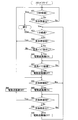
- movement of the vacuum cleaner of 1st Embodiment of this invention The flowchart which shows operation
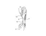
- FIG. 1 is a perspective view showing the vacuum cleaner of the first embodiment.
- the electric vacuum cleaner 1 includes a main body 4 that houses an electric blower 3 (see FIG. 6) and a dust collector (not shown).
- a suction port body 5 having an air inlet (not shown) facing the floor is rotatably connected to the lower portion of the main body portion 4, and the main body portion 4 can be tilted with respect to the suction port body 5.
- the vacuum cleaner 1 is comprised in the vertical type which arrange
- the operation unit 13 includes operation buttons such as a “strong” button, a “weak” button, a “stop” button, and a “standby” button.
- the “strong” button drives the electric blower 3 with a predetermined output (number of rotations).
- the “weak” button drives the electric blower 3 with a lower output (number of rotations) than when driven by the “strong” button.
- the “stop” button stops the electric blower 3.
- the “standby” button shifts to a standby mode to be described later.
- the operation unit 13 is provided with a plurality of keys (not shown) for performing various setting operations.
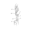
- a detachable extension pipe 6 extends in the vertical direction above the main body 4.
- a grip 8 that is gripped by the user is provided on the upper part of the extension pipe 6.
- a movable portion 9 is provided at one end of the extension pipe 6, and the movable portion 9 and the main body portion 4 are connected by a telescopic connection hose 7. Thereby, the extension pipe 6 and the electric blower 3 in the main body part 4 communicate with each other.
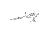
- the extension pipe 6 can be detached from the main body 4 by pressing the removal button 11.
- the holding part 8 can be hold
- the grip 8 can be detached from the extension pipe 6 by pressing the removal button 12.
- the holding part 8 can be hold
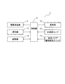
- FIG. 6 is a block diagram showing the configuration of the electric vacuum cleaner 1. Each part of the vacuum cleaner 1 is controlled by a control unit 2 provided in the main body 4.
- the electric blower 3, the operation unit 13, the storage unit 14, the display unit 15, the acceleration sensor 16, and the extension pipe attachment / detachment detection switch 17 are connected to the control unit 2.
- the storage unit 14 stores an operation program of the vacuum cleaner 1 and temporarily stores a calculation result by the control unit 2.
- the display unit 15 includes an LED or the like provided in the main body unit 4 and displays the operation state of the vacuum cleaner 1.
- the extension pipe attachment / detachment detection switch 17 detects the attachment / detachment state of the extension pipe 6.
- the acceleration sensor 16 is provided in the main body 4 and detects the posture of the main body 4 by detecting acceleration including gravitational acceleration. In the present embodiment, it is determined that the main body portion 4 is in the upright state when it is erected within 25 ° in the front-rear direction and the left-right direction with respect to the vertical. When the hand 4 is released and the main body 4 is tilted, it may be determined to be in an upright state.
- main body part 4 when the main body part 4 is inclined backward by 50 ° or more with respect to the vertical, it is determined that the main body part 4 is inclined by gripping the holding part 8. Further, when the main body part 4 is tilted 55 ° or more forward or in the left-right direction with respect to the vertical, it is determined that the main body part 4 is grounded by releasing the hand from the grip part 8.
- the main body 4 may be determined to be in the inclined state when it is in a predetermined angle range backward with respect to the vertical, and may be determined to be in the grounding state when the angle is larger than the inclined state.
- FIG. 7 is a flowchart showing the operation of the vacuum cleaner 1.
- an operation program is started, and it is determined in step # 11 whether the standby mode is set to default. If the standby mode is set to the default, the process proceeds to step # 20.
- step # 12 it is determined whether or not the “strong” button has been pressed. If the “strong” button has not been pressed, it is determined in step # 13 whether or not the “weak” button has been pressed.
- step # 14 If the “weak” button has not been pressed, it is determined in step # 14 whether or not the “stop” button has been pressed. If the “stop” button has not been pressed, it is determined in step # 15 whether or not the “standby” button has been pressed. If the “standby” button has not been pressed, the process returns to step # 12, and steps # 12 to # 15 are repeated until any operation button is pressed.
- step # 16 When the “strong” button is pressed, the electric blower 3 is driven at a high rotational speed in step # 16. Thereby, the suction port body 5 is moved by the holding part 8 and the floor surface is cleaned.
- the electric blower 3 When the “weak” button is pressed, the electric blower 3 is driven at a lower rotational speed than in step # 16 in step # 17. Thereby, the suction port body 5 is moved by the holding part 8 and the floor surface is cleaned. At this time, since the rotation speed of the electric blower 3 is low, cleaning can be performed with power saving.
- step # 18 When the “stop” button is pressed, the electric blower 3 is stopped in step # 18. Thereby, cleaning is completed.
- the electric blower 3 When the “strong” button or the “weak” button is pressed in a state where the extension pipe 6 is removed from the main body portion 4 or the gripping portion 8 is removed from the extension pipe 6, the electric blower 3 is driven. Thereby, a ceiling surface, a desk top, etc. are cleaned.
- step # 19 When the “standby” button is pressed, the electric blower 3 is stopped in step # 19. Then, in step # 20, a transition is made to the standby mode. In the standby mode, the electric blower 3 is driven and stopped based on the detection result of the acceleration sensor 16.
- FIG. 8 is a flowchart showing the operation in the standby mode.
- Steps # 31 and # 32 are in an upright standby state in which the main body 4 is on standby.
- step # 31 it is determined whether or not a predetermined time (here, 10 seconds) has elapsed since the transition to the upright standby state.
- a predetermined time here, 10 seconds
- step # 32 it is determined whether or not the main body 4 is upright by detection of the acceleration sensor 16. If the main body 4 is not upright, the process returns to step # 31, and steps # 31 and # 32 are repeated to wait for the upright state of the main body 4.
- step # 33 If the acceleration sensor 16 detects the upright state of the main body 4 from the upright standby state, the process proceeds to step # 33. At this time, when the upright state continues for a predetermined time (for example, 0.5 seconds), the process proceeds to step # 33 so that the upright state is not detected by an instantaneous operation contrary to the user's intention.
- a predetermined time for example, 0.5 seconds
- Steps # 33 to # 39 are in a stand-by state for waiting for the tilt of the main body 4.
- a predetermined time in this case, 1 minute
- the flow returns to the flowchart of FIG.
- step # 34 it is determined whether or not the main body 4 is grounded by the detection of the acceleration sensor 16. When the main body 4 is grounded, the process returns to step # 31 and shifts to an upright standby state. At this time, when the grounding state continues for a predetermined time (for example, 2 seconds), the process proceeds to step # 31 so that the grounding state is not detected by an instantaneous operation contrary to the user's intention.
- a predetermined time for example, 2 seconds
- step # 35 it is determined in step # 35 whether or not the extension pipe 6 has been removed by detection of the extension pipe attachment / detachment detection switch 17. If the extension pipe 6 has not been removed, the process proceeds to step # 39.
- the electric blower 3 is driven at step # 36. Thereby, a ceiling surface etc. can be cleaned, without operating the operation part 3.
- FIG. the rotation speed of the electric blower 3 may be set to a preset rotation speed, or may be the rotation speed when the previous electric blower 3 was driven.
- step # 37 the process waits until the extension pipe 6 is attached.
- the electric blower 3 is stopped at step # 38.
- step # 39 it is determined whether or not the main body 4 is tilted by the detection of the acceleration sensor 16. If the main body 4 is not tilted, the process returns to step # 33, and steps # 33 to # 39 are repeatedly performed to wait for the tilted state of the main body 4.
- the electric blower 3 is driven in step # 40. Accordingly, by moving the gripping portion 8 in the front-rear direction, the suction port body 5 integrated with the main body portion 4 moves back and forth, and cleaning of the floor surface is started. At this time, the rotation speed of the electric blower 3 may be set to a preset rotation speed, or may be the rotation speed when the previous electric blower 3 was driven.
- step # 41 it is determined whether or not the main body 4 is grounded by the detection of the acceleration sensor 16.
- the main-body part 4 is earth
- the process proceeds to step # 44 so that the grounding state is not detected by an instantaneous operation contrary to the user's intention. And it returns to step # 31 and transfers to an erect standby state.
- step # 42 it is determined whether or not the main body 4 is upright by detection of the acceleration sensor 16. If the main body 4 is not upright, the process returns to step # 41, and steps # 41 and # 42 are repeated.
- step # 43 When the upright state of the main body 4 is detected by the acceleration sensor 16, the process proceeds to step # 43 and the electric blower 3 is stopped. At this time, when the upright state continues for a predetermined time (for example, 1 second), the process proceeds to step # 43 so that the upright state is not detected by an instantaneous operation contrary to the user's intention. And it returns to step # 33 and transfers to a tilt standby state.
- a predetermined time for example, 1 second
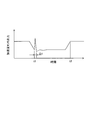
- FIG. 9 is a diagram showing the detection results by the acceleration sensor 16 in steps # 39 and # 42.
- the vertical axis represents the output in the front-rear direction of the acceleration sensor 16, and the horizontal axis represents time.
- the main body 4 is inclined in the front-rear direction, and the electric blower 6 is driven at time t1 in step # 40. Moreover, the main-body part 4 stands upright and the electric blower 6 is stopped by time # 2 by step # 43.
- acceleration is applied to the main body 4 when the electric blower 6 is driven, and the output of the acceleration sensor 16 detects an abnormal value. For this reason, immediately after the main body 4 is inclined and the electric blower 6 is driven, the output of the acceleration sensor 16 may change and it may be determined that the main body 4 is upright.
- the electric blower 6 when the electric blower 6 is driven, the electric blower 6 is prohibited from being stopped based on the detection result by the acceleration sensor 16 for a predetermined time ⁇ t (for example, 0.3 seconds). That is, during the period of time ⁇ t, the detection result of the acceleration sensor 16 is ignored or the detection of the acceleration sensor 16 is stopped. Thereby, stop of the electric blower 3 due to erroneous detection of the acceleration sensor 16 can be prevented.
- a predetermined time ⁇ t for example, 0.3 seconds
- the electric blower 3 is stopped when the main body portion 4 stands upright by detection of the acceleration sensor 16, and the electric blower 3 is driven when the main body portion 4 tilts in a predetermined direction from the upright state.
- the user does not need to perform an operation, and the convenience of the vacuum cleaner 1 can be improved.
- the electric blower 3 since the electric blower 3 is stopped when the main body 4 is grounded, the electric blower 3 can be stopped and power saving can be achieved by leaving the hand away from the gripping portion 8. Moreover, since the upright state, the inclined state, and the grounding state of the main body 4 are detected by the single acceleration sensor 16, it is not necessary to provide a large number of detection switches, and the number of parts is reduced, thereby reducing the cost of the vacuum cleaner 1. be able to.
- the electric blower 6 is driven regardless of the detection result of the acceleration sensor 16, so that the ceiling surface and the like are cleaned even when the main body 4 is upright. Can do. It should be noted that a switch for detecting the mounting state of the grip portion 8 is provided, and the electric blower 6 is driven regardless of the detection result of the acceleration sensor 16 when the grip portion 8 is removed from the extension pipe 6 mounted on the main body portion 4. Also good.
- the electric blower 3 is driven based on the detection result of the acceleration sensor 16. Therefore, when the electric blower 3 exits from the standby mode, the electric blower 3 based on the detection result of the acceleration sensor 16. Is not driven. Therefore, the user can select whether or not to drive the electric blower 3 according to the posture of the main body 4, and the convenience of the vacuum cleaner 1 can be further improved.
- the stop of the electric blower 3 based on the detection result of the acceleration sensor 16 is prohibited for a predetermined period ( ⁇ t) from the start of the driving of the electric blower 3, the stop of the electric blower 3 due to erroneous detection of the acceleration sensor 16 can be prevented. it can. Therefore, the convenience of the vacuum cleaner 1 can be further improved.
- the output of the electric blower 3 may be variable in the standby mode by a predetermined operation. At this time, it is preferable to prohibit the stop of the electric blower 3 based on the detection result of the acceleration sensor 16 for a predetermined period after changing the output of the electric blower 3. Thereby, when the output of the electric blower 3 changes, the electric blower 3 can be prevented from being stopped due to erroneous detection of the acceleration sensor 16.
- This embodiment is configured in the same manner as the electric vacuum cleaner 1 of the first embodiment shown in FIGS. 1 and 2, and the operation in the standby mode is different from that of the first embodiment. Further, when the extension pipe 6 is removed, the standby mode is exited. Other parts are the same as those in the first embodiment.
- the grip 8 is connected to the main body 4 via the extension pipe 6, and the main body 4 moves according to the movement of the grip 8. For this reason, the acceleration of the grip 8 can be detected by the acceleration sensor 16 provided in the main body 4. When the grip portion 8 moves suddenly, the acceleration detected by the acceleration sensor 16 becomes larger than that during normal cleaning.
- the output of the electric blower 3 is varied when the left-right acceleration detected by the acceleration sensor 16 exceeds the predetermined value by rapidly swinging the grip portion 8 to the left and right.
- FIG. 10 is a flowchart showing the operation in the standby mode of the vacuum cleaner 1 of the present embodiment.
- Steps # 51 and # 52 are in an upright standby state in which the main body 4 is on standby.
- step # 51 it is determined whether or not a predetermined time (here, 10 seconds) has elapsed since the transition to the upright standby state.
- a predetermined time here, 10 seconds
- step # 52 it is determined whether or not the main body 4 is upright by detection of the acceleration sensor 16. If the main body 4 is not upright, the process returns to step # 51, and steps # 51 and # 52 are repeatedly performed to wait for the upright state of the main body 4.
- step # 53 When the upright state of the main body 4 is detected by the acceleration sensor 16 from the upright standby state, the process proceeds to step # 53. At this time, when the upright state continues for a predetermined time (for example, 0.5 seconds), the process proceeds to step # 53 so that the upright state is not detected by an instantaneous operation contrary to the user's intention.
- a predetermined time for example, 0.5 seconds
- Steps # 53 to # 55 are in a stand-by state for waiting for the tilt of the main body 4.
- step # 53 it is determined whether or not a predetermined time (in this case, 1 minute) has elapsed since the transition to the tilt standby state.
- a predetermined time in this case, 1 minute
- step # 54 it is determined whether or not the main body 4 is grounded by the detection of the acceleration sensor 16. When the main body 4 is grounded, the process returns to step # 51 and shifts to an upright standby state. At this time, when the grounding state continues for a predetermined time (for example, 2 seconds), the process proceeds to step # 51 so that the grounding state is not detected by an instantaneous operation contrary to the user's intention.
- a predetermined time for example, 2 seconds
- step # 55 it is determined whether or not the main body 4 is tilted by the detection of the acceleration sensor 16. If the main body 4 is not tilted, the process returns to step # 53, and steps # 53 to # 55 are repeated to wait for the tilted state of the main body 4.
- the electric blower 3 is driven with an output when the “weak” button is pressed in step # 56. Accordingly, by moving the gripping portion 8 in the front-rear direction, the suction port body 5 integrated with the main body portion 4 moves back and forth, and cleaning of the floor surface is started.
- step # 57 it is determined whether or not the main body 4 is grounded by the detection of the acceleration sensor 16.
- the main-body part 4 is earth
- the process proceeds to step # 64 when the grounding state continues for a predetermined time (for example, 2 seconds) so that the grounding state is not detected by a momentary operation contrary to the user's intention. And it returns to step # 51 and transfers to an erect standby state.
- step # 58 it is determined in step # 58 whether the main unit 4 has swung in the left-right direction. If the acceleration in the left-right direction of the main body 4 detected by the acceleration sensor 16 exceeds a predetermined value, it is determined that the main body 4 has been swung due to the sudden swing of the grip 8 and the process proceeds to step # 59. If it is determined that the main body 4 is not swinging left and right, the process proceeds to step # 62.
- step # 59 the output of the electric blower 3 is increased, and the electric blower 3 is driven by the output when the “strong” button is pressed. Thereby, the user does not need to press the operation button of the operation unit 13 and can change the output of the electric blower 3 only by swinging the gripping unit 8.
- step # 60 after the output of the electric blower 3 is increased, the process waits until a predetermined time elapses.
- the electric blower 3 is driven with an output when the “weak” button is pressed.
- the output of the electric blower 3 is reduced in step # 61 when a predetermined time has elapsed in step # 60, but the output of the electric blower 3 is reduced when the gripping portion 8 is swung again in the left-right direction. May be. Further, the output of the electric blower 3 may be increased when the gripping portion 8 is swung in the left-right direction, and the output of the electric blower 3 may be decreased when the holding portion 8 is swung in the vertical direction. At this time, when the acceleration in the horizontal direction or the vertical direction of the main body 4 detected by the acceleration sensor 16 exceeds a predetermined value, it is determined that the main body 4 has been swung due to the sudden swing of the grip 8 and the electric blower 3 The output of is variable.
- the output of the electric blower 3 is increased when the hand holding the gripping portion 8 is rotated in one direction (for example, clockwise), and the output of the electric blower 3 is rotated in the other direction (for example, counterclockwise). May be reduced.
- the combined value of the acceleration in the left-right direction, the up-down direction, and the front-rear direction of the main body portion 4 detected by the acceleration sensor 16 exceeds a predetermined value, it is determined that the main body portion 4 has rotated due to the sudden rotation of the grip portion 8.
- the output of the electric blower 3 is varied.
- step # 62 it is determined whether or not the main body 4 is upright by detection of the acceleration sensor 16. If the main body 4 is not upright, the process returns to step # 57, and steps # 57 to # 62 are repeated.
- step # 63 When the upright state of the main body 4 is detected by the acceleration sensor 16, the process proceeds to step # 63 and the electric blower 3 is stopped. At this time, when the upright state continues for a predetermined time (for example, 1 second), the process proceeds to step # 63 so that the upright state is not detected by an instantaneous operation contrary to the user's intention. And it returns to step # 53 and transfers to a tilt standby state.
- a predetermined time for example, 1 second
- step # 56 when the electric blower 6 is driven in step # 56, the stop of the electric blower 6 based on the detection result by the acceleration sensor 16 is prohibited for a predetermined time ⁇ t (see FIG. 9). .
- steps # 59 and # 61 after the output of the electric blower 3 is changed, the stop of the electric blower 3 and the change of the output based on the detection result of the acceleration sensor 16 are prohibited for a predetermined period. Thereby, when the output of the electric blower 3 is changed, it is possible to prevent the electric blower 3 from being stopped due to erroneous detection of the acceleration sensor 16 and the continuous output from being changed.
- the output of the electric blower 3 is varied when the acceleration sensor 16 detects that the grip portion 8 has moved in a predetermined direction with an acceleration exceeding a predetermined value, there are many in the vicinity of the grip portion 8. It is not necessary to provide an operation button, and the output of the electric blower 3 can be easily changed. Moreover, even if a user's eyes are inconvenient, operation of an operation button is not required and the output of the electric blower 3 can be changed easily. Therefore, the convenience of the vacuum cleaner 1 can be improved.
- the output of the electric blower 3 is varied when the gripping portion 8 is swung in the left-right direction or the vertical direction, the output of the electric blower 3 can be varied with a simple operation.
- the output of the electric blower 3 is varied when the gripping portion 8 is rotated, the output of the electric blower 3 can be varied with a simple operation.
- the suction port body 5 is provided in the lower part of the main body part 4 so as to be freely rotatable and the gripping part 8 is a vertical electric vacuum cleaner 1 connected to the suction port body 5 via the main body part 4,
- the gripping part 8 is a vertical electric vacuum cleaner 1 connected to the suction port body 5 via the main body part 4
- the convenience of the vacuum cleaner 1 can be improved.
- the cleaning start and end Sometimes the user does not need to perform an operation, and the convenience of the vacuum cleaner 1 can be improved.
- the posture of the main body 4 is detected by the single acceleration sensor 16 and the movement of the grip 8 is detected, there is no need to provide a large number of detection switches, and the cost of the vacuum cleaner 1 can be reduced by reducing the number of parts. Can be reduced.
- the stop of the electric blower 3 and the change of the output based on the detection result of the acceleration sensor 16 are prohibited for a predetermined period after the output of the electric blower 3 is changed, the stop of the electric blower 3 due to the erroneous detection of the acceleration sensor 16 or Continuous output variation can be prevented. Therefore, the convenience of the vacuum cleaner 1 can be further improved.
- the electric blower 3 is driven based on the detection result of the acceleration sensor 16. Therefore, when the electric blower 3 exits from the standby mode, the electric blower 3 based on the detection result of the acceleration sensor 16. Is not driven. Therefore, the user can select whether or not to drive the electric blower 3 according to the posture of the main body 4, and the convenience of the vacuum cleaner 1 can be further improved.
- the vertical vacuum cleaner 1 in which the suction port body 5 is disposed below the main body portion 4 has been described, but the grip portion is connected to the main body portion 4 via a flexible connection hose. It may be a canister type vacuum cleaner to which 8 and the suction port body 5 are connected.
- the present invention can be used for a vacuum cleaner in which a user grips a grip portion and moves a suction port body.
Abstract
An electric vacuum cleaner (1) provided with a main body (4) that houses an electric fan (3), an intake port (5) connected rotatably below the main body (4), and a grip (8) that is disposed above the main body (4) and is grasped by the user, is provided with an acceleration sensor (16), which detects the position of the main body (4) and stops the electric fan (3) when the main body (4) is upright and runs the electric fan (3) when the main body is tilted from the upright state in a prescribed direction.
Description
把持部を把持して吸込口体を移動させる電気掃除機に関する。
It relates to a vacuum cleaner that grips the grip and moves the suction port.
従来の電気掃除機は特許文献1に開示されている。この電気掃除機は電動送風機を内装する本体部を備え、本体部の下方に吸込口体が本体部に対して回動自在に連結された縦型に構成される。吸込口体は床面に対向する吸気口が開口して床面に摺動する。本体部には着脱自在の延長パイプが上方に延びて配され、延長パイプの上端には使用者が把持する把持部が設けられる。また、本体部の上面には使用者の操作によって電動送風機のオンオフを行う操作部が設けられる。
A conventional vacuum cleaner is disclosed in Patent Document 1. This vacuum cleaner is provided with a main body part that houses an electric blower, and is configured in a vertical type in which a suction port body is rotatably connected to the main body part below the main body part. The suction port body slides on the floor surface with the intake port facing the floor surface opened. A detachable extension pipe extends upward in the main body, and a gripping part that a user grips is provided on the upper end of the extension pipe. In addition, an operation unit for turning on and off the electric blower by a user operation is provided on the upper surface of the main body.
操作部の操作によって電動送風機が駆動されると、把持部の操作によって吸込口体が本体部とともに移動して床面上を摺動する。これにより、床面の掃除が行われる。この時、本体部は直立した状態から吸込口体に対して回動して傾斜し、把持部を前後方向に移動操作することによって吸込口体が前後に移動する。掃除が終了すると操作部の操作によって電動送風機が停止され、本体部を立設して電気掃除機が収納される。
When the electric blower is driven by the operation of the operation unit, the suction port body moves together with the main body unit by the operation of the gripping unit and slides on the floor surface. Thereby, the floor surface is cleaned. At this time, the main body portion rotates and tilts with respect to the suction port body from an upright state, and the suction port body moves back and forth by operating the grip portion to move in the front-rear direction. When the cleaning is completed, the electric blower is stopped by the operation of the operation unit, the main body unit is erected and the electric vacuum cleaner is stored.
また、従来の他の電気掃除機は特許文献2に開示されている。この電気掃除機は電動送風機を内装する本体部に可撓性の接続ホースが接続されたキャニスター型に構成される。接続ホースの先端には使用者が把持する把持部が設けられるとともに延長パイプが連結される。延長パイプには床面に対向する吸気口を開口した吸込口体が連結される。
Further, another conventional vacuum cleaner is disclosed in Patent Document 2. This electric vacuum cleaner is configured in a canister type in which a flexible connecting hose is connected to a main body portion that houses an electric blower. A gripping part to be gripped by the user is provided at the tip of the connection hose and an extension pipe is connected. The extension pipe is connected to a suction port body having an intake port facing the floor surface.
把持部の近傍には電動送風機の運転状態を指示する操作部が設けられる。操作部は「切」ボタン、「強」ボタン、「中」ボタン、「弱」ボタン等の複数の操作ボタンを有している。「強」ボタンは電動送風機を所定の出力(回転数)で駆動する。「中」ボタンは電動送風機を「強」ボタンによる駆動時よりも低い出力で駆動する。「弱」ボタンは電動送風機を「中」ボタンによる駆動時よりも低い出力で駆動する。「切」ボタンは電動送風機を停止する。
An operation unit for instructing the operating state of the electric blower is provided in the vicinity of the grip unit. The operation unit has a plurality of operation buttons such as a “OFF” button, a “strong” button, a “middle” button, and a “weak” button. The “strong” button drives the electric blower at a predetermined output (number of rotations). The “middle” button drives the electric blower at a lower output than when driven by the “strong” button. The “weak” button drives the electric blower at a lower output than when driven by the “middle” button. The “OFF” button stops the electric blower.
操作部の「強」ボタン等を手指で押下すると操作ボタンに応じた出力で電動送風機が駆動される。そして、把持部を前後方向に移動操作することによって吸込口体が前後に移動して床面上を摺動して床面の掃除が行われる。掃除中に「強」ボタン、「中」ボタン、「弱」ボタンを押下すると、電動送風機の出力が可変される。これにより、被掃除面に応じて強力に塵埃を吸い込んで掃除を行う場合や、電力消費を抑制して弱い吸引力で掃除を行う場合等を使い分けることができる。掃除が終了すると操作部の「切」ボタンが押下され、電動送風機が停止する。
When the “strong” button on the operation unit is pressed with a finger, the electric blower is driven with an output corresponding to the operation button. Then, by moving the grip portion in the front-rear direction, the suction port body moves back and forth and slides on the floor surface to clean the floor surface. When the “strong” button, “medium” button, and “weak” button are pressed during cleaning, the output of the electric blower is varied. Thereby, it is possible to properly use the case where the dust is strongly sucked in accordance with the surface to be cleaned and the case where the cleaning is performed with a weak suction force while suppressing the power consumption. When cleaning is completed, the “OFF” button on the operation unit is pressed, and the electric blower stops.
しかしながら、特許文献1の電気掃除機によると、操作部が本体部に設けられるため、掃除の開始時及び終了時に使用者は手元から離れた操作部を操作する必要がある。このため、電気掃除機の利便性が悪い問題があった。
However, according to the electric vacuum cleaner of Patent Document 1, since the operation unit is provided in the main body, the user needs to operate the operation unit away from the hand at the start and end of cleaning. For this reason, there existed a problem that the convenience of a vacuum cleaner was bad.
使用者の手元で操作できるように操作部を把持部に設けると構造が複雑になるため電気掃除機が大型化する。縦型の電気掃除機は本体部と一体に吸込口体を移動させるため小型軽量化する必要があり、大型化されると利便性が低下する問題がある。
¡If the operation part is provided in the grip part so that it can be operated by the user, the structure becomes complicated and the vacuum cleaner becomes larger. The vertical vacuum cleaner needs to be reduced in size and weight in order to move the suction port body integrally with the main body, and there is a problem that convenience is reduced when the size is increased.
また、特許文献2の電気掃除機によると、操作部が複数の操作ボタンを有するため、把持部を把持しながら全ての操作ボタンに手指が届かない場合がある。このため、電動送風機の出力を可変する際に把持部の把持位置を持ち替えて所望の操作ボタンを押下する必要がある。従って、電気掃除機の利便性が悪い問題があった。
In addition, according to the electric vacuum cleaner of Patent Document 2, since the operation unit has a plurality of operation buttons, fingers may not reach all the operation buttons while holding the holding unit. For this reason, when changing the output of the electric blower, it is necessary to change the holding position of the holding portion and press a desired operation button. Therefore, there is a problem that the convenience of the vacuum cleaner is poor.
加えて、使用者の目が不自由な場合に複数の操作ボタンを区別して押下することが困難であり、電気掃除機の利便性が悪い問題もあった。
In addition, it is difficult to distinguish and press a plurality of operation buttons when the user is blind, and there is a problem that the convenience of the vacuum cleaner is poor.
本発明は、利便性を向上できる電気掃除機を提供することを目的とする。
This invention aims at providing the vacuum cleaner which can improve the convenience.
上記目的を達成するために本発明は、電動送風機を内装する本体部と、前記本体部の下方に回動自在に連結される吸込口体と、前記本体部の上方に配されて使用者が把持する把持部とを備えた電気掃除機において、前記本体部の姿勢を検知する加速度センサを設け、前記加速度センサの検知結果に基づいて、前記本体部が直立した際に前記電動送風機を停止するとともに、前記本体部が直立状態から所定方向に傾斜した際に前記電動送風機を駆動したことを特徴としている。
In order to achieve the above-mentioned object, the present invention provides a main body part that houses an electric blower, a suction port body that is rotatably connected to the lower part of the main body part, and a user who is disposed above the main body part. In an electric vacuum cleaner comprising a gripping part for gripping, an acceleration sensor for detecting a posture of the main body part is provided, and the electric blower is stopped when the main body part stands upright based on a detection result of the acceleration sensor In addition, the electric blower is driven when the main body portion is inclined in a predetermined direction from the upright state.
この構成によると、電動送風機を内装する本体部を直立した状態から把持部を把持して所定方向に傾斜させると、加速度センサの検知によって電動送風機が駆動される。これにより、本体部と一体の吸込口体を把持部の操作によって移動させて床面の掃除が行われる。把持部の移動によって本体部を立設すると、加速度センサの検知によって電動送風機が停止される。
According to this configuration, when the gripping portion is gripped and tilted in a predetermined direction from the upright state of the main body that houses the electric blower, the electric blower is driven by the detection of the acceleration sensor. As a result, the floor surface is cleaned by moving the suction port that is integral with the main body by operating the grip. When the main body portion is erected by the movement of the grip portion, the electric blower is stopped by detection of the acceleration sensor.
また本発明は、上記構成の電気掃除機において、前記本体部が接地した際に前記電動送風機を停止したことを特徴としている。この構成によると、使用者が把持部から手を離して本体部が床面に接地されると、電動送風機が停止される。
Further, according to the present invention, in the electric vacuum cleaner having the above-described configuration, the electric blower is stopped when the main body is grounded. According to this configuration, when the user removes his / her hand from the grip portion and the main body portion is grounded to the floor surface, the electric blower is stopped.
また本発明は、上記構成の電気掃除機において、前記電動送風機に連通して前記本体部に対して着脱自在の延長パイプと一体に前記把持部が形成され、直立した前記本体部から前記延長パイプを取り外した際に前記加速度センサの検知結果に拘わらず前記電動送風機を駆動したことを特徴としている。この構成によると、把持部を把持して延長パイプを直立した本体部から取り外すと電動送風機が駆動され、天井等の掃除が行われる。
According to the present invention, in the vacuum cleaner configured as described above, the grip portion is formed integrally with an extension pipe that communicates with the electric blower and is detachable from the body portion, and the extension pipe extends from the upright body portion. When the motor is removed, the electric blower is driven regardless of the detection result of the acceleration sensor. According to this configuration, when the gripping part is gripped and the extension pipe is removed from the upright main body part, the electric blower is driven to clean the ceiling and the like.
また本発明は、上記構成の電気掃除機において、前前記加速度センサの検知結果に基づいて前記電動送風機の駆動及び停止を行うスタンバイモードを設け、前記本体部に設けた操作部の操作によって前記スタンバイモードに移行することを特徴としている。この構成によると、操作部の操作によってスタンバイモードに移行すると、加速度センサで検知した本体部の姿勢によって電動送風機がオンオフされる。スタンバイモードから抜け出ると、加速度センサの検知結果に基づいた電動送風機の駆動が行われない。
According to the present invention, in the vacuum cleaner configured as described above, a standby mode for driving and stopping the electric blower based on a detection result of the acceleration sensor is provided, and the standby is performed by operating an operation unit provided in the main body. It is characterized by shifting to the mode. According to this configuration, when shifting to the standby mode by operating the operation unit, the electric blower is turned on / off depending on the posture of the main body detected by the acceleration sensor. When exiting the standby mode, the electric blower is not driven based on the detection result of the acceleration sensor.
また本発明は、上記構成の電気掃除機において、前記電動送風機の駆動開始から所定期間は前記加速度センサの検知結果に基づく前記電動送風機の停止を禁止したことを特徴としている。
Further, the present invention is characterized in that, in the vacuum cleaner having the above configuration, the electric blower is prohibited from being stopped based on a detection result of the acceleration sensor for a predetermined period from the start of driving of the electric blower.
また本発明は、上記構成の電気掃除機において、前記電動送風機の出力を可変してから所定期間は前記加速度センサの検知結果に基づく前記電動送風機の停止を禁止したことを特徴としている。
Further, the present invention is characterized in that, in the electric vacuum cleaner having the above-described configuration, the electric blower is prohibited from being stopped based on the detection result of the acceleration sensor for a predetermined period after the output of the electric blower is varied.
また本発明は、床面に面した吸気口を開口する吸込口体と、前記吸込口体に連結されるとともに使用者により把持して前記吸込口体を移動させる把持部と、電動送風機を内装する本体部と、前記把持部の加速度を検知する加速度センサとを備え、前記把持部が所定方向に所定値を超える加速度で移動したことを前記加速度センサにより検知した際に、前記電動送風機の出力を可変したことを特徴としている。
The present invention also includes a suction port body that opens a suction port facing the floor, a gripping part that is connected to the suction port body and that is gripped by a user and moves the suction port body, and an electric blower. An output of the electric blower when the acceleration sensor detects that the gripper has moved in a predetermined direction at an acceleration exceeding a predetermined value. It is characterized by having changed.
この構成によると、電動送風機を駆動して使用者により把持された把持部を前後方向に移動操作すると吸込口体が前後に移動して床面の掃除が行われる。掃除中に把持部を所定方向に急激に移動させると、把持部の加速度が所定値を超えて加速度センサによって検知される。これにより、回転数を増減して電動送風機の出力が可変される。
According to this configuration, when the electric blower is driven and the gripping part gripped by the user is moved in the front-rear direction, the suction port body moves back and forth and the floor surface is cleaned. When the grip portion is suddenly moved in a predetermined direction during cleaning, the acceleration of the grip portion exceeds a predetermined value and is detected by the acceleration sensor. Thereby, the number of rotations is increased or decreased to vary the output of the electric blower.
また本発明は、上記構成の電気掃除機において、前記把持部を左右方向または上下方向に揺動した際に前記電動送風機の出力を可変したことを特徴としている。この構成によると、把持部を左右方向や上下方向に急激に揺動させると、電動送風機を出力が可変される。
Further, the present invention is characterized in that, in the vacuum cleaner having the above-described configuration, the output of the electric blower is varied when the gripping portion is swung in the left-right direction or the up-down direction. According to this configuration, the output of the electric blower is varied when the gripping portion is swung suddenly in the left-right direction or the up-down direction.
また本発明は、上記構成の電気掃除機において、前記把持部を回転させた際に前記電動送風機を出力を可変したことを特徴としている。この構成によると、把持部を把持した手を円が描かれるように回転させると電動送風機を出力が可変される。
Further, the present invention is characterized in that, in the electric vacuum cleaner having the above-described configuration, the output of the electric blower is varied when the grip portion is rotated. According to this configuration, the output of the electric blower is varied when the hand holding the gripping portion is rotated so as to draw a circle.
また本発明は、上記構成の電気掃除機において、前記吸込口体が前記本体部の下方に回動自在に設けられ、前記把持部が前記本体部を介して前記吸込口体に連結されることを特徴としている。この構成によると、把持部を把持して本体部と一体に吸込口体が移動して掃除が行われる。
In the vacuum cleaner having the above-described configuration, the suction port body may be rotatably provided below the main body portion, and the grip portion may be connected to the suction port body via the main body portion. It is characterized by. According to this configuration, the gripping portion is gripped, and the suction port body moves integrally with the main body portion to perform cleaning.
また本発明は、上記構成の電気掃除機において、前記加速度センサを前記本体部に設けて前記本体部の姿勢を前記加速度センサにより検知し、前記本体部が直立した際に前記電動送風機を停止するとともに、前記本体部が直立状態から所定方向に傾斜した際に前記電動送風機を駆動したことを特徴としている。
According to the present invention, in the vacuum cleaner having the above-described configuration, the acceleration sensor is provided in the main body, the posture of the main body is detected by the acceleration sensor, and the electric blower is stopped when the main body is upright. In addition, the electric blower is driven when the main body portion is inclined in a predetermined direction from the upright state.
この構成によると、電動送風機を内装する本体部を直立した状態から把持部を把持して所定方向に傾斜させると、加速度センサの検知によって電動送風機が駆動される。これにより、本体部と一体の吸込口体を把持部の操作によって移動させて床面の掃除が行われる。把持部の移動によって本体部を立設すると、加速度センサの検知によって電動送風機が停止される。
According to this configuration, when the gripping portion is gripped and tilted in a predetermined direction from the upright state of the main body that houses the electric blower, the electric blower is driven by the detection of the acceleration sensor. As a result, the floor surface is cleaned by moving the suction port that is integral with the main body by operating the grip. When the main body portion is erected by the movement of the grip portion, the electric blower is stopped by detection of the acceleration sensor.
また本発明は、上記構成の電気掃除機において、前記電動送風機の出力を可変してから所定期間は前記加速度センサの検知結果に基づく前記電動送風機の出力可変を禁止したことを特徴としている。
Further, the present invention is characterized in that, in the electric vacuum cleaner having the above configuration, the output of the electric blower is prohibited from being changed based on the detection result of the acceleration sensor for a predetermined period after the output of the electric blower is changed.
本発明によると、加速度センサの検知によって本体部が直立した際に電動送風機を停止し、本体部が直立状態から所定方向に傾斜した際に電動送風機を駆動したので、掃除の開始及び終了時に使用者は操作を行う必要がなく電気掃除機の利便性を向上することができる。
According to the present invention, the electric blower is stopped when the main body portion stands upright by detection of the acceleration sensor, and the electric blower is driven when the main body portion tilts in a predetermined direction from the upright state. The user does not need to perform an operation and can improve the convenience of the vacuum cleaner.
また本発明によると、把持部が所定方向に所定値を超える加速度で移動したことを加速度センサにより検知した際に、電動送風機の出力を可変したので、把持部の近傍に多数の操作ボタンを設ける必要がなく、容易に電動送風機の出力を変えることができる。また、使用者が目が不自由であっても操作ボタンの操作を必要とせず容易に電動送風機の出力を変えることができる。従って、電気掃除機の利便性を向上することができる。
Further, according to the present invention, when the acceleration sensor detects that the gripping part has moved in a predetermined direction with an acceleration exceeding a predetermined value, the output of the electric blower is changed, so that a large number of operation buttons are provided in the vicinity of the gripping part. There is no need, and the output of the electric blower can be easily changed. In addition, even if the user is blind, it is possible to easily change the output of the electric blower without requiring operation of the operation buttons. Therefore, the convenience of the vacuum cleaner can be improved.
以下に本発明の実施形態を図面を参照して説明する。図1は第1実施形態の電気掃除機を示す斜視図である。電気掃除機1は電動送風機3(図6参照)及び集塵部(不図示)を内装する本体部4を備えている。本体部4の下方には床面に面した吸気口(不図示)を有する吸込口体5が回動自在に連結され、本体部4は吸込口体5に対して傾倒可能になっている。これにより、電気掃除機1は本体部4の下方に吸込口体5を配して一体に移動する縦型に構成される。
Embodiments of the present invention will be described below with reference to the drawings. FIG. 1 is a perspective view showing the vacuum cleaner of the first embodiment. The electric vacuum cleaner 1 includes a main body 4 that houses an electric blower 3 (see FIG. 6) and a dust collector (not shown). A suction port body 5 having an air inlet (not shown) facing the floor is rotatably connected to the lower portion of the main body portion 4, and the main body portion 4 can be tilted with respect to the suction port body 5. Thereby, the vacuum cleaner 1 is comprised in the vertical type which arrange | positions the suction inlet body 5 under the main-body part 4, and moves integrally.
本体部4の上面には操作部13が設けられる。操作部13は「強」ボタン、「弱」ボタン、「停止」ボタン、「スタンバイ」ボタン等の操作ボタンを有する。「強」ボタンは電動送風機3を所定の出力(回転数)で駆動する。「弱」ボタンは電動送風機3を「強」ボタンによる駆動時よりも低い出力(回転数)で駆動する。「停止」ボタンは電動送風機3を停止する。「スタンバイ」ボタンは後述するスタンバイモードに移行させる。また、操作部13には各種設定操作を行う複数のキー(不図示)が設けられる。
An operation unit 13 is provided on the upper surface of the main body unit 4. The operation unit 13 includes operation buttons such as a “strong” button, a “weak” button, a “stop” button, and a “standby” button. The “strong” button drives the electric blower 3 with a predetermined output (number of rotations). The “weak” button drives the electric blower 3 with a lower output (number of rotations) than when driven by the “strong” button. The “stop” button stops the electric blower 3. The “standby” button shifts to a standby mode to be described later. The operation unit 13 is provided with a plurality of keys (not shown) for performing various setting operations.
本体部4の上方には着脱自在の延長パイプ6が鉛直方向に延びて配される。延長パイプ6の上部には使用者が把持する把持部8が設けられる。延長パイプ6の一端には可動部9が設けられ、可動部9と本体部4との間は伸縮自在の接続ホース7で連結される。これにより、延長パイプ6と本体部4内の電動送風機3とが連通する。
A detachable extension pipe 6 extends in the vertical direction above the main body 4. A grip 8 that is gripped by the user is provided on the upper part of the extension pipe 6. A movable portion 9 is provided at one end of the extension pipe 6, and the movable portion 9 and the main body portion 4 are connected by a telescopic connection hose 7. Thereby, the extension pipe 6 and the electric blower 3 in the main body part 4 communicate with each other.
図2に示すように、延長パイプ6は取外しボタン11の押圧によって本体部4から取り外すことができる。これにより、図3に示すように把持部8を把持して延長パイプ6により天井面の掃除や壁面に取付けた空気調和機の掃除等を行うことができる。また、図4に示すように、把持部8は取外しボタン12の押圧によって延長パイプ6から取り外すことができる。これにより、図5に示すように把持部8を把持して机上等の掃除を行うことができる。
As shown in FIG. 2, the extension pipe 6 can be detached from the main body 4 by pressing the removal button 11. Thereby, as shown in FIG. 3, the holding part 8 can be hold | gripped and the extension pipe 6 can clean a ceiling surface, the air conditioner attached to the wall surface, etc. can be performed. Further, as shown in FIG. 4, the grip 8 can be detached from the extension pipe 6 by pressing the removal button 12. Thereby, as shown in FIG. 5, the holding part 8 can be hold | gripped and a desk top etc. can be cleaned.
図6は電気掃除機1の構成を示すブロック図である。電気掃除機1は本体部4内に設けられた制御部2により各部が制御される。制御部2には電動送風機3、操作部13、記憶部14、表示部15、加速度センサ16、延長パイプ着脱検知スイッチ17が接続される。
FIG. 6 is a block diagram showing the configuration of the electric vacuum cleaner 1. Each part of the vacuum cleaner 1 is controlled by a control unit 2 provided in the main body 4. The electric blower 3, the operation unit 13, the storage unit 14, the display unit 15, the acceleration sensor 16, and the extension pipe attachment / detachment detection switch 17 are connected to the control unit 2.
記憶部14は電気掃除機1の動作プログラムを格納するとともに制御部2による演算結果を一時記憶する。表示部15は本体部4に設けられたLED等から成り、電気掃除機1の動作状態を表示する。延長パイプ着脱検知スイッチ17は延長パイプ6の着脱状態を検知する。
The storage unit 14 stores an operation program of the vacuum cleaner 1 and temporarily stores a calculation result by the control unit 2. The display unit 15 includes an LED or the like provided in the main body unit 4 and displays the operation state of the vacuum cleaner 1. The extension pipe attachment / detachment detection switch 17 detects the attachment / detachment state of the extension pipe 6.
加速度センサ16は本体部4に設けられ、重力加速度を含む加速度を検出して本体部4の姿勢を検知する。本実施形態では、本体部4が鉛直に対して前後方向及び左右方向に25゜以内で立設した際に直立状態と判定している。把持部8から手を離して本体部4が傾斜しても倒れない状態になったときを直立状態と判定してもよい。
The acceleration sensor 16 is provided in the main body 4 and detects the posture of the main body 4 by detecting acceleration including gravitational acceleration. In the present embodiment, it is determined that the main body portion 4 is in the upright state when it is erected within 25 ° in the front-rear direction and the left-right direction with respect to the vertical. When the hand 4 is released and the main body 4 is tilted, it may be determined to be in an upright state.
また、本体部4が鉛直に対して後方に50゜以上傾斜した場合に把持部8を把持して本体部4が傾斜された傾斜状態と判定している。また、本体部4が鉛直に対して前方または左右方向に55゜以上倒れた場合に、把持部8から手を離して本体部4が接地された接地状態と判定している。尚、本体部4が鉛直に対して後方に所定の角度範囲の時に傾斜状態と判定し、傾斜状態よりも大きい角度になったときに接地状態と判定してもよい。
Further, when the main body part 4 is inclined backward by 50 ° or more with respect to the vertical, it is determined that the main body part 4 is inclined by gripping the holding part 8. Further, when the main body part 4 is tilted 55 ° or more forward or in the left-right direction with respect to the vertical, it is determined that the main body part 4 is grounded by releasing the hand from the grip part 8. The main body 4 may be determined to be in the inclined state when it is in a predetermined angle range backward with respect to the vertical, and may be determined to be in the grounding state when the angle is larger than the inclined state.
図7は電気掃除機1の動作を示すフローチャートである。電気掃除機1が商用電源に接続されると動作プログラムが開始され、ステップ#11でスタンバイモードがデフォルトに設定されているか否かが判断される。スタンバイモードがデフォルトに設定されている場合はステップ#20に移行する。
FIG. 7 is a flowchart showing the operation of the vacuum cleaner 1. When the vacuum cleaner 1 is connected to a commercial power source, an operation program is started, and it is determined in step # 11 whether the standby mode is set to default. If the standby mode is set to the default, the process proceeds to step # 20.
スタンバイモードがデフォルトに設定されていない場合は通常モードが開始され、ステップ#12に移行する。ステップ#12では「強」ボタンが押下されたか否かが判断される。「強」ボタンが押下されていない場合はステップ#13で「弱」ボタンが押下されたか否かが判断される。
If the standby mode is not set to the default, the normal mode is started and the process proceeds to step # 12. In step # 12, it is determined whether or not the “strong” button has been pressed. If the “strong” button has not been pressed, it is determined in step # 13 whether or not the “weak” button has been pressed.
「弱」ボタンが押下されていない場合はステップ#14で「停止」ボタンが押下されたか否かが判断される。「停止」ボタンが押下されていない場合はステップ#15で「スタンバイ」ボタンが押下されたか否かが判断される。「スタンバイ」ボタンが押下されていない場合はステップ#12に戻り、いずれかの操作ボタンが押下されるまでステップ#12~#15が繰り返される。
If the “weak” button has not been pressed, it is determined in step # 14 whether or not the “stop” button has been pressed. If the “stop” button has not been pressed, it is determined in step # 15 whether or not the “standby” button has been pressed. If the “standby” button has not been pressed, the process returns to step # 12, and steps # 12 to # 15 are repeated until any operation button is pressed.
「強」ボタンが押下されると、ステップ#16で電動送風機3が高い回転数で駆動される。これにより、把持部8により吸込口体5を移動させて床面の掃除が行われる。「弱」ボタンが押下されると、ステップ#17で電動送風機3がステップ#16よりも低い回転数で駆動される。これにより、把持部8により吸込口体5を移動させて床面の掃除が行われる。この時、電動送風機3の回転数が低いため、省電力で掃除を行うことができる。
When the “strong” button is pressed, the electric blower 3 is driven at a high rotational speed in step # 16. Thereby, the suction port body 5 is moved by the holding part 8 and the floor surface is cleaned. When the “weak” button is pressed, the electric blower 3 is driven at a lower rotational speed than in step # 16 in step # 17. Thereby, the suction port body 5 is moved by the holding part 8 and the floor surface is cleaned. At this time, since the rotation speed of the electric blower 3 is low, cleaning can be performed with power saving.
「停止」ボタンが押下されると、ステップ#18で電動送風機3が停止される。これにより、掃除が終了する。尚、延長パイプ6を本体部4から取り外した状態や把持部8を延長パイプ6から取り外した状態で「強」ボタンまたは「弱」ボタンを押下すると、電動送風機3が駆動される。これにより、天井面や机上等の掃除が行われる。
When the “stop” button is pressed, the electric blower 3 is stopped in step # 18. Thereby, cleaning is completed. When the “strong” button or the “weak” button is pressed in a state where the extension pipe 6 is removed from the main body portion 4 or the gripping portion 8 is removed from the extension pipe 6, the electric blower 3 is driven. Thereby, a ceiling surface, a desk top, etc. are cleaned.
「スタンバイ」ボタンが押下されると、ステップ#19で電動送風機3が停止される。そして、ステップ#20でスタンバイモードに移行する。スタンバイモードは加速度センサ16の検知結果に基づいて電動送風機3の駆動及び停止を行う。
When the “standby” button is pressed, the electric blower 3 is stopped in step # 19. Then, in step # 20, a transition is made to the standby mode. In the standby mode, the electric blower 3 is driven and stopped based on the detection result of the acceleration sensor 16.
図8はスタンバイモードの動作を示すフローチャートである。ステップ#31、#32は本体部4の直立を待機する直立待機状態になっている。ステップ#31は直立待機状態に移行してから所定時間(ここでは、10秒)が経過したか否かが判断される。直立待機状態に移行してから所定時間が経過した場合は図7のフローチャートに戻る。
FIG. 8 is a flowchart showing the operation in the standby mode. Steps # 31 and # 32 are in an upright standby state in which the main body 4 is on standby. In step # 31, it is determined whether or not a predetermined time (here, 10 seconds) has elapsed since the transition to the upright standby state. When a predetermined time has elapsed since the transition to the upright standby state, the flow returns to the flowchart of FIG.
直立待機状態に移行してから所定時間が経過していない場合はステップ#32に移行する。ステップ#32では加速度センサ16の検知によって本体部4が直立したか否かが判断される。本体部4が直立していない場合はステップ#31に戻り、ステップ#31、#32が繰り返し行われて本体部4の直立状態を待機する。
If the predetermined time has not elapsed since the transition to the upright standby state, the process proceeds to step # 32. In step # 32, it is determined whether or not the main body 4 is upright by detection of the acceleration sensor 16. If the main body 4 is not upright, the process returns to step # 31, and steps # 31 and # 32 are repeated to wait for the upright state of the main body 4.
直立待機状態から本体部4の直立状態を加速度センサ16により検知すると、ステップ#33に移行する。この時、使用者の意図に反した一瞬の動作によって直立状態が検知されないように、直立状態が所定時間(例えば、0.5秒)継続したときにステップ#33に移行させている。
If the acceleration sensor 16 detects the upright state of the main body 4 from the upright standby state, the process proceeds to step # 33. At this time, when the upright state continues for a predetermined time (for example, 0.5 seconds), the process proceeds to step # 33 so that the upright state is not detected by an instantaneous operation contrary to the user's intention.
ステップ#33~#39は本体部4の傾斜を待機する傾斜待機状態になっている。ステップ#33では傾斜待機状態に移行してから所定時間(ここでは、1分)が経過したか否かが判断される。傾斜待機状態に移行してから所定時間が経過した場合は図7のフローチャートに戻る。
Steps # 33 to # 39 are in a stand-by state for waiting for the tilt of the main body 4. In step # 33, it is determined whether or not a predetermined time (in this case, 1 minute) has elapsed since the transition to the tilt standby state. When a predetermined time has elapsed since the transition to the tilt standby state, the flow returns to the flowchart of FIG.
傾斜待機状態に移行してから所定時間が経過していない場合はステップ#34に移行する。ステップ#34では加速度センサ16の検知によって本体部4が接地されたか否かが判断される。本体部4が接地された場合はステップ#31に戻り、直立待機状態に移行する。この時、使用者の意図に反した一瞬の動作によって接地状態が検知されないように、接地状態が所定時間(例えば、2秒)継続したときにステップ#31に移行させている。
If the predetermined time has not elapsed since the transition to the tilt standby state, the process proceeds to step # 34. In step # 34, it is determined whether or not the main body 4 is grounded by the detection of the acceleration sensor 16. When the main body 4 is grounded, the process returns to step # 31 and shifts to an upright standby state. At this time, when the grounding state continues for a predetermined time (for example, 2 seconds), the process proceeds to step # 31 so that the grounding state is not detected by an instantaneous operation contrary to the user's intention.
本体部4が接地されていない場合はステップ#35で延長パイプ着脱検知スイッチ17の検知によって延長パイプ6が取り外されたか否かが判断される。延長パイプ6が取り外されていない場合はステップ#39に移行する。延長パイプ6が取り外された場合はステップ#36で電動送風機3が駆動される。これにより、操作部3の操作を行わずに天井面等を掃除することができる。この時、電動送風機3の回転数は予め設定した回転数にしてもよく、前回電動送風機3を駆動したときの回転数にしてもよい。
If the main body 4 is not grounded, it is determined in step # 35 whether or not the extension pipe 6 has been removed by detection of the extension pipe attachment / detachment detection switch 17. If the extension pipe 6 has not been removed, the process proceeds to step # 39. When the extension pipe 6 is removed, the electric blower 3 is driven at step # 36. Thereby, a ceiling surface etc. can be cleaned, without operating the operation part 3. FIG. At this time, the rotation speed of the electric blower 3 may be set to a preset rotation speed, or may be the rotation speed when the previous electric blower 3 was driven.
ステップ#37では延長パイプ6が装着されるまで待機する。延長パイプ6が装着されると、ステップ#38で電動送風機3が停止される。
In step # 37, the process waits until the extension pipe 6 is attached. When the extension pipe 6 is attached, the electric blower 3 is stopped at step # 38.
ステップ#39では加速度センサ16の検知によって本体部4が傾斜したか否かが判断される。本体部4が傾斜していない場合はステップ#33に戻り、ステップ#33~#39が繰り返し行われて本体部4の傾斜状態を待機する。
In step # 39, it is determined whether or not the main body 4 is tilted by the detection of the acceleration sensor 16. If the main body 4 is not tilted, the process returns to step # 33, and steps # 33 to # 39 are repeatedly performed to wait for the tilted state of the main body 4.
把持部8を把持して本体部4が後方に傾斜した傾斜状態になると、ステップ#40で電動送風機3が駆動される。これにより、把持部8を前後方向に移動操作することによって本体部4と一体の吸込口体5が前後に移動して床面の掃除が開始される。この時、電動送風機3の回転数は予め設定した回転数にしてもよく、前回電動送風機3を駆動したときの回転数にしてもよい。
When the grip portion 8 is gripped and the main body portion 4 is tilted backward, the electric blower 3 is driven in step # 40. Accordingly, by moving the gripping portion 8 in the front-rear direction, the suction port body 5 integrated with the main body portion 4 moves back and forth, and cleaning of the floor surface is started. At this time, the rotation speed of the electric blower 3 may be set to a preset rotation speed, or may be the rotation speed when the previous electric blower 3 was driven.
ステップ#41では加速度センサ16の検知によって本体部4が接地されたか否かが判断される。本体部4が接地された場合はステップ#44に移行して電動送風機3が停止される。この時、使用者の意図に反した一瞬の動作によって接地状態が検知されないように、接地状態が所定時間(例えば、2秒)継続したときにステップ#44に移行させている。そして、ステップ#31に戻り、直立待機状態に移行する。
In step # 41, it is determined whether or not the main body 4 is grounded by the detection of the acceleration sensor 16. When the main-body part 4 is earth | grounded, it transfers to step # 44 and the electric blower 3 is stopped. At this time, when the grounding state continues for a predetermined time (for example, 2 seconds), the process proceeds to step # 44 so that the grounding state is not detected by an instantaneous operation contrary to the user's intention. And it returns to step # 31 and transfers to an erect standby state.
ステップ#42では加速度センサ16の検知によって本体部4が直立したか否かが判断される。本体部4が直立していない場合はステップ#41に戻り、ステップ#41、#42が繰り返し行われる。
In step # 42, it is determined whether or not the main body 4 is upright by detection of the acceleration sensor 16. If the main body 4 is not upright, the process returns to step # 41, and steps # 41 and # 42 are repeated.
本体部4の直立状態を加速度センサ16により検知すると、ステップ#43に移行して電動送風機3が停止される。この時、使用者の意図に反した一瞬の動作によって直立状態が検知されないように、直立状態が所定時間(例えば、1秒)継続したときにステップ#43に移行させている。そして、ステップ#33に戻り、傾斜待機状態に移行する。
When the upright state of the main body 4 is detected by the acceleration sensor 16, the process proceeds to step # 43 and the electric blower 3 is stopped. At this time, when the upright state continues for a predetermined time (for example, 1 second), the process proceeds to step # 43 so that the upright state is not detected by an instantaneous operation contrary to the user's intention. And it returns to step # 33 and transfers to a tilt standby state.
尚、スタンバイモード時に操作部13の操作ボタンが操作されるとスタンバイモードを抜け出て通常モードに移行する。これにより、操作ボタンの押下によって電動送風機3の駆動及び停止が行われる。
When the operation button on the operation unit 13 is operated in the standby mode, the standby mode is exited and the normal mode is entered. Thereby, the electric blower 3 is driven and stopped by pressing the operation button.
図9はステップ#39、#42の加速度センサ16による検知結果を示す図である。縦軸は加速度センサ16の前後方向の出力を示し、横軸は時間を示している。前後方向に本体部4が傾斜してステップ#40により時刻t1で電動送風機6が駆動される。また、本体部4が直立してステップ#43により時刻t2で電動送風機6が停止されている。
FIG. 9 is a diagram showing the detection results by the acceleration sensor 16 in steps # 39 and # 42. The vertical axis represents the output in the front-rear direction of the acceleration sensor 16, and the horizontal axis represents time. The main body 4 is inclined in the front-rear direction, and the electric blower 6 is driven at time t1 in step # 40. Moreover, the main-body part 4 stands upright and the electric blower 6 is stopped by time # 2 by step # 43.
同図によると、電動送風機6の駆動時に本体部4に加速度が加わり、加速度センサ16の出力が異常値を検出する。このため、本体部4が傾斜して電動送風機6を駆動した直後に加速度センサ16の出力が変化して本体部4が直立したと判断される虞がある。
According to the figure, acceleration is applied to the main body 4 when the electric blower 6 is driven, and the output of the acceleration sensor 16 detects an abnormal value. For this reason, immediately after the main body 4 is inclined and the electric blower 6 is driven, the output of the acceleration sensor 16 may change and it may be determined that the main body 4 is upright.
従って、電動送風機6を駆動した際に、所定の時間Δt(例えば、0.3秒)だけ加速度センサ16による検知結果に基づく電動送風機6の停止を禁止している。即ち、時間Δtの期間は加速度センサ16の検知結果を無視するか、加速度センサ16の検知を停止する。これにより、加速度センサ16の誤検知による電動送風機3の停止を防止することができる。
Therefore, when the electric blower 6 is driven, the electric blower 6 is prohibited from being stopped based on the detection result by the acceleration sensor 16 for a predetermined time Δt (for example, 0.3 seconds). That is, during the period of time Δt, the detection result of the acceleration sensor 16 is ignored or the detection of the acceleration sensor 16 is stopped. Thereby, stop of the electric blower 3 due to erroneous detection of the acceleration sensor 16 can be prevented.
本実施形態によると、加速度センサ16の検知によって本体部4が直立した際に電動送風機3を停止し、本体部4が直立状態から所定方向に傾斜した際に電動送風機3を駆動したので、掃除の開始及び終了時に使用者は操作を行う必要がなく電気掃除機1の利便性を向上することができる。
According to the present embodiment, the electric blower 3 is stopped when the main body portion 4 stands upright by detection of the acceleration sensor 16, and the electric blower 3 is driven when the main body portion 4 tilts in a predetermined direction from the upright state. At the start and end of the operation, the user does not need to perform an operation, and the convenience of the vacuum cleaner 1 can be improved.
また、本体部4が接地した際に電動送風機3を停止したので、把持部8から手を離して放置すると電動送風機3を停止して省電力化を図ることができる。また、一の加速度センサ16によって本体部4の直立状態、傾斜状態及び接地状態を検知するので、多数の検知スイッチを設ける必要がなく、部品点数を削減して電気掃除機1のコストを削減することができる。
Moreover, since the electric blower 3 is stopped when the main body 4 is grounded, the electric blower 3 can be stopped and power saving can be achieved by leaving the hand away from the gripping portion 8. Moreover, since the upright state, the inclined state, and the grounding state of the main body 4 are detected by the single acceleration sensor 16, it is not necessary to provide a large number of detection switches, and the number of parts is reduced, thereby reducing the cost of the vacuum cleaner 1. be able to.
また、ステップ#35、#36で延長パイプ6を取り外した際に加速度センサ16の検知結果に拘わらず電動送風機6を駆動したので、本体部4を直立した状態でも天井面等の掃除を行うことができる。尚、把持部8の装着状態を検知するスイッチを設け、本体部4に装着された延長パイプ6から把持部8を取り外した際に加速度センサ16の検知結果に拘わらず電動送風機6を駆動してもよい。
Further, when the extension pipe 6 is removed in steps # 35 and # 36, the electric blower 6 is driven regardless of the detection result of the acceleration sensor 16, so that the ceiling surface and the like are cleaned even when the main body 4 is upright. Can do. It should be noted that a switch for detecting the mounting state of the grip portion 8 is provided, and the electric blower 6 is driven regardless of the detection result of the acceleration sensor 16 when the grip portion 8 is removed from the extension pipe 6 mounted on the main body portion 4. Also good.
また、操作部13の操作によってスタンバイモードに移行した際に、加速度センサ16の検知結果に基づいて電動送風機3を駆動するので、スタンバイモードから抜け出ると加速度センサ16の検知結果に基づいた電動送風機3の駆動が行われない。従って、本体部4の姿勢に応じて電動送風機3を駆動するか否かを使用者により選択することができ、電気掃除機1の利便性をより向上することができる。
Further, when the operation mode is changed to the standby mode by operating the operation unit 13, the electric blower 3 is driven based on the detection result of the acceleration sensor 16. Therefore, when the electric blower 3 exits from the standby mode, the electric blower 3 based on the detection result of the acceleration sensor 16. Is not driven. Therefore, the user can select whether or not to drive the electric blower 3 according to the posture of the main body 4, and the convenience of the vacuum cleaner 1 can be further improved.
また、電動送風機3の駆動開始から所定期間(Δt)は加速度センサ16の検知結果に基づく電動送風機3の停止を禁止したので、加速度センサ16の誤検知による電動送風機3の停止を防止することができる。従って、電気掃除機1の利便性をより向上することができる。
Moreover, since the stop of the electric blower 3 based on the detection result of the acceleration sensor 16 is prohibited for a predetermined period (Δt) from the start of the driving of the electric blower 3, the stop of the electric blower 3 due to erroneous detection of the acceleration sensor 16 can be prevented. it can. Therefore, the convenience of the vacuum cleaner 1 can be further improved.
本実施形態において、所定の操作によってスタンバイモード時に電動送風機3の出力を可変できるようにしてもよい。この時、電動送風機3の出力を可変してから所定期間は加速度センサ16の検知結果に基づく電動送風機3の停止を禁止するとよい。これにより、電動送風機3の出力が変化した際に加速度センサ16の誤検知による電動送風機3の停止を防止することができる。
In the present embodiment, the output of the electric blower 3 may be variable in the standby mode by a predetermined operation. At this time, it is preferable to prohibit the stop of the electric blower 3 based on the detection result of the acceleration sensor 16 for a predetermined period after changing the output of the electric blower 3. Thereby, when the output of the electric blower 3 changes, the electric blower 3 can be prevented from being stopped due to erroneous detection of the acceleration sensor 16.
次に、第2実施形態の電気掃除機について説明する。本実施形態は前述の図1~図2に示す第1実施形態の電気掃除機1と同様に構成され、スタンバイモードの動作が第1実施形態と異なっている。また、延長パイプ6が取り外されると、スタンバイモードから抜け出るようになっている。その他の部分は第1実施形態と同様である。
Next, the vacuum cleaner according to the second embodiment will be described. This embodiment is configured in the same manner as the electric vacuum cleaner 1 of the first embodiment shown in FIGS. 1 and 2, and the operation in the standby mode is different from that of the first embodiment. Further, when the extension pipe 6 is removed, the standby mode is exited. Other parts are the same as those in the first embodiment.
尚、把持部8は延長パイプ6を介して本体部4に連結され、把持部8の移動に応じて本体部4が移動する。このため、本体部4に設けた加速度センサ16によって把持部8の加速度を検出することができる。把持部8が急激に移動すると、加速度センサ16で検知される加速度が通常の掃除時よりも大きくなる。本実施形態では、急激に把持部8を左右に揺動して加速度センサ16で検知される左右方向の加速度が所定値を超えた際に電動送風機3の出力を可変するようになっている。
The grip 8 is connected to the main body 4 via the extension pipe 6, and the main body 4 moves according to the movement of the grip 8. For this reason, the acceleration of the grip 8 can be detected by the acceleration sensor 16 provided in the main body 4. When the grip portion 8 moves suddenly, the acceleration detected by the acceleration sensor 16 becomes larger than that during normal cleaning. In the present embodiment, the output of the electric blower 3 is varied when the left-right acceleration detected by the acceleration sensor 16 exceeds the predetermined value by rapidly swinging the grip portion 8 to the left and right.
図10は本実施形態の電気掃除機1のスタンバイモードの動作を示すフローチャートである。ステップ#51、#52は本体部4の直立を待機する直立待機状態になっている。ステップ#51は直立待機状態に移行してから所定時間(ここでは、10秒)が経過したか否かが判断される。直立待機状態に移行してから所定時間が経過した場合は図7のフローチャートに戻る。
FIG. 10 is a flowchart showing the operation in the standby mode of the vacuum cleaner 1 of the present embodiment. Steps # 51 and # 52 are in an upright standby state in which the main body 4 is on standby. In step # 51, it is determined whether or not a predetermined time (here, 10 seconds) has elapsed since the transition to the upright standby state. When a predetermined time has elapsed since the transition to the upright standby state, the flow returns to the flowchart of FIG.
直立待機状態に移行してから所定時間が経過していない場合はステップ#52に移行する。ステップ#52では加速度センサ16の検知によって本体部4が直立したか否かが判断される。本体部4が直立していない場合はステップ#51に戻り、ステップ#51、#52が繰り返し行われて本体部4の直立状態を待機する。
If the predetermined time has not elapsed since the transition to the upright standby state, the process proceeds to step # 52. In step # 52, it is determined whether or not the main body 4 is upright by detection of the acceleration sensor 16. If the main body 4 is not upright, the process returns to step # 51, and steps # 51 and # 52 are repeatedly performed to wait for the upright state of the main body 4.
直立待機状態から本体部4の直立状態を加速度センサ16により検知すると、ステップ#53に移行する。この時、使用者の意図に反した一瞬の動作によって直立状態が検知されないように、直立状態が所定時間(例えば、0.5秒)継続したときにステップ#53に移行させている。
When the upright state of the main body 4 is detected by the acceleration sensor 16 from the upright standby state, the process proceeds to step # 53. At this time, when the upright state continues for a predetermined time (for example, 0.5 seconds), the process proceeds to step # 53 so that the upright state is not detected by an instantaneous operation contrary to the user's intention.
ステップ#53~#55は本体部4の傾斜を待機する傾斜待機状態になっている。ステップ#53では傾斜待機状態に移行してから所定時間(ここでは、1分)が経過したか否かが判断される。傾斜待機状態に移行してから所定時間が経過した場合は図7のフローチャートに戻る。
Steps # 53 to # 55 are in a stand-by state for waiting for the tilt of the main body 4. In step # 53, it is determined whether or not a predetermined time (in this case, 1 minute) has elapsed since the transition to the tilt standby state. When a predetermined time has elapsed since the transition to the tilt standby state, the flow returns to the flowchart of FIG.
傾斜待機状態に移行してから所定時間が経過していない場合はステップ#54に移行する。ステップ#54では加速度センサ16の検知によって本体部4が接地されたか否かが判断される。本体部4が接地された場合はステップ#51に戻り、直立待機状態に移行する。この時、使用者の意図に反した一瞬の動作によって接地状態が検知されないように、接地状態が所定時間(例えば、2秒)継続したときにステップ#51に移行させている。
If the predetermined time has not elapsed since the transition to the tilt standby state, the process proceeds to step # 54. In step # 54, it is determined whether or not the main body 4 is grounded by the detection of the acceleration sensor 16. When the main body 4 is grounded, the process returns to step # 51 and shifts to an upright standby state. At this time, when the grounding state continues for a predetermined time (for example, 2 seconds), the process proceeds to step # 51 so that the grounding state is not detected by an instantaneous operation contrary to the user's intention.
本体部4が接地されていない場合はステップ#55に移行する。ステップ#55では加速度センサ16の検知によって本体部4が傾斜したか否かが判断される。本体部4が傾斜していない場合はステップ#53に戻り、ステップ#53~#55が繰り返し行われて本体部4の傾斜状態を待機する。
If the main unit 4 is not grounded, the process proceeds to step # 55. In step # 55, it is determined whether or not the main body 4 is tilted by the detection of the acceleration sensor 16. If the main body 4 is not tilted, the process returns to step # 53, and steps # 53 to # 55 are repeated to wait for the tilted state of the main body 4.
把持部8を把持して本体部4が後方に傾斜した傾斜状態になると、ステップ#56で電動送風機3が「弱」ボタンの押下時の出力で駆動される。これにより、把持部8を前後方向に移動操作することによって本体部4と一体の吸込口体5が前後に移動して床面の掃除が開始される。
When the gripping portion 8 is gripped and the main body portion 4 is tilted backward, the electric blower 3 is driven with an output when the “weak” button is pressed in step # 56. Accordingly, by moving the gripping portion 8 in the front-rear direction, the suction port body 5 integrated with the main body portion 4 moves back and forth, and cleaning of the floor surface is started.
ステップ#57では加速度センサ16の検知によって本体部4が接地されたか否かが判断される。本体部4が接地された場合はステップ#64に移行して電動送風機3が停止される。この時、使用者の意図に反した一瞬の動作によって接地状態が検知されないように、接地状態が所定時間(例えば、2秒)継続したときにステップ#64に移行させている。そして、ステップ#51に戻り、直立待機状態に移行する。
In step # 57, it is determined whether or not the main body 4 is grounded by the detection of the acceleration sensor 16. When the main-body part 4 is earth | grounded, it transfers to step # 64 and the electric blower 3 is stopped. At this time, the process proceeds to step # 64 when the grounding state continues for a predetermined time (for example, 2 seconds) so that the grounding state is not detected by a momentary operation contrary to the user's intention. And it returns to step # 51 and transfers to an erect standby state.
本体部4が接地されていない場合はステップ#58で本体部4が左右方向に揺動したか否かが判断される。加速度センサ16の検知による本体部4の左右方向の加速度が所定値を超えると、把持部8の急激な揺動により本体部4が揺動したと判断してステップ#59に移行する。本体部4が左右方向に揺動していないと判断した場合はステップ#62に移行する。
If the main unit 4 is not grounded, it is determined in step # 58 whether the main unit 4 has swung in the left-right direction. If the acceleration in the left-right direction of the main body 4 detected by the acceleration sensor 16 exceeds a predetermined value, it is determined that the main body 4 has been swung due to the sudden swing of the grip 8 and the process proceeds to step # 59. If it is determined that the main body 4 is not swinging left and right, the process proceeds to step # 62.
ステップ#59では電動送風機3の出力が増加され、「強」ボタンの押下時の出力で電動送風機3が駆動される。これにより、使用者は操作部13の操作ボタンを押下する必要がなく、把持部8を揺動させるだけで電動送風機3の出力を可変することができる。
In step # 59, the output of the electric blower 3 is increased, and the electric blower 3 is driven by the output when the “strong” button is pressed. Thereby, the user does not need to press the operation button of the operation unit 13 and can change the output of the electric blower 3 only by swinging the gripping unit 8.
ステップ#60では電動送風機3の出力を増加してから所定時間が経過するまで待機する。所定時間が経過すると、ステップ#61で電動送風機3が「弱」ボタンの押下時の出力で駆動される。これにより、被掃除面に応じて強力に塵埃を吸い込んで掃除を行う場合や、電力消費を抑制して弱い吸引力で掃除を行う場合等を使い分けることができる。
In step # 60, after the output of the electric blower 3 is increased, the process waits until a predetermined time elapses. When the predetermined time has elapsed, in step # 61, the electric blower 3 is driven with an output when the “weak” button is pressed. Thereby, it is possible to properly use the case where the dust is strongly sucked in accordance with the surface to be cleaned and the case where the cleaning is performed with a weak suction force while suppressing the power consumption.
尚、ステップ#60で所定時間が経過した際にステップ#61で電動送風機3の出力を低下させているが、再度左右方向に把持部8を揺動した際に電動送風機3の出力を低下させてもよい。また、把持部8を左右方向に揺動すると電動送風機3の出力を増加し、上下方向に揺動すると電動送風機3の出力を低下させてもよい。この時、加速度センサ16の検知による本体部4の左右方向や上下方向の加速度が所定値を超えると、把持部8の急激な揺動により本体部4が揺動したと判断して電動送風機3の出力が可変される。
The output of the electric blower 3 is reduced in step # 61 when a predetermined time has elapsed in step # 60, but the output of the electric blower 3 is reduced when the gripping portion 8 is swung again in the left-right direction. May be. Further, the output of the electric blower 3 may be increased when the gripping portion 8 is swung in the left-right direction, and the output of the electric blower 3 may be decreased when the holding portion 8 is swung in the vertical direction. At this time, when the acceleration in the horizontal direction or the vertical direction of the main body 4 detected by the acceleration sensor 16 exceeds a predetermined value, it is determined that the main body 4 has been swung due to the sudden swing of the grip 8 and the electric blower 3 The output of is variable.
また、把持部8を把持した手を一方向(例えば、右回り)に回転したときに電動送風機3の出力を増加し、他方向(例えば、左回り)に回転したときに電動送風機3の出力を低下させてもよい。この時、加速度センサ16の検知による本体部4の左右方向、上下方向及び前後方向の加速度の合成値が所定値を超えると、把持部8の急激な回転により本体部4が回転したと判断して電動送風機3の出力が可変される。
Further, the output of the electric blower 3 is increased when the hand holding the gripping portion 8 is rotated in one direction (for example, clockwise), and the output of the electric blower 3 is rotated in the other direction (for example, counterclockwise). May be reduced. At this time, if the combined value of the acceleration in the left-right direction, the up-down direction, and the front-rear direction of the main body portion 4 detected by the acceleration sensor 16 exceeds a predetermined value, it is determined that the main body portion 4 has rotated due to the sudden rotation of the grip portion 8. Thus, the output of the electric blower 3 is varied.
ステップ#62では加速度センサ16の検知によって本体部4が直立したか否かが判断される。本体部4が直立していない場合はステップ#57に戻り、ステップ#57~#62が繰り返し行われる。
In step # 62, it is determined whether or not the main body 4 is upright by detection of the acceleration sensor 16. If the main body 4 is not upright, the process returns to step # 57, and steps # 57 to # 62 are repeated.
本体部4の直立状態を加速度センサ16により検知すると、ステップ#63に移行して電動送風機3が停止される。この時、使用者の意図に反した一瞬の動作によって直立状態が検知されないように、直立状態が所定時間(例えば、1秒)継続したときにステップ#63に移行させている。そして、ステップ#53に戻り、傾斜待機状態に移行する。
When the upright state of the main body 4 is detected by the acceleration sensor 16, the process proceeds to step # 63 and the electric blower 3 is stopped. At this time, when the upright state continues for a predetermined time (for example, 1 second), the process proceeds to step # 63 so that the upright state is not detected by an instantaneous operation contrary to the user's intention. And it returns to step # 53 and transfers to a tilt standby state.
尚、スタンバイモード時に操作部13の操作ボタンが操作されるとスタンバイモードを抜け出て通常モードに移行する。これにより、操作ボタンの押下によって電動送風機3の駆動及び停止が行われる。
When the operation button on the operation unit 13 is operated in the standby mode, the standby mode is exited and the normal mode is entered. Thereby, the electric blower 3 is driven and stopped by pressing the operation button.
また、第1実施形態と同様に、ステップ#56で電動送風機6を駆動した際に、所定の時間Δt(図9参照)だけ加速度センサ16による検知結果に基づく電動送風機6の停止が禁止される。ステップ#59、#61でも同様に、電動送風機3の出力を可変してから所定期間は加速度センサ16の検知結果に基づく電動送風機3の停止及び出力の可変が禁止される。これにより、電動送風機3の出力が変化した際に加速度センサ16の誤検知による電動送風機3の停止や連続した出力の可変を防止することができる。
Similarly to the first embodiment, when the electric blower 6 is driven in step # 56, the stop of the electric blower 6 based on the detection result by the acceleration sensor 16 is prohibited for a predetermined time Δt (see FIG. 9). . Similarly, in steps # 59 and # 61, after the output of the electric blower 3 is changed, the stop of the electric blower 3 and the change of the output based on the detection result of the acceleration sensor 16 are prohibited for a predetermined period. Thereby, when the output of the electric blower 3 is changed, it is possible to prevent the electric blower 3 from being stopped due to erroneous detection of the acceleration sensor 16 and the continuous output from being changed.
本実施形態によると、把持部8が所定の方向に所定値を超える加速度で移動したことを加速度センサ16により検知した際に、電動送風機3の出力を可変したので、把持部8の近傍に多数の操作ボタンを設ける必要がなく、容易に電動送風機3の出力を変えることができる。また、使用者の目が不自由であっても操作ボタンの操作を必要とせず容易に電動送風機3の出力を変えることができる。従って、電気掃除機1の利便性を向上することができる。
According to the present embodiment, since the output of the electric blower 3 is varied when the acceleration sensor 16 detects that the grip portion 8 has moved in a predetermined direction with an acceleration exceeding a predetermined value, there are many in the vicinity of the grip portion 8. It is not necessary to provide an operation button, and the output of the electric blower 3 can be easily changed. Moreover, even if a user's eyes are inconvenient, operation of an operation button is not required and the output of the electric blower 3 can be changed easily. Therefore, the convenience of the vacuum cleaner 1 can be improved.
また、把持部8を左右方向または上下方向に揺動した際に電動送風機3の出力を可変したので、簡単な動作で電動送風機3の出力を可変することができる。
Further, since the output of the electric blower 3 is varied when the gripping portion 8 is swung in the left-right direction or the vertical direction, the output of the electric blower 3 can be varied with a simple operation.
また、把持部8を回転させた際に電動送風機3の出力を可変したので、簡単な動作で電動送風機3の出力を可変することができる。
Further, since the output of the electric blower 3 is varied when the gripping portion 8 is rotated, the output of the electric blower 3 can be varied with a simple operation.
また、吸込口体5が本体部4の下方に回動自在に設けられ、把持部8が本体部4を介して吸込口体5に連結された縦型の電気掃除機1であるので、電動送風機3の出力を可変する際に手元から離れた本体部4の操作部13を操作する必要がない。従って、電気掃除機1の利便性を向上することができる。
Moreover, since the suction port body 5 is provided in the lower part of the main body part 4 so as to be freely rotatable and the gripping part 8 is a vertical electric vacuum cleaner 1 connected to the suction port body 5 via the main body part 4, When changing the output of the blower 3, it is not necessary to operate the operation part 13 of the main-body part 4 away from the hand. Therefore, the convenience of the vacuum cleaner 1 can be improved.
また、加速度センサ16の検知によって本体部4が直立した際に電動送風機3を停止し、本体部4が直立状態から所定方向に傾斜した際に電動送風機3を駆動したので、掃除の開始及び終了時に使用者は操作を行う必要がなく電気掃除機1の利便性を向上することができる。加えて、一の加速度センサ16によって本体部4の姿勢を検知するとともに把持部8の移動を検知するので、多数の検知スイッチを設ける必要がなく、部品点数を削減して電気掃除機1のコストを削減することができる。
Moreover, since the electric blower 3 was stopped when the main body part 4 was upright by detection of the acceleration sensor 16 and the main body part 4 was tilted in the predetermined direction from the upright state, the cleaning start and end Sometimes the user does not need to perform an operation, and the convenience of the vacuum cleaner 1 can be improved. In addition, since the posture of the main body 4 is detected by the single acceleration sensor 16 and the movement of the grip 8 is detected, there is no need to provide a large number of detection switches, and the cost of the vacuum cleaner 1 can be reduced by reducing the number of parts. Can be reduced.
また、電動送風機3の出力を可変してから所定期間は加速度センサ16の検知結果に基づく電動送風機3の停止及び出力の可変を禁止したので、加速度センサ16の誤検知による電動送風機3の停止や連続した出力の可変を防止することができる。従って、電気掃除機1の利便性をより向上することができる。
Moreover, since the stop of the electric blower 3 and the change of the output based on the detection result of the acceleration sensor 16 are prohibited for a predetermined period after the output of the electric blower 3 is changed, the stop of the electric blower 3 due to the erroneous detection of the acceleration sensor 16 or Continuous output variation can be prevented. Therefore, the convenience of the vacuum cleaner 1 can be further improved.
また、操作部13の操作によってスタンバイモードに移行した際に、加速度センサ16の検知結果に基づいて電動送風機3を駆動するので、スタンバイモードから抜け出ると加速度センサ16の検知結果に基づいた電動送風機3の駆動が行われない。従って、本体部4の姿勢に応じて電動送風機3を駆動するか否かを使用者により選択することができ、電気掃除機1の利便性をより向上することができる。
Further, when the operation mode is changed to the standby mode by operating the operation unit 13, the electric blower 3 is driven based on the detection result of the acceleration sensor 16. Therefore, when the electric blower 3 exits from the standby mode, the electric blower 3 based on the detection result of the acceleration sensor 16. Is not driven. Therefore, the user can select whether or not to drive the electric blower 3 according to the posture of the main body 4, and the convenience of the vacuum cleaner 1 can be further improved.
本実施形態において、本体部4の下方に吸込口体5が配された縦型の電気掃除機1について説明しているが、本体部4に対して可撓性の接続ホースを介して把持部8及び吸込口体5が接続されるキャニスター型の電気掃除機であってもよい。
In the present embodiment, the vertical vacuum cleaner 1 in which the suction port body 5 is disposed below the main body portion 4 has been described, but the grip portion is connected to the main body portion 4 via a flexible connection hose. It may be a canister type vacuum cleaner to which 8 and the suction port body 5 are connected.
本発明によると、使用者が把持部を把持して吸込口体を移動させる電気掃除機に利用することができる。
According to the present invention, the present invention can be used for a vacuum cleaner in which a user grips a grip portion and moves a suction port body.
1 電気掃除機
3 電動送風機
4 本体部
5 吸込口体
6 延長パイプ
7 接続ホース
8 把持部
11、12 取外しボタン
13 操作部
15 表示部
16 加速度センサ
17 延長パイプ着脱検知スイッチ DESCRIPTION OFSYMBOLS 1 Vacuum cleaner 3 Electric blower 4 Main-body part 5 Suction inlet 6 Extension pipe 7 Connection hose 8 Grip part 11, 12 Detach button 13 Operation part 15 Display part 16 Acceleration sensor 17 Extension pipe attachment / detachment detection switch
3 電動送風機
4 本体部
5 吸込口体
6 延長パイプ
7 接続ホース
8 把持部
11、12 取外しボタン
13 操作部
15 表示部
16 加速度センサ
17 延長パイプ着脱検知スイッチ DESCRIPTION OF
Claims (12)
- 電動送風機を内装する本体部と、前記本体部の下方に回動自在に連結される吸込口体と、前記本体部の上方に配されて使用者が把持する把持部とを備えた電気掃除機において、前記本体部の姿勢を検知する加速度センサを設け、前記加速度センサの検知結果に基づいて、前記本体部が直立した際に前記電動送風機を停止するとともに、前記本体部が直立状態から所定方向に傾斜した際に前記電動送風機を駆動したことを特徴とする電気掃除機。 A vacuum cleaner comprising: a main body portion that houses an electric blower; a suction port body that is rotatably connected to the lower portion of the main body portion; and a grip portion that is disposed above the main body portion and is gripped by a user. An acceleration sensor for detecting the posture of the main body, and based on the detection result of the acceleration sensor, when the main body is upright, the electric blower is stopped and the main body is in a predetermined direction from the upright state. An electric vacuum cleaner, wherein the electric blower is driven when tilted to the right.
- 前記本体部が接地した際に前記電動送風機を停止したことを特徴とする請求項1に記載の電気掃除機。 The electric vacuum cleaner according to claim 1, wherein the electric blower is stopped when the main body is grounded.
- 前記電動送風機に連通して前記本体部に対して着脱自在の延長パイプと一体に前記把持部が形成され、直立した前記本体部から前記延長パイプを取り外した際に前記加速度センサの検知結果に拘わらず前記電動送風機を駆動したことを特徴とする請求項1または請求項2に記載の電気掃除機。 The grip portion is formed integrally with an extension pipe that communicates with the electric blower and is detachable with respect to the main body, and the detection result of the acceleration sensor is taken into account when the extension pipe is removed from the upright main body. 3. The electric vacuum cleaner according to claim 1, wherein the electric blower is driven.
- 前記加速度センサの検知結果に基づいて前記電動送風機の駆動及び停止を行うスタンバイモードを設け、前記本体部に設けた操作部の操作によって前記スタンバイモードに移行することを特徴とする請求項1または請求項2に記載の電気掃除機。 The standby mode for driving and stopping the electric blower based on the detection result of the acceleration sensor is provided, and the mode is shifted to the standby mode by an operation of an operation unit provided in the main body. Item 3. A vacuum cleaner according to item 2.
- 前記電動送風機の駆動開始から所定期間は前記加速度センサの検知結果に基づく前記電動送風機の停止を禁止したことを特徴とする請求項1または請求項2に記載の電気掃除機。 3. The electric vacuum cleaner according to claim 1, wherein the electric blower is prohibited from being stopped based on a detection result of the acceleration sensor for a predetermined period from the start of driving of the electric blower.
- 前記電動送風機の出力を可変してから所定期間は前記加速度センサの検知結果に基づく前記電動送風機の停止を禁止したことを特徴とする請求項5に記載の電気掃除機。 6. The electric vacuum cleaner according to claim 5, wherein the electric blower is prohibited from being stopped based on a detection result of the acceleration sensor for a predetermined period after changing the output of the electric blower.
- 床面に面した吸気口を開口する吸込口体と、前記吸込口体に連結されるとともに使用者により把持して前記吸込口体を移動させる把持部と、電動送風機を内装する本体部と、前記把持部の加速度を検知する加速度センサとを備え、前記把持部が所定方向に所定値を超える加速度で移動したことを前記加速度センサにより検知した際に、前記電動送風機の出力を可変したことを特徴とする電気掃除機。 A suction port body that opens an air inlet that faces the floor, a grip portion that is connected to the suction port body and that is gripped by a user and moves the suction port body, and a main body portion that includes an electric blower, An acceleration sensor for detecting the acceleration of the gripping part, and when the acceleration sensor detects that the gripping part has moved in a predetermined direction with an acceleration exceeding a predetermined value, the output of the electric blower is variable. Characterized vacuum cleaner.
- 前記把持部を左右方向または上下方向に揺動した際に前記電動送風機の出力を可変したことを特徴とする請求項7に記載の電気掃除機。 The electric vacuum cleaner according to claim 7, wherein the output of the electric blower is varied when the gripping part is swung in the horizontal direction or the vertical direction.
- 前記把持部を回転させた際に前記電動送風機の出力を可変したことを特徴とする請求項7に記載の電気掃除機。 The electric vacuum cleaner according to claim 7, wherein the output of the electric blower is varied when the gripping portion is rotated.
- 前記吸込口体が前記本体部の下方に回動自在に設けられ、前記把持部が前記本体部を介して前記吸込口体に連結されることを特徴とする請求項7~請求項9のいずれかに記載の電気掃除機。 10. The suction port body according to claim 7, wherein the suction port body is rotatably provided below the main body portion, and the grip portion is connected to the suction port body via the main body portion. A vacuum cleaner according to crab.
- 前記加速度センサを前記本体部に設けて前記本体部の姿勢を前記加速度センサにより検知し、前記本体部が直立した際に前記電動送風機を停止するとともに、前記本体部が直立状態から所定方向に傾斜した際に前記電動送風機を駆動したことを特徴とする請求項10に記載の電気掃除機。 The acceleration sensor is provided in the main body, and the attitude of the main body is detected by the acceleration sensor. When the main body is upright, the electric blower is stopped and the main body is inclined in a predetermined direction from the upright state. The electric vacuum cleaner according to claim 10, wherein the electric blower is driven when the electric blower is operated.
- 前記電動送風機の出力を可変してから所定期間は前記加速度センサの検知結果に基づく前記電動送風機の出力可変を禁止したことを特徴とする請求項7~請求項9のいずれかに記載の電気掃除機。 The electric cleaning according to any one of claims 7 to 9, wherein, for a predetermined period after changing the output of the electric blower, changing the output of the electric blower based on the detection result of the acceleration sensor is prohibited. Machine.
Priority Applications (1)
| Application Number | Priority Date | Filing Date | Title |
|---|---|---|---|
| JP2012547839A JP5603951B2 (en) | 2010-12-06 | 2011-12-05 | Electric vacuum cleaner |
Applications Claiming Priority (4)
| Application Number | Priority Date | Filing Date | Title |
|---|---|---|---|
| JP2010271306 | 2010-12-06 | ||
| JP2010-271306 | 2010-12-06 | ||
| JP2010271308 | 2010-12-06 | ||
| JP2010-271308 | 2010-12-06 |
Publications (1)
| Publication Number | Publication Date |
|---|---|
| WO2012077621A1 true WO2012077621A1 (en) | 2012-06-14 |
Family
ID=46207109
Family Applications (1)
| Application Number | Title | Priority Date | Filing Date |
|---|---|---|---|
| PCT/JP2011/078039 WO2012077621A1 (en) | 2010-12-06 | 2011-12-05 | Electric vacuum cleaner |
Country Status (2)
| Country | Link |
|---|---|
| JP (1) | JP5603951B2 (en) |
| WO (1) | WO2012077621A1 (en) |
Cited By (4)
| Publication number | Priority date | Publication date | Assignee | Title |
|---|---|---|---|---|
| DE102014113796A1 (en) * | 2014-09-24 | 2016-03-24 | Vorwerk & Co. Interholding Gmbh | vacuum cleaner |
| DE102015107877A1 (en) * | 2015-05-19 | 2016-11-24 | Vorwerk & Co. Interholding Gmbh | Carpet brush appliance |
| EP2682034A3 (en) * | 2012-07-02 | 2017-12-27 | Miele & Cie. KG | Vacuum cleaner with a device for adjusting a fan output and method for operating such a vacuum cleaner |
| GB2596860A (en) * | 2020-07-10 | 2022-01-12 | Dyson Technology Ltd | Vacuum cleaner |
Families Citing this family (1)
| Publication number | Priority date | Publication date | Assignee | Title |
|---|---|---|---|---|
| JP2014121355A (en) * | 2012-12-20 | 2014-07-03 | Panasonic Corp | Vacuum cleaner |
Citations (3)
| Publication number | Priority date | Publication date | Assignee | Title |
|---|---|---|---|---|
| JPH11313789A (en) * | 1998-05-06 | 1999-11-16 | Matsushita Electric Ind Co Ltd | Controller for electric vacuum cleaner |
| JP2009050604A (en) * | 2007-08-29 | 2009-03-12 | Sharp Corp | Vacuum cleaner |
| JP2010115360A (en) * | 2008-11-13 | 2010-05-27 | Toshiba Corp | Vacuum cleaner |
Family Cites Families (1)
| Publication number | Priority date | Publication date | Assignee | Title |
|---|---|---|---|---|
| JPH0713624Y2 (en) * | 1985-11-15 | 1995-04-05 | 松下電器産業株式会社 | Upright type vacuum cleaner |
-
2011
- 2011-12-05 JP JP2012547839A patent/JP5603951B2/en not_active Expired - Fee Related
- 2011-12-05 WO PCT/JP2011/078039 patent/WO2012077621A1/en active Application Filing
Patent Citations (3)
| Publication number | Priority date | Publication date | Assignee | Title |
|---|---|---|---|---|
| JPH11313789A (en) * | 1998-05-06 | 1999-11-16 | Matsushita Electric Ind Co Ltd | Controller for electric vacuum cleaner |
| JP2009050604A (en) * | 2007-08-29 | 2009-03-12 | Sharp Corp | Vacuum cleaner |
| JP2010115360A (en) * | 2008-11-13 | 2010-05-27 | Toshiba Corp | Vacuum cleaner |
Cited By (8)
| Publication number | Priority date | Publication date | Assignee | Title |
|---|---|---|---|---|
| EP2682034A3 (en) * | 2012-07-02 | 2017-12-27 | Miele & Cie. KG | Vacuum cleaner with a device for adjusting a fan output and method for operating such a vacuum cleaner |
| DE102014113796A1 (en) * | 2014-09-24 | 2016-03-24 | Vorwerk & Co. Interholding Gmbh | vacuum cleaner |
| DE102014113796B4 (en) | 2014-09-24 | 2020-04-23 | Vorwerk & Co. Interholding Gmbh | vacuum cleaner |
| DE102015107877A1 (en) * | 2015-05-19 | 2016-11-24 | Vorwerk & Co. Interholding Gmbh | Carpet brush appliance |
| DE102015107877B4 (en) * | 2015-05-19 | 2019-03-14 | Vorwerk & Co. Interholding Gmbh | Carpet brush appliance |
| GB2596860A (en) * | 2020-07-10 | 2022-01-12 | Dyson Technology Ltd | Vacuum cleaner |
| WO2022008869A1 (en) * | 2020-07-10 | 2022-01-13 | Dyson Technology Limited | Vacuum cleaner |
| GB2596860B (en) * | 2020-07-10 | 2023-01-04 | Dyson Technology Ltd | Vacuum cleaner |
Also Published As
| Publication number | Publication date |
|---|---|
| JP5603951B2 (en) | 2014-10-08 |
| JPWO2012077621A1 (en) | 2014-05-19 |
Similar Documents
| Publication | Publication Date | Title |
|---|---|---|
| JP5603951B2 (en) | Electric vacuum cleaner | |
| JP5983928B2 (en) | Electric working machine | |
| TW201731440A (en) | Vacuum cleaner | |
| KR101758281B1 (en) | Cleaner and Controlling method for the same | |
| JP2009279230A (en) | Electric vacuum cleaner | |
| JP4813433B2 (en) | Vacuum cleaner | |
| JP2011206351A (en) | Vacuum cleaner | |
| JP4920779B2 (en) | Vacuum cleaner | |
| JP2007135651A (en) | Vacuum cleaner | |
| JP5350755B2 (en) | Electric vacuum cleaner | |
| US10213075B2 (en) | Vacuum cleaner | |
| JP2007175196A (en) | Vacuum cleaner | |
| JP5620089B2 (en) | Electric vacuum cleaner | |
| JP3460328B2 (en) | Vertical vacuum cleaner | |
| JP2018143345A (en) | Vacuum cleaner | |
| WO2018158969A1 (en) | Electric vacuum cleaner | |
| JP2000300486A (en) | Vacuum cleaner | |
| JP2010069212A (en) | Vacuum cleaner | |
| JP3063157B2 (en) | Electric vacuum cleaner | |
| JP2007130109A (en) | Vacuum cleaner | |
| JPH11313788A (en) | Electric vacuum cleaner | |
| JP3757422B2 (en) | Vacuum cleaner hose and vacuum cleaner | |
| JP2857947B2 (en) | Electric vacuum cleaner | |
| KR102483396B1 (en) | Vacuum cleaner | |
| JP2014008140A (en) | Vacuum cleaner |
Legal Events
| Date | Code | Title | Description |
|---|---|---|---|
| 121 | Ep: the epo has been informed by wipo that ep was designated in this application |
Ref document number: 11846123 Country of ref document: EP Kind code of ref document: A1 |
|
| ENP | Entry into the national phase |
Ref document number: 2012547839 Country of ref document: JP Kind code of ref document: A |
|
| NENP | Non-entry into the national phase |
Ref country code: DE |
|
| 122 | Ep: pct application non-entry in european phase |
Ref document number: 11846123 Country of ref document: EP Kind code of ref document: A1 |