WO2012073434A1 - Dispositif cathéter médical - Google Patents
Dispositif cathéter médical Download PDFInfo
- Publication number
- WO2012073434A1 WO2012073434A1 PCT/JP2011/006328 JP2011006328W WO2012073434A1 WO 2012073434 A1 WO2012073434 A1 WO 2012073434A1 JP 2011006328 W JP2011006328 W JP 2011006328W WO 2012073434 A1 WO2012073434 A1 WO 2012073434A1
- Authority
- WO
- WIPO (PCT)
- Prior art keywords
- catheter
- sheath
- guide wire
- end side
- distal end
- Prior art date
Links
Images


Classifications
-
- A—HUMAN NECESSITIES
- A61—MEDICAL OR VETERINARY SCIENCE; HYGIENE
- A61M—DEVICES FOR INTRODUCING MEDIA INTO, OR ONTO, THE BODY; DEVICES FOR TRANSDUCING BODY MEDIA OR FOR TAKING MEDIA FROM THE BODY; DEVICES FOR PRODUCING OR ENDING SLEEP OR STUPOR
- A61M25/00—Catheters; Hollow probes
- A61M25/10—Balloon catheters
-
- A—HUMAN NECESSITIES
- A61—MEDICAL OR VETERINARY SCIENCE; HYGIENE
- A61F—FILTERS IMPLANTABLE INTO BLOOD VESSELS; PROSTHESES; DEVICES PROVIDING PATENCY TO, OR PREVENTING COLLAPSING OF, TUBULAR STRUCTURES OF THE BODY, e.g. STENTS; ORTHOPAEDIC, NURSING OR CONTRACEPTIVE DEVICES; FOMENTATION; TREATMENT OR PROTECTION OF EYES OR EARS; BANDAGES, DRESSINGS OR ABSORBENT PADS; FIRST-AID KITS
- A61F2/00—Filters implantable into blood vessels; Prostheses, i.e. artificial substitutes or replacements for parts of the body; Appliances for connecting them with the body; Devices providing patency to, or preventing collapsing of, tubular structures of the body, e.g. stents
- A61F2/95—Instruments specially adapted for placement or removal of stents or stent-grafts
- A61F2/958—Inflatable balloons for placing stents or stent-grafts
-
- A—HUMAN NECESSITIES
- A61—MEDICAL OR VETERINARY SCIENCE; HYGIENE
- A61F—FILTERS IMPLANTABLE INTO BLOOD VESSELS; PROSTHESES; DEVICES PROVIDING PATENCY TO, OR PREVENTING COLLAPSING OF, TUBULAR STRUCTURES OF THE BODY, e.g. STENTS; ORTHOPAEDIC, NURSING OR CONTRACEPTIVE DEVICES; FOMENTATION; TREATMENT OR PROTECTION OF EYES OR EARS; BANDAGES, DRESSINGS OR ABSORBENT PADS; FIRST-AID KITS
- A61F2/00—Filters implantable into blood vessels; Prostheses, i.e. artificial substitutes or replacements for parts of the body; Appliances for connecting them with the body; Devices providing patency to, or preventing collapsing of, tubular structures of the body, e.g. stents
- A61F2/95—Instruments specially adapted for placement or removal of stents or stent-grafts
- A61F2/9517—Instruments specially adapted for placement or removal of stents or stent-grafts handle assemblies therefor
-
- A—HUMAN NECESSITIES
- A61—MEDICAL OR VETERINARY SCIENCE; HYGIENE
- A61F—FILTERS IMPLANTABLE INTO BLOOD VESSELS; PROSTHESES; DEVICES PROVIDING PATENCY TO, OR PREVENTING COLLAPSING OF, TUBULAR STRUCTURES OF THE BODY, e.g. STENTS; ORTHOPAEDIC, NURSING OR CONTRACEPTIVE DEVICES; FOMENTATION; TREATMENT OR PROTECTION OF EYES OR EARS; BANDAGES, DRESSINGS OR ABSORBENT PADS; FIRST-AID KITS
- A61F2/00—Filters implantable into blood vessels; Prostheses, i.e. artificial substitutes or replacements for parts of the body; Appliances for connecting them with the body; Devices providing patency to, or preventing collapsing of, tubular structures of the body, e.g. stents
- A61F2/95—Instruments specially adapted for placement or removal of stents or stent-grafts
- A61F2/962—Instruments specially adapted for placement or removal of stents or stent-grafts having an outer sleeve
- A61F2/966—Instruments specially adapted for placement or removal of stents or stent-grafts having an outer sleeve with relative longitudinal movement between outer sleeve and prosthesis, e.g. using a push rod
-
- A—HUMAN NECESSITIES
- A61—MEDICAL OR VETERINARY SCIENCE; HYGIENE
- A61M—DEVICES FOR INTRODUCING MEDIA INTO, OR ONTO, THE BODY; DEVICES FOR TRANSDUCING BODY MEDIA OR FOR TAKING MEDIA FROM THE BODY; DEVICES FOR PRODUCING OR ENDING SLEEP OR STUPOR
- A61M25/00—Catheters; Hollow probes
- A61M25/01—Introducing, guiding, advancing, emplacing or holding catheters
Definitions
- the present invention relates to a medical catheter device that is useful when a stent is implanted in a blood vessel of a living body.
- a percutaneous angioplasty is a surgery that expands the stenosis of a blood vessel using a medical balloon catheter to improve blood flow.
- PTA Percutaneous Transluminal Angioplasty
- stent placement is performed in which a stent formed in a cylindrical shape is implanted in a site where PTA has been applied.
- the stent used here is inserted into a blood vessel in a reduced diameter state and then expanded to be implanted in the blood vessel to support the inner wall of the blood vessel.
- the stent to be implanted in the blood vessel is inserted into the blood vessel using a catheter provided with a balloon that is expanded by supplying the expansion medium, and is transferred to a desired implantation position in the blood vessel. That is, the stent is mounted in a state of being reduced in diameter on a balloon provided at the distal end portion of the catheter inserted into the blood vessel, and is transported to the stent implantation site together with the balloon.
- the stent is expanded in diameter when the balloon is supplied with an expansion medium and inflated, and is implanted into a lesion site.
- the stent once expanded in diameter maintains the expanded state after the expansion medium is extracted from the balloon and contracted, and the site where the stent is implanted is supported from the inside, thereby allowing blood to enter the vessel. Ensure a flow path for isofluid.
- the implantation of the stent using the catheter as described above is performed according to the following procedure.
- a guide wire inserted through the catheter is inserted in advance of the catheter and beyond the stenosis in the blood vessel.
- the catheter is inserted into the blood vessel along the guide wire, and the balloon on which the stent is mounted is positioned at the stenosis portion where the stent is implanted.
- the expansion medium is supplied to the balloon via the expansion medium supply passage provided in the catheter and inflated, and the stent on the balloon is expanded to expand the stenosis of the blood vessel. Apply. Thereafter, the expansion medium supplied to the balloon is extracted and contracted under reduced pressure.
- the expanded stent is removed from the contracted balloon to maintain the expanded state, and is maintained in the state of supporting the inner wall of the blood vessel by being placed in the stenosis in the blood vessel subjected to the expansion treatment. To do. Thereafter, the stent placement is completed by removing the catheter from the body.
- a stent for use in supplying a stent mounted on a balloon together with the balloon in a protective sheath for insertion into the vessel.
- a catheter device International Publication No. 04/103450 1
- This type of catheter device is inserted into a blood vessel in a state where the stent is housed in the sheath, and when the stent housed in the sheath reaches the implantation position, the sheath is pulled out and moved with respect to the catheter. The stent is projected outward from the distal end of the sheath. Then, the stent released from the state covered with the sheath is expanded in diameter following the inflation of the balloon by supplying the expansion medium to the balloon, and is implanted into the implantation position in the blood vessel.
- a catheter device may be prevented from being further inserted when a load is applied to the inner wall of the blood vessel in contact with the inner wall of the blood vessel during insertion into the blood vessel.
- the catheter device provided with the sheath covering the stent is forced to be inserted into the blood vessel in such a state, only the sheath moves and moves over the insertion guide member provided at the distal end portion of the catheter, and moves forward of the catheter. Will move to.
- the insertion guide member provided in the catheter device is provided for the purpose of realizing smooth insertion of the catheter device into the vessel and preventing the sheath from protruding toward the distal end side of the catheter.
- the outer diameter is substantially equal to the outer diameter of the sheath. Further, the distal end side of the insertion guide member is formed to be tapered.
- the distal end side of the sheath may be expanded to damage the inner wall of the blood vessel. There is also a risk that the inner wall of the blood vessel may be damaged by the sharp corners of the sheath tip.
- the insertion guide member is fitted into the sheath, and it is difficult to smoothly move the sheath relative to the catheter.
- the stent supported by the catheter may protrude from the sheath and may not be implanted at a desired implantation position.
- an object of the present invention is to provide a medical catheter device capable of smoothly and safely implanting a stent at a desired implantation position in a vessel while protecting a vessel such as a blood vessel. .
- Another object of the present invention is to provide a medical catheter device capable of efficiently implanting a stent into a living body vessel while protecting the stent mounted on a balloon provided on the catheter. To do.
- the present invention proposed in order to solve the above technical problem is a catheter device including a catheter and a sheath through which the catheter is inserted.
- An insertion guide member that guides insertion into a blood vessel or the like is attached to the distal end portion of the catheter used in this catheter device.
- the distal end side of the catheter is provided with a balloon that expands when supplied with an expansion medium and expands the diameter of a tubular vascular stent attached to the outer peripheral side.
- An expansion medium supply passage for supplying the expansion medium is formed from the distal end side to the proximal end side, and a guide wire insertion path through which the guide wire is inserted at least from the distal end side to the middle portion Is formed.
- the sheath through which the catheter is inserted covers the outer peripheral side of the catheter from the distal end side where the balloon is attached to the proximal end side, and covers the balloon on which the vascular stent is attached and the vein attached on the balloon.
- the tube is moved relative to the catheter over a position where the tube stent faces outward.
- a distal end side of the catheter to which the balloon is attached and a first movement restricting portion that restricts the distal end side of the sheath from protruding from the distal end portion of the catheter and moving onto the insertion guide member And a second movement restricting portion for restricting a protrusion amount that protrudes outward.
- a connection member provided with a catheter extraction port for drawing out the catheter inserted through the sheath to the proximal end side of the sheath is connected to the proximal end portion of the sheath, and the first movement is performed in the catheter extraction port.
- a regulation section is provided.
- the first movement restricting portion includes a contact locking portion formed in the catheter extraction port and a movement provided on the catheter that contacts the contact locking portion and restricts relative movement of the sheath and the catheter. Consists of a regulatory department.
- the insertion guide member attached to the distal end of the catheter is formed in a tapered shape whose proximal end side is larger in diameter than the inner diameter of the sheath and whose diameter is reduced toward the distal end side. Further, the movement of the sheath with respect to the catheter is restricted by the first movement restricting portion, thereby preventing the diameter of the sheath from getting on the insertion guide member.
- a catheter fixing mechanism that supports the sheath against the catheter by pressure and fixes movement of the sheath relative to the catheter.
- a guide wire lead-out opening for leading the guide wire inserted from the distal end side of the catheter to the side of the catheter is provided in the middle of the catheter, and the sheath
- a guide wire drawing opening for drawing the guide wire drawn from the catheter to the outside of the sheath is provided in the middle. Then, the guide wire lead-out opening and the guide wire lead-out opening are connected between the guide wire lead-out opening and the guide wire lead-out opening, and the guide wire led out from the guide wire lead-out opening
- a guide wire drawing guide mechanism for guiding the guide wire to the guide wire drawing opening is provided.
- the guide wire drawing guide mechanism follows the relative movement of the sheath with respect to the catheter and changes the length from the guide wire drawing opening to the guide wire drawing opening.
- the guide wire pull-out guide mechanism connects the proximal end side to the guide wire lead-out opening formed in the catheter, and extends toward the guide wire pull-out opening formed in the sheath along the outer peripheral surface of the catheter.
- the first tubular body and the second tubular body are connected to each other so that they can be advanced and retracted by fitting the distal ends thereof.
- the sheath is pulled out with respect to the catheter, and the balloon provided on the distal end side of the catheter moves from the distal end portion of the sheath to a position facing the outside. It is formed as a tubular body having a length sufficient to be inserted into the second tubular body with an overlapping length L2 equal to or greater than the distance L1.
- a second movement restricting portion is provided between the sheath and the catheter to restrict the amount of protrusion that causes the distal end side of the catheter to which the balloon is attached to protrude outward.
- the second movement restricting portion is formed on the outer peripheral side of the catheter that restricts the relative movement of the sheath and the catheter by abutting and locking to the engaging step portion formed in the catheter drawing port. It is comprised from the contact
- the medical catheter device has a first movement restriction on the movement of the sheath covering the stent, which is inserted on the catheter and mounted on the balloon provided on the distal end side of the catheter, to the distal end side of the catheter. Because it is regulated by the part, it is regulated that only the sheath moves to the distal end side of the catheter and moves on the insertion guide member attached to the distal end part of the catheter during insertion into the blood vessel or the like. it can.
- the first movement restricting portion is attached to the proximal end side of the sheath, and is provided in a catheter drawing port provided in a connection member into which a liquid such as physiological saline is injected.
- the movement of the sheath relative to the catheter can be reliably restricted without the restriction state being released.
- the first movement restricting portion includes a contact locking portion formed in the catheter extraction port and a movement restricting member that is locked by contact with the contact locking portion. It is possible to achieve reliable regulation of movement of the sheath relative to the catheter while simplifying the above.
- the present invention it is possible to prevent the diameter of the distal end side of the sheath from climbing on the insertion guide member formed so that the proximal end side is larger than the inner diameter of the sheath. It is possible to reliably prevent damage to the inner wall of the vessel.
- the sheath and the catheter can be reliably integrated, and the sheath can be prevented from protruding toward the distal end side and inserted into the vessel. This enables safe and reliable supply of a stent to a lesion in a vessel and implantation.
- the present invention also provides a sheath that covers a catheter provided with a balloon on which a vascular stent is mounted on the distal end side, and a guide wire pull-out guide that guides the guide wire so as to be led out from the middle of the catheter.
- a guide wire pull-out guide mechanism by adopting a configuration in which the first tubular body connected to the catheter and the second tubular body connected to the sheath are connected so as to be able to advance and retreat, the catheter and the sheath are relative to each other. Even when the guide wire is moved, the guide wire can be inserted into the first and second tubular bodies and pulled out of the sheath. Therefore, the guide wire inserted into the catheter is pulled out from the middle of the catheter, and the sheath It is possible to supply and implant the stent to the lesion in the vessel more safely and securely by preventing the sheath from protruding toward the distal end of the catheter while securely guiding and pulling it out to the guide wire extraction opening formed in And
- first tubular body and the second tubular body constituting the guide wire drawing guide mechanism are operated so that the sheath is pulled out from the catheter, and the balloon provided on the distal end side of the catheter faces the outside from the distal end portion of the sheath.
- the second movement restricting portion restricts the amount of protrusion that causes the distal end side of the catheter to which the balloon is attached to protrude outward.
- the attached stent is surely exposed to the outside of the sheath, and can be safely and reliably implanted into a lesion site in the vessel.
- the second movement restricting portion includes a locking step portion formed in the catheter extraction port, and a contact locking portion that contacts and locks the locking step portion. Therefore, it is possible to realize reliable regulation of movement of the sheath with respect to the catheter while simplifying the configuration.
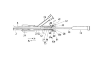
- FIG. 1 is a side view showing an appearance of a medical catheter device according to the present invention.
- FIG. 2 is a side sectional view showing a catheter and a sheath of the catheter device according to the present invention, in a state where a balloon on the distal end side of the catheter and a stent mounted on the balloon are covered with the sheath.
- FIG. 3 is a side view showing a catheter constituting the catheter device according to the present invention. 4 is a cross-sectional view taken along line IV-IV in FIG.
- FIG. 5 is a side view showing a state in which the first tubular body constituting the guide wire pull-out guide mechanism is connected to the catheter.
- FIG. 1 is a side view showing an appearance of a medical catheter device according to the present invention.
- FIG. 2 is a side sectional view showing a catheter and a sheath of the catheter device according to the present invention, in a state where a balloon on the distal end side of the catheter and a stent mounted on the balloon
- FIG. 6 is a perspective view showing a guide wire pull-out guide mechanism when a balloon on the distal end side of the catheter and a stent mounted on the balloon are covered with a sheath.
- FIG. 7 is a perspective view showing a guide wire pull-out guide mechanism in a state where a balloon on the distal end side of the catheter and a stent mounted on the balloon face the outside of the sheath.
- FIG. 8 is a cross-sectional view showing a movement restricting portion that restricts movement of the sheath relative to the catheter, and a state where movement of the sheath toward the distal end of the catheter is restricted.
- FIG. 9 is a side sectional view showing a state in which the balloon on the distal end side of the catheter and the stent mounted on the balloon face the outside of the sheath so that the stent on the balloon can be expanded.
- FIG. 10 is a cross-sectional view showing a movement restricting portion that restricts the movement of the heel sheath relative to the catheter, in a state where the sheath is moved with respect to the catheter and the stent mounted on the distal end side of the catheter is projected from the distal end of the sheath.
- FIG. 11 is a cross-sectional view showing a state where the distal end side of the sheath protrudes from the distal end of the catheter.
- the present invention is useful for use in percutaneous angioplasty (PTA), which is a surgery that expands a stenotic part generated in a blood vessel such as a blood vessel of a living body to improve blood flow.
- PTA percutaneous angioplasty
- An example applied to a catheter device for use will be described.
- the catheter device according to the present invention includes a protective sheath 1 and a catheter 2 inserted into the sheath 1 so as to be relatively movable.
- the catheter 2 constituting this catheter device is formed as a long tubular body having an outer diameter R1 of about 1 to 2 mm and a total length of about 70 to 150 cm, as shown in FIGS.
- the catheter 2 is formed so as to be inserted while being bent or deformed following a blood vessel such as a curved or bent biological blood vessel.
- the catheter 2 may be a vascular one that has been widely used conventionally.
- the sheath 1 is also made of a material that bends and deforms along the longitudinal direction. In the present embodiment, the sheath 1 is formed of a polyamide resin.
- a balloon 3 that is expanded by supplying an expansion medium such as a contrast medium is attached to the distal end side of the catheter 2.
- a stent 4 to be implanted at a desired position in the blood vessel is mounted on the outer peripheral side of the balloon 3.
- the stent 4 is formed in a cylindrical shape constituting one flow path from one end side to the other end side, for example, using a linear body made of biodegradable polymer.
- the stent 4 formed in a cylindrical shape is attached to the outer peripheral side of the balloon 3, and the diameter of the balloon 4 is expanded as the balloon 3 is expanded.
- the insertion guide member 5 is attached to the distal end portion of the catheter 2.
- the insertion guide member 5 is provided for the purpose of realizing smooth insertion of the catheter device into a blood vessel such as a blood vessel and for the purpose of restricting the sheath 1 from projecting toward the distal end side of the catheter 2.
- the part side has an outer diameter substantially equal to the outer diameter of the sheath 1, and is formed to be tapered toward the distal end side.
- a through-hole for inserting a guide wire 9 described later is formed at the center of the insertion guide member 5.
- one end side of the stent 4 mounted on the balloon 3 is supported by the stent holding member 6.
- the stent holding member 6 prevents positional displacement with respect to the balloon 3 when the diameter of the stent 4 is expanded, and surely expands the diameter following the expansion of the balloon 3.
- the catheter 2 is provided with an expansion medium supply passage 7 through which an expansion medium for expanding the balloon 3 attached to the distal end side is distributed (see FIG. 4).
- the expansion medium supply passage 7 is formed as a continuous communication passage from the proximal end side of the catheter 2 to the distal end portion side where the balloon 3 is provided. Further, as shown in FIG. 3, a through hole 8 communicating with the expansion medium supply passage 7 is formed in a portion of the catheter 2 to which the balloon 3 is attached. The expansion medium supplied to the expansion medium supply passage 7 is filled in or sucked into the balloon 3 through the through hole 8.
- a guide wire insertion passage 10 through which a guide wire 9 for guiding the insertion direction of the catheter 2 is inserted in a portion extending from the distal end portion to the middle portion of the catheter 2 when the catheter 2 is inserted into a blood vessel of a living body. Is formed. Therefore, as shown in FIG. 4, in the portion extending from the distal end side of the catheter 2 to the middle portion, two passages of the expansion medium supply passage 7 and the guide wire insertion passage 10 are formed independently and in parallel with each other. It is configured as a two-passage catheter.
- the guide wire insertion passage 10 is formed such that the opening end on the distal end side faces the distal end portion of the catheter 2 and the opening end on the proximal end side faces the middle portion of the catheter 2.
- the opening end on the proximal end side is used as a guide wire lead-out opening 11 for leading the guide wire 9 inserted into the catheter 2 to the outside of the catheter 2.
- the portion of the catheter 2 where the guide wire lead-out opening 11 is formed is formed as a bulging portion 12 bulging so as to be gradually inclined toward the side.
- the guide wire insertion passage 10 is formed over a range from 10 cm to 40 cm from the distal end of the catheter 2. Therefore, the guide wire lead-out opening 11 is formed at a position of 10 cm to 40 cm from the distal end of the catheter 2.
- a guide wire for drawing out the guide wire 9 led out from the guide wire lead-out opening 11 to the outside of the sheath 1 is used.
- An opening 13 is formed.
- the guide wire lead-out opening 11 formed in the catheter 2 and the guide wire lead-out opening 13 formed in the sheath 1 are provided.
- a guide wire drawing guide mechanism 14 for guiding the guide wire 9 led out from the guide wire lead-out opening 11 to the guide wire lead-out opening 13 is provided.
- the guide wire pull-out guide mechanism 14 is configured to advance and retreat following the relative movement of the sheath 1 with respect to the catheter 2 and to change the length from the guide wire lead-out opening 11 to the guide wire pull-out opening 13. Yes.
- the guide wire withdrawal guide mechanism 14 changes its length in accordance with the change in the distance between the guide wire lead-out opening 11 and the guide wire withdrawal opening 13 due to the relative movement of the sheath 1 and the catheter 2.
- the guide wire 9 pulled out from the catheter 2 to the sheath 1 can be pulled out while maintaining a straight state without being bent or bent halfway.
- the guide wire withdrawal guide mechanism 14 connects the proximal end side to the guide wire lead-out opening 11 formed in the catheter 2, and extends along the outer peripheral surface of the catheter 2.
- the proximal end side of the first tubular body 15 ⁇ ⁇ disposed so as to extend toward the guide wire drawing opening 13 formed in the sheath 1 and the guide wire drawing opening 13 formed in the sheath 1
- the second tubular body 16 is connected and disposed so as to extend toward the guide wire lead-out opening 11 formed in the catheter 2 along the inner peripheral surface of the sheath 1.
- the first and second tubular bodies 15 and 16 are formed of hollow tubular bodies having an inner diameter sufficient to allow the guide wire 9 to be inserted therethrough.
- the tubular bodies 15 and 16 used here have a smooth inner periphery with little friction so that a guide wire 9 formed of a thin metal wire having a thickness of about 0.3 mm to 0.6 mm can be smoothly inserted. It is desirable to form by a synthetic resin tube having a surface.
- the first and second tubular bodies 15 and 16 are made of polyimide resin.
- the first tubular body 15 is connected to the catheter 2 so that the opening end on one end side is fitted to the guide wire lead-out opening 11, and extends along the outer peripheral surface of the catheter 2.
- the catheter 2 is disposed so as to extend toward the proximal end side.
- the base end side of the first tubular body 15 is fitted into the outer peripheral side of the catheter 2 as shown in FIG. 5. 17 is fastened to the catheter 2.
- the second tubular body 16 is connected to the sheath 1 by joining the end surface on the base end side to the peripheral edge of the guide wire drawing opening 13. At this time, the second tubular body 16 is disposed along the inner peripheral surface of the sheath 1 so that the distal end side is directed to the guide wire leading opening 11.
- the second tubular body 16 is connected to the sheath 1 via a connecting member 18 made of synthetic resin, as shown in FIGS.
- the connecting member 18 is connected to the second tubular body 16 with one end fitted to the proximal end side of the second tubular body 16.
- the connecting member 18 is connected to the inner peripheral surface of the sheath 1 by joining the proximal end surface 18 a to the peripheral edge of the guide wire drawing opening 13.
- the second tubular body 16 is connected to the sheath 1 by joining a connecting member 18 connected to the base end side to the sheath 1.
- the joining of the connecting member 18 to the sheath 1 is performed using a heat welding method in which a part of the connecting member 18 and the sheath 1 is melted and joined.
- the connecting member 18 joins the entire periphery of the base end surface 18 a to the entire periphery of the peripheral edge of the guide wire drawing opening 13.
- the guide wire drawing opening 13 is hermetically sealed, so that leakage of liquid such as physiological saline injected into the sheath 1 can be prevented, and air can be completely removed from the catheter device.
- an integration port 19 communicating with the expansion medium supply passage 7 is provided at the proximal end portion of the catheter 2 inserted through the sheath 1.
- an indeflator is connected to the integration port 19 and an expansion medium for expanding the balloon 3 is supplied.
- the expansion medium supplied from the indeflator flows through the expansion medium supply passage 7 from the integration port 19 and is filled into the balloon 3 through the through hole 8 formed in the portion of the catheter 2 where the balloon 3 is attached.
- This balloon 3 is expanded.
- the stent 4 mounted on the outer peripheral side of the balloon 3 is expanded in diameter as the balloon 3 is expanded.
- a bending deformation restricting member 20 for restricting the bending deformation of the catheter 2 is attached to the proximal end portion of the catheter 2 to which the integration port 19 is attached.
- the bending deformation restricting member 20 is for restricting the bending deformation of the catheter 2 when the sheath 1 is advanced / retreated with respect to the catheter 2 and realizes a smooth advance / retreat operation, and easily deforms and bends. It is formed as a hollow tube from a highly rigid material such as aluminum or stainless steel, and is attached so as to be inserted into the outer peripheral side of the catheter 2.
- the connecting member 21 As described above, on the proximal end side of the sheath 1 into which the catheter 2 provided with the balloon 3 to which the stent 4 is attached is inserted so as to be able to advance and retreat, the connecting member 21 from which the proximal end side of the catheter 2 is pulled out. It is attached.
- the connecting member 21 injects a catheter drawing port 22 for pulling out the catheter 2 inserted through the sheath 1 and a liquid such as physiological saline supplied into the sheath 1 to remove air in the sheath 1. Integration port 23 is provided.
- the connecting member 21 is attached to the sheath 1 via a connecting hub 24 attached to the proximal end portion of the sheath 1.
- the proximal end portion of the catheter drawing port 22 of the connecting member 21 is provided with a crimping fixing mechanism 25 that constitutes a fixing means for fixing the relative movement between the catheter 2 drawn from the proximal end portion of the sheath 1 and the sheath 1. Yes.
- the proximal end side of the sheath 1 is configured by a tubular connection auxiliary member 51 having rigidity.
- the connection assisting member 51 is provided to prevent bending deformation on the proximal end side of the sheath 1, and is formed of a metallic tubular member such as stainless steel or aluminum.
- the crimping fixing mechanism 25 includes a catheter clamping member 26 formed of an elastic member such as rubber through which the catheter 2 is inserted, and a clamping member held so that the catheter clamping member 26 is accommodated.
- a holding part 27 and a compression fixture 28 for compressing the catheter clamping member 26 are provided.
- the catheter clamping member 26 is formed in a ring shape having a catheter insertion hole 29 through which the catheter 2 passes.
- the fastening member holding portion 27 is integrally provided so as to expand the diameter of the proximal end side of the catheter extraction port 22.
- the catheter clamping member 26 is housed so as to contact the bottom 27a of the clamping member holding part 27.
- the compression fixture 28 is attached to the fastening member holding portion 27 so as to be able to advance and retreat, and forms a cylindrical fitting portion 31 having a screw portion 30a formed on the inner peripheral surface and a screw portion 30b on the outer peripheral surface.
- the tightening member holding portion 27 is screwed onto and attached.
- On the proximal end side of the fitting portion 31, a rotation operation portion 32 for rotating the compression fixture 28 is provided on the proximal end side of the fitting portion 31, a rotation operation portion 32 for rotating the compression fixture 28 is provided.
- a compression operating portion 33 for compressing the catheter fastening member 26 housed in the fastening member holding portion 27 and crimping it to the catheter 2 inserted through the catheter fastening member 26.
- the compression operation part 33 is located in the inner peripheral part of the fitting part 31, and is formed in the cylindrical shape coaxial with the fitting part 31. As shown in FIG. The catheter 2 is inserted through the compression operation unit 33. Then, when the compression fixture 28 is screwed into the fastening member holding part 27, the compression operation part 33 advances into the fastening member holding part 27 and compresses the catheter fastening member 26.
- the catheter clamping member 26 is pressed by the crimping operation portion 33 and pressed against the bottom portion 27a of the clamping member holding portion 27, whereby the catheter insertion hole 29 is reduced in diameter by being crushed while restricting expansion of the outer peripheral diameter. And crimping to the catheter 2.
- the catheter 2 is restricted from advancing and retreating with respect to the sheath 1 when the catheter fastening member 26 is crimped, the insertion position with respect to the sheath 1 is fixed, and the relative movement of the sheath 1 with respect to the catheter 2 is restricted.
- the catheter clamping member 26 is crimped to the catheter 2, the inside of the clamping member holding portion 27 is sealed.
- a liquid such as physiological saline injected from the integration port 23 is prevented from leaking from the catheter extraction port 22 and is supplied into the sheath 1.
- the catheter 2 whose insertion position is fixed with respect to the sheath 1 can be moved relative to the sheath 1 by releasing the tightening by the crimping fixing mechanism 25. Release of the clamping of the catheter 2 by the crimping fixing mechanism 25 is performed by rotating the compression fixture 28, withdrawing the crimping operation part 33 from the catheter clamping member 26, and releasing the compression of the catheter clamping member 26.
- the first tubular body 15 constituting the guide wire pulling guide mechanism 14 has a sheath 1 with respect to the catheter 2 as shown by an arrow in FIG.
- the balloon 3 provided on the distal end side of the catheter 2 faces the outside of the sheath 1 and can be inflated as shown in FIG. 9, the distal end side of the catheter 2 is placed on the sheath 1.
- It is formed as a tubular body that has an overlapping length L2 that protrudes from the distal end side and faces the outside, and has an overlapping length L2 (see FIGS. 2, 6, and 10).
- the sheath 1 is moved away from the distal end side of the catheter 2 on which the balloon 3 is provided and exposed to the outside so that the sheath 1 faces the outside in FIG. Even if it is a case where it pulls back to the operator side of a X1 direction, the connection state of the 1st and 2nd tubular bodies 15 and 16 can be maintained. Therefore, even when the operation of pulling out the sheath 1 from the catheter 2 is performed and the distance between the guide wire lead-out opening 11 and the guide wire lead-out opening 13 is changed, the first and second tubular bodies 15 are used. , 16 are always maintained, and the guide wire 9 can be reliably pulled out to the side of the sheath 1.
- the catheter device projects the stent 4 accommodated in the sheath 1 together with the balloon 3 to the distal end portion of the catheter 2, so that the fixation by the crimping fixing mechanism 25 is released.
- the sheath 1 is moved with respect to the catheter 2, it is possible to prevent the sheath 1 from being pushed out of the catheter 2 in the direction of the arrow X2 in FIG. 2 and the distal end of the catheter 2 is the inner wall of the blood vessel. If the catheter device is forcibly inserted into the blood vessel in contact with the catheter, only the sheath 1 moves, moves over the insertion guide member 5 provided at the distal end of the catheter 2 and moves forward of the catheter 2.
- the 1st movement control part 35 for preventing it is provided.
- the first movement restricting portion 35 is provided between the sheath 1 and the catheter 2 that move relative to each other.
- the first movement restricting portion 35 includes a first contact locking portion 36 provided on the sheath 1 and a movement restricting member 37 provided on the catheter 2.
- the first abutment locking portion 36 constituting the first movement restricting portion 35 is used to pull out the catheter of the connecting member 21 attached to the proximal end portion of the sheath 1. It is comprised by the latching step part formed in the port 22 for an operation.
- the abutment locking portion 36 is formed on the proximal end side of the catheter extraction port 22 to which the crimping fixing mechanism 25 is attached.
- the movement restricting member 37 is constituted by a member attached to the outer peripheral portion of the catheter 2 so as to increase the outer peripheral diameter of the catheter 2 as shown in FIG.
- the movement restricting member 37 is attached to the outer peripheral side of the bending deformation restricting member 20 attached to the proximal end portion of the catheter 2.
- the first movement restricting portion 35 abuts the first abutting locking portion 36 on one abutting surface 38 located on the proximal end side of the movement restricting member 37.
- the sheath 1 places the distal end portion 1 a in contact with the proximal end portion of the insertion guide member 5 and stores the stent 4 on the balloon 3.
- the movement restricting member 37 has the distal end portion 1 a of the sheath 1 at the proximal end portion of the insertion guide member 5 when the first contact locking portion 36 on the sheath 1 side contacts one contact surface 38. It forms in the outer peripheral part of the catheter 2 so that it may contact
- the catheter device restricts the amount of the sheath 1 that can be pulled out of the catheter 2 and prevents the connection state of the first and second tubular bodies 15 and 16 from being released.
- a movement restriction unit 40 is provided.
- the second movement restricting portion 40 includes a second contact locking portion 41 provided on the sheath 1 side and a movement restricting member 37 attached to the outer peripheral portion of the catheter 2.
- the second abutment locking portion 41 is configured by an end surface on the proximal end side of the hub 24 that connects the connection member 21 to the sheath 1.
- the sheath 1 is configured so that the second contact locking portion 41 contacts the other contact surface 42 located on the proximal end side of the movement restricting member 37, thereby The movement in the arrow X1 direction in FIG. 10 is restricted.
- the sheath 1 is pulled out in the pulling direction of the arrow X1 in FIG. 10 with respect to the catheter 2, and the second tubular body 16 is pulled out of the first tubular body 15 in FIG. It is provided at a position that restricts the movement of the sheath 1 relative to the catheter 2 so that the overlapping of the first tubular body 15 and the second tubular body 16 is not released when moved in the pulling direction of the arrow X1. Yes.
- the movement distance L1 in the pulling direction in the direction of the arrow X1 in FIG. 10 with respect to the catheter 2 of the sheath 1 is equal to or less than the overlapping length L2 of the first tubular body 15 and the second tubular body 16. It is formed to become.
- the movement distance L1 of the sheath 1 relative to the catheter 2 corresponds to a length L3 that allows the stent 4 mounted on the balloon 3 to face the outside of the sheath 1 as shown in FIG.
- the diameter of the balloon 3 can be expanded by expanding the balloon 3.
- the amount of movement of the sheath 1 relative to the catheter 2 becomes constant, and the sheath 1 can reliably support the balloon 3.
- the diameter of the stent 4 can be expanded.
- the sheath 1 is moved relative to the catheter 2 in the direction of the arrow X1 in FIG. 9 until the second contact locking portion 41 contacts the other contact surface 42 of the movement restricting member 37.
- the stent 4 mounted on the balloon 3 provided on the distal end side of the catheter 2 is projected from the distal end portion of the sheath 1 to the outside. Therefore, the second contact locking portion 41 and the other contact surface 42 of the movement restricting member 37 are arranged so that the first contact locking portion 36 on the sheath 1 side is one contact surface 38 of the movement restricting member 37.
- the stent 4 mounted on the balloon 3 is formed so as to have an interval that can move a movement distance L1 corresponding to a length L3 that allows the sheath 1 to face the outside. .
- the stent 4 mounted on the balloon 3 provided on the distal end side of the catheter 2 is securely held by the sheath 1 by being mounted in a reduced diameter state. Further, it is possible to prevent the balloon 3 from dropping off or being displaced.
- the implantation of the stent 4 in the blood vessel of the living body using the catheter device according to the present invention as described above is performed in the following procedure.
- a catheter device having a stent 4 mounted on a balloon 3 is prepared.
- the stent 4 is held so as to be mounted on the balloon 3 in a reduced state in a reduced state and accommodated in the sheath 1.
- the catheter 2 is pulled into the sheath 1, is fixed to the sheath 1 by the crimping fixing mechanism 25, and is placed in a state where relative movement is restricted.
- the first abutment locking portion 36 constituting the first movement restricting portion 35 abuts against one abutment surface 38 of the movement restricting member 37, and the sheath 1 is shown in FIG. 8, the movement of the catheter 2 in the direction of the middle arrow X2 in the direction of the distal end is restricted.
- the proximal end portion of the guide wire 9 inserted in advance in the stenosis portion of the blood vessel is inserted into the guide wire insertion passage 10 from the distal end side of the catheter 2.
- the guide wire 9 enters the first tubular body 15 from the guide wire outlet opening 11 provided on the proximal end side of the guide wire insertion passage 10.
- the guide wire 9 inserted through the first tubular body 15 is introduced into a second tubular body 16 that is connected to the first tubular member 15 and constitutes the guide wire pull-out guide mechanism 14.
- the guide wire 9 introduced into the second tubular body 16 is drawn to the side of the sheath 1 through the guide wire drawing opening 13.
- the catheter 2 In a state where the end portion of the guide wire 9 drawn out to the side of the sheath 1 is held and fixed, the catheter 2 is inserted into the blood vessel along the guide wire 9 and attached to the distal end portion of the catheter 2. Then, the stent 4 mounted on the balloon 3 is positioned in the stenosis portion that is the implantation position. At this time, the catheter 2 is inserted into the blood vessel together with the sheath 1.
- the crimping fixing mechanism 25 is operated to release the fixation of the sheath 1 and the catheter 2, and the sheath 1 is fixed to the catheter 2 with the arrow X1 in FIGS.
- the balloon 3 is exposed to the distal end side of the sheath 1 together with the stent 4.
- the balloon 3 can be expanded, and the diameter of the stent 4 mounted on the balloon 3 can be increased.
- the operation may be erroneously pushed out of the catheter 2 in the direction of the arrow X2 in FIG.
- the catheter device is further forcibly inserted into the blood vessel in a state in which the distal end portion of the catheter 2 is in contact with the inner wall of the blood vessel, only the sheath 1 moves, and the insertion guide member provided at the distal end of the catheter 2 5 and move forward of the catheter 2.
- the insertion guide member 5 is fitted into the sheath 1, and smooth movement of the sheath 1 with respect to the catheter 2 becomes difficult.
- the stent 4 supported by the catheter 2 may protrude from the sheath 1 and may not be implanted at a desired implantation position.
- the first movement restricting portion 35 prevents the distal end portion 1a of the sheath 1 from getting over the insertion guide member 5 and protruding from the distal end side of the catheter 2. . This reliably prevents the operation of pushing the sheath 1 toward the distal end side of the catheter 2, realizes a safe insertion operation into the blood vessel, and reliably implants the stent 4 on the balloon 3 at a predetermined implantation position. Is possible.
- the second tubular body 16 together with the sheath 1 moves from the first tubular body 15 with the arrow X1 in FIG.
- the second tubular body 16 is pulled out from the first tubular body 15.
- the first and second tubular bodies 15 and 16 move so that the sheath 1 moves relative to the catheter 2 to release the support of the distal end portion where the balloon 3 is provided and to face the outside.
- the overlapping length L2 which is equal to or longer than the possible distance L1 is overlapped and connected.
- the first and second tubular bodies 15 and 16 have the sheath 1 with respect to the catheter 2 by a length L1 sufficient to release the support on the distal end side where the balloon 3 of the catheter 2 is provided and face the outside. Even if they are pulled back, they can be connected to each other. And the 1st and 2nd tubular bodies 15 and 16 can maintain a connection state always, and can guide the guide wire 9 by inserting in them.
- the expansion medium is supplied through the expansion medium supply passage 7 provided in the catheter 2 using an inflator or the like, and the balloon 3 is transmitted through the through hole 8.
- the balloon 3 is inflated.
- the diameter of the stent 4 mounted on the balloon 3 is expanded.
- the stent 4 is in a state where the inner wall of the blood vessel is supported from the inside by being expanded in diameter.
- the expansion medium filled in the balloon 3 is extracted through the expansion medium supply passage 7 and contracted under reduced pressure.
- the expanded stent 4 maintains the expanded state, is detached from the contracted balloon 3, is placed in the stenosis portion in the blood vessel, and maintains the state of supporting the inner wall of the blood vessel to be implanted. Complete.
- the sheath 1 when the sheath 1 is pulled back with respect to the catheter 2 in order to make the stent 4 on the balloon 3 face the outside, the sheath 1 is as shown in FIG.
- the second abutment locking portion 41 abuts on the other abutment surface 42 located on the proximal end side of the movement restricting member 37, and the movement of the catheter 2 in the direction of the arrow X1 in FIG. Therefore, the protruding position of the stent 4 from the distal end portion of the catheter 2 on the balloon 3 can be accurately regulated, and the stent 4 is reliably exposed to the outside of the sheath 1 and the balloon 3 is inflated reliably.
- the stent can be expanded in diameter. Furthermore, the connection state of the 1st and 2nd tubular bodies 15 and 16 can be maintained reliably, and the insertion guide by the guide wire 9 can be maintained.
- the catheter 2 and the sheath 1 are pulled out from the blood vessel along the guide wire 9.
- the guide wire 9 is led out from the middle part of the sheath 1 covering the catheter 2, a quick extraction operation can be performed without using an extension guide wire.
- the advantages of the monorail catheter device can be realized while including the sheath 1 that holds the stent 4 mounted on the balloon 3 provided in the catheter 2.
- the catheter device ensures that the stent 4 mounted on the balloon 3 provided on the catheter 2 is displaced and dropped while effectively utilizing the advantages of the monorail balloon catheter.
- the stent 4 can be safely and reliably implanted at a desired lesion site by preventing damage to blood vessels and the like.
- the stent 4 can be quickly implanted into a blood vessel such as a blood vessel of a living body.
- the present invention has been described with reference to an example in which the present invention is applied to a monorail catheter device.
- an over-the-guide wire insertion hole formed over the entire length from the distal end side to the proximal end side of the catheter. It can also be applied to a wire type catheter device, and even when applied to an over-the-wire type catheter device, the distal end portion of the catheter 2 with the distal end side of the sheath 1 getting over the insertion guide member 5 It is possible to accurately control the protruding position of the stent 4 on the balloon 3 from the distal end portion of the catheter 2, and to prevent damage to blood vessels and the like safely, It is possible to reliably implant the stent 4 at a desired lesion site.
- the catheter device according to the present invention can be widely used not only for blood vessels but also for implanting stents in vascular vessels such as ureters and bile ducts.
Abstract
Priority Applications (5)
| Application Number | Priority Date | Filing Date | Title |
|---|---|---|---|
| AU2011335994A AU2011335994A1 (en) | 2010-11-29 | 2011-11-11 | Medical catheter device |
| US13/885,301 US20130345787A1 (en) | 2010-11-29 | 2011-11-11 | Medical catheter apparatus |
| KR1020137013069A KR20130140025A (ko) | 2010-11-29 | 2011-11-11 | 의료용 카테터 장치 |
| EP11845843.9A EP2647357A1 (fr) | 2010-11-29 | 2011-11-11 | Dispositif cathéter médical |
| JP2012546676A JPWO2012073434A1 (ja) | 2010-11-29 | 2011-11-11 | 医療用のカテーテル装置 |
Applications Claiming Priority (2)
| Application Number | Priority Date | Filing Date | Title |
|---|---|---|---|
| JP2010-264699 | 2010-11-29 | ||
| JP2010264699 | 2010-11-29 |
Publications (1)
| Publication Number | Publication Date |
|---|---|
| WO2012073434A1 true WO2012073434A1 (fr) | 2012-06-07 |
Family
ID=46171411
Family Applications (1)
| Application Number | Title | Priority Date | Filing Date |
|---|---|---|---|
| PCT/JP2011/006328 WO2012073434A1 (fr) | 2010-11-29 | 2011-11-11 | Dispositif cathéter médical |
Country Status (6)
| Country | Link |
|---|---|
| US (1) | US20130345787A1 (fr) |
| EP (1) | EP2647357A1 (fr) |
| JP (1) | JPWO2012073434A1 (fr) |
| KR (1) | KR20130140025A (fr) |
| AU (1) | AU2011335994A1 (fr) |
| WO (1) | WO2012073434A1 (fr) |
Cited By (2)
| Publication number | Priority date | Publication date | Assignee | Title |
|---|---|---|---|---|
| WO2015055070A1 (fr) * | 2013-10-14 | 2015-04-23 | 黄景陶 | Dispositif de placement capable de positionner précisément une endoprothèse endoluminale dans le corps humain |
| WO2018207542A1 (fr) * | 2017-05-11 | 2018-11-15 | 株式会社 京都医療設計 | Dispositif de mise en place d'endoprothèse |
Families Citing this family (11)
| Publication number | Priority date | Publication date | Assignee | Title |
|---|---|---|---|---|
| CA2955841C (fr) | 2014-09-10 | 2017-06-27 | Vascular Solutions, Inc. | Ensemble et procede de capture |
| KR101536244B1 (ko) * | 2014-10-30 | 2015-07-13 | 주식회사 엠아이텍 | 카테터 |
| KR101696811B1 (ko) * | 2015-02-10 | 2017-01-17 | 주식회사 엠아이텍 | 카테터 |
| JP6585700B2 (ja) * | 2015-03-03 | 2019-10-02 | 株式会社塚田メディカル・リサーチ | バルーンカテーテル用ユニット及び尿道留置バルーンカテーテル |
| EP3275495A4 (fr) * | 2015-03-25 | 2018-12-05 | Olympus Corporation | Instrument de traitement |
| EP3397207A4 (fr) * | 2015-12-30 | 2019-09-11 | Mitralign, Inc. | Système et procédé de réduction de régurgitation tricuspide |
| KR101863192B1 (ko) * | 2016-12-05 | 2018-06-29 | 주식회사 티앤알바이오팹 | 3d프린팅 스텐트 시술용 카테터, 시술용 카테터를 고정하기 위한 지그 및 이를 이용한 3d프린팅 스텐트 제조방법 |
| KR102183544B1 (ko) | 2018-10-30 | 2020-11-27 | 한빛바이오 주식회사 | 내시경 일체형의 일회용 경막외 수술 장치 |
| KR102182074B1 (ko) | 2019-12-24 | 2020-11-23 | 김남배 | 내시경 일체형 경막외 수술 기구의 제작 방법 및 이에 의해 제작된 내시경 일체형 경막외 수술 기구 |
| CA3141882A1 (fr) * | 2020-04-13 | 2021-10-21 | Edwards Lifesciences Corporation | Appareil d'administration endovasculaire ayant un ballonnet a longueur variable |
| CN113599037A (zh) * | 2021-08-27 | 2021-11-05 | 苏州中天医疗器械科技有限公司 | 一种快速交换式球囊支架安装装置及支架安装方法 |
Citations (5)
| Publication number | Priority date | Publication date | Assignee | Title |
|---|---|---|---|---|
| JP2002102359A (ja) * | 2000-10-02 | 2002-04-09 | Terumo Corp | 生体器官拡張用器具 |
| WO2004013450A1 (fr) | 2002-08-06 | 2004-02-12 | Ceratizit Austria Aktiengesellschaft | Foret, notamment foret a pierre |
| WO2004103450A1 (fr) | 2003-05-23 | 2004-12-02 | Kabushikikaisha Igaki Iryo Sekkei | Dispositif d'amenee de stent |
| JP2006503671A (ja) * | 2002-10-26 | 2006-02-02 | アルヴィオラス,インコーポレイテッド | 医療器具送達装置および使用方法 |
| JP2010233934A (ja) * | 2009-03-31 | 2010-10-21 | Terumo Corp | 生体器官病変部改善用器具 |
Family Cites Families (13)
| Publication number | Priority date | Publication date | Assignee | Title |
|---|---|---|---|---|
| US5389087A (en) * | 1991-09-19 | 1995-02-14 | Baxter International Inc. | Fully exchangeable over-the-wire catheter with rip seam and gated side port |
| JPH08500757A (ja) * | 1992-12-30 | 1996-01-30 | シュナイダー・(ユーエスエイ)・インコーポレーテッド | 身体に移植可能なステントを展開する装置 |
| IL140870A0 (en) * | 2001-01-11 | 2002-02-10 | Mind Guard Ltd | Deployment system for implantable self-expandable intraluminal devices |
| US7611528B2 (en) * | 2003-01-24 | 2009-11-03 | Medtronic Vascular, Inc. | Stent-graft delivery system |
| US7947070B2 (en) * | 2003-05-16 | 2011-05-24 | Boston Scientific Scimed, Inc. | Dilatation and stent delivery system and related methods |
| US8317859B2 (en) * | 2004-06-28 | 2012-11-27 | J.W. Medical Systems Ltd. | Devices and methods for controlling expandable prostheses during deployment |
| JP4804780B2 (ja) * | 2005-03-28 | 2011-11-02 | テルモ株式会社 | 生体器官拡張器具 |
| JP2007044141A (ja) * | 2005-08-08 | 2007-02-22 | Olympus Medical Systems Corp | 内視鏡用カテーテル |
| EP1948288B1 (fr) * | 2005-11-14 | 2009-12-23 | Abbott Laboratories Vascular Enterprises Limited | Sonde a ballonnet avec segment elastique |
| US20070208350A1 (en) * | 2006-03-06 | 2007-09-06 | Gunderson Richard C | Implantable medical endoprosthesis delivery systems |
| US20080140175A1 (en) * | 2006-12-07 | 2008-06-12 | Boucher Donald D | Spring stop for stent delivery system and delivery system provided with same |
| JP5248165B2 (ja) * | 2008-03-31 | 2013-07-31 | テルモ株式会社 | 生体内留置用ステントおよび生体器官拡張器具 |
| EP2481379B1 (fr) * | 2009-09-25 | 2017-03-01 | Kyoto Medical Planning Co., Ltd. | Dispositif de cathéter médical |
-
2011
- 2011-11-11 AU AU2011335994A patent/AU2011335994A1/en not_active Abandoned
- 2011-11-11 US US13/885,301 patent/US20130345787A1/en not_active Abandoned
- 2011-11-11 JP JP2012546676A patent/JPWO2012073434A1/ja active Pending
- 2011-11-11 WO PCT/JP2011/006328 patent/WO2012073434A1/fr active Application Filing
- 2011-11-11 KR KR1020137013069A patent/KR20130140025A/ko not_active Application Discontinuation
- 2011-11-11 EP EP11845843.9A patent/EP2647357A1/fr not_active Withdrawn
Patent Citations (5)
| Publication number | Priority date | Publication date | Assignee | Title |
|---|---|---|---|---|
| JP2002102359A (ja) * | 2000-10-02 | 2002-04-09 | Terumo Corp | 生体器官拡張用器具 |
| WO2004013450A1 (fr) | 2002-08-06 | 2004-02-12 | Ceratizit Austria Aktiengesellschaft | Foret, notamment foret a pierre |
| JP2006503671A (ja) * | 2002-10-26 | 2006-02-02 | アルヴィオラス,インコーポレイテッド | 医療器具送達装置および使用方法 |
| WO2004103450A1 (fr) | 2003-05-23 | 2004-12-02 | Kabushikikaisha Igaki Iryo Sekkei | Dispositif d'amenee de stent |
| JP2010233934A (ja) * | 2009-03-31 | 2010-10-21 | Terumo Corp | 生体器官病変部改善用器具 |
Cited By (2)
| Publication number | Priority date | Publication date | Assignee | Title |
|---|---|---|---|---|
| WO2015055070A1 (fr) * | 2013-10-14 | 2015-04-23 | 黄景陶 | Dispositif de placement capable de positionner précisément une endoprothèse endoluminale dans le corps humain |
| WO2018207542A1 (fr) * | 2017-05-11 | 2018-11-15 | 株式会社 京都医療設計 | Dispositif de mise en place d'endoprothèse |
Also Published As
| Publication number | Publication date |
|---|---|
| AU2011335994A1 (en) | 2013-06-06 |
| KR20130140025A (ko) | 2013-12-23 |
| EP2647357A1 (fr) | 2013-10-09 |
| US20130345787A1 (en) | 2013-12-26 |
| JPWO2012073434A1 (ja) | 2014-05-19 |
Similar Documents
| Publication | Publication Date | Title |
|---|---|---|
| WO2012073434A1 (fr) | Dispositif cathéter médical | |
| JP4798675B2 (ja) | 医療用のカテーテル装置 | |
| US11382743B2 (en) | Delivery apparatus for prosthetic heart valve | |
| CA2476734C (fr) | Procede et dispositif permettant la mise en place d'un dispositif endoluminal | |
| EP1067886B1 (fr) | Dispositif de mise en place d'endoprothese a action reversible | |
| US8465536B2 (en) | Prosthesis deployment system | |
| US5476505A (en) | Coiled stent and delivery system | |
| US7331985B2 (en) | Apparatus and method for deployment of an endoluminal device | |
| KR101194688B1 (ko) | 스텐트 공급장치 | |
| JP4330805B2 (ja) | カテーテル組立体にステントを取り外し可能に取り付けるためのシステムとその使用方法 | |
| US6945989B1 (en) | Apparatus for delivering endoluminal prostheses and methods of making and using them | |
| US20150057738A1 (en) | Catheter system with movable sleeve | |
| US20080114435A1 (en) | Flexible delivery system | |
| JP2002527211A (ja) | ステント輸送潅流カテーテル | |
| CA3057877A1 (fr) | Catheters a ballonnet et procedes d'utilisation | |
| JP4780688B2 (ja) | 医療用のカテーテル装置 | |
| US20110046709A1 (en) | Methods for implanting a stent using a guide catheter | |
| WO2023157444A1 (fr) | Dispositif médical et méthode de traitement | |
| JP2015066007A (ja) | 医療用のカテーテル装置 |
Legal Events
| Date | Code | Title | Description |
|---|---|---|---|
| 121 | Ep: the epo has been informed by wipo that ep was designated in this application |
Ref document number: 11845843 Country of ref document: EP Kind code of ref document: A1 |
|
| WWE | Wipo information: entry into national phase |
Ref document number: 2011845843 Country of ref document: EP |
|
| ENP | Entry into the national phase |
Ref document number: 2012546676 Country of ref document: JP Kind code of ref document: A |
|
| ENP | Entry into the national phase |
Ref document number: 20137013069 Country of ref document: KR Kind code of ref document: A |
|
| NENP | Non-entry into the national phase |
Ref country code: DE |
|
| ENP | Entry into the national phase |
Ref document number: 2011335994 Country of ref document: AU Date of ref document: 20111111 Kind code of ref document: A |
|
| WWE | Wipo information: entry into national phase |
Ref document number: 13885301 Country of ref document: US |