WO2012073340A1 - 鍵更新方法、ノード、ゲートウェイ、サーバ、およびネットワークシステム - Google Patents
鍵更新方法、ノード、ゲートウェイ、サーバ、およびネットワークシステム Download PDFInfo
- Publication number
- WO2012073340A1 WO2012073340A1 PCT/JP2010/071394 JP2010071394W WO2012073340A1 WO 2012073340 A1 WO2012073340 A1 WO 2012073340A1 JP 2010071394 W JP2010071394 W JP 2010071394W WO 2012073340 A1 WO2012073340 A1 WO 2012073340A1
- Authority
- WO
- WIPO (PCT)
- Prior art keywords
- gateway
- node
- address
- key
- new key
- Prior art date
Links
Images


Classifications
-
- H—ELECTRICITY
- H04—ELECTRIC COMMUNICATION TECHNIQUE
- H04L—TRANSMISSION OF DIGITAL INFORMATION, e.g. TELEGRAPHIC COMMUNICATION
- H04L9/00—Cryptographic mechanisms or cryptographic arrangements for secret or secure communications; Network security protocols
- H04L9/08—Key distribution or management, e.g. generation, sharing or updating, of cryptographic keys or passwords
- H04L9/0816—Key establishment, i.e. cryptographic processes or cryptographic protocols whereby a shared secret becomes available to two or more parties, for subsequent use
- H04L9/0819—Key transport or distribution, i.e. key establishment techniques where one party creates or otherwise obtains a secret value, and securely transfers it to the other(s)
- H04L9/0827—Key transport or distribution, i.e. key establishment techniques where one party creates or otherwise obtains a secret value, and securely transfers it to the other(s) involving distinctive intermediate devices or communication paths
-
- H—ELECTRICITY
- H04—ELECTRIC COMMUNICATION TECHNIQUE
- H04L—TRANSMISSION OF DIGITAL INFORMATION, e.g. TELEGRAPHIC COMMUNICATION
- H04L63/00—Network architectures or network communication protocols for network security
- H04L63/06—Network architectures or network communication protocols for network security for supporting key management in a packet data network
- H04L63/068—Network architectures or network communication protocols for network security for supporting key management in a packet data network using time-dependent keys, e.g. periodically changing keys
-
- H—ELECTRICITY
- H04—ELECTRIC COMMUNICATION TECHNIQUE
- H04L—TRANSMISSION OF DIGITAL INFORMATION, e.g. TELEGRAPHIC COMMUNICATION
- H04L9/00—Cryptographic mechanisms or cryptographic arrangements for secret or secure communications; Network security protocols
- H04L9/08—Key distribution or management, e.g. generation, sharing or updating, of cryptographic keys or passwords
- H04L9/0891—Revocation or update of secret information, e.g. encryption key update or rekeying
Definitions
- the present invention relates to a key update method for updating a key for encrypting data, a node, a gateway, a server, and a network system.
- An ad hoc network is a type of self-configuring network that is linked by wireless communication.
- An ad hoc network is composed of a plurality of nodes. Each node in the ad hoc network transmits and receives packets by multi-hop communication. Multi-hop communication is a technique in which nodes that do not exist within each other's communication area communicate with each other via another node that exists within the communication area of each node.
- ad hoc network when connecting an ad hoc network and another network such as the Internet, LAN (Local Area Network), WAN (Wide Area Network), etc., communication between networks is transferred using a relay device called a gateway.
- LAN Local Area Network
- WAN Wide Area Network
- a node capable of wireless communication is incorporated in each home electric power meter, and a worker performs work such as meter confirmation via an ad hoc network without going to the site.
- a node capable of wireless communication is incorporated in each home electric power meter, and a worker performs work such as meter confirmation via an ad hoc network without going to the site.
- an ad hoc network that handles personal information such as the amount of power used in each home, it is required to perform secure communication from the viewpoint of confidentiality and tampering prevention.
- the new node when the new node is initially introduced into the system, the new node cannot communicate securely with other nodes in the ad hoc network until the encryption key is set. For this reason, it is difficult to automatically set an encryption key to a new node via an ad hoc network, and a worker goes to the site to set the encryption key.
- the candidate gateways can be narrowed down from the address of the node installation location, the communication status changes due to factors such as the weather and the positional relationship with nearby buildings. For this reason, it is necessary for the worker to go to the site to confirm which gateway is actually communicable, and there is a problem in that the work time and work load required for the work of updating the encryption key of the worker are increased. .
- a node adjacent to one hop can receive a broadcast packet (hereinafter, “BC packet”) from the gateway, but the BC packet is encrypted with a new encryption key (hereinafter, “new key”). ing. Therefore, the packet cannot be decrypted with the currently owned encryption key (hereinafter “current key”), and is not transferred from the gateway to the next two hops.
- BC packet broadcast packet
- new key a new encryption key
- a node that is one hop from the gateway can be set as a new key, but a key that is two hops away from the gateway cannot be set.
- a node adjacent to two hops from the gateway can update the key only after completing the key update for the node adjacent to one hop from the gateway and receiving a BC packet from the gateway.
- the present invention provides a key update method, a node, a gateway, a server, and a network system capable of improving the efficiency of updating the encryption key used by a node in an ad hoc network in order to solve the above-described problems caused by the prior art.
- the purpose is to provide.
- a gateway in an ad hoc network, a node group in the ad hoc network, and a server capable of communicating with the gateway are provided to each node of the node group.
- the gateway In updating the gateway-specific current key, the gateway simultaneously notifies the ad hoc network of an encrypted packet obtained by encrypting the current key update notification information with the current key.
- a unique new key is obtained and stored, and the server obtains the new key and stores the new key in association with the gateway address in a database that associates and stores the gateway address and the current key.
- the server configures the ad hoc network
- the address of each node in the node group is received from the gateway
- information that associates the address of the gateway and the address of each node is created, and each node in the node group sends the encrypted packet to the encrypted packet.
- the update notification information is obtained by decrypting with a current key, and a specific node connected to a portable terminal capable of communicating with the server in the node group is the update notification information. If determined, the update request packet including the address of the specific node is transmitted to the server via the mobile terminal, and the server is included in the update request packet transmitted in the database. It is determined whether the address of the node in the created information is present.
- the address of the gateway is determined.
- the new key associated with the network is extracted from the database, and the server transmits the extracted new key to the specific node via the mobile terminal, and the specific node Examples include a key update method, a node, a gateway, a server, and a network system that update the current key to the transmitted new key.
- node, gateway, server, and network system According to the key update method, node, gateway, server, and network system according to the present invention, it is possible to improve the efficiency of updating the encryption key used by the nodes in the ad hoc network.
- FIG. 1 is an explanatory diagram of an example of the network system according to the embodiment.
- FIG. 2 is an explanatory diagram (part 1) illustrating a key update example in the ad hoc network Ai.
- FIG. 3 is an explanatory diagram (part 2) of a key update example in the ad hoc network Ai.
- FIG. 4 is an explanatory diagram (part 3) illustrating a key update example in the ad hoc network Ai.
- FIG. 5 is an explanatory diagram (part 4) illustrating a key update example in the ad hoc network Ai.
- FIG. 6 is an explanatory diagram (part 5) illustrating a key update example in the ad hoc network Ai.
- FIG. 1 is an explanatory diagram of an example of the network system according to the embodiment.
- FIG. 2 is an explanatory diagram (part 1) illustrating a key update example in the ad hoc network Ai.
- FIG. 3 is an explanatory diagram (part 2) of
- FIG. 7 is an explanatory diagram showing an example of the data structure of the encrypted packet SPi broadcast from the gateway Gi.
- FIG. 8 is an explanatory diagram showing another example of the data structure of the encrypted packet SPi broadcast from the gateway Gi.
- FIG. 9 is an explanatory diagram showing an example of the data structure of the encrypted response packet RP transmitted from the node Ni to the gateway Gi.
- FIG. 10 is a block diagram of a hardware configuration example of the management server 101 according to the embodiment.
- FIG. 11 is a block diagram of a hardware configuration example of the gateway Gi and the nodes Ni-1 to Ni-mi (hereinafter “nodes”) according to the embodiment.
- FIG. 12 is an explanatory diagram showing an example of the contents stored in the key information DB 110.
- FIG. 10 is a block diagram of a hardware configuration example of the management server 101 according to the embodiment.
- FIG. 11 is a block diagram of a hardware configuration example of the gateway Gi and the nodes Ni-1 to Ni-mi (hereinafter “n
- FIG. 13 is an explanatory diagram showing an example of the contents stored in the table Ti.
- FIG. 14 is a block diagram illustrating a functional configuration example of the gateway Gi.
- FIG. 15 is a block diagram illustrating a functional configuration example of the management server 101.
- FIG. 16 is a block diagram illustrating a functional configuration example of the node Ni.
- FIG. 17 is an explanatory diagram illustrating an example of authentication information of the management server 101.
- FIG. 18 is an explanatory diagram illustrating an example of authentication information of the mobile terminal H.
- FIG. 19 is a sequence diagram illustrating a key update sequence example according to the embodiment.
- FIG. 20 is a flowchart illustrating an example of a detailed processing procedure of the key update pre-processing (step S1907) illustrated in FIG. FIG.
- FIG. 21 is a flowchart showing an example of a detailed processing procedure of the new key specifying process (step S1915) shown in FIG.
- FIG. 22 is a block diagram illustrating another example of the functional configuration of the gateway Gi.
- FIG. 23 is a block diagram illustrating another example of the functional configuration of the management server 101.
- FIG. 24 is a sequence diagram illustrating another example of the key update sequence according to the embodiment.
- FIG. 1 is an explanatory diagram of an example of the network system according to the embodiment.
- the network system 100 includes a management server 101, gateways G1 to Gn, and nodes N1-1 to N1-m1, N2-1 to N2-m2,..., Nn-1 to Nn-mn. It is a configuration.
- the management server 101 and the gateways G1 to Gn are connected to each other via a network NW1 such as the Internet, LAN, or WAN.
- NW1 such as the Internet, LAN, or WAN.
- node Ni indicates an arbitrary node among the nodes Ni-1 to Ni-mi constituting an arbitrary ad hoc network Ai.
- the management server 101 is a computer that includes a key information DB (database) 110 and manages encryption keys unique to the gateways G1 to Gn.
- the encryption key unique to the gateway Gi (hereinafter referred to as “encryption key Ki”) is key information for encrypting packets transmitted and received between nodes in the ad hoc network Ai to which the gateway Gi belongs.
- encryption key Ki is key information for encrypting packets transmitted and received between nodes in the ad hoc network Ai to which the gateway Gi belongs.
- the gateway Gi is a relay device that connects the ad hoc network Ai and the network NW1.
- the gateway Gi understands both the protocol of the ad hoc network Ai and the protocol of the network NW1, and transfers communication between the ad hoc network Ai and the network NW1.
- Nodes Ni-1 to Ni-mi are wireless communication devices that perform multi-hop communication with other nodes within a predetermined communication range.
- the gateway Gi it is not necessary for all the nodes Ni-1 to Ni-mi to directly communicate with the gateway Gi, and it is sufficient that some nodes can communicate with the gateway Gi.
- the network system 100 can be applied to, for example, a system that collects the amount of power and gas used in each household. Specifically, for example, by incorporating each node Ni-1 to Ni-mi into a power meter or gas meter in each home, the amount of power or gas used in each home is transmitted and received between nodes in the ad hoc network Ai. Note that the power consumption and gas consumption of each household may be measured by each node Ni-1 to Ni-mi, or each node Ni-1 to Ni-mi may be obtained from a power meter or gas meter. Good.
- the gateway Gi uses the power and gas usage of each home received from the nodes Ni-1 to Ni-mi in the ad hoc network Ai to the server of the power company or gas company (for example, the management server 101) via the network NW1. Send to. As a result, the amount of power and gas used can be collected without the need for workers to visit the site.
- the packet is encrypted using the encryption key Ki unique to the gateway Gi for each ad hoc network Ai. This ensures secure communication (data confidentiality, tampering prevention, etc.) of the ad hoc network Ai. Moreover, the risk at the time of key leakage is reduced by changing the encryption key Ki for every ad hoc network Ai. Since the received packet is also encrypted with the encryption key Ki, the gateway Gi and its subordinate nodes Ni-1 to Ni-mi can be decrypted with the encryption key Ki.
- a single gateway Gi is provided in the ad hoc network Ai.
- a plurality of gateways Gi may be provided in the same ad hoc network Ai.
- the encryption key Ki for encrypting packets transmitted and received in the ad hoc network Ai is common to a plurality of gateways Gi.
- the encryption key Ki is key information used in common by the gateway Gi and the nodes Ni-1 to Ni-mi in the ad hoc network Ai.
- the encryption key Ki is the current key Ki currently used in the ad hoc network Ai and the current key Ki is updated to the new key KKi.
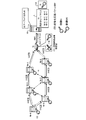
- FIG. 2 to 6 are explanatory diagrams showing examples of key update in the ad hoc network Ai.
- FIG. 2 shows a state (A) before the key update.
- the management server 101 stores the current key Ki for each gateway Gi in the key information DB 110.
- FIG. 2 shows that the gateway Gi (address) and the current key Ki are associated with each other in the key information DB 110. Further, the gateway Gi and the nodes Ni-1 to Gi-6 also hold the current key Ki.
- FIG. 3 shows a state (B) transitioned from the state (A) in FIG.
- the gateway Gi generates a new key KKi and transmits the new key KKi to the management server 101 via the network NW1.
- the management server 101 Upon receiving the new key KKi from the gateway Gi, the management server 101 designates the gateway Gi record in the key information DB 110 using the address of the gateway Gi that is the transmission source of the new key KKi as a clue. The management server 101 stores the new key KKi in the designated record. As a result, the gateway Gi (address) and the new key KKi are associated with each other. The current key Ki is deleted when the new key KKi is saved.
- the gateway Gi encrypts the update notification information of the current key Ki with the current key Ki. Then, the gateway Gi broadcasts the encrypted packet SPi to the ad hoc network Ai. When the encrypted packet SPi is broadcast from the gateway Gi, the encrypted packet SPi is distributed to the nodes Ni-1 to Ni-6.
- FIG. 4 shows a state (C) transitioned from the state (B) in FIG. In the state (C), (4) the nodes Ni-1 to Ni-6 decrypt the encrypted packet SPi with the current key Ki and confirm whether update notification information of the current key Ki is included.
- an encrypted response packet RP in which the node address of the own node is encrypted with the current key Ki is transmitted to the gateway Gi.
- the gateway Gi Upon receiving the encryption response packet RP from the nodes Ni-1 to Ni-6, the gateway Gi decrypts it with the current key Ki. Then, the node addresses of the nodes Ni-1 to Ni-6 obtained by decoding are transmitted to the management server 101.
- the management server 101 Upon receiving the node addresses of the nodes Ni-1 to Ni-6 from the gateway Gi, the management server 101 associates the gateway Gi that is the transmission source with the node addresses of the nodes Ni-1 to Ni-6. Create The table Ti is created for each gateway Gi. The table Ti is information temporarily created when updating to the new key KKi. Therefore, the management server 101 does not need to always hold the tables Ti for the number of gateways Gi. Further, the table Ti is created only for the gateway Gi that performs the update to the new key KKi. Therefore, the management server 101 can save memory.
- the gateway Gi erases the current key Ki after a lapse of a certain period after the broadcast of the encrypted packet SPi.
- the certain period can be arbitrarily set, for example, 1 hour. In this way, by limiting the remaining period of the current key Ki, an encrypted packet (not limited to the encrypted response packet RP) transmitted after a certain period of time cannot be decrypted with the current key Ki, and the gateway Gi Discarded.
- FIG. 5 shows a state (D) transitioned from the state (C) in FIG.
- the mobile terminal H is connected to the node Ni-3, and the node Ni-3 uses the mobile terminal H as a communication interface to communicate with the management server 101.
- FIG. 5 illustrates the node Ni-3, the other nodes Ni-1, Ni-2, Ni-4 to Ni-6 are similarly executed.
- the worker goes to the place where the node Ni-3 is installed and connects the node Ni-3 and the portable terminal H.
- the portable terminal H is a computer that can communicate with the management server 101. Communication between the portable terminal H and the management server 101 may be established before or after connection of the node Ni-3.
- the update request packet rp is a packet including the node address of the own node, that is, the node Ni-3 in this case.
- the communication between the portable terminal H and the management server 101 may use existing encrypted communication such as a public key cryptosystem.
- the management server 101 Upon receiving the update request packet rp from the node Ni-3, the management server 101 specifies the node address of the node Ni-3 from the update request packet rp. The management server 101 refers to the table Ti and determines whether the node address of the node Ni-3 specified from the update request packet rp is in the table Ti. When there is a node address of the node Ni-3 in the table Ti, the management server 101 refers to the key information DB 110 and extracts a new key KKi associated with the address of the gateway Gi in the table Ti.
- the management server 101 transmits the new key KKi extracted from the key information DB 110 to the node Ni-3 via the mobile terminal H.
- the communication between the portable terminal H and the management server 101 may use existing encrypted communication such as a public key cryptosystem.
- the node Ni-3 updates the current key Ki to the new key KKi received from the management server 101 via the portable terminal H. Thereafter, when the node Ni-3 transmits a packet, it is encrypted and transmitted with the new key KKi, and the received packet is decrypted with the new key KKi.
- FIG. 6 shows a state (E) transitioned from the state (D) in FIG.
- the state (E) shows the result of executing the processing shown in the state (D) of FIG. 5 for the other nodes Ni-1, Ni-2, Ni-4 to Ni-6.
- the new key KKi is distributed to the nodes Ni-1 to Ni-6. Further, the current key Ki is erased from the key information DB 110 and the new key KKi is left. Thereafter, the new key KKi becomes a valid current key Ki in the ad hoc network Ai. Further, the table Ti is erased. Therefore, the management server 101 can save memory.
- FIG. 7 is an explanatory diagram showing an example of the data structure of the encrypted packet SPi broadcast from the gateway Gi.
- the encrypted packet SPi includes a header part 710 and a payload part 720.
- a destination address, a source address, the number of hops, and a GW address are described.
- the payload portion 720 describes the encrypted data body (hatched portion in FIG. 7).
- the destination address is the destination address.
- the broadcast MAC address “00: 00: 00: 00: 00: 00” is described.
- the sending address is a sender address.
- the source address is rewritten by multi-pop communication.
- the MAC address of another node Ni different from the node Ni in the ad hoc network Ai is described.
- the number of hops is a remaining transfer count indicating how many times the encrypted packet SPi is transferred.
- the maximum number of hops of the encrypted packet SPi broadcast from the gateway Gi is set in advance.
- the hop count is decremented when the encrypted packet SPi is transferred, and the encrypted packet SPi with the hop count of “0” is discarded.
- the hop number “10” of the encrypted packet SP1 is described.
- GW address is the address of the gateway Gi.
- the MAC address “AA: AA: AA: AA: AA: AA” of the gateway Gi is described. Note that although the MAC address is used as an example of the destination address, the sending address, and the GW address here, an IP address or the like may be used.
- the payload part 720 is decrypted with the encryption key Ki.
- update notification information including a key update flag 721 and a time stamp 722 is stored.
- the key update flag is bit information indicating that the current key Ki (encryption key Ki) is updated. For example, by specifying the bit position of the key update flag in advance, it is possible to detect that the key is updated at each of the nodes Ni-1 to Ni-mi.
- the time stamp is information describing the generation time of the update notification information.
- the nodes Ni-1 to Ni-mi receive the encrypted packet SPi, they hold the latest one of the time stamps.
- each of the nodes Ni-1 to Ni-mi compares the held time stamp with the time stamp obtained by decrypting the currently received encrypted packet SPi. . If the time stamp obtained by decrypting the encrypted packet SPi received this time is new, it is assumed that the key update flag is valid, and each of the nodes Ni-1 to Ni-mi executes the key update process. It becomes.
- FIG. 8 is an explanatory diagram showing another example of the data structure of the encrypted packet SPi broadcast from the gateway Gi.
- the GW address of the gateway Gi that broadcasts the encrypted packet SPi is embedded in the header portion 710.
- the GW address of the gateway Gi is not embedded in the header portion 810. Instead, the GW address of the gateway Gi is embedded in the decrypted payload portion 820. In the case of the encrypted packet SPi shown in FIG. 8, the GW address of the broadcasted gateway Gi cannot be specified unless the encrypted packet SPi is decrypted with the encryption key Ki.
- FIG. 9 is an explanatory diagram showing an example of the data structure of the encrypted response packet RP transmitted from the node Ni to the gateway Gi.
- the encrypted response packet RP has a configuration including a header portion 910 and a payload portion 920.
- a header part 910 a destination address and a source address are described.
- the payload portion 920 describes the encrypted data body (hatched portion in FIG. 9).
- the destination address is the destination address.
- the MAC address “AA: AA: AA: AA: AA: AA: AA” which is the GW address of the gateway Gi is described.
- the sending address is a sender address.
- the source address is rewritten by multi-pop communication.
- the MAC address of another node Ni different from the node Ni in the ad hoc network Ai is described.
- the payload portion 920 is decrypted with the current key Ki.
- the decrypted payload portion 920 stores response notification information including the node address of the response node and a response notification flag.
- the response notification flag is bit information indicating that the update of the current key Ki (encryption key Ki) has been confirmed. For example, by designating the bit position of the response notification flag in advance, the gateway Gi can detect that the node Ni has responded to the encrypted packet SPi.
- FIG. 10 is a block diagram of a hardware configuration example of the management server 101 according to the embodiment.
- the management server 101 includes a CPU (Central Processing Unit) 1001, a ROM (Read Only Memory) 1002, a RAM (Random Access Memory) 1003, a magnetic disk drive 1004, a magnetic disk 1005, and an optical disk drive 1006.
- the CPU 1001 to the mouse 1011 are connected to each other by a bus 1000.
- the CPU 1001 governs overall control of the management server 101.
- the ROM 1002 stores a program such as a boot program.
- the RAM 1003 is used as a work area for the CPU 1001.
- the magnetic disk drive 1004 controls data read / write with respect to the magnetic disk 1005 under the control of the CPU 1001.
- the magnetic disk 1005 stores data written under the control of the magnetic disk drive 1004.
- the optical disc drive 1006 controls reading / writing of data with respect to the optical disc 1007 according to the control of the CPU 1001.
- the optical disc 1007 stores data written under the control of the optical disc drive 1006, and causes the computer to read data stored on the optical disc 1007.
- the I / F 1008 is connected to the networks NW1 and NW2 through communication lines, and is connected to other devices (for example, the gateway Gi and the portable terminal H) via the networks NW1 and NW2.
- the I / F 1008 serves as an internal interface with the networks NW1 and NW2 and controls data input / output from an external device.
- a modem or a LAN adapter can be employed as the I / F 1008.
- the display 1009 displays data such as a document, an image, and function information as well as a cursor, an icon, or a tool box.
- a CRT a CRT
- a TFT liquid crystal display a plasma display, or the like can be adopted.
- the keyboard 1010 includes keys for inputting characters, numbers, various instructions, etc., and inputs data. Moreover, a touch panel type input pad or a numeric keypad may be used.
- the mouse 1011 performs cursor movement, range selection, window movement, size change, and the like. A trackball or a joystick may be used as long as they have the same function as a pointing device. Note that the mobile terminal H shown in FIG. 2 can also be realized with the same hardware configuration as that of the management server 101 shown in FIG.
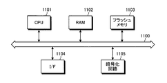
- FIG. 11 is a block diagram illustrating a hardware configuration example of the gateway Gi and the nodes Ni-1 to Ni-mi (hereinafter, “nodes”) according to the embodiment.
- the node or the like includes a CPU 1101, a RAM 1102, a flash memory 1103, an I / F 1104, and an encryption circuit 1105.
- the CPU 1101 to the encryption circuit 1105 are connected by a bus 1100, respectively.
- the CPU 1101 controls the entire node and the like.
- the RAM 1102 is used as a work area for the CPU 1101.
- the flash memory 1103 stores key information such as programs and encryption keys.
- the I / F 1104 transmits and receives packets by multi-hop communication. Further, the I / F 1104 of the gateway Gi is connected to the network NW1 through a communication line, and is connected to the management server 101 via the network NW1.
- the encryption circuit 1105 is a circuit that encrypts data using an encryption key when encrypting the data. When encryption is executed by software, the encryption circuit 1105 is not necessary by storing a program corresponding to the encryption circuit 1105 in the flash memory 1103.
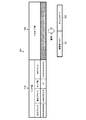
- FIG. 12 is an explanatory diagram showing an example of the contents stored in the key information DB 110.
- the key information DB 110 has fields of ID, GW address, and encryption key. By setting information in each field, the key information 1200-1 to 1200-n for each gateway G1 to Gn is used as a record. I remember it.
- the ID is an identifier of each gateway Gi used for explanation in this specification.
- the GW address is the address of the gateway Gi.
- the GW address for example, the MAC address or IP address of the gateway Gi can be used.
- the current key is a currently valid encryption key unique to each gateway Gi, and is specifically binary data of about 128 to 256 bits, for example.
- the new key KKi is an updated encryption key unique to each gateway Gi, and is specifically binary data of about 128 to 256 bits, for example.
- the new key KKi is stored in the key information DB 110 in the update process, and is stored in the key information DB 110 as the current key when the update process is completed.
- the gateway G1's GW address is “xx: xx: xx: xx: 12: 34”, and the encryption key is “encryption key K1”.
- the key information DB 110 is realized by a storage device such as the ROM 1002, the RAM 1003, the magnetic disk 1005, and the optical disk 1007 of the management server 101 shown in FIG.
- the content stored in the key information DB 110 may be updated when the management server 101 receives the encryption key Ki unique to the gateway Gi from the gateway Gi. Further, the stored content of the key information DB 110 may be updated by a user operation input using the keyboard 1010 or the mouse 1011 shown in FIG.
- FIG. 13 is an explanatory diagram showing an example of the contents stored in the table Ti.
- the table Ti has fields of ID and node address. By setting information in each field, the node addresses of the nodes Ni1-1 to Ni-6 in the ad hoc network Ai having the gateway Gi are set. It is memorized as a record.
- the symbol of the node Ni is shown as a node address.
- As the node address a MAC address or an IP address can be used.
- FIG. 14 is a block diagram illustrating a functional configuration example of the gateway Gi.
- the gateway Gi includes a distribution unit 1401, an acquisition unit 1402, and a transmission unit 1403.
- each functional unit (distribution unit 1401 to transmission unit 1403), for example, causes the CPU 1101 to execute a program stored in a storage device such as the RAM 1102 and the flash memory 1103 illustrated in FIG.
- the function is realized by the I / F 1104.
- the processing results of the respective functional units (distribution unit 1401 to transmission unit 1403) are stored in a storage device such as the RAM 1102 or the flash memory 1103, for example.
- the distribution unit 1401 simultaneously notifies the ad hoc network Ai of the encrypted packet SPi that has the GW address of the gateway Gi and the update notification information of the current key Ki, and at least the update notification information is encrypted with the current key Ki.
- the data structure of the encrypted packet SPi may be any of the data structures shown in FIG. 7 or FIG.
- the gateway Gi when the gateway Gi receives an update instruction for the current key Ki, the gateway Gi generates update notification information. Then, the gateway Gi generates an encrypted packet SPi using the generated update notification information as payload portions 720 and 820. The gateway Gi uses the distribution unit 1401 to broadcast the generated encrypted packet SPi to the ad hoc network Ai.
- the update instruction for the current key Ki may be an operation input to the gateway Gi or an automatic update instruction given periodically.
- an update instruction for the current key Ki may be received from the management server 101.
- the acquisition unit 1402 acquires a new key KKi unique to the gateway Gi.
- the acquisition unit 1402 includes a generation unit 1421 and a storage unit 1422, for example.
- the generation unit 1421 generates a new key KKi.
- the generation unit 1421 generates a new key KKi using a random number generation function.
- the storage unit 1422 stores the new key KKi generated by the generation unit 1421.
- the storage unit 1422 stores the new key KKi in a storage device such as the RAM 1102 and the flash memory 1103 in the gateway Gi. Further, since the current key Ki needs to decrypt the encrypted response packet RP from the node Ni, it is held for a certain period and then erased.
- the transmission unit 1403 transmits the new key KKi to the management server 101 via the network NW1. Thereafter, by completing the key update process between each of the nodes Ni-1 to Ni-mi and the management server 101, it is possible to communicate with the packet encrypted with the new key KKi within the ad hoc network Ai. Become.
- FIG. 15 is a block diagram illustrating a functional configuration example of the management server 101.
- the management server 101 includes a key information DB 110, an acquisition unit 1501, a creation unit 1502, a reception unit 1503, a determination unit 1504, an extraction unit 1505, and a transmission unit 1506.
- the key information DB 110 realizes its function by a storage device such as the ROM 1002, the RAM 1003, the magnetic disk 1005, and the optical disk 1007 shown in FIG.
- each of the functional units specifically stores, for example, a program stored in a storage device such as the ROM 1002, the RAM 1003, the magnetic disk 1005, and the optical disk 1007 shown in FIG.
- the function is realized by executing or by the I / F 1008.
- the processing results of the respective functional units are stored in a storage device such as the RAM 1003, the magnetic disk 1005, and the optical disk 1007, for example.
- the acquisition unit 1501 acquires the new key KKi, stores the new key KKi in the key information DB 110 in association with the current key Ki. Specifically, for example, the acquisition unit 1501 receives the new key KKi from the gateway Gi. The received new key KKi is stored in the new key field of the gateway Gi record of the key information DB 110 using the GW address of the gateway Gi stored as the transmission source in the header of the transmission packet of the new key KKi. .
- the creating unit 1502 creates information in which the gateway GW's GW address is associated with the node address of each node Ni. Specifically, for example, the creation unit 1502 creates the table Ti described above. The creation unit 1502 deletes the table Ti after the update to the new key KKi is completed. As described above, the table Ti is created only during the update, and is deleted after the update, so that the management server 101 can save memory.
- SSL Secure SocketTi Layer
- the determination unit 1504 determines whether or not the node address of a specific node Ni-x (for example, the node Ni-3) included in the update request packet rp is in the table Ti created by the creation unit 1502. . For example, in the example of FIG. 5, since the node address of the node Ni-3 exists in the table Ti, the determination unit 1504 determines that the node address of the node Ni-3 is in the table Ti. The determination unit 1504 may delete the node address determined to be in the table Ti from the table Ti.
- a specific node Ni-x for example, the node Ni-3 included in the update request packet rp
- the extraction unit 1505 extracts the current key Ki of the gateway Gi from the key information DB 110 based on the GW address of the gateway Gi. Specifically, for example, when the determination unit 1504 determines that there is a specific node Ni-x (for example, the node Ni-3) included in the update request packet rp, the extraction unit 1505 stores the table Ti The ID of the gateway Gi that is the creation target is specified from the key information DB 110. Then, the extraction unit 1505 extracts the new key KKi from the identified ID record.
- a specific node Ni-x for example, the node Ni-3
- the transmission unit 1506 transmits the new key KKi extracted by the extraction unit 1505 to the specific node Ni-x via the mobile terminal H.
- the new key KKi can be assigned to the specific node Ni-x without going through the ad hoc network Ai.
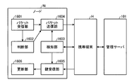
- FIG. 16 is a block diagram illustrating a functional configuration example of the node Ni.
- the node Ni includes a packet reception unit 1601, a determination unit 1602, a detection unit 1603, a packet transmission unit 1604, a key reception unit 1605, and an update unit 1606.
- each of the functional units causes the CPU 1101 to execute a program stored in a storage device such as the RAM 1102 and the flash memory 1103 illustrated in FIG.
- the function is realized by the I / F 1104.
- the processing results of the respective function units are stored in a storage device such as the RAM 1102 and the flash memory 1103 unless otherwise specified.
- the packet receiving unit 1601 receives the encrypted packet SPi broadcast from the gateway Gi in the ad hoc network Ai.
- the encrypted packet SPi is a packet encrypted using the encryption key Ki (current key Ki) unique to the gateway Gi.
- the encrypted packet SPi is, for example, a packet including update notification information that notifies the ad hoc network Ai of update processing.
- the packet receiving unit 1601 receives the encrypted packet SPi from another node Ni in the ad hoc network Ai by multihop communication. However, if the gateway Gi exists in the communication area of the node Ni, the packet receiving unit 1601 may directly receive the encrypted packet SPi from the gateway Gi.
- the determination unit 1602 determines whether each node Ni-1 to Ni-mi in the node group constituting the ad hoc network Ai has update notification information by decrypting the encrypted packet SPi with the current key Ki. To do. Specifically, for example, the node Ni determines whether or not a key update flag is set at a bit position designated in advance in a packet decrypted from the encrypted packet SPi. Further, the determination unit 1602 may determine whether or not the encrypted packet SPi received this time is the latest as compared with the time stamp of the update notification information stored last time.
- the determining unit 1602 may determine whether there is a GW address that is not encrypted with the current key Ki. Further, when the encrypted packet SPi has the data structure shown in FIG. 8, the determination unit 1602 also determines whether or not the update notification information obtained by decrypting the encrypted packet SPi with the current key Ki has a GW address. It is good. In this case, since the GW address cannot be specified unless decryption is possible, the update process can be performed securely if the current key Ki is not leaked.
- the detection unit 1603 detects a connection with the mobile terminal H that can communicate with the management server 101. Specifically, for example, as a result of the worker connecting the portable terminal H and the new node N using a USB cable, the detection unit 1603 detects the connection with the portable terminal H via the USB cable.
- the packet transmission unit 1604 transmits an encrypted response packet RP obtained by encrypting the node address of the own node with the current key Ki to the gateway Gi.
- the packet transmission unit 1604 may transmit the update request packet RP to the GW address.
- the packet transmission unit 1604 transmits an update request packet rp including the node address of the own node to the management server 101 via the mobile terminal H. Specifically, for example, the packet transmission unit 1604 transmits the update request packet rp to the mobile terminal H via the network NW3 such as a USB cable. As a result, the mobile terminal H transmits an update request packet rp from the node Ni to the management server 101 via the network NW2.
- the key receiving unit 1605 receives the encryption key KKi unique to the gateway Gi from the management server 101 via the mobile terminal H.
- the encryption key KKi is, for example, a common key that can encrypt a packet at the node Ni-x and decrypt the encrypted packet SPi encrypted using the encryption key KKi.
- the update unit 1606 updates the current key Ki to the new key KKi. Thereby, the encryption of the packet to be transmitted by the node Ni and the decryption of the encrypted packet SPi are executed with the new key KKi. Therefore, secure communication can be performed between nodes in the ad hoc network Ai.
- the update unit 1606 may update the new key KKi by overwriting the current key Ki, and the current key Ki may be updated until the node Ni transmits the encrypted packet SPi to the management server 101. It may be erased.
- the mobile terminal H receives the SSL server certificate from the management server 101.
- the received SSL server certificate is stored in a storage device such as the RAM 1102 or the flash memory 1103 of the mobile terminal H in association with the IP address of the management server 101, for example.
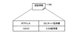
- FIG. 17 is an explanatory diagram showing an example of authentication information of the management server 101.
- the authentication information 1700 of the management server 101 has an IP address and an SSL server certificate.
- the IP address is the IP address of the management server 101.
- the 509 certificate is an SSL server certificate (public key certificate) of the management server 101.
- the mobile terminal H performs server authentication by decrypting the SSL server certificate using a public key incorporated in the terminal in advance.
- the public key is issued by, for example, a third-party certification body. If the SSL server certificate can be correctly decrypted using this public key, it can be seen that the SSL server certificate is a correct certificate certified by a third-party certification authority, and that the identity of the management server 101 has been guaranteed. Become.
- the authentication information 1800 is stored in a storage device such as the ROM 1002, the RAM 1003, the magnetic disk 1005, and the optical disk 1007 of the management server 101, for example.
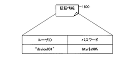
- FIG. 18 is an explanatory diagram showing an example of authentication information of the mobile terminal H.
- the authentication information 1800 of the mobile terminal H has a user ID and a password.
- the user ID is an identifier of the mobile terminal H.
- the password is for authenticating a user who uses the mobile terminal H.
- the mobile terminal H transmits a user ID and password pair to the management server 101.
- This user ID and password may be registered in advance in the flash memory 1103 of the mobile terminal H, or may be received by a user operation input using an input device (not shown) of the mobile terminal H.
- the management server 101 determines that the user ID and password pair from the portable terminal H matches the user ID and password pair of the authentication information 1800.
- the user ID and password of the authentication information 1800 match, the identity of the user of the portable terminal H is guaranteed.
- the mobile terminal H communicates with the management server 101 by encrypting the packet using, for example, a public key included in the SSL server certificate of the management server 101. Thereby, secure communication can be performed between the management server 101 and the portable terminal H.
- FIG. 19 is a sequence diagram illustrating a key update sequence example according to the embodiment.
- the gateway Gi generates a new key KKi unique to the gateway Gi (step S1901).
- the gateway Gi transmits the generated new key KKi and the GW address of the gateway Gi to the management server 101 (step S1902).
- the management server 101 secures a record of ID: i designating the gateway Gi, and stores the received new key KKi in the record of ID: i in the key information DB 110 in association with the GW address of the gateway Gi (step S1903).
- the gateway Gi generates update notification information (step S1904), and encrypts the update notification information with the current key Ki to generate an encrypted packet SPi (step S1905).
- the gateway Gi broadcasts the encrypted packet SPi within the ad hoc network Ai (step S1906). As a result, the encrypted packet SPi is distributed to the nodes Ni-1 to Ni-mi through multi-hop communication in the ad hoc network Ai.
- the nodes Ni-1 to Ni-mi execute key update pre-processing (step S1907). Details of the key update pre-processing (step S1907) will be described later with reference to FIG.
- the nodes Ni-1 to Ni-mi transmit the encryption response packet RP to the gateway Gi (step S1908). Then, the gateway Gi decrypts each transmitted encrypted packet RP with the current key Ki (step S1909). When the encrypted packet RP is decrypted, the node address of each transmission source is detected. The gateway Gi transmits the GW address of the gateway Gi and the node address group obtained by decryption to the management server 101 via the network NW1 (step S1910).
- the gateway Gi deletes the current key Ki when a certain period has elapsed after the broadcast of the encrypted packet SPi (step S1911). Thereby, the gateway Gi will now distribute the packet encrypted with the new key KKi to the ad hoc network Ai and decrypt the packet received from the ad hoc network Ai with the new key KKi. Packets that cannot be decrypted with the new key KKi are discarded.
- the management server 101 receives the GW address and node address group of the gateway Gi transmitted from the gateway Gi, and creates a table Ti (step S1912).
- the gateway Gi ID is specified from the key information DB 110 using the gateway GW address as a clue.
- the creation unit creates the table Ti by associating the identified ID with the received node address group.
- the nodes Ni-1 to Ni-mi determine the connection with the mobile terminal H after transmitting the encryption response packet RP (step S1913). In FIG. 19, it is assumed that the connection of the node Ni-3 with the mobile terminal H is detected.
- the node Ni-3 transmits the update request packet rp including the node address of the node Ni-3 to the management server 101 via the mobile terminal H (step S1914).
- the management server 101 executes a new key specifying process (step S1915). Details of the new key specifying process (step S1915) will be described later with reference to FIG.
- the management server 101 transmits the new key KKi specified in the new key specifying process (step S1915) to the node Ni-3 via the portable terminal H (step S1916).
- the node Ni-3 When the node Ni-3 receives the new key KKi from the management server 101 via the mobile terminal H, the node Ni-3 updates the key used in the ad hoc network Ai from the current key Ki to the new key KKi (step S1917).
- the worker can sequentially perform key update operations from arbitrarily selected nodes Ni without checking which node Ni in the ad hoc network Ai is how many hops away from the gateway Gi. Therefore, the efficiency of the key update work can be improved.
- FIG. 20 is a flowchart showing an example of a detailed processing procedure of the key update pre-processing (step S1907) shown in FIG.
- the node Ni decrypts the encrypted packet SPi broadcast from the gateway Gi with the current key Ki (step S2001).
- the node Ni determines whether or not the packet decrypted from the encrypted packet SPi is update notification information (step S2002). If it is not update notification information (step S2002: No), the key update pre-processing (step S1907) is terminated. In this case, the key update is not performed.
- step S2002 determines whether it is update notification information (step S2002: Yes).
- the node Ni generates an encrypted response packet RP using the current key Ki (step S2003).
- the node Ni writes the encrypted response packet RP in the transmission buffer in the node Ni.
- the pre-key update process (step S1907) is terminated, and the encrypted response packet RP is transmitted to the gateway Gi.
- FIG. 21 is a flowchart showing an example of a detailed processing procedure of the new key specifying process (step S1915) shown in FIG.
- the management server 101 detects a node address included in the update request packet rp (step S2101).
- the management server 101 determines whether or not the detected node address is registered in the table Ti (step S2102). If not registered in the table Ti (step S2102: No), the management server 101 executes an error process (step S2104) and ends the new key specifying process (step S1915).
- the extraction unit transmits an error message indicating that the new key KKi could not be extracted to the specific node Ni-x via the mobile terminal H. It may be.
- Error processing is executed, for example, when the encrypted packet SPi has been tampered with or when a part of the encrypted packet SPi has been lost. According to this error processing, it is possible to prompt the retransmission of the encrypted packet SPi by the specific node Ni-x.
- step S2102 if registered in the table Ti (step S2102: Yes), the management server 101 extracts a new key KKi unique to the gateway Gi from the key information DB 110 using the gateway Gi ID of the table Ti as a clue. (Step S2103).
- the management server 101 transmits the new key KKi specified in the new key specifying process (step S1915) to the node Ni-3 via the portable terminal H (step S1916).
- the new key KKi can be securely and efficiently given to the specific node Ni-x connected to the mobile terminal H via the mobile terminal H.
- the management server 101 may generate the new key KKi.
- the management server 101 executes the generation of the new key KKi, the processing load of each gateway Gi can be reduced. Further, since the generation of the new key KKi can be concentrated on a single computer called the management server 101, the cost of the gateways G1 to Gn can be reduced.
- the management server 101 generates a new key KKi will be described.
- FIG. 22 is a block diagram illustrating another example of the functional configuration of the gateway Gi.
- the same components as those shown in FIG. 14 are denoted by the same reference numerals, and the description thereof is omitted.
- the gateway Gi includes a distribution unit 1401 and an acquisition unit 2202.
- each function unit (distribution unit 1401 and acquisition unit 2202) causes the CPU 1101 to execute a program stored in a storage device such as the RAM 1102 and the flash memory 1103 illustrated in FIG.
- the function is realized by the I / F 1104.
- the processing results of the respective functional units are stored in a storage device such as the RAM 1102 or the flash memory 1103, for example.
- the acquisition unit 2202 acquires a new key KKi unique to the gateway Gi.
- the acquisition unit 2202 includes a reception unit 2221 and a storage unit 2222, for example.
- the receiving unit 2221 receives the new key KKi from the management server 101.
- the storage unit 2222 stores the new key KKi received by the reception unit 2221.
- the storage unit 2222 stores the new key KKi in a storage device such as the RAM 1102 or the flash memory 1103 in the gateway Gi. Since the current key Ki needs to decrypt the encrypted response packet RP from the node Ni, it is held for a certain period and then erased.
- FIG. 23 is a block diagram illustrating another example of the functional configuration of the management server 101.
- the same components as those shown in FIG. 15 are denoted by the same reference numerals, and the description thereof is omitted.
- the management server 101 includes a key information DB 110, an acquisition unit 2300, a first transmission unit 2301, a creation unit 1502, a reception unit 1503, a determination unit 1504, an extraction unit 1505, and a second transmission unit 2302. It is equipped with.
- each of the functional units executes a program stored in a storage device such as the ROM 1002, the RAM 1003, the magnetic disk 1005, and the optical disk 1007 shown in FIG.
- the function is realized by executing the function or by the I / F 1008.
- the processing results of the respective function units are stored in a storage device such as the RAM 1003, the magnetic disk 1005, and the optical disk 1007, for example.
- the acquiring unit 2300 acquires the new key KKi and stores the new key KKi in the key information DB 110 in association with the GW address of the gateway Gi.
- the acquisition unit 2300 includes, for example, a generation unit 2311 and a storage unit 2312.
- the generation unit 2311 generates a new key KKi for the gateway Gi to be updated. For example, the generation unit 2311 generates a new key KKi using a random number generation function.
- the storage unit 2312 stores the new key KKi generated by the generation unit 2311. For example, the storage unit 2312 stores the new key KKi in the key information DB 110 in association with the GW address of the gateway Gi.
- the first transmission unit 2301 transmits the new key KKi unique to the gateway Gi generated by the generation unit 2311 of the management server 101 to the gateway Gi.
- the transmitted new key KKi is stored in the gateway Gi.
- the second transmission unit 2302 transmits the new key KKi extracted by the extraction unit 1505 to the specific node Ni-x via the mobile terminal H.
- the new key KKi can be assigned to the specific node Ni-x without going through the ad hoc network Ai.
- FIG. 24 is a sequence diagram illustrating another example of the key update sequence according to the embodiment.
- symbol is attached
- the management server 101 generates a new key KKi unique to the gateway Gi (step S2401). Then, the management server 101 transmits the generated new key KKi to the gateway Gi via the network NW1 (step S2402).
- the gateway Gi When the gateway Gi receives the new key KKi from the management server 101 in step S2402, the gateway Gi generates update notification information (step S1904). Further, when generating the new key KKi, the management server 101 stores the new key KKi in the key information DB 110 in association with the GW address of the gateway Gi (step S2403).
- the worker can arbitrarily determine which node Ni in the ad hoc network Ai is how many hops away from the gateway Gi.
- the key update operation can be sequentially performed from the node Ni selected in the above. Therefore, the efficiency of the key update work can be improved.
- the node Ni can acquire the new key KKi from the networks NW2 and NW3 other than the ad hoc network Ai in exchange for the node address. There is no need to exhaustively search which node Ni is how many hops away from the gateway Gi. Therefore, it is possible to reduce the burden of the key update work by the worker. Further, even if the current key Ki is leaked, the key update operation is efficiently performed. Therefore, the encrypted communication in the ad hoc network Ai can be recovered early by updating to the new key KKi.
- the key update method described in the present embodiment can be realized by executing a program prepared in advance on a computer such as a personal computer or a workstation.
- the key setting program is recorded on a computer-readable recording medium such as a hard disk, a flexible disk, a CD-ROM, an MO, and a DVD, and is executed by being read from the recording medium by the computer.
- Management server 110 Key information DB Ai Ad hoc network Gi Gateway H Mobile terminal Ki Current key (encryption key) KKi new key (encryption key) Ni node SPi encrypted packet RP encrypted response packet rp update request packet Ti table
Abstract
作業員は、ノード(Ni-3)の設置場所に行き、ノード(Ni-3)と携帯端末(H)とを接続する。ノード(Ni-3)は、更新要求パケット(rp)を管理サーバ(101)に送信する。管理サーバ(101)は、更新要求パケット(rp)をノード(Ni-3)から受信すると、更新要求パケット(rp)からノード(Ni-3)のアドレスを特定する。ノード(Ni-3)のアドレスが更新要求パケット(rp)から特定されるため、管理サーバ(101)は、テーブル(Ti)を参照して、ゲートウェイ(Gi)を特定する。そして、管理サーバ(101)は、鍵情報DB(110)を参照して、ゲートウェイ(Gi)固有の新鍵(KKi)を抽出する。管理サーバ(101)は、鍵情報DB(110)から抽出された新鍵(KKi)を、携帯端末(H)を介してノード(Ni-3)に送信する。
Description
本発明は、データを暗号化するための鍵を更新する鍵更新方法、ノード、ゲートウェイ、サーバ、およびネットワークシステムに関する。
アドホックネットワークは、無線通信でリンクする自己構成型のネットワークの一種である。アドホックネットワークは複数のノードにより構成される。また、アドホックネットワーク内の各ノードは、マルチホップ通信によりパケットの送受信を行う。マルチホップ通信は、互いの通信圏内に存在しないノード同士が、各ノードの通信圏内に存在する別のノードを介して通信を行う技術である。
また、アドホックネットワークとインターネット、LAN(Local Area Network)、WAN(Wide Area Network)などの他のネットワークとを接続する場合、ゲートウェイと呼ばれる中継機器を用いて、ネットワーク間の通信の転送が行われる。
アドホックネットワークを利用した技術として、各家庭の電力メータに無線通信可能なノードを組み込んで、作業員が現地に出向くことなく、アドホックネットワーク経由でメータ確認などの業務を行うシステムがある。各家庭の電力の使用量などの個人情報を扱うアドホックネットワークでは、秘匿性や改ざん防止の観点からセキュアな通信を行うことが要求される。
そこで、従来のシステムでは、アドホックネットワーク内のノード間で送受信されるパケットを暗号化することで、セキュアな通信を確保することが行われている。この際、システム内の全ノードで共通の暗号鍵を用いた場合、鍵漏洩時のリスクが大きいため、ゲートウェイごとに暗号鍵を変えるシステムがある。
また、システムへの新規ノードの初期導入時などにおいて、新規ノードは、暗号鍵が設定されるまでの間、アドホックネットワーク内の他のノードとセキュアな通信を行うことができない。このため、アドホックネットワーク経由で新規ノードに暗号鍵を自動設定することが難しく、作業員が現地に出向いて暗号鍵の設定作業を行っている。
また、セキュア通信に関する先行技術として、たとえば、ブロードキャストにより通信を行うネットワークの暗号鍵を管理する技術がある(たとえば、下記特許文献1参照。)。また、アドホックネットワークにおいて通信開始時の鍵交換を安定して行うための技術がある(たとえば、下記特許文献2参照。)。また、アドホックネットワーク内の各ノードが適応ゲートウェイを選択するための技術がある(たとえば、下記特許文献3参照。)。また、異なるネットワーク間に所属する複数のデバイスに鍵を渡し、それを用いてアドホックネットワークを構成する技術がある(たとえば、下記特許文献4参照。)。
しかしながら、上述した従来技術では、アドホックネットワーク内の各ノードに設定する暗号鍵をゲートウェイごとに更新する場合、ノードが属するゲートウェイを特定することが難しいという問題があった。
たとえば、ノードの設置場所の住所から候補となるゲートウェイを絞り込むことはできても、天候や近傍の建物との位置関係などの要因により通信状況が変化する。このため、実際にどのゲートウェイと通信可能であるかを作業員が現地に出向いて確認する必要があり、作業員の暗号鍵の更新作業にかかる作業時間および作業負荷の増大を招くという問題がある。
また、ゲートウェイが暗号鍵を更新したタイミングで暗号鍵を更新できるのはゲートウェイから1ホップ隣のノードのみである。具体的には、1ホップ隣のノードがゲートウェイからのブロードキャストパケット(以下、「BCパケット」)を受信することはできるが、BCパケットは新しい暗号鍵(以下、「新鍵」)で暗号化されている。したがって、当該パケットは現在所有している暗号鍵(以下、「現鍵」)で復号することができず、ゲートウェイから2ホップ隣まで転送されないからである。
すなわち、アドホックネットワークでの鍵更新の開始直後には、ゲートウェイから1ホップ隣のノードは新鍵に設定できるが、ゲートウェイから2ホップ先のノード以降は鍵設定することができない。換言すれば、ゲートウェイから2ホップ隣のノードは、ゲートウェイから1ホップ隣のノードについて鍵更新が完了し、ゲートウェイからのBCパケットを受信可能となって初めて鍵更新が可能となる。
しかしながら、どのノードがゲートウェイから何ホップ先であるかを調査するのは非常に困難である。また、ノードの設置時に何ホップ先であるかを記録していても、上述したように、各種要因により通信状況が変化する。したがって、結局、実際にどのノードがゲートウェイから何ホップ先であるかを、作業員が現地に出向いてその都度確認する必要がある。このように、従来では、作業員の暗号鍵の更新作業にかかる作業時間および作業負荷の増大を招くという問題がある。
本発明は、上述した従来技術による問題点を解消するため、アドホックネットワーク内のノードが用いる暗号鍵の更新作業の効率化を図ることができる鍵更新方法、ノード、ゲートウェイ、サーバ、およびネットワークシステムを提供することを目的とする。
上述した課題を解決し、目的を達成するため、アドホックネットワーク内のゲートウェイと、前記アドホックネットワーク内のノード群と、前記ゲートウェイと通信可能なサーバと、を備え、前記ノード群の各ノードに付与された前記ゲートウェイ固有の現鍵を更新するにあたって、前記ゲートウェイが、前記現鍵の更新通知情報を前記現鍵で暗号化した暗号化パケットを、前記アドホックネットワークに同時通報し、前記ゲートウェイが、前記ゲートウェイ固有の新鍵を取得して保存し、前記サーバが、前記新鍵を取得して、前記ゲートウェイのアドレスおよび前記現鍵を関連付けて保存するデータベースにおいて、前記ゲートウェイのアドレスに関連付けて前記新鍵を保存し、前記サーバが、前記アドホックネットワークを構成するノード群の各ノードのアドレスを、前記ゲートウェイから受信した場合、前記ゲートウェイのアドレスと前記各ノードのアドレスとを関連付けた情報を作成し、前記ノード群内の各ノードが、前記暗号化パケットを前記現鍵で復号することにより、前記更新通知情報であるか否かを判断し、前記ノード群内の前記サーバと通信可能な携帯端末と接続された特定のノードが、前記更新通知情報であると判断された場合、前記特定のノードのアドレスを含む更新要求パケットを、前記携帯端末を介して前記サーバに送信し、前記サーバが、前記データベースにおいて送信された更新要求パケットに含まれている前記特定のノードのアドレスが、作成された情報にあるか否かを判定し、前記サーバが、あると判定された場合、前記ゲートウェイのアドレスに関連付けられている前記新鍵を、前記データベースから抽出し、前記サーバが、抽出された前記新鍵を、前記携帯端末を介して前記特定のノードに送信し、前記特定のノードが、前記現鍵から、送信された前記新鍵に更新する鍵更新方法、ノード、ゲートウェイ、サーバ、およびネットワークシステムが一例として挙げられる。
本発明にかかる鍵更新方法、ノード、ゲートウェイ、サーバ、およびネットワークシステムによれば、アドホックネットワーク内のノードが用いる暗号鍵の更新作業の効率化を図ることができるという効果を奏する。
以下に添付図面を参照して、この発明にかかる鍵更新方法、ノード、ゲートウェイ、サーバ、およびネットワークシステムの実施の形態を詳細に説明する。
(ネットワークシステムの一実施例)
図1は、実施の形態にかかるネットワークシステムの一実施例を示す説明図である。図1において、ネットワークシステム100は、管理サーバ101と、ゲートウェイG1~Gnと、ノードN1-1~N1-m1,N2-1~N2-m2,…,Nn-1~Nn-mnと、を含む構成である。
図1は、実施の形態にかかるネットワークシステムの一実施例を示す説明図である。図1において、ネットワークシステム100は、管理サーバ101と、ゲートウェイG1~Gnと、ノードN1-1~N1-m1,N2-1~N2-m2,…,Nn-1~Nn-mnと、を含む構成である。
ネットワークシステム100において、管理サーバ101とゲートウェイG1~Gnは、インターネット、LAN、WANなどのネットワークNW1を介して相互に通信可能に接続されている。また、ゲートウェイGiとノードNi-1~Ni-miは、アドホックネットワークAiを介して接続されている(i=1,2,…,n)。なお、以降の説明で、単に「ノードNi」と表記した場合は、任意のアドホックネットワークAiを構成するノードNi-1~Ni-miの中の任意のノードを示すこととする。
ここで、管理サーバ101は、鍵情報DB(データベース)110を備え、各ゲートウェイG1~Gn固有の暗号鍵を管理するコンピュータである。ゲートウェイGi固有の暗号鍵(以下、「暗号鍵Ki」という)は、ゲートウェイGiが属するアドホックネットワークAi内のノード間で送受信されるパケットを暗号化するための鍵情報である。なお、鍵情報DB110についての詳細な説明は、図12を用いて後述する。
ゲートウェイGiは、アドホックネットワークAiとネットワークNW1とを接続する中継機器である。ゲートウェイGiは、アドホックネットワークAiのプロトコルとネットワークNW1のプロトコルの両方を理解し、アドホックネットワークAiとネットワークNW1との間の通信の転送を行う。
ノードNi-1~Ni-miは、所定の通信圏内の他ノードとマルチホップ通信を行う無線通信装置である。アドホックネットワークAiでは、すべてのノードNi-1~Ni-miがゲートウェイGiと直接通信できる必要はなく、一部のノードがゲートウェイGiと通信可能であればよい。
ネットワークシステム100は、たとえば、各家庭の電力やガスの使用量を収集するシステムに適用することができる。具体的には、たとえば、各家庭の電力メータやガスメータに各ノードNi-1~Ni-miを組み込むことで、アドホックネットワークAi内のノード間で各家庭の電力やガスの使用量を送受信する。なお、各家庭の電力やガスの使用量は、各ノードNi-1~Ni-miが計測してもよく、また、各ノードNi-1~Ni-miが電力メータやガスメータから取得してもよい。
ゲートウェイGiは、アドホックネットワークAi内のノードNi-1~Ni-miから受信した各家庭の電力やガスの使用量を、ネットワークNW1を介して電力会社やガス会社のサーバ(たとえば、管理サーバ101)に送信する。これにより、作業員が現地に出向くことなく電力やガスの使用量を収集することができる。
また、ネットワークシステム100では、アドホックネットワークAiごとにゲートウェイGi固有の暗号鍵Kiを用いてパケットを暗号化する。これにより、アドホックネットワークAiのセキュア通信(データ秘匿性、改ざん防止など)を確保する。また、アドホックネットワークAiごとに暗号鍵Kiを変えることで、鍵漏洩時のリスクを低減させる。また、受信されるパケットも暗号鍵Kiで暗号化されているため、ゲートウェイGiやその配下のノードNi-1~Ni-miは、暗号鍵Kiで復号することができる。
なお、図1の例では、アドホックネットワークAi内に1台のゲートウェイGiを設ける構成としたが、同一のアドホックネットワークAi内に複数台のゲートウェイGiを設ける構成としてもよい。この場合、アドホックネットワークAi内で送受信されるパケットを暗号化するための暗号鍵Kiは、複数台のゲートウェイGiで共通である。
(現鍵Kiの更新例)
暗号鍵Kiは、アドホックネットワークAi内のゲートウェイGiおよびノードNi-1~Ni-miで共通に使用される鍵情報である。以下では、アドホックネットワークAiで暗号鍵Kiを現在利用されている現鍵Kiとし、現鍵Kiを新鍵KKiに更新する例について説明する。
暗号鍵Kiは、アドホックネットワークAi内のゲートウェイGiおよびノードNi-1~Ni-miで共通に使用される鍵情報である。以下では、アドホックネットワークAiで暗号鍵Kiを現在利用されている現鍵Kiとし、現鍵Kiを新鍵KKiに更新する例について説明する。
図2~図6は、アドホックネットワークAiにおける鍵更新例を示す説明図である。図2は、鍵更新前の状態(A)を示している。管理サーバ101は、鍵情報DB110においてゲートウェイGiごとに現鍵Kiを保存している。図2では、鍵情報DB110において、ゲートウェイGi(のアドレス)と現鍵Kiとが関連付けられていることを示している。また、ゲートウェイGiおよびノードNi-1~Gi-6も現鍵Kiを保持している。
図3は、図2の状態(A)から遷移した状態(B)を示している。状態(B)では、(1)ゲートウェイGiは、新鍵KKiを生成し、ネットワークNW1を介して管理サーバ101に新鍵KKiを送信する。
(2)管理サーバ101は、ゲートウェイGiから新鍵KKiを受信すると、新鍵KKiの送信元であるゲートウェイGiのアドレスを手がかりとして、鍵情報DB110のゲートウェイGiのレコードを指定する。管理サーバ101は、指定したレコードに新鍵KKiを保存する。これにより、ゲートウェイGi(のアドレス)と新鍵KKiとが関連付けられる。現鍵Kiは、新鍵KKiが保存されると消去される。
(3)ゲートウェイGiは、現鍵Kiで現鍵Kiの更新通知情報を暗号化する。そして、ゲートウェイGiは、暗号化パケットSPiをアドホックネットワークAiに対しブロードキャストする。ゲートウェイGiから暗号化パケットSPiがブロードキャストされると、各ノードNi-1~Ni-6に暗号化パケットSPiが行き渡る。
図4は、図3の状態(B)から遷移した状態(C)を示している。状態(C)では、(4)ノードNi-1~Ni-6は暗号化パケットSPiを現鍵Kiで復号し、現鍵Kiの更新通知情報が含まれているかを確認する。更新通知情報が含まれている場合は、自ノードのノードアドレスを現鍵Kiで暗号化した暗号化応答パケットRPをゲートウェイGi宛に送信する。
(5)ゲートウェイGiは、ノードNi-1~Ni-6から暗号化応答パケットRPを受信すると、現鍵Kiで復号する。そして、復号で得られたノードNi-1~Ni-6のノードアドレスを管理サーバ101に送信する。
(6)管理サーバ101は、ゲートウェイGiからノードNi-1~Ni-6のノードアドレスを受信すると、送信元であるゲートウェイGiとノードNi-1~Ni-6のノードアドレスとを関連付けたテーブルTiを作成する。テーブルTiは、ゲートウェイGiごとに作成される。テーブルTiは、新鍵KKiへの更新時に一時的に作成される情報である。したがって、管理サーバ101は、ゲートウェイGiの台数分のテーブルTiを常時保持しておく必要がない。また、新鍵KKiへの更新をおこなうゲートウェイGiについてのみテーブルTiを作成する。したがって、管理サーバ101において省メモリ化を図ることができる。
(7)ゲートウェイGiは、暗号化パケットSPiのブロードキャスト後、一定期間経過後に現鍵Kiを消去する。一定期間は、たとえば、1時間など任意に設定することができる。このように、現鍵Kiの残存期間を制限することで、一定期間経過後に送信されてきた暗号化パケット(暗号化応答パケットRPに限られない)は現鍵Kiで復号できなくなり、ゲートウェイGiで破棄される。
図5は、図4の状態(C)から遷移した状態(D)を示している。状態(D)では、ノードNi-3に携帯端末Hを接続し、ノードNi-3が携帯端末Hを通信インターフェースとして利用して、管理サーバ101と通信をおこなう例を示している。図5では、ノードNi-3について説明しているが、他のノードNi-1,Ni-2,Ni-4~Ni-6も同様に実行する。
(8)作業員は、ノードNi-3の設置場所に行き、ノードNi-3と携帯端末Hとを接続する。携帯端末Hは、管理サーバ101と通信可能なコンピュータである。携帯端末Hと管理サーバ101との通信の確立は、ノードNi-3の接続前でも接続後でもよい。
(9)ノードNi-3と携帯端末Hとが接続されると、ノードNi-3は、更新要求パケットrpを管理サーバ101に送信する。更新要求パケットrpとは、自ノード、すなわち、ここでは、ノードNi-3のノードアドレスを含むパケットである。なお、携帯端末Hと管理サーバ101間の通信は、公開鍵暗号方式などの既存の暗号化通信を利用してもよい。
(10)管理サーバ101は、更新要求パケットrpをノードNi-3から受信すると、更新要求パケットrpからノードNi-3のノードアドレスを特定する。管理サーバ101は、テーブルTiを参照して、更新要求パケットrpから特定されたノードNi-3のノードアドレスが、テーブルTiにあるか否かを判定する。テーブルTiにノードNi-3のノードアドレスがある場合、管理サーバ101は、鍵情報DB110を参照して、テーブルTiでのゲートウェイGiのアドレスに関連付けられている新鍵KKiを抽出する。
(11)そして、管理サーバ101は、鍵情報DB110から抽出された新鍵KKiを、携帯端末Hを介してノードNi-3に送信する。なお、携帯端末Hと管理サーバ101間の通信は、公開鍵暗号方式などの既存の暗号化通信を利用してもよい。
(12)このあと、ノードNi-3は、現鍵Kiから、管理サーバ101から携帯端末Hを介して受信された新鍵KKiに更新する。これ以降、ノードNi-3がパケットを送信する場合は、新鍵KKiで暗号化して送信し、受信されたパケットについては新鍵KKiで復号することとなる。
図6は、図5の状態(D)から遷移した状態(E)を示している。状態(E)では、図5の状態(D)で示した処理を、他のノードNi-1,Ni-2,Ni-4~Ni-6についても実行した結果を示している。状態(E)では、各ノードNi-1~Ni-6に新鍵KKiが行き渡っている。また、鍵情報DB110から現鍵Kiが消去され新鍵KKiが残されている。このあと、新鍵KKiがアドホックネットワークAiでの有効な現鍵Kiとなる。また、テーブルTiは消去される。したがって、管理サーバ101において省メモリ化を図ることができる。
(暗号化パケットSPiのデータ構造例)
つぎに、ゲートウェイGiからブロードキャストされる暗号化パケットSPiのデータ構造例について説明する。
つぎに、ゲートウェイGiからブロードキャストされる暗号化パケットSPiのデータ構造例について説明する。
図7は、ゲートウェイGiからブロードキャストされる暗号化パケットSPiのデータ構造の一例を示す説明図である。図7において、暗号化パケットSPiは、ヘッダ部710とペイロード部720とを含む構成である。ヘッダ部710には、宛先アドレス、差出アドレス、ホップ数およびGWアドレスが記述されている。ペイロード部720には、暗号化されたデータ本体が記述されている(図7中ハッチ部分)。
ここで、宛先アドレスは、送信先のアドレスである。ここでは、ブロードキャスト用のMACアドレス『00:00:00:00:00:00』が記述されている。差出アドレスは、送信元のアドレスである。差出アドレスは、マルチポップ通信により書き換わる。ここでは、アドホックネットワークAi内のノードNiとは異なる他のノードNiのMACアドレスが記述されている。
ホップ数は、暗号化パケットSPiを残り何回転送するのかを示す残余の転送回数である。ゲートウェイGiからブロードキャストされる暗号化パケットSPiのホップ数の最大値は予め設定されている。ホップ数は暗号化パケットSPiの転送時にデクリメントされ、ホップ数が『0』となった暗号化パケットSPiは棄却される。ここでは、暗号化パケットSP1のホップ数『10』が記述されている。
GWアドレスは、ゲートウェイGiのアドレスである。ここでは、ゲートウェイGiのMACアドレス『AA:AA:AA:AA:AA:AA』が記述されている。なお、ここでは宛先アドレス、差出アドレスおよびGWアドレスの一例として、MACアドレスを用いて説明したが、IPアドレスなどのアドレスを用いることにしてもよい。
ペイロード部720は、暗号鍵Kiで復号される。復号されたペイロード部720には、鍵更新フラグ721とタイムスタンプ722を含む更新通知情報が記憶されている。鍵更新フラグとは、現鍵Ki(暗号鍵Ki)の更新をおこなうことを示すビット情報である。たとえば、鍵更新フラグのビット位置をあらかじめ指定しておくことで、各ノードNi-1~Ni-miで鍵の更新をおこなうことが検出できる。
また、タイムスタンプは、更新通知情報の生成時刻を記述した情報である。各ノードNi-1~Ni-miは、暗号化パケットSPiを受信する都度、そのタイムスタンプのうち最新のものを保持しておく。あらたに暗号化パケットSPiを受信したときは、各ノードNi-1~Ni-miは、保持されているタイムスタンプと今回受信した暗号化パケットSPiを復号して得られたタイムスタンプとを比較する。そして、今回受信した暗号化パケットSPiを復号して得られたタイムスタンプが新しければ、鍵更新フラグは有効であるとして、各ノードNi-1~Ni-miは、鍵更新処理を実行することとなる。
図8は、ゲートウェイGiからブロードキャストされる暗号化パケットSPiのデータ構造の他の例を示す説明図である。図7に示した暗号化パケットSPiでは、暗号化パケットSPiをブロードキャストしたゲートウェイGiのGWアドレスがヘッダ部710に埋め込まれていた。
これに対し、図8に示す暗号化パケットSPiでは、ヘッダ部810には、ゲートウェイGiのGWアドレスが埋め込まれていない。そのかわりに、復号されたペイロード部820に、ゲートウェイGiのGWアドレスが埋め込まれている。図8に示した暗号化パケットSPiの場合は、暗号化パケットSPiを暗号鍵Kiで復号しなければ、ブロードキャストしたゲートウェイGiのGWアドレスを特定することができない。
図9は、ノードNiからゲートウェイGi宛に送信される暗号化応答パケットRPのデータ構造の一例を示す説明図である。図9において、暗号化応答パケットRPは、ヘッダ部910とペイロード部920とを含む構成である。ヘッダ部910には、宛先アドレスおよび差出アドレスが記述されている。ペイロード部920には、暗号化されたデータ本体が記述されている(図9中ハッチ部分)。
ここで、宛先アドレスは、送信先のアドレスである。ここでは、ゲートウェイGiのGWアドレスであるMACアドレス『AA:AA:AA:AA:AA:AA』が記述されている。なお、ここでは宛先アドレス、差出アドレスおよびGWアドレスの一例として、MACアドレスを用いて説明したが、IPアドレスなどのアドレスを用いることにしてもよい。差出アドレスは、送信元のアドレスである。差出アドレスは、マルチポップ通信により書き換わる。ここでは、アドホックネットワークAi内のノードNiとは異なる他のノードNiのMACアドレスが記述されている。
ペイロード部920は、現鍵Kiで復号される。復号されたペイロード部920には、応答ノードのノードアドレスと応答通知フラグを含む応答通知情報が記憶されている。応答通知フラグとは、現鍵Ki(暗号鍵Ki)の更新を確認したことを示すビット情報である。たとえば、応答通知フラグのビット位置をあらかじめ指定しておくことで、ゲートウェイGiは、ノードNiが暗号化パケットSPiに応答したことを検出できる。
(管理サーバ101のハードウェア構成)
図10は、実施の形態にかかる管理サーバ101のハードウェア構成例を示すブロック図である。図10において、管理サーバ101は、CPU(Central Processing Unit)1001と、ROM(Read Only Memory)1002と、RAM(Random Access Memory)1003と、磁気ディスクドライブ1004と、磁気ディスク1005と、光ディスクドライブ1006と、光ディスク1007と、I/F(Interface)1008と、ディスプレイ1009と、キーボード1010と、マウス1011と、を備えている。また、CPU1001~マウス1011はバス1000によってそれぞれ接続されている。
図10は、実施の形態にかかる管理サーバ101のハードウェア構成例を示すブロック図である。図10において、管理サーバ101は、CPU(Central Processing Unit)1001と、ROM(Read Only Memory)1002と、RAM(Random Access Memory)1003と、磁気ディスクドライブ1004と、磁気ディスク1005と、光ディスクドライブ1006と、光ディスク1007と、I/F(Interface)1008と、ディスプレイ1009と、キーボード1010と、マウス1011と、を備えている。また、CPU1001~マウス1011はバス1000によってそれぞれ接続されている。
ここで、CPU1001は、管理サーバ101の全体の制御を司る。ROM1002は、ブートプログラムなどのプログラムを記憶している。RAM1003は、CPU1001のワークエリアとして使用される。磁気ディスクドライブ1004は、CPU1001の制御に従って磁気ディスク1005に対するデータのリード/ライトを制御する。磁気ディスク1005は、磁気ディスクドライブ1004の制御で書き込まれたデータを記憶する。
光ディスクドライブ1006は、CPU1001の制御に従って光ディスク1007に対するデータのリード/ライトを制御する。光ディスク1007は、光ディスクドライブ1006の制御で書き込まれたデータを記憶したり、光ディスク1007に記憶されたデータをコンピュータに読み取らせたりする。
I/F1008は、通信回線を通じてネットワークNW1,NW2に接続され、このネットワークNW1,NW2を介して他の装置(たとえば、ゲートウェイGi、携帯端末H)に接続される。I/F1008は、ネットワークNW1,NW2と内部のインターフェースを司り、外部装置からのデータの入出力を制御する。I/F1008には、たとえば、モデムやLANアダプタなどを採用することができる。
ディスプレイ1009は、カーソル、アイコンあるいはツールボックスをはじめ、文書、画像、機能情報などのデータを表示する。このディスプレイ1009は、たとえば、CRT、TFT液晶ディスプレイ、プラズマディスプレイなどを採用することができる。
キーボード1010は、文字、数字、各種指示などの入力のためのキーを備え、データの入力を行う。また、タッチパネル式の入力パッドやテンキーなどであってもよい。マウス1011は、カーソルの移動や範囲選択、あるいはウィンドウの移動やサイズの変更などを行う。ポインティングデバイスとして同様に機能を備えるものであれば、トラックボールやジョイスティックなどであってもよい。なお、図2に示した携帯端末Hについても、図10に示した管理サーバ101と同様のハードウェア構成により実現できる。
(ゲートウェイGiおよびノードNiのハードウェア構成)
図11は、実施の形態にかかるゲートウェイGiおよびノードNi-1~Ni-mi(以下、「ノード等」)のハードウェア構成例を示すブロック図である。図11において、ノード等は、CPU1101と、RAM1102と、フラッシュメモリ1103と、I/F1104と、暗号化回路1105と、を備えている。CPU1101~暗号化回路1105は、バス1100によってそれぞれ接続されている。
図11は、実施の形態にかかるゲートウェイGiおよびノードNi-1~Ni-mi(以下、「ノード等」)のハードウェア構成例を示すブロック図である。図11において、ノード等は、CPU1101と、RAM1102と、フラッシュメモリ1103と、I/F1104と、暗号化回路1105と、を備えている。CPU1101~暗号化回路1105は、バス1100によってそれぞれ接続されている。
ここで、CPU1101は、ノード等の全体の制御を司る。RAM1102は、CPU1101のワークエリアとして使用される。フラッシュメモリ1103は、プログラムや暗号鍵などの鍵情報を記憶している。I/F1104は、マルチホップ通信によりパケットを送受信する。また、ゲートウェイGiのI/F1104は、通信回線を通じてネットワークNW1に接続され、このネットワークNW1を介して管理サーバ101に接続される。
暗号化回路1105は、データを暗号化する場合に暗号鍵によりデータを暗号化する回路である。暗号化をソフトウェア的に実行する場合は、暗号化回路1105に相当するプログラムをフラッシュメモリ1103に記憶させておくことで、暗号化回路1105は不要となる。
(鍵情報DB110の記憶内容)
図12は、鍵情報DB110の記憶内容の一例を示す説明図である。図12において、鍵情報DB110は、ID、GWアドレス、暗号鍵のフィールドを有し、各フィールドに情報を設定することで、ゲートウェイG1~Gnごとの鍵情報1200-1~1200-nをレコードとして記憶している。
図12は、鍵情報DB110の記憶内容の一例を示す説明図である。図12において、鍵情報DB110は、ID、GWアドレス、暗号鍵のフィールドを有し、各フィールドに情報を設定することで、ゲートウェイG1~Gnごとの鍵情報1200-1~1200-nをレコードとして記憶している。
ここで、IDは、本明細書において説明上用いる各ゲートウェイGiの識別子である。GWアドレスは、ゲートウェイGiのアドレスである。GWアドレスとしては、たとえば、ゲートウェイGiのMACアドレスやIPアドレスを用いることができる。現鍵は、各ゲートウェイGi固有の現在有効な暗号鍵であり、具体的には、たとえば、128~256ビット程度のバイナリデータである。
新鍵KKiは、各ゲートウェイGi固有の更新後の暗号鍵であり、具体的には、たとえば、128~256ビット程度のバイナリデータである。新鍵KKiは、更新処理において鍵情報DB110に保存され、更新処理が完了することで、現鍵として鍵情報DB110に保存される。
鍵情報1200-1を例に挙げると、ゲートウェイG1のGWアドレスは『xx:xx:xx:xx:12:34』、暗号鍵は『暗号鍵K1』である。なお、鍵情報DB110は、たとえば、図10に示した管理サーバ101のROM1002、RAM1003、磁気ディスク1005、光ディスク1007などの記憶装置により実現される。
鍵情報DB110の記憶内容は、管理サーバ101がゲートウェイGi固有の暗号鍵KiをゲートウェイGiから受信することで更新してもよい。また、図10に示したキーボード1010やマウス1011を用いたユーザの操作入力により、鍵情報DB110の記憶内容を更新することにしてもよい。
図13は、テーブルTiの記憶内容の一例を示す説明図である。図13において、テーブルTiは、IDおよびノードアドレスのフィールドを有し、各フィールドに情報を設定することで、ゲートウェイGiを有するアドホックネットワークAi内の各ノードNi1-1~Ni-6のノードアドレスをレコードとして記憶している。図13では、便宜上、ノードNiの符号をノードアドレスとして表記している。ノードアドレスは、MACアドレスやIPアドレスを用いることができる。
(ネットワークシステム100の機能的構成例)
つぎに、ネットワークシステム100の機能的構成例について、図14~図16を用いて説明する。
つぎに、ネットワークシステム100の機能的構成例について、図14~図16を用いて説明する。
図14は、ゲートウェイGiの機能的構成例を示すブロック図である。ゲートウェイGiは、配信部1401と、取得部1402と、送信部1403とを備えている。各機能部(配信部1401~送信部1403)は、具体的には、たとえば、図11に示したRAM1102やフラッシュメモリ1103などの記憶装置に記憶されたプログラムをCPU1101に実行させることにより、または、I/F1104により、その機能を実現する。また、各機能部(配信部1401~送信部1403)の処理結果は、たとえば、RAM1102やフラッシュメモリ1103などの記憶装置に記憶される。
配信部1401は、ゲートウェイGiのGWアドレスおよび現鍵Kiの更新通知情報を有し少なくとも更新通知情報を現鍵Kiで暗号化した暗号化パケットSPiを、アドホックネットワークAiに同時通報する。暗号化パケットSPiのデータ構造は、図7または図8に示したデータ構造のいずれでもよい。
また、ゲートウェイGiは、現鍵Kiの更新指示を受け付けると、更新通知情報を生成する。そして、ゲートウェイGiは、生成された更新通知情報をペイロード部720,820として暗号化パケットSPiを生成する。ゲートウェイGiは、配信部1401により、生成された暗号化パケットSPiをアドホックネットワークAiにブロードキャストする。なお、現鍵Kiの更新指示は、ゲートウェイGiに対する操作入力でもよく、定期的に与えられる自動更新指示でもよい。また、管理サーバ101から現鍵Kiの更新指示を受け付けることとしてもよい。
取得部1402は、ゲートウェイGi固有の新鍵KKiを取得する。取得部1402は、具体的には、たとえば、生成部1421と保存部1422とを備える。生成部1421は、新鍵KKiを生成する。生成部1421は、たとえば、乱数生成機能により新鍵KKiを生成する。
保存部1422は、生成部1421で生成された新鍵KKiを保存する。たとえば、保存部1422は、新鍵KKiを、ゲートウェイGi内のRAM1102やフラッシュメモリ1103などの記憶装置に保存する。また、現鍵KiはノードNiからの暗号化応答パケットRPを復号する必要があるため、一定期間保持され、その後に消去される。
送信部1403は、ネットワークNW1を経由して、管理サーバ101に新鍵KKiを送信する。このあと、各ノードNi-1~Ni-miと管理サーバ101との間で鍵更新処理が完了することで、アドホックネットワークAi内で、新鍵KKiで暗号化したパケットで通信することが可能となる。
図15は、管理サーバ101の機能的構成例を示すブロック図である。管理サーバ101は、鍵情報DB110と、取得部1501と、作成部1502と、受信部1503と、判定部1504と、抽出部1505と、送信部1506と、を備えている。鍵情報DB110は、具体的には、たとえば、図10に示したROM1002、RAM1003、磁気ディスク1005、光ディスク1007などの記憶装置によりその機能を実現する。
また、各機能部(取得部1501~送信部1506)は、具体的には、たとえば、図10に示したROM1002、RAM1003、磁気ディスク1005、光ディスク1007などの記憶装置に記憶されたプログラムをCPU1001に実行させることにより、または、I/F1008により、その機能を実現する。また、各機能部(取得部1501~送信部1506)の処理結果は、たとえば、RAM1003、磁気ディスク1005、光ディスク1007などの記憶装置に記憶される。
取得部1501は、新鍵KKiを取得して、新鍵KKiを現鍵Kiに関連付けて鍵情報DB110に保存する。具体的には、たとえば、取得部1501は、ゲートウェイGiから新鍵KKiを受信する。受信された新鍵KKiは、新鍵KKiの送信パケットのヘッダに送信元として記憶されているゲートウェイGiのGWアドレスを手がかりとして、鍵情報DB110のゲートウェイGiのレコードの新鍵のフィールドに保存される。
作成部1502は、アドホックネットワークAiを構成するノード群の各ノードNiのノードアドレスを、ゲートウェイGiから受信した場合、ゲートウェイGiのGWアドレスと各ノードNiのノードアドレスとを関連付けた情報を作成する。具体的には、たとえば、作成部1502は、上述したテーブルTiを作成する。また、作成部1502は、新鍵KKiへの更新が完了したあとに、テーブルTiを消去する。このように、テーブルTiは、更新中のみ作成され、更新後には消去されるため、管理サーバ101での省メモリ化を図ることができる。
受信部1503は、ノードNi-1~Ni-miのうち携帯端末Hが接続された特定のノードNi-x(図5ではx=3)から、携帯端末Hを介して、更新要求パケットrp(図5を参照)を受信する。なお、携帯端末Hと管理サーバ101との間では、たとえば、SSL(Secure SockeTi Layer)などのセキュアな通信が行われる。
判定部1504は、更新要求パケットrpに含まれている特定のノードNi-x(たとえば、ノードNi-3)のノードアドレスが、作成部1502によって作成されたテーブルTiにあるか否かを判定する。たとえば、図5の例では、ノードNi-3のノードアドレスがテーブルTiに存在するため、判定部1504は、ノードNi-3のノードアドレスがテーブルTiにあると判定する。テーブルTiにあると判定されたノードアドレスについては、判定部1504は、テーブルTiから消去してもよい。
抽出部1505は、ゲートウェイGiのGWアドレスに基づいて、鍵情報DB110からゲートウェイGiの現鍵Kiを抽出する。具体的には、たとえば、判定部1504によって、更新要求パケットrpに含まれている特定のノードNi-x(たとえば、ノードNi-3)がありと判定された場合、抽出部1505は、テーブルTiの作成対象となったゲートウェイGiのIDを鍵情報DB110から特定する。そして、抽出部1505は、特定されたIDのレコードから新鍵KKiを抽出する。
送信部1506は、抽出部1505によって抽出された新鍵KKiを、携帯端末Hを介して特定のノードNi-xに送信する。これにより、アドホックネットワークAiを経由せずに、特定のノードNi-xに新鍵KKiを付与することができる。
図16は、ノードNiの機能的構成例を示すブロック図である。ノードNiは、パケット受信部1601と、判断部1602と、検知部1603と、パケット送信部1604と、鍵受信部1605と、更新部1606と、を含む構成である。
各機能部(パケット受信部1601~更新部1606)は、具体的には、たとえば、図11に示したRAM1102、フラッシュメモリ1103などの記憶装置に記憶されたプログラムをCPU1101に実行させることにより、または、I/F1104により、その機能を実現する。また、各機能部(パケット受信部1601~更新部1606)の処理結果は、特に指定する場合を除いて、RAM1102、フラッシュメモリ1103などの記憶装置に記憶される。
パケット受信部1601は、アドホックネットワークAi内のゲートウェイGiからブロードキャストされた暗号化パケットSPiを受信する。暗号化パケットSPiは、ゲートウェイGi固有の暗号鍵Ki(現鍵Ki)を用いて暗号化されたパケットである。暗号化パケットSPiは、たとえば、アドホックネットワークAiに対し更新処理を知らせる更新通知情報を含んだパケットである。
具体的には、たとえば、パケット受信部1601が、アドホックネットワークAi内の他のノードNiからマルチホップ通信により暗号化パケットSPiを受信する。ただし、ノードNiの通信圏内にゲートウェイGiが存在していれば、パケット受信部1601は、ゲートウェイGiから暗号化パケットSPiを直接受信する場合もある。
判断部1602は、アドホックネットワークAiを構成するノード群内の各ノードNi-1~Ni-miが、暗号化パケットSPiを現鍵Kiで復号することにより、更新通知情報があるか否かを判断する。具体的には、たとえば、ノードNiが、暗号化パケットSPiから復号されたパケットにおいて、あらかじめ指定されたビット位置に鍵更新フラグが立っているか否かを判定する。また、判断部1602は、前回保存しておいた更新通知情報のタイムスタンプと比較して、今回受信した暗号化パケットSPiが最新であるか否かも判断することとしてもよい。
判断部1602は、暗号化パケットSPiが図7に示したデータ構造である場合、現鍵Kiで暗号化されていないGWアドレスがあるか否かも判断することとしてもよい。また、判断部1602は、暗号化パケットSPiが図8に示したデータ構造である場合、暗号化パケットSPiを現鍵Kiで復号された更新通知情報に、GWアドレスがあるか否かも判断することとしてもよい。この場合、復号できないとGWアドレスを特定できないため、現鍵Kiが漏洩していない場合は更新処理をセキュアにおこなうことができる。
検知部1603は、管理サーバ101と通信可能な携帯端末Hとの接続を検知する。具体的には、たとえば、作業員がUSBケーブルを用いて携帯端末Hと新規ノードNとを接続した結果、検知部1603が、USBケーブルを介した携帯端末Hとの接続を検知する。
パケット送信部1604は、判断部1602によって更新通知情報があると判断された場合、自ノードのノードアドレスを現鍵Kiで暗号化した暗号化応答パケットRPを、ゲートウェイGi宛に送信する。この場合、パケット送信部1604は、さらに、判断部1602によってGWアドレスがあると判断された場合に、そのGWアドレス宛に更新要求パケットRPを送信することとしてもよい。
また、パケット送信部1604は、携帯端末Hとの接続が検知された場合、携帯端末Hを介して、自ノードのノードアドレスを含む更新要求パケットrpを管理サーバ101に送信する。具体的には、たとえば、パケット送信部1604が、USBケーブルなどのネットワークNW3を介して、更新要求パケットrpを携帯端末Hに送信する。この結果、携帯端末Hが、ネットワークNW2を介して、ノードNiからの更新要求パケットrpを管理サーバ101に送信する。
鍵受信部1605は、携帯端末Hを介して、ゲートウェイGi固有の暗号鍵KKiを管理サーバ101から受信する。この暗号鍵KKiは、たとえば、ノードNi-xでパケットを暗号化するとともに、暗号鍵KKiを用いて暗号化された暗号化パケットSPiを復号することができる共通鍵である。
更新部1606は、現鍵Kiから新鍵KKiに更新する。これにより、以降においてノードNiが送信対象となるパケットの暗号化、および暗号化パケットSPiの復号は、新鍵KKiで実行されることとなる。したがって、アドホックネットワークAi内のノード間でセキュア通信を行うことができる。
なお、更新部1606では、新鍵KKiを現鍵Kiに上書きすることで更新してもよく、また、ノードNiが暗号化パケットSPiを管理サーバ101に送信するまでの間に、現鍵Kiを消去してもよい。
(管理サーバ101と携帯端末Hとの間の通信方式)
ここで、管理サーバ101と携帯端末Hとの間の通信方式の一実施例について説明する。まず、携帯端末Hからみた管理サーバ101のサーバ認証について説明する。具体的には、たとえば、まず、携帯端末Hが、予め決められたIPアドレスを用いて管理サーバ101に接続する。
ここで、管理サーバ101と携帯端末Hとの間の通信方式の一実施例について説明する。まず、携帯端末Hからみた管理サーバ101のサーバ認証について説明する。具体的には、たとえば、まず、携帯端末Hが、予め決められたIPアドレスを用いて管理サーバ101に接続する。
そして、携帯端末Hが、管理サーバ101からSSLサーバ証明書を受信する。受信されたSSLサーバ証明書は、たとえば、管理サーバ101のIPアドレスと関連付けて携帯端末HのRAM1102やフラッシュメモリ1103などの記憶装置に記憶される。
図17は、管理サーバ101の認証情報の一例を示す説明図である。図17において、管理サーバ101の認証情報1700は、IPアドレスおよびSSLサーバ証明書を有する。IPアドレスは、管理サーバ101のIPアドレスである。X.509証明書は、管理サーバ101のSSLサーバ証明書(公開鍵証明書)である。
携帯端末Hは、予め自端末に組み込まれている公開鍵を用いて、SSLサーバ証明書を復号することでサーバ認証を行う。公開鍵は、たとえば、第三者認証機関によって発行されたものである。この公開鍵を用いてSSLサーバ証明書を正しく復号できれば、SSLサーバ証明書が第三者認証機関によって証明された正しい証明書であることがわかり、ひいては管理サーバ101の身元が保証されたことになる。
つぎに、管理サーバ101からみた携帯端末Hのユーザ認証について説明する。ここでは、図18に示すような携帯端末Hの認証情報1800を用いて、携帯端末Hのユーザ認証を行う場合を例に挙げて説明する。認証情報1800は、たとえば、管理サーバ101のROM1002、RAM1003、磁気ディスク1005、光ディスク1007などの記憶装置に記憶されている。
図18は、携帯端末Hの認証情報の一例を示す説明図である。図18において、携帯端末Hの認証情報1800は、ユーザIDおよびパスワードを有する。ユーザIDは、携帯端末Hの識別子である。パスワードは、携帯端末Hを使用するユーザを認証するためのものである。
具体的には、たとえば、まず、携帯端末Hが、ユーザIDおよびパスワードのペアを管理サーバ101に送信する。このユーザIDおよびパスワードは、携帯端末Hのフラッシュメモリ1103に予め登録されていてもよく、また、携帯端末Hの入力装置(不図示)を用いたユーザの操作入力により受け付けてもよい。
このあと、管理サーバ101は、携帯端末HからのユーザIDおよびパスワードのペアを、認証情報1800のユーザIDおよびパスワードのペアと一致判定する。ここで、認証情報1800のユーザIDおよびパスワードと一致すれば、携帯端末Hのユーザの身元が保証されたことになる。
なお、認証後において、携帯端末Hは、たとえば、管理サーバ101のSSLサーバ証明書に含まれる公開鍵を用いてパケットを暗号化して管理サーバ101との通信を行う。これにより、管理サーバ101と携帯端末Hとの間でセキュアな通信を行うことができる。
(鍵更新シーケンス)
図19は、実施の形態にかかる鍵更新シーケンス例を示すシーケンス図である。まず、ゲートウェイGiは、ゲートウェイGi固有の新鍵KKiを生成する(ステップS1901)。そして、ゲートウェイGiは、生成された新鍵KKiとゲートウェイGiのGWアドレスとを管理サーバ101に送信する(ステップS1902)。管理サーバ101は、ゲートウェイGiを指定するID:iのレコードを確保し、受信された新鍵KKiをゲートウェイGiのGWアドレスに関連付けて鍵情報DB110のID:iのレコードに保存する(ステップS1903)。
図19は、実施の形態にかかる鍵更新シーケンス例を示すシーケンス図である。まず、ゲートウェイGiは、ゲートウェイGi固有の新鍵KKiを生成する(ステップS1901)。そして、ゲートウェイGiは、生成された新鍵KKiとゲートウェイGiのGWアドレスとを管理サーバ101に送信する(ステップS1902)。管理サーバ101は、ゲートウェイGiを指定するID:iのレコードを確保し、受信された新鍵KKiをゲートウェイGiのGWアドレスに関連付けて鍵情報DB110のID:iのレコードに保存する(ステップS1903)。
また、ゲートウェイGiは、更新通知情報を生成し(ステップS1904)、更新通知情報を現鍵Kiで暗号化して暗号化パケットSPiを生成する(ステップS1905)。そして、ゲートウェイGiは、暗号化パケットSPiをアドホックネットワークAi内にブロードキャストする(ステップS1906)。これにより、アドホックネットワークAiでマルチホップ通信されることで、暗号化パケットSPiがノードNi-1~Ni-miに行き渡る。
このあと、ノードNi-1~Ni-miは、鍵更新前処理を実行する(ステップS1907)。鍵更新前処理(ステップS1907)の詳細については、図20で後述する。また、ノードNi-1~Ni-miは、暗号化応答パケットRPをゲートウェイGiに送信する(ステップS1908)。そして、ゲートウェイGiは、送信された暗号化パケットRPの各々を、現鍵Kiで復号する(ステップS1909)。暗号化パケットRPが復号されると、それぞれの送信元のノードアドレスが検出される。ゲートウェイGiは、ゲートウェイGiのGWアドレスと復号で得られたノードアドレス群とを、ネットワークNW1を介して管理サーバ101に送信する(ステップS1910)。
このあと、ゲートウェイGiは、暗号化パケットSPiのブロードキャスト後一定期間経過すると、現鍵Kiを消去する(ステップS1911)。これにより、ゲートウェイGiは今後、新鍵KKiで暗号化されたパケットをアドホックネットワークAiに配信し、アドホックネットワークAiから受信されるパケットを新鍵KKiで復号することとなる。なお、新鍵KKiで復号できないパケットは破棄されることとなる。
また、管理サーバ101は、ゲートウェイGiから送信されてきたゲートウェイGiのGWアドレスおよびノードアドレス群を受信し、テーブルTiを作成する(ステップS1912)。このとき、ゲートウェイGiのGWアドレスを手がかりとして、鍵情報DB110からゲートウェイGiのIDを特定する。作成部は、特定されたIDと受信されたノードアドレス群とを関連付けてテーブルTiを作成することとなる。
一方、ノードNi-1~Ni-miでは、暗号化応答パケットRPの送信後、携帯端末Hとの接続を判断する(ステップS1913)。図19では、ノードNi-3が携帯端末Hとの接続が検知されているものとする。
ノードNi-3は、携帯端末Hを介して、ノードNi-3のノードアドレスを含む更新要求パケットrpを、管理サーバ101に送信する(ステップS1914)。管理サーバ101は、ノードNi-3から更新要求パケットrpを受信すると、新鍵特定処理を実行する(ステップS1915)。新鍵特定処理(ステップS1915)の詳細については図21で後述する。管理サーバ101は、新鍵特定処理(ステップS1915)で特定された新鍵KKiを、携帯端末Hを介して、ノードNi-3に送信する(ステップS1916)。
ノードNi-3は、携帯端末Hを介して管理サーバ101から新鍵KKiを受信すると、アドホックネットワークAiで使用する鍵を、現鍵Kiから新鍵KKiに更新する(ステップS1917)。これにより、作業員は、アドホックネットワークAi内のどのノードNiがゲートウェイGiから何ホップ先であるか調査することなく、任意に選んだノードNiから順次鍵更新作業をおこなうことができる。したがって、鍵更新作業の効率化を図ることができる。
図20は、図19に示した鍵更新前処理(ステップS1907)の詳細な処理手順の一例を示すフローチャートである。まず、ノードNiは、ゲートウェイGiからブロードキャストされた暗号化パケットSPiを現鍵Kiで復号する(ステップS2001)。つぎに、ノードNiは、暗号化パケットSPiから復号されたパケットが更新通知情報であるか否かを判断する(ステップS2002)。更新通知情報でない場合(ステップS2002:No)、鍵更新前処理(ステップS1907)を終了する。この場合は、鍵更新はおこなわれない。
一方、ステップS2002において、更新通知情報であると判断された場合(ステップS2002:Yes)、ノードNiは、現鍵Kiを用いて暗号化応答パケットRPを生成する(ステップS2003)。たとえば、ノードNiは、暗号化応答パケットRPをノードNi内の送信バッファに書き込む。これにより、鍵更新前処理(ステップS1907)を終了し、暗号化応答パケットRPをゲートウェイGiに送信することとなる。
図21は、図19に示した新鍵特定処理(ステップS1915)の詳細な処理手順の一例を示すフローチャートである。まず、管理サーバ101は、更新要求パケットrpに含まれているノードアドレスを検出する(ステップS2101)。つぎに、管理サーバ101は、検出されたノードアドレスがテーブルTiに登録されているか否かを判定する(ステップS2102)。テーブルTiに登録されていない場合(ステップS2102:No)、管理サーバ101は、エラー処理を実行して(ステップS2104)、新鍵特定処理(ステップS1915)を終了する。
この場合、エラー処理(ステップS2104)の具体例として、たとえば、抽出部が、携帯端末Hを介して、新鍵KKiを抽出できなかった旨のエラーメッセージを特定のノードNi-xに送信することにしてもよい。エラー処理(ステップS2104)は、たとえば、暗号化パケットSPiが改ざんされた場合や暗号化パケットSPiの一部が欠落した場合などに実行される。このエラー処理によれば、特定のノードNi-xによる暗号化パケットSPiの再送信を促すことができる。
一方、ステップS2102において、テーブルTiに登録されている場合(ステップS2102:Yes)、テーブルTiのゲートウェイGiのIDを手がかりとして、管理サーバ101は、鍵情報DB110からゲートウェイGi固有の新鍵KKiを抽出する(ステップS2103)。
このあと、管理サーバ101は、新鍵特定処理(ステップS1915)で特定された新鍵KKiを、携帯端末Hを介して、ノードNi-3に送信することとなる(ステップS1916)。これにより、携帯端末Hと接続された特定のノードNi-xに対して、携帯端末Hを介して、新鍵KKiをセキュアで、かつ、効率的に付与することができる。
(他の構成例)
なお、上述した実施の形態では、ゲートウェイGiが新鍵KKiを生成する構成について説明したが、新鍵KKiの生成は、管理サーバ101がおこなうこととしてもよい。新鍵KKiの生成を管理サーバ101が実行することで、各ゲートウェイGiの処理負荷を低減することができる。また、新鍵KKiの生成を管理サーバ101という1台のコンピュータに集約することができるため、ゲートウェイG1~Gnの低コスト化を図ることができる。以下、管理サーバ101が新鍵KKiを生成する例について説明する。
なお、上述した実施の形態では、ゲートウェイGiが新鍵KKiを生成する構成について説明したが、新鍵KKiの生成は、管理サーバ101がおこなうこととしてもよい。新鍵KKiの生成を管理サーバ101が実行することで、各ゲートウェイGiの処理負荷を低減することができる。また、新鍵KKiの生成を管理サーバ101という1台のコンピュータに集約することができるため、ゲートウェイG1~Gnの低コスト化を図ることができる。以下、管理サーバ101が新鍵KKiを生成する例について説明する。
(ゲートウェイGiの機能的構成の他の例)
図22は、ゲートウェイGiの機能的構成の他の例を示すブロック図である。なお、図14に示した構成と同一構成には同一符号を付し、その説明を省略する。ゲートウェイGiは、配信部1401と、取得部2202とを備えている。
図22は、ゲートウェイGiの機能的構成の他の例を示すブロック図である。なお、図14に示した構成と同一構成には同一符号を付し、その説明を省略する。ゲートウェイGiは、配信部1401と、取得部2202とを備えている。
各機能部(配信部1401および取得部2202)は、具体的には、たとえば、図11に示したRAM1102やフラッシュメモリ1103などの記憶装置に記憶されたプログラムをCPU1101に実行させることにより、または、I/F1104により、その機能を実現する。また、各機能部(配信部1401および取得部2202)の処理結果は、たとえば、RAM1102やフラッシュメモリ1103などの記憶装置に記憶される。
取得部2202は、ゲートウェイGi固有の新鍵KKiを取得する。取得部2202は、具体的には、たとえば、受信部2221と保存部2222とを備える。受信部2221は、管理サーバ101から新鍵KKiを受信する。
保存部2222は、受信部2221で受信された新鍵KKiを保存する。たとえば、保存部2222は、新鍵KKiを、ゲートウェイGi内のRAM1102やフラッシュメモリ1103などの記憶装置に保存する。現鍵KiはノードNiからの暗号化応答パケットRPを復号する必要があるため、一定期間保持され、その後に消去される。
このあと、各ノードNi-1~Ni-miと管理サーバ101との間で鍵更新処理が完了することで、アドホックネットワークAi内で、新鍵KKiで暗号化したパケットで通信することが可能となる。
図23は、管理サーバ101の機能的構成の他の例を示すブロック図である。なお、図15に示した構成と同一構成には同一符号を付し、その説明を省略する。管理サーバ101は、鍵情報DB110と、取得部2300と、第1の送信部2301と、作成部1502と、受信部1503と、判定部1504と、抽出部1505と、第2の送信部2302と、を備えている。
各機能部(取得部2300~第2の送信部2302)は、具体的には、たとえば、図10に示したROM1002、RAM1003、磁気ディスク1005、光ディスク1007などの記憶装置に記憶されたプログラムをCPU1001に実行させることにより、または、I/F1008により、その機能を実現する。また、各機能部(取得部2300~第2の送信部2302)の処理結果は、たとえば、RAM1003、磁気ディスク1005、光ディスク1007などの記憶装置に記憶される。
取得部2300は、新鍵KKiを取得して、新鍵KKiをゲートウェイGiのGWアドレスに関連付けて鍵情報DB110に保存する。取得部2300は、具体的には、たとえば、生成部2311と保存部2312とを備える。
生成部2311は、更新対象となるゲートウェイGiについて新鍵KKiを生成する。生成部2311は、たとえば、乱数生成機能により新鍵KKiを生成する。保存部2312は、生成部2311で生成された新鍵KKiを保存する。たとえば、保存部2312は、新鍵KKiを、ゲートウェイGiのGWアドレスに関連付けて、鍵情報DB110に保存する。
第1の送信部2301は、管理サーバ101の生成部2311で生成されたゲートウェイGi固有の新鍵KKiを、ゲートウェイGiに送信する。送信された新鍵KKiは、ゲートウェイGiで保存される。
第2の送信部2302は、抽出部1505によって抽出された新鍵KKiを、携帯端末Hを介して特定のノードNi-xに送信する。これにより、アドホックネットワークAiを経由せずに、特定のノードNi-xに新鍵KKiを付与することができる。
このあと、各ノードNi-1~Ni-miと管理サーバ101との間で鍵更新処理が完了することで、アドホックネットワークAi内で、新鍵KKiで暗号化したパケットで通信することが可能となる。
(鍵更新シーケンス)
図24は、実施の形態にかかる鍵更新シーケンスの他の例を示すシーケンス図である。なお、図19に示した処理と同一処理には同一符号を付し、その説明を省略する。管理サーバ101は、ゲートウェイGi固有の新鍵KKiを生成する(ステップS2401)。そして、管理サーバ101は、生成された新鍵KKiを、ネットワークNW1を介してゲートウェイGiに送信する(ステップS2402)。
図24は、実施の形態にかかる鍵更新シーケンスの他の例を示すシーケンス図である。なお、図19に示した処理と同一処理には同一符号を付し、その説明を省略する。管理サーバ101は、ゲートウェイGi固有の新鍵KKiを生成する(ステップS2401)。そして、管理サーバ101は、生成された新鍵KKiを、ネットワークNW1を介してゲートウェイGiに送信する(ステップS2402)。
ゲートウェイGiでは、ステップS2402で管理サーバ101から新鍵KKiを受信すると、更新通知情報を生成することとする(ステップS1904)。また、管理サーバ101は、新鍵KKiを生成すると、鍵情報DB110に新鍵KKiをゲートウェイGiのGWアドレスに関連付けて保存する(ステップS2403)。
以降は、図19の場合と同様、ステップS1901、S1904~S1917を実行することで、作業員は、アドホックネットワークAi内のどのノードNiがゲートウェイGiから何ホップ先であるか調査することなく、任意に選んだノードNiから順次鍵更新作業をおこなうことができる。したがって、鍵更新作業の効率化を図ることができる。
以上説明したように、本実施の形態によれば、ノードNiはノードアドレスと引き換えに、アドホックネットワークAi以外のネットワークNW2,NW3から新鍵KKiを取得できるため、作業員は、アドホックネットワークAi内のどのノードNiがゲートウェイGiから何ホップ先であるかをしらみつぶしに探す必要はない。したがって、作業員による鍵更新作業の負担軽減を図ることができる。また、現鍵Kiが漏洩しても鍵更新作業が効率的に実施されるため、新鍵KKiへ更新することにより、アドホックネットワークAi内の暗号化通信の早期復旧を図ることができる。
なお、本実施の形態で説明した鍵更新方法は、予め用意されたプログラムをパーソナル・コンピュータやワークステーション等のコンピュータで実行することにより実現することができる。本鍵設定プログラムは、ハードディスク、フレキシブルディスク、CD-ROM、MO、DVD等のコンピュータで読み取り可能な記録媒体に記録され、コンピュータによって記録媒体から読み出されることによって実行される。
100 ネットワークシステム
101 管理サーバ
110 鍵情報DB
Ai アドホックネットワーク
Gi ゲートウェイ
H 携帯端末
Ki 現鍵(暗号鍵)
KKi 新鍵(暗号鍵)
Ni ノード
SPi 暗号化パケット
RP 暗号化応答パケット
rp 更新要求パケット
Ti テーブル
101 管理サーバ
110 鍵情報DB
Ai アドホックネットワーク
Gi ゲートウェイ
H 携帯端末
Ki 現鍵(暗号鍵)
KKi 新鍵(暗号鍵)
Ni ノード
SPi 暗号化パケット
RP 暗号化応答パケット
rp 更新要求パケット
Ti テーブル
Claims (15)
- アドホックネットワーク内のゲートウェイから前記アドホックネットワーク内のノード群の各ノードに付与された前記ゲートウェイ固有の現鍵を更新する鍵更新方法であって、
前記現鍵の更新通知情報を前記現鍵で暗号化した暗号化パケットを、前記ゲートウェイから受信する第1の受信工程と、
前記第1の受信工程によって受信された前記暗号化パケットを前記現鍵で復号する復号工程と、
前記復号工程によって復号された情報に前記更新通知情報があるか否かを判断する判断工程と、
前記判断工程によって前記更新通知情報があると判断された場合、自ノードのアドレスを前記現鍵で暗号化した暗号化応答パケットを前記ゲートウェイに送信する第1の送信工程と、
前記ゲートウェイによって前記暗号化応答パケットから抽出された前記自ノードのアドレスおよび前記ゲートウェイ固有の新鍵を関連付けて保存するサーバと通信可能な携帯端末との接続を検知する検知工程と、
前記検知工程によって接続が検知された場合、前記自ノードのアドレスを含む更新要求パケットを、前記携帯端末を介して前記サーバに送信する第2の送信工程と、
前記第2の送信工程によって送信された前記更新要求パケット内の前記自ノードのアドレスに関連付けられている前記新鍵を、前記携帯端末を介して前記サーバから受信する第2の受信工程と、
前記現鍵から、前記第2の受信工程によって受信された前記新鍵に更新する更新工程と、
を前記ノードが実行することを特徴とする鍵更新方法。 - 前記判断工程は、
前記暗号化パケットに前記ゲートウェイのアドレスがあるか否かを判断し、
前記第1の送信工程は、
前記ゲートウェイのアドレスがあった場合、前記暗号化応答パケットを前記ゲートウェイに送信することを特徴とする請求項1に記載の鍵更新方法。 - 前記判断工程は、
前記暗号化パケットから復号された情報に前記ゲートウェイのアドレスがあるか否かを判断し、
前記第1の送信工程は、
前記ゲートウェイのアドレスがあった場合、前記暗号化応答パケットを前記ゲートウェイに送信することを特徴とする請求項1に記載の鍵更新方法。 - アドホックネットワークを構成するノード群内のノードであって、
前記アドホックネットワーク内のゲートウェイ固有の現鍵の更新通知情報を前記現鍵で暗号化した暗号化パケットを、前記ゲートウェイから受信する第1の受信手段と、
前記第1の受信手段によって受信された前記暗号化パケットを前記現鍵で復号することにより、前記更新通知情報があるか否かを判断する判断手段と、
前記判断手段によって前記更新通知情報があると判断された場合、自ノードのアドレスを前記現鍵で暗号化した暗号化応答パケットを前記ゲートウェイに送信する第1の送信手段と、
前記ゲートウェイによって前記暗号化応答パケットから抽出された前記自ノードのアドレスおよび前記ゲートウェイ固有の新鍵を関連付けて保存するサーバと通信可能な携帯端末との接続を検知する検知手段と、
前記検知手段によって接続が検知された場合、前記自ノードのアドレスを含む更新要求パケットを、前記携帯端末を介して前記サーバに送信する第2の送信手段と、
前記第2の送信手段によって送信された前記更新要求パケット内の前記自ノードのアドレスに関連付けられている前記新鍵を、前記携帯端末を介して前記サーバから受信する第2の受信手段と、
前記現鍵から、前記第2の受信手段によって受信された前記新鍵に更新する更新手段と、
を備えることを特徴とするノード。 - 前記判断手段は、
前記暗号化パケットに前記ゲートウェイのアドレスがあるか否かを判断し、
前記第1の送信手段は、
前記ゲートウェイのアドレスがあった場合、前記暗号化応答パケットを前記ゲートウェイに送信することを特徴とする請求項4に記載のノード。 - 前記判断手段は、
前記復号手段によって前記暗号化パケットから復号された情報に前記ゲートウェイのアドレスがあるか否かを判断し、
前記第1の送信手段は、
前記ゲートウェイのアドレスがあった場合、前記暗号化応答パケットを前記ゲートウェイに送信することを特徴とする請求項4に記載のノード。 - アドホックネットワーク内のゲートウェイであって、
前記ゲートウェイ固有の現鍵の更新通知情報を前記現鍵で暗号化した暗号化パケットを、前記アドホックネットワークに同時通報する配信手段と、
前記ゲートウェイ固有の新鍵を生成する生成手段と、
前記生成手段によって生成された前記新鍵および前記ゲートウェイのアドレスを、前記アドホックネットワーク内の各ノードに当該各ノードに接続された携帯端末を介して通信可能なサーバに送信する送信手段と、
を備えることを特徴とするゲートウェイ。 - アドホックネットワーク内のゲートウェイであって、
前記ゲートウェイ固有の現鍵の更新通知情報を前記現鍵で暗号化した暗号化パケットを、前記アドホックネットワークに同時通報する配信手段と、
前記ゲートウェイ固有の新鍵を、前記アドホックネットワーク内の各ノードに当該各ノードに接続された携帯端末を介して前記新鍵を送信可能なサーバから受信する受信手段と、
を備えることを特徴とするゲートウェイ。 - アドホックネットワーク内のゲートウェイと通信可能なサーバであって、
前記ゲートウェイのアドレスおよび前記ゲートウェイ固有の現鍵を関連付けて保存するデータベースと、
前記ゲートウェイのアドレスおよび前記ゲートウェイ固有の新鍵を前記ゲートウェイから受信して、前記ゲートウェイのアドレスに関連付けて前記データベースに前記新鍵を保存する取得手段と、
前記アドホックネットワークを構成するノード群の各ノードのアドレスを、前記ゲートウェイから受信した場合、前記ゲートウェイのアドレスと前記各ノードのアドレスとを関連付けた情報を作成する作成手段と、
前記ノード群内の前記サーバと通信可能な携帯端末と接続された特定のノードから、前記特定のノードのアドレスを含む更新要求パケットを、前記携帯端末を介して受信する受信手段と、
前記受信手段によって受信された前記更新要求パケットに含まれている特定のノードのアドレスが、前記作成手段によって作成された情報にあるか否かを判定する判定手段と、
前記判定手段によってあると判定された場合、前記ゲートウェイのアドレスに関連付けられている前記新鍵を、前記データベースから抽出する抽出手段と、
前記抽出手段によって抽出された前記新鍵を、前記携帯端末を介して前記特定のノードに送信する送信手段と、
を備えることを特徴とするサーバ。 - アドホックネットワーク内のゲートウェイと通信可能なサーバであって、
前記ゲートウェイのアドレスおよび前記ゲートウェイ固有の現鍵を関連付けて保存するデータベースと、
前記ゲートウェイ固有の新鍵を生成し、生成された前記新鍵を、前記データベース内の前記ゲートウェイのアドレスに関連付けて保存する取得手段と、
前記新鍵を前記ゲートウェイに送信する第1の送信手段と、
前記アドホックネットワークを構成するノード群の各ノードのアドレスを、前記ゲートウェイから受信した場合、前記ゲートウェイのアドレスと前記各ノードのアドレスとを関連付けた情報を作成する作成手段と、
前記ノード群内の前記サーバと通信可能な携帯端末と接続された特定のノードから、前記特定のノードのアドレスを含む更新要求パケットを、前記携帯端末を介して受信する受信手段と、
前記受信手段によって受信された前記更新要求パケットに含まれている前記特定のノードのアドレスが、前記作成手段によって作成された情報にあるか否かを判定する判定手段と、
前記判定手段によってあると判定された場合、前記ゲートウェイのアドレスに関連付けられている前記新鍵を、前記データベースから抽出する抽出手段と、
前記抽出手段によって抽出された前記新鍵を、前記携帯端末を介して前記特定のノードに送信する第2の送信手段と、
を備えることを特徴とするサーバ。 - 前記作成手段は、
前記ノード群のすべてのノードに前記新鍵が前記携帯端末を介して送信された場合、前記情報を消去することを特徴とする請求項9または10に記載のサーバ。 - アドホックネットワーク内のゲートウェイと、前記アドホックネットワーク内のノード群と、前記ゲートウェイと通信可能なサーバと、を備え、前記ノード群の各ノードに付与された前記ゲートウェイ固有の現鍵を更新するネットワークシステムであって、
前記ゲートウェイが、前記現鍵の更新通知情報を前記現鍵で暗号化した暗号化パケットを、前記アドホックネットワークに同時通報する配信手段と、
前記ゲートウェイが、前記ゲートウェイ固有の新鍵を取得して保存する第1の取得手段と、
前記サーバが、前記新鍵を取得して、前記ゲートウェイのアドレスおよび前記現鍵を関連付けて保存するデータベースにおいて、前記ゲートウェイのアドレスに関連付けて前記新鍵を保存する第2の取得手段と、
前記サーバが、前記アドホックネットワークを構成するノード群の各ノードのアドレスを、前記ゲートウェイから受信した場合、前記ゲートウェイのアドレスと前記各ノードのアドレスとを関連付けた情報を作成する作成手段と、
前記ノード群内の各ノードが、前記暗号化パケットを前記現鍵で復号することにより、前記更新通知情報であるか否かを判断する判断手段と、
前記ノード群内の前記サーバと通信可能な携帯端末と接続された特定のノードが、前記判断手段によって前記更新通知情報であると判断された場合、前記特定のノードのアドレスを含む更新要求パケットを、前記携帯端末を介して前記サーバに送信する第1の送信手段と、
前記サーバが、前記データベースにおいて前記第1の送信手段によって送信された更新要求パケットに含まれている前記特定のノードのアドレスが、前記作成手段によって作成された情報にあるか否かを判定する判定手段と、
前記サーバが、前記判定手段によってあると判定された場合、前記ゲートウェイのアドレスに関連付けられている前記新鍵を、前記データベースから抽出する抽出手段と、
前記サーバが、前記抽出手段によって抽出された前記新鍵を、前記携帯端末を介して前記特定のノードに送信する第2の送信手段と、
前記特定のノードが、前記現鍵から前記第2の送信手段によって送信された前記新鍵に更新する更新手段と、
を備えることを特徴とするネットワークシステム。 - 前記第1の取得手段は、
前記ゲートウェイが、前記新鍵を生成して保存し、
前記第2の取得手段は、
前記サーバが、前記ゲートウェイによって生成された前記新鍵および前記ゲートウェイのアドレスを受信し、前記ゲートウェイのアドレスに関連付けて前記新鍵を前記データベースに保存することを特徴とする請求項12に記載のネットワークシステム。 - 前記第2の取得手段は、
前記サーバが、前記新鍵を生成して、前記ゲートウェイのアドレスに関連付けて前記新鍵を前記データベースに保存し、
前記第1の取得手段は、
前記ゲートウェイが、前記サーバによって生成された前記新鍵を受信して保存することを特徴とする請求項12に記載のネットワークシステム。 - 前記作成手段は、
前記ノード群のすべてのノードに前記新鍵が前記携帯端末を介して送信された場合、前記情報を消去することを特徴とする請求項12に記載のネットワークシステム。
Priority Applications (2)
| Application Number | Priority Date | Filing Date | Title |
|---|---|---|---|
| JP2012546617A JP5488716B2 (ja) | 2010-11-30 | 2010-11-30 | 鍵更新方法、ノード、ゲートウェイ、サーバ、およびネットワークシステム |
| PCT/JP2010/071394 WO2012073340A1 (ja) | 2010-11-30 | 2010-11-30 | 鍵更新方法、ノード、ゲートウェイ、サーバ、およびネットワークシステム |
Applications Claiming Priority (1)
| Application Number | Priority Date | Filing Date | Title |
|---|---|---|---|
| PCT/JP2010/071394 WO2012073340A1 (ja) | 2010-11-30 | 2010-11-30 | 鍵更新方法、ノード、ゲートウェイ、サーバ、およびネットワークシステム |
Publications (1)
| Publication Number | Publication Date |
|---|---|
| WO2012073340A1 true WO2012073340A1 (ja) | 2012-06-07 |
Family
ID=46171326
Family Applications (1)
| Application Number | Title | Priority Date | Filing Date |
|---|---|---|---|
| PCT/JP2010/071394 WO2012073340A1 (ja) | 2010-11-30 | 2010-11-30 | 鍵更新方法、ノード、ゲートウェイ、サーバ、およびネットワークシステム |
Country Status (2)
| Country | Link |
|---|---|
| JP (1) | JP5488716B2 (ja) |
| WO (1) | WO2012073340A1 (ja) |
Cited By (4)
| Publication number | Priority date | Publication date | Assignee | Title |
|---|---|---|---|---|
| JP2016525838A (ja) * | 2013-07-24 | 2016-08-25 | 牟大同 | 暗号化通信方法、及び、暗号化通信システム |
| JP2020533917A (ja) * | 2017-09-15 | 2020-11-19 | テレフオンアクチーボラゲット エルエム エリクソン(パブル) | 無線通信システムにおけるセキュリティコンテキスト |
| JP2021002705A (ja) * | 2019-06-20 | 2021-01-07 | 三菱電機株式会社 | 通信システム |
| US20210250760A1 (en) * | 2018-12-27 | 2021-08-12 | Panasonic Intellectual Property Corporation Of America | Terminal, communication method, and recording medium |
Citations (6)
| Publication number | Priority date | Publication date | Assignee | Title |
|---|---|---|---|---|
| JP2003046517A (ja) * | 2001-07-27 | 2003-02-14 | Mitsubishi Materials Corp | 情報管理機構、無線モバイルルータ |
| JP2005117458A (ja) * | 2003-10-09 | 2005-04-28 | Sony Corp | 無線接続システム、無線接続制御方法、アクセスポイント機器、および通信機器 |
| JP2006238343A (ja) * | 2005-02-28 | 2006-09-07 | Nec Commun Syst Ltd | 暗号キー配信装置、無線通信端末、無線アクセスポイント、無線データ通信システム、無線データ通信方法、プログラム、記録媒体 |
| JP2007074393A (ja) * | 2005-09-07 | 2007-03-22 | Ntt Docomo Inc | 安全なアドホックネットワークを構築するシステム |
| JP2007174083A (ja) * | 2005-12-20 | 2007-07-05 | Oki Electric Ind Co Ltd | マルチホップネットワークにおける鍵更新システム,鍵管理装置,通信端末および鍵情報構築方法 |
| JP2010503327A (ja) * | 2006-09-07 | 2010-01-28 | モトローラ・インコーポレイテッド | マルチホップメッシュネットワークを介する管理トラフィックの送信 |
Family Cites Families (14)
| Publication number | Priority date | Publication date | Assignee | Title |
|---|---|---|---|---|
| WO2003071734A1 (en) * | 2002-02-22 | 2003-08-28 | Nokia Corporation | Requesting digital certificates |
| JP4336479B2 (ja) * | 2002-05-17 | 2009-09-30 | キヤノン株式会社 | 通信装置、通信方法、記憶媒体及びプログラム |
| JP4357339B2 (ja) * | 2004-04-07 | 2009-11-04 | 株式会社バッファロー | 無線通信システム、アクセスポイントおよび無線通信方法 |
| US9282455B2 (en) * | 2004-10-01 | 2016-03-08 | Intel Corporation | System and method for user certificate initiation, distribution, and provisioning in converged WLAN-WWAN interworking networks |
| JP4667178B2 (ja) * | 2005-09-07 | 2011-04-06 | 株式会社エヌ・ティ・ティ・ドコモ | 安全なアドホックネットワークを構築するシステム、方法及びコンピュータプログラム |
| JP4744993B2 (ja) * | 2005-09-07 | 2011-08-10 | 株式会社エヌ・ティ・ティ・ドコモ | 認証局、デバイス、移動局および通信システム並びに通信方法並びに通信プログラム |
| JP4730735B2 (ja) * | 2005-09-07 | 2011-07-20 | 株式会社エヌ・ティ・ティ・ドコモ | 安全なアドホックネットワークを構成するデバイスおよび認証方法並びに認証プログラム |
| JP2007281924A (ja) * | 2006-04-07 | 2007-10-25 | Toshiba Corp | コンテンツ鍵データ配信方法、並びにコンテンツ鍵データ配信システム及びこれに用いられる再生機器 |
| CN101513007B (zh) * | 2006-10-06 | 2012-01-25 | Nec欧洲有限公司 | 在网络中挑选聚集节点的方法 |
| JP4962237B2 (ja) * | 2007-09-19 | 2012-06-27 | 富士通株式会社 | 携帯装置の位置に関する情報とファイル用暗号鍵とを管理するためのプログラムおよび方法 |
| KR101174215B1 (ko) * | 2008-04-24 | 2012-08-16 | 후지쯔 가부시끼가이샤 | 노드 장치, 노드 장치가 실행하는 방법 및 컴퓨터 판독가능한 기록 매체 |
| JP5077186B2 (ja) * | 2008-10-17 | 2012-11-21 | 富士通株式会社 | 通信装置、通信方法及び通信プログラム |
| NL1036791C2 (nl) * | 2009-03-31 | 2010-10-04 | Eurologics B V | Systeem voor weergave van audio en/of video in een mobiele toepassing. |
| WO2012073339A1 (ja) * | 2010-11-30 | 2012-06-07 | 富士通株式会社 | 鍵更新方法、ノード、ゲートウェイ、サーバ、およびネットワークシステム |
-
2010
- 2010-11-30 WO PCT/JP2010/071394 patent/WO2012073340A1/ja active Application Filing
- 2010-11-30 JP JP2012546617A patent/JP5488716B2/ja not_active Expired - Fee Related
Patent Citations (6)
| Publication number | Priority date | Publication date | Assignee | Title |
|---|---|---|---|---|
| JP2003046517A (ja) * | 2001-07-27 | 2003-02-14 | Mitsubishi Materials Corp | 情報管理機構、無線モバイルルータ |
| JP2005117458A (ja) * | 2003-10-09 | 2005-04-28 | Sony Corp | 無線接続システム、無線接続制御方法、アクセスポイント機器、および通信機器 |
| JP2006238343A (ja) * | 2005-02-28 | 2006-09-07 | Nec Commun Syst Ltd | 暗号キー配信装置、無線通信端末、無線アクセスポイント、無線データ通信システム、無線データ通信方法、プログラム、記録媒体 |
| JP2007074393A (ja) * | 2005-09-07 | 2007-03-22 | Ntt Docomo Inc | 安全なアドホックネットワークを構築するシステム |
| JP2007174083A (ja) * | 2005-12-20 | 2007-07-05 | Oki Electric Ind Co Ltd | マルチホップネットワークにおける鍵更新システム,鍵管理装置,通信端末および鍵情報構築方法 |
| JP2010503327A (ja) * | 2006-09-07 | 2010-01-28 | モトローラ・インコーポレイテッド | マルチホップメッシュネットワークを介する管理トラフィックの送信 |
Non-Patent Citations (4)
| Title |
|---|
| MASATOSHI HOBO: "Tadan Kosei Network ni Okeru Kagi Haiso Hoshiki no Ichi Kento", DAI 66 KAI (HEISEI 16 NEN) ZENKOKU TAIKAI KOEN RONBUNSHU (3) DATABESE TO MEDIA NETWORK, 9 March 2004 (2004-03-09), pages 3 - 495 * |
| TAKASHI KIKUZAWA: "Ethernet PON ni Okeru Churning Kagi Koshin Hoho", 2002 IEICE COMMUNICATIONS SOCIETY CONFERENCE KOEN RONBUNSHU 2, 20 August 2002 (2002-08-20), pages 254 * |
| YASUKO FUKUZAWA: "Mobile Systems and Intelligent Transport Systems (ITS) under Ubiquitous Environment", TRANSACTIONS OF INFORMATION PROCESSING SOCIETY OF JAPAN, vol. 44, no. 12, 15 December 2003 (2003-12-15), pages 3090 - 3097 * |
| YUTAKA KUNO, R ET AL., NTT GIJUTSU JOURNAL, vol. 19, no. 7, 1 July 2007 (2007-07-01), pages 42 - 45 * |
Cited By (8)
| Publication number | Priority date | Publication date | Assignee | Title |
|---|---|---|---|---|
| JP2016525838A (ja) * | 2013-07-24 | 2016-08-25 | 牟大同 | 暗号化通信方法、及び、暗号化通信システム |
| JP2020533917A (ja) * | 2017-09-15 | 2020-11-19 | テレフオンアクチーボラゲット エルエム エリクソン(パブル) | 無線通信システムにおけるセキュリティコンテキスト |
| US11184812B2 (en) | 2017-09-15 | 2021-11-23 | Telefonaktiebolaget Lm Ericsson (Publ) | Security context in a wireless communication system |
| JP7055863B2 (ja) | 2017-09-15 | 2022-04-18 | テレフオンアクチーボラゲット エルエム エリクソン(パブル) | 無線通信システムにおけるセキュリティコンテキスト |
| US20210250760A1 (en) * | 2018-12-27 | 2021-08-12 | Panasonic Intellectual Property Corporation Of America | Terminal, communication method, and recording medium |
| US11665534B2 (en) * | 2018-12-27 | 2023-05-30 | Panasonic Intellectual Property Corporation Of America | Communication method between a terminal and an access point |
| JP2021002705A (ja) * | 2019-06-20 | 2021-01-07 | 三菱電機株式会社 | 通信システム |
| JP7126478B2 (ja) | 2019-06-20 | 2022-08-26 | 三菱電機株式会社 | 通信システム、無線基地局、無線端末及び統括装置 |
Also Published As
| Publication number | Publication date |
|---|---|
| JPWO2012073340A1 (ja) | 2014-05-19 |
| JP5488716B2 (ja) | 2014-05-14 |
Similar Documents
| Publication | Publication Date | Title |
|---|---|---|
| US9032203B2 (en) | Key setting method, node, server, and network system | |
| US8588410B2 (en) | Simplified secure symmetrical key management | |
| US8509438B2 (en) | Key management in a wireless network using primary and secondary keys | |
| US20120237033A1 (en) | Node, a root node, and a computer readable medium | |
| US8732454B2 (en) | Key setting method, node, and network system | |
| JP5397547B2 (ja) | 鍵設定方法、ノード、およびネットワークシステム | |
| JP5488716B2 (ja) | 鍵更新方法、ノード、ゲートウェイ、サーバ、およびネットワークシステム | |
| CN104365127A (zh) | 用于在远程显示单元上追踪移动设备的方法 | |
| JP5488715B2 (ja) | 鍵更新方法、ノード、サーバ、およびネットワークシステム | |
| KR20190040443A (ko) | 스마트미터의 보안 세션 생성 장치 및 방법 | |
| CN102474712B (zh) | 用于移动ip路由优化的方法和系统 | |
| JP5103095B2 (ja) | 鍵生成装置、端末装置、ストレージサーバおよびコンピュータプログラム | |
| KR101314435B1 (ko) | 이동 노드에 대한 보안 로밍 방법 및 그 방문 에이전트 장치, 그리고 보안 로밍 시스템 | |
| EP3910873A1 (en) | Key-management for advanced metering infrastructure | |
| JP5494828B2 (ja) | 鍵設定方法、ノード、サーバ、およびネットワークシステム | |
| CN102484659A (zh) | 用于生成移动ip网络中密码生成地址的方法和网络节点 | |
| CN100583743C (zh) | 传输密钥的分发方法 | |
| JP5418699B2 (ja) | 鍵設定方法、ノード、サーバおよびネットワークシステム | |
| JP5621905B2 (ja) | 鍵設定方法、ノード、サーバおよびネットワークシステム | |
| JP5418700B2 (ja) | 鍵設定方法、ノード、サーバおよびネットワークシステム | |
| Li et al. | Private and Secure Service Discovery Using Incrementally Progressive Exposure and Random Match | |
| CN100583747C (zh) | 一种密钥的分发方法 | |
| CN117880805A (zh) | 智能设备的配网方法、装置和电子设备 | |
| CN115378585A (zh) | 一种量子密钥生命周期管理系统 |
Legal Events
| Date | Code | Title | Description |
|---|---|---|---|
| 121 | Ep: the epo has been informed by wipo that ep was designated in this application |
Ref document number: 10860203 Country of ref document: EP Kind code of ref document: A1 |
|
| ENP | Entry into the national phase |
Ref document number: 2012546617 Country of ref document: JP Kind code of ref document: A |
|
| NENP | Non-entry into the national phase |
Ref country code: DE |
|
| 122 | Ep: pct application non-entry in european phase |
Ref document number: 10860203 Country of ref document: EP Kind code of ref document: A1 |