WO2012070651A1 - Exposure equipment - Google Patents
Exposure equipment Download PDFInfo
- Publication number
- WO2012070651A1 WO2012070651A1 PCT/JP2011/077216 JP2011077216W WO2012070651A1 WO 2012070651 A1 WO2012070651 A1 WO 2012070651A1 JP 2011077216 W JP2011077216 W JP 2011077216W WO 2012070651 A1 WO2012070651 A1 WO 2012070651A1
- Authority
- WO
- WIPO (PCT)
- Prior art keywords
- light
- coherent light
- optical element
- optical
- exposure apparatus
- Prior art date
Links
Images


Classifications
-
- G—PHYSICS
- G03—PHOTOGRAPHY; CINEMATOGRAPHY; ANALOGOUS TECHNIQUES USING WAVES OTHER THAN OPTICAL WAVES; ELECTROGRAPHY; HOLOGRAPHY
- G03F—PHOTOMECHANICAL PRODUCTION OF TEXTURED OR PATTERNED SURFACES, e.g. FOR PRINTING, FOR PROCESSING OF SEMICONDUCTOR DEVICES; MATERIALS THEREFOR; ORIGINALS THEREFOR; APPARATUS SPECIALLY ADAPTED THEREFOR
- G03F7/00—Photomechanical, e.g. photolithographic, production of textured or patterned surfaces, e.g. printing surfaces; Materials therefor, e.g. comprising photoresists; Apparatus specially adapted therefor
- G03F7/70—Microphotolithographic exposure; Apparatus therefor
- G03F7/70058—Mask illumination systems
- G03F7/70191—Optical correction elements, filters or phase plates for controlling intensity, wavelength, polarisation, phase or the like
-
- G—PHYSICS
- G02—OPTICS
- G02B—OPTICAL ELEMENTS, SYSTEMS OR APPARATUS
- G02B27/00—Optical systems or apparatus not provided for by any of the groups G02B1/00 - G02B26/00, G02B30/00
- G02B27/48—Laser speckle optics
-
- G—PHYSICS
- G03—PHOTOGRAPHY; CINEMATOGRAPHY; ANALOGOUS TECHNIQUES USING WAVES OTHER THAN OPTICAL WAVES; ELECTROGRAPHY; HOLOGRAPHY
- G03F—PHOTOMECHANICAL PRODUCTION OF TEXTURED OR PATTERNED SURFACES, e.g. FOR PRINTING, FOR PROCESSING OF SEMICONDUCTOR DEVICES; MATERIALS THEREFOR; ORIGINALS THEREFOR; APPARATUS SPECIALLY ADAPTED THEREFOR
- G03F7/00—Photomechanical, e.g. photolithographic, production of textured or patterned surfaces, e.g. printing surfaces; Materials therefor, e.g. comprising photoresists; Apparatus specially adapted therefor
- G03F7/70—Microphotolithographic exposure; Apparatus therefor
- G03F7/70216—Mask projection systems
- G03F7/70283—Mask effects on the imaging process
- G03F7/70291—Addressable masks, e.g. spatial light modulators [SLMs], digital micro-mirror devices [DMDs] or liquid crystal display [LCD] patterning devices
-
- G—PHYSICS
- G03—PHOTOGRAPHY; CINEMATOGRAPHY; ANALOGOUS TECHNIQUES USING WAVES OTHER THAN OPTICAL WAVES; ELECTROGRAPHY; HOLOGRAPHY
- G03F—PHOTOMECHANICAL PRODUCTION OF TEXTURED OR PATTERNED SURFACES, e.g. FOR PRINTING, FOR PROCESSING OF SEMICONDUCTOR DEVICES; MATERIALS THEREFOR; ORIGINALS THEREFOR; APPARATUS SPECIALLY ADAPTED THEREFOR
- G03F7/00—Photomechanical, e.g. photolithographic, production of textured or patterned surfaces, e.g. printing surfaces; Materials therefor, e.g. comprising photoresists; Apparatus specially adapted therefor
- G03F7/70—Microphotolithographic exposure; Apparatus therefor
- G03F7/70483—Information management; Active and passive control; Testing; Wafer monitoring, e.g. pattern monitoring
- G03F7/7055—Exposure light control in all parts of the microlithographic apparatus, e.g. pulse length control or light interruption
- G03F7/70583—Speckle reduction, e.g. coherence control or amplitude/wavefront splitting
-
- G—PHYSICS
- G02—OPTICS
- G02B—OPTICAL ELEMENTS, SYSTEMS OR APPARATUS
- G02B26/00—Optical devices or arrangements for the control of light using movable or deformable optical elements
- G02B26/08—Optical devices or arrangements for the control of light using movable or deformable optical elements for controlling the direction of light
- G02B26/0816—Optical devices or arrangements for the control of light using movable or deformable optical elements for controlling the direction of light by means of one or more reflecting elements
Definitions
- the present invention relates to an exposure apparatus that guides coherent light to the surface of a photosensitive medium.
- a technique of transferring a reticle (mask) pattern onto a substrate such as a semiconductor wafer is employed.
- a photosensitive photoresist is applied on a substrate, a reticle is placed on the photoresist, and a high-pressure mercury lamp, a metal halide lamp, etc. are placed above the reticle to illuminate the reticle. .
- a high-pressure mercury lamp, a metal halide lamp, etc. are placed above the reticle to illuminate the reticle.
- an irradiation light image corresponding to the reticle pattern is formed on the photoresist.
- a pattern to be transferred drawn on a reticle is projected onto a substrate via a projection optical system to form an image.
- high-intensity discharge lamps such as high-pressure mercury lamps have a relatively short life and require frequent lamp replacement.
- it is a divergent light source including a plurality of wavelengths, it is necessary to use a relatively large and high-performance optical system for condensing, shaping, and imaging, and there is a problem that the entire apparatus becomes large. .
- a method using a coherent light source such as a laser has been proposed.
- a semiconductor laser widely used in the industry has a very long life compared to a high-intensity discharge lamp such as a high-pressure mercury lamp.
- a high-intensity discharge lamp such as a high-pressure mercury lamp.
- the optical system can be made small and simple, and the entire apparatus can be miniaturized to improve light utilization efficiency. There are also advantages.
- speckle becomes a problem in a method using a coherent light source such as a laser beam.
- a speckle is a speckled pattern that appears when a scattering surface is irradiated with laser light or other coherent light. When it appears on a screen, it is observed as speckled brightness irregularities (brightness irregularities). It becomes a factor having a physiological adverse effect on the person.
- speckles occur when coherent light is used is that coherent light reflected by each part of a scattering reflection surface such as a screen interferes with each other because of its extremely high coherence. .
- Speckle Phenomena in Optics, Joseph W. Goodman, Roberts & Co., 2006 provides detailed theoretical considerations for speckle generation.
- speckles are produced by irradiating a scattering plate with laser light, guiding scattered light obtained therefrom to an optical modulator, and rotating the scattering plate by a motor.
- a technique for reducing the above is disclosed.
- Speckle is not a problem specific to a projection apparatus, but is a problem in various apparatuses in which an illumination apparatus that illuminates coherent light in an illuminated area.
- a scanner that reads image information incorporates an illumination device that illuminates an object to be read.
- speckle is generated by the light that illuminates the object to be read, the image information cannot be read accurately.
- a scanner using coherent light needs to perform special processing such as image correction.
- coherent light as typified by laser light, has excellent straightness and can be irradiated as light with very high energy density. Therefore, it is preferable that the light path of the coherent light is designed as an illuminating device actually developed corresponding to the characteristics of the coherent light.
- the inventors of the present invention have made extensive studies based on the above points, and as a result, illuminated the area illuminated by the coherent light diffracted by the hologram recording medium or the like, and this illumination light is applied to the photosensitive medium.
- the present invention has invented an exposure apparatus that guides light and that can make speckle inconspicuous on a photosensitive medium.
- the inventors of the present invention can further research and stably prevent the occurrence of a bright region in which the brightness protrudes in the region illuminated with the coherent light diffracted by the hologram recording medium.
- the exposure apparatus could be improved.
- speckles can be made inconspicuous in the optical image formed on the photosensitive medium, and the brightness in the region illuminated with the coherent light diffracted by the hologram recording medium can be improved.
- An object of the present invention is to provide an exposure apparatus that can effectively suppress the occurrence of unevenness.
- an optical element capable of diffusing the coherent light from each point over at least a predetermined region
- An irradiation device that irradiates the optical element with the coherent light so that coherent light scans the surface of the optical element
- a light modulator disposed at a position overlapping the predetermined region and illuminated by the irradiation device, The irradiation device changes the traveling direction of coherent light, and scans the coherent light on the surface of the optical element.
- An exposure apparatus is used in which the coherent light modulated by the light modulator is guided to the surface of the photosensitive medium.
- the region disposed at the position overlapping the optical modulator and the speckle on the surface of the photosensitive medium can be effectively made inconspicuous, and the region disposed at the position overlapping the optical modulator.
- variations in brightness on the surface of the photosensitive medium can be suppressed.
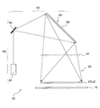
- FIG. 1 is a diagram showing a schematic configuration of an exposure apparatus according to a basic form of the present invention.
- the figure explaining the principle of operation of the illuminating device 40 of FIG. The figure explaining a mode that the image of a scattering plate is formed in the hologram recording medium 55 as an interference fringe.
- FIG. The figure which shows schematic structure of the exposure apparatus which concerns on one application form of this invention.
- the figure which shows schematic structure of the exposure apparatus which concerns on the 2nd Embodiment of this invention The figure which shows an example of the irradiation apparatus provided with the scanning device which can be rotated to biaxial direction. The figure which shows the example which makes parallel light inject into the hologram recording medium. The figure which shows schematic structure of the irradiation apparatus 60 which concerns on 3rd Embodiment using a lens array.
- the exposure apparatus according to the first embodiment of the present invention has a configuration capable of effectively preventing speckle as a basic form. Furthermore, an exposure apparatus according to one application form of the present invention is characterized by including an imaging optical system in addition to the configuration of the basic form. In the following description, first, the basic form of the present invention will be described with reference to FIGS.
- FIG. 1 is a view showing the schematic arrangement of an exposure apparatus according to the basic form of the present invention.
- the exposure apparatus 10 shown in FIG. 1 includes an optical element 50, an irradiation apparatus 60, and a light modulator 30.
- the coherent light modulated by the light modulator 30 is guided to the surface of the photosensitive medium 15.
- the illumination device 40 is configured by the optical element 50 and the irradiation device 60.
- the optical element 50 has a hologram recording medium 55 that can reproduce an image of a scattering plate in an illuminated area (predetermined area) LZ. Details of the hologram recording medium 55 will be described later.
- the irradiation device 60 irradiates the optical element 50 with coherent light so that the coherent light scans the surface of the optical element 50.
- the irradiation device 60 includes a laser light source 61 that emits coherent light, and a scanning device 65 that scans the surface of the optical element 50 with the coherent light emitted from the laser light source 61.
- the light modulator 30 is, for example, a transmissive or reflective reticle (mask).
- an optical image corresponding to the reticle pattern is formed on the surface of the photosensitive medium 15 and can be used as an exposure apparatus for manufacturing a semiconductor element.
- the light modulator 30 may be a transmissive liquid crystal microdisplay.
- the light modulator 30 illuminated in a planar shape by the illumination device 40 selects and transmits coherent light for each pixel, whereby a modulated image (light image) having a fine pattern is formed on the photosensitive medium 15. Can be formed.
- the incident surface of the light modulator 30 has the same shape and size as the illuminated region LZ where the illumination device 40 emits coherent light.
- the coherent light from the illumination device 40 can be used with high efficiency for exposure of the photosensitive medium 15.
- the photosensitive medium 15 is, for example, a semiconductor wafer coated with a resist pattern.
- the type of the photosensitive medium 15 is not particularly limited, and a film coated with a photosensitive agent may be used.
- the photosensitive medium 15 is arranged as close as possible to the light modulator 30.
- the optical modulator 30 is, for example, a mask
- the coherent light is diffracted at the edge, and a diffraction image is obtained.
- the influence of the diffraction image increases as the distance between the light modulator 30 and the photosensitive medium 15 increases, and the original light image by the mask becomes blurred. Therefore, in this basic embodiment, the photosensitive medium 15 is arranged as close as possible to the optical modulator 30 in order to reduce the influence of the diffraction image.
- the photosensitive medium 15 since the photosensitive medium 15 must be arranged as close as possible to the light modulator 30, the light modulator 30 is limited to a transmissive member (such as a reticle or a liquid crystal micro display), and a reflective member. Is difficult to implement.
- a transmissive member such as a reticle or a liquid crystal micro display
- FIG. 2 is a diagram for explaining the operating principle of the illumination device 40 of FIG. In FIG. 2, only some components in the lighting device 40 are illustrated for the sake of simplicity of explanation. Hereinafter, the basic operation principle of the illumination device 40 of FIG. 1 will be described with reference to FIG.
- the hologram recording medium 55 constituting the optical element 50 can receive the coherent light emitted from the irradiation device 60 as the reproduction illumination light La, and can diffract the coherent light with high efficiency.
- the hologram recording medium 55 reproduces the image 5 of the scattering plate 6 in the illuminated area LZ by diffracting coherent light incident on each position, in other words, each minute area that should also be called each point. Can be done.
- the irradiation device 60 is configured so that the coherent light irradiated to the hologram recording medium 55 scans the hologram recording medium 55 by the scanning device 65. Therefore, at a certain moment, the irradiation device 60 irradiates a minute area on the surface of the hologram recording medium 55 with coherent light.
- the coherent light emitted from the irradiation device 60 and scanned on the hologram recording medium 55 satisfies the diffraction condition of the hologram recording medium 55 at each position on the hologram recording medium 55 (each minute region, the same applies hereinafter).
- the incident light is incident at a proper incident angle.
- the coherent light incident on each position of the hologram recording medium 55 from the irradiation device 60 is diffracted by the hologram recording medium 55 and illuminates a predetermined region that overlaps at least partly.
- the coherent light incident on each position of the hologram recording medium 55 from the irradiation device 60 is diffracted by the hologram recording medium 55 to illuminate the same illuminated region LZ. .
- the coherent light incident on each position of the hologram recording medium 55 from the irradiation device 60 is superimposed on the illuminated region LZ to reproduce the image 5 of the scattering plate 6. It is like that. That is, the coherent light that has entered the hologram recording medium 55 from the irradiation device 60 is diffused (expanded) by the optical element 50 and enters the illuminated area LZ.
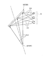
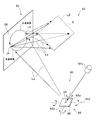
- FIG. 3 is a diagram for explaining how the image of the scattering plate is formed on the hologram recording medium 55 as interference fringes.
- the scattering plate 6 is a reference member that scatters light, and a specific form of the reference member is not limited.
- the hologram recording medium 55 is manufactured using the scattered light from the actual scattering plate 6 as the object light Lo.
- FIG. 3 shows a state where the photosensitive light 58 having photosensitivity that forms the hologram recording medium 55 is exposed to the reference light Lr and the object light Lo, which are coherent light beams having coherence with each other. Has been.
- the reference light Lr for example, laser light from a laser light source 61 that oscillates laser light in a specific wavelength range is used.
- the reference light Lr passes through the condensing element 7 made of a lens and enters the hologram photosensitive material 58.
- the laser light for forming the reference light Lr is incident on the condensing element 7 as a parallel light beam parallel to the optical axis of the condensing element 7.
- the reference light Lr passes through the condensing element 7, so that it is shaped (converted) into a convergent light beam from the parallel light beam so far, and is incident on the hologram photosensitive material 58.
- the focal position FP of the convergent light beam Lr is at a position past the hologram photosensitive material 58. That is, the hologram photosensitive material 58 is disposed between the light condensing element 7 and the focal position FP of the convergent light beam Lr condensed by the light condensing element 7.
- the object light Lo is incident on the hologram photosensitive material 58 as scattered light from a scattering plate 6 made of, for example, opal glass.
- the hologram recording medium 55 to be manufactured is a reflection type, and the object light Lo is incident on the hologram photosensitive material 58 from the surface opposite to the reference light Lr.
- the object light Lo is premised on having coherency with the reference light Lr. Therefore, for example, the laser light oscillated from the same laser light source 61 can be divided, and one of the divided light can be used as the reference light Lr and the other can be used as the object light Lo.
- a parallel light beam parallel to the normal direction to the plate surface of the scattering plate 6 is incident on and scattered by the scattering plate 6, and the scattered light transmitted through the scattering plate 6 is the object light Lo.
- the light enters the hologram photosensitive material 58.
- the object light Lo from the scattering plate 6 is incident on the hologram photosensitive material 58 with a substantially uniform light amount distribution. Is possible.
- the object light Lo is incident on each position of the hologram photosensitive material 58 with a substantially uniform light amount from the entire area of the exit surface 6 a of the scattering plate 6. It becomes easy. In such a case, the light incident on each position of the obtained hologram recording medium 55 reproduces the image 5 of the scattering plate 6 with the same brightness, and the reproduced image of the scattering plate 6. It can be realized that 5 is observed with approximately uniform brightness.
- the hologram recording material 58 when the hologram recording material 58 is exposed to the reference light Lr and the object light Lo, an interference fringe formed by the interference of the reference light Lr and the object light Lo is generated. It is recorded on the hologram recording material 58 as a pattern (in the case of a volume hologram, for example, a refractive index modulation pattern). Thereafter, appropriate post-processing corresponding to the type of the hologram recording material 58 is performed, and the hologram recording material 55 is obtained.
- a pattern in the case of a volume hologram, for example, a refractive index modulation pattern
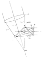
- FIG. 4 is a diagram for explaining a state in which the image of the scattering plate is reproduced using the interference fringes formed on the hologram recording medium 55 obtained through the exposure process of FIG.
- the hologram recording medium 55 formed of the hologram photosensitive material 58 of FIG. 3 is light having the same wavelength as the laser light used in the exposure process, and the optical path of the reference light Lr in the exposure process The light traveling in the opposite direction satisfies the Bragg condition. That is, as shown in FIG. 4, the reference point SP positioned with respect to the hologram recording medium 55 in the same positional relationship as the relative position of the focal point FP (see FIG. 3) with respect to the hologram photosensitive material 58 during the exposure process.
- the divergent light beam that diverges from the light beam and has the same wavelength as the reference light Lr during the exposure process is diffracted by the hologram recording medium 55 as the reproduction illumination light La, and is relative to the hologram photosensitive material 58 during the exposure process.
- the reproduced image 5 of the scattering plate 6 is generated at a specific position with respect to the hologram recording medium 55 that has the same positional relationship as the position (see FIG. 3).
- the reproduction light (light obtained by diffracting the reproduction illumination light La by the hologram recording medium 55) Lb that generates the reproduction image 5 of the scattering plate 6 travels from the scattering plate 6 toward the hologram photosensitive material 58 during the exposure process.
- Each point of the image 5 of the scattering plate 6 is reproduced as light traveling in the opposite direction along the optical path of the object light Lo that has been emitted.
- the scattered light Lo emitted from each position on the exit surface 6 a of the scattering plate 6 during the exposure process is diffused so as to be incident on almost the entire region of the hologram photosensitive material 58. Yes (spread).
- the object light Lo from the entire area of the exit surface 6 a of the scattering plate 6 is incident on each position on the hologram photosensitive material 58, and as a result, information on the entire exit surface 6 a is placed on each position of the hologram recording medium 55. Each is recorded. For this reason, each light which forms the divergent light beam from the reference point SP functioning as the reproduction illumination light La shown in FIG. 4 is incident on each position of the hologram recording medium 55 independently and has the same contour.
- the image 5 of the scattering plate 6 can be reproduced at the same position (illuminated area LZ).
- the irradiation apparatus 60 includes a laser light source 61 that generates coherent light, and a scanning device 65 that changes the traveling direction of the coherent light from the laser light source 61. .
- the laser light source 61 emits, for example, ultraviolet light. Alternatively, a plurality of laser light sources 61 that emit laser beams of different wavelength bands may be used. When a plurality of laser light sources 61 are used, the laser light from each laser light source 61 irradiates the same point on the scanning device 65. Thereby, the hologram recording medium 55 is illuminated with the reproduction illumination light in which the illumination colors of the laser light sources 61 are mixed.
- Coherent light from the laser light source 61 reflected by the scanning device 65 is incident on the hologram recording medium 55, so that the image 5 of the scattering plate 6 having an illumination color corresponding to the wavelength band of the laser light source 61 is illuminated. It is generated throughout the LZ.
- the scanning device 65 changes the traveling direction of the coherent light with time, and directs it in various directions so that the traveling direction of the coherent light is not constant. As a result, the coherent light whose traveling direction is changed by the scanning device 65 scans the incident surface of the hologram recording medium 55 of the optical element 50.
- the scanning device 65 includes a reflecting device 66 having a reflecting surface 66a that can be rotated about one axis RA1.
- FIG. 5 is a diagram for explaining the scanning path of the scanning device 65.
- the reflection device 66 includes a mirror device having a mirror as a reflection surface 66a that can be rotated about one axis RA1.
- This mirror device 66 changes the traveling direction of coherent light from the laser light source 61 by changing the orientation of the mirror 66a.
- the mirror device 66 generally receives coherent light from the laser light source 61 at the reference point SP.
- the coherent light whose traveling direction has been finally adjusted by the mirror device 66 enters the hologram recording medium 55 of the optical element 50 as reproduction illumination light La (see FIG. 4) that can form one light beam diverging from the reference point SP. obtain.
- the coherent light from the irradiation device 60 scans on the hologram recording medium 55, and the image of the scattering plate 6 in which the coherent light incident on each position on the hologram recording medium 55 has the same contour. 5 is reproduced at the same position (illuminated area LZ).
- the reflection device 66 is configured to rotate the mirror 66a along one axis RA1.
- the rotation axis RA ⁇ b> 1 of the mirror 66 a has an XY coordinate system defined on the plate surface of the hologram recording medium 55 (that is, the XY plane is parallel to the plate surface of the hologram recording medium 55. It extends parallel to the Y axis of the (XY coordinate system). Then, since the mirror 66a rotates around the axis line RA1 parallel to the Y axis of the XY coordinate system defined on the plate surface of the hologram recording medium 55, the coherent light from the irradiation device 60 is applied to the optical element 50.
- the incident point IP reciprocates in a direction parallel to the X axis of the XY coordinate system defined on the plate surface of the hologram recording medium 55. That is, in the example shown in FIG. 5, the irradiation device 60 irradiates the optical element 50 with coherent light so that the coherent light scans on the hologram recording medium 55 along a linear path.
- the scanning device 65 configured by the mirror device 66 or the like is a member that can rotate at least around the axis A1, and is configured by using, for example, MEMS.
- the rotation frequency is not particularly limited as long as the optical element 50 can be scanned with coherent light for at least one period during one exposure time.
- the hologram recording material 58 may shrink when the hologram recording medium 55 is produced.
- the traveling direction of the light incident on the hologram recording medium 55 of the optical element 50 does not take exactly the same path as the one light beam included in the divergent light beam from the reference point SP, it is illuminated.
- the image 5 can be reproduced in the region LZ.
- the mirror (reflecting surface) 66a of the mirror device 66 constituting the scanning device 65 is inevitably deviated from the rotation axis RA1. Therefore, when the mirror 66a is rotated around the rotation axis RA1 that does not pass through the reference point SP, the light incident on the hologram recording medium 55 may not be a single light beam that forms a divergent light beam from the reference point SP. is there.
- the image 5 can be substantially reproduced by being superimposed on the illuminated region LZ by coherent light from the irradiation device 60 having the illustrated configuration.
- the scanning device 65 does not necessarily have to be a member that reflects the coherent light. Instead of reflecting, the scanning device 65 may cause the coherent light to be refracted or diffracted to scan the optical element 50.
- the irradiation device 60 irradiates the optical element 50 with coherent light so that the coherent light scans on the hologram recording medium 55 of the optical element 50.
- coherent light having a specific wavelength traveling along a certain direction is generated by the laser light source 61, and this coherent light is irradiated to the scanning device 65, and the traveling direction thereof is varied. More specifically, each coherent light travels toward the hologram recording medium 55 at a reflection angle corresponding to the incident angle from the laser light source 61.
- the scanning device 65 makes each position on the hologram recording medium 55 incident coherent light of a corresponding specific wavelength at an incident angle that satisfies the Bragg condition at the position.
- the coherent light incident on each position is reproduced by the diffraction by the interference fringes recorded on the hologram recording medium 55 so as to overlap the entire illuminated area LZ and reproduce the image 5 of the scattering plate 6. That is, the coherent light that has entered the hologram recording medium 55 from the irradiation device 60 is diffused (expanded) by the optical element 50 and enters the entire illuminated area LZ. In this way, the irradiation device 60 illuminates the illuminated area LZ with coherent light.
- the laser light source 61 has a plurality of laser light sources 61 that emit light in different colors
- the image 5 of the scattering plate 6 is reproduced in each color in the illuminated region LZ. Therefore, when these laser light sources 61 emit light at the same time, the illuminated area LZ is illuminated with white in which three colors are mixed.
- the incident position of the coherent light from the scanning device 65 on the hologram recording medium 55 moves with time within each position by driving the scanning device 65.
- an optical image can be formed on the photosensitive medium 15 without conspicuous speckles.
- the mode refers to speckle patterns that are uncorrelated with each other.
- coherent light is projected from different directions onto the same screen from a plurality of laser light sources 61
- coherent light from the same laser light source 61 is projected onto the screen from different directions every unit time, the number of times the incident direction of the coherent light has changed during the time that cannot be resolved by the human eye Will exist.
- the interference patterns of light are overlapped uncorrelatedly and averaged, and as a result, speckles observed by the observer's eyes become inconspicuous.
- the irradiation device 60 described above irradiates the optical element 50 with coherent light so that the coherent light scans on the hologram recording medium 55. Further, the coherent light incident on each position of the hologram recording medium 55 from the irradiation device 60 illuminates the entire illuminated area LZ, but the illumination directions of the coherent light that illuminate the illuminated area LZ are mutually different. Different. Since the position on the hologram recording medium 55 where the coherent light enters changes with time, the incident direction of the coherent light to the illuminated region LZ also changes with time.
- the illuminated area LZ As a reference, coherent light constantly enters each position in the illuminated area LZ, but the direction of incidence always changes. As a result, the modulated light from the light modulator 30 is incident on the photosensitive medium 15 disposed close to the light modulator 30 overlapping the illuminated area LZ while changing the optical path over time.
- coherent light continuously scans on the hologram recording medium 55.
- the incident direction of coherent light incident on the illuminated area LZ from the irradiation device 60 via the optical element 50 also changes continuously.
- the pattern of speckles generated on the illuminated area LZ also changes greatly, and is uncorrelated.
- a speckle pattern is superimposed.
- the frequency of scanning devices 65 such as MEMS mirrors and polygon mirrors that are commercially available is usually several hundred Hz or higher, and scanning devices 65 that reach tens of thousands of Hz are not uncommon.
- the incident direction of coherent light changes temporally at each position of the illuminated region LZ, and this change is a speed that cannot be resolved by human eyes. It is. Accordingly, if a screen is arranged in the illuminated area LZ, speckles generated corresponding to each scattering pattern are superimposed and averaged and observed by the observer, so that the image displayed on the screen Speckle can be made very inconspicuous for an observer who observes the above.
- the light modulator 30 is disposed at a position overlapping the illuminated area LZ. As a result, speckle becomes inconspicuous at any position on the optical modulator 30.
- the photosensitive medium 15 is arranged as close as possible to the optical modulator 30, the optical image modulated by the optical modulator 30 can be guided to the surface of the photosensitive medium 15 as faithfully as possible.
- the surface of the optical modulator 30 is a mirror surface
- the coherent light from the hologram recording medium 55 is reflected by this mirror surface.
- the hologram recording medium 55 itself is directly observed, so that speckle is visually recognized.
- speckles are visually recognized is that the mirror surface cannot diffuse the coherent light from the hologram recording medium 55 to generate a plurality of new speckle patterns.
- hologram recording in which each point always generates the same wavefront. This is because the wavefront from the medium 55 is reflected on the mirror surface and observed as it is.
- the light diffusing element 21 may be disposed between the hologram recording medium 55 and the light modulator 30 as shown by a broken line in FIG.
- the light diffusing element 21 is a relief or a volume hologram recording medium as a representative example, but the material is not particularly limited as long as the surface is a diffusing surface.
- one glass surface processed into a ground glass shape (opaque) may be used.
- the light diffusing element 21 may be opal glass, a relief diffusing plate, a microlens array, or the like.
- the coherent light diffused by the light diffusing element 21 is incident on the light modulator 30, and the surface of the light modulator 30 or the photosensitive medium 15 is a mirror surface. Speckle is less noticeable on these surfaces.
- each point on the hologram recording medium 55 is always irradiated with coherent light having a constant wavefront.
- coherent light is incident on each point of the light diffusing element 21 at different angles with time from each point of the hologram recording medium 55, the scattering characteristics at each point of the light diffusing element 21 change with time. Wavefronts that differ over time can be generated continuously.
- coherent light generated by the light diffusing element 21 and changing in wavefront with time is incident on the optical modulator 30. Therefore, on the optical modulator 30, the diffusion pattern of the coherent light from the light diffusing element 21 changes with time. As a result, even if the optical modulator whose part is a mirror is directly observed, speckles are temporally changed. Superimposed to make it inconspicuous.
- speckles observed by humans include not only speckles on the photosensitive medium 15 side caused by scattering of coherent light on the photosensitive medium 15 but also coherent before being projected onto the photosensitive medium 15. Speckle on the optical element 50 side due to light scattering can also occur.
- the speckle pattern generated on the optical element 50 side is projected onto the photosensitive medium 15 via the light modulator 30 so that it can be recognized by the observer.
- the coherent light continuously scans on the hologram recording medium 55, and the coherent light incident on each position of the hologram recording medium 55 is superimposed on the optical modulator 30, respectively. The entire illuminated area LZ is illuminated.
- the hologram recording medium 55 forms a new wavefront that is separate from the wavefront used to form the speckle pattern, and is complex and uniform through the illuminated region LZ and further through the light modulator 30. Illuminate the screen.
- the speckle pattern generated on the optical element 50 side becomes invisible.
- the scanning device 65 is used to scan the coherent light on the hologram recording medium 55, and the light modulation in which the coherent light irradiated from the hologram recording medium 55 overlaps the illuminated region LZ. Incident on the vessel 30. Further, since the photosensitive medium 15 is disposed in the vicinity of the optical modulator 30, the coherent light can be guided on the photosensitive medium 15 without conspicuous speckles with a very simple configuration.
- the light diffusing element 21 between the irradiation device 60 and the light modulator 30, it is possible to make the speckle inconspicuous even for the reflected light from the light modulator 30.
- the exposure apparatus of FIG. 1 is based on the premise that proximity exposure is performed without providing an imaging optical system between the light modulator 30 and the photosensitive medium 15.
- an application form described below is characterized in that an imaging (projection) optical system is provided.
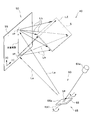
- FIG. 6 is a view showing the schematic arrangement of an exposure apparatus according to one application mode of the present invention.
- the same components as those in FIG. 1 are denoted by the same reference numerals, and different points will be mainly described below.
- the exposure apparatus 10a in FIG. 6 includes an optical element 50, an irradiation apparatus 60, and a light modulator 30 in the same manner as in FIG. 1, and in addition, between the light modulator 30 and the photosensitive medium 15.
- the imaging optical system 25 is disposed, and the light diffusing element 21 is disposed between the irradiation device 60 and the light modulator 30.
- the imaging optical system 25 forms an image on the photosensitive medium 15 with coherent light modulated by the light modulator 30. By providing the imaging optical system 25, enlargement exposure or reduction exposure is possible.
- the light diffusing element 21 is not necessarily essential, but in the exposure apparatus 10a of FIG. 6, the light diffusing element 21 is essential. Hereinafter, the reason will be described in detail.
- the incident angle of the coherent light from the irradiation device 60 to the illuminated area LZ also changes continuously and is incident on the photosensitive medium 15 from the optical element 50.
- the incident angle of coherent light also changes continuously. Therefore, when a human visually recognizes the surface of the photosensitive medium 15 from a distant position, the coherent light scattering pattern having no correlation is multiplexed and visually recognized by the human eye. Therefore, speckles generated corresponding to each scattering pattern are superposed and averaged and observed by the observer, and the speckles are not visually recognized.
- the photosensitive medium 15 is for recording a light image from the light modulator 30. Recording an optical image on the photosensitive medium 15 is equivalent to recording an image that enters the human eye when the hologram recording medium 55 side is desired from the photosensitive medium 15.
- An imaging optical system 25 exists between the photosensitive medium 15 and the optical modulator 30, and each point on the imaged photosensitive medium 15 is recorded on the hologram via the imaging optical system 25 and the optical modulator 30.
- the light diffusing element 21 when the light diffusing element 21 is disposed between the hologram recording medium 55 and the light modulator 30, coherent light having different incident angles with time is incident on each point of the light diffusing element 21, and scattering characteristics that vary with time. Light, that is, different wavefronts.
- the wavefront of the coherent light irradiated from each point of the light diffusing element 21 changing with time
- the wavefront changes with time.
- the changing coherent light can be seen, and an uncorrelated speckle pattern is superimposed on the photosensitive medium 15, so that the speckle becomes inconspicuous.
- the light diffusion element 21 is arranged between the hologram recording medium 55 and the light modulator 30 in this application mode.
- the illuminated region of the coherent light diffused by the optical element 50 is preferably provided on the light diffusing element 21. In this way, the diffused light from each point of the optical element 50 becomes incident light that changes with time on the light diffusing element 50, and speckles are noticeable when the optical element 50 side is desired from the photosensitive medium 15. Disappear.
- the light diffusing element 21 may not be disposed anywhere between the irradiation device 60 and the light modulator 30.
- the light diffusing element 21 when the light diffusing element 21 is near the light modulator 30, more specifically, when the light diffusing element 21 is disposed within the length of the focal depth of the imaging optical system 25 from the light modulator 30, the light diffusion The optical image of the element 21 is reflected on the photosensitive medium 15.
- the light diffusing element 21 when the light diffusing element 21 is disposed farther from the optical modulator 30 than the depth of focus of the imaging optical system 25, the light image of the light diffusing element 21 is completely blurred, and the photosensitive medium 15 There is no risk of imaging. Therefore, it is desirable that the light diffusing element 21 is disposed between the irradiation device 60 and the light modulator 30 and farther from the light modulator 30 than the length of the focal depth of the imaging optical system 25.
- the light diffusing element 21 has a flat surface such as opal glass and the illuminance is relatively uniform, even if the light diffusing element 21 is arranged within the length of the focal depth of the imaging optical system 25, the light diffusing is performed on the photosensitive medium 15. There may be a case where the image of the element 21 does not affect the image quality of exposure. In this case, it is not essential to dispose the light diffusing element 21 farther than the focal depth of the imaging optical system 25.
- the scanning device 65 is used to scan the coherent light on the hologram recording medium 55, and the light diffusing element 21 diffuses the coherent light irradiated from the hologram recording medium 55. .
- the interference pattern of coherent light irradiated from each point of the light diffusing element 21 is changed. Since the coherent light emitted from the light diffusing element 21 is incident on the optical modulator 30, speckles can be made inconspicuous on the optical modulator 30. Therefore, even if the imaging optical system 25 exists between the light modulator 30 and the photosensitive medium 15, speckles are not noticeable on the photosensitive medium 15.
- exposure apparatuses 10 and 10a The following is the contents common to the above-described exposure apparatuses 10 and 10a, and is hereinafter referred to as “exposure apparatus according to the present embodiment”.
- Speckle Phenomena in Optics, Joseph W. Goodman, Roberts & Co., 2006 proposed a method that uses a value called speckle contrast (unit%) as a parameter indicating the degree of speckle generated on the screen. ing.
- speckle contrast is defined as a value obtained by dividing the standard deviation of the actual luminance variation on the screen divided by the average luminance value when displaying a test pattern image that should have a uniform luminance distribution. Amount. The larger the speckle contrast value is, the larger the speckle occurrence level on the screen is, which indicates that the spot-like luminance unevenness pattern is more prominently presented to the observer.
- FIG. 7 is a diagram showing the result of measuring speckle contrast with and without using the hologram recording medium 55 described above.
- FIG. 7A shows a case in which a laser beam is directly applied to the illuminated region LZ without using the scanning device 65 and the optical element 50
- FIG. 7C shows the case where a relief diffusion plate is used as the optical element 50
- FIG. 7D shows a case where a single color LED is used instead of the laser light source 61 as the irradiation device 60 and the emitted light of the single color LED is directly irradiated onto the illuminated area LZ.
- the problem of speckle generation is a problem inherent to practical use when a coherent light source such as a laser beam is used, and is a problem that need not be considered in an apparatus using a non-coherent light source such as an LED.
- the speckle contrast is superior to the case of using the monochromatic LED according to the present embodiment, but it is considered that the light diffusing element 21 is not used for illumination of the monochromatic LED. From the above, it can be said that the exposure apparatuses 10 and 10a according to the present embodiment were able to sufficiently cope with speckle defects.
- the optical element 50 for making speckles inconspicuous can also function as an optical member for shaping and adjusting the beam form of coherent light emitted from the irradiation device 60. Therefore, the optical system can be reduced in size and simplified.
- coherent light incident on a specific position in each recording area of the hologram recording medium 55 generates the image 5 of the scattering plate 6 in each color over the entire illuminated area LZ.
- the optical modulator 30 is arranged so as to overlap the image 5. For this reason, all the light diffracted by the hologram recording medium 55 can be used for image formation, and the use efficiency of the light from the laser light source 61 is excellent.
- the light modulator 30 in one application form described above may be a transmissive or reflective photomask, or may be a micromirror device or a reflective LCOS (Liquid Crystal On Silicon).
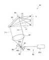
- FIG. 8 is a view showing the schematic arrangement of an exposure apparatus according to the second embodiment of the present invention.
- the exposure apparatus 10 in FIG. 8 includes an irradiation device 60, an optical element 50, a first diaphragm 31, a condensing optical system 32, a light modulator 30, and an imaging optical system 25, and includes an optical device.
- An image formed on the modulator 30 is exposed on an object to be exposed (photosensitive medium) 15.
- the surface of the object to be exposed 15 is the XY plane, and the axis orthogonal to the XY plane is the Z axis.
- the irradiation device 60 is an optical system that illuminates the optical element 50 as an illuminated area, and changes the incident angle with respect to the effective area of the optical element 50 with the illumination light Lb that is emitted with its direction changing over time. While illuminating the optical element 50. At that time, the illumination light Lb changes its direction with time, so that it is necessary to illuminate the entire effective area of the optical element 50 by overlapping the illumination light Lb emitted at each time with time.
- the illumination light Lb is always the effective area of the optical element 50, that is, the area in the optical element 50 necessary for forming an image on the object to be exposed 15, regardless of the emission direction of the illumination light Lb. We will illuminate the whole.
- FIG. 8 shows the state of the illumination lights Lb (t1) and Lb (t2) near the outermost end. Actually, the directions of the illumination lights Lb are Lb (t1) and Lb (t2). It will change continuously between.
- the optical element 50 is an optical element that diffuses incident light, and for example, glass having one surface processed into a ground glass (opaque), opal glass, or a random phase diffusion plate is used.
- a hologram, a microlens array, or the like may be used as the optical element 50.
- coherent light diffused by the optical element 50 is incident on the optical modulator 30, and is generated by the optical modulator 30 and other optical components. It is possible to make the speckle to be inconspicuous.
- the condensing optical system 32 is an optical element that condenses the coherent light emitted from the optical element 50 on the illuminated region of the optical modulator 30. In the present embodiment, the light utilization efficiency is improved by condensing the coherent light emitted from the optical element 50 in the illumination area in this way.
- the condensing optical system 32 is a conjugate of the first diaphragm 31 disposed in the vicinity of the optical element 50 and the second diaphragm 25b disposed in the imaging optical system 25, so that light modulation is performed.
- the imaging characteristics at all positions of the vessel 30 are made uniform.
- the first diaphragm 31 may be formed by the edge of the optical element 50 or its effective area.
- the light modulator 30 is, for example, a transmissive or reflective reticle (photomask).
- an optical image corresponding to the reticle pattern is formed on the surface of the object to be exposed 15 and can be used as an exposure apparatus for manufacturing a semiconductor element.
- the light modulator 30 may be a display element such as a liquid crystal micro display that forms an image based on an input video signal instead of a photomask. Also in this case, the display element may be either a transmission type or a reflection type.
- the light modulator 30 illuminated by the optical element 50 selects and transmits or reflects coherent light for each pixel, so that a modulated image (light image) having a fine pattern can be formed on the object to be exposed 15.
- the exposed body 15 is, for example, a semiconductor wafer for forming a resist pattern.
- the type of the object to be exposed 15 is not limited, and may be a film coated with a photosensitive agent.
- the imaging optical system 25 is an optical element that forms an image formed on the light modulator 30 on the exposure target 15 and exposes the image.
- the imaging optical system 25 is disposed between the pair of convex lenses 25a and 25c.
- the second diaphragm 25b is configured. As described above, the second diaphragm 25b is conjugate with the first diaphragm 31 disposed in the vicinity of the optical element 50.
- the irradiation device 60 of the exposure apparatus in FIG. 8 illuminates the entire effective area of the optical element 50 while changing the incident angle with time.
- the effective area of the optical element 50 is preferably set to an always illuminated area regardless of the direction of the illumination light Lb emitted from the irradiation device 60 in order to achieve uniform luminance.
- the outgoing light from the optical element 50 illuminates the light modulator 30 via the condensing optical system 32.
- the condensing optical system 32 illuminates the entire illuminated area of the light modulator 30.
- the illumination light Lb incident on the optical element 50 is incident while changing the incident angle with time
- the diffused light emitted from the optical element 50 also illuminates the light modulator 30 while changing the angle with time. Will be. Accordingly, speckles generated in the illuminated region of the light modulator 30 are overlapped and averaged over an exposure time period that is an illumination time for the exposed object 15, and as a result, are generated on the exposed object 15. Irradiation unevenness can be suppressed, and an image formed on the light modulator 30 can be accurately exposed on the exposure target 15.
- a part of the coherent light from the irradiation device 60 passes through the hologram recording medium 55 without being diffracted by the hologram recording medium 55. Such light is called zero order light. If zero-order light enters the illuminated area LZ, an abnormal area (a dotted area, a linear area, or a planar area) in which the brightness (luminance) increases sharply compared with the surrounding area is the illuminated area LZ. Will occur within.
- the reflection type hologram recording medium 55 (hereinafter referred to as reflection type holo)
- the light modulator 30 and the projection optical system 25 are not arranged in the direction in which the zeroth order light travels, and therefore the zeroth order light is relatively easy.
- the transmission type hologram recording medium 55 (hereinafter referred to as transmission type holo)
- the arrangement location of the scanning device 65, the light modulator 30, and the projection optical system 25 according to the travel path of the 0th-order light so that the zero-order light does not pass through the light modulator 30 and the projection optical system 25. Need to design.
- the reflection type holo has higher wavelength selectivity than the transmission type holo. That is, the reflection type holo can diffract coherent light having a desired wavelength only by a desired layer even if interference fringes corresponding to different wavelengths are laminated.
- the reflection type holo is also excellent in that it is easy to remove the influence of zero-order light.
- the transmission type holo has a wide diffractable spectrum and a wide tolerance of the laser light source 61.
- interference fringes corresponding to different wavelengths are laminated, coherent light of a desired wavelength is generated even in layers other than the desired layer. It will be diffracted. Therefore, in general, it is difficult to make the transmission type holo a laminated structure.
- the scanning device 65 is an example of the uniaxial rotation type mirror device 66 that changes the traveling direction of the coherent light by reflection, the scanning device 65 is not limited thereto.
- the scanning device 65 has a second rotation in which the mirror (reflection surface 66a) of the mirror device 66 intersects not only the first rotation axis RA1 but also the first rotation axis RA1. It may be rotatable about the axis RA2. In the example shown in FIG.
- the second rotation axis RA2 of the mirror 66a is a first rotation axis RA1 extending in parallel with the Y axis of the XY coordinate system defined on the plate surface of the hologram recording medium 55.
- the incident point IP of the coherent light from the irradiation device 60 to the optical element 50 is the plate of the hologram recording medium 55. It is possible to move in a two-dimensional direction on the surface. For this reason, as shown in FIG. 9 as an example, the incident point IP of the coherent light to the optical element 50 can be moved on the circumference.
- the scanning device 65 may include two or more mirror devices 66.
- the mirror 66a of the mirror device 66 can be rotated only about a single axis, the incident point IP of the coherent light from the irradiation device 60 to the optical element 50 is expressed by the hologram recording medium 55. It can be moved in a two-dimensional direction on the plate surface.
- mirror device 66a included in the scanning device 65 includes a MEMS mirror, a polygon mirror, and the like.
- the scanning device 65 may include a device other than the reflection device (for example, the mirror device 66 described above) that changes the traveling direction of the coherent light by reflection.
- the scanning device 65 may include a refractive prism, a lens, and the like.
- the scanning device 65 is not essential, and the light source 61 of the irradiation device 60 is configured to be displaceable (movable, swinging, rotating) with respect to the optical element 50, and the light source 61 is displaced by the displacement of the light source 61 with respect to the optical element 50.
- the coherent light irradiated from the above may be scanned on the hologram recording medium 55.
- the light source 61 of the irradiation device 60 has been described on the premise that the light source 61 oscillates a laser beam shaped as a linear light beam, but is not limited thereto.
- the coherent light irradiated to each position of the optical element 50 is shaped by the optical element 50 into a light beam that enters the entire illuminated area LZ. Therefore, there is no inconvenience even if the coherent light irradiated from the light source 61 of the irradiation device 60 to the optical element 50 is not accurately shaped. For this reason, the coherent light generated from the light source 61 may be diverging light.
- the cross-sectional shape of the coherent light generated from the light source 61 may not be a circle but an ellipse or the like.
- the transverse mode of the coherent light generated from the light source 61 may be a multimode.
- the coherent light is incident on a region having a certain area instead of a point when entering the hologram recording medium 55 of the optical element 50.
- the light diffracted by the hologram recording medium 55 and incident on each position of the illuminated area LZ is multiplexed in angle.
- coherent light is incident on each position of the illuminated area LZ from a certain angle range. Speckle can be made more inconspicuous by such multiplexing of angles.
- the scanning device 65 may further include a condensing lens 67 disposed on the downstream side of the mirror device 66 along the optical path of the coherent light.
- the light from the mirror device 66 that travels along the optical path of the light beam constituting the divergent light beam becomes light that travels in a certain direction by the condenser lens 67.
- the irradiation device 60 causes the coherent light to be incident on the optical element 50 so as to follow the optical path of the light beam constituting the parallel light flux.
- a parallel light beam is used as the reference light Lr instead of the above-described convergent light beam.
- Such a hologram recording medium 55 can be produced and duplicated more easily.
- optical element 50 In the embodiment described above, an example in which the optical element 50 includes the reflective volume hologram 55 using a photopolymer has been described, but the present invention is not limited thereto. Further, the optical element 50 may include a volume hologram that is recorded using a photosensitive medium including a silver salt material. Furthermore, the optical element 50 may include a transmissive volume hologram recording medium 55 or a relief (embossed) hologram recording medium 55.
- a relief (embossed) hologram is recorded with hologram interference fringes due to the uneven structure on the surface.
- scattering due to the uneven structure on the surface may become a new speckle generation factor.
- the volume type hologram is preferable.
- the hologram interference fringe is recorded as a refractive index modulation pattern (refractive index distribution) inside the medium, it is not affected by scattering due to the uneven structure on the surface.
- the hologram recording medium 55 is preferably a volume hologram using a photopolymer.
- a so-called Fresnel type hologram recording medium 55 is produced, and a Fourier transform type hologram recording medium 55 obtained by performing recording using a lens is produced. It doesn't matter. However, when the Fourier transform type hologram recording medium 55 is used, a lens may also be used during image reproduction.
- the striped pattern (refractive index modulation pattern or concave / convex pattern) to be formed on the hologram recording medium 55 does not use the actual object light Lo and reference light Lr, but the planned wavelength and incident direction of the reproduction illumination light La. In addition, it may be designed using a computer based on the shape and position of the image to be reproduced.
- the hologram recording medium 55 obtained in this way is also called a computer-generated hologram.
- the hologram recording medium 55 as a computer-generated hologram corresponds to the coherent light in each wavelength range.
- the coherent light in each wavelength region may be diffracted in the corresponding region to reproduce an image.
- the optical element 50 includes the hologram recording medium 55 that expands the coherent light irradiated to each position and illuminates the entire illuminated area LZ using the expanded coherent light.
- the optical element 50 changes the traveling direction of the coherent light irradiated to each position and diffuses instead of the hologram recording medium 55 or in addition to the hologram recording medium 55 so that the entire area to be illuminated LZ is coherent light.
- the irradiating device 60 scans the lens array with the coherent light so as to irradiate the optical element 50 with the coherent light.
- the irradiation device 60 and the optical element 50 By configuring the irradiation device 60 and the optical element 50 so that the traveling direction of the coherent light incident on the position is changed by the lens array to illuminate the illuminated area LZ, speckles are effectively inconspicuous. Can be made.
- the example which comprises the irradiation apparatus 60 using a lens array is demonstrated.
- FIG. 11 is a diagram showing a schematic configuration of an irradiation apparatus 60 according to the third embodiment using a lens array.
- the irradiation apparatus 60 of this embodiment includes a light source 61, a scanning device 65, a first optical path conversion system 62, a lens array 63, and a second optical path conversion system 64.
- the exposure apparatus can be configured using another configuration excluding the light source 61 in the irradiation apparatus 60.
- the first optical path conversion system 62 is not an essential configuration.
- a beam shaping means for uniforming the intensity distribution in the cross-sectional direction of the coherent light emitted from the light source 61.
- a beam shaping means is provided so as to be uniform on the surface in the vicinity of the scanning device 65, and the surface and the one-dimensional light modulation element surface are set to be conjugate, thereby making the illuminated region uniform in intensity. It can be illuminated.
- the scanning device 65 of the present embodiment has a rotation center Ra in the Y-axis direction, and performs one-dimensional scanning that scans coherent light in the XZ plane. Even in this case, it is necessary to scan the incident surface of the lens array 63 and to illuminate the illuminated area sufficiently as a result.
- the coherent light incident from the light source 61 becomes scanning light La whose direction changes temporally by the scanning device 65 and is incident on the lens array 63 via the first optical path conversion system 62.
- FIG. 11 shows the state of the scanning lights La (t1) and La (t2) near the outermost end, but actually the scanning light La is between La (t1) and La (t2). Will move continuously.
- the first optical path conversion system 62 is an optical element that converts the scanning light La from the scanning unit 15 so as to be incident substantially perpendicular to the incident surface of the lens array 63, and uses a convex lens having a condensing function. Configured. By making the scanning light La ′ thus converted perpendicularly incident on each element lens constituting the lens array 63, the scanning light La ′ is incident on each element lens under the same conditions. . Therefore, it is possible to reduce the design burden, for example, by making the design of each element lens of the lens array 63 equal.
- the first optical path conversion system 62 is not necessarily provided, and can be dealt with by changing the element lens constituting the lens array 63 and the subsequent optical system according to the state of incident light. It is.
- the lens array 63 is an optical element in which a plurality of element lenses are arranged at a light scanning position (on the XY plane) by the scanning device 65, and the scanning light La ′ incident on each element lens is diverged light Lb. Convert to '.
- the size and shape of the element lens constituting the lens array 63 can be appropriately set as necessary.For example, a cylindrical lens array using a cylindrical lens as the shape of the element lens can be used. A microlens array composed of extremely small element lenses may be used.
- each element lens has a configuration in which a plurality of stages (two stages) are arranged in the optical axis direction (Z-axis direction).
- the coherent light emitted from the light source 61 is not necessarily emitted as parallel light, and may include a scattered component that is somewhat deviated from the parallel state.
- this scattering component can be suppressed by arranging a plurality of element lenses in the optical axis direction.
- the element lenses arranged in the optical axis direction have the same diameter and are arranged such that the central axis is aligned with the light traveling direction.
- the lens array 63 may have a configuration in which each element lens is configured in one stage in the optical axis direction.
- the second optical path conversion system 64 (“optical path conversion system” in the present invention) is an optical element that illuminates the optical element 50 as an illuminated area with the illumination light Lb emitted from the lens array 63.
- the illumination light Lb emitted from each point of the lens array 63 optically scanned by the optical scanning unit 15 illuminates the illuminated area with the illumination light Lb so as to overlap with time through the second optical path conversion system 64.
- the second optical path conversion system 64 preferably has a condensing function for diverging light Lb ′ emitted from the lens array 63 to illuminate an effective area of the optical element 50 as an illuminated area.
- the second optical path conversion system 64 converts the divergent light Lb ′ so as to become parallel light or substantially parallel light.
- the second optical path conversion system 64 only needs to have a function of suppressing the divergence angle, and a combination of a lens, a concave mirror, a mirror, and a prism is used. You may implement
- the illumination light Lb emitted from the second optical path conversion system 64 is sufficient to illuminate at least a part of the effective area of the optical element 50 at each time point and to illuminate the entire effective area by scanning with the scanning device 65. However, it is preferable that the illumination light Lb illuminates the entire effective area at each time point. According to such a configuration, it is possible to make the luminance distribution uniform in the effective area of the optical element 50.
- the effective area of the optical element 50 is overlapped with time and illuminated with coherent light, and the incident angle to each point of the effective area is changed with time. Can be illuminated.
- the diffused light emitted from the optical element 50 is averaged on the optical modulator 30 to suppress the generation of speckle, and as a result, the uneven irradiation of the image formed on the object to be exposed 15 is eliminated.
- the image formed on the light modulator 30 can be exposed to the object 15 with high accuracy.
- the irradiation device 60 is configured to be able to scan the coherent light on the optical element 50 in a one-dimensional direction, and the hologram recording medium 55 (or lens) of the optical element 50 is used.
- the array is configured to diffuse (spread and diverge) the coherent light irradiated to each position in a two-dimensional direction, whereby the illumination device 40 illuminates the two-dimensional illuminated area LZ An example to do.
- the present invention is not limited to such an example.
- the irradiation device 60 is configured to be able to scan the coherent light on the optical element 50 in a two-dimensional direction
- the hologram recording medium 55 (or lens array) of the optical element 50 is configured to diffuse (spread and diverge) the coherent light irradiated to each position in a two-dimensional direction.
- the illumination device 40 may illuminate the two-dimensional illuminated area LZ.
- the irradiation device 60 is configured to be able to scan the coherent light on the optical element 50 in a one-dimensional direction, and the hologram recording medium 55 (or lens array) of the optical element 50 is used. Is configured to diffuse (spread and diverge) the coherent light irradiated to each position in a one-dimensional direction, so that the illumination device 40 illuminates the one-dimensional illuminated region LZ. It may be.
- the scanning direction of the coherent light by the irradiation device 60 and the diffusion direction (expansion direction) of the hologram recording medium 55 (or lens array) of the optical element 50 may be parallel to each other.
- the irradiation device 60 is configured to be able to scan the coherent light on the optical element 50 in a one-dimensional direction or a two-dimensional direction, and the hologram recording medium 55 (or lens array) of the optical element 50 is placed at each position.
- the irradiated coherent light may be configured to diffuse (spread and diverge) in a one-dimensional direction.
- the optical element 50 has a plurality of hologram recording media 55 (or lens arrays), and sequentially illuminates the illuminated area LZ corresponding to each hologram recording medium 55 (or lens array). By doing so, the illumination device 40 may illuminate a two-dimensional area.
- each illuminated area LZ may be sequentially illuminated at a speed as if it were illuminated simultaneously by the human eye, or it can be recognized that the illuminated area LZ is also illuminated sequentially by the human eye. It may be illuminated sequentially at such a slow speed.
Landscapes
- Physics & Mathematics (AREA)
- General Physics & Mathematics (AREA)
- Optics & Photonics (AREA)
- Exposure And Positioning Against Photoresist Photosensitive Materials (AREA)
- Holo Graphy (AREA)
- Mechanical Optical Scanning Systems (AREA)
- Microscoopes, Condenser (AREA)
- Exposure Of Semiconductors, Excluding Electron Or Ion Beam Exposure (AREA)
- Diffracting Gratings Or Hologram Optical Elements (AREA)
Abstract
[Problem] To provide exposure equipment capable of preventing speckle from standing out in an optical image formed on a photosensitive medium, and effectively suppressing the occurrence of unevenness in the brightness within a prescribed region. [Solution] The exposure equipment (10) is provided with an optical element (50), a lighting device (60), and a spatial light modulator (30). Using a scanning device (65), coherent light is scanned across a hologram recording medium (55), and the coherent light coming from the hologram recording medium (55) irradiates the spatial light modulator (30), which overlaps with a prescribed region (LZ). In addition, a photosensitive medium (15) is positioned adjacent to the spatial light modulator (30); hence, using a very simple configuration, it is possible to guide coherent light to the photosensitive medium (15) without causing speckle to stand out.
Description
本発明は、コヒーレント光を感光媒体の表面に導光する露光装置に関する。
The present invention relates to an exposure apparatus that guides coherent light to the surface of a photosensitive medium.
露光装置、例えば半導体素子などの回路パターンの形成に用いられるフォトリソグラフィでは、レチクル(マスク)パターンを半導体ウエハ等の基板上に転写する手法を採用している。この手法では、基板上に感光性のフォトレジストを塗布しておき、このフォトレジストの上にレチクルを配置して、このレチクルの上方に高圧水銀ランプ、メタルハライドランプ等を配置してレチクルを照明する。これにより、フォトレジスト上には、レチクルパターンに応じた照射光像が形成される。
In photolithography used for forming an exposure apparatus, for example, a circuit pattern such as a semiconductor element, a technique of transferring a reticle (mask) pattern onto a substrate such as a semiconductor wafer is employed. In this method, a photosensitive photoresist is applied on a substrate, a reticle is placed on the photoresist, and a high-pressure mercury lamp, a metal halide lamp, etc. are placed above the reticle to illuminate the reticle. . Thereby, an irradiation light image corresponding to the reticle pattern is formed on the photoresist.
一般に、投影露光装置(例えばステッパ)では、レチクル上に描画された転写対象のパターンを、投影光学系を介して基板上に投影して結像させる。
Generally, in a projection exposure apparatus (eg, a stepper), a pattern to be transferred drawn on a reticle is projected onto a substrate via a projection optical system to form an image.
しかしながら、高圧水銀ランプなどの高輝度放電ランプは、寿命が比較的短く、頻繁にランプ交換を行う必要がある。また、複数波長を含む上に発散光源であるため、集光や整形、結像のために比較的大型かつ高機能な光学系を利用する必要があり、装置全体が大型化するという難点がある。
However, high-intensity discharge lamps such as high-pressure mercury lamps have a relatively short life and require frequent lamp replacement. In addition, since it is a divergent light source including a plurality of wavelengths, it is necessary to use a relatively large and high-performance optical system for condensing, shaping, and imaging, and there is a problem that the entire apparatus becomes large. .
このような問題に対処するため、レーザなどのコヒーレント光源を用いる方式も提案されている。例えば、産業上で広く利用されている半導体レーザは、高圧水銀ランプなどの高輝度放電ランプに比べて極めて長寿命である。また、単一波長の直進性が高い光を生成可能な光源であるため、光学系を小型かつ単純にすることが可能である上に、装置全体を小型化でき、光利用効率を向上できるという利点も有する。
In order to deal with such problems, a method using a coherent light source such as a laser has been proposed. For example, a semiconductor laser widely used in the industry has a very long life compared to a high-intensity discharge lamp such as a high-pressure mercury lamp. In addition, since it is a light source capable of generating light with a high straight-ahead property of a single wavelength, the optical system can be made small and simple, and the entire apparatus can be miniaturized to improve light utilization efficiency. There are also advantages.
その一方で、レーザ光などのコヒーレント光源を用いる方式には、スペックルの発生が問題となってくる。スペックル(speckle)は、レーザ光などのコヒーレント光を散乱面に照射したときに現れる斑点状の模様であり、スクリーン上に発生すると斑点状の輝度ムラ(明るさのムラ)として観察され、観察者に対して生理的な悪影響を及ぼす要因になる。コヒーレント光を用いた場合にスペックルが発生する理由は、スクリーンなどの散乱反射面の各部で反射したコヒーレント光が、その極めて高い可干渉性ゆえに、互いに干渉し合うことによって生じるものとされている。例えば、Speckle Phenomena in Optics, Joseph W. Goodman, Roberts & Co., 2006には、スペックルの発生についての詳細な理論的考察がなされている。
On the other hand, the generation of speckle becomes a problem in a method using a coherent light source such as a laser beam. A speckle is a speckled pattern that appears when a scattering surface is irradiated with laser light or other coherent light. When it appears on a screen, it is observed as speckled brightness irregularities (brightness irregularities). It becomes a factor having a physiological adverse effect on the person. The reason why speckles occur when coherent light is used is that coherent light reflected by each part of a scattering reflection surface such as a screen interferes with each other because of its extremely high coherence. . For example, Speckle Phenomena in Optics, Joseph W. Goodman, Roberts & Co., 2006 provides detailed theoretical considerations for speckle generation.
このように、コヒーレント光源を用いる方式では、スペックルの発生という固有の問題が生じるため、スペックルの発生を抑制するための技術が提案されている。例えば、下記の特開平6-208089号公報には、レーザ光を散乱板に照射し、そこから得られる散乱光を光変調器に導くとともに、散乱板をモータによって回転駆動することにより、スペックルを低減する技術が開示されている。
As described above, in the method using a coherent light source, a problem inherent to the generation of speckles occurs, and thus a technique for suppressing the generation of speckles has been proposed. For example, in Japanese Patent Application Laid-Open No. 6-208089 below, speckles are produced by irradiating a scattering plate with laser light, guiding scattered light obtained therefrom to an optical modulator, and rotating the scattering plate by a motor. A technique for reducing the above is disclosed.
従来よりスペックルを低減する技術がいくつか提案されているが、これまでに提案された手法では、スペックルを効率的かつ十分に抑制することはできていない。例えば、前掲の特開平6-208089号公報に開示されている方法では、レーザ光を散乱板に照射して散乱させてしまうため、一部のレーザ光は映像表示に全く貢献することなく浪費されてしまう。また、スペックル低減のために散乱板を回転させる必要があるが、そのような機械的な回転機構は比較的大型の装置となり、また、電力消費も大きくなる。更に、散乱板を回転させたとしても、照明光の光軸の位置は変わらないため、スクリーン上での拡散に起因して発生するスペックルを十分に抑制することはできない。
Several techniques for reducing speckle have been proposed in the past. However, the techniques proposed so far cannot efficiently and sufficiently suppress speckle. For example, in the method disclosed in the above-mentioned Japanese Patent Application Laid-Open No. 6-208089, the laser light is irradiated to the scattering plate and scattered, so that part of the laser light is wasted without contributing to image display at all. End up. Moreover, although it is necessary to rotate a scattering plate for speckle reduction, such a mechanical rotation mechanism becomes a comparatively large apparatus, and also power consumption becomes large. Furthermore, even if the scattering plate is rotated, the position of the optical axis of the illumination light does not change, so that speckles generated due to diffusion on the screen cannot be sufficiently suppressed.
また、スペックルは、投射装置の特有の問題ではなく、被照明領域にコヒーレント光を照明する照明装置を組み込んだ種々の装置において問題となっている。例えば、画像情報の読み取りを行うスキャナにも、読み取り対象となる対象物を照明する照明装置が組み込まれている。読み取り対象となる対象物を照明する光によってスペックルが生じた場合には、画像情報を正確に読み取ることができない。このような不都合を回避するため、コヒーレント光を利用したスキャナでは、画像補正等の特殊な処理を行う必要が生じている。
Speckle is not a problem specific to a projection apparatus, but is a problem in various apparatuses in which an illumination apparatus that illuminates coherent light in an illuminated area. For example, a scanner that reads image information incorporates an illumination device that illuminates an object to be read. When speckle is generated by the light that illuminates the object to be read, the image information cannot be read accurately. In order to avoid such an inconvenience, a scanner using coherent light needs to perform special processing such as image correction.
ところで、コヒーレント光は、レーザ光に代表されるように、優れた直進性を有するとともに、非常にエネルギ密度の高い光として照射され得る。したがって、実際に開発される照明装置としては、このようなコヒーレント光の特性に対応して、コヒーレント光の光路が設計されていることが好ましい。
By the way, coherent light, as typified by laser light, has excellent straightness and can be irradiated as light with very high energy density. Therefore, it is preferable that the light path of the coherent light is designed as an illuminating device actually developed corresponding to the characteristics of the coherent light.
本件発明者らは、以上の点を踏まえて鋭意研究を重ね、その結果として、ホログラム記録媒体等で回折されたコヒーレント光で重ねて照明される領域を照明して、この照明光を感光媒体に導光する露光装置であって、感光媒体上でスペックルを目立たなくさせることができる露光装置を発明するにいたった。また、本件発明者らは、さらに研究を進め、ホログラム記録媒体で回折されたコヒーレント光で重ねて照明される領域内に明るさが突出して明るくなる領域が生じることを安定して防止し得るように、当該露光装置を改善することができた。すなわち、本発明は、感光媒体上に形成される光像にスペックルが目立たないようにすることができ、且つホログラム記録媒体で回折されたコヒーレント光で重ねて照明される領域内の明るさのムラの発生を効果的に抑制できる露光装置を提供することを目的とする。
The inventors of the present invention have made extensive studies based on the above points, and as a result, illuminated the area illuminated by the coherent light diffracted by the hologram recording medium or the like, and this illumination light is applied to the photosensitive medium. The present invention has invented an exposure apparatus that guides light and that can make speckle inconspicuous on a photosensitive medium. In addition, the inventors of the present invention can further research and stably prevent the occurrence of a bright region in which the brightness protrudes in the region illuminated with the coherent light diffracted by the hologram recording medium. In addition, the exposure apparatus could be improved. That is, according to the present invention, speckles can be made inconspicuous in the optical image formed on the photosensitive medium, and the brightness in the region illuminated with the coherent light diffracted by the hologram recording medium can be improved. An object of the present invention is to provide an exposure apparatus that can effectively suppress the occurrence of unevenness.
上記の課題を解決するために、本発明の一態様では、各点からのコヒーレント光を少なくとも所定の領域の全域に対しを拡散可能な光学素子と、
コヒーレント光が前記光学素子の表面を走査するように、前記光学素子に前記コヒーレント光を照射する照射装置と、
前記所定の領域と重なる位置に配置され、前記照射装置によって照明される光変調器と、を備え、
前記照射装置は、コヒーレント光の進行方向を変化させて、該コヒーレント光を前記光学素子の表面上で走査させるものであり、
前記光変調器で変調されたコヒーレント光は、感光媒体の表面に導光されることを特徴とする露光装置が適用される。 In order to solve the above problems, in one aspect of the present invention, an optical element capable of diffusing the coherent light from each point over at least a predetermined region,
An irradiation device that irradiates the optical element with the coherent light so that coherent light scans the surface of the optical element;
A light modulator disposed at a position overlapping the predetermined region and illuminated by the irradiation device,
The irradiation device changes the traveling direction of coherent light, and scans the coherent light on the surface of the optical element,
An exposure apparatus is used in which the coherent light modulated by the light modulator is guided to the surface of the photosensitive medium.
本発明によれば、光変調器と重なる位置に配置される領域および感光媒体の表面上でのスペックルを効果的に目立たなくさせることができるとともに、光変調器と重なる位置に配置される領域および感光媒体の表面上での明るさのばらつきを抑制できる。
According to the present invention, the region disposed at the position overlapping the optical modulator and the speckle on the surface of the photosensitive medium can be effectively made inconspicuous, and the region disposed at the position overlapping the optical modulator. In addition, variations in brightness on the surface of the photosensitive medium can be suppressed.
以下、図面を参照しながら、本発明の実施形態について詳細に説明する。なお、本件明細書に添付する図面においては、図示と理解のしやすさの便宜上、縮尺および縦横の寸法比等を、実物のそれらから適宜変更したり、誇張してある。
Hereinafter, embodiments of the present invention will be described in detail with reference to the drawings. In the drawings attached to the present specification, for convenience of illustration and understanding, the scale, the vertical / horizontal dimensional ratio, and the like are appropriately changed or exaggerated from those of the actual ones.
(第1の実施形態)
本発明の第1の実施形態に係る露光装置は、基本形態として、スペックルを効果的に防止することが可能な構成を有する。さらに、本発明の一応用形態に係る露光装置は、基本形態の構成に加えて、結像光学系を備えたことを特徴とする。以下の説明では、まず、図1~図5を参照して、本発明の基本形態について説明する。 (First embodiment)
The exposure apparatus according to the first embodiment of the present invention has a configuration capable of effectively preventing speckle as a basic form. Furthermore, an exposure apparatus according to one application form of the present invention is characterized by including an imaging optical system in addition to the configuration of the basic form. In the following description, first, the basic form of the present invention will be described with reference to FIGS.
(基本形態の構成)
図1は本発明の基本形態に係る露光装置の概略構成を示す図である。図1に示す露光装置10は、光学素子50と、照射装置60と、光変調器30とを備えている。光変調器30で変調されたコヒーレント光は、感光媒体15の表面に導光される。光学素子50と照射装置60とにより照明装置40が構成される。 (Basic configuration)
FIG. 1 is a view showing the schematic arrangement of an exposure apparatus according to the basic form of the present invention. Theexposure apparatus 10 shown in FIG. 1 includes an optical element 50, an irradiation apparatus 60, and a light modulator 30. The coherent light modulated by the light modulator 30 is guided to the surface of the photosensitive medium 15. The illumination device 40 is configured by the optical element 50 and the irradiation device 60.
図1は本発明の基本形態に係る露光装置の概略構成を示す図である。図1に示す露光装置10は、光学素子50と、照射装置60と、光変調器30とを備えている。光変調器30で変調されたコヒーレント光は、感光媒体15の表面に導光される。光学素子50と照射装置60とにより照明装置40が構成される。 (Basic configuration)
FIG. 1 is a view showing the schematic arrangement of an exposure apparatus according to the basic form of the present invention. The
光学素子50は、被照明領域(所定の領域)LZに散乱板の像を再生し得るホログラム記録媒体55を有する。ホログラム記録媒体55の詳細については、後述する。
The optical element 50 has a hologram recording medium 55 that can reproduce an image of a scattering plate in an illuminated area (predetermined area) LZ. Details of the hologram recording medium 55 will be described later.
照射装置60は、コヒーレント光が光学素子50の表面を走査するように、光学素子50にコヒーレント光を照射する。照射装置60は、コヒーレント光を放射するレーザ光源61と、レーザ光源61から放射されたコヒーレント光を光学素子50の表面上で走査させる走査デバイス65とを有する。
The irradiation device 60 irradiates the optical element 50 with coherent light so that the coherent light scans the surface of the optical element 50. The irradiation device 60 includes a laser light source 61 that emits coherent light, and a scanning device 65 that scans the surface of the optical element 50 with the coherent light emitted from the laser light source 61.
光変調器30は、例えば透過型または反射型のレチクル(マスク)である。この場合、レチクルパターンに応じた光像が感光媒体15の表面上に形成され、半導体素子を作製するための露光装置として用いることができる。
The light modulator 30 is, for example, a transmissive or reflective reticle (mask). In this case, an optical image corresponding to the reticle pattern is formed on the surface of the photosensitive medium 15 and can be used as an exposure apparatus for manufacturing a semiconductor element.
あるいは、光変調器30は、透過型の液晶マイクロディスプレイでもよい。この場合、照明装置40によって面状に照明される光変調器30が、画素毎にコヒーレント光を選択して透過させることにより、微細なパターンからなる変調画像(光像)を感光媒体15上に形成できる。
Alternatively, the light modulator 30 may be a transmissive liquid crystal microdisplay. In this case, the light modulator 30 illuminated in a planar shape by the illumination device 40 selects and transmits coherent light for each pixel, whereby a modulated image (light image) having a fine pattern is formed on the photosensitive medium 15. Can be formed.
また、光変調器30の入射面は、照明装置40がコヒーレント光を照射する被照明領域LZと同一の形状および大きさであることが好ましい。この場合、照明装置40からのコヒーレント光を、感光媒体15の露光用に高効率で利用することができる。
Further, it is preferable that the incident surface of the light modulator 30 has the same shape and size as the illuminated region LZ where the illumination device 40 emits coherent light. In this case, the coherent light from the illumination device 40 can be used with high efficiency for exposure of the photosensitive medium 15.
感光媒体15は、例えばレジストパターンが塗布された半導体ウエハである。ただし、感光媒体15の種類には特に制限はなく、感光剤を塗布したフィルムでもよい。
The photosensitive medium 15 is, for example, a semiconductor wafer coated with a resist pattern. However, the type of the photosensitive medium 15 is not particularly limited, and a film coated with a photosensitive agent may be used.
感光媒体15は、光変調器30にできるだけ密接して配置される。以下、この理由を詳細に説明する。光変調器30が例えばマスクである場合、マスクのエッジにコヒーレント光が入射すると、このエッジでコヒーレント光が回折され、回折像が得られる。回折像による影響は、光変調器30と感光媒体15との間隔が大きくなるほど大きくなり、マスクによる本来の光像がぼやけてしまう。そこで、本基本形態では、回折像による影響を軽減するために、感光媒体15を光変調器30にできるだけ密接して配置する。
The photosensitive medium 15 is arranged as close as possible to the light modulator 30. Hereinafter, the reason will be described in detail. When the optical modulator 30 is, for example, a mask, when coherent light is incident on the edge of the mask, the coherent light is diffracted at the edge, and a diffraction image is obtained. The influence of the diffraction image increases as the distance between the light modulator 30 and the photosensitive medium 15 increases, and the original light image by the mask becomes blurred. Therefore, in this basic embodiment, the photosensitive medium 15 is arranged as close as possible to the optical modulator 30 in order to reduce the influence of the diffraction image.
このように、感光媒体15を光変調器30にできるだけ密接して配置しなければならないことから、光変調器30は透過型の部材(レチクルや液晶マイクロディスプレイなど)に制限され、反射型の部材は実装が困難である。
Thus, since the photosensitive medium 15 must be arranged as close as possible to the light modulator 30, the light modulator 30 is limited to a transmissive member (such as a reticle or a liquid crystal micro display), and a reflective member. Is difficult to implement.
図2は図1の照明装置40の動作原理を説明する図である。図2では、説明の簡略化のために、照明装置40内の一部の構成要素のみを図示している。以下、図2を用いて、図1の照明装置40の基本的な動作原理を説明する。
FIG. 2 is a diagram for explaining the operating principle of the illumination device 40 of FIG. In FIG. 2, only some components in the lighting device 40 are illustrated for the sake of simplicity of explanation. Hereinafter, the basic operation principle of the illumination device 40 of FIG. 1 will be described with reference to FIG.
光学素子50を構成するホログラム記録媒体55は、照射装置60から放射されるコヒーレント光を再生照明光Laとして受けて、当該コヒーレント光を高効率で回折することができる。とりわけ、ホログラム記録媒体55は、その各位置、言い換えると、その各点とも呼ばれるべき各微小領域に入射するコヒーレント光を回折することによって、被照明領域LZに散乱板6の像5を再生することができるようになっている。
The hologram recording medium 55 constituting the optical element 50 can receive the coherent light emitted from the irradiation device 60 as the reproduction illumination light La, and can diffract the coherent light with high efficiency. In particular, the hologram recording medium 55 reproduces the image 5 of the scattering plate 6 in the illuminated area LZ by diffracting coherent light incident on each position, in other words, each minute area that should also be called each point. Can be done.
一方、照射装置60は、ホログラム記録媒体55に照射されるコヒーレント光が、走査デバイス65によりホログラム記録媒体55上を走査するようにしている。したがって、ある瞬間には、照射装置60は、ホログラム記録媒体55の表面上の微小領域にコヒーレント光を照射する。
On the other hand, the irradiation device 60 is configured so that the coherent light irradiated to the hologram recording medium 55 scans the hologram recording medium 55 by the scanning device 65. Therefore, at a certain moment, the irradiation device 60 irradiates a minute area on the surface of the hologram recording medium 55 with coherent light.
そして、照射装置60から放射されてホログラム記録媒体55上を走査するコヒーレント光は、ホログラム記録媒体55上の各位置(各微小領域、以下同様)に、当該ホログラム記録媒体55の回折条件を満たすような入射角度で、入射するようになっている。照射装置60からホログラム記録媒体55の各位置に入射したコヒーレント光は、それぞれ、ホログラム記録媒体55で回折されて少なくとも一部分において互いに重なり合う所定の領域を照明する。とりわけここで説明する形態では、照射装置60からホログラム記録媒体55の各位置に入射したコヒーレント光は、それぞれ、ホログラム記録媒体55で回折されて同一の被照明領域LZを照明するようになっている。より詳細には、とりわけ、図2に示すように、照射装置60からホログラム記録媒体55の各位置に入射したコヒーレント光が、それぞれ、被照明領域LZに重ねて散乱板6の像5を再生するようになっている。すなわち、照射装置60からホログラム記録媒体55の各位置に入射したコヒーレント光は、それぞれ、光学素子50で拡散されて(拡げられて)、被照明領域LZに入射するようになる。
The coherent light emitted from the irradiation device 60 and scanned on the hologram recording medium 55 satisfies the diffraction condition of the hologram recording medium 55 at each position on the hologram recording medium 55 (each minute region, the same applies hereinafter). The incident light is incident at a proper incident angle. The coherent light incident on each position of the hologram recording medium 55 from the irradiation device 60 is diffracted by the hologram recording medium 55 and illuminates a predetermined region that overlaps at least partly. In particular, in the embodiment described here, the coherent light incident on each position of the hologram recording medium 55 from the irradiation device 60 is diffracted by the hologram recording medium 55 to illuminate the same illuminated region LZ. . More specifically, as shown in FIG. 2 in particular, the coherent light incident on each position of the hologram recording medium 55 from the irradiation device 60 is superimposed on the illuminated region LZ to reproduce the image 5 of the scattering plate 6. It is like that. That is, the coherent light that has entered the hologram recording medium 55 from the irradiation device 60 is diffused (expanded) by the optical element 50 and enters the illuminated area LZ.
このようなコヒーレント光の回折作用を可能にするホログラム記録媒体55として、図示する例では、フォトポリマーを用いた透過型の体積型ホログラムが用いられている。図3はホログラム記録媒体55に散乱板の像を干渉縞として形成する様子を説明する図である。ここで、散乱板6とは、光を散乱させる参照部材であり、参照部材の具体的な形態は問わない。
In the illustrated example, a transmission type volume hologram using a photopolymer is used as the hologram recording medium 55 enabling the diffraction action of such coherent light. FIG. 3 is a diagram for explaining how the image of the scattering plate is formed on the hologram recording medium 55 as interference fringes. Here, the scattering plate 6 is a reference member that scatters light, and a specific form of the reference member is not limited.
図3に示すように、ホログラム記録媒体55は、実物の散乱板6からの散乱光を物体光Loとして用いて作製されている。図3には、ホログラム記録媒体55をなすようになる感光性を有したホログラム感光材料58に、互いに干渉性を有するコヒーレント光からなる参照光Lrと物体光Loとが露光されている状態が示されている。
As shown in FIG. 3, the hologram recording medium 55 is manufactured using the scattered light from the actual scattering plate 6 as the object light Lo. FIG. 3 shows a state where the photosensitive light 58 having photosensitivity that forms the hologram recording medium 55 is exposed to the reference light Lr and the object light Lo, which are coherent light beams having coherence with each other. Has been.
参照光Lrとしては、例えば、特定波長域のレーザ光を発振するレーザ光源61からのレーザ光が用いられる。参照光Lrは、レンズからなる集光素子7を透過してホログラム感光材料58に入射する。図3に示す例では、参照光Lrを形成するためのレーザ光が、集光素子7の光軸と平行な平行光束として、集光素子7へ入射する。参照光Lrは、集光素子7を透過することによって、それまでの平行光束から収束光束に整形(変換)され、ホログラム感光材料58へ入射する。この際、収束光束Lrの焦点位置FPは、ホログラム感光材料58を通り過ぎた位置にある。すなわち、ホログラム感光材料58は、集光素子7と、集光素子7によって集光された収束光束Lrの焦点位置FPと、の間に配置される。
As the reference light Lr, for example, laser light from a laser light source 61 that oscillates laser light in a specific wavelength range is used. The reference light Lr passes through the condensing element 7 made of a lens and enters the hologram photosensitive material 58. In the example shown in FIG. 3, the laser light for forming the reference light Lr is incident on the condensing element 7 as a parallel light beam parallel to the optical axis of the condensing element 7. The reference light Lr passes through the condensing element 7, so that it is shaped (converted) into a convergent light beam from the parallel light beam so far, and is incident on the hologram photosensitive material 58. At this time, the focal position FP of the convergent light beam Lr is at a position past the hologram photosensitive material 58. That is, the hologram photosensitive material 58 is disposed between the light condensing element 7 and the focal position FP of the convergent light beam Lr condensed by the light condensing element 7.
次に、物体光Loは、例えばオパールガラスからなる散乱板6からの散乱光として、ホログラム感光材料58に入射する。図3の例では、作製されるべきホログラム記録媒体55が反射型であり、物体光Loは、参照光Lrと反対側の面からホログラム感光材料58へ入射する。物体光Loは、参照光Lrと干渉性を有することが前提である。したがって、例えば、同一のレーザ光源61から発振されたレーザ光を分割させて、分割された一方を上述の参照光Lrとして利用し、他方を物体光Loとして使用することができる。
Next, the object light Lo is incident on the hologram photosensitive material 58 as scattered light from a scattering plate 6 made of, for example, opal glass. In the example of FIG. 3, the hologram recording medium 55 to be manufactured is a reflection type, and the object light Lo is incident on the hologram photosensitive material 58 from the surface opposite to the reference light Lr. The object light Lo is premised on having coherency with the reference light Lr. Therefore, for example, the laser light oscillated from the same laser light source 61 can be divided, and one of the divided light can be used as the reference light Lr and the other can be used as the object light Lo.
図3に示す例では、散乱板6の板面への法線方向と平行な平行光束が、散乱板6へ入射して散乱され、そして、散乱板6を透過した散乱光が物体光Loとしてホログラム感光材料58へ入射している。この方法によれば、通常安価に入手可能な等方散乱板を散乱板6として用いた場合に、散乱板6からの物体光Loが、ホログラム感光材料58に概ね均一な光量分布で入射することが可能となる。またこの方法によれば、散乱板6による散乱の度合いにも依存するが、ホログラム感光材料58の各位置に、散乱板6の出射面6aの全域から概ね均一な光量で物体光Loが入射しやすくなる。このような場合には、得られたホログラム記録媒体55の各位置に入射した光が、それぞれ、散乱板6の像5を同様の明るさで再生し、かつ、再生された散乱板6の像5が概ね均一な明るさで観察されることが実現され得る。
In the example shown in FIG. 3, a parallel light beam parallel to the normal direction to the plate surface of the scattering plate 6 is incident on and scattered by the scattering plate 6, and the scattered light transmitted through the scattering plate 6 is the object light Lo. The light enters the hologram photosensitive material 58. According to this method, when an isotropic scattering plate that is usually available at a low cost is used as the scattering plate 6, the object light Lo from the scattering plate 6 is incident on the hologram photosensitive material 58 with a substantially uniform light amount distribution. Is possible. Further, according to this method, although depending on the degree of scattering by the scattering plate 6, the object light Lo is incident on each position of the hologram photosensitive material 58 with a substantially uniform light amount from the entire area of the exit surface 6 a of the scattering plate 6. It becomes easy. In such a case, the light incident on each position of the obtained hologram recording medium 55 reproduces the image 5 of the scattering plate 6 with the same brightness, and the reproduced image of the scattering plate 6. It can be realized that 5 is observed with approximately uniform brightness.
以上のようにして、参照光Lrおよび物体光Loがホログラム記録材料58に露光されると、参照光Lrおよび物体光Loが干渉してなる干渉縞が生成され、この光の干渉縞が、何らかのパターン(体積型ホログラムでは、一例として、屈折率変調パターン)として、ホログラム記録材料58に記録される。その後、ホログラム記録材料58の種類に対応した適切な後処理が施され、ホログラム記録材料55が得られる。
As described above, when the hologram recording material 58 is exposed to the reference light Lr and the object light Lo, an interference fringe formed by the interference of the reference light Lr and the object light Lo is generated. It is recorded on the hologram recording material 58 as a pattern (in the case of a volume hologram, for example, a refractive index modulation pattern). Thereafter, appropriate post-processing corresponding to the type of the hologram recording material 58 is performed, and the hologram recording material 55 is obtained.
図4は図3の露光工程を経て得られたホログラム記録媒体55に形成された干渉縞を用いて散乱板の像を再生する様子を説明する図である。図4に示すように、図3のホログラム感光材料58にて形成されたホログラム記録媒体55は、露光工程で用いられたレーザ光と同一波長の光であって、露光工程における参照光Lrの光路を逆向きに進む光によって、そのブラッグ条件が満たされるようになる。すなわち、図4に示すように、露光工程時におけるホログラム感光材料58に対する焦点FPの相対位置(図3参照)と同一の位置関係をなすようにしてホログラム記録媒体55に対して位置する基準点SPから発散し、露光工程時における参照光Lrと同一の波長を有する発散光束は、再生照明光Laとして、ホログラム記録媒体55にて回折され、露光工程時におけるホログラム感光材料58に対する散乱板6の相対位置(図3参照)と同一の位置関係をなすようになるホログラム記録媒体55に対する特定の位置に、散乱板6の再生像5を生成する。
FIG. 4 is a diagram for explaining a state in which the image of the scattering plate is reproduced using the interference fringes formed on the hologram recording medium 55 obtained through the exposure process of FIG. As shown in FIG. 4, the hologram recording medium 55 formed of the hologram photosensitive material 58 of FIG. 3 is light having the same wavelength as the laser light used in the exposure process, and the optical path of the reference light Lr in the exposure process The light traveling in the opposite direction satisfies the Bragg condition. That is, as shown in FIG. 4, the reference point SP positioned with respect to the hologram recording medium 55 in the same positional relationship as the relative position of the focal point FP (see FIG. 3) with respect to the hologram photosensitive material 58 during the exposure process. The divergent light beam that diverges from the light beam and has the same wavelength as the reference light Lr during the exposure process is diffracted by the hologram recording medium 55 as the reproduction illumination light La, and is relative to the hologram photosensitive material 58 during the exposure process. The reproduced image 5 of the scattering plate 6 is generated at a specific position with respect to the hologram recording medium 55 that has the same positional relationship as the position (see FIG. 3).
この際、散乱板6の再生像5を生成する再生光(再生照明光Laをホログラム記録媒体55で回折してなる光)Lbは、露光工程時に散乱板6からホログラム感光材料58へ向かって進んでいた物体光Loの光路を逆向きに進む光として散乱板6の像5の各点を再生する。ここで、図3に示したように、露光工程時に散乱板6の出射面6aの各位置から出射する散乱光Loが、それぞれ、ホログラム感光材料58の概ね全領域に入射するように拡散している(広がっている)。すなわち、ホログラム感光材料58上の各位置には、散乱板6の出射面6aの全領域からの物体光Loが入射し、結果として、出射面6a全体の情報がホログラム記録媒体55の各位置にそれぞれ記録されている。このため、図4に示された、再生照明光Laとして機能する基準点SPからの発散光束をなす各光は、それぞれ単独で、ホログラム記録媒体55の各位置に入射して互いに同一の輪郭を有した散乱板6の像5を、互いに同一の位置(被照明領域LZ)に再生することができる。
At this time, the reproduction light (light obtained by diffracting the reproduction illumination light La by the hologram recording medium 55) Lb that generates the reproduction image 5 of the scattering plate 6 travels from the scattering plate 6 toward the hologram photosensitive material 58 during the exposure process. Each point of the image 5 of the scattering plate 6 is reproduced as light traveling in the opposite direction along the optical path of the object light Lo that has been emitted. Here, as shown in FIG. 3, the scattered light Lo emitted from each position on the exit surface 6 a of the scattering plate 6 during the exposure process is diffused so as to be incident on almost the entire region of the hologram photosensitive material 58. Yes (spread). That is, the object light Lo from the entire area of the exit surface 6 a of the scattering plate 6 is incident on each position on the hologram photosensitive material 58, and as a result, information on the entire exit surface 6 a is placed on each position of the hologram recording medium 55. Each is recorded. For this reason, each light which forms the divergent light beam from the reference point SP functioning as the reproduction illumination light La shown in FIG. 4 is incident on each position of the hologram recording medium 55 independently and has the same contour. The image 5 of the scattering plate 6 can be reproduced at the same position (illuminated area LZ).
ホログラム記録媒体55に入射した光は、被照明領域LZの方向に回折されるため、無駄な散乱光を効果的に抑制できる。したがって、ホログラム記録媒体55に入射される再生照明光Laをすべて、散乱板6の像を形成するために有効利用できる。
Since the light incident on the hologram recording medium 55 is diffracted in the direction of the illuminated area LZ, useless scattered light can be effectively suppressed. Therefore, all the reproduction illumination light La incident on the hologram recording medium 55 can be effectively used to form an image of the scattering plate 6.
次に、このようなホログラム記録媒体55からなる光学素子50にコヒーレント光を照射する照射装置60の構成について説明する。図1および図2に示された例において、照射装置60は、それぞれがコヒーレント光を生成するレーザ光源61と、このレーザ光源61からのコヒーレント光の進行方向を変化させる走査デバイス65と、を有する。
Next, the configuration of the irradiation device 60 that irradiates the optical element 50 including the hologram recording medium 55 with the coherent light will be described. In the example shown in FIGS. 1 and 2, the irradiation apparatus 60 includes a laser light source 61 that generates coherent light, and a scanning device 65 that changes the traveling direction of the coherent light from the laser light source 61. .
レーザ光源61は、例えば紫外線光を放射するものである。あるいは、それぞれ異なる波長帯域のレーザ光を放射する複数のレーザ光源61を用いてもよい。複数のレーザ光源61を用いる場合は、各レーザ光源61からのレーザ光が走査デバイス65上の同一点を照射するようにする。これにより、ホログラム記録媒体55は、各レーザ光源61の照明色が混ざり合った再生照明光で照明されることになる。
The laser light source 61 emits, for example, ultraviolet light. Alternatively, a plurality of laser light sources 61 that emit laser beams of different wavelength bands may be used. When a plurality of laser light sources 61 are used, the laser light from each laser light source 61 irradiates the same point on the scanning device 65. Thereby, the hologram recording medium 55 is illuminated with the reproduction illumination light in which the illumination colors of the laser light sources 61 are mixed.
ホログラム記録媒体55には、走査デバイス65で反射されたレーザ光源61からのコヒーレント光が入射され、これにより、レーザ光源61の波長帯域に応じた照明色の散乱板6の像5が被照明領域LZの全域に生成される。
Coherent light from the laser light source 61 reflected by the scanning device 65 is incident on the hologram recording medium 55, so that the image 5 of the scattering plate 6 having an illumination color corresponding to the wavelength band of the laser light source 61 is illuminated. It is generated throughout the LZ.
走査デバイス65は、コヒーレント光の進行方向を経時的に変化させ、コヒーレント光の進行方向が一定とはならないよう種々の方向へ向ける。この結果、走査デバイス65で進行方向を変化させられるコヒーレント光が、光学素子50のホログラム記録媒体55の入射面上を走査するようになる。
The scanning device 65 changes the traveling direction of the coherent light with time, and directs it in various directions so that the traveling direction of the coherent light is not constant. As a result, the coherent light whose traveling direction is changed by the scanning device 65 scans the incident surface of the hologram recording medium 55 of the optical element 50.
図2に示された例では、走査デバイス65は、一つの軸線RA1を中心として回動可能な反射面66aを有する反射デバイス66を含んでいる。図5は走査デバイス65の走査経路を説明する図である。図5からわかるように、反射デバイス66は、一つの軸線RA1を中心として回動可能な反射面66aとしてのミラーを有したミラーデバイスを有する。このミラーデバイス66は、ミラー66aの配向を変化させることによって、レーザ光源61からのコヒーレント光の進行方向を変化させるようになっている。この際、図2に示すように、ミラーデバイス66は、概ね、基準点SPにおいてレーザ光源61からコヒーレント光を受けるようになっている。
In the example shown in FIG. 2, the scanning device 65 includes a reflecting device 66 having a reflecting surface 66a that can be rotated about one axis RA1. FIG. 5 is a diagram for explaining the scanning path of the scanning device 65. As can be seen from FIG. 5, the reflection device 66 includes a mirror device having a mirror as a reflection surface 66a that can be rotated about one axis RA1. This mirror device 66 changes the traveling direction of coherent light from the laser light source 61 by changing the orientation of the mirror 66a. At this time, as shown in FIG. 2, the mirror device 66 generally receives coherent light from the laser light source 61 at the reference point SP.
ミラーデバイス66で進行方向を最終調整されたコヒーレント光は、基準点SPからの発散光束の一光線をなし得る再生照明光La(図4参照)として、光学素子50のホログラム記録媒体55へ入射し得る。結果として、照射装置60からのコヒーレント光がホログラム記録媒体55上を走査するようになり、且つ、ホログラム記録媒体55上の各位置に入射したコヒーレント光が同一の輪郭を有した散乱板6の像5を同一の位置(被照明領域LZ)に再生するようになる。
The coherent light whose traveling direction has been finally adjusted by the mirror device 66 enters the hologram recording medium 55 of the optical element 50 as reproduction illumination light La (see FIG. 4) that can form one light beam diverging from the reference point SP. obtain. As a result, the coherent light from the irradiation device 60 scans on the hologram recording medium 55, and the image of the scattering plate 6 in which the coherent light incident on each position on the hologram recording medium 55 has the same contour. 5 is reproduced at the same position (illuminated area LZ).
図5に示すように、反射デバイス66は、一つの軸線RA1に沿ってミラー66aを回動させるように構成されている。図5に示された例では、ミラー66aの回動軸線RA1は、ホログラム記録媒体55の板面上に定義されたXY座標系(つまり、XY平面がホログラム記録媒体55の板面と平行となるXY座標系)のY軸と、平行に延びている。そして、ミラー66aが、ホログラム記録媒体55の板面上に定義されたXY座標系のY軸と平行な軸線RA1を中心として回動するため、照射装置60からのコヒーレント光の光学素子50への入射点IPは、ホログラム記録媒体55の板面上に定義されたXY座標系のX軸と平行な方向に往復動するようになる。すなわち、図5に示された例では、照射装置60は、コヒーレント光がホログラム記録媒体55上を直線経路に沿って走査するように、光学素子50にコヒーレント光を照射する。
As shown in FIG. 5, the reflection device 66 is configured to rotate the mirror 66a along one axis RA1. In the example shown in FIG. 5, the rotation axis RA <b> 1 of the mirror 66 a has an XY coordinate system defined on the plate surface of the hologram recording medium 55 (that is, the XY plane is parallel to the plate surface of the hologram recording medium 55. It extends parallel to the Y axis of the (XY coordinate system). Then, since the mirror 66a rotates around the axis line RA1 parallel to the Y axis of the XY coordinate system defined on the plate surface of the hologram recording medium 55, the coherent light from the irradiation device 60 is applied to the optical element 50. The incident point IP reciprocates in a direction parallel to the X axis of the XY coordinate system defined on the plate surface of the hologram recording medium 55. That is, in the example shown in FIG. 5, the irradiation device 60 irradiates the optical element 50 with coherent light so that the coherent light scans on the hologram recording medium 55 along a linear path.
ミラーデバイス66等で構成される走査デバイス65は、上述したように、少なくとも軸線A1回りに回動可能な部材であり、例えば、MEMSなどを用いて構成される。走査デバイス65は、周期的に回動運動を行うが、1回の露光時間中に少なくとも1周期以上光学素子50上をコヒーレント光で走査できればその回動周波数には特に制限はない。
As described above, the scanning device 65 configured by the mirror device 66 or the like is a member that can rotate at least around the axis A1, and is configured by using, for example, MEMS. Although the scanning device 65 periodically rotates, the rotation frequency is not particularly limited as long as the optical element 50 can be scanned with coherent light for at least one period during one exposure time.
なお、実際上の問題として、ホログラム記録媒体55を作成する際、ホログラム記録材料58が収縮する場合がある。このような場合、ホログラム記録材料58の収縮を考慮して、照射装置60から光学素子50に照射されるコヒーレント光の波長が調整されることが好ましい。したがって、コヒーレント光源61で生成するコヒーレント光の波長は、図3の記録工程で用いた光の波長と厳密に一致させる必要はなく、ほぼ同一となっていてもよい。
As a practical problem, the hologram recording material 58 may shrink when the hologram recording medium 55 is produced. In such a case, it is preferable to adjust the wavelength of the coherent light irradiated from the irradiation device 60 to the optical element 50 in consideration of the shrinkage of the hologram recording material 58. Therefore, the wavelength of the coherent light generated by the coherent light source 61 does not need to be exactly the same as the wavelength of the light used in the recording process of FIG. 3, and may be substantially the same.
また、同様の理由から、光学素子50のホログラム記録媒体55へ入射する光の進行方向も、基準点SPからの発散光束に含まれる一光線と厳密に同一の経路を取っていなくとも、被照明領域LZに像5を再生することができる。実際に、図2および図5に示す例では、走査デバイス65をなすミラーデバイス66のミラー(反射面)66aは、必然的に、その回動軸線RA1からずれる。したがって、基準点SPを通過しない回動軸線RA1を中心としてミラー66aを回動させた場合、ホログラム記録媒体55へ入射する光は、基準点SPからの発散光束をなす一光線とはならないことがある。しかしながら、実際には、図示された構成の照射装置60からのコヒーレント光によって、被照明領域LZに重ねて像5を実質的に再生することができる。
For the same reason, even if the traveling direction of the light incident on the hologram recording medium 55 of the optical element 50 does not take exactly the same path as the one light beam included in the divergent light beam from the reference point SP, it is illuminated. The image 5 can be reproduced in the region LZ. Actually, in the example shown in FIGS. 2 and 5, the mirror (reflecting surface) 66a of the mirror device 66 constituting the scanning device 65 is inevitably deviated from the rotation axis RA1. Therefore, when the mirror 66a is rotated around the rotation axis RA1 that does not pass through the reference point SP, the light incident on the hologram recording medium 55 may not be a single light beam that forms a divergent light beam from the reference point SP. is there. However, in practice, the image 5 can be substantially reproduced by being superimposed on the illuminated region LZ by coherent light from the irradiation device 60 having the illustrated configuration.
ところで、走査デバイス65は、必ずしもコヒーレント光を反射させる部材である必要はなく、反射ではなく、コヒーレント光を屈折や回折等を行わせて、コヒーレント光を光学素子50上で走査させてもよい。
Incidentally, the scanning device 65 does not necessarily have to be a member that reflects the coherent light. Instead of reflecting, the scanning device 65 may cause the coherent light to be refracted or diffracted to scan the optical element 50.
(基本形態の作用効果)
次に、以上の構成からなる露光装置の作用について説明する。 (Effects of basic form)
Next, the operation of the exposure apparatus having the above configuration will be described.
次に、以上の構成からなる露光装置の作用について説明する。 (Effects of basic form)
Next, the operation of the exposure apparatus having the above configuration will be described.
まず、照射装置60は、コヒーレント光が光学素子50のホログラム記録媒体55上を走査するように、光学素子50へコヒーレント光を照射する。具体的には、レーザ光源61で一定方向に沿って進む特定波長のコヒーレント光が生成され、このコヒーレント光が走査デバイス65に照射され、その進行方向は可変される。より具体的には、レーザ光源61からの入射角度に応じた反射角度で各コヒーレント光はホログラム記録媒体55に向かって進行する。
First, the irradiation device 60 irradiates the optical element 50 with coherent light so that the coherent light scans on the hologram recording medium 55 of the optical element 50. Specifically, coherent light having a specific wavelength traveling along a certain direction is generated by the laser light source 61, and this coherent light is irradiated to the scanning device 65, and the traveling direction thereof is varied. More specifically, each coherent light travels toward the hologram recording medium 55 at a reflection angle corresponding to the incident angle from the laser light source 61.
走査デバイス65は、ホログラム記録媒体55上の各位置に、当該位置でのブラッグ条件を満たす入射角度で、対応する特定波長のコヒーレント光を入射させる。この結果、各位置に入射したコヒーレント光は、それぞれ、ホログラム記録媒体55に記録された干渉縞による回折により、被照明領域LZの全域に重ねて散乱板6の像5を再生する。すなわち、照射装置60からホログラム記録媒体55の各位置に入射したコヒーレント光は、それぞれ、光学素子50で拡散されて(拡げられて)、被照明領域LZの全域に入射するようになる。このようにして、照射装置60は、被照明領域LZをコヒーレント光で照明する。例えば、レーザ光源61がそれぞれ異なる色で発光する複数のレーザ光源61を有する場合は、被照明領域LZは、各色で散乱板6の像5が再生される。したがって、これらレーザ光源61が同時に発光する場合は、被照明領域LZは3色が混ざり合った白色で照明されることになる。
The scanning device 65 makes each position on the hologram recording medium 55 incident coherent light of a corresponding specific wavelength at an incident angle that satisfies the Bragg condition at the position. As a result, the coherent light incident on each position is reproduced by the diffraction by the interference fringes recorded on the hologram recording medium 55 so as to overlap the entire illuminated area LZ and reproduce the image 5 of the scattering plate 6. That is, the coherent light that has entered the hologram recording medium 55 from the irradiation device 60 is diffused (expanded) by the optical element 50 and enters the entire illuminated area LZ. In this way, the irradiation device 60 illuminates the illuminated area LZ with coherent light. For example, when the laser light source 61 has a plurality of laser light sources 61 that emit light in different colors, the image 5 of the scattering plate 6 is reproduced in each color in the illuminated region LZ. Therefore, when these laser light sources 61 emit light at the same time, the illuminated area LZ is illuminated with white in which three colors are mixed.
走査デバイス65からのコヒーレント光のホログラム記録媒体55上の入射位置は、走査デバイス65の駆動により、各位置内で経時的に移動することなる。
The incident position of the coherent light from the scanning device 65 on the hologram recording medium 55 moves with time within each position by driving the scanning device 65.
本基本形態では、以下に説明するように、スペックルを目立たせずに感光媒体15上に光像を形成することができる。
In this basic mode, as described below, an optical image can be formed on the photosensitive medium 15 without conspicuous speckles.
前掲のSpeckle Phenomena in Optics, Joseph W. Goodman, Roberts & Co., 2006によれば、スペックルを目立たなくさせるには、偏光・位相・角度・時間といったパラメータを多重化し、モードを増やすことが有効であるとされている。ここでいうモードとは、互いに無相関なスペックルパターンのことである。例えば、複数のレーザ光源61から同一のスクリーンに異なる方向からコヒーレント光を投射した場合、レーザ光源61の数だけ、モードが存在することになる。また、同一のレーザ光源61からのコヒーレント光を、単位時間毎に異なる方向からスクリーンに投射した場合、人間の目で分解不可能な時間の間にコヒーレント光の入射方向が変化した回数だけ、モードが存在することになる。そして、このモードが多数存在する場合には、光の干渉パターンが無相関に重ねられて平均化され、結果として、観察者の目によって観察されるスペックルが目立たなくなるものと考えられている。
According to the aforementioned Speckle Phenomena in Optics, Joseph W. Goodman, Roberts & Co., 2006, it is effective to multiplex parameters such as polarization, phase, angle and time and increase the mode to make speckle inconspicuous It is said that. The mode here refers to speckle patterns that are uncorrelated with each other. For example, when coherent light is projected from different directions onto the same screen from a plurality of laser light sources 61, there are as many modes as the number of laser light sources 61. Further, when coherent light from the same laser light source 61 is projected onto the screen from different directions every unit time, the number of times the incident direction of the coherent light has changed during the time that cannot be resolved by the human eye Will exist. When there are a large number of these modes, it is considered that the interference patterns of light are overlapped uncorrelatedly and averaged, and as a result, speckles observed by the observer's eyes become inconspicuous.
上述した照射装置60は、コヒーレント光がホログラム記録媒体55上を走査するように、光学素子50にコヒーレント光を照射する。また、照射装置60からホログラム記録媒体55の各位置に入射したコヒーレント光は、それぞれ、同一の被照明領域LZの全域を照明するが、当該被照明領域LZを照明するコヒーレント光の照明方向は互いに異なる。そして、コヒーレント光が入射するホログラム記録媒体55上の位置が経時的に変化するため、被照明領域LZへのコヒーレント光の入射方向も経時的に変化する。
The irradiation device 60 described above irradiates the optical element 50 with coherent light so that the coherent light scans on the hologram recording medium 55. Further, the coherent light incident on each position of the hologram recording medium 55 from the irradiation device 60 illuminates the entire illuminated area LZ, but the illumination directions of the coherent light that illuminate the illuminated area LZ are mutually different. Different. Since the position on the hologram recording medium 55 where the coherent light enters changes with time, the incident direction of the coherent light to the illuminated region LZ also changes with time.
被照明領域LZを基準にして考えると、被照明領域LZ内の各位置には絶えずコヒーレントが入射してくるが、その入射方向は常に変化し続けることになる。結果として、被照明領域LZと重なり合う光変調器30に近接配置された感光媒体15上には、光変調器30による変調光が経時的に光路を変化させながら入射されることになる。
Considering the illuminated area LZ as a reference, coherent light constantly enters each position in the illuminated area LZ, but the direction of incidence always changes. As a result, the modulated light from the light modulator 30 is incident on the photosensitive medium 15 disposed close to the light modulator 30 overlapping the illuminated area LZ while changing the optical path over time.
上述したように、本基本形態では、コヒーレント光は、ホログラム記録媒体55上を連続的に走査する。これに伴って、照射装置60から光学素子50を介して被照明領域LZに入射されるコヒーレント光の入射方向も連続的に変化する。ここで、光学素子50から被照明領域LZへのコヒーレント光の入射方向が僅か(例えば0.数°)だけ変化すれば、被照明領域LZ上に生じるスペックルのパターンも大きく変化し、無相関なスペックルパターンが重畳されることになる。加えて、実際に市販されているMEMSミラーやポリゴンミラー等の走査デバイス65の周波数は通常数百Hz以上であり、数万Hzにも達する走査デバイス65も珍しくない。
As described above, in this basic mode, coherent light continuously scans on the hologram recording medium 55. Along with this, the incident direction of coherent light incident on the illuminated area LZ from the irradiation device 60 via the optical element 50 also changes continuously. Here, if the incident direction of the coherent light from the optical element 50 to the illuminated area LZ changes only slightly (for example, several degrees), the pattern of speckles generated on the illuminated area LZ also changes greatly, and is uncorrelated. A speckle pattern is superimposed. In addition, the frequency of scanning devices 65 such as MEMS mirrors and polygon mirrors that are commercially available is usually several hundred Hz or higher, and scanning devices 65 that reach tens of thousands of Hz are not uncommon.
以上のことから、本基本形態によれば、被照明領域LZの各位置において時間的にコヒーレント光の入射方向が変化していき、且つ、この変化は、人間の目で分解不可能な速さである。したがって、仮に被照明領域LZにスクリーンを配置したとすると、各散乱パターンに対応して生成されたスペックルが重ねられ平均化されて観察者に観察されることから、スクリーンに表示されている映像を観察する観察者に対して、スペックルを極めて効果的に目立たなくさせることができる。
From the above, according to this basic form, the incident direction of coherent light changes temporally at each position of the illuminated region LZ, and this change is a speed that cannot be resolved by human eyes. It is. Accordingly, if a screen is arranged in the illuminated area LZ, speckles generated corresponding to each scattering pattern are superimposed and averaged and observed by the observer, so that the image displayed on the screen Speckle can be made very inconspicuous for an observer who observes the above.
上記のような理由により、本基本形態では、被照明領域LZに重なる位置に光変調器30を配置している。これにより、光変調器30上のどの位置においても、スペックルが目立たなくなる。
For the reasons described above, in this basic mode, the light modulator 30 is disposed at a position overlapping the illuminated area LZ. As a result, speckle becomes inconspicuous at any position on the optical modulator 30.
また、感光媒体15は、光変調器30にできるだけ密接して配置されるため、光変調器30で変調された光像をできるだけ忠実に感光媒体15の表面に導光することができる。
In addition, since the photosensitive medium 15 is arranged as close as possible to the optical modulator 30, the optical image modulated by the optical modulator 30 can be guided to the surface of the photosensitive medium 15 as faithfully as possible.
ところが、光変調器30の表面がミラー面である場合は、このミラー面で、ホログラム記録媒体55からのコヒーレント光が反射してしまう。この反射光を人間の目で見たり、あるいは撮像装置で撮像したりすると、ホログラム記録媒体55自体を直接観察することとなるため、スペックルが視認されることになる。スペックルが視認される理由は、ミラー面では、ホログラム記録媒体55からのコヒーレント光を拡散させ新たな複数のスペックルパターンを生成できないため、言い換えれば、各点が常に同じ波面を生成するホログラム記録媒体55からの波面をミラー面で折り返してそのまま観察しているためである。
However, when the surface of the optical modulator 30 is a mirror surface, the coherent light from the hologram recording medium 55 is reflected by this mirror surface. When the reflected light is viewed with human eyes or captured with an imaging device, the hologram recording medium 55 itself is directly observed, so that speckle is visually recognized. The reason why speckles are visually recognized is that the mirror surface cannot diffuse the coherent light from the hologram recording medium 55 to generate a plurality of new speckle patterns. In other words, hologram recording in which each point always generates the same wavefront. This is because the wavefront from the medium 55 is reflected on the mirror surface and observed as it is.
光変調器30からスペックルを含む反射光が照射されるのは、あまり望ましいことではない。レーザ強度によっては、人間の目に悪影響を与える可能性があるためである。
It is not very desirable that reflected light including speckle is irradiated from the light modulator 30. This is because depending on the laser intensity, there is a possibility of adverse effects on the human eye.
そこで、このような反射光を回避するために、図1に破線で示したように、ホログラム記録媒体55と光変調器30の間に、光拡散素子21を配置してもよい。光拡散素子21は、代表例としてはレリーフあるいは体積型ホログラム記録媒体であるが、表面が拡散面であれば、特に材料に制限はない。例えば、ガラスの片面をすりガラス状(不透明)に加工したものでもよい。あるいは、光拡散素子21は、オパールガラス、レリーフ拡散板、またはマイクロレンズアレイなどでもよい。
Therefore, in order to avoid such reflected light, the light diffusing element 21 may be disposed between the hologram recording medium 55 and the light modulator 30 as shown by a broken line in FIG. The light diffusing element 21 is a relief or a volume hologram recording medium as a representative example, but the material is not particularly limited as long as the surface is a diffusing surface. For example, one glass surface processed into a ground glass shape (opaque) may be used. Alternatively, the light diffusing element 21 may be opal glass, a relief diffusing plate, a microlens array, or the like.
このような光拡散素子21を設ければ、光変調器30には、光拡散素子21で拡散されたコヒーレント光が入射されることになり、光変調器30や感光媒体15の表面がミラー面であったとしても、これら表面上でスペックルが目立たなくなる。
If such a light diffusing element 21 is provided, the coherent light diffused by the light diffusing element 21 is incident on the light modulator 30, and the surface of the light modulator 30 or the photosensitive medium 15 is a mirror surface. Speckle is less noticeable on these surfaces.
ここで、ホログラム記録媒体55上の各点は、常に一定の波面を持つコヒーレント光を照射する。しかしながら、光拡散素子21の各点にはホログラム記録媒体55の各点から経時的に異なる角度でコヒーレント光が入射するため、光拡散素子21の各点の散乱特性は経時的に変化する、すなわち経時的に異なる波面を連続的に生成することができる。これに対して、光変調器30上には、光拡散素子21で生成された経時的に波面が変化するコヒーレント光が入射される。したがって、光変調器30上では、光拡散素子21からのコヒーレント光の拡散パターンが経時的に変化する結果、たとえ一部がミラーである光変調器を直接観察したとしてもスペックルが時間的に重畳されて目立たなくなる。
Here, each point on the hologram recording medium 55 is always irradiated with coherent light having a constant wavefront. However, since coherent light is incident on each point of the light diffusing element 21 at different angles with time from each point of the hologram recording medium 55, the scattering characteristics at each point of the light diffusing element 21 change with time. Wavefronts that differ over time can be generated continuously. On the other hand, coherent light generated by the light diffusing element 21 and changing in wavefront with time is incident on the optical modulator 30. Therefore, on the optical modulator 30, the diffusion pattern of the coherent light from the light diffusing element 21 changes with time. As a result, even if the optical modulator whose part is a mirror is directly observed, speckles are temporally changed. Superimposed to make it inconspicuous.
なお、人間によって観察される従来のスペックルには、感光媒体15上でのコヒーレント光の散乱を原因とする感光媒体15側でのスペックルだけでなく、感光媒体15に投射される前におけるコヒーレント光の散乱を原因とする光学素子50側でのスペックルも発生し得る。この光学素子50側で発生したスペックルパターンは、光変調器30を介し感光媒体15上に投影されることによって、観察者に認識され得るようにもなる。しかしながら、上述してきた基本形態によれば、コヒーレント光がホログラム記録媒体55上を連続的に走査し、そしてホログラム記録媒体55の各位置に入射したコヒーレント光が、それぞれ、光変調器30が重ねられた被照明領域LZの全域を照明する。すなわち、ホログラム記録媒体55が、スペックルパターンを形成していたそれまでの波面とは別途の新たな波面を形成し、複雑且つ均一に、被照明領域LZ、さらには、光変調器30を介してスクリーンを照明する。このようなホログラム記録媒体55での新たな波面の形成により、光学素子50側で発生するスペックルパターンは不可視化されることになる。
Note that conventional speckles observed by humans include not only speckles on the photosensitive medium 15 side caused by scattering of coherent light on the photosensitive medium 15 but also coherent before being projected onto the photosensitive medium 15. Speckle on the optical element 50 side due to light scattering can also occur. The speckle pattern generated on the optical element 50 side is projected onto the photosensitive medium 15 via the light modulator 30 so that it can be recognized by the observer. However, according to the basic form described above, the coherent light continuously scans on the hologram recording medium 55, and the coherent light incident on each position of the hologram recording medium 55 is superimposed on the optical modulator 30, respectively. The entire illuminated area LZ is illuminated. That is, the hologram recording medium 55 forms a new wavefront that is separate from the wavefront used to form the speckle pattern, and is complex and uniform through the illuminated region LZ and further through the light modulator 30. Illuminate the screen. By forming a new wavefront on the hologram recording medium 55, the speckle pattern generated on the optical element 50 side becomes invisible.
上述したように、本発明の基本形態では、走査デバイス65を用いて、コヒーレント光をホログラム記録媒体55上で走査させ、ホログラム記録媒体55から照射されたコヒーレント光を被照明領域LZと重なり合う光変調器30に入射する。また、光変調器30に近接して感光媒体15を配置するため、きわめて簡易な構成で、感光媒体15上にスペックルを目立たせずにコヒーレント光を導光できる。
As described above, in the basic form of the present invention, the scanning device 65 is used to scan the coherent light on the hologram recording medium 55, and the light modulation in which the coherent light irradiated from the hologram recording medium 55 overlaps the illuminated region LZ. Incident on the vessel 30. Further, since the photosensitive medium 15 is disposed in the vicinity of the optical modulator 30, the coherent light can be guided on the photosensitive medium 15 without conspicuous speckles with a very simple configuration.
また、照射装置60と光変調器30の間に光拡散素子21を配置することで、光変調器30での反射光に対しても、スペックルを目立たせなくすることができる。
Further, by disposing the light diffusing element 21 between the irradiation device 60 and the light modulator 30, it is possible to make the speckle inconspicuous even for the reflected light from the light modulator 30.
(一応用形態)
図1の露光装置は、光変調器30と感光媒体15との間に結像光学系を設けずに、近接露光を行うことを前提としたものである。これに対して、以下に説明する一応用形態では、結像(投影)光学系を設けたことを特徴とする。 (One application form)
The exposure apparatus of FIG. 1 is based on the premise that proximity exposure is performed without providing an imaging optical system between thelight modulator 30 and the photosensitive medium 15. On the other hand, an application form described below is characterized in that an imaging (projection) optical system is provided.
図1の露光装置は、光変調器30と感光媒体15との間に結像光学系を設けずに、近接露光を行うことを前提としたものである。これに対して、以下に説明する一応用形態では、結像(投影)光学系を設けたことを特徴とする。 (One application form)
The exposure apparatus of FIG. 1 is based on the premise that proximity exposure is performed without providing an imaging optical system between the
図6は本発明の一応用形態に係る露光装置の概略構成を示す図である。図6では、図1と共通する構成部分には同一符号を付しており、以下では相違点を中心に説明する。
FIG. 6 is a view showing the schematic arrangement of an exposure apparatus according to one application mode of the present invention. In FIG. 6, the same components as those in FIG. 1 are denoted by the same reference numerals, and different points will be mainly described below.
図6の露光装置10aは、図1と同様に、光学素子50と、照射装置60と、光変調器30とを備えており、これらに加えて、光変調器30と感光媒体15の間に配置される結像光学系25と、照射装置60と光変調器30の間に配置される光拡散素子21とを備えている。
The exposure apparatus 10a in FIG. 6 includes an optical element 50, an irradiation apparatus 60, and a light modulator 30 in the same manner as in FIG. 1, and in addition, between the light modulator 30 and the photosensitive medium 15. The imaging optical system 25 is disposed, and the light diffusing element 21 is disposed between the irradiation device 60 and the light modulator 30.
結像光学系25は、光変調器30で変調されたコヒーレント光を感光媒体15上に結像させるものである。結像光学系25を設けることで、拡大露光あるいは縮小露光が可能となる。
The imaging optical system 25 forms an image on the photosensitive medium 15 with coherent light modulated by the light modulator 30. By providing the imaging optical system 25, enlargement exposure or reduction exposure is possible.
図1の露光装置10aでは、光拡散素子21は必ずしも必須ではなかったが、図6の露光装置10aでは、光拡散素子21は必須である。以下、この理由を詳細に説明する。
In the exposure apparatus 10a of FIG. 1, the light diffusing element 21 is not necessarily essential, but in the exposure apparatus 10a of FIG. 6, the light diffusing element 21 is essential. Hereinafter, the reason will be described in detail.
コヒーレント光はホログラム記録媒体55上を連続的に走査するため、照射装置60から被照明領域LZへのコヒーレント光の入射角度も連続的に変化し、光学素子50から感光媒体15上に入射されるコヒーレント光の入射角度も連続的に変化する。したがって、離れた位置から人間が感光媒体15の表面を視認した場合には、人間の目には、相関の無いコヒーレント光の散乱パターンが多重化されて視認されることになる。したがって、各散乱パターンに対応して生成されたスペックルが重畳して平均化されて観察者に観察されることになり、スペックルは視認されなくなる。
Since the coherent light continuously scans on the hologram recording medium 55, the incident angle of the coherent light from the irradiation device 60 to the illuminated area LZ also changes continuously and is incident on the photosensitive medium 15 from the optical element 50. The incident angle of coherent light also changes continuously. Therefore, when a human visually recognizes the surface of the photosensitive medium 15 from a distant position, the coherent light scattering pattern having no correlation is multiplexed and visually recognized by the human eye. Therefore, speckles generated corresponding to each scattering pattern are superposed and averaged and observed by the observer, and the speckles are not visually recognized.
ところが、感光媒体15は、スクリーンとは異なり、光変調器30からの光像を記録するためのものである。感光媒体15に光像を記録するということは、感光媒体15からホログラム記録媒体55側を望んだときに人間の目に入る像を記録することと等価である。感光媒体15と光変調器30の間には、結像光学系25が存在し、結像された感光媒体15上の各点は、結像光学系25と光変調器30を介してホログラム記録媒体55上の各点に対応づけられている。上述したように、ホログラム記録媒体55上の各点は、時間によらず常に一定の波面を持つコヒーレント光を照射するため、感光媒体15上のある点からホログラム記録媒体55側を望むと、常に一定の波面を持つコヒーレント光が見えることになり、無相関なスペックルパターンを発生させる要素がないため、スペックルが目立ってしまう。すなわち、感光媒体15上には、スペックルを含んだ光像が記録されてしまう。
However, unlike the screen, the photosensitive medium 15 is for recording a light image from the light modulator 30. Recording an optical image on the photosensitive medium 15 is equivalent to recording an image that enters the human eye when the hologram recording medium 55 side is desired from the photosensitive medium 15. An imaging optical system 25 exists between the photosensitive medium 15 and the optical modulator 30, and each point on the imaged photosensitive medium 15 is recorded on the hologram via the imaging optical system 25 and the optical modulator 30. Corresponding to each point on the medium 55. As described above, each point on the hologram recording medium 55 always emits coherent light having a constant wavefront regardless of time. Therefore, when the hologram recording medium 55 side is desired from a certain point on the photosensitive medium 15, it is always Coherent light with a certain wavefront will be visible, and speckle will be conspicuous because there is no element that generates an uncorrelated speckle pattern. That is, an optical image including speckles is recorded on the photosensitive medium 15.
一方、ホログラム記録媒体55と光変調器30の間に光拡散素子21を配置すると、光拡散素子21の各点には経時的に入射角度の異なるコヒーレント光が入射し、経時的に異なる散乱特性の光、すなわち異なる波面を出射する。そして、光拡散素子21の各点から照射されるコヒーレント光は経時的に波面が変化する結果、感光媒体15上の各点から光拡散素子21側を望んだ場合には、経時的に波面が変化するコヒーレント光が見えることになり、感光媒体15上で無相関なスペックルパターンが重畳されることになり、スペックルは目立たなくなる。
On the other hand, when the light diffusing element 21 is disposed between the hologram recording medium 55 and the light modulator 30, coherent light having different incident angles with time is incident on each point of the light diffusing element 21, and scattering characteristics that vary with time. Light, that is, different wavefronts. As a result of the wavefront of the coherent light irradiated from each point of the light diffusing element 21 changing with time, when the light diffusing element 21 side is desired from each point on the photosensitive medium 15, the wavefront changes with time. The changing coherent light can be seen, and an uncorrelated speckle pattern is superimposed on the photosensitive medium 15, so that the speckle becomes inconspicuous.
以上の理由で、本応用形態では、ホログラム記録媒体55と光変調器30の間に光拡散素子21を配置している。理想的には、光学素子50で拡散されたコヒーレント光の被照明領域が光拡散素子21上に設けられるようにするのがよい。このようにすれば、自ずと、光学素子50の各点からの拡散光が光拡散素子50上で時間変化する入射光となり、感光媒体15から光学素子50側を望んだときに、スペックルが目立たなくなる。
For the above reasons, the light diffusion element 21 is arranged between the hologram recording medium 55 and the light modulator 30 in this application mode. Ideally, the illuminated region of the coherent light diffused by the optical element 50 is preferably provided on the light diffusing element 21. In this way, the diffused light from each point of the optical element 50 becomes incident light that changes with time on the light diffusing element 50, and speckles are noticeable when the optical element 50 side is desired from the photosensitive medium 15. Disappear.
ところで、光拡散素子21は、照射装置60と光変調器30の間のどこに配置してもよいというわけではない。例えば、光拡散素子21が光変調器30の近く、より具体的には、光拡散素子21が光変調器30から結像光学系25の焦点深度の長さ以内に配置された場合、光拡散素子21の光像が感光媒体15上に写り込んでしまう。一方、光拡散素子21が光変調器30から結像光学系25の焦点深度の長さより遠くに配置されている場合には、光拡散素子21の光像は完全にぼやけてしまい、感光媒体15上に結像するおそれはない。したがって、光拡散素子21は、照射装置60と光変調器30の間であって、光変調器30から結像光学系25の焦点深度の長さより遠くに配置するのが望ましい。
Incidentally, the light diffusing element 21 may not be disposed anywhere between the irradiation device 60 and the light modulator 30. For example, when the light diffusing element 21 is near the light modulator 30, more specifically, when the light diffusing element 21 is disposed within the length of the focal depth of the imaging optical system 25 from the light modulator 30, the light diffusion The optical image of the element 21 is reflected on the photosensitive medium 15. On the other hand, when the light diffusing element 21 is disposed farther from the optical modulator 30 than the depth of focus of the imaging optical system 25, the light image of the light diffusing element 21 is completely blurred, and the photosensitive medium 15 There is no risk of imaging. Therefore, it is desirable that the light diffusing element 21 is disposed between the irradiation device 60 and the light modulator 30 and farther from the light modulator 30 than the length of the focal depth of the imaging optical system 25.
ただし、光拡散素子21がオパールガラスのように表面が平坦で照度が比較的均一な場合は、結像光学系25の焦点深度の長さ以内に配置しても、感光媒体15上に光拡散素子21の像が露光の画質に影響を及ぼさない場合も考えられ、その場合は光拡散素子21を結像光学系25の焦点深度の長さより遠くに配置することは必須ではない。
However, when the light diffusing element 21 has a flat surface such as opal glass and the illuminance is relatively uniform, even if the light diffusing element 21 is arranged within the length of the focal depth of the imaging optical system 25, the light diffusing is performed on the photosensitive medium 15. There may be a case where the image of the element 21 does not affect the image quality of exposure. In this case, it is not essential to dispose the light diffusing element 21 farther than the focal depth of the imaging optical system 25.
上述したように、本発明の一応用形態では、走査デバイス65を用いて、コヒーレント光をホログラム記録媒体55上で走査させ、ホログラム記録媒体55から照射されたコヒーレント光を光拡散素子21で拡散させる。これにより、光拡散素子21の各点から照射されるコヒーレント光の干渉パターンを変化させる。光拡散素子21から照射されたコヒーレント光を光変調器30に入射するため、光変調器30上でスペックルを目立たせなくすることができる。したがって、光変調器30と感光媒体15の間に結像光学系25があっても、感光媒体15上でもスペックルが目立たなくなる。
As described above, in one application mode of the present invention, the scanning device 65 is used to scan the coherent light on the hologram recording medium 55, and the light diffusing element 21 diffuses the coherent light irradiated from the hologram recording medium 55. . Thereby, the interference pattern of coherent light irradiated from each point of the light diffusing element 21 is changed. Since the coherent light emitted from the light diffusing element 21 is incident on the optical modulator 30, speckles can be made inconspicuous on the optical modulator 30. Therefore, even if the imaging optical system 25 exists between the light modulator 30 and the photosensitive medium 15, speckles are not noticeable on the photosensitive medium 15.
(露光装置10,10aのその他の特徴)
以下は、上述した露光装置10,10aに共通の内容であり、以下では、「本実施形態に係る露光装置」と呼ぶ。 (Other features of exposure apparatuses 10 and 10a)
The following is the contents common to the above-described exposure apparatuses 10 and 10a, and is hereinafter referred to as “exposure apparatus according to the present embodiment”.
以下は、上述した露光装置10,10aに共通の内容であり、以下では、「本実施形態に係る露光装置」と呼ぶ。 (Other features of
The following is the contents common to the above-described
前掲のSpeckle Phenomena in Optics, Joseph W. Goodman, Roberts & Co., 2006には、スクリーン上に生じたスペックルの程度を示すパラメータとして、スペックルコントラスト(単位%)という数値を用いる方法が提案されている。このスペックルコントラストは、本来は均一の輝度分布をとるべきテストパターン映像を表示した際に、スクリーン上に実際に生じる輝度のばらつきの標準偏差を、輝度の平均値で除した値として定義される量である。このスペックルコントラストの値が大きければ大きいほど、スクリーン上のスペックル発生程度が大きいことを意味し、観察者に対して、斑点状の輝度ムラ模様がより顕著に提示されていることを示す。
Speckle Phenomena in Optics, Joseph W. Goodman, Roberts & Co., 2006 proposed a method that uses a value called speckle contrast (unit%) as a parameter indicating the degree of speckle generated on the screen. ing. This speckle contrast is defined as a value obtained by dividing the standard deviation of the actual luminance variation on the screen divided by the average luminance value when displaying a test pattern image that should have a uniform luminance distribution. Amount. The larger the speckle contrast value is, the larger the speckle occurrence level on the screen is, which indicates that the spot-like luminance unevenness pattern is more prominently presented to the observer.
図7は上述したホログラム記録媒体55を用いた場合と用いない場合でスペックルコントラストを測定した結果を示す図である。図7(a)は走査デバイス65と光学素子50を用いずにレーザ光を直接被照明領域LZに照射した場合、図7(b)は光学素子50として拡散角が20°になるように作製した体積型ホログラムを用いた場合、図7(c)は光学素子50としてレリーフ拡散版を用いた場合である。また、図7(d)は照射装置60としてレーザ光源61の代わりに単色LEDを用いて、単色LEDの発光光を直接被照明領域LZに照射した場合を示している。
FIG. 7 is a diagram showing the result of measuring speckle contrast with and without using the hologram recording medium 55 described above. FIG. 7A shows a case in which a laser beam is directly applied to the illuminated region LZ without using the scanning device 65 and the optical element 50, and FIG. When the volume hologram is used, FIG. 7C shows the case where a relief diffusion plate is used as the optical element 50. FIG. 7D shows a case where a single color LED is used instead of the laser light source 61 as the irradiation device 60 and the emitted light of the single color LED is directly irradiated onto the illuminated area LZ.
表示装置等では、スペックルコントラストが5以下であることがスペックルノイズの基準指標が良好であることを示すことを考慮すると、図7(b)に示す本実施形態の構成では、スペックルコントラストが4未満であり、極めて良好な結果を得ることができた。
In consideration of the fact that a speckle contrast of 5 or less indicates that the reference index of speckle noise is good in a display device or the like, the configuration of this embodiment shown in FIG. Was less than 4, and very good results could be obtained.
スペックルの発生という問題は、実用上、レーザ光などのコヒーレント光源を用いた場合に生じる固有の問題であり、LEDなどの非コヒーレント光源を用いた装置では、考慮する必要のない問題である。ところが、図7によれば、本実施形態の方が単色LEDを用いた場合よりもスペックルコントラストが優れているが、単色LEDの照明には光拡散素子21を用いていないためと考えられる。以上から、本実施形態に係る露光装置10,10aでは、スペックル不良に十分に対処することができたと言える。
The problem of speckle generation is a problem inherent to practical use when a coherent light source such as a laser beam is used, and is a problem that need not be considered in an apparatus using a non-coherent light source such as an LED. However, according to FIG. 7, the speckle contrast is superior to the case of using the monochromatic LED according to the present embodiment, but it is considered that the light diffusing element 21 is not used for illumination of the monochromatic LED. From the above, it can be said that the exposure apparatuses 10 and 10a according to the present embodiment were able to sufficiently cope with speckle defects.
加えて、上述してきた本実施形態によれば、次の利点を享受することもできる。
In addition, according to the above-described embodiment, the following advantages can be obtained.
上述してきた本実施形態によれば、スペックルを目立たなくさせるための光学素子50が、照射装置60から照射されるコヒーレント光のビーム形態を整形および調整するための光学部材としても機能し得る。したがって、光学系を小型且つ簡易化することができる。
According to the present embodiment described above, the optical element 50 for making speckles inconspicuous can also function as an optical member for shaping and adjusting the beam form of coherent light emitted from the irradiation device 60. Therefore, the optical system can be reduced in size and simplified.
また、上述してきた本実施形態によれば、ホログラム記録媒体55の各記録領域内の特定位置に入射するコヒーレント光が、被照明領域LZの全域に各色で散乱板6の像5を生成するとともに、当該像5に重ねて光変調器30が配置されている。このため、ホログラム記録媒体55で回折された光をすべて画像形成のために利用することが可能となり、レーザ光源61からの光の利用効率の面においても優れる。
Further, according to the present embodiment described above, coherent light incident on a specific position in each recording area of the hologram recording medium 55 generates the image 5 of the scattering plate 6 in each color over the entire illuminated area LZ. The optical modulator 30 is arranged so as to overlap the image 5. For this reason, all the light diffracted by the hologram recording medium 55 can be used for image formation, and the use efficiency of the light from the laser light source 61 is excellent.
上述した一応用形態における光変調器30は、透過型または反射型のフォトマスクでもよいし、マイクロミラーデバイスまたは反射型LCOS(Liquid Crystal On Silicon)でもよい。
The light modulator 30 in one application form described above may be a transmissive or reflective photomask, or may be a micromirror device or a reflective LCOS (Liquid Crystal On Silicon).
(第2の実施形態)
図8は本発明の第2の実施形態に係る露光装置の概略構成を示す図である。図8の露光装置10は、照射装置60、光学素子50、第1の絞り31、集光光学系32、光変調器30、結像光学系25を備えて構成されるものであって、光変調器30に形成される像を被露光体(感光媒体)15上に露光させる。なお、図8では、被露光体15の面をX-Y平面、それに直交する軸をZ軸としている。 (Second Embodiment)
FIG. 8 is a view showing the schematic arrangement of an exposure apparatus according to the second embodiment of the present invention. Theexposure apparatus 10 in FIG. 8 includes an irradiation device 60, an optical element 50, a first diaphragm 31, a condensing optical system 32, a light modulator 30, and an imaging optical system 25, and includes an optical device. An image formed on the modulator 30 is exposed on an object to be exposed (photosensitive medium) 15. In FIG. 8, the surface of the object to be exposed 15 is the XY plane, and the axis orthogonal to the XY plane is the Z axis.
図8は本発明の第2の実施形態に係る露光装置の概略構成を示す図である。図8の露光装置10は、照射装置60、光学素子50、第1の絞り31、集光光学系32、光変調器30、結像光学系25を備えて構成されるものであって、光変調器30に形成される像を被露光体(感光媒体)15上に露光させる。なお、図8では、被露光体15の面をX-Y平面、それに直交する軸をZ軸としている。 (Second Embodiment)
FIG. 8 is a view showing the schematic arrangement of an exposure apparatus according to the second embodiment of the present invention. The
照射装置60は、被照明領域としての光学素子50を照明する光学系であって、経時的に方向が変化して出射する照明光Lbにて、光学素子50の有効領域に対する入射角度を変化させつつ光学素子50を照明する。その際、照明光Lbが経時的に方向を変化させることで、各時において出射される照明光Lbが経時的に重ねられて光学素子50の有効領域全体を照明することが必要とされるが、好ましくは、照明光Lbが、照明光Lbの出射方向によらず、常に光学素子50の有効領域、すなわち、被露光体15に対して像を形成するのに必要な光学素子50内の領域の全体を照明することとする。このようにすることで、形成する像の輝度の均一化を図ることが可能となる。照射装置60の詳細な構成には、各種形態を採用することが可能であって、後で詳細に説明を行う。図8では、最外端付近の照明光Lb(t1)とLb(t2)の様子が示されているが、実際には、照明光Lbの方向は、このLb(t1)とLb(t2)の間で連続的に変化することとなる。
The irradiation device 60 is an optical system that illuminates the optical element 50 as an illuminated area, and changes the incident angle with respect to the effective area of the optical element 50 with the illumination light Lb that is emitted with its direction changing over time. While illuminating the optical element 50. At that time, the illumination light Lb changes its direction with time, so that it is necessary to illuminate the entire effective area of the optical element 50 by overlapping the illumination light Lb emitted at each time with time. Preferably, the illumination light Lb is always the effective area of the optical element 50, that is, the area in the optical element 50 necessary for forming an image on the object to be exposed 15, regardless of the emission direction of the illumination light Lb. We will illuminate the whole. In this way, it is possible to make the luminance of the formed image uniform. Various forms can be adopted for the detailed configuration of the irradiation apparatus 60, and will be described in detail later. FIG. 8 shows the state of the illumination lights Lb (t1) and Lb (t2) near the outermost end. Actually, the directions of the illumination lights Lb are Lb (t1) and Lb (t2). It will change continuously between.
光学素子50は、入射する光を拡散させる光学素子であって、例えば、ガラスの片面をすりガラス状(不透明)に加工したものや、オパールガラス、ランダム位相拡散板が用いられる。この他、光学素子50としてホログラムや、マイクロレンズアレイなどを利用することとしてもよい。本実施形態では、このような光学素子50を設けることで、光変調器30には、光学素子50で拡散されたコヒーレント光が入射されることとなり、光変調器30やその他の光学部品で発生するスペックルを目立たなくすることが可能となる。
The optical element 50 is an optical element that diffuses incident light, and for example, glass having one surface processed into a ground glass (opaque), opal glass, or a random phase diffusion plate is used. In addition, a hologram, a microlens array, or the like may be used as the optical element 50. In the present embodiment, by providing such an optical element 50, coherent light diffused by the optical element 50 is incident on the optical modulator 30, and is generated by the optical modulator 30 and other optical components. It is possible to make the speckle to be inconspicuous.
集光光学系32は、光学素子50から出射されるコヒーレント光を光変調器30の被照明領域に集光させる光学素子である。本実施形態では、このように光学素子50から出射されるコヒーレント光を被照明領域に集光させることで、光利用効率の向上が図られている。また、集光光学系32は、光学素子50の近傍に配設された第1の絞り31と、結像光学系25に配設される第2の絞り25bとを共役にしており、光変調器30のすべての位置における結像特性を均一化している。なお、第1の絞り31は、光学素子50もしくはその有効領域の縁により形成してもよい。
The condensing optical system 32 is an optical element that condenses the coherent light emitted from the optical element 50 on the illuminated region of the optical modulator 30. In the present embodiment, the light utilization efficiency is improved by condensing the coherent light emitted from the optical element 50 in the illumination area in this way. The condensing optical system 32 is a conjugate of the first diaphragm 31 disposed in the vicinity of the optical element 50 and the second diaphragm 25b disposed in the imaging optical system 25, so that light modulation is performed. The imaging characteristics at all positions of the vessel 30 are made uniform. The first diaphragm 31 may be formed by the edge of the optical element 50 or its effective area.
光変調器30は、例えば、透過型または反射型のレチクル(フォトマスク)である。この場合、レチクルパターンに応じた光像が被露光体15の表面に形成され、半導体素子を作製するための露光装置として用いることができる。この光変調器30は、フォトマスクに代えて、入力される映像信号に基づいて像を形成する液晶マイクロディスプレイなどの表示素子としてもよい。この場合においても表示素子には、透過型、反射型のどちらであってもよい。光学素子50によって照明される光変調器30が、画素毎にコヒーレント光を選択して透過あるいは反射させることで、微細なパターンからなる変調画像(光像)を被露光体15上に形成できる。
The light modulator 30 is, for example, a transmissive or reflective reticle (photomask). In this case, an optical image corresponding to the reticle pattern is formed on the surface of the object to be exposed 15 and can be used as an exposure apparatus for manufacturing a semiconductor element. The light modulator 30 may be a display element such as a liquid crystal micro display that forms an image based on an input video signal instead of a photomask. Also in this case, the display element may be either a transmission type or a reflection type. The light modulator 30 illuminated by the optical element 50 selects and transmits or reflects coherent light for each pixel, so that a modulated image (light image) having a fine pattern can be formed on the object to be exposed 15.
被露光体15は、例えばレジストパターンを形成するための半導体ウエハである。特に、被露光体15の種類に制限はなく、感光剤を塗布したフィルムであってもよい。
The exposed body 15 is, for example, a semiconductor wafer for forming a resist pattern. In particular, the type of the object to be exposed 15 is not limited, and may be a film coated with a photosensitive agent.
結像光学系25は、光変調器30に形成された像を被露光体15上に結像させ、露光させる光学素子であって、本実施形態では、凸レンズ25a、25cの組とその間に配置された第2の絞り25bにて構成されている。なお、前述したように、第2の絞り25bは、光学素子50の近傍に配設される第1の絞り31と共役とされている。
The imaging optical system 25 is an optical element that forms an image formed on the light modulator 30 on the exposure target 15 and exposes the image. In this embodiment, the imaging optical system 25 is disposed between the pair of convex lenses 25a and 25c. The second diaphragm 25b is configured. As described above, the second diaphragm 25b is conjugate with the first diaphragm 31 disposed in the vicinity of the optical element 50.
図8の露光装置の照射装置60は、入射角度を時間的に変化させつつ光学素子50の有効領域全体を照明する。光学素子50の有効領域は、照射装置60から出射される照明光Lbの方向によらず、常に照明される領域に設定されることが輝度の均一化を図る上で好ましい。
The irradiation device 60 of the exposure apparatus in FIG. 8 illuminates the entire effective area of the optical element 50 while changing the incident angle with time. The effective area of the optical element 50 is preferably set to an always illuminated area regardless of the direction of the illumination light Lb emitted from the irradiation device 60 in order to achieve uniform luminance.
光学素子50からの出射光は、集光光学系32を介して光変調器30を照明する。このとき集光光学系32は、光変調器30の被照明領域全体を照明することとしている。また、光学素子50に入射する照明光Lbは、経時的に入射角度を変化させて入射するため、光学素子50から出射される拡散光も経時的に角度を変化させつつ光変調器30を照明することとなる。したがって光変調器30の被照明領域で発生するスペックルは、被露光体15に対する照明時間である露光時間の期間に重ねられ平均化されることとなり、結果として、被露光体15上に発生する照射ムラを抑え、光変調器30に形成されている像を被露光体15上に精度よく露光させることが可能となる。
The outgoing light from the optical element 50 illuminates the light modulator 30 via the condensing optical system 32. At this time, the condensing optical system 32 illuminates the entire illuminated area of the light modulator 30. Further, since the illumination light Lb incident on the optical element 50 is incident while changing the incident angle with time, the diffused light emitted from the optical element 50 also illuminates the light modulator 30 while changing the angle with time. Will be. Accordingly, speckles generated in the illuminated region of the light modulator 30 are overlapped and averaged over an exposure time period that is an illumination time for the exposed object 15, and as a result, are generated on the exposed object 15. Irradiation unevenness can be suppressed, and an image formed on the light modulator 30 can be accurately exposed on the exposure target 15.
(0次光の回避)
照射装置60からのコヒーレント光の一部は、ホログラム記録媒体55で回折されることなく当該ホログラム記録媒体55を透過する。このような光は0次光と呼ばれる。0次光が被照明領域LZに入射してしまうと、周囲と比較して明るさ(輝度)が急激に上昇する異常領域(点状領域、線状領域、面状領域)が被照明領域LZ内に発生してしまう。 (Avoiding zero-order light)
A part of the coherent light from theirradiation device 60 passes through the hologram recording medium 55 without being diffracted by the hologram recording medium 55. Such light is called zero order light. If zero-order light enters the illuminated area LZ, an abnormal area (a dotted area, a linear area, or a planar area) in which the brightness (luminance) increases sharply compared with the surrounding area is the illuminated area LZ. Will occur within.
照射装置60からのコヒーレント光の一部は、ホログラム記録媒体55で回折されることなく当該ホログラム記録媒体55を透過する。このような光は0次光と呼ばれる。0次光が被照明領域LZに入射してしまうと、周囲と比較して明るさ(輝度)が急激に上昇する異常領域(点状領域、線状領域、面状領域)が被照明領域LZ内に発生してしまう。 (Avoiding zero-order light)
A part of the coherent light from the
反射型のホログラム記録媒体55(以下、反射型ホロ)を用いる場合は、0次光が進行する方向には光変調器30と投射光学系25は配置されないため、0次光を比較的容易に回避できるが、透過型のホログラム記録媒体55(以下、透過型ホロ)を用いる場合は、0次光が進行する方向と近い方向に光変調器30と投射光学系25が配置される可能性が高く、注意が必要である。具体的には、0次光が光変調器30や投射光学系25を通過しないように、0次光の進行経路に応じて、走査デバイス65、光変調器30および投射光学系25の配置場所を設計する必要がある。
When the reflection type hologram recording medium 55 (hereinafter referred to as reflection type holo) is used, the light modulator 30 and the projection optical system 25 are not arranged in the direction in which the zeroth order light travels, and therefore the zeroth order light is relatively easy. Although it can be avoided, when the transmission type hologram recording medium 55 (hereinafter referred to as transmission type holo) is used, there is a possibility that the light modulator 30 and the projection optical system 25 are arranged in a direction close to the direction in which the zero-order light travels. It is expensive and needs attention. Specifically, the arrangement location of the scanning device 65, the light modulator 30, and the projection optical system 25 according to the travel path of the 0th-order light so that the zero-order light does not pass through the light modulator 30 and the projection optical system 25. Need to design.
(反射型と透過型のホログラム記録媒体)
反射型ホロは、透過型ホロに比べて、波長選択性が高い。すなわち、反射型ホロは、異なる波長に対応した干渉縞を積層させても、所望の層のみで所望の波長のコヒーレント光を回折させることができる。また、0次光の影響を除去しやすい点でも、反射型ホロは優れている。 (Reflective and transmissive hologram recording media)
The reflection type holo has higher wavelength selectivity than the transmission type holo. That is, the reflection type holo can diffract coherent light having a desired wavelength only by a desired layer even if interference fringes corresponding to different wavelengths are laminated. The reflection type holo is also excellent in that it is easy to remove the influence of zero-order light.
一方、透過型ホロは、回折可能なスペクトルが広く、レーザ光源61の許容度が広いが、異なる波長に対応した干渉縞を積層させると、所望の層以外の層でも所望の波長のコヒーレント光が回折されてしまう。よって、一般には、透過型ホロは、積層構造にするのが困難である。
On the other hand, the transmission type holo has a wide diffractable spectrum and a wide tolerance of the laser light source 61. However, when interference fringes corresponding to different wavelengths are laminated, coherent light of a desired wavelength is generated even in layers other than the desired layer. It will be diffracted. Therefore, in general, it is difficult to make the transmission type holo a laminated structure.
(照射装置60)
上述した形態では、照射装置60が、レーザ光源61と走査デバイス65とを有する例を説明した。走査デバイス65は、コヒーレント光の進行方向を反射によって変化させる一軸回動型のミラーデバイス66からなる例を示したが、これに限られない。走査デバイス65は、図9に示すように、ミラーデバイス66のミラー(反射面66a)が、第1の回動軸線RA1だけでなく、第1の回動軸線RA1と交差する第2の回動軸線RA2を中心としても回動可能となっていてもよい。図9に示された例では、ミラー66aの第2の回動軸線RA2は、ホログラム記録媒体55の板面上に定義されたXY座標系のY軸と平行に延びる第1回動軸線RA1と、直交している。そして、ミラー66aが、第1軸線RA1および第2軸線RA2の両方を中心として回動可能なため、照射装置60からのコヒーレント光の光学素子50への入射点IPは、ホログラム記録媒体55の板面上で二次元方向に移動可能となる。このため、一例として図9に示されているように、コヒーレント光の光学素子50への入射点IPが円周上を移動するようにすることもできる。 (Irradiation device 60)
In the above-described embodiment, the example in which theirradiation device 60 includes the laser light source 61 and the scanning device 65 has been described. Although the scanning device 65 is an example of the uniaxial rotation type mirror device 66 that changes the traveling direction of the coherent light by reflection, the scanning device 65 is not limited thereto. As shown in FIG. 9, the scanning device 65 has a second rotation in which the mirror (reflection surface 66a) of the mirror device 66 intersects not only the first rotation axis RA1 but also the first rotation axis RA1. It may be rotatable about the axis RA2. In the example shown in FIG. 9, the second rotation axis RA2 of the mirror 66a is a first rotation axis RA1 extending in parallel with the Y axis of the XY coordinate system defined on the plate surface of the hologram recording medium 55. Are orthogonal. Since the mirror 66a is rotatable about both the first axis RA1 and the second axis RA2, the incident point IP of the coherent light from the irradiation device 60 to the optical element 50 is the plate of the hologram recording medium 55. It is possible to move in a two-dimensional direction on the surface. For this reason, as shown in FIG. 9 as an example, the incident point IP of the coherent light to the optical element 50 can be moved on the circumference.
上述した形態では、照射装置60が、レーザ光源61と走査デバイス65とを有する例を説明した。走査デバイス65は、コヒーレント光の進行方向を反射によって変化させる一軸回動型のミラーデバイス66からなる例を示したが、これに限られない。走査デバイス65は、図9に示すように、ミラーデバイス66のミラー(反射面66a)が、第1の回動軸線RA1だけでなく、第1の回動軸線RA1と交差する第2の回動軸線RA2を中心としても回動可能となっていてもよい。図9に示された例では、ミラー66aの第2の回動軸線RA2は、ホログラム記録媒体55の板面上に定義されたXY座標系のY軸と平行に延びる第1回動軸線RA1と、直交している。そして、ミラー66aが、第1軸線RA1および第2軸線RA2の両方を中心として回動可能なため、照射装置60からのコヒーレント光の光学素子50への入射点IPは、ホログラム記録媒体55の板面上で二次元方向に移動可能となる。このため、一例として図9に示されているように、コヒーレント光の光学素子50への入射点IPが円周上を移動するようにすることもできる。 (Irradiation device 60)
In the above-described embodiment, the example in which the
また、走査デバイス65が、二以上のミラーデバイス66を含んでいてもよい。この場合、ミラーデバイス66のミラー66aが、単一の軸線を中心としてのみ回動可能であっても、照射装置60からのコヒーレント光の光学素子50への入射点IPを、ホログラム記録媒体55の板面上で二次元方向に移動させることができる。
Also, the scanning device 65 may include two or more mirror devices 66. In this case, even if the mirror 66a of the mirror device 66 can be rotated only about a single axis, the incident point IP of the coherent light from the irradiation device 60 to the optical element 50 is expressed by the hologram recording medium 55. It can be moved in a two-dimensional direction on the plate surface.
なお、走査デバイス65に含まれるミラーデバイス66aの具体例としては、MEMSミラー、ポリゴンミラー等を挙げることができる。
Note that specific examples of the mirror device 66a included in the scanning device 65 include a MEMS mirror, a polygon mirror, and the like.
また、走査デバイス65は、反射によってコヒーレント光の進行方向を変化させる反射デバイス(一例として、上述してきたミラーデバイス66)以外のデバイスを含んで構成されていてもよい。例えば、走査デバイス65が、屈折プリズムやレンズ等を含んでいていてもよい。
Further, the scanning device 65 may include a device other than the reflection device (for example, the mirror device 66 described above) that changes the traveling direction of the coherent light by reflection. For example, the scanning device 65 may include a refractive prism, a lens, and the like.
そもそも、走査デバイス65は必須ではなく、照射装置60の光源61が、光学素子50に対して変位可能(移動、揺動、回転)に構成され、光源61の光学素子50に対する変位によって、光源61から照射されたコヒーレント光がホログラム記録媒体55上を走査するようにしてもよい。
In the first place, the scanning device 65 is not essential, and the light source 61 of the irradiation device 60 is configured to be displaceable (movable, swinging, rotating) with respect to the optical element 50, and the light source 61 is displaced by the displacement of the light source 61 with respect to the optical element 50. The coherent light irradiated from the above may be scanned on the hologram recording medium 55.
さらに、照射装置60の光源61が、線状光線として整形されたレーザ光を発振する前提で説明してきたが、これに限られない。とりわけ、上述した形態では、光学素子50の各位置に照射されたコヒーレント光は、光学素子50によって、被照明領域LZの全域に入射するようになる光束に整形される。したがって、照射装置60の光源61から光学素子50に照射されるコヒーレント光は精確に整形されていなくとも不都合は生じない。このため、光源61から発生されるコヒーレント光は、発散光であってもよい。また、光源61から発生されるコヒーレント光の断面形状は、円でなく、楕円等であってもよい。さらには、光源61から発生されるコヒーレント光の横モードがマルチモードであってもよい。
Further, the light source 61 of the irradiation device 60 has been described on the premise that the light source 61 oscillates a laser beam shaped as a linear light beam, but is not limited thereto. In particular, in the above-described form, the coherent light irradiated to each position of the optical element 50 is shaped by the optical element 50 into a light beam that enters the entire illuminated area LZ. Therefore, there is no inconvenience even if the coherent light irradiated from the light source 61 of the irradiation device 60 to the optical element 50 is not accurately shaped. For this reason, the coherent light generated from the light source 61 may be diverging light. Further, the cross-sectional shape of the coherent light generated from the light source 61 may not be a circle but an ellipse or the like. Furthermore, the transverse mode of the coherent light generated from the light source 61 may be a multimode.
なお、光源61が発散光束を発生させる場合、コヒーレント光は、光学素子50のホログラム記録媒体55に入射する際に、点ではなくある程度の面積を持った領域に入射することになる。この場合、ホログラム記録媒体55で回折されて被照明領域LZの各位置に入射する光は、角度を多重化されることになる。言い換えると、各瞬間において、被照明領域LZの各位置には、或る程度の角度範囲の方向からコヒーレント光が入射する。このような角度の多重化によって、スペックルをさらに効果的に目立たなくさせることができる。
When the light source 61 generates a divergent light beam, the coherent light is incident on a region having a certain area instead of a point when entering the hologram recording medium 55 of the optical element 50. In this case, the light diffracted by the hologram recording medium 55 and incident on each position of the illuminated area LZ is multiplexed in angle. In other words, at each moment, coherent light is incident on each position of the illuminated area LZ from a certain angle range. Speckle can be made more inconspicuous by such multiplexing of angles.
さらに、上述した形態において、照射装置60が、発散光束に含まれる一光線の光路をたどるようにして、コヒーレント光を光学素子50へ入射させる例を示したが、これに限られない。例えば、図10に示すように、上述した形態において、走査デバイス65が、コヒーレント光の光路に沿ってミラーデバイス66の下流側に配置された集光レンズ67を、さらに含むようにしてもよい。この場合、発散光束を構成する光線の光路を進むミラーデバイス66からの光が、集光レンズ67によって、一定の方向に進む光となる。すなわち、照射装置60は、平行光束を構成する光線の光路をたどるようにして、コヒーレント光を光学素子50へ入射させるようになる。このような例では、ホログラム記録媒体55を作製する際の記録工程において、参照光Lrとして、上述した収束光束に代えて、平行光束を用いることになる。このようなホログラム記録媒体55は、より簡単に作製および複製することができる。
Furthermore, in the above-described embodiment, an example has been described in which the irradiation device 60 causes the coherent light to enter the optical element 50 so as to follow the optical path of one light beam included in the divergent light beam, but is not limited thereto. For example, as shown in FIG. 10, in the above-described form, the scanning device 65 may further include a condensing lens 67 disposed on the downstream side of the mirror device 66 along the optical path of the coherent light. In this case, the light from the mirror device 66 that travels along the optical path of the light beam constituting the divergent light beam becomes light that travels in a certain direction by the condenser lens 67. That is, the irradiation device 60 causes the coherent light to be incident on the optical element 50 so as to follow the optical path of the light beam constituting the parallel light flux. In such an example, in the recording process when the hologram recording medium 55 is manufactured, a parallel light beam is used as the reference light Lr instead of the above-described convergent light beam. Such a hologram recording medium 55 can be produced and duplicated more easily.
(光学素子50)
上述した形態において、光学素子50が、フォトポリマーを用いた反射型の体積型ホログラム55からなる例を示したが、これに限られない。また、光学素子50は、銀塩材料を含む感光媒体を利用して記録するタイプの体積型ホログラムを含んでもよい。さらに、光学素子50は、透過型の体積型ホログラム記録媒体55を含んでいてもよいし、レリーフ型(エンボス型)のホログラム記録媒体55を含んでいてもよい。 (Optical element 50)
In the embodiment described above, an example in which theoptical element 50 includes the reflective volume hologram 55 using a photopolymer has been described, but the present invention is not limited thereto. Further, the optical element 50 may include a volume hologram that is recorded using a photosensitive medium including a silver salt material. Furthermore, the optical element 50 may include a transmissive volume hologram recording medium 55 or a relief (embossed) hologram recording medium 55.
上述した形態において、光学素子50が、フォトポリマーを用いた反射型の体積型ホログラム55からなる例を示したが、これに限られない。また、光学素子50は、銀塩材料を含む感光媒体を利用して記録するタイプの体積型ホログラムを含んでもよい。さらに、光学素子50は、透過型の体積型ホログラム記録媒体55を含んでいてもよいし、レリーフ型(エンボス型)のホログラム記録媒体55を含んでいてもよい。 (Optical element 50)
In the embodiment described above, an example in which the
ただし、レリーフ(エンボス)型ホログラムは、表面の凹凸構造によってホログラム干渉縞の記録が行われる。しかしながら、このレリーフ型ホログラムの場合、表面の凹凸構造による散乱が、新たなスペックル生成要因となる可能性があり、この点において体積型ホログラムの方が好ましい。体積型ホログラムでは、媒体内部の屈折率変調パターン(屈折率分布)としてホログラム干渉縞の記録が行われるため、表面の凹凸構造による散乱による影響を受けることはない。
However, a relief (embossed) hologram is recorded with hologram interference fringes due to the uneven structure on the surface. However, in the case of this relief type hologram, scattering due to the uneven structure on the surface may become a new speckle generation factor. In this respect, the volume type hologram is preferable. In the volume hologram, since the hologram interference fringe is recorded as a refractive index modulation pattern (refractive index distribution) inside the medium, it is not affected by scattering due to the uneven structure on the surface.
もっとも、体積型ホログラムでも、銀塩材料を含む感光媒体を利用して記録するタイプのものは、銀塩粒子による散乱が新たなスペックル生成要因となる可能性がある。この点において、ホログラム記録媒体55としては、フォトポリマーを用いた体積型ホログラムの方が好ましい。
However, even a volume hologram that is recorded using a photosensitive medium containing a silver salt material may cause scattering by silver salt particles as a new speckle generation factor. In this respect, the hologram recording medium 55 is preferably a volume hologram using a photopolymer.
また、図3に示す記録工程では、いわゆるフレネルタイプのホログラム記録媒体55が作成されることになるが、レンズを用いた記録を行うことにより得られるフーリエ変換タイプのホログラム記録媒体55を作成してもかまわない。ただ、フーリエ変換タイプのホログラム記録媒体55を用いる場合には、像再生時にもレンズを使用してもよい。
In addition, in the recording process shown in FIG. 3, a so-called Fresnel type hologram recording medium 55 is produced, and a Fourier transform type hologram recording medium 55 obtained by performing recording using a lens is produced. It doesn't matter. However, when the Fourier transform type hologram recording medium 55 is used, a lens may also be used during image reproduction.
また、ホログラム記録媒体55に形成されるべき縞状パターン(屈折率変調パターンや凹凸パターン)は、現実の物体光Loおよび参照光Lrを用いることなく、予定した再生照明光Laの波長や入射方向、並びに、再生されるべき像の形状や位置等に基づき計算機を用いて設計されてもよい。このようにして得られたホログラム記録媒体55は、計算機合成ホログラムとも呼ばれる。また上述した変形例のように波長域の互いに異なる複数のコヒーレント光が照射装置60から照射される場合には、計算機合成ホログラムとしてのホログラム記録媒体55は、各波長域のコヒーレント光にそれぞれ対応して設けられた複数の領域に平面的に区分けされ、各波長域のコヒーレント光は対応する領域で回折されて像を再生するようにしてもよい。
Further, the striped pattern (refractive index modulation pattern or concave / convex pattern) to be formed on the hologram recording medium 55 does not use the actual object light Lo and reference light Lr, but the planned wavelength and incident direction of the reproduction illumination light La. In addition, it may be designed using a computer based on the shape and position of the image to be reproduced. The hologram recording medium 55 obtained in this way is also called a computer-generated hologram. Further, when a plurality of coherent lights having different wavelength ranges are irradiated from the irradiation device 60 as in the above-described modification, the hologram recording medium 55 as a computer-generated hologram corresponds to the coherent light in each wavelength range. The coherent light in each wavelength region may be diffracted in the corresponding region to reproduce an image.
さらに、上述した形態において、光学素子50が、各位置に照射されたコヒーレント光を拡げて、当該拡げたコヒーレント光を用いて被照明領域LZの全域を照明するホログラム記録媒体55を有する例を示したが、これに限られない。光学素子50は、ホログラム記録媒体55に代えて、或いはホログラム記録媒体55に加えて、各位置に照射されたコヒーレント光の進行方向を変化させるとともに拡散させて、被照明領域LZの全域をコヒーレント光で照明する光学要素としてのレンズアレイを有するようにしてもよい。このような具体例として、拡散機能を付与された全反射型または屈折型フレネルレンズや、フライアイレンズ等を挙げることができる。このような照明装置40においても、照射装置60が、レンズアレイ上をコヒーレント光が走査するようにして、光学素子50にコヒーレント光を照射するようにし、且つ、照射装置60から光学素子50の各位置に入射したコヒーレント光が、レンズアレイによって進行方向を変化させられて被照明領域LZを照明するよう、照射装置60および光学素子50を構成しておくことにより、スペックルを効果的に目立たなくさせることができる。以下に、レンズアレイを用いて照射装置60を構成する例を説明する。
Furthermore, in the embodiment described above, an example is shown in which the optical element 50 includes the hologram recording medium 55 that expands the coherent light irradiated to each position and illuminates the entire illuminated area LZ using the expanded coherent light. However, it is not limited to this. The optical element 50 changes the traveling direction of the coherent light irradiated to each position and diffuses instead of the hologram recording medium 55 or in addition to the hologram recording medium 55 so that the entire area to be illuminated LZ is coherent light. You may make it have a lens array as an optical element illuminated with. Specific examples include a total reflection type or refractive type Fresnel lens provided with a diffusion function, a fly-eye lens, and the like. Also in such an illuminating device 40, the irradiating device 60 scans the lens array with the coherent light so as to irradiate the optical element 50 with the coherent light. By configuring the irradiation device 60 and the optical element 50 so that the traveling direction of the coherent light incident on the position is changed by the lens array to illuminate the illuminated area LZ, speckles are effectively inconspicuous. Can be made. Below, the example which comprises the irradiation apparatus 60 using a lens array is demonstrated.
(第3の実施形態)
図11はレンズアレイを用いた第3の実施形態に係る照射装置60の概略構成を示す図である。本実施形態の照射装置60は、光源61、走査デバイス65、第1光路変換系62、レンズアレイ63、および第2光路変換系64を有する。なお、この実施形態においても、照射装置60における光源61を除いた他の構成を用いて、露光装置を構成可能である。その際、第1光路変換系62については必須の構成ではない。 (Third embodiment)
FIG. 11 is a diagram showing a schematic configuration of anirradiation apparatus 60 according to the third embodiment using a lens array. The irradiation apparatus 60 of this embodiment includes a light source 61, a scanning device 65, a first optical path conversion system 62, a lens array 63, and a second optical path conversion system 64. In this embodiment as well, the exposure apparatus can be configured using another configuration excluding the light source 61 in the irradiation apparatus 60. At this time, the first optical path conversion system 62 is not an essential configuration.
図11はレンズアレイを用いた第3の実施形態に係る照射装置60の概略構成を示す図である。本実施形態の照射装置60は、光源61、走査デバイス65、第1光路変換系62、レンズアレイ63、および第2光路変換系64を有する。なお、この実施形態においても、照射装置60における光源61を除いた他の構成を用いて、露光装置を構成可能である。その際、第1光路変換系62については必須の構成ではない。 (Third embodiment)
FIG. 11 is a diagram showing a schematic configuration of an
光源61、走査デバイス65などの構成の詳細は、前述の実施形態と同様であるため、ここではその説明を省略する。なお、光源61から出射されるコヒーレント光に対して、その断面方向の強度分布の均一化を図るビーム成型手段を設けておくことが好ましい。設計例として、走査デバイス65の近傍の面で均一化されるようにビーム成型手段を設けるとともに、その面と一次元光変調素子面を共役に設定することにより、被照明領域を均一な強度で照明することが可能となる。
Details of the configuration of the light source 61, the scanning device 65, and the like are the same as those in the above-described embodiment, and thus description thereof is omitted here. In addition, it is preferable to provide beam shaping means for uniforming the intensity distribution in the cross-sectional direction of the coherent light emitted from the light source 61. As a design example, a beam shaping means is provided so as to be uniform on the surface in the vicinity of the scanning device 65, and the surface and the one-dimensional light modulation element surface are set to be conjugate, thereby making the illuminated region uniform in intensity. It can be illuminated.
本実施形態の走査デバイス65は、Y軸方向に回動中心Raを有し、コヒーレント光をX-Z面内で走査する1次元的走査を行うこととしている。この場合においてもレンズアレイ63の入射面を走査し、結果として被照明領域を十分に照明できることが必要とされる。
The scanning device 65 of the present embodiment has a rotation center Ra in the Y-axis direction, and performs one-dimensional scanning that scans coherent light in the XZ plane. Even in this case, it is necessary to scan the incident surface of the lens array 63 and to illuminate the illuminated area sufficiently as a result.
光源61から入射するコヒーレント光は、この走査デバイス65にて時間的に方向が変化する走査光Laとなり、第1光路変換系62を経て、レンズアレイ63に入射される。図11では、最外端付近の走査光La(t1)とLa(t2)の様子が示されているが、実際には、走査光Laは、このLa(t1)とLa(t2)の間を連続的に移動することとなる。
The coherent light incident from the light source 61 becomes scanning light La whose direction changes temporally by the scanning device 65 and is incident on the lens array 63 via the first optical path conversion system 62. FIG. 11 shows the state of the scanning lights La (t1) and La (t2) near the outermost end, but actually the scanning light La is between La (t1) and La (t2). Will move continuously.
第1光路変換系62は、走査部15からの走査光Laがレンズアレイ63の入射面に対して略垂直に入射するように変換する光学素子であって、集光機能を有する凸レンズなどを用いて構成される。このように変換された走査光La’を、レンズアレイ63を構成する各要素レンズに対して垂直に入射させることで、各要素レンズに対して同じ条件で走査光La’を入射させることとなる。そのためレンズアレイ63の各要素レンズの設計を等しくするなど、設計上の負担を削減することが可能となる。なお、この第1光路変換系62は、必ずしも設ける必要はなく、レンズアレイ63を構成する要素レンズやそれ以降の光学系を入射光の状態に応じて変更することなどにて対応することが可能である。
The first optical path conversion system 62 is an optical element that converts the scanning light La from the scanning unit 15 so as to be incident substantially perpendicular to the incident surface of the lens array 63, and uses a convex lens having a condensing function. Configured. By making the scanning light La ′ thus converted perpendicularly incident on each element lens constituting the lens array 63, the scanning light La ′ is incident on each element lens under the same conditions. . Therefore, it is possible to reduce the design burden, for example, by making the design of each element lens of the lens array 63 equal. The first optical path conversion system 62 is not necessarily provided, and can be dealt with by changing the element lens constituting the lens array 63 and the subsequent optical system according to the state of incident light. It is.
レンズアレイ63は、複数の要素レンズが、走査デバイス65による光の走査位置(X-Y面上)に配列された光学素子であって、各要素レンズに入射する走査光La’を発散光Lb’に変換する。レンズアレイ63を構成する要素レンズの大きさ、形状は、必要に応じて適宜に設定することが可能であって、例えば、要素レンズの形状としてシリンドリカルレンズを用いたシリンドリカルレンズアレイを用いることや、極小さい大きさの要素レンズで構成されたマイクロレンズアレイを用いることとしてもよい。
The lens array 63 is an optical element in which a plurality of element lenses are arranged at a light scanning position (on the XY plane) by the scanning device 65, and the scanning light La ′ incident on each element lens is diverged light Lb. Convert to '. The size and shape of the element lens constituting the lens array 63 can be appropriately set as necessary.For example, a cylindrical lens array using a cylindrical lens as the shape of the element lens can be used. A microlens array composed of extremely small element lenses may be used.
さらに本実施形態では、各要素レンズが光軸方向(Z軸方向)に複数段(2段)配列された構成を取っている。光源61から出射されるコヒーレント光は、必ずしも平行光として出射されるとは限らず、平行な状態から幾分かずれた散乱成分を含む場合がある。本実施形態では、要素レンズを光軸方向に複数段配置することで、この散乱成分の抑制が図られる。光軸方向に配列される要素レンズは、同等の径を有するとともにその中心軸が光の進行方向に揃えられて配列される。なお、レンズアレイ63は、各要素レンズが光軸方向に1段で構成された形態のものを使用してもよい。
Furthermore, in this embodiment, each element lens has a configuration in which a plurality of stages (two stages) are arranged in the optical axis direction (Z-axis direction). The coherent light emitted from the light source 61 is not necessarily emitted as parallel light, and may include a scattered component that is somewhat deviated from the parallel state. In the present embodiment, this scattering component can be suppressed by arranging a plurality of element lenses in the optical axis direction. The element lenses arranged in the optical axis direction have the same diameter and are arranged such that the central axis is aligned with the light traveling direction. The lens array 63 may have a configuration in which each element lens is configured in one stage in the optical axis direction.
第2光路変換系64(本発明における「光路変換系」)は、レンズアレイ63から出射される照明光Lbにて、被照明領域としての光学素子50を照明する光学素子である。光走査部15によって光走査されたレンズアレイ63の各点から出射される照明光Lbは、この第2光路変換系64を経て、経時的に重なるように被照明領域を照明光Lbで照明する。この第2光路変換系64は、レンズアレイ63から出射される発散光Lb’が、被照明領域としての光学素子50の有効領域を照明する集光機能を有することが好ましい。レンズアレイ63にて発散された発散光Lb’の発散角度を抑え、光学素子50の有効領域に集光させることで、光の利用効率の向上が図られる。さらに、第2光路変換系64は、発散光Lb’が平行光あるいは略平行光となるように変換することが好ましい。平行光あるいは略並行光として光学素子50の有効領域を照明することで、有効領域の各位置について略同条件にて照明することが可能となり、例えば、有効領域全体を均一に照明することが可能となる。
The second optical path conversion system 64 (“optical path conversion system” in the present invention) is an optical element that illuminates the optical element 50 as an illuminated area with the illumination light Lb emitted from the lens array 63. The illumination light Lb emitted from each point of the lens array 63 optically scanned by the optical scanning unit 15 illuminates the illuminated area with the illumination light Lb so as to overlap with time through the second optical path conversion system 64. . The second optical path conversion system 64 preferably has a condensing function for diverging light Lb ′ emitted from the lens array 63 to illuminate an effective area of the optical element 50 as an illuminated area. By suppressing the divergence angle of the divergent light Lb ′ diverged by the lens array 63 and condensing it on the effective area of the optical element 50, the light utilization efficiency can be improved. Furthermore, it is preferable that the second optical path conversion system 64 converts the divergent light Lb ′ so as to become parallel light or substantially parallel light. By illuminating the effective area of the optical element 50 as parallel light or substantially parallel light, it becomes possible to illuminate each position of the effective area under substantially the same condition. For example, the entire effective area can be illuminated uniformly. It becomes.
なお、第2光路変換系64としては、発散角度を抑える機能を有すればよく、レンズや凹面鏡、ミラーやプリズムの組み合わせなどが用いられる。同等の機能を有するホログラム素子や回折素子などで実現してもよい。また、これらの組み合わせにより実現してもよい。
The second optical path conversion system 64 only needs to have a function of suppressing the divergence angle, and a combination of a lens, a concave mirror, a mirror, and a prism is used. You may implement | achieve with the hologram element, diffraction element, etc. which have an equivalent function. Moreover, you may implement | achieve by these combination.
また、第2光路変換系64から出射される照明光Lbは、各時点において、光学素子50の有効領域の少なくとも一部を照明し、走査デバイス65の走査によって有効領域全体を照明することで足りるものであるが、照明光Lbが各時点において有効領域全体を照明することが好ましい。このような構成によれば、光学素子50の有効領域における輝度分布の均一化を図ることが可能となる。
The illumination light Lb emitted from the second optical path conversion system 64 is sufficient to illuminate at least a part of the effective area of the optical element 50 at each time point and to illuminate the entire effective area by scanning with the scanning device 65. However, it is preferable that the illumination light Lb illuminates the entire effective area at each time point. According to such a configuration, it is possible to make the luminance distribution uniform in the effective area of the optical element 50.
本実施形態のような照射装置60を用いた場合においても、光学素子50の有効領域を経時的に重ねてコヒーレント光で照明するとともに、有効領域の各点への入射角度を経時的に変化させて照明することが可能となる。その結果、光学素子50から出射される拡散光は、光変調器30上で平均化されてスペックルの発生が抑えられ、結果として被露光体15に結像される像の照射ムラを解消し、光変調器30に形成される像を精度よく被露光体15に露光させることが可能となる。
Even in the case of using the irradiation device 60 as in the present embodiment, the effective area of the optical element 50 is overlapped with time and illuminated with coherent light, and the incident angle to each point of the effective area is changed with time. Can be illuminated. As a result, the diffused light emitted from the optical element 50 is averaged on the optical modulator 30 to suppress the generation of speckle, and as a result, the uneven irradiation of the image formed on the object to be exposed 15 is eliminated. Thus, the image formed on the light modulator 30 can be exposed to the object 15 with high accuracy.
(照明方法)
上述した第1~第3の実施形態において、照射装置60が光学素子50上でコヒーレント光を一次元方向に走査可能とするように構成され、且つ、光学素子50のホログラム記録媒体55(またはレンズアレイ)が各位置に照射されたコヒーレント光を二次元方向に拡散するよう(拡げるように、発散させるように)に構成され、これにより、照明装置40が二次元的な被照明領域LZを照明する例を示した。ただし、既に説明してきたように、このような例に限定されることはなく、例えば、照射装置60が光学素子50上でコヒーレント光を二次元方向に走査可能とするように構成され、且つ、光学素子50のホログラム記録媒体55(またはレンズアレイ)が各位置に照射されたコヒーレント光を二次元方向に拡散するよう(拡げるように、発散させるように)に構成され、これにより、図9に示したように、照明装置40が二次元的な被照明領域LZを照明してもよい。 (Lighting method)
In the first to third embodiments described above, theirradiation device 60 is configured to be able to scan the coherent light on the optical element 50 in a one-dimensional direction, and the hologram recording medium 55 (or lens) of the optical element 50 is used. The array) is configured to diffuse (spread and diverge) the coherent light irradiated to each position in a two-dimensional direction, whereby the illumination device 40 illuminates the two-dimensional illuminated area LZ An example to do. However, as described above, the present invention is not limited to such an example. For example, the irradiation device 60 is configured to be able to scan the coherent light on the optical element 50 in a two-dimensional direction, and The hologram recording medium 55 (or lens array) of the optical element 50 is configured to diffuse (spread and diverge) the coherent light irradiated to each position in a two-dimensional direction. As shown, the illumination device 40 may illuminate the two-dimensional illuminated area LZ.
上述した第1~第3の実施形態において、照射装置60が光学素子50上でコヒーレント光を一次元方向に走査可能とするように構成され、且つ、光学素子50のホログラム記録媒体55(またはレンズアレイ)が各位置に照射されたコヒーレント光を二次元方向に拡散するよう(拡げるように、発散させるように)に構成され、これにより、照明装置40が二次元的な被照明領域LZを照明する例を示した。ただし、既に説明してきたように、このような例に限定されることはなく、例えば、照射装置60が光学素子50上でコヒーレント光を二次元方向に走査可能とするように構成され、且つ、光学素子50のホログラム記録媒体55(またはレンズアレイ)が各位置に照射されたコヒーレント光を二次元方向に拡散するよう(拡げるように、発散させるように)に構成され、これにより、図9に示したように、照明装置40が二次元的な被照明領域LZを照明してもよい。 (Lighting method)
In the first to third embodiments described above, the
また、既に言及しているように、照射装置60が光学素子50上でコヒーレント光を一次元方向に走査可能とするように構成され、且つ、光学素子50のホログラム記録媒体55(またはレンズアレイ)が各位置に照射されたコヒーレント光を一次元方向に拡散するよう(拡げるように、発散させるように)に構成され、これにより、照明装置40が一次元的な被照明領域LZを照明するようにしてもよい。この態様において、照射装置60によるコヒーレント光の走査方向と、光学素子50のホログラム記録媒体55(またはレンズアレイ)の拡散方向(拡げる方向)と、が平行となるようにしてもよい。
Further, as already mentioned, the irradiation device 60 is configured to be able to scan the coherent light on the optical element 50 in a one-dimensional direction, and the hologram recording medium 55 (or lens array) of the optical element 50 is used. Is configured to diffuse (spread and diverge) the coherent light irradiated to each position in a one-dimensional direction, so that the illumination device 40 illuminates the one-dimensional illuminated region LZ. It may be. In this aspect, the scanning direction of the coherent light by the irradiation device 60 and the diffusion direction (expansion direction) of the hologram recording medium 55 (or lens array) of the optical element 50 may be parallel to each other.
さらに、照射装置60が光学素子50上でコヒーレント光を一次元方向または二次元方向に走査可能とするように構成され、且つ、光学素子50のホログラム記録媒体55(またはレンズアレイ)が各位置に照射されたコヒーレント光を一次元方向に拡散するよう(拡げるように、発散させるように)に構成されていてもよい。この態様において、既に説明したように、光学素子50が複数のホログラム記録媒体55(またはレンズアレイ)を有し、各ホログラム記録媒体55(またはレンズアレイ)に対応した被照明領域LZを順に照明していくことによって、照明装置40が二次元的な領域を照明するようにしてもよい。この際、各被照明領域LZが、人間の目では同時に照明されているかのような速度で、順に照明されていってもよいし、あるいは、人間の目でも順番に照明していると認識できるような遅い速度で、順に照明されていってもよい。
Further, the irradiation device 60 is configured to be able to scan the coherent light on the optical element 50 in a one-dimensional direction or a two-dimensional direction, and the hologram recording medium 55 (or lens array) of the optical element 50 is placed at each position. The irradiated coherent light may be configured to diffuse (spread and diverge) in a one-dimensional direction. In this aspect, as already described, the optical element 50 has a plurality of hologram recording media 55 (or lens arrays), and sequentially illuminates the illuminated area LZ corresponding to each hologram recording medium 55 (or lens array). By doing so, the illumination device 40 may illuminate a two-dimensional area. At this time, each illuminated area LZ may be sequentially illuminated at a speed as if it were illuminated simultaneously by the human eye, or it can be recognized that the illuminated area LZ is also illuminated sequentially by the human eye. It may be illuminated sequentially at such a slow speed.
本発明の態様は、上述した個々の実施形態に限定されるものではなく、当業者が想到しうる種々の変形も含むものであり、本発明の効果も上述した内容に限定されない。すなわち、特許請求の範囲に規定された内容およびその均等物から導き出される本発明の概念的な思想と趣旨を逸脱しない範囲で種々の追加、変更および部分的削除が可能である。
The aspects of the present invention are not limited to the individual embodiments described above, but include various modifications that can be conceived by those skilled in the art, and the effects of the present invention are not limited to the contents described above. That is, various additions, modifications, and partial deletions can be made without departing from the concept and spirit of the present invention derived from the contents defined in the claims and equivalents thereof.
Claims (17)
- 各点からのコヒーレント光を少なくとも所定の領域の全域に対して拡散可能な光学素子と、
コヒーレント光が前記光学素子の表面を走査するように、前記光学素子に前記コヒーレント光を照射する照射装置と、
前記所定の領域と重なる位置に配置され、前記照射装置によって照明される光変調器と、を備え、
前記照射装置は、コヒーレント光の進行方向を変化させて、該コヒーレント光を前記光学素子の表面上で走査させるものであり、
前記光変調器で変調されたコヒーレント光は、感光媒体の表面に導光されることを特徴とする露光装置。 An optical element capable of diffusing coherent light from each point over at least a predetermined region;
An irradiation device that irradiates the optical element with the coherent light so that coherent light scans the surface of the optical element;
A light modulator disposed at a position overlapping the predetermined region and illuminated by the irradiation device,
The irradiation device changes the traveling direction of coherent light, and scans the coherent light on the surface of the optical element,
An exposure apparatus, wherein the coherent light modulated by the light modulator is guided to a surface of a photosensitive medium. - 前記光変調器は、前記感光媒体に近接配置されることを特徴とする請求項1に記載の露光装置。 2. The exposure apparatus according to claim 1, wherein the light modulator is disposed close to the photosensitive medium.
- 前記光変調器は、コヒーレント光を部分的に透過させることにより光変調を行うことを特徴とする請求項2に記載の露光装置。 The exposure apparatus according to claim 2, wherein the optical modulator performs optical modulation by partially transmitting coherent light.
- 前記光学素子と前記光変調器との間に配置され、前記光学素子からのコヒーレント光を拡散させる光拡散素子を備え、
前記光変調器には、前記光拡散素子で拡散されたコヒーレント光が入射されることを特徴とする請求項1に記載の露光装置。 A light diffusing element that is disposed between the optical element and the optical modulator and diffuses coherent light from the optical element;
The exposure apparatus according to claim 1, wherein coherent light diffused by the light diffusing element is incident on the optical modulator. - 前記所定の領域は、前記光拡散素子上に設けられることを特徴とする請求項4に記載の露光装置。 5. The exposure apparatus according to claim 4, wherein the predetermined area is provided on the light diffusing element.
- 前記光学素子と前記光変調器との間に配置され、前記光学素子からのコヒーレント光を前記所定の領域に集光する集光光学系を備えることを特徴とする請求項1に記載の露光装置。 The exposure apparatus according to claim 1, further comprising a condensing optical system that is disposed between the optical element and the optical modulator and condenses coherent light from the optical element in the predetermined region. .
- 前記光変調器で変調されたコヒーレント光を前記感光媒体の表面に結像させる結像光学系と、
前記光学素子と前記光変調器との間に配置され、前記光学素子からのコヒーレント光を拡散させる光拡散素子と、を備えることを特徴とする請求項1に記載の露光装置。 An imaging optical system that forms an image on the surface of the photosensitive medium with coherent light modulated by the light modulator;
The exposure apparatus according to claim 1, further comprising: a light diffusing element that is disposed between the optical element and the optical modulator and diffuses coherent light from the optical element. - 前記光拡散素子は、前記光変調器から前記結像光学系の焦点深度の長さよりも離れた位置に配置されることを特徴とする請求項7に記載の露光装置。 8. The exposure apparatus according to claim 7, wherein the light diffusing element is disposed at a position away from the optical modulator than a length of a focal depth of the imaging optical system.
- 前記光変調器は、透過型または反射型のフォトマスクであることを特徴とする請求項7または8に記載の露光装置。 9. The exposure apparatus according to claim 7, wherein the light modulator is a transmissive or reflective photomask.
- 前記光変調器は、マイクロミラーデバイスまたは反射型LCOS(Liquid Crystal on Slicon)であることを特徴とする請求項7に記載の露光装置。 8. The exposure apparatus according to claim 7, wherein the light modulator is a micromirror device or a reflective LCOS (Liquid Crystal Crystal Slicon).
- 前記光拡散素子は、表面上の各点が前記所定の領域に参照部材の像を再生するホログラム記録媒体か、またはマイクロレンズアレイであることを特徴とする請求項4に記載の露光装置。 5. The exposure apparatus according to claim 4, wherein the light diffusing element is a hologram recording medium in which each point on the surface reproduces an image of a reference member in the predetermined area, or a microlens array.
- 前記光学素子は、表面上の各点が前記所定の領域に参照部材の像を再生するホログラム記録媒体であることを特徴とする請求項1に記載の露光装置。 2. The exposure apparatus according to claim 1, wherein the optical element is a hologram recording medium in which each point on the surface reproduces an image of a reference member in the predetermined area.
- 前記光学素子は、マイクロレンズアレイであることを特徴とする請求項1に記載の露光装置。 2. The exposure apparatus according to claim 1, wherein the optical element is a microlens array.
- 前記照射装置は、
コヒーレント光を出射する光源と、
前記光源から出射されたコヒーレント光を走査する走査デバイスと、
複数の要素レンズを有し、前記走査デバイスで走査された光を発散させるレンズアレイと、
前記レンズアレイの各点から出射される発散光の発散角度を抑えるとともに、発散角度の抑えられた発散光が前記所定の領域を経時的に重ねて照明するように設定された光路変換系と、を備えることを特徴とする請求項1に記載の露光装置。 The irradiation device includes:
A light source that emits coherent light;
A scanning device that scans coherent light emitted from the light source;
A lens array having a plurality of element lenses and diverging light scanned by the scanning device;
An optical path conversion system configured to suppress the divergent angle of divergent light emitted from each point of the lens array and set the divergent light whose divergent angle is suppressed to illuminate the predetermined region over time, and The exposure apparatus according to claim 1, further comprising: - 前記照射装置は、
コヒーレント光を放射する光源と、
前記光源から放射された前記コヒーレント光の進行方向を変化させて、該コヒーレント光を前記光学素子の表面上で走査させる走査デバイスと、を有し、
前記走査デバイスは、コヒーレント光が前記光学素子の表面を走査するように、1次元方向に走査可能なミラーデバイスであることを特徴とする請求項1に記載の露光装置。 The irradiation device includes:
A light source that emits coherent light;
A scanning device that changes the traveling direction of the coherent light emitted from the light source and scans the surface of the optical element with the coherent light, and
The exposure apparatus according to claim 1, wherein the scanning device is a mirror device that can scan in a one-dimensional direction so that coherent light scans the surface of the optical element. - 前記照射装置は、
コヒーレント光を放射する光源と、
前記光源から放射された前記コヒーレント光の進行方向を変化させて、該コヒーレント光を前記光学素子の表面上で走査させる走査デバイスと、を有し、
前記走査デバイスは、コヒーレント光が前記光学素子の表面を走査するように、2次元方向に走査可能なミラーデバイスであることを特徴とする請求項1に記載の露光装置。 The irradiation device includes:
A light source that emits coherent light;
A scanning device that changes the traveling direction of the coherent light emitted from the light source and scans the surface of the optical element with the coherent light, and
The exposure apparatus according to claim 1, wherein the scanning device is a mirror device capable of scanning in a two-dimensional direction so that coherent light scans the surface of the optical element. - 前記走査デバイスは、それぞれが1次元方向に走査可能な複数の前記ミラーデバイスを有し、これら複数のミラーデバイスにて2次元方向に走査可能としたことを特徴とする請求項16に記載の露光装置。 The exposure device according to claim 16, wherein the scanning device includes a plurality of the mirror devices each capable of scanning in a one-dimensional direction, and the plurality of mirror devices can scan in a two-dimensional direction. apparatus.
Priority Applications (2)
| Application Number | Priority Date | Filing Date | Title |
|---|---|---|---|
| US13/989,574 US20130250269A1 (en) | 2010-11-26 | 2011-11-25 | Exposure apparatus |
| EP11843776.3A EP2645404B1 (en) | 2010-11-26 | 2011-11-25 | Exposure apparatus |
Applications Claiming Priority (2)
| Application Number | Priority Date | Filing Date | Title |
|---|---|---|---|
| JP2010-263906 | 2010-11-26 | ||
| JP2010263906A JP5736746B2 (en) | 2010-11-26 | 2010-11-26 | Exposure equipment |
Publications (1)
| Publication Number | Publication Date |
|---|---|
| WO2012070651A1 true WO2012070651A1 (en) | 2012-05-31 |
Family
ID=46145988
Family Applications (1)
| Application Number | Title | Priority Date | Filing Date |
|---|---|---|---|
| PCT/JP2011/077216 WO2012070651A1 (en) | 2010-11-26 | 2011-11-25 | Exposure equipment |
Country Status (4)
| Country | Link |
|---|---|
| US (1) | US20130250269A1 (en) |
| EP (1) | EP2645404B1 (en) |
| JP (1) | JP5736746B2 (en) |
| WO (1) | WO2012070651A1 (en) |
Cited By (2)
| Publication number | Priority date | Publication date | Assignee | Title |
|---|---|---|---|---|
| WO2014059552A1 (en) * | 2012-10-17 | 2014-04-24 | Optotune Ag | Speckle free laser projection |
| WO2014111163A1 (en) * | 2013-01-21 | 2014-07-24 | Lemoptix Sa | A method for reducing speckle |
Families Citing this family (4)
| Publication number | Priority date | Publication date | Assignee | Title |
|---|---|---|---|---|
| JP6327035B2 (en) * | 2013-08-12 | 2018-05-23 | 大日本印刷株式会社 | Illumination device, projection device, lens array and optical module |
| US9367035B2 (en) * | 2014-01-13 | 2016-06-14 | Raytheon Company | Digital infrared holograms |
| DE102015115064A1 (en) * | 2015-09-08 | 2017-03-09 | Fraunhofer-Gesellschaft zur Förderung der angewandten Forschung e.V. | Lighting unit and apparatus for lithographic exposure |
| TW202141575A (en) | 2020-03-11 | 2021-11-01 | 日商奈米系統解決股份有限公司 | Exposure apparatus |
Citations (7)
| Publication number | Priority date | Publication date | Assignee | Title |
|---|---|---|---|---|
| JPH01220825A (en) * | 1988-02-29 | 1989-09-04 | Nikon Corp | Aligner |
| JPH06208089A (en) | 1992-07-29 | 1994-07-26 | Texas Instr Inc <Ti> | Speckleless display apparatus using coherent light |
| JPH07142354A (en) * | 1993-11-19 | 1995-06-02 | Nikon Corp | Scanning aligner |
| JPH096011A (en) * | 1995-05-24 | 1997-01-10 | Svg Lithography Syst Inc | Illumination apparatus for lithography |
| JP2000277421A (en) * | 1999-03-26 | 2000-10-06 | Nikon Corp | Lighting device |
| JP2008085266A (en) * | 2006-09-29 | 2008-04-10 | Nikon Corp | Method and device for exposure, and method for manufacturing device |
| JP2010197916A (en) * | 2009-02-27 | 2010-09-09 | Dainippon Printing Co Ltd | Projection type video display device and video display method |
Family Cites Families (7)
| Publication number | Priority date | Publication date | Assignee | Title |
|---|---|---|---|---|
| EP0479490A3 (en) * | 1990-10-02 | 1992-08-12 | Physical Optics Corporation | Volume holographic diffuser |
| JP4214547B2 (en) * | 2002-08-29 | 2009-01-28 | 株式会社オーク製作所 | Beam shaping optical element and pattern writing apparatus having the same |
| JP4938069B2 (en) * | 2004-03-31 | 2012-05-23 | 日立ビアメカニクス株式会社 | Pattern exposure method and pattern exposure apparatus |
| US7643194B2 (en) * | 2006-09-12 | 2010-01-05 | Panasonic Corporation | Image forming apparatus |
| WO2008041559A1 (en) * | 2006-10-02 | 2008-04-10 | Panasonic Corporation | Flat panel lighting system and liquid crystal display device using the same |
| WO2008114502A1 (en) * | 2007-03-19 | 2008-09-25 | Panasonic Corporation | Laser illuminating device and image display device |
| EP1976303A1 (en) * | 2007-03-31 | 2008-10-01 | Sony Deutschland Gmbh | Image generating apparatus |
-
2010
- 2010-11-26 JP JP2010263906A patent/JP5736746B2/en active Active
-
2011
- 2011-11-25 US US13/989,574 patent/US20130250269A1/en not_active Abandoned
- 2011-11-25 WO PCT/JP2011/077216 patent/WO2012070651A1/en active Application Filing
- 2011-11-25 EP EP11843776.3A patent/EP2645404B1/en active Active
Patent Citations (7)
| Publication number | Priority date | Publication date | Assignee | Title |
|---|---|---|---|---|
| JPH01220825A (en) * | 1988-02-29 | 1989-09-04 | Nikon Corp | Aligner |
| JPH06208089A (en) | 1992-07-29 | 1994-07-26 | Texas Instr Inc <Ti> | Speckleless display apparatus using coherent light |
| JPH07142354A (en) * | 1993-11-19 | 1995-06-02 | Nikon Corp | Scanning aligner |
| JPH096011A (en) * | 1995-05-24 | 1997-01-10 | Svg Lithography Syst Inc | Illumination apparatus for lithography |
| JP2000277421A (en) * | 1999-03-26 | 2000-10-06 | Nikon Corp | Lighting device |
| JP2008085266A (en) * | 2006-09-29 | 2008-04-10 | Nikon Corp | Method and device for exposure, and method for manufacturing device |
| JP2010197916A (en) * | 2009-02-27 | 2010-09-09 | Dainippon Printing Co Ltd | Projection type video display device and video display method |
Non-Patent Citations (2)
| Title |
|---|
| JOSEPH W. GOODMAN: "Speckle Phenomena in Optics", 2006, ROBERTS & CO. |
| See also references of EP2645404A4 |
Cited By (5)
| Publication number | Priority date | Publication date | Assignee | Title |
|---|---|---|---|---|
| WO2014059552A1 (en) * | 2012-10-17 | 2014-04-24 | Optotune Ag | Speckle free laser projection |
| WO2014111163A1 (en) * | 2013-01-21 | 2014-07-24 | Lemoptix Sa | A method for reducing speckle |
| CN105556371A (en) * | 2013-01-21 | 2016-05-04 | 英特尔公司 | A method for reducing speckle |
| US10073260B2 (en) | 2013-01-21 | 2018-09-11 | Intel Corporation | Method for reducing speckle |
| CN105556371B (en) * | 2013-01-21 | 2018-11-23 | 英特尔公司 | Weaken the method for speckle |
Also Published As
| Publication number | Publication date |
|---|---|
| EP2645404A4 (en) | 2015-09-23 |
| EP2645404B1 (en) | 2023-06-07 |
| JP5736746B2 (en) | 2015-06-17 |
| EP2645404A1 (en) | 2013-10-02 |
| JP2012114358A (en) | 2012-06-14 |
| US20130250269A1 (en) | 2013-09-26 |
Similar Documents
| Publication | Publication Date | Title |
|---|---|---|
| JP6304337B2 (en) | Illumination device, projection device, and projection-type image display device | |
| JP6179553B2 (en) | Lighting device | |
| JP5403044B2 (en) | Projection device and projection control device | |
| JP5737633B2 (en) | Illumination device, projection device, and projection-type image display device | |
| JP5741341B2 (en) | Projection device and hologram recording medium | |
| JP5556517B2 (en) | Illumination device, projection device, and projection-type image display device | |
| WO2012070651A1 (en) | Exposure equipment | |
| JP5757428B2 (en) | Projection device | |
| JP6042051B2 (en) | Surface illumination device and backlight device | |
| WO2012141254A1 (en) | Illumination device, projection device, and projection-type image display device | |
| JP5720203B2 (en) | Illumination device, projection device, and projection-type image display device | |
| JP6032521B2 (en) | Illumination device, projection device and exposure device | |
| JP6062141B2 (en) | Surface illumination device and backlight device | |
| JP5765032B2 (en) | Illumination device, projection device, and projection-type image display device | |
| JP6598100B2 (en) | Illumination device, projection device, and projection-type image display device | |
| JP5510826B2 (en) | Illumination device, projection device, and projection-type image display device | |
| JP5982993B2 (en) | Hologram manufacturing apparatus and hologram manufacturing method | |
| JP5708925B2 (en) | Exposure apparatus and exposure optical apparatus | |
| JP2014067041A (en) | Scanning device, irradiation device, illumination device and projection device |
Legal Events
| Date | Code | Title | Description |
|---|---|---|---|
| 121 | Ep: the epo has been informed by wipo that ep was designated in this application |
Ref document number: 11843776 Country of ref document: EP Kind code of ref document: A1 |
|
| DPE1 | Request for preliminary examination filed after expiration of 19th month from priority date (pct application filed from 20040101) | ||
| WWE | Wipo information: entry into national phase |
Ref document number: 13989574 Country of ref document: US |
|
| NENP | Non-entry into the national phase |
Ref country code: DE |
|
| WWE | Wipo information: entry into national phase |
Ref document number: 2011843776 Country of ref document: EP |