WO2012070136A1 - 隠しスライドファスナー - Google Patents
隠しスライドファスナー Download PDFInfo
- Publication number
- WO2012070136A1 WO2012070136A1 PCT/JP2010/071045 JP2010071045W WO2012070136A1 WO 2012070136 A1 WO2012070136 A1 WO 2012070136A1 JP 2010071045 W JP2010071045 W JP 2010071045W WO 2012070136 A1 WO2012070136 A1 WO 2012070136A1
- Authority
- WO
- WIPO (PCT)
- Prior art keywords
- slider
- lower wing
- wing plate
- fastener
- end surface
- Prior art date
- Legal status (The legal status is an assumption and is not a legal conclusion. Google has not performed a legal analysis and makes no representation as to the accuracy of the status listed.)
- Ceased
Links
Images






Classifications
-
- A—HUMAN NECESSITIES
- A44—HABERDASHERY; JEWELLERY
- A44B—BUTTONS, PINS, BUCKLES, SLIDE FASTENERS, OR THE LIKE
- A44B19/00—Slide fasteners
- A44B19/02—Slide fasteners with a series of separate interlocking members secured to each stringer tape
- A44B19/08—Stringers arranged side-by-side when fastened, e.g. at least partially superposed stringers
-
- A—HUMAN NECESSITIES
- A44—HABERDASHERY; JEWELLERY
- A44B—BUTTONS, PINS, BUCKLES, SLIDE FASTENERS, OR THE LIKE
- A44B19/00—Slide fasteners
- A44B19/24—Details
-
- A—HUMAN NECESSITIES
- A44—HABERDASHERY; JEWELLERY
- A44B—BUTTONS, PINS, BUCKLES, SLIDE FASTENERS, OR THE LIKE
- A44B19/00—Slide fasteners
- A44B19/24—Details
- A44B19/38—Means at the end of stringer by which the slider can be freed from one stringer, e.g. stringers can be completely separated from each other
- A44B19/382—"Two-way" or "double-acting" separable slide fasteners
Definitions
- the present invention relates to a hidden slide fastener, and more particularly to a hidden slide fastener used for electromagnetic shielding products.
- electromagnetic wave shielding products such as electromagnetic wave shielding sheets and electromagnetic wave shielding tubes that can block electromagnetic waves are widely used, and it is also possible to connect the seams existing in the product and operate the opening and closing parts with slide fasteners. is there.
- Patent Document 1 states that when electromagnetic shielding materials are connected to each other with a slide fastener, the reliability of electromagnetic shielding performance at the connecting portion is insufficient, and a hidden slide fastener for improving the electromagnetic shielding performance of the connecting portion. Is disclosed. With the hidden slide fastener, when the slide fastener is closed, the main body of the slider is not exposed to the outside.
- Patent Document 1 relates to a hidden slide fastener for an electromagnetic wave shield product, and describes electromagnetic wave shield blocking performance between the elements engaged with the element after closing the fastener. Regarding electromagnetic wave countermeasures against the gap between the fastener tape formed on the shoulder side of the slider and the slider. Is not described at all.
- the present invention aims to provide a hidden slide fastener having a property of blocking electromagnetic waves, and having a countermeasure against electromagnetic waves with respect to a gap between the fastener tape formed on the shoulder side of the slider and the slider.
- a so-called head-to-head slide fastener In a slide fastener in which two sliders are attached to the fastener chain so that the shoulder opening faces, a so-called head-to-head slide fastener, the fasteners are closed when the shoulder opening ends of the two sliders are in contact with each other.
- the conventional head-to-head slider does not consider application to electromagnetic wave shielding products. When two sliders are in contact with each other, a gap is created between the shoulder-edge ends, and electromagnetic waves leak. Found a problem. And since electromagnetic waves easily pass through linear gaps, even a slight gap can cause the performance of electromagnetic shielding products to deteriorate, and eliminating these gaps can improve the reliability of electromagnetic shielding products. I found that it contributed. Furthermore, by aligning the same shape of the slider, the number of parts can be reduced and inventory management becomes easy. This invention is completed based on the above knowledge, and is specified by the following.
- the present invention provides a pair of fastener stringers having an electromagnetic wave shielding characteristic, a fastener tape having a bent portion on one side edge, and a fastener element attached along the bent portion, and the pair of fastener strings.
- a hidden slide fastener that is slidably attached to a fastener stringer and includes a pair of sliders for engaging and disengaging each fastener element, each of the pair of sliders having electromagnetic shielding characteristics, and a lower wing plate Left and right side walls erected along the left and right side edges of the lower wing plate, left and right first flanges extending in directions approaching each other from the upper ends of the left and right side walls, and the lower wing
- a guide post disposed between the left and right first flanges of the plate, a second flange provided on the guide post and projecting toward at least the rear opening, A part of the fastener tape from the element guide passage between the first flange and the second flange, and an element guide passage for guiding the fast
- the front end surface of the lower wing plate of one slider can be in close contact with the front end surface of the lower wing plate of the other slider between the left and right first flanges.
- the front end surface of the lower wing plate of one slider has the same shape as the front end surface of the lower wing plate of the other slider, Are offset.
- the front end surface of the lower wing plate of one slider overlaps in the vertical direction when it is in close contact with the front end surface of the lower wing plate of the other slider.
- it has an uneven shape.
- the front end surface of the lower wing plate of each slider is a locking plate protruding forward over either the left half or the right half. And at least a pair of receiving portions that are recessed rearward over the other of the left half and the right half and match the shape of the locking plate.
- the locking plate of each slider is thinner than the lower wing plate, and the upper surface of the locking plate is lower than the upper surface of the lower wing plate.
- the lower surface of the locking plate is higher than the lower surface of the lower wing plate, and the receiving portion has a groove shape that matches the shape of the locking plate.
- the front end surface of the lower wing plate of each slider includes a base surface that is on the same plane as the front end portions of the left and right side walls.
- the locking plate and the receiving portion are formed from the surface.
- the front end portions of the left and right side walls of one slider are formed in a shape that can be in close contact with the respective front end portions of the corresponding side walls of the other slider. ing.
- the front end surface of the lower wing plate of each slider has a base surface that defines a boundary between the locking plate and the receiving portion. The surface protrudes to the front side of the front end portion of the side wall, the front end surface of the first flange, and the front end surface of the second flange, which is located at the most forward position.
- the slider has the lower wing plate, the left and right side walls, the slider body having the left and right first flanges, and the second flange.
- the guide column is provided on either the slider body or the slider upper plate. The slider upper plate is engaged with the slider body.
- the front end surfaces of the lower blades of the two sliders are in close contact with each other when the fastener is closed, so that the electromagnetic wave path can be blocked. Therefore, electromagnetic waves can be prevented from leaking from the gap between the sliders.
- a head-to-head slide fastener can be manufactured using the same slider, so the number of parts can be reduced. And inventory management becomes easy.
- the overlapping portion can fill the gap and block the electromagnetic wave path.
- the front end surface of the lower wing plate has a pair of locking plates and a receiving portion, the locking plate is thinner than the lower wing plate, and the upper surface of the locking plate is lower than the upper surface of the lower wing plate.
- the lower surface of the locking plate is higher than the lower surface of the lower wing plate, and the receiving portion has a groove shape that matches the shape of the locking plate.
- FIG. 1 It is a perspective view of the slider for electromagnetic wave shield fasteners concerning a 1st embodiment of the present invention. It is a disassembled perspective view of the slider for electromagnetic wave shield fasteners concerning a 1st embodiment of the present invention. It is sectional drawing when the slider for electromagnetic wave shield fasteners concerning 1st Embodiment of this invention is cut
- the head-to-head type hidden slide fastener provided with the slider for electromagnetic wave shield fastener according to the first embodiment of the present invention it is a view of the state where the fastener is partially opened as viewed from above.
- FIG. FIG. 7 is a cross-sectional view taken along line A-A ′ of FIG. 6.
- FIG. 7 is a sectional view taken along line B-B ′ in FIG. 6.
- It is a perspective view of the slider for electromagnetic wave shield fasteners concerning a 2nd embodiment of the present invention.
- It is a perspective view of the slider for electromagnetic wave shield fasteners concerning a 3rd embodiment of the present invention.
- It is a perspective view of the slider for electromagnetic wave shield fasteners concerning a 4th embodiment of the present invention.
- a fastener tape having electromagnetic wave shielding characteristics is used.
- Materials having the property of blocking electromagnetic waves are known and are not particularly limited, but representative examples thereof include metals such as gold, silver, copper, aluminum, tungsten, nickel, zinc, iron or alloys containing one or more of these.
- the conductive material is used in the form of a sheet by weaving / knitting it into a linear shape, or by sticking it to a fastener tape in the form of a thin foil. It is used by weaving / knitting a fiber obtained by plating a polyester fiber or the like or brazing a wire of a conductive material.
- a metal when used as the conductive material, it can be provided, for example, in the form of a metal foil, or can be provided in the form of a sheet by weaving or knitting metal fibers or metal wires. It can also provide as a laminated body which bonded other materials, such as resin, to these. It can also be obtained by plating resin or glass fibers such as polyethylene, polypropylene, polyester, aramid, acrylic, etc. with metal as described above instead of metal fibers or metal wires, or winding wires of conductive materials. Conductive fibers can also be used.
- the electromagnetic wave shield fastener according to the present invention can be attached to a connection part or an opening / closing part of various electromagnetic wave shield products.
- an electromagnetic wave shielding product it is used to block an electromagnetic wave-sensitive article from electromagnetic waves, or to prevent electromagnetic waves generated from electronic equipment from leaking to the outside.
- the present invention relates to a hidden slide fastener.
- the hidden slide fastener itself is known, and as described in WO2009 / 093678 (Patent Document 1), one side edge of the fastener tape is bent into a substantially U shape to form a bent portion, and along the bent portion. Opening and closing of the fastener is achieved by engaging and disengaging the fastener elements of the pair of fastener stringers to which the fastener elements are attached by sliding the slider.
- the fastener element attached to the fastener tape is described as a slide fastener chain in which a plurality of fastener elements are formed by injecting synthetic resin along the side edge of the fastener tape. It is not specifically limited to.
- the fastener element may be attached to the fastener tape by a fastener chain in which, for example, a linear element formed in a coil shape or a zigzag shape is sewn along an element attachment edge.
- the fastener stringer for hidden slide fasteners disclosed in International Application PCT / JP2009 / 059586 can be suitably used.
- the fastener stringer has a pair of left and right fastener tapes each having a tape main part and an element attachment part arranged on one side edge of the tape main part, and the main constituent yarns constituting the fastener tape Conductive yarn is used for the strip, and the fastener tape has conductivity capable of electromagnetic wave shielding.
- the pair of fastener tapes has conductive tape contact portions that are in close contact with the mating fastener tape when the element rows are engaged with each other, and the element rows in the engaged state are in close contact with the tape contact portions.
- the tape is covered with a tape contact portion disposed on at least one of the fastener tapes. Note that the contents of PCT / JP2009 / 059586 are incorporated into the present invention by reference with this description.
- the slider used in the slide fastener according to the present invention has conductivity that can shield electromagnetic waves.
- a slider can be manufactured by die-casting or injection-molding using a conductive metal or synthetic resin.
- the metal having conductivity include gold, silver, the same, aluminum, tungsten, nickel, zinc, iron or a metal containing one or more of these as in the case of the fastener tape.
- Examples include triacetylene, polypyrrole, polythiophene or polyanine. It is also possible to form the slider using another material such as a resin and then plate with the above metal. As will be described later, the slider having a complicated shape may be assembled from a plurality of parts.
- the fastener element a material having electromagnetic shielding characteristics may be used.
- one side edge of the fastener tape is bent, and when the fastener is closed, the bent portions of the pair of fastener tapes are directly pressed against each other without a fastener element.
- the tape has electromagnetic wave shielding properties, there is almost no problem even if the fastener element does not have electromagnetic wave shielding properties.
- the sliding direction of the slider is the front-rear direction
- the direction in which the slider slides to engage the element rows is the front
- the direction in which the slider slides to separate the element rows is the rear.
- the front end of the slider is the slider head.
- the direction perpendicular to the upper and lower blades is the vertical direction
- the direction from the lower blade to the upper blade (first flange) is upward
- the direction from the upper blade to the lower blade is downward.
- the direction parallel to the upper and lower blades and perpendicular to the slider sliding direction is the left-right direction
- the right side of the slider traveling direction is the right direction
- the left side of the traveling direction is Define as left direction.
- the front opening from which the fastener element comes out separately is called a shoulder opening
- the rear opening on the opposite side from which the fastener element is engaged is called a rear opening.
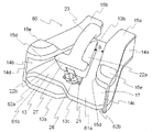
- FIG. 1 is a perspective view of a slider (10) according to the present embodiment.
- the slider (10) according to the present embodiment has, as a basic structure, a lower wing plate (13) and left and right erected along the left and right side edges of the lower wing plate (13).
- the first flange is also expressed as an upper blade.
- the Y-shaped space becomes an element guide passage (17) through which the fastener element attached to the fastener stringer passes.
- a pair of fastener stringers with the meshing heads (45) of the fastener elements facing each other is inserted from the shoulder opening of the slider (10), and the slider (10) is moved forward so that the left and right fastener elements are engaged.
- the slider (10) In the state (closed state), the slider (10) is pulled out from the rear opening.
- the folded portion of the fastener tape extends outward from the gap S between the first flange (15a, 15b) and the second flange (22a).
- the lower wing plate (13) has a substantially trapezoidal plate shape, and the width in the left-right direction is gradually reduced from the front end edge (13a) on the shoulder opening side to the position of about 3/4 of the full length, and then the rear wing plate (13). It is substantially the same up to the end edge (13b).
- the upper surface of the lower wing plate (13) is formed in parallel with the lower surfaces of the first flanges (15a, 15b).
- the ridge part inside the upper surface is chamfered.
- the first flange (15a, 15b) has a curved portion (15d) formed by rounding the inner corner of the front end of the shoulder opening.
- the fastener element can be smoothly drawn into the element guide passage (17). This also contributes to reducing the sliding resistance of the slider (10).
- a thickened portion (15e) is formed on the upper surface of the first flange (15a, 15b) on the shoulder opening side.
- the contact pressure acting on the fastener tape when contacting the thick part (15e) is low due to the large thickness part (15e) (that is, the contact area is large), The sliding resistance of the slider (10) is reduced and tearing of the fastener tape is prevented.
- the guide column (21) is formed in the shape of a substantially isosceles triangular column with the shoulder side being the bottom.
- left and right first flanges (15a, 15b) and a second flange (22a) having a substantially isosceles triangle shape extending toward the rear mouth and having a shoulder side at the bottom are provided on the guide column (21).
- left and right side surfaces of the second flange (22a) and the inner side surfaces of the first flanges (15a, 15b) are substantially parallel to each other, and a substantially constant gap S is formed between them. Extend from S.
- the upper surface on the shoulder opening side of the second flange (22a) has a thicker portion (15e) that is thicker than the thick portion (15e) formed on the upper surface on the shoulder opening side of the first flange (15a, 15b). 22b) is formed.
- the thickness of the thick part (22b) is maintained up to the front end of the second flange (22a) on the shoulder opening side, and the end surface (27) on the shoulder opening side of the second flange (22a) goes upward from the guide column (21).
- a high inclined wall projecting forward is formed.
- the fastener element inserted from the shoulder is initially raised by a strong lateral pulling force, it can enter the element guide passage (17) while smoothly tilting by the inclined wall.
- the element guide passage (17) can be moved in a state substantially parallel to the lower blade (13).
- FIG. 3 shows a state in which the handle (25) represented by a dotted line is attached to the handle attachment portion (23).
- the slider (10) according to the present embodiment is composed of two parts except for the handle (25), and each part can be manufactured by die casting or injection molding using a mold. By using two parts, it is possible to produce even a complicated structure that cannot be produced by the restrictions imposed by the mold structure with a conventional slider that is integrally molded. For example, by using two parts, the degree of freedom of the shape of the second flange (22a) is increased, and the second flange (22a) having a large lateral protrusion can be obtained. Specifically, the distance from the left and right center lines of the slider (10) to the left and right outermost ends of the second flange (22a) is the distance between the left and right center lines of the slider (10) and the side walls (14a and 14b).
- the distance to the inner surface on the mouth side can be 0.8 times or more, preferably 1.0 times or more. For this reason, the fastener element can be guided by the second flange (22a) and pulled in with a certain relatively weak force, and the slider (10) can be smoothly moved even if a strong lateral pulling force is applied when the slide fastener is closed. A sliding operation can be performed.
- FIG. 2 is an exploded perspective view of the slider (10) according to the present embodiment.
- the slider (10) according to this embodiment includes a slider body (11) having a lower wing plate (13), left and right side walls (14a, 14b), and first left and right flanges (15a, 15b), and a second body. It has a flange (22a) and is composed of two parts: a slider upper plate (12) engaged with the slider body (11).
- the guide column (21) and the handle attachment portion (23) are provided on the slider upper plate portion (12), which are the slider body (11) and the slider upper plate portion. It may be provided in any of (12).
- the overhanging portion (16) is erected at the left and right central portions of the lower wing plate (13) near the shoulder opening, while the upper plate portion (12) is provided with a guide column (21).
- a groove portion (24) having a rectangular opening extending at the left and right center portions of the shoulder mouth side end surface and the shoulder mouth side end surface (27) of the second flange (22a), and having a shape matching the shape of the overhang portion (16) Is provided.
- a pair of leg portions (26) project from the front end portions of the left and right side walls of the guide pillar (21) on the left and right of the opening of the groove portion (24) on the upper plate portion (12). ing.
- the slider body portion (11) and the upper plate portion (12) are united.
- the method for engaging the two parts is not particularly limited as long as the two parts are not easily separated.
- the slider body (11) and the upper plate (12) are engaged by the following method. Unite.
- the overhanging portion (16) is provided on the base along the shape of the base (16a) having a substantially T shape in plan view and extending in the left-right direction and the rear opening side, and along the shape of the base (16a).
- Standing part (16b) having a substantially T-shape in plan view that is narrower than (16a) and a substantially T-shape in standing on the standing part (16b) and having a width wider than that of the standing part (16b)
- the rib (16c) The end surface on the shoulder opening side of the rib (16c) is an overhanging inclined surface so that it becomes a surface with the end surface (27) on the shoulder opening side of the second flange (22a) after engagement with the upper plate portion (12). ing.
- the groove (24) has an internal structure that matches the shape of the overhanging portion (16) so that it can be engaged with the overhanging portion (16), and from the rear of the overhanging portion (16) to the front.
- the groove portion (24) By sliding the groove portion (24), the groove portion (24) and the overhang portion (16) are engaged. Thereafter, the overhanging portion (16) is fixed to the groove portion (24) by crimping the pair of leg portions (26) inward so that the opening of the groove portion (24) is sealed.
- FIG. 3 shows the engaged state of the projecting portion (16) and the groove portion (24).
- the front end surface (13c) of the lower wing plate (13) has a canceling relationship between the left and right shapes.
- the front end surface (13c) has a base surface (13d) formed substantially flush with the front end portions (14c, 14d) of the left and right side walls.
- the base surface (13d) has a flat surface in which the left and right side walls are linearly connected along the left-right direction.
- the front end surface (13c) has a locking plate (31) projecting forward from the base surface (13d) on the left half with the horizontal center as a boundary, and a recess on the base surface (13d) on the right half on the opposite side. And a receiving portion (32) matching the shape of the locking plate (31).
- the base surface (13d) defines the boundary between the locking plate (31, 61a, 61b, 71) and the receiving portion (32, 62a, 62b, 72).
- the locking plate (31) is thinner than the lower wing plate (13), the upper surface of the locking plate (31) is lower than the upper surface of the lower wing plate (13), and the lower surface of the locking plate (31) is It exists in a position higher than the lower surface of a lower blade (13). Further, the upper surface of the receiving portion (32) corresponding to this is lower than the upper surface of the lower wing plate (13), and the lower surface of the receiving portion (32) is formed at a position higher than the lower surface of the lower wing plate (13). It has a groove shape. As a result, when the front end surface (13c) of the lower wing plate (13) is in close contact with the front end surface of the lower wing plate of the counterpart slider, an overlap occurs in the vertical direction.
- the locking plate (31) and the receiving portion (32) are formed lower than the upper surface of the lower wing plate (13), the locking plate (31) and the receiving portion (32) are the element guide paths. Since it will be difficult to contact the element that is inserted through the slider, it will not interfere with the sliding of the slider.
- the locking plate (31) has a substantially trapezoidal shape in which the left and right widths gradually narrow toward the front. As a result, even when the sliders (10) facing each other are approached and the fastener is closed, even if the positions of the two are slightly shifted vertically and horizontally, the engagement of the locking plate (31) and the receiving portion (32) As the match progresses, it is naturally corrected to the correct position and a close state is obtained.
- the locking plate (31) is preferably chamfered.
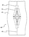
- FIG. 4 is a top view of the head-to-head type electromagnetic wave shield fastener (40) provided with the slider (10) according to the present embodiment as seen from above.
- the fastener tape (42) has a bent portion (43) on one side edge, and a plurality of fastener elements (41) are attached along the bent portion (43).
- a state in which a row of fastener elements (41) is attached to a fastener tape (42) is called a fastener stringer.
- the fastener tape (42) used in this embodiment includes a conductive material in the fastener tape, and the fastener stringer used in this example is the same as that of Example 1 of PCT / JP2009 / 059586. It can be as described.
- the edge of the fastener tape (42) is hidden behind and is not visible. In the figure, the part represented by the two-dot chain line indicates that it is hidden below.
- the handle (25) is indicated by a dotted line.
- FIG. 5 is a view of the electromagnetic shield hidden slide fastener (40) provided with the slider (10) according to the present embodiment, as viewed from above, in which the fastener is completely closed, and FIG. It is the figure seen from. 7 is a cross-sectional view taken along the line A-A 'of FIG. 6, and FIG. 8 is a cross-sectional view taken along the line B-B' of FIG.
- FIGS. 5 and 6 it can be seen that when the fasteners are completely closed, the rows of fastener elements (41) are hidden below, so that they cannot be seen from above. At this time, the bent portion of the fastener tape has a gap between one bent portion and the other bent portion due to a bulge portion (not shown) protruding from the engaging leg portion (44) of the element. The electromagnetic wave leakage from the part is blocked. 7 and 8, it can be seen that when the heads of the two sliders (10) are in contact with each other, the front end faces (13c) of the lower blade (13) are in close contact with each other. Referring to FIG. 8, it can be seen that the front end faces (13c) of the lower wing plate (13) overlap in the vertical direction.
- the front end portions (14c, 14d) of the left and right side walls (14a, 14b) are perpendicular to the front-rear direction, and the base surfaces of the front end surfaces (13c) of the two sliders (10).
- the front end portions (14c, 14d) of the left and right side walls (14a, 14b) are also in contact with each other.
- the foremost ends of the end surface (27) on the shoulder opening side of the second flange (22a) are also in close contact with each other. In this way, not only the lower wing plate (13) but also other portions of the slider head can be brought into close contact with each other, so that the electromagnetic wave shielding effect can be further improved.
- the base surface (13d) of the slider according to the present embodiment is the inner side of the front end portion (14c, 14d) of the side wall, the front end surface of the first flange (15a, 15b), and the front end surface of the second flange (22a). It is preferable that the most projecting part and the part projecting forward are more forward than the part projecting forward.
- the front end surfaces (13c) of the lower wing plate (13) are preferably connected to each other regardless of the shapes of the front end portions (14c, 14d) of the side walls, and the front end surfaces of the first flange and the second flange. Can be intimate.
- the base surface (13d) of the slider is formed so that the front end portions (14c, 14d) of the side walls and the front end surfaces of the first flange and the second flange are all in the same position.
- the front end portions (14c, 14d) of the left and right side walls (14a, 14b), the front end surfaces of the first flanges (15a, 15b), and the front end surfaces of the second flanges (22a) are the front end surfaces of the lower wing plate (13).
- the close state may be achieved by the uneven shape having a canceling relationship on the left and right.
- the front end portions (14c, 14d) of the side wall, the first flange so as not to disturb the close contact between the front end surfaces (13c) of the lower wing plate (13).
- At least one of the front end face of (15a, 15b) and the front end face of the second flange (22a) can be formed in any shape that fits between the sliders.
- the base surface (13d) necessarily protrudes most forward among the front end portions (14c, 14d) of the side wall, the front end surface of the first flange (15a, 15b), and the front end surface of the second flange (22a). It is not necessary to protrude to the front side of the place where it is placed.
- FIG. 9 is a perspective view of the slider (50) according to the present embodiment.
- the same components as those in the first embodiment are denoted by the same reference numerals, and the structure and function are described, and thus the description thereof is omitted. The same applies to the following embodiments.
- the second embodiment differs from the first embodiment in the shape of the front end face (13c) of the lower blade (13).
- the front end surface (13c) of the lower blade (13) is a flat surface perpendicular to the front-rear direction.
- the front end surface (13c) has no unevenness, that is, it consists only of the base surface (13d), but the front end surface (13c) of the lower wing plate (13) has a canceling relationship between the left and right shapes,
- the front end portions (14c, 14d) of the left and right side walls (14a, 14b) are flush with the front end surface (13c) of the lower wing plate (13), and the heads of the two sliders (50) are in contact with each other.
- the front end portions (14c, 14d) of the left and right side walls (14a, 14b) can be in close contact with each other.
- FIG. 10 is a perspective view of the slider (60) according to the present embodiment.
- the front end surface (13c) of the lower wing plate (13) has a canceling relationship between the left and right shapes, and the heads of two sliders (60) having the same shape Can be brought into close contact with each other when the fastener is completely closed and the lower wing plate (13) of the slider (60) is closed.
- the specific shape is different from that of the first embodiment and will be described below.
- the front end surface (13c) of the lower wing plate (13) has two steps of locking plates (61a, 61b) and receiving portions (62a, 62b).
- the front end surface (13c) of the lower wing plate (13) has two pairs of locking plates and receiving portions.
- the upper half of the front end surface (13c) is provided with a locking plate (61a) projecting forward over the left half and recessed rearward over the right half.
- a receiving portion (62a) matching the shape of the stop plate (61a) is formed.
- the lower half of the front end surface (13c) has a locking plate (61b) projecting forward over the right half thereof, and is recessed rearward over the left half of the locking plate.
- a receiving portion (62b) matching the shape of (61b) is formed.
- the upper surface of the upper locking plate (61a) is flush with the upper surface of the lower blade (13), and the lower surface of the lower locking plate (61b) is flush with the lower surface of the lower blade (13). is there.
- the locking plates (61a, 61b) have a substantially trapezoidal shape in which the left and right widths gradually narrow toward the front, and the advantages thereof are as described in the first embodiment.
- the front end portions (14c, 14d) of the left and right side walls (14a, 14b) and the foremost end of the shoulder surface side end surface (27) of the second flange (22a) can be closely contacted as in the first embodiment. Since the description is also given in the first embodiment, it will be omitted.
- FIG. 11 is a perspective view of the slider (70) according to the present embodiment.
- the front end surface (13c) of the lower wing plate (13) has a canceling relationship between the left and right shapes, and the heads of two sliders (70) having the same shape Can be brought into close contact with each other when the fasteners are completely closed and the lower wing plate (13) of the slider (70) is closed.
- the specific shape is different from that of the first embodiment and will be described below.
- the front end surface (13c) of the lower wing plate (13) is similar to the first embodiment in that it has a pair of locking plates (71) and receiving portions (72).
- the upper surface of the locking plate (71) protruding forward over the left half is on the same plane as the upper surface of the lower wing plate (13), and the lower surface of the locking plate (71) is the lower wing. It is in the same plane as the lower surface of the plate (13).
- a receiving portion (72) that matches the shape of the locking plate (71) is recessed rearward in the right half.
- FIG. 12 is a view of the slider (70) according to the present embodiment, as seen from below, in which the two sliders (70) facing each other are in close contact with each other. The left side is close front and the right side is close back.
- the locking plate (71) has a substantially trapezoidal shape in which the left and right widths gradually narrow toward the front, and the advantages thereof are as described in the first embodiment.
- the front end portions (14c, 14d) of the left and right side walls (14a, 14b) and the foremost end of the shoulder surface side end surface (27) of the second flange (22a) can be closely contacted as in the first embodiment. Since the description is also given in the first embodiment, it will be omitted.
- the front end surface (13c) of the lower wing plate (13) is related to the slider in which the left and right shapes are in a canceling relationship, but is not limited thereto.
- the slider is provided with a locking plate projecting from the base surface (13d), and the other slider is provided with a receiving portion (32) that matches the shape of the locking plate (31). It is good also as a structure which shields.
- the present invention is a hidden slide fastener
- the main purpose is not to use the slider so that it cannot be seen from the outside, but to shield electromagnetic waves by attaching a pair of fastener tapes together. It is used as the main purpose. Therefore, it is not always necessary to dispose the slider of the present invention so that it cannot be seen from the outside.
- the surface (the back surface of the fastener tape) on which the element is exposed can be used as the outside.
- a pull attachment part it is not limited to these, It can attach to arbitrary practical places.
- Electromagnetic shield fastener slider 11 Slider body 12 Upper plate portion 13 Lower wing plate 13a Front end edge 13b Rear end edge 13c Front end surface 13d Base surface 14a, 14b Side walls 14c, 14d Front end portions 15a, 15b First 1 flange (upper blade) 15d Curved part 15e Thick part 16 of the first flange 16 Overhang part 16a Base 16b Standing part 16c Rib 17 Element guide passage 21 Guide pillar 22a Second flange 22b Thick part 23 of the second flange 23 Pull handle attachment part 24 Groove part 25 Pull handle 26 Leg Portion 27 End surface 31, 61a, 61b, 71 on the shoulder side of the second flange Locking plate 32, 62a, 62b, 72 Receiving portion 40 Electromagnetic wave shield fastener 41 Fastener element 42 Fastener tape 43 Bending portion 44 Engagement leg portion 45 Engagement head portion
Landscapes
- Slide Fasteners (AREA)
Abstract
Description
なお本説明をもって本発明にPCT/JP2009/059586号の内容は参照によって組み込まれる。
そのようなスライダーは導電性を有する金属や合成樹脂を使用してダイキャスト成形や射出成形することによって製造することができる。導電性を有する金属としては、ファスナーテープと同様に金、銀、同、アルミニウム、タングステン、ニッケル、亜鉛、鉄又はこれらの一種以上を含有する金属が挙げられ、導電性を有する合成樹脂としては、トリアセチレン、ポリピロール、ポリチオフェン又はポリアニン等のようなものが挙げられる。また樹脂などの他の材料を使用してスライダーを成形した後に、上記金属でめっきすることも可能である。後述するように、複雑な形状のスライダーは複数の部品から組み立ててもよい。
本発明の第1実施形態に係る電磁波シールドファスナー用スライダー(10)について説明する。図1は、本実施形態に係るスライダー(10)の斜視図である。図1を参照すると、本実施形態に係るスライダー(10)は基本構造として、下翼板(13)と、該下翼板(13)の左右方向の側縁に沿って立設された左右の側壁(14a、14b)と、該左右の側壁(14a、14b)の上端から互いに接近する方向に延設された左右の第1フランジ(15a、15b)と、前記下翼板(13)の肩口寄り左右中央部から後口に向けて前記左右の第1フランジ(15a、15b)間に配置された案内柱(21)と、該案内柱(21)の上面に設けられ、少なくとも前記左右の第1フランジ(15a、15b)及び前記後口に向けて張り出した第2フランジ(22a)と、引手(25)を支持するための片持ち状の引手取付部(23)とを備える。なお、本発明においては第1フランジを上翼板とも表現している。
次に、本発明の第2実施形態に係る電磁波シールドファスナー用スライダー(50)について説明する。図9は、本実施形態に係るスライダー(50)の斜視図である。第1実施形態と同一の構成要素については、同一の符号が付されており、その構造や機能は記述しているので、説明は省略する。以降の実施形態についても同様である。
次に、本発明の第3実施形態に係る電磁波シールドファスナー用スライダー(60)について説明する。図10は、本実施形態に係るスライダー(60)の斜視図である。第3実施形態においても、第1実施形態と同様に、下翼板(13)の前端面(13c)は左右の形状が相殺関係にあり、同一形状の二つのスライダー(60)の頭部同士を当接させてファスナーを完全に閉じた状態の時に、スライダー(60)の下翼板(13)の前端面(13c)同士が密接することができる。但し、その具体的な形状が第1実施形態と異なるので以下に説明する。
次に、本発明の第4実施形態に係る電磁波シールドファスナー用スライダー(70)について説明する。図11は、本実施形態に係るスライダー(70)の斜視図である。第4実施形態においても、第1実施形態と同様に、下翼板(13)の前端面(13c)は左右の形状は相殺関係にあり、同一形状の二つのスライダー(70)の頭部同士を当接させてファスナーを完全に閉じた状態の時に、スライダー(70)の下翼板(13)の前端面(13c)同士が密接することができる。但し、その具体的な形状が第1実施形態と異なるので以下に説明する。
また、本発明は隠しスライドファスナーであるが、スライダーを外部から見えないようにして使用することを主たる目的としていくのではなく、対となるファスナーテープ同士を付き合わせることで電磁波を遮断させることを主たる目的として使用している。よって、必ずしも本発明のスライダーを外部から見えないように配置する必要はなく例えば、エレメントが露呈する面(ファスナーテープ裏面)を外側として使用することもできる。その際は、下翼板(13)の下面に引手取付部を設けて引手を取り付けることが好ましい。なお、引手取付部についてはこれらに限定されるものではなく、任意の実用的な箇所に取り付けることができる。
11 スライダー胴部
12 上板部
13 下翼板
13a 前端縁
13b 後端縁
13c 前端面
13d 基面
14a、14b 側壁
14c、14d 前端部
15a、15b 第1フランジ(上翼板)
15d 湾曲部
15e 第1フランジの肉厚部
16 張り出し部
16a 土台
16b 起立部
16c リブ
17 エレメント案内通路
21 案内柱
22a 第2フランジ
22b 第2フランジの肉厚部
23 引手取付部
24 溝部
25 引手
26 脚部
27 第2フランジの肩口側の端面
31、61a、61b、71 係止板
32、62a、62b、72 受容部
40 電磁波シールドファスナー
41 ファスナーエレメント
42 ファスナーテープ
43 屈曲部
44 噛合脚部
45 噛合頭部
Claims (10)
- 電磁波シールド特性を有し、一側縁に屈曲部(43)を有するファスナーテープ(42)と、当該屈曲部(43)に沿って取着されたファスナーエレメント(41)とを有する一対のファスナーストリンガーと、
前記一対のファスナーストリンガーに摺動自在に取り付けられ、各ファスナーエレメント(41)を係脱するための一対のスライダー(10、50、60、70)とを備えた隠しスライドファスナーであり、
当該一対のスライダー(10、50、60、70)はそれぞれ電磁波シールド特性を有しており、
下翼板(13)と、
該下翼板(13)の左右方向の側縁に沿って立設された左右の側壁(14a、14b)と、
該左右の側壁(14a、14b)の上端から互いに接近する方向に延設された左右の第1フランジ(15a、15b)と、
前記下翼板(13)の前記左右の第1フランジ(15a、15b)間に配置された案内柱(21)と、
該案内柱(21)に設けられ少なくとも後口に向けて張り出した第2フランジ(22a)と、
該下翼板(13)と、左右の該側壁(14a)と該第1フランジ(15a、15b)に囲まれたファスナーエレメト(41)を案内するエレメント案内通路(17)と、
前記第1フランジ(15a、15b)及び前記第2フランジ(22a)間に、ファスナーテープ(42)の一部が該エレメント案内通路(17)から外側に延出可能な隙間Sと、
を備え、
前記一対のスライダーは肩口側同士が対向するようにファスナーストリンガーに取り付けられ、
一方のスライダーの下翼板(13)の前端面(13c)は、他方のスライダーの下翼板の前端面に密接可能な形状に形成されている隠しスライドファスナー。 - 一方のスライダーの下翼板(13)の前端面(13c)は、前記左右の第1フランジ間(15a、15b)において他方のスライダーの下翼板の前端面と密接可能である請求項1に記載の隠しスライドファスナー。
- 一方のスライダーの下翼板(13)の前端面(13c)は、他方のスライダーの下翼板の前端面と同一形状を有しており、左右の形状が相殺関係にある請求項1又は2に記載の隠しスライドファスナー。
- 一方のスライダーの下翼板(13)の前端面(13c)は、他方のスライダーの下翼板の前端面と密接したときに上下方向に重なりが生じるように、凹凸形状を有する請求項1~3の何れか一項に記載の隠しスライドファスナー。
- 各スライダーの下翼板(13)の前端面(13c)は、左半分及び右半分の何れか一方に亘って前方に凸設された係止板(31、61a、61b、71)と、左半分及び右半分の他方に亘って後方に凹設され、前記係止板(31、61a、61b、71)の形状に合致した受容部(32、62a、62b、72)とを少なくとも一対有する請求項1~4の何れか一項に記載の隠しスライドファスナー。
- 各スライダーの前記係止板(31、61a、61b、71)は下翼板(13)よりも薄く、前記係止板(31、61a、61b、71)の上面は下翼板(13)の上面よりも低い位置にあり、前記係止板(31、61a、61b、71)の下面は下翼板(13)の下面よりも高い位置にあり、前記受容部(32、62a、62b、72)は前記係止板(31、61a、61b、71)の形状に合致した溝状となっている請求項5に記載の隠しスライドファスナー。
- 各スライダーの前記下翼板(13)の前端面(13c)は、左右の側壁(14a、14b)の前端部(14c、14d)と同一面上にある基面(13d)を備えており、前記基面(13d)から前記係止板(31、61a、61b、71)及び前記受容部(32、62a、62b、72)が形成されている請求項5に記載の隠しスライドファスナー。
- 一方のスライダーの前記左右の側壁(14a、14b)の前端部(14c、14d)は、他方のスライダーの対応する側壁のそれぞれの前端部と密接可能な形状に形成されている請求項1~7の何れか一項に記載の隠しスライドファスナー。
- 各スライダーの下翼板(13)の前端面(13c)は、前記係止板(31、61a、61b、71)及び受容部(32、62a、62b、72)の境界を規定する基面(13d)を有しており、当該基面(13d)は、側壁の前端部(14c、14d)、第1フランジ(15a、15b)の前端面及び第2フランジ(22a)の前端面の内で最も前方に突出している箇所と同位置かそれよりも前方側に突出している請求項5に記載の隠しスライドファスナー。
- スライダー(10、50、60、70)は前記下翼板(13)、前記左右の側壁(14a、14b)、及び前記左右の第1フランジ(15a、15b)を有するスライダー胴部(11)と、前記第2フランジ(22a)を有し、当該スライダー胴部(11)に係合されるスライダー上板部(12)との少なくとも2部品で構成されており、前記案内柱(21)は前記スライダー胴部(11)及び前記スライダー上板部(12)の何れかに設けられる請求項1~9の何れか一項に記載の隠しスライドファスナー。
Priority Applications (4)
| Application Number | Priority Date | Filing Date | Title |
|---|---|---|---|
| CN201080068807.9A CN103068271B (zh) | 2010-11-25 | 2010-11-25 | 隐形拉链 |
| JP2012545574A JP5735002B2 (ja) | 2010-11-25 | 2010-11-25 | 隠しスライドファスナー |
| PCT/JP2010/071045 WO2012070136A1 (ja) | 2010-11-25 | 2010-11-25 | 隠しスライドファスナー |
| TW100107971A TWI418316B (zh) | 2010-11-25 | 2011-03-09 | Hidden zipper |
Applications Claiming Priority (1)
| Application Number | Priority Date | Filing Date | Title |
|---|---|---|---|
| PCT/JP2010/071045 WO2012070136A1 (ja) | 2010-11-25 | 2010-11-25 | 隠しスライドファスナー |
Publications (1)
| Publication Number | Publication Date |
|---|---|
| WO2012070136A1 true WO2012070136A1 (ja) | 2012-05-31 |
Family
ID=46145513
Family Applications (1)
| Application Number | Title | Priority Date | Filing Date |
|---|---|---|---|
| PCT/JP2010/071045 Ceased WO2012070136A1 (ja) | 2010-11-25 | 2010-11-25 | 隠しスライドファスナー |
Country Status (4)
| Country | Link |
|---|---|
| JP (1) | JP5735002B2 (ja) |
| CN (1) | CN103068271B (ja) |
| TW (1) | TWI418316B (ja) |
| WO (1) | WO2012070136A1 (ja) |
Cited By (1)
| Publication number | Priority date | Publication date | Assignee | Title |
|---|---|---|---|---|
| WO2015097793A1 (ja) * | 2013-12-25 | 2015-07-02 | Ykk株式会社 | スライドファスナー用スライダー、及びスライドファスナー |
Families Citing this family (7)
| Publication number | Priority date | Publication date | Assignee | Title |
|---|---|---|---|---|
| CN105124866B (zh) * | 2015-09-30 | 2017-06-16 | 开易(广东)服装配件有限公司 | 隐形拉链用拉头 |
| CN106274417B (zh) * | 2016-09-07 | 2019-01-04 | 南京康尼机电股份有限公司 | 一种用于将胶条配合部装配到型材配合槽中的拉链头 |
| FR3055529B1 (fr) * | 2016-09-07 | 2018-08-24 | Genius Objects | Dispositif a fermeture a glissiere comprenant un curseur electriquement conducteur |
| CN107136668B (zh) * | 2017-06-30 | 2022-02-08 | 福建浔兴拉链科技股份有限公司 | 一种拉链拉头及隐形拉链 |
| CN109924614A (zh) * | 2019-04-25 | 2019-06-25 | 周士志 | 一种新型拉链组件 |
| CN111602934B (zh) * | 2020-05-22 | 2021-10-15 | 福建浔兴拉链科技股份有限公司 | 一种快速分离拉链 |
| CN117770584A (zh) * | 2023-12-25 | 2024-03-29 | 晋江福兴拉链有限公司 | 用于隐形拉链的拉头及拉链 |
Citations (4)
| Publication number | Priority date | Publication date | Assignee | Title |
|---|---|---|---|---|
| JPS468411Y1 (ja) * | 1967-04-28 | 1971-03-25 | ||
| JP2004016688A (ja) * | 2002-06-20 | 2004-01-22 | Ykk Corp | スライドファスナー |
| WO2009093678A1 (ja) * | 2008-01-25 | 2009-07-30 | Matsuyama Keori Co., Ltd. | 電磁波シールド用ファスナー及びこのファスナーを用いた電磁波シールド体 |
| WO2010137111A1 (ja) * | 2009-05-26 | 2010-12-02 | Ykk株式会社 | ファスナーストリンガー及びスライドファスナー、並びにファスナー被着物 |
Family Cites Families (5)
| Publication number | Priority date | Publication date | Assignee | Title |
|---|---|---|---|---|
| US2621387A (en) * | 1946-02-01 | 1952-12-16 | Harvey L Williams | Slide fastener |
| AT305927B (de) * | 1968-01-15 | 1973-03-26 | Susanne Vorsteher | Reißverschluß |
| JPS5646566Y2 (ja) * | 1977-03-14 | 1981-10-30 | ||
| JP4307356B2 (ja) * | 2004-10-07 | 2009-08-05 | Ykk株式会社 | 自動停止装置付スライドファスナー用スライダー |
| GB0711636D0 (en) * | 2007-06-15 | 2007-07-25 | D G Capital Ltd | Zip closure system |
-
2010
- 2010-11-25 WO PCT/JP2010/071045 patent/WO2012070136A1/ja not_active Ceased
- 2010-11-25 CN CN201080068807.9A patent/CN103068271B/zh active Active
- 2010-11-25 JP JP2012545574A patent/JP5735002B2/ja active Active
-
2011
- 2011-03-09 TW TW100107971A patent/TWI418316B/zh active
Patent Citations (4)
| Publication number | Priority date | Publication date | Assignee | Title |
|---|---|---|---|---|
| JPS468411Y1 (ja) * | 1967-04-28 | 1971-03-25 | ||
| JP2004016688A (ja) * | 2002-06-20 | 2004-01-22 | Ykk Corp | スライドファスナー |
| WO2009093678A1 (ja) * | 2008-01-25 | 2009-07-30 | Matsuyama Keori Co., Ltd. | 電磁波シールド用ファスナー及びこのファスナーを用いた電磁波シールド体 |
| WO2010137111A1 (ja) * | 2009-05-26 | 2010-12-02 | Ykk株式会社 | ファスナーストリンガー及びスライドファスナー、並びにファスナー被着物 |
Cited By (3)
| Publication number | Priority date | Publication date | Assignee | Title |
|---|---|---|---|---|
| WO2015097793A1 (ja) * | 2013-12-25 | 2015-07-02 | Ykk株式会社 | スライドファスナー用スライダー、及びスライドファスナー |
| JPWO2015097793A1 (ja) * | 2013-12-25 | 2017-03-23 | Ykk株式会社 | スライドファスナー用スライダー、及びスライドファスナー |
| US9750313B2 (en) | 2013-12-25 | 2017-09-05 | Ykk Corporation | Slider for slide fastener, and slide fastener |
Also Published As
| Publication number | Publication date |
|---|---|
| TW201221080A (en) | 2012-06-01 |
| TWI418316B (zh) | 2013-12-11 |
| CN103068271A (zh) | 2013-04-24 |
| JP5735002B2 (ja) | 2015-06-17 |
| CN103068271B (zh) | 2015-09-02 |
| JPWO2012070136A1 (ja) | 2014-05-19 |
Similar Documents
| Publication | Publication Date | Title |
|---|---|---|
| JP5735002B2 (ja) | 隠しスライドファスナー | |
| KR101558070B1 (ko) | 간이 로크 기구를 갖는 슬라이드 파스너 및 슬라이더 | |
| US8539650B2 (en) | Slide fastener | |
| US9763498B2 (en) | Slider cover for slide fastener and slide fastener with slide cover | |
| KR100983163B1 (ko) | 슬라이드 파스너용 상부 고정부 | |
| CN106714609B (zh) | 拉链链牙、拉链牙链带及拉链 | |
| EP1913833A1 (en) | Reverse opening type separable end stop of slide fastener | |
| US8826500B2 (en) | Slide fastener | |
| US20150000087A1 (en) | Waterproof Slide Fastener | |
| EP2904922B1 (en) | Slide fastener | |
| JP2007097840A (ja) | 防水性スライドファスナー | |
| US20120124787A1 (en) | Slide Fastener | |
| JP2009022547A (ja) | スライドファスナー用スライダー | |
| JP4822187B2 (ja) | 隠しスライドファスナー | |
| JP2007236958A6 (ja) | 隠しスライドファスナー | |
| KR100517572B1 (ko) | 은폐형 슬라이드 파스너 | |
| JP5269194B2 (ja) | ファスナーストリンガー及びスライドファスナー、並びにファスナー被着物 | |
| WO2020230333A1 (ja) | スライドファスナー | |
| EP1459643B1 (en) | Slide fastener with separable bottom end stop | |
| CN1791340A (zh) | 整合的拉链头和防护装置 | |
| EP1745713A1 (en) | Slide fastener | |
| US12250999B2 (en) | Slide fastener elements, fastener stringers, and fastener chain | |
| JP2021069822A (ja) | 防水性スライドファスナーのスライダー及び防水性スライドファスナー | |
| WO2014188581A1 (ja) | スライドファスナー | |
| CN211532974U (zh) | 一种防辐射拉链 |
Legal Events
| Date | Code | Title | Description |
|---|---|---|---|
| WWE | Wipo information: entry into national phase |
Ref document number: 201080068807.9 Country of ref document: CN |
|
| 121 | Ep: the epo has been informed by wipo that ep was designated in this application |
Ref document number: 10859937 Country of ref document: EP Kind code of ref document: A1 |
|
| WWE | Wipo information: entry into national phase |
Ref document number: 2012545574 Country of ref document: JP |
|
| NENP | Non-entry into the national phase |
Ref country code: DE |
|
| 122 | Ep: pct application non-entry in european phase |
Ref document number: 10859937 Country of ref document: EP Kind code of ref document: A1 |