WO2012064100A2 - 무선통신 시스템에서 전력상태보고를 전송하기 위한 방법 및 이를 위한 단말 장치 - Google Patents
무선통신 시스템에서 전력상태보고를 전송하기 위한 방법 및 이를 위한 단말 장치 Download PDFInfo
- Publication number
- WO2012064100A2 WO2012064100A2 PCT/KR2011/008505 KR2011008505W WO2012064100A2 WO 2012064100 A2 WO2012064100 A2 WO 2012064100A2 KR 2011008505 W KR2011008505 W KR 2011008505W WO 2012064100 A2 WO2012064100 A2 WO 2012064100A2
- Authority
- WO
- WIPO (PCT)
- Prior art keywords
- terminal
- base station
- value
- power
- offset
- Prior art date
Links
Images


Classifications
-
- H—ELECTRICITY
- H04—ELECTRIC COMMUNICATION TECHNIQUE
- H04W—WIRELESS COMMUNICATION NETWORKS
- H04W52/00—Power management, e.g. TPC [Transmission Power Control], power saving or power classes
- H04W52/04—TPC
- H04W52/06—TPC algorithms
- H04W52/16—Deriving transmission power values from another channel
-
- H—ELECTRICITY
- H04—ELECTRIC COMMUNICATION TECHNIQUE
- H04W—WIRELESS COMMUNICATION NETWORKS
- H04W52/00—Power management, e.g. TPC [Transmission Power Control], power saving or power classes
- H04W52/04—TPC
- H04W52/06—TPC algorithms
- H04W52/14—Separate analysis of uplink or downlink
- H04W52/146—Uplink power control
-
- H—ELECTRICITY
- H04—ELECTRIC COMMUNICATION TECHNIQUE
- H04W—WIRELESS COMMUNICATION NETWORKS
- H04W52/00—Power management, e.g. TPC [Transmission Power Control], power saving or power classes
- H04W52/04—TPC
- H04W52/18—TPC being performed according to specific parameters
- H04W52/24—TPC being performed according to specific parameters using SIR [Signal to Interference Ratio] or other wireless path parameters
- H04W52/241—TPC being performed according to specific parameters using SIR [Signal to Interference Ratio] or other wireless path parameters taking into account channel quality metrics, e.g. SIR, SNR, CIR, Eb/lo
-
- H—ELECTRICITY
- H04—ELECTRIC COMMUNICATION TECHNIQUE
- H04W—WIRELESS COMMUNICATION NETWORKS
- H04W24/00—Supervisory, monitoring or testing arrangements
- H04W24/10—Scheduling measurement reports ; Arrangements for measurement reports
-
- H—ELECTRICITY
- H04—ELECTRIC COMMUNICATION TECHNIQUE
- H04W—WIRELESS COMMUNICATION NETWORKS
- H04W52/00—Power management, e.g. TPC [Transmission Power Control], power saving or power classes
- H04W52/04—TPC
-
- H—ELECTRICITY
- H04—ELECTRIC COMMUNICATION TECHNIQUE
- H04W—WIRELESS COMMUNICATION NETWORKS
- H04W52/00—Power management, e.g. TPC [Transmission Power Control], power saving or power classes
- H04W52/04—TPC
- H04W52/18—TPC being performed according to specific parameters
-
- H—ELECTRICITY
- H04—ELECTRIC COMMUNICATION TECHNIQUE
- H04W—WIRELESS COMMUNICATION NETWORKS
- H04W52/00—Power management, e.g. TPC [Transmission Power Control], power saving or power classes
- H04W52/04—TPC
- H04W52/18—TPC being performed according to specific parameters
- H04W52/24—TPC being performed according to specific parameters using SIR [Signal to Interference Ratio] or other wireless path parameters
Definitions
- the present invention relates to wireless communication, and more particularly, to a method for transmitting a power status report and a terminal device therefor.
- the next generation multimedia wireless communication system which is being actively researched recently, needs to process various information such as video, wireless data, etc. at a higher data rate beyond the initial voice-oriented service.
- OFDM Orthogonal Frequency Division Multiplexing
- OFDM is a multi-carrier modulation technique that transmits data by dividing a frequency band into a plurality of orthogonal subcarriers, and can reduce inter-symbol interference effects with low complexity.
- OFDM converts serially input data symbols into N parallel data symbols and transmits them on N subcarriers, respectively.
- Orthogonal Frequency Division Multiple Access refers to a multiple access method for realizing multiple access by independently providing each user with a part of subcarriers available in a system using OFDM as a modulation scheme.
- OFDMA provides each user with a frequency resource called a subcarrier, and each frequency resource is provided to a plurality of users independently so that they do not overlap each other. Eventually, frequency resources are allocated mutually exclusively for each user.
- Frequency diversity scheduling for multiple users can be obtained through frequency selective scheduling of an OFDMA system, and subcarriers can be allocated in various forms according to a permutation scheme for subcarriers. .
- an uplink control channel through which a control signal is transmitted and an uplink data channel through which data is transmitted may be physically distinguished.
- Control / data channels can also be transmitted simultaneously. Transmission power of uplink transmission channels may be determined through a specific equation.
- the base station may receive a power state report (PSR) reporting from the terminal to perform the next scheduling of the terminal.
- PSR power state report
- FFR partial frequency reuse
- An object of the present invention is to provide a method for a terminal to transmit a power state report in a wireless communication system.
- Another object of the present invention is to provide a terminal device for transmitting a power status report in a wireless communication system.
- a method for transmitting a power state report in a wireless communication system includes receiving at least one of a data channel offset value and a control channel offset value for uplink power control from a base station. step; Determining a basic uplink transmission power level for at least one of the data channel and the control channel based on at least one of the received offset values of the data channel and the control channel; And transmitting the determined at least one basic uplink transmission power level to the base station, and calculating a downlink signal to interference power ratio value using the downlink signal received from the base station. It may include. The ratio of the downlink signal to the interference power measured by the terminal may be transmitted together with the at least one basic uplink transmit power level.
- the determined default uplink transmit power level may be a value corresponding to each carrier.
- the measured ratio of downlink signal to interference power may be measured for each fractional frequency reuse (FFR) partition index.
- the offset value used to determine the basic uplink transmission power level may be a value calculated by accumulating the data channel offset value received from the base station and the offset value for each control channel.
- the offset value accumulated by each data channel offset value and the control channel may be an offset value accumulated at the time of triggering the power state report.
- a terminal device for transmitting a power state report in a wireless communication system receives at least one of a data channel offset value and a control channel offset value for uplink power control from a base station.
- a receiver configured to determine a basic uplink transmission power level for at least one of the data channel and the control channel based on at least one of the received offset values of the data channel and the control channel;
- a transmitter for transmitting the determined at least one basic uplink transmission power level to the base station.
- the processor may calculate a downlink signal-to-interference power ratio value using the downlink signal received from the base station, and the transmitter may calculate the ratio of the downlink signal to interference power measured by the processor based on the at least one basic value.
- the determined default uplink transmit power level may be a value corresponding to each carrier.
- the measured ratio of downlink signal to interference power may be measured for each fractional frequency reuse (FFR) partition index.
- the offset value used by the processor to determine the basic uplink transmission power level may be a value calculated by accumulating data channel offset values received from the base station and offset values for respective control channels.
- FIG. 1 is a block diagram illustrating the configuration of a base station 105 and a terminal 110 in a wireless communication system 100.
- FIG. 2 is a diagram illustrating an example of a process for transmitting a power state report (PSR) of a terminal according to the present invention.
- PSR power state report
- a terminal collectively refers to a mobile or fixed user terminal device such as a user equipment (UE), a mobile station (MS), an advanced mobile station (AMS), and the like.
- the base station collectively refers to any node of the network side that communicates with the terminal such as a Node B, an eNode B, a Base Station, and an Access Point (AP).
- UE user equipment
- MS mobile station
- AMS advanced mobile station
- AP Access Point
- a user equipment may receive information from a base station through downlink, and the terminal may also transmit information through uplink.
- Information transmitted or received by the terminal includes data and various control information, and various physical channels exist according to the type and purpose of information transmitted or received by the terminal.
- FIG. 1 is a block diagram illustrating the configuration of a base station 105 and a terminal 110 in a wireless communication system 100.
- the wireless communication system 100 may include one or more base stations and / or one or more terminals. .
- the base station 105 includes a transmit (Tx) data processor 115, a symbol modulator 120, a transmitter 125, a transmit / receive antenna 130, a processor 180, a memory 185, and a receiver ( 190, a symbol demodulator 195, and a receive data processor 197.
- the terminal 110 transmits (Tx) the data processor 165, the symbol modulator 175, the transmitter 175, the transmit / receive antenna 135, the processor 155, the memory 160, the receiver 140, and the symbol. It may include a demodulator 155 and a receive data processor 150.
- the base station 105 and the terminal 110 are provided with a plurality of transmit and receive antennas. Accordingly, the base station 105 and the terminal 110 according to the present invention support a multiple input multiple output (MIMO) system. In addition, the base station 105 according to the present invention may support both a single user-MIMO (SU-MIMO) and a multi-user-MIMO (MU-MIMO) scheme.
- MIMO multiple input multiple output
- SU-MIMO single user-MIMO
- MU-MIMO multi-user-MIMO
- the transmit data processor 115 receives the traffic data, formats the received traffic data, codes it, interleaves and modulates (or symbol maps) the coded traffic data, and modulates the symbols ("data"). Symbols ").
- the symbol modulator 120 receives and processes these data symbols and pilot symbols to provide a stream of symbols.
- the symbol modulator 120 multiplexes the data and pilot symbols and sends it to the transmitter 125.
- each transmission symbol may be a data symbol, a pilot symbol, or a signal value of zero.
- pilot symbols may be sent continuously.
- the pilot symbols may be frequency division multiplexed (FDM), orthogonal frequency division multiplexed (OFDM), time division multiplexed (TDM), or code division multiplexed (CDM) symbols.
- Transmitter 125 receives the stream of symbols and converts it into one or more analog signals, and further adjusts (eg, amplifies, filters, and frequency upconverts) the analog signals to provide a wireless channel. Generates a downlink signal suitable for transmission via the transmission antenna 130, the transmission antenna 130 transmits the generated downlink signal to the terminal.
- the receiving antenna 135 receives the downlink signal from the base station and provides the received signal to the receiver 140.
- Receiver 140 adjusts the received signal (eg, filtering, amplifying, and frequency downconverting), and digitizes the adjusted signal to obtain samples.
- the symbol demodulator 145 demodulates the received pilot symbols and provides them to the processor 155 for channel estimation.
- the symbol demodulator 145 also receives a frequency response estimate for the downlink from the processor 155 and performs data demodulation on the received data symbols to obtain a data symbol estimate (which is an estimate of the transmitted data symbols). Obtain and provide data symbol estimates to a receive (Rx) data processor 150. Receive data processor 150 demodulates (ie, symbol de-maps), deinterleaves, and decodes the data symbol estimates to recover the transmitted traffic data.
- the processing by symbol demodulator 145 and receiving data processor 150 is complementary to the processing by symbol modulator 120 and transmitting data processor 115 at base station 105, respectively.
- the terminal 110 is on the uplink, and the transmit data processor 165 processes the traffic data to provide data symbols.
- the symbol modulator 170 may receive and multiplex data symbols, perform modulation, and provide a stream of symbols to the transmitter 175.
- the transmitter 175 receives and processes a stream of symbols to generate an uplink signal.
- the transmit antenna 135 transmits the generated uplink signal to the base station 105.
- an uplink signal is received from the terminal 110 through the reception antenna 130, and the receiver 190 processes the received uplink signal to obtain samples.
- the symbol demodulator 195 then processes these samples to provide received pilot symbols and data symbol estimates for the uplink.
- the received data processor 197 processes the data symbol estimates to recover the traffic data transmitted from the terminal 110.
- Processors 155 and 180 of the terminal 110 and the base station 105 respectively instruct (eg, control, coordinate, manage, etc.) operations at the terminal 110 and the base station 105, respectively.
- Respective processors 155 and 180 may be connected to memory units 160 and 185 that store program codes and data.
- the memory 160, 185 is coupled to the processor 180 to store the operating system, applications, and general files.
- the processors 155 and 280 may also be referred to as a controller, a microcontroller, a microprocessor, a microcomputer, or the like.
- the processors 155 and 180 may be implemented by hardware or firmware, software, or a combination thereof.
- ASICs application specific integrated circuits
- DSPs digital signal processors
- DSPDs digital signal processing devices
- PLDs programmable logic devices
- FPGAs Field programmable gate arrays
- the firmware or software may be configured to include a module, a procedure, or a function for performing the functions or operations of the present invention, and to perform the present invention.
- the firmware or software configured to be may be provided in the processors 155 and 180 or stored in the memory 160 and 185 to be driven by the processors 155 and 180.
- the layers of the air interface protocol between the terminal and the base station between the wireless communication system (network) are based on the lower three layers of the open system interconnection (OSI) model, which is well known in the communication system. ), And the third layer L3.
- the physical layer belongs to the first layer and provides an information transmission service through a physical channel.
- a Radio Resource Control (RRC) layer belongs to the third layer and provides control radio resources between the UE and the network.
- the terminal and the base station may exchange RRC messages through the wireless communication network and the RRC layer.
- Equation 1 In the IEEE 802.16m system, which is an example of a mobile communication system, a method of determining an uplink transmission power by a UE using Equation 1 will be briefly described. In general, the UE needs to determine an uplink transmission power value when transmitting an uplink signal.
- P represents a transmission power level (in dBm units) for each subcarrier and stream for the current transmission
- L represents a current average downlink propagation loss estimated by the terminal.
- L includes the transmit antenna gain and path loss of the terminal.
- SINR Target is a target uplink signal to interference plus noise ratio (SINR) value received from a base station.
- SINR is a target uplink signal to interference plus noise ratio (SINR) value received from a base station.
- NI is an average noise and interference level (in dBm) per subcarrier estimated by the base station, and is a value received by the terminal from the base station.
- Offset is a correction term for power offset for each terminal.
- the offset values are transmitted on the power control message from the base station, there are two types of offset values are present to offset used for data transmission in Offsetdata value, the control information, the offset value used for transmission Offsetcontrol.
- Equation 1 in the case of a control channel for transmitting control information, the terminal previously defines a target signal to noise and interference ratio (SINR) value corresponding to the control channel. Applicable immediately using Table 1.
- SINR target signal to noise and interference ratio
- SINR MIN (dB) is a minimum SINR value required by the base station and is a value set in a unicast power control message.
- SINR MIN is represented by 4 bits, the value of which is one of ⁇ - ⁇ , -3, -2.5, -1, 0, 0.5, 1, 1.5, 2, 2.5, 3, 3.5, 4, 4.5 ⁇ Can be the value of.
- SIR DL means a ratio of downlink signal to interference power measured by the terminal.
- ⁇ IoT is fairness and IoT control factor and the base station broadcasts to the terminal.
- Alpha ( ⁇ ) is a coefficient according to the number of receiving antennas at the base station and is signaled in 3 bits as MAC power control mode signaling, where the value is, for example, ⁇ 1, 1/2, 1/4, 1/8, 1 / 16, 0 ⁇ .
- Beta ( ⁇ ) may be set to 0 or 1 by 1 bit of MAC power control mode signaling.
- TNS is the total number of streams in the Logical Resource Unit (LRU) indicated by UL-A-MAP IE.
- LRU Logical Resource Unit
- Mt the number of streams per user.
- TNS the total number of streams.
- control channel transmission this value may be set to one.
- the two key parameters are base uplink transmission PSD and SIR DL .
- the basic uplink transmission PSD can be derived by setting the SINRtarget value and the offset value to 0 in Equation 1, which can be expressed as Equation 2 below.
- the PSD parameter is reported in units of dBm and is encoded using 8 bits in units of 0.5 dBm in a range of -74 dBm (coded 0x00) to 53.5 dBm (0xFF coded).
- the NI value used in Equation 3 is the most recent NI value of the frequency partition with the uplink control channel.
- the SIR DL value measured by the UE is coded using 10 bits in 1/16 dB units in a range from -12 dB (coded at 0x000) to 51/9375 dB (coded at 0x3ff).
- the processor 180 of the base station can estimate the PSD for all uplink channels.
- Equation 4 When the condition shown in Equation 4 is satisfied, the event is triggered and the terminal needs to transmit an uplink power state report message to the base station through the uplink power state report header.
- L denotes a transmission antenna gain and a path loss of the terminal shown in Equation (1).
- the SINR target is a value when ⁇ is 0 in Equation 2, and the SINR target is a measured value at the 'reported' moment.
- n last represents a frame index when the last terminal status report message is transmitted, and n represents a current frame index.
- status reporting configuration parameters. The base station is transmitted through the AAI-UL-PSR-CFG message to the terminal.
- the terminal should send the first power state report after receiving the first AAI-UL-PSR-CFG message with the uplinkPowerStateReport parameter set to 1.
- Table 2 below shows an uplink status report message in an IEEE 802.16m system as an example of a mobile communication system.
- Table 2 shows the state reporting configuration parameters of Equation 4. , , It explains.
- the UE in the AAI-UL-PSR-CFG message shown in Table 2 The parameter value may be reported to the base station.
- Table 3 below shows an uplink power state report header used to carry uplink power control state information of a terminal.
- Table 3 shows an uplink power state report header format for the UE to report the uplink power state.
- the uplink power state report header format includes a flow identifier, a MAC signaling header type, a length of a signaling header, an indicator indicating whether an uplink power control (ULPC) parameter has been updated, a configuration change count, txPowerPsdBase, txSirDownlink, and associated with this signaling header.
- ULPC uplink power control
- the uplink transmission power is allocated in the order of the control channel according to the priority of Table 4 until the total transmission power reaching the maximum power limit of the terminal. If the terminal does not have enough power to transmit the allocated channel, the terminal may transmit these channels according to the priority with the remaining power even if the power level determined by Equation 1 is not met. Table 4 below shows power allocation priorities among channels.
- types of transport channels may be generally classified into data channels for data transmission and control channels for control information transmission.
- uplink data has a chance of retransmission using link adaptation or hybrid automatic repeat reQuest (HARQ)
- HARQ hybrid automatic repeat reQuest
- the uplink data does not have a chance of retransmission because the HARQ is not performed on the uplink control signal. Therefore, it is necessary to make the control channel priority higher than the data channel.
- a terminal that does not receive an ACK (ACKnowledgement) signal of the bandwidth request from the base station performs a bandwidth request based on a random access (Random Access), use a bandwidth request signaling header, or piggybacked bandwidth request Or a bandwidth request using a fast feedback channel.
- the random access bandwidth request is made through the bandwidth request channel when there is no transmission of the feedback signal and the transmission of the data signal, and the bandwidth request signaling header is transmitted to the base station in response to receiving the acknowledgment of the bandwidth request header from the base station.
- the piggybacked bandwidth request is a method of transmitting the bandwidth request together with the data when there is data at the time of sending the bandwidth request.
- the bandwidth request may be transmitted by the terminal to the base station through the main fast feedback channel (PFBCH). Therefore, in Table 4, although the bandwidth request channel is a kind of control channel in principle, it has the lowest priority because there are many retransmission methods and opportunities.
- PFBCH main fast feedback channel
- the HARQ feedback channel which is a channel for transmitting an ACK (Acknowledgement) / NACK (Non-acknowledgement) signal, which is a response to the data transmission of the base station, transmits packet data by reducing a retransmission request from the terminal to the base station. Since the channel is essential for performing the HARQ operation to increase efficiency, it has the highest priority.
- PFBCH / SFBCH channel is used for transmission of Channel Quality Indicator (CQI), Space Timing Coding (STC) Speed Indicator, Precoding Matrix Index (PMI), etc., and is involved in downlink scheduling, downlink user selection, and resource allocation. Therefore, this may correspond to the priority following the HARQ feedback channel.
- CQI Channel Quality Indicator
- STC Space Timing Coding
- PMI Precoding Matrix Index
- the base station may not recognize the terminal, it may be unable to properly perform resource allocation and subsequent communication. Therefore, since a terminal once synchronized to a specific base station needs to perform a tracking to maintain synchronization by transmitting a periodic ranging signal, the ranging channel necessary for continuously maintaining synchronization between the terminal and the base station also has a higher priority.
- the sounding reference signal (or sounding signal) is a signal transmitted in a synchronized state, and the base station estimates an uplink channel state based on the sounding reference signal received from the terminal and schedules according to the estimated channel state. For example, user selection and resource allocation may be performed.
- the terminal In order for the terminal to stably transmit the sounding reference signal to the base station, the terminal must maintain synchronization with the base station, and thus the sounding channel through which the sounding reference signal is transmitted may have a lower priority than the synchronized ranging channel.
- the data may have a lower priority than the HARQ feedback channel, the PFBCH / SFBCH channel, the synchronized ranging channel, and the sounding channel.
- the base station can predict the expected transmit power level (expected transmit power level) for the data channel and the control channels. .
- the offset value must operate only with an absolute value.
- the control channel (s) and the data channel can be transmitted within the same time and / or resource interval, reporting information of such a terminal is necessary.
- the transmission power of the data channel is determined as the remaining power after the power allocation of the control channel. Therefore, the power information of the control channel considering the accumulated TPC command value becomes important. Therefore, the power status report as described above has difficulty in sufficiently determining the current power status of the terminal.
- the terminal transmits the SIR DL by dividing the data channel and the control channel in the PSD (base), and the PSD calculated by applying an offset value for each data channel and control channel as shown in Equations 6 and 7 below. It is proposed to transmit to the base station.
- the unit may be any one of dBm, dB, and a linear value.
- the PSD needs to be transmitted separately from the control channel part and the data channel part. .
- the control channel or data channel may not be allocated at the time of the event.
- the most recently updated accumulated TPC command value of the terminal may be used.
- the processor 155 of the terminal may calculate the PSD by applying an offset value at the time of generating the PSR. have. Either of these scenarios includes operating in an accumulated mode (ie, accumulating TPC command values). Otherwise, when both are operating in the absolute value mode, the calculation may be performed using an absolute value rather than an accumulated value such as an offset value in Equation (1).
- the UE determines the SIR DL value according to Equation 6 or Equation 7 below. It is desirable to report with the PSD.
- the terminal may simultaneously report the SIR DL value with the PSDs of Equations 6 and 7 above. That is, the terminal may consider combining the equations (6) and (7) and the SIR DL value to configure information and transmit the information to the base station. For example, the combination of Equation 6 and SIR DL may be configured or the combination of Equation 7 and SIR DL may be configured.
- the UE may configure and transmit a PSD (base) as shown in Equations 8 and 9 during PSR reporting.
- the SINR target value is calculated and / or signaled in each of the data channel and the control channel.
- the PSD may be defined based on an arbitrary channel.
- the SINR target value is different for each channel, it is also possible to define and use a PSD based on an HARQ feedback channel as an example.
- the PSD level may be calculated in Equation 1 may be used.
- FIG. 2 is a diagram illustrating an example of a process for transmitting a power state report (PSR) of a terminal according to the present invention.
- PSR power state report
- the above-described mobile station from the base station PSD (base) data channel offset value for calculating a value (offset data) to AAI-UL-POWER-ADJ received via a message, and the control channel offset value (offset control ) may be performed through a PC-A-MAP IE message (S210).
- Terminal is calculated by accumulating the value of the PSR before an event occurs in receiving and accumulating the offset control, offset data from the base station.
- the processor 155 of the terminal may measure an SIR DL indicating a downlink signal-to-interference power ratio by using a downlink signal from the base station (S220).
- the terminal may calculate a PSD (base) for each control channel and data channel using offset control and offset data accumulated from the base station (S230). Thereafter, the terminal may transmit the measured SIR DL value and the calculated PSD (base) corresponding to the data channel and / or control channel to the base station (S240). It has been described above that information can be transmitted by combining PSD (base) and SIR DL in various forms and then transmitting the information to the base station. Although steps S210 to S230 are sequentially displayed in FIG. 2, the order may be changed.
- the terminal reports the SIR DL value to the base station for each FFR partition.
- the SIR DL value reported by the UE to the base station may be expressed as SIR DL (i), where i denotes the FP index.
- DL SIR value is that statistical properties according to the FFR pattern downlink (DL FFR pattern) may vary as described above. In this case, if the downlink FFR pattern and the uplink FFR pattern (UL FFR pattern) are the same, SIR DL reporting for each FP is required, but in different cases, an average SIR DL value may be considered.
- the equations (6) and (7) are represented by the following equations (11) and (12), and the SIR DL value is also a component carrier (or multicarrier). considering, may be referred to in a variety of forms, such as a serving cell) it may be represented by SIR DL, C.
- the processor 155 of the terminal may independently calculate a PSD (base) for each component carrier.
- C represents a component carrier index
- parameter values are the same as those defined in Equations 6 and 7 above. That is, each parameter is a value calculated for each component carrier.
- M shown in Equation 5 is affected by these two values when the SINR Target value is the SIR DL value and the TNS is activated.
- a threshold of M values is to be signaled at the base station at 0.5 dB intervals. However, more uplink signaling may occur due to the change value of the SIR DL and the TNS than the change of the L value.
- the most influential L and SIR DL are important factors.
- the present invention proposes to configure the M value as a function f (L, SIR DL ) using L and SIR DL values.
- M L + SIR DL
- M may be constituted by various combinations of these formulas.
- the threshold for M may be reported as an event occurs in one of two.
- Equations 1 and 2 When extended to operate in the IEEE 802.16m system multiple uplink component carriers as shown in Equations 10 and 11, Equations 1 and 2 are changed as Equations 12 and 13, respectively. This is based on the independent power control operation for each uplink component carrier.
- C is a component carrier index
- the remaining parameters are the same as the parameters used in Equations 1 and 2, except that only the component carrier index is added.
- the NI value is a value broadcasted by the base station to the terminal. Since the NI message does not have a time index like the AAI-SCD message, the terminal and the base station cannot know at which time the NI value is used. The NI value helps to reduce the amount of PSD information by performing L and dB operations. However, if the base station does not predict when this value is used, the accuracy of the PSD (base) value is inferior. This again causes an incorrect scheduling problem of the terminal.
- the terminal may not receive the NI message, it sends the time index (for example, the frame index or information about when the NI value was sent, such as the change counter of the AAI-SCD message) to the PSR. It is also possible. Alternatively, you can use a predefined default value (dB or linear scale) because the value of NI is used to reduce the amount of information. This is a value known to the terminal and the base station in advance when the system information to inform the terminal (in network entry / re-entry) can be used to inform. Alternatively, the value may be fixed and used by the terminal and the base station. This has the advantage that no additional signaling is required. It is also possible to use a single value or a set of values.
- a terminal can simultaneously transmit PSR information for an individual carrier to a base station in a configured / activated / scheduled uplink carrier with PSR.
- the base station is used for resource allocation for the next transmission of the terminal based on the reported PSR information.
- the terminal when PSR triggering occurs, the terminal should simultaneously transmit information on three component carriers to the base station. To this end, a status transmission condition for a PSR should be determined per terminal. For this, the reference downlink / uplink carrier for the M value is used by the base station to inform the terminal or a predetermined value.
- a portion corresponding to a carrier-specific PHY control mode may be omitted from the AAI-UL-PSR-CFG message. Even if this part is omitted, the PSR-CFG for the uplink carrier is configured in one and the same applies or it is not a problem if the triggering condition is set only for one reference downlink / uplink carrier.
- the UE may also transmit a maximum power level for each uplink carrier. This helps the base station to determine the total power of the terminal.
- the terminal may perform multiple transmission. However, there may occur a case where the sum of the transmission powers for the allocated resources exceeds the total power of the limited terminal. In this case, the terminal allocates power according to a priority of a predetermined transmission channel. Further expansion, in case of multiple transmission in multi-carrier, the following method can be considered.
- power may be allocated in each single carrier according to the priority of the corresponding carrier, and then the total order may be configured based on the ordering in each single carrier by applying the total power limit. This sum should not exceed the total transmit power of the terminal.
- the total power of the terminal is exceeded, when the same channel is present in each carrier, the primary carrier has a priority, and in the carriers except the primary carrier, power is applied by applying the same weight. scaling).
- priorities are defined in advance for all the allocated channels (ie, channels to be transmitted) of the terminal, and in the case where the same channel exists in several uplink components, 1) prioritize the primary carry and In the carriers other than the head carrier, power scaling may be performed by using the same weight, 2) applying the same weight to all carriers, or 3) applying a predetermined weight for each carrier.
- the base station can accurately predict the power of the terminal, and resource allocation and transmission power control of the terminal are more sophisticated. In addition, there is an effect that the base station can accurately predict the power of the terminal even in a system employing a multi-carrier and FFR scheme.
- a method for transmitting a power state report and a terminal device therefor can be industrially used in various communication systems such as 3GPP LTE, LTE-A, and IEEE 802.16.
Landscapes
- Engineering & Computer Science (AREA)
- Computer Networks & Wireless Communication (AREA)
- Signal Processing (AREA)
- Quality & Reliability (AREA)
- Mobile Radio Communication Systems (AREA)
Abstract
전력상태보고를 전송하기 위한 방법 및 이를 위한 단말 장치가 개시된다. 본 발명에 따른 단말의 전력상태보고 전송 방법은, 기지국으로부터 상향링크 전력 제어를 위한 데이터채널 옵셋값 및 제어채널 옵셋값 중 적어도 하나를 수신하는 단계; 상기 수신한 데이터채널 및 제어채널 별 옵셋값 중 적어도 하나에 기초하여 상기 데이터 채널 및 제어채널 중 적어도 하나에 대한 기본 상향링크 전송 전력 레벨을 결정하는 단계; 및 상기 결정된 적어도 하나의 기본 상향링크 전송 전력 레벨을 상기 기지국으로 전송하는 단계를 포함하며, 상기 기지국으로부터 수신한 하향링크 신호를 이용하여 하향링크 신호 대 간섭 전력 비율값을 계산하는 단계를 더 포함할 수 있다. 그리고,상기 단말이 측정한 하향링크 신호 대 간섭 전력의 비율값은 상기 적어도 하나의 기본 상향링크 전송 전력 레벨과 함께 전송될 수 있다.
Description
본 발명은 무선통신에 관한 것으로, 보다 상세하게는 전력상태보고를 전송하기 위한 방법 및 이를 위한 단말 장치에 관한 것이다.
최근 활발하게 연구되고 있는 차세대 멀티미디어 무선통신 시스템은 초기의 음성 위주의 서비스를 벗어나 영상, 무선 데이터 등의 다양한 정보를 보다 높은 데이터 전송률로 처리할 것을 요구한다.
높은 데이터 전송률을 가질 수 있는 OFDM(Orthogonal Frequency Division Multiplexing)이 최근 주목 받고 있다. OFDM은 주파수 대역을 다수의 직교 부반송파로 분할하여 데이터를 전송하는 다중 반송파 변조 기법으로, 낮은 복잡도로 심벌간 간섭(inter-symbol interference) 효과를 감쇄시킬 수 있다. OFDM은 직렬로 입력되는 데이터 심벌을 N개의 병렬 데이터 심벌로 변환하여, 각각 분리된 N개의 부반송파(subcarrier)에 실어 송신한다.
부반송파는 주파수 차원에서 직교성을 유지하도록 한다. 각각의 직교 채널은 상호 독립적인 주파수 선택적 페이딩(frequency selective fading)을 경험하게 되고, 전송되는 심벌의 간격이 길어져 심벌간 간섭이 최소화될 수 있다. 직교 주파수 분할 다중 접속(Orthogonal Frequency Division Multiple Access; 이하 OFDMA)은 OFDM을 변조 방식으로 사용하는 시스템에 있어서 이용가능한 부반송파의 일부를 각 사용자에게 독립적으로 제공하여 다중 접속을 실현하는 다중 접속 방법을 말한다. OFDMA는 부반송파라는 주파수 자원을 각 사용자에게 제공하며, 각각의 주파수 자원은 다수의 사용자에게 독립적으로 제공되어 서로 중첩되지 않는 것이 일반적이다. 결국 주파수 자원은 사용자마다 상호 배타적으로 할당된다. OFDMA 시스템에서 주파수의 선택적 스케줄링(frequency selective scheduling)을 통하여 다중 사용자에 대한 주파수 다이버시티(frequency diversity)를 얻을 수 있으며, 부반송파에 대한 순번변환(permutation) 방식에 따라 부반송파를 다양한 형태로 할당할 수 있다.
일부 무선통신시스템에서는 단말이 기지국으로 상향링크 신호를 전송함에 있어서 제어신호가 전송되는 상향링크 제어채널과 데이터가 전송되는 상향링크 데이터채널이 물리적으로 구분될 수 있으며, 하나의 심볼을 이용하여 복수의 제어/데이터 채널을 동시에 전송할 수도 있다. 상향링크 전송채널들의 전송전력은 특정 수식을 통해서 각각 결정될 수 있다.
기지국은 단말로부터 전력상태보고(PSR) 리포팅을 수신하여 단말의 다음 스케줄링을 수행할 수 있다. 최근 무선통신 시스템에서는 캐리어 어그리게이션(멀티캐리어 등) 방식과 부분 주파수 재사용(FFR) 방식 등을 도입하여 통신 성능을 향상시켜려고 하고 있다. 그러나, 아직까지, 멀티캐리어 시스템, FFR 방식을 채용한 시스템에서의 PSR 리포팅 방식과, 다중 전송시 발생할 수 최대 전력 제한치 초과 문제 등을 해결하기 위한 방안이 구체적으로 제시된 바가 없다.
본 발명에서 이루고자 하는 기술적 과제는 무선통신 시스템에서 단말이 전력상태보고를 전송하는 방법을 제공하는 데 있다.
본 발명에서 이루고자 하는 다른 기술적 과제는 무선통신 시스템에서 전력상태보고를 전송하는 단말 장치를 제공하는 데 있다.
본 발명에서 이루고자 하는 기술적 과제들은 상기 기술적 과제로 제한되지 않으며, 언급하지 않은 또 다른 기술적 과제들은 아래의 기재로부터 본 발명이 속하는 기술분야에서 통상의 지식을 가진 자에게 명확하게 이해될 수 있을 것이다.
상기의 기술적 과제를 달성하기 위한, 본 발명에 따른 무선통신 시스템에서 단말이 전력상태보고를 전송하는 방법은 기지국으로부터 상향링크 전력 제어를 위한 데이터채널 옵셋값 및 제어채널 옵셋값 중 적어도 하나를 수신하는 단계; 상기 수신한 데이터채널 및 제어채널 별 옵셋값 중 적어도 하나에 기초하여 상기 데이터 채널 및 제어채널 중 적어도 하나에 대한 기본 상향링크 전송 전력 레벨을 결정하는 단계; 및 상기 결정된 적어도 하나의 기본 상향링크 전송 전력 레벨을 상기 기지국으로 전송하는 단계를 포함할 수 있고, 상기 기지국으로부터 수신한 하향링크 신호를 이용하여 하향링크 신호 대 간섭 전력 비율값을 계산하는 단계를 더 포함할 수 있다. 상기 단말이 측정한 하향링크 신호 대 간섭 전력의 비율값은 상기 적어도 하나의 기본 상향링크 전송 전력 레벨과 함께 전송될 수 있다. 상기 결정된 기본 상향링크 전송 전력 레벨은 캐리어 별로 대응하는 값일 수 있다. 상기 측정된 하향링크 신호 대 간섭 전력의 비율 값은 부분 주파수 재사용(Fractional Frequency Reuse, FFR) 파티션 인덱스 별로 측정된 것일 수 있다. 상기 기본 상향링크 전송 전력 레벨을 결정하는데 사용되는 옵셋값은 각각 상기 기지국으로부터 수신한 데이터채널 옵셋값 및 제어채널 별 옵셋값을 누적하여 산출한 값일 수 있다. 상기 데이터채널 옵셋값 및 제어채널 별로 누적하여 산출된 옵셋값은 전력상태보고 트리거링 시점에서 누적된 옵셋값일 수 있다.
상기의 다른 기술적 과제를 달성하기 위한, 본 발명에 따른 무선통신 시스템에서 전력상태보고를 전송하기 위한 단말 장치는 기지국으로부터 상향링크 전력 제어를 위한 데이터채널 옵셋값 및 제어채널 옵셋값 중 적어도 하나를 수신하는 수신기; 상기 수신한 데이터채널 및 제어채널 별 옵셋값 중 적어도 하나에 기초하여 상기 데이터 채널 및 제어채널 중 적어도 하나에 대해 기본 상향링크 전송 전력 레벨을 결정하는 프로세서; 및 상기 결정된 적어도 하나의 기본 상향링크 전송 전력 레벨을 상기 기지국으로 전송하는 송신기를 포함할 수 있다. 상기 프로세서는 상기 기지국으로부터 수신한 하향링크 신호를 이용하여 하향링크 신호 대 간섭 전력 비율값을 계산할 수 있고, 상기 송신기는 상기 프로세서가 측정한 하향링크 신호 대 간섭 전력의 비율값을 상기 적어도 하나의 기본 상향링크 전송 전력 레벨과 함께 전송할 수 있다. 상기 결정된 기본 상향링크 전송 전력 레벨은 캐리어 별로 대응하는 값일 수 있다. 상기 측정된 하향링크 신호 대 간섭 전력의 비율 값은 부분 주파수 재사용(Fractional Frequency Reuse, FFR) 파티션 인덱스 별로 측정된 것일 수 있다. 상기 프로세서가 상기 기본 상향링크 전송 전력 레벨을 결정하기 위해 사용하는 옵셋값은 상기 기지국으로부터 각각 수신한 데이터채널 옵셋값 및 제어채널 별 옵셋값을 누적하여 산출한 값일 수 있다.
본 발명의 다양할 실시예에 따라, 다중 전송 시 발생할 수 있는 최대 전력 제한치 초과를 예방하고, 기지국은 단말의 다음 스케줄링을 효율적으로 수행하게 됨에 따라 통신 성능이 현저히 향상된다.
본 발명에서 얻은 수 있는 효과는 이상에서 언급한 효과들로 제한되지 않으며, 언급하지 않은 또 다른 효과들은 아래의 기재로부터 본 발명이 속하는 기술분야에서 통상의 지식을 가진 자에게 명확하게 이해될 수 있을 것이다.
본 발명에 관한 이해를 돕기 위해 상세한 설명의 일부로 포함되는, 첨부 도면은 본 발명에 대한 실시예를 제공하고, 상세한 설명과 함께 본 발명의 기술적 사상을 설명한다.
도 1은 무선 통신 시스템(100)에서의 기지국(105) 및 단말기(110)의 구성을 도시한 블록도이다.
도 2는 본 발명에 따른 단말의 전력상태보고(PSR)를 전송하기 위한 과정의 일 예를 나타낸 도면이다.
이하, 본 발명에 따른 바람직한 실시 형태를 첨부된 도면을 참조하여 상세하게 설명한다. 첨부된 도면과 함께 이하에 개시될 상세한 설명은 본 발명의 예시적인 실시형태를 설명하고자 하는 것이며, 본 발명이 실시될 수 있는 유일한 실시형태를 나타내고자 하는 것이 아니다. 이하의 상세한 설명은 본 발명의 완전한 이해를 제공하기 위해서 구체적 세부사항을 포함한다. 그러나, 당업자는 본 발명이 이러한 구체적 세부사항 없이도 실시될 수 있음을 안다. 예를 들어, 이하의 상세한 설명은 이동통신 시스템이 3GPP LTE, LTE-A 시스템인 경우를 가정하여 구체적으로 설명하나, 3GPP LTE, LTE-A의 특유한 사항을 제외하고는 다른 임의의 이동통신 시스템에도 적용 가능하다.
몇몇 경우, 본 발명의 개념이 모호해지는 것을 피하기 위하여 공지의 구조 및 장치는 생략되거나, 각 구조 및 장치의 핵심기능을 중심으로 한 블록도 형식으로 도시될 수 있다. 또한, 본 명세서 전체에서 동일한 구성요소에 대해서는 동일한 도면 부호를 사용하여 설명한다.
아울러, 이하의 설명에 있어서 단말은 UE(User Equipment), MS(Mobile Station), AMS(Advanced Mobile Station) 등 이동 또는 고정형의 사용자단 기기를 통칭하는 것을 가정한다. 또한, 기지국은 Node B, eNode B, Base Station, AP(Access Point) 등 단말과 통신하는 네트워크 단의 임의의 노드를 통칭하는 것을 가정한다. 본 명세서에서는 3GPPL LTE, LTE-A 시스템에 근거하여 설명하지만, 본 발명의 내용들은 각종 다른 통신 시스템에도 적용가능하다.
이동 통신 시스템에서 단말(User Equipment)은 기지국으로부터 하향링크(Downlink)를 통해 정보를 수신할 수 있으며, 단말은 또한 상향링크(Uplink)를 통해 정보를 전송할 수 있다. 단말이 전송 또는 수신하는 정보로는 데이터 및 다양한 제어 정보가 있으며, 단말이 전송 또는 수신하는 정보의 종류 용도에 따라 다양한 물리 채널이 존재한다.
도 1은 무선 통신 시스템(100)에서의 기지국(105) 및 단말기(110)의 구성을 도시한 블록도이다.
무선 통신 시스템(100)을 간략화하여 나타내기 위해 하나의 기지국(105)과 하나의 단말(110)을 도시하였지만, 무선 통신 시스템(100)은 하나 이상의 기지국 및/또는 하나 이상의 단말을 포함할 수 있다.
도 1을 참조하면, 기지국(105)은 송신(Tx) 데이터 프로세서(115), 심볼 변조기(120), 송신기(125), 송수신 안테나(130), 프로세서(180), 메모리(185), 수신기(190), 심볼 복조기(195), 수신 데이터 프로세서(197)를 포함할 수 있다. 그리고, 단말(110)은 송신(Tx) 데이터 프로세서(165), 심볼 변조기(175), 송신기(175), 송수신 안테나(135), 프로세서(155), 메모리(160), 수신기(140), 심볼 복조기(155), 수신 데이터 프로세서(150)를 포함할 수 있다. 송수신 안테나(130, 135)가 각각 기지국(105) 및 단말(110)에서 하나로 도시되어 있지만, 기지국(105) 및 단말(110)은 복수 개의 송수신 안테나를 구비하고 있다. 따라서, 본 발명에 따른 기지국(105) 및 단말(110)은 MIMO(Multiple Input Multiple Output) 시스템을 지원한다. 또한, 본 발명에 따른 기지국(105)은 SU-MIMO(Single User-MIMO) MU-MIMO(Multi User-MIMO) 방식 모두를 지원할 수 있다.
하향링크 상에서, 송신 데이터 프로세서(115)는 트래픽 데이터를 수신하고, 수신한 트래픽 데이터를 포맷하여, 코딩하고, 코딩된 트래픽 데이터를 인터리빙하고 변조하여(또는 심볼 매핑하여), 변조 심볼들("데이터 심볼들")을 제공한다. 심볼 변조기(120)는 이 데이터 심볼들과 파일럿 심볼들을 수신 및 처리하여, 심볼들의 스트림을 제공한다.
심볼 변조기(120)는, 데이터 및 파일럿 심볼들을 다중화하여 이를 송신기 (125)로 전송한다. 이때, 각각의 송신 심볼은 데이터 심볼, 파일럿 심볼, 또는 제로의 신호 값일 수도 있다. 각각의 심볼 주기에서, 파일럿 심볼들이 연속적으로 송신될 수도 있다. 파일럿 심볼들은 주파수 분할 다중화(FDM), 직교 주파수 분할 다중화(OFDM), 시분할 다중화(TDM), 또는 코드 분할 다중화(CDM) 심볼일 수 있다.
송신기(125)는 심볼들의 스트림을 수신하여 이를 하나 이상의 아날로그 신호들로 변환하고, 또한, 이 아날로그 신호들을 추가적으로 조절하여(예를 들어, 증폭, 필터링, 및 주파수 업 컨버팅(upconverting) 하여, 무선 채널을 통한 송신에 적합한 하향링크 신호를 발생시킨다. 그러면, 송신 안테나(130)는 발생된 하향링크 신호를 단말로 전송한다.
단말(110)의 구성에서, 수신 안테나(135)는 기지국으로부터의 하향링크 신호를 수신하여 수신된 신호를 수신기(140)로 제공한다. 수신기(140)는 수신된 신호를 조정하고(예를 들어, 필터링, 증폭, 및 주파수 다운컨버팅(downconverting)), 조정된 신호를 디지털화하여 샘플들을 획득한다. 심볼 복조기(145)는 수신된 파일럿 심볼들을 복조하여 채널 추정을 위해 이를 프로세서(155)로 제공한다.
또한, 심볼 복조기(145)는 프로세서(155)로부터 하향링크에 대한 주파수 응답 추정치를 수신하고, 수신된 데이터 심볼들에 대해 데이터 복조를 수행하여, (송신된 데이터 심볼들의 추정치들인) 데이터 심볼 추정치를 획득하고, 데이터 심볼 추정치들을 수신(Rx) 데이터 프로세서(150)로 제공한다. 수신 데이터 프로세서 (150)는 데이터 심볼 추정치들을 복조(즉, 심볼 디-매핑(demapping))하고, 디인터리빙(deinterleaving)하고, 디코딩하여, 전송된 트래픽 데이터를 복구한다.
심볼 복조기(145) 및 수신 데이터 프로세서(150)에 의한 처리는 각각 기지국(105)에서의 심볼 변조기(120) 및 송신 데이터 프로세서(115)에 의한 처리에 대해 상보적이다.
단말(110)은 상향링크 상에서, 송신 데이터 프로세서(165)는 트래픽 데이터를 처리하여, 데이터 심볼들을 제공한다. 심볼 변조기(170)는 데이터 심볼들을 수신하여 다중화하고, 변조를 수행하여, 심볼들의 스트림을 송신기(175)로 제공할 수 있다. 송신기(175)는 심볼들의 스트림을 수신 및 처리하여, 상향링크 신호를 발생시킨다. 그리고 송신 안테나(135)는 발생된 상향링크 신호를 기지국(105)으로 전송한다.
기지국(105)에서, 단말(110)로부터 상향링크 신호가 수신 안테나(130)를 통해 수신되고, 수신기(190)는 수신한 상향링크 신호를 처리되어 샘플들을 획득한다. 이어서, 심볼 복조기(195)는 이 샘플들을 처리하여, 상향링크에 대해 수신된 파일럿 심볼들 및 데이터 심볼 추정치를 제공한다. 수신 데이터 프로세서(197)는 데이터 심볼 추정치를 처리하여, 단말(110)로부터 전송된 트래픽 데이터를 복구한다.
단말(110) 및 기지국(105) 각각의 프로세서(155, 180)는 각각 단말(110) 및 기지국(105)에서의 동작을 지시(예를 들어, 제어, 조정, 관리 등)한다. 각각의 프로세서들(155, 180)은 프로그램 코드들 및 데이터를 저장하는 메모리 유닛(160, 185)들과 연결될 수 있다. 메모리(160, 185)는 프로세서(180)에 연결되어 오퍼레이팅 시스템, 어플리케이션, 및 일반 파일(general files)들을 저장한다.
프로세서(155, 280)는 컨트롤러(controller), 마이크로 컨트롤러(microcontroller), 마이크로 프로세서(microprocessor), 마이크로 컴퓨터(microcomputer) 등으로도 호칭될 수 있다. 한편, 프로세서(155, 180)는 하드웨어(hardware) 또는 펌웨어(firmware), 소프트웨어, 또는 이들의 결합에 의해 구현될 수 있다. 하드웨어를 이용하여 본 발명의 실시예를 구현하는 경우에는, 본 발명을 수행하도록 구성된 ASICs(application specific integrated circuits) 또는 DSPs(digital signal processors), DSPDs(digital signal processing devices), PLDs(programmable logic devices), FPGAs(field programmable gate arrays) 등이 프로세서(155, 180)에 구비될 수 있다.
한편, 펌웨어나 소프트웨어를 이용하여 본 발명의 실시예들을 구현하는 경우에는 본 발명의 기능 또는 동작들을 수행하는 모듈, 절차 또는 함수 등을 포함하도록 펌웨어나 소프트웨어가 구성될 수 있으며, 본 발명을 수행할 수 있도록 구성된 펌웨어 또는 소프트웨어는 프로세서(155, 180) 내에 구비되거나 메모리(160, 185)에 저장되어 프로세서(155, 180)에 의해 구동될 수 있다.
단말과 기지국이 무선 통신 시스템(네트워크) 사이의 무선 인터페이스 프로토콜의 레이어들은 통신 시스템에서 잘 알려진 OSI(open system interconnection) 모델의 하위 3개 레이어를 기초로 제 1 레이어(L1), 제 2 레이어(L2), 및 제 3 레이어(L3)로 분류될 수 있다. 물리 레이어는 상기 제 1 레이어에 속하며, 물리 채널을 통해 정보 전송 서비스를 제공한다. RRC(Radio Resource Control) 레이어는 상기 제 3 레이어에 속하며 UE와 네트워크 사이의 제어 무선 자원들을 제공한다. 단말, 기지국은 무선 통신 네트워크와 RRC 레이어를 통해 RRC 메시지들을 교환할 수 있다.
이동통신 시스템의 일 예인 IEEE 802.16m 시스템에서 단말이 다음 수학식 1을 이용하여 상향링크 전송 전력을 결정하는 방법에 대해 간단히 설명한다. 일반적으로, 단말은 상향링크 신호를 전송할 때 상향링크 전송 전력값을 결정할 필요가 있다.
수학식 1 
여기서, P는 현재 전송에 대한 부반송파 및 스트림 별로의 전송 전력 레벨(dBm 단위)을 나타내고, L은 단말에 의해 추정된 현재의 평균 하향링크 전파 손실(propagation loss)을 나타낸다. L은 단말의 송신 안테나 이득 및 경로 손실(path loss)를 포함하고 있다. SINRTarget은 기지국으로부터 수신한 타겟 상향링크 SINR(Signal to Interference plus Noise Ratio) 값이다. NI는 기지국에서 추정한 부반송파 별(per subcarrier) 평균 잡음 및 간섭 레벨(dBm 단위)로서, 단말이 기지국으로부터 수신하는 값이다. Offset(옵셋)은 단말 별로의 전력 옵셋을 위한 보정 항목(term)이다. 이 옵셋값은 기지국으로부터 전력 제어 메시지를 통해 전송되며, 두 가지 종류의 옵셋 값이 존재하는데 데이터 전송에 사용되는 옵셋값인 Offsetdata, 제어 정보 전송을 위해 사용되는 옵셋값인 Offsetcontrol가 있다.
상기 수학식 1을 적용하는 데 있어서, 단말은 제어 정보를 전송하는 제어 채널의 경우 해당 제어 채널에 대응하는 타겟 신호대 잡음 및 간섭비(Signal to Interference plus Noise Ratio, SINR) 값을 사전에 정의된 다음 표 1을 이용하여 바로 적용가능하다.
표 1 
그러나, 단말이 데이터를 전송하는 경우에는 다음 수학식 2를 이용하여 타겟 SINR 값을 설정할 필요가 있다.
수학식 2 
여기서, SINRMIN(dB)는 기지국에서 요구하는 최소 SINR값으로, 유니캐스트 전력 제어 메시지로 설정되는 값이다. SINRMIN는 4 비트로 표현되며, 그 값은 예를 들어, {-∞, -3, -2.5, -1, 0, 0.5, 1, 1.5, 2, 2.5, 3, 3.5, 4, 4.5} 중에서 하나의 값이 될 수 있다. SIRDL는 단말이 측정한 하향링크 신호 대 간섭 전력의 비율을 의미한다.
γIoT는 공평(fairness) 및 IoT 제어 계수(factor)이고 기지국이 단말로 방송해 준다. Alpha(α)는 기지국에서 수신 안테나의 수에 따른 계수이고, MAC 전력 제어 모드 시그널링으로서 3비트로 시그널링되며, 이때 값은 예를 들어, {1, 1/2, 1/4, 1/8, 1/16, 0}와 같은 값으로 표현될 수 있다. Beta(β)는 1 비트의 MAC 전력 제어 모드 시그널링 으로 0 또는 1로 설정될 수 있다.
TNS는 UL-A-MAP IE에 의해 지시되는 LRU(Logical Resource Unit)에서의 총 스트림 수 이다. SU-MIMO(Single User-MIMO)의 경우에, 이 값은 Mt로 설정되는데 Mt는 사용자 별 스트림 수이다. CSM의 경우, 이 값은 TNS로 설정되고 총 스트림 수이다. 제어 채널 전송의 경우에, 이 값은 1로 설정될 수 있다.
단말이 전력상태보고(power status reporting)를 하기 위한 두 개의 키 파라미터(key parameter)가 있다. 그 두 개의 키 파라미터는 기본 상향링크 전송(base uplink transmission) PSD 및 SIRDL이다. 기본 상향링크 전송 PSD는 상기 수학식 1에서 SINRtarget 값과 offset 값을 0으로 설정함으로써 유도될 수 있고 이는 다음 수학식 2와 같이 표현될 수 있다.
수학식 3 
여기서, PSD 파라미터는 dBm 단위로 보고되며, -74dBm (0x00으로 코딩됨) 내지 53.5 dBm (0xFF 코딩됨)의 범위에서 0.5 dBm 단위로 8비트를 이용해서 인코딩된다. 상기 수학식 3에서 사용되는 NI 값은 상향링크 제어 채널과 함께하는 주파수 파티션의 가장 최근의 NI값이다. 단말이 측정한 SIRDL 값은 -12dB (0x000로 코딩됨)에서 51/9375dB (0x3ff로 코딩됨) 까지의 범위에서 1/16 dB 단위로 10비트를 이용하여 코딩된다. 기지국이 단말로부터 PSD 및 SIRDL을 수신하면, 기지국의 프로세서(180)는 모든 상향링크 채널들을 위한 PSD를 추정할 수 있다.
다음 수학식 4와 같은 조건이 만족되는 경우에 이벤트 트리거링되어 단말은 상향링크 전력상태보고 헤더를 통해 상향링크 전력상태보고 메시지를 기지국으로 전송할 필요가 있다.
수학식 4 
여기서, M은 다음 수학식 5와 같이 나타낼 수 있다,
수학식 5 
여기서, L은 수학식 1에서 나타낸 단말의 송신 안테나 이득 및 경로 손실(path loss)을 말한다. 그리고, SINRtarget은 상기 수학식 2에서 β가 0일 때의 값이며, SINRtarget은 '보고된'(reported) 순간에서의 측정된 값이다. nlast는 마지막 단말 상태 보고 메시지가 전송될 때의 프레임 인덱스를 나타내며, n은 현재 프레임 인덱스를 나타낸다. 그리고, 상태 보고 구성 파라미터  ,
, ,
, 는 기지국이 단말로 AAI-UL-PSR-CFG 메시지를 통해 전송된다.
단말은 uplinkPowerStateReport 파라미터가 1로 설정된 첫 번째 AAI-UL-PSR-CFG 메시지를 수신한 후에 첫 번째 파워 상태 보고를 보내야한다. 다음 표 2는 이동통신 시스템의 일 예인 IEEE 802.16m 시스템에서의 상향링크 상태 보고 메시지를 나타낸다. 다음 표 2는 상기 수학식 4의 상태 보고 구성 파라미터  ,
, ,
, 를 설명하고 있다.
표 2 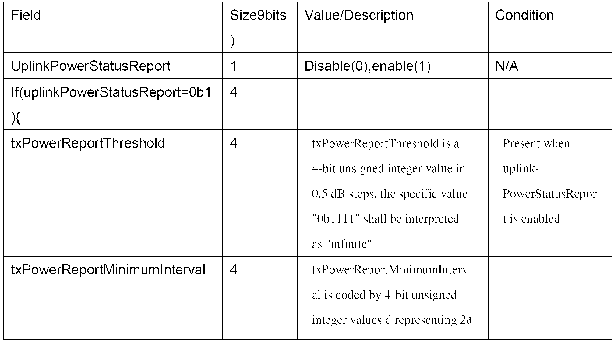

표 2를 참조하면, 상향링크 전력상태보고(UplinkPowerStatusReport)가 인에이블될 때, 단말은 표 2에 나타낸 AAI-UL-PSR-CFG 메시지에서  파라미터 값을 기지국으로 보고할 수 있다.
다음 표 3은 단말의 상향링크 전력 제어 상태 정보를 실어나르기 위해 사용되는 상향링크 전력상태보고 헤더를 나타낸다.
표 3 

표 3은 단말이 상향링크 전력상태보고를 하기 위한 상향링크 전력상태보고 헤더 포맷을 나타낸다. 상향링크 전력상태보고 헤더 포맷에는 플로우 식별자, MAC 시그널링 헤더 타입, 시그널링 헤더의 길이, 상향링크 전력 제어(ULPC) 파라미터를 업데이트했는지 여부를 나타내는 지시자, configuration change count, txPowerPsdBase, txSirDownlink, 이 시그널링 헤더와 관련된 물리 캐리어 인덱스(멀티 캐리어 시스템에서 이 시그널링 헤더와 관련된 캐리어 인덱스를 나타냄) 등이 포함될 수 있다.
상향링크 제어채널 및 데이터채널의 현재 전송에 대하여 설명한다. 제어 채널들 중에서의 동시 전송의 경우, 상향링크 전송 전력은 단말의 최대 전력 제한치에 도달하는 총 전송 전력까지 다음 표 4의 우선순위에 따른 제어채널의 순서로 할당이 이루어진다. 단말이 할당된 채널을 전송하기에 충분한 전력을 가지고 있지 못한 경우에는, 상기 수학식 1에 의해 결정된 전력 레벨을 충족시키지 못하더라도 단말은 남아있는 전력으로 이 채널들을 우선순위에 따라 전송할 수 있다. 다음 표 4는 채널들 간의 전력 할당 우선순위를 나타낸 표이다.
표 4 
표 4를 참조하면, 전송채널의 타입은 데이터 전송을 위한 데이터 채널과 제어 정보 전송을 위한 제어 채널로 일반적으로 구분할 수 있다. 상향링크 데이터는 링크 적응(link adaptation) 또는 HARQ(Hybrid Automatic Repeat reQuest) 등을 이용한 재전송의 기회가 있으나, 상향링크 제어신호에 대해서는 HARQ를 수행하지 하지 않아 재전송의 기회가 없는 것이 일반적이다. 따라서, 제어채널의 우선순위를 데이터채널에 비해 높게 둘 필요가 있다.
다만, 대역폭 요청은 다양한 방법을 통해 수행될 수 있으므로 재전송의 기회가 많다. 기지국으로부터 대역폭 요청의 ACK(ACKnowledgement) 신호를 수신하지 못한 단말은 예를 들어, 랜덤 엑세스(Random Access)에 기초한 대역폭 요청을 수행하거나, 대역폭 요청 시그널링 헤더를 이용하거나, 피기백된(piggybacked) 대역폭 요청을 수행하거나, 고속 피드백 채널을 이용한 대역폭 요청을 수행할 수 있다. 랜덤 엑세스 대역폭 요청은 피드백 신호의 전송 및 데이터 신호의 전송이 없을 때 대역폭 요청 채널을 통해 이루어지며, 대역폭 요청 시그널링 헤더는 기지국으로부터 대역폭요청 헤더에 대한 승인을 수신하면 그에 대한 응답으로서 상기 기지국에 전송될 수 있다. 피기백된 대역폭 요청은 대역폭 요청을 보내는 시점에 데이터가 있을 경우 데이터와 함께 상기 대역폭 요청을 전송하는 방법이다. 대역폭요청을 전송하는 시점에, 전송해야 할 고속 피드백 신호가 있으면, 상기 대역폭 요청은 주 고속 피드백채널(PFBCH)을 통해 단말이 기지국으로 전송할 수도 있다. 따라서, 표 4에서 대역폭 요청 채널은 원칙적으로는 제어채널의 일종이기는 하지만, 다양한 재전송 방법 및 기회가 많으므로 가장 낮은 우선순위를 갖는다.
표 4을 참조하면, 기지국의 데이터 전송에 대한 응답인 ACK(Acknowledgement)/NACK(Non-acknowledgement) 신호를 전송하기 위한 채널인 HARQ 피드백 채널은, 단말로부터 기지국으로의 재전송 요구를 줄여 패킷 데이터의 전송효율을 높이는 HARQ 동작을 수행하기 위해 필수적인 채널이므로 최고의 우선순위를 갖는다.
PFBCH/SFBCH 채널은 CQI(Channel Quality Indicator) 및 STC(Space Timing Coding) 속도 지시자, PMI(Precoding Matrix Index) 등의 전송에 사용되는 채널로서, 하향링크 스케줄링 및 하향링크 사용자 선택, 자원 할당에 관여하게 되므로 HARQ 피드백 채널 다음의 우선순위에 해당할 수 있다.
한편, 상향링크의 동기가 맞지 않게 되는 경우에는 기지국이 단말을 인식하지 못하여, 자원할당 및 그 이후의 통신을 적절히 수행할 수 없게 될 수 있다. 따라서, 특정 기지국에 일단 동기된 단말은 주기적 레인징 신호를 전송하여 동기를 유지하는 트랙킹을 수행할 필요가 있으므로, 단말과 기지국의 동기를 지속적으로 유지하기 위해 필요한 레인징 채널도 상위의 우선순위를 갖는다.
사운딩 참조신호(혹은 사운딩 신호)는 동기된 상태에서 전송되는 신호로서, 기지국은 단말로부터 수신한 사운딩 참조신호에 기초하여 상향링크 채널 상태를 추정하고, 추정된 채널 상태에 따라 스케줄링(예를 들어, 사용자선택 및 자원 할당 등)을 수행하게 된다. 단말이 사운딩 참조신호를 안정적으로 기지국에 전송하기 위해서는 단말이 기지국과의 동기를 유지하여야 할 것이므로 사운딩 참조신호가 전송되는 사운딩 채널이 동기된 레인징 채널보다 낮은 우선순위일 수 있다.
데이터의 경우에는 전송에 실패하더라도 재전송의 기회가 있으므로, HARQ 피드백채널, PFBCH/SFBCH 채널, 동기된 레인징 채널, 사운딩 채널에 비해 낮은 우선순위를 가질 수 있다.
한편, 상기 수학식 3과 같이 계산된 PSD(base)와 SIRDL을 단말이 기지국에 전송하면, 기지국은 데이터채널과 제어채널들에 대해 기대되는 전송 전력 레벨(expected transmit power level)을 예측할 수 있다. 다만, 이 경우에는 옵셋(offset)값은 절대값(absolute value)으로만 동작해야 함을 의미한다. 그러나, 옵셋이 축적된 값(accumulated value)으로 동작하게 되면 기지국은 현재 이 옵셋 요소 때문에 현재 단말의 전송파워를 예측하기 어렵다. 이는 전송 전력 제어 명령에 대한에 대한 수신 에러 혹은 여러 가지 이유로 기지국이 단말에 보낸 TPC 명령 값들과 단말이 실제로 적용한 값에 차이가 발생 할 수 있다.
또한, 제어채널(들)과 데이터채널이 동일 시간 및/또는 자원 구간 안에서 전송될 수 있기 때문에 이러한 단말의 리포팅 정보는 필요하다. 동시 할당/전송 시 데이터채널의 전송 전력은 제어채널의 전력 할당 후 남은 전력으로 결정되기에 축적된 TPC 명령값까지 고려한 제어채널에 대한 전력 정보가 중요해 진다. 따라서, 상기와 같은 전력상태보고(power status report)는 기지국이 단말의 현재 파워 상태를 충분히 파악하는데에는 어려움이 있다.
이에 추가하여, 하향링크/상향링크 멀티-캐리어를 사용하는 시스템에서, 단말의 총 전력 관점에서의 전력상태보고(power status report)가 수행될 필요가 있다. 또한, 이러한 전력상태보고는 기지국이 다음 전송을 위해 자원할당을 하는 경우에 도움이 되는 방향이어야 한다. 그러나, 상술한 바와 같이 아직까지는 이를 지원하기 위한 방법이 없다. 또한, 총 전력 관점에서의 단말의 동시 전송에 대한 구체적인 방법의 제시가 없었다.
이를 위해, 본 발명에서는 단말이 PSD(base)를 데이터채널과 제어채널을 구분하여 SIRDL 를 전송하고,다음 수학식 6 및 7과 같이 데이터채널 및 제어채널 별로 옵셋값을 적용하여 산출된 PSD를 기지국으로 전송하는 것을 제안한다.
수학식 6 
수학식 7 
상기 수학식 6 및 7에서 단위는 dBm,dB, 선형 값(linear value) 중 임의의 어느 하나를 사용해도 무방하다. 수학식 6 및 7에서 볼 수 있듯이 상기 수학식 1의 옵셋값이 축적된 값(accumulated value)으로 동작하게 될 경우에는 PSD(base)는 제어채널 부분과 데이터채널 부분으로 분리되어 전송될 필요가 있다. 이벤트가 발생한 시점에 제어채널 혹은 데이터채널이 할당되지 않을 수도 있다. 이때는 단말이 가지고 있는 가장 최근에 업데이트 된 축적된 TPC 명령값을 사용하면 된다. 이와 같은 맥락에서, 전력상태보고(PSR) 이벤트가 발생한 시점에 데이터채널 혹은 제어채널이 할당된 경우에는 단말의 프로세서(155)는 PSR 발생 시점의 옵셋값을 적용하여 PSD를 계산하는 것이 바람직할 수 있다. 둘 중 하나라도 축적된 모드로(즉, TPC 명령값을 누적하여 연산하는 모드) 동작하게 될 경우도 포함된다. 그렇지 않은 경우에는 즉 둘 다 절대값 모드로 동작하는 경우에는 수학식 1에서의 옵셋값과 같이 축적된 값이 아닌 절대값을 이용하여 계산하면 된다.
전력상태보고(PSR)가 데이터채널과 제어채널에 각각 별도의 옵셋값을 적용한 PSD(base)값과 그리고 SIRDL 의 조합으로 이루어질 때, 단말은 SIRDL 값을 상기 수학식 6 또는 상기 수학식 7의 PSD와 함께 리포팅하는 것이 바람직하다. 또는, 단말은 SIRDL 값을 상기 수학식 6 및 상기 수학식 7의 PSD와 동시에 리포딩하는 것도 가능하다. 즉, 단말은 상기 수학식 6 및 7 그리고 SIRDL 값을 조합하여 정보를 구성하고 이를 기지국으로 전송하는 것도 고려할 수 있다. 예를 들어, 상기 수학식 6과 SIRDL 값을 조합하여 구성하거나, 상기 수학식 7과 SIRDL 값을 조합하여 구성할 수 있다.
또 다른 실시예로서, 단말은 PSR 보고 시 PSD(base)을 다음 수학식 8 및 9와 같이 구성하여 전송하는 것도 가능하다.
수학식 8 
수학식 9 
상기 수학식 8 및 9에서 SINRtarget 값은 데이터채널과 제어채널 각각에서 계산된/혹은 시그널링 된 것으로 사용된다. 이 경우 다중 데이터/제어채널이 전송될 경우에는 PSD를 임의의 채널을 기준으로 정의할 수도 있다. 특히, 제어채널의 경우 SINRtarget 값이 채널 별로 서로 다르기 때문에, 일 예로서 HARQ 피드백채널을 기준으로 PSD를 정의하여 사용하는 것도 가능하다. 물론 HARQ 피드백 채널 이외의 다른 채널을 기준으로 PSD 레벨을 계산하는 것도 가능하다. 데이터채널에 대한 부분은 상기 수학식 1에서 계산된 값을 사용하면 된다. SINRtarget 에서 β를 항상 0으로 설정하여 기지국 관점에서 단말의 실제 PSD 레벨을 파악하는데 도움이 될 수 있다. 물론 β값이 그때 그때 적용된 값을 사용하는 것을 배제하지 않는다.
도 2는 본 발명에 따른 단말의 전력상태보고(PSR)를 전송하기 위한 과정의 일 예를 나타낸 도면이다.
도 2를 참조하면, 상술한 바와 같이 단말은 기지국으로부터 PSD(base) 값을 계산하기 위한 데이터채널 옵셋값(offsetdata)을 AAI-UL-POWER-ADJ 메시지를 통해 수신하고, 제어채널 별 옵셋값(offsetcontrol)은 PC-A-MAP IE 메시지를 통해 할 수 있다(S210). 단말은 기지국으로부터 offsetcontrol, offsetdata을 누적하여 수신하는데 PSR 이벤트가 발생하기 까지 이 값들을 누적하여 계산한다. 그리고, 단말의 프로세서(155)는 PSR 이벤트가 발생한 경우 기지국으로부터 하향링크 신호를 이용하여 하향링크 신호 대 간섭 전력 비율을 나타내는 SIRDL을 측정할 수 있다(S220). 그 후, 단말은 기지국으로부터 수신하여 누적된 offsetcontrol, offsetdata을 이용하여 각각 제어채널 및 데이터채널 별로 PSD(base)를 계산할 수 있다(S230). 그 후, 단말은 측정한 SIRDL 값, 계산된 PSD(base)(데이터 채널 및/또는 제어채널에 대응하는 PSD(base))을 기지국으로 전송해 줄 수 있다(S240). 앞서, PSD(base)와 SIRDL 을 다양한 형태로 조합하여 정보를 구성한 후 기지국으로 전송할 수 있음을 설명한 바 있다. 도 2에서 S210 내지 S230 단계를 순차적으로 표시하였지만 그 순서는 바뀔수도 있다.
한편, 무선통신 시스템이 부분 주파수 재사용(Fractional Frequency Reuse, FFR)을 채용하고 있는 경우에는 단말이 SIRDL 값을 FFR 파티션 별로 기지국에 리포팅하는 것을 제안한다. 이는 주파수 파티션(Frequency Partition, FP) 별로 SIRDL 의 통계적 특성 값이 다를 수 있기 때문이다. 따라서, 이러한 FFR 파티션을 고려한 보고로 보다 정교한 간섭 레벨 제어가 가능해 질 수 있다. 따라서, FFR 방식을 채용하는 무선통신 시스템에서 단말이 기지국으로보고 하는 SIRDL 값은 SIRDL(i)로 표현할 수 있고, 여기서 i는 FP 인덱스를 나타낸다. 물론 SIRDL 값은 앞서 설명한 바와 같이 하향링크 FFR 패턴(DL FFR pattern)에 따라서 그 통계적 특성이 다를 수 있다. 이 경우 하향링크 FFR 패턴과 상향링크 FFR 패턴(UL FFR pattern)이 같은 경우에는 FP 별 SIRDL 리포팅이 필요하나 서로 다른 경우에는 평균 SIRDL 값을 적용하는 것을 고려할 수 있다.
또한, 다중 상향링크 컴포넌트 캐리어(Multiple UL component carrier)를 채용하는 무선통신 시스템으로 확장하여, 상기 수학식 6 및 7은 다음 수학식 11 및 12와 같이, 그리고 SIRDL 값도 컴포넌트 캐리어(혹은 멀티 캐리어, 서빙 셀 등 다양한 형태로 호칭될 수 있다)를 고려하여 SIRDL, C 로 나타낼 수 있다. 단말의 프로세서(155)는 컴포넌트 캐리어 별로 독립적으로 PSD(base)를 계산할 수 있다.
수학식 10 
수학식 11 
여기서 C는 컴포넌트 캐리어 인덱스를 나타내고, 파라미터 값들은 상기 수학식 6 및 7에서 정의한 내용과 동일하다. 즉, 각 파라미터는 컴포넌트 캐리어 별로 계산된 값이다. 다음으로 상기 수학식 5에 나타낸 M은 SINRTarget 값은 SIRDL값과 TNS가 활성화 되어 있는 경우에는 이 두 값에 의해 영향을 많이 받는다. M값의 임계치(threshold)가 0.5dB 간격으로 기지국에서 시그널링하도록 되어 있다. 그러나, L 값의 변화 보다 SIRDL 값과 TNS의 변화 값에 의해 보다 많은 상향링크 시그널링이 발생할 수 있다. 단말의 다음 전송에 필요한 전송전력을 예측하기 위해서는 가장 많은 영향을 미치는 L, SIRDL 이 중요한 요소이다.
따라서, 본 발명에서는 M값을 L, SIRDL 값을 이용한 함수 f(L,SIRDL)로 구성하는 것을 제안한다. 다음과 같이 구성하는 방법을 고려해 볼 수 있다. M=L+SIRDL로 정의하거나, 또는 β=0 일때 M=L+SINRtarget 로 정의하거나, 또는 M=L로 정의하거나, 또는 M= SIRDL로 정의하는 것도 가능하다. 또는, 이들 식의 다양한 조합으로 M을 구성할 수도 있다. 이 경우 M에 대한 임계치가 2개 중 하나로 이벤트 발생하여 리포팅 될 수 있다.
IEEE 802.16m 시스템 다중 상향링크 컴포넌트 캐리어로 확장하여 동작할 경우 수학식 10, 11처럼 확장하여 상기 수학식 1 및 2는 각각 다음 수학식 12 및 13과 같이 변경된다. 이는 각 상향링크 컴포넌트 캐리어 별로 독립적인 전력 제어 동작을 하는 것을 기본으로 한다.
수학식 12 
수학식 13 
여기서, C는 컴포넌트 캐리어 인덱스이고, 나머지 파라미터는 상기 수학식 1 및 수학식 2에서 사용된 파라미터와 동일하며 다만 컴포넌트 캐리어 인덱스 만이 추가된 것이다.
PSD(base) = L + NI 인 식에서 NI 값은 기지국이 단말로 방송하는 값이다. NI 메시지는 AAI-SCD 메시지처럼 시간 인덱스가 없기 때문에 단말이 어느 시점의 NI 값을 사용하고 있는지 단말과 기지국은 알 수 없다. 상기 NI 값은 L과 dB연산 함으로써 PSD(base) 정보량을 줄이는데 도움을 준다. 그러나, 이 값이 어느 시점의 값이 사용되었는지 기지국이 예측하지 못한다면 PSD(base)값의 예측하는 정확도가 떨어진다. 이는 다시 단말의 부정확한 스케줄링 문제를 야기하게 된다.
NI 메시지를 단말이 수신하지 못할 수도 있기 때문에 시간 인덱스(예를 들어, 프레임 인덱스, 또는 AAI-SCD 메시지의 변경 카운터(change counter)와 같이 NI 값을보낸 시점에 관한 정보) 정보를 PSR에 함께 보내는 것도 가능하다. 혹은 NI 의 값이 단순 정보량을 줄이기 위한 용도로 사용된 값으로 큰 의미가 없으므로 미리정한 기본 설정 값을(dB 또는 선형 스케일(linear scale)) 사용하는 것도 가능하다. 이는 단말과 기지국이 미리 알고 있는 값으로 시스템 정보를 단말에 알려 줄 때(네트워크 진입/재진입 시) 알려주어 사용하면 된다. 또는, 그 값을 고정하여 단말과 기지국이 사용하는 것도 가능하다. 이는 추가 시그널링이 필요없다는 장점이 있다. 또한, 하나의 값 혹은 여러 값의 세트로 구성하여 사용하는 것도 가능하다.
멀티 캐리어를 사용하는 시스템에서, 단말은 전력상태보고(PSR)를 구성된/활성화된/스케줄링된 상향링크 캐리어에서 개별 캐리어에 대한 PSR 정보를 동시에 기지국에 전송할 수 있다. 기지국은 보고된 PSR 정보에 기초하여 단말의 다음 전송에 대한 자원할당을 하는데 사용한다.
예를 들어, 활성화된 컴포넌트 캐리어가 3개이고 자원할당 받은 컴포넌트 캐리어는는 2개 일 경우, PSR 트리거링이 발생하면, 단말은 3개 컴포넌트 캐리어 개별에 대한 정보를 동시에 기지국에 전송하여야 한다. 이를 위해서 PSR을 위한 상태 전송 조건(status transmission condition)이 단말당 하나로 정해져야 한다. 이에 대한, M 값을 위한 기준 하향링크/상향링크 캐리어는 기지국이 단말에게 알려주거나 미리 정한 값으로 사용한다.
상기 표 2에서 캐리어 특정 물리 제어 모드(Carrier-Specific PHY control mode)에 해당하는 부분이 AAI-UL-PSR-CFG 메시지에서 생략되어도 상관없다. 이 부분을 생략하여 사용하더라도 상향링크 캐리어에 대한 PSR-CFG는 하나로 구성되어 동일 적용하거나 기준 하향링크/상향링크 캐리어 하나에 대해서만 트리거링 조건을 설정하여 사용하면 문제가 되지 않는다.
본 발명에서는 PSR 리포팅을 상기 표 2를 이용하되, 일부 내용을 변경한 형태인 다음 표 5를 제안한다.
표 5 

상기 표 5에서는 하나의 상향링크 PSR 헤더 포맷으로 여러 캐리어에 대한 정보를 모두 포함하고 있어 동시 전송 시 개별 컴포넌트 캐리어로 구성하는 경우 보다 정보량이 적어지고 하나의 상향링크 컴포넌트 캐리어에서 전송하는 것도 효율적이다. 추가하여 상기 PSR를 전송되는 시점에서 단말이 각 상향링크 캐리어 별로 최대 전력 레벨도 함께 포함하여 전송하는 것도 가능하다. 이는 기지국이 단말의 총 전력을 파악하는데 많은 도움을 준다.
하향링크/상향링크 멀티-캐리어를 사용하는 시스템에서 단말은 다중 전송(multiple transmission)을 수행 할 수 있다. 그러나, 할당된 자원에 대한 전송 전력의 합이 한정된 단말의 총 전력을 초과하는 경우가 발생할 수 있다. 이 경우, 단말은 미리 정해진 전송 채널의 우선 순위에 따라 전력을 할당하게 된다. 더 확장하여 멀티-캐리어에서 다중 전송이 일어나는 경우에는 다음과 같은 방법을 고려 할 수 있다.
먼저, 각 단일 캐리어에서 해당 캐리어의 우선 순위대로 전력을 할당하고 난 다음 총 전력 제한을 적용하여 각 단일 캐리어에서 배열(ordering)한 것을 바탕으로 다시 전체 순서를 구성할 수 있다. 이 합이 단말의 전송 가능한 총 전력을 넘지 않도록 한다. 단말의 총 전력을 초과하는 경우, 동일 채널이 각각 캐리어에 존재 할 경우 프라이머리 캐리어(primary carrier)가 우선순위를 가지고 프라이머리 캐리어를 제외한 캐리어들에서는 동일 가중치(weight)를 적용하여 전력 스케일링(power scaling)을 수행할 수 있다.
또는, 단말의 전체 할당 받은 채널(즉, 전송해야 할 채널)에 대해 우선 순위를 사전에 정의해 두고, 동일 채널이 여러 상향링크 컴포넌트에 존재할 경우에는 1)프라이머리 캐리이에 우선순위를 두고, 프라이머리 캐리어를 제외한 캐리어에서는 동일 가중치로 전력 스케일링하거나 2)모든 캐리어에 동일 가중치를 적용하거나, 3) 캐리어 별로 미리 정한 가중치를 적용하여 전력 스케일링을 수행할 수 있다.
이와 같은 본 발명의 PSR 리포팅 방식에 관한 다양한 실시예들에 의해, 기지국이 단말의 전력을 정확하게 예측 할 수 있고 자원 할당 및 단말의 전송 전력 제어가 보다 정교해 진다. 또한, 멀티 캐리어와 FFR 방식을 채용하는 시스템에서도 기지국이 단말의 전력을 정확하게 예측할 수 있는 효과가 있다.
이상에서 설명된 실시예들은 본 발명의 구성요소들과 특징들이 소정 형태로 결합된 것들이다. 각 구성요소 또는 특징은 별도의 명시적 언급이 없는 한 선택적인 것으로 고려되어야 한다. 각 구성요소 또는 특징은 다른 구성요소나 특징과 결합되지 않은 형태로 실시될 수 있다. 또한, 일부 구성요소들 및/또는 특징들을 결합하여 본 발명의 실시예를 구성하는 것도 가능하다. 본 발명의 실시예들에서 설명되는 동작들의 순서는 변경될 수 있다. 어느 실시예의 일부 구성이나 특징은 다른 실시예에 포함될 수 있고, 또는 다른 실시예의 대응하는 구성 또는 특징과 교체될 수 있다. 특허청구범위에서 명시적인 인용 관계가 있지 않은 청구항들을 결합하여 실시예를 구성하거나 출원 후의 보정에 의해 새로운 청구항으로 포함시킬 수 있음은 자명하다.
본 발명은 본 발명의 정신 및 필수적 특징을 벗어나지 않는 범위에서 다른 특정한 형태로 구체화될 수 있음은 당업자에게 자명하다. 따라서, 상기의 상세한 설명은 모든 면에서 제한적으로 해석되어서는 아니되고 예시적인 것으로 고려되어야 한다. 본 발명의 범위는 첨부된 청구항의 합리적 해석에 의해 결정되어야 하고, 본 발명의 등가적 범위 내에서의 모든 변경은 본 발명의 범위에 포함된다.
전력상태보고를 전송하기 위한 방법 및 이를 위한 단말 장치는 3GPP LTE, LTE-A, IEEE 802.16 등 다양한 통신 시스템에서 산업상으로 이용가능하다.
Claims (14)
- 무선통신 시스템에서 단말이 전력상태보고를 전송하는 방법에 있어서,기지국으로부터 상향링크 전력 제어를 위한 데이터채널 옵셋값 및 제어채널 옵셋값 중 적어도 하나를 수신하는 단계;상기 수신한 데이터채널 및 제어채널 별 옵셋값 중 적어도 하나에 기초하여 상기 데이터 채널 및 제어채널 중 적어도 하나에 대한 기본 상향링크 전송 전력 레벨을 결정하는 단계; 및상기 결정된 적어도 하나의 기본 상향링크 전송 전력 레벨을 상기 기지국으로 전송하는 단계를 포함하는, 단말의 전력상태보고 전송 방법.
- 제 1항에 있어서,상기 기지국으로부터 수신한 하향링크 신호를 이용하여 하향링크 신호 대 간섭 전력 비율값을 계산하는 단계를 더 포함하는, 단말의 전력상태보고 전송 방법.
- 제 2항에 있어서,상기 단말이 측정한 하향링크 신호 대 간섭 전력의 비율값은 상기 적어도 하나의 기본 상향링크 전송 전력 레벨과 함께 전송되는, 단말의 전력상태보고 전송 방법.
- 제 1항에 있어서,상기 결정된 기본 상향링크 전송 전력 레벨은 캐리어 별로 대응하는 값인, 단말의 전력상태보고 전송 방법.
- 제 2항에 있어서,상기 측정된 하향링크 신호 대 간섭 전력의 비율 값은 부분 주파수 재사용(Fractional Frequency Reuse, FFR) 파티션 인덱스 별로 측정된 것인, 단말의 전력상태보고 전송 방법.
- 제 1항에 있어서,상기 기본 상향링크 전송 전력 레벨을 결정하는데 사용되는 옵셋값은 각각 상기 기지국으로부터 수신한 데이터채널 옵셋값 및 제어채널 별 옵셋값을 누적하여 산출한 값인, 단말의 전력상태보고 전송 방법.
- 제 6항에 있어서,상기 데이터채널을 위한 기본 상향링크 전력 레벨과 상기 제어채널을 위한 기본 상향링크 전력 레벨은 각각 다음 수학식 A 및 수학식 B에 의해 결정되는 단말의 전력상태보고 전송 방법:[수학식 A]
 [수학식 B]
 여기서, L은 상기 단말에 의해 추정된 현재의 평균 하향링크 전파 손실(propagation loss), NI는 기지국에서 추정한 부반송파 별(per subcarrier) 평균 잡음 및 간섭 레벨이고, OffsetData 및 Offsetcontrol은 각각 데이터 채널 및 제어채널의 전력 옵셋을 보정하기 위한 값이다.
 - 무선통신 시스템에서 전력상태보고를 전송하기 위한 단말 장치에 있어서,기지국으로부터 상향링크 전력 제어를 위한 데이터채널 옵셋값 및 제어채널 옵셋값 중 적어도 하나를 수신하는 수신기;상기 수신한 데이터채널 및 제어채널 별 옵셋값 중 적어도 하나에 기초하여 상기 데이터 채널 및 제어채널 중 적어도 하나에 대해 기본 상향링크 전송 전력 레벨을 결정하는 프로세서; 및상기 결정된 적어도 하나의 기본 상향링크 전송 전력 레벨을 상기 기지국으로 전송하는 송신기를 포함하는, 단말 장치.
- 제 8항에 있어서,상기 프로세서는 상기 기지국으로부터 수신한 하향링크 신호를 이용하여 하향링크 신호 대 간섭 전력 비율값을 계산하며,상기 송신기는 상기 프로세서가 측정한 하향링크 신호 대 간섭 전력의 비율값을 상기 적어도 하나의 기본 상향링크 전송 전력 레벨과 함께 전송하는, 단말 장치.
- 제 8항에 있어서,상기 결정된 기본 상향링크 전송 전력 레벨은 캐리어 별로 대응하는 값인, 단말 장치.
- 제 9항에 있어서,상기 측정된 하향링크 신호 대 간섭 전력의 비율 값은 부분 주파수 재사용(Fractional Frequency Reuse, FFR) 파티션 인덱스 별로 측정된 것인, 단말 장치.
- 제 8항에 있어서,상기 프로세서가 상기 기본 상향링크 전송 전력 레벨을 결정하기 위해 사용하는 옵셋값은 상기 기지국으로부터 각각 수신한 데이터채널 옵셋값 및 제어채널 별 옵셋값을 누적하여 산출한 값인, 단말 장치.
- 제 12항에 있어서,상기 프로세서는 상기 데이터채널을 위한 기본 상향링크 전력 레벨과 상기 제어채널을 위한 기본 상향링크 전력 레벨을 각각 다음 수학식 C 및 수학식 D에 의해 결정하는 단말 장치:[수학식 C]
 [수학식 D]
 여기서, L은 상기 단말에 의해 추정된 현재의 평균 하향링크 전파 손실(propagation loss), NI는 기지국에서 추정한 부반송파 별(per subcarrier) 평균 잡음 및 간섭 레벨이고, OffsetData 및 Offsetcontrol은 각각 데이터 채널 및 제어채널의 전력 옵셋을 위한 보정하기 위한 값이다.
 - 제 12항에 있어서,상기 데이터채널 옵셋값 및 제어채널 별로 누적하여 산출된 옵셋값은 전력상태보고 트리거링 시점에서 누적된 옵셋값인, 단말 장치.
Priority Applications (1)
| Application Number | Priority Date | Filing Date | Title |
|---|---|---|---|
| US13/884,346 US9100922B2 (en) | 2010-11-09 | 2011-11-09 | Method and terminal apparatus for transmitting a power status report in a wireless communication system |
Applications Claiming Priority (2)
| Application Number | Priority Date | Filing Date | Title |
|---|---|---|---|
| US41148310P | 2010-11-09 | 2010-11-09 | |
| US61/411,483 | 2010-11-09 |
Publications (3)
| Publication Number | Publication Date |
|---|---|
| WO2012064100A2 true WO2012064100A2 (ko) | 2012-05-18 |
| WO2012064100A3 WO2012064100A3 (ko) | 2012-09-20 |
| WO2012064100A9 WO2012064100A9 (ko) | 2012-11-08 |
Family
ID=46051420
Family Applications (1)
| Application Number | Title | Priority Date | Filing Date |
|---|---|---|---|
| PCT/KR2011/008505 WO2012064100A2 (ko) | 2010-11-09 | 2011-11-09 | 무선통신 시스템에서 전력상태보고를 전송하기 위한 방법 및 이를 위한 단말 장치 |
Country Status (2)
| Country | Link |
|---|---|
| US (1) | US9100922B2 (ko) |
| WO (1) | WO2012064100A2 (ko) |
Families Citing this family (72)
| Publication number | Priority date | Publication date | Assignee | Title |
|---|---|---|---|---|
| US9071286B2 (en) | 2011-05-26 | 2015-06-30 | Cohere Technologies, Inc. | Modulation and equalization in an orthonormal time-frequency shifting communications system |
| US11943089B2 (en) | 2010-05-28 | 2024-03-26 | Cohere Technologies, Inc. | Modulation and equalization in an orthonormal time-shifting communications system |
| US9130638B2 (en) | 2011-05-26 | 2015-09-08 | Cohere Technologies, Inc. | Modulation and equalization in an orthonormal time-frequency shifting communications system |
| US10681568B1 (en) | 2010-05-28 | 2020-06-09 | Cohere Technologies, Inc. | Methods of data channel characterization and uses thereof |
| US9071285B2 (en) | 2011-05-26 | 2015-06-30 | Cohere Technologies, Inc. | Modulation and equalization in an orthonormal time-frequency shifting communications system |
| US10667148B1 (en) | 2010-05-28 | 2020-05-26 | Cohere Technologies, Inc. | Methods of operating and implementing wireless communications systems |
| US9444514B2 (en) | 2010-05-28 | 2016-09-13 | Cohere Technologies, Inc. | OTFS methods of data channel characterization and uses thereof |
| US8976851B2 (en) | 2011-05-26 | 2015-03-10 | Cohere Technologies, Inc. | Modulation and equalization in an orthonormal time-frequency shifting communications system |
| KR20120006259A (ko) * | 2010-07-12 | 2012-01-18 | 삼성전자주식회사 | 이동 통신 시스템에서 업링크 송신 전력 상태 보고 장치 및 방법 |
| US8711703B2 (en) * | 2010-10-29 | 2014-04-29 | Telefonaktiebolaget L M Ericsson (Publ) | Load balancing in shortest-path-bridging networks |
| US9031141B2 (en) | 2011-05-26 | 2015-05-12 | Cohere Technologies, Inc. | Modulation and equalization in an orthonormal time-frequency shifting communications system |
| US9450773B2 (en) * | 2011-12-22 | 2016-09-20 | Verizon Patent And Licensing Inc. | Multicast resource optimization |
| US10090972B2 (en) | 2012-06-25 | 2018-10-02 | Cohere Technologies, Inc. | System and method for two-dimensional equalization in an orthogonal time frequency space communication system |
| US9929783B2 (en) | 2012-06-25 | 2018-03-27 | Cohere Technologies, Inc. | Orthogonal time frequency space modulation system |
| US10003487B2 (en) | 2013-03-15 | 2018-06-19 | Cohere Technologies, Inc. | Symplectic orthogonal time frequency space modulation system |
| US9967758B2 (en) | 2012-06-25 | 2018-05-08 | Cohere Technologies, Inc. | Multiple access in an orthogonal time frequency space communication system |
| US10411843B2 (en) | 2012-06-25 | 2019-09-10 | Cohere Technologies, Inc. | Orthogonal time frequency space communication system compatible with OFDM |
| US9912507B2 (en) | 2012-06-25 | 2018-03-06 | Cohere Technologies, Inc. | Orthogonal time frequency space communication system compatible with OFDM |
| US10469215B2 (en) | 2012-06-25 | 2019-11-05 | Cohere Technologies, Inc. | Orthogonal time frequency space modulation system for the Internet of Things |
| US10097329B2 (en) * | 2013-11-08 | 2018-10-09 | Spidercloud Wireless, Inc. | Fractional frequency reuse schemes assigned to radio nodes in an LTE network |
| US9554281B2 (en) | 2013-11-08 | 2017-01-24 | Spidercloud Wireless, Inc. | Fractional frequency reuse schemes assigned to clusters of radio nodes in an LTE radio access network |
| US10090973B2 (en) | 2015-05-11 | 2018-10-02 | Cohere Technologies, Inc. | Multiple access in an orthogonal time frequency space communication system |
| US10158394B2 (en) | 2015-05-11 | 2018-12-18 | Cohere Technologies, Inc. | Systems and methods for symplectic orthogonal time frequency shifting modulation and transmission of data |
| US10574317B2 (en) | 2015-06-18 | 2020-02-25 | Cohere Technologies, Inc. | System and method for providing wireless communication services using configurable broadband infrastructure shared among multiple network operators |
| US9866363B2 (en) * | 2015-06-18 | 2018-01-09 | Cohere Technologies, Inc. | System and method for coordinated management of network access points |
| KR20180051485A (ko) | 2015-06-27 | 2018-05-16 | 코히어 테크널러지스, 아이엔씨. | Ofdm과 호환가능한 직교 시간 주파수 공간 통신 시스템 |
| US10892547B2 (en) | 2015-07-07 | 2021-01-12 | Cohere Technologies, Inc. | Inconspicuous multi-directional antenna system configured for multiple polarization modes |
| KR102616669B1 (ko) | 2015-07-12 | 2023-12-21 | 코히어 테크놀로지스, 아이엔씨. | 복수의 협대역 부-반송파 상에서의 직교 시간 주파수 공간 변조 |
| CN108770382B (zh) | 2015-09-07 | 2022-01-14 | 凝聚技术公司 | 使用正交时间频率空间调制的多路存取的方法 |
| WO2017087706A1 (en) | 2015-11-18 | 2017-05-26 | Cohere Technologies | Orthogonal time frequency space modulation techniques |
| KR102655272B1 (ko) | 2015-12-09 | 2024-04-08 | 코히어 테크놀로지스, 아이엔씨. | 복소 직교 함수를 이용하는 파일럿 패킹 |
| WO2017147439A1 (en) | 2016-02-25 | 2017-08-31 | Cohere Technologies | Reference signal packing for wireless communications |
| WO2017165697A1 (en) | 2016-03-23 | 2017-09-28 | Cohere Technologies | Receiver-side processing of orthogonal time frequency space modulated signals |
| US9667307B1 (en) | 2016-03-31 | 2017-05-30 | Cohere Technologies | Wireless telecommunications system for high-mobility applications |
| EP3437190B1 (en) | 2016-03-31 | 2023-09-06 | Cohere Technologies, Inc. | Channel acquisition using orthogonal time frequency space modulated pilot signal |
| EP3437279B1 (en) | 2016-04-01 | 2021-03-03 | Cohere Technologies, Inc. | Iterative two dimensional equalization of orthogonal time frequency space modulated signals |
| KR102250054B1 (ko) | 2016-04-01 | 2021-05-07 | 코히어 테크널러지스, 아이엔씨. | Otfs 통신 시스템에서의 tomlinson-harashima 프리코딩 |
| CN109076056B (zh) | 2016-04-21 | 2022-07-12 | 瑞典爱立信有限公司 | 在终端设备和网络设备中使用的方法及相关联的设备 |
| WO2017201467A1 (en) | 2016-05-20 | 2017-11-23 | Cohere Technologies | Iterative channel estimation and equalization with superimposed reference signals |
| US11153880B2 (en) * | 2016-08-09 | 2021-10-19 | Qualcomm Incorporated | Power allocation across multiple carriers using shared and dedicated radio frequency spectrum |
| EP3497785B1 (en) | 2016-08-12 | 2024-03-13 | Cohere Technologies, Inc. | Method for multi-user multiplexing of orthogonal time frequency space signals |
| WO2018032016A1 (en) | 2016-08-12 | 2018-02-15 | Cohere Technologies | Localized equalization for channels with intercarrier interference |
| EP3497799A4 (en) | 2016-08-12 | 2020-04-15 | Cohere Technologies, Inc. | MULTILEVEL ITERATIVE EQUALIZATION AND DECODING |
| WO2018064587A1 (en) | 2016-09-29 | 2018-04-05 | Cohere Technologies | Transport block segmentation for multi-level codes |
| EP3520310B1 (en) | 2016-09-30 | 2021-10-27 | Cohere Technologies, Inc. | Uplink user resource allocation for orthogonal time frequency space modulation |
| WO2018091082A1 (en) * | 2016-11-16 | 2018-05-24 | Huawei Technologies Duesseldorf Gmbh | Radio device and radio cell with multiplexed data sequences with unequal power allocation |
| WO2018106731A1 (en) | 2016-12-05 | 2018-06-14 | Cohere Technologies | Fixed wireless access using orthogonal time frequency space modulation |
| EP3566379A4 (en) | 2017-01-09 | 2020-09-09 | Cohere Technologies, Inc. | PILOT ENCRYPTION FOR CHANNEL ESTIMATION |
| WO2018140837A1 (en) | 2017-01-27 | 2018-08-02 | Cohere Technologies | Variable beamwidth multiband antenna |
| US10568143B2 (en) | 2017-03-28 | 2020-02-18 | Cohere Technologies, Inc. | Windowed sequence for random access method and apparatus |
| US11817987B2 (en) | 2017-04-11 | 2023-11-14 | Cohere Technologies, Inc. | Digital communication using dispersed orthogonal time frequency space modulated signals |
| WO2018195548A1 (en) | 2017-04-21 | 2018-10-25 | Cohere Technologies | Communication techniques using quasi-static properties of wireless channels |
| EP3616265A4 (en) | 2017-04-24 | 2021-01-13 | Cohere Technologies, Inc. | MULTI-HARNESS ANTENNA DESIGNS AND OPERATION |
| EP3616341A4 (en) | 2017-04-24 | 2020-12-30 | Cohere Technologies, Inc. | DIGITAL COMMUNICATION USING LATTICE DISTRIBUTION MULTIPLEXING |
| KR102612426B1 (ko) | 2017-07-12 | 2023-12-12 | 코히어 테크놀로지스, 아이엔씨. | Zak 변환에 기초한 데이터 변조 기법 |
| CA3063783A1 (en) * | 2017-08-04 | 2019-02-07 | Guangdong Oppo Mobile Telecommunications Corp., Ltd. | Wireless communication method and terminal device |
| US11546068B2 (en) | 2017-08-11 | 2023-01-03 | Cohere Technologies, Inc. | Ray tracing technique for wireless channel measurements |
| WO2019036492A1 (en) | 2017-08-14 | 2019-02-21 | Cohere Technologies | ASSIGNMENT OF TRANSMISSION RESOURCES BY DIVISION OF BLOCKS OF PHYSICAL RESOURCES |
| US11102034B2 (en) | 2017-09-06 | 2021-08-24 | Cohere Technologies, Inc. | Lattice reduction in orthogonal time frequency space modulation |
| WO2019051427A1 (en) | 2017-09-11 | 2019-03-14 | Cohere Technologies, Inc. | WIRELESS LOCAL NETWORKS USING ORTHOGONAL TIME-FREQUENCY SPACE MODULATION |
| WO2019055861A1 (en) | 2017-09-15 | 2019-03-21 | Cohere Technologies, Inc. | REALIZING SYNCHRONIZATION IN AN ORTHOGONAL SPACE-FREQUENCY SPACE SIGNAL RECEIVER |
| WO2019060596A2 (en) | 2017-09-20 | 2019-03-28 | Cohere Technologies, Inc. | LOW COST ELECTROMAGNETIC POWER SUPPLY NETWORK |
| WO2019068053A1 (en) | 2017-09-29 | 2019-04-04 | Cohere Technologies, Inc. | ERROR CORRECTION WITHOUT RETURN CIRCUIT USING LOW DENSITY NON-BINARY PARITY CHECK CODES |
| EP3704802B1 (en) | 2017-11-01 | 2024-01-03 | Cohere Technologies, Inc. | Precoding in wireless systems using orthogonal time frequency space multiplexing |
| US11184122B2 (en) | 2017-12-04 | 2021-11-23 | Cohere Technologies, Inc. | Implementation of orthogonal time frequency space modulation for wireless communications |
| EP3750252A4 (en) | 2018-02-08 | 2021-08-11 | Cohere Technologies, Inc. | CHANNEL ESTIMATE ASPECTS FOR ORTHOGONAL TIME-FREQUENCY SPATIAL MODULATION FOR WIRELESS COMMUNICATIONS |
| US11489559B2 (en) | 2018-03-08 | 2022-11-01 | Cohere Technologies, Inc. | Scheduling multi-user MIMO transmissions in fixed wireless access systems |
| EP3807952A4 (en) | 2018-06-13 | 2021-07-28 | Cohere Technologies, Inc. | RECIPROCAL CALIBRATION FOR CHANNEL ESTIMATE BASED ON SECOND ORDER STATISTICS |
| US11522600B1 (en) | 2018-08-01 | 2022-12-06 | Cohere Technologies, Inc. | Airborne RF-head system |
| CN112534888B (zh) * | 2018-08-09 | 2023-10-10 | 联想(新加坡)私人有限公司 | 上行链路传输功率分配 |
| KR102541220B1 (ko) * | 2018-11-21 | 2023-06-09 | 삼성전자 주식회사 | 무선 통신 시스템에서 신호를 송수신하는 방법 및 장치 |
| CN111093257A (zh) * | 2019-08-07 | 2020-05-01 | 中兴通讯股份有限公司 | 功率控制方法、通信节点和存储介质 |
Citations (3)
| Publication number | Priority date | Publication date | Assignee | Title |
|---|---|---|---|---|
| KR20020073561A (ko) * | 2000-11-29 | 2002-09-27 | 마츠시타 덴끼 산교 가부시키가이샤 | 무선 인프라 장치 |
| KR20080056621A (ko) * | 2006-12-18 | 2008-06-23 | 삼성전자주식회사 | 무선통신 시스템에서 상향링크를 통해 데이터 및 제어정보를 송수신하는 방법 및 장치 |
| KR20090113342A (ko) * | 2001-08-20 | 2009-10-29 | 콸콤 인코포레이티드 | 통신 시스템에서 다중 포맷을 갖는 채널에 대한 전력을 제어하는 방법 및 장치 |
Family Cites Families (33)
| Publication number | Priority date | Publication date | Assignee | Title |
|---|---|---|---|---|
| US6173162B1 (en) * | 1997-06-16 | 2001-01-09 | Telefonaktiebolaget Lm Ericsson (Publ) | Multiple code channel power control in a radio communication system |
| US6996069B2 (en) * | 2000-02-22 | 2006-02-07 | Qualcomm, Incorporated | Method and apparatus for controlling transmit power of multiple channels in a CDMA communication system |
| EP1177646B1 (en) * | 2000-03-10 | 2009-02-25 | Samsung Electronics Co., Ltd. | Method for performing handoff in a wireless communication system |
| FR2817094B1 (fr) * | 2000-11-17 | 2003-02-07 | Cit Alcatel | Procede pour le controle de puissance d'emission dans un systeme de radiocommunications mobiles |
| JP3956085B2 (ja) * | 2000-12-20 | 2007-08-08 | 日本電気株式会社 | 送信回路 |
| KR100433893B1 (ko) * | 2001-01-15 | 2004-06-04 | 삼성전자주식회사 | 협대역 시분할 듀플렉싱 부호분할다중접속 통신시스템의전력 제어 방법 및 장치 |
| JP3736429B2 (ja) * | 2001-02-21 | 2006-01-18 | 日本電気株式会社 | セルラシステム、基地局、移動局並びに通信制御方法 |
| KR100459573B1 (ko) * | 2001-08-25 | 2004-12-03 | 삼성전자주식회사 | 고속 순방향 패킷 접속 방식을 사용하는 통신 시스템에서역방향 전송 전력 오프셋과 고속 순방향 공통 채널 전력레벨을 송수신하는 장치 및 방법 |
| DE60239751D1 (de) * | 2001-10-19 | 2011-05-26 | Ntt Docomo Inc | Funksteuervorrichtung, basisstation, funksteuerverfahren, mobilpaketkommunikations system, mobilstation, funksteuerprogramm und computerlesbares aufzeichnungsmedium |
| KR100832117B1 (ko) * | 2002-02-17 | 2008-05-27 | 삼성전자주식회사 | 고속 순방향 패킷 접속 방식을 사용하는 이동통신 시스템에서 역방향 송신전력 오프셋 정보를 송수신하는 장치 및 방법 |
| JP2004080235A (ja) * | 2002-08-14 | 2004-03-11 | Nec Corp | セルラシステム、移動局、基地局及びそれに用いる送信電力制御方法並びにそのプログラム |
| JP3574442B2 (ja) * | 2002-08-20 | 2004-10-06 | 松下電器産業株式会社 | 送信電力制御方法および無線通信装置 |
| JP4250002B2 (ja) * | 2003-03-05 | 2009-04-08 | 富士通株式会社 | 適応型変調伝送システム及び適応型変調制御方法 |
| US20050152279A1 (en) * | 2004-01-13 | 2005-07-14 | Robertson Brett L. | Downlink power control in wireless communications networks and methods |
| GB2421402B (en) * | 2004-12-17 | 2007-04-11 | Motorola Inc | A transmitter, a cellular communication system and method of transmitting radio signals therefor |
| US20060146756A1 (en) * | 2004-12-30 | 2006-07-06 | Fan Wang | Downlink resource allocation for time offset downlink packets |
| US20060281417A1 (en) * | 2005-05-10 | 2006-12-14 | Ntt Docomo, Inc. | Transmission rate control method and mobile station |
| US8098667B2 (en) * | 2005-06-16 | 2012-01-17 | Qualcomm Incorporated | Methods and apparatus for efficient providing of scheduling information |
| US8654712B2 (en) * | 2005-06-16 | 2014-02-18 | Qualcomm Incorporated | OFDMA reverse link scheduling |
| US7965789B2 (en) * | 2005-08-22 | 2011-06-21 | Qualcomm Incorporated | Reverse link power control for an OFDMA system |
| JP4761890B2 (ja) * | 2005-08-23 | 2011-08-31 | 株式会社エヌ・ティ・ティ・ドコモ | 伝送速度制御方法、無線基地局及び無線回線制御局 |
| KR101229564B1 (ko) * | 2006-06-12 | 2013-02-04 | 삼성전자주식회사 | 통신 시스템에서의 인접 섹터 간섭을 고려한 전력 제어 및스케줄링 방법 |
| US8442572B2 (en) * | 2006-09-08 | 2013-05-14 | Qualcomm Incorporated | Method and apparatus for adjustments for delta-based power control in wireless communication systems |
| US8195097B2 (en) * | 2006-09-08 | 2012-06-05 | Qualcomm Incorporated | Serving sector interference broadcast and corresponding RL traffic power control |
| US8670777B2 (en) * | 2006-09-08 | 2014-03-11 | Qualcomm Incorporated | Method and apparatus for fast other sector interference (OSI) adjustment |
| US8599706B2 (en) * | 2006-10-03 | 2013-12-03 | Qualcomm Incorporated | Random access signaling transmission for system access in wireless communication |
| US8954105B2 (en) | 2006-12-18 | 2015-02-10 | Samsung Electronics Co., Ltd. | Method and apparatus for transmitting/receiving data and control information through an uplink in a wireless communication system |
| US8570959B2 (en) * | 2007-03-01 | 2013-10-29 | Ntt Docomo, Inc. | Base station apparatus and communication control method |
| US8886245B2 (en) * | 2007-03-09 | 2014-11-11 | Qualcomm Incorporated | Messaging scheme for controlling uplink transmit power of a wireless device |
| WO2008123148A1 (ja) * | 2007-03-30 | 2008-10-16 | Ntt Docomo, Inc. | 移動通信システム、基地局装置、ユーザ装置及び方法 |
| US20090109912A1 (en) * | 2007-10-25 | 2009-04-30 | Interdigital Patent Holdings, Inc. | Method and apparatus for pre-allocation of uplink channel resources |
| JP5165397B2 (ja) * | 2008-01-16 | 2013-03-21 | 株式会社エヌ・ティ・ティ・ドコモ | 無線基地局 |
| US8140068B2 (en) * | 2008-03-28 | 2012-03-20 | Intel Corporation | Techniques for feedback in cellular systems to mitigate interference in downlink |
-
2011
- 2011-11-09 WO PCT/KR2011/008505 patent/WO2012064100A2/ko active Application Filing
- 2011-11-09 US US13/884,346 patent/US9100922B2/en not_active Expired - Fee Related
Patent Citations (3)
| Publication number | Priority date | Publication date | Assignee | Title |
|---|---|---|---|---|
| KR20020073561A (ko) * | 2000-11-29 | 2002-09-27 | 마츠시타 덴끼 산교 가부시키가이샤 | 무선 인프라 장치 |
| KR20090113342A (ko) * | 2001-08-20 | 2009-10-29 | 콸콤 인코포레이티드 | 통신 시스템에서 다중 포맷을 갖는 채널에 대한 전력을 제어하는 방법 및 장치 |
| KR20080056621A (ko) * | 2006-12-18 | 2008-06-23 | 삼성전자주식회사 | 무선통신 시스템에서 상향링크를 통해 데이터 및 제어정보를 송수신하는 방법 및 장치 |
Also Published As
| Publication number | Publication date |
|---|---|
| US20130230010A1 (en) | 2013-09-05 |
| US9100922B2 (en) | 2015-08-04 |
| WO2012064100A9 (ko) | 2012-11-08 |
| WO2012064100A3 (ko) | 2012-09-20 |
Similar Documents
| Publication | Publication Date | Title |
|---|---|---|
| WO2012064100A2 (ko) | 무선통신 시스템에서 전력상태보고를 전송하기 위한 방법 및 이를 위한 단말 장치 | |
| WO2018182383A1 (ko) | 무선 통신 시스템에서 짧은 전송 시간 간격을 지원하는 단말을 위한 상향링크 신호 전송 또는 수신 방법 및 이를 위한 장치 | |
| WO2011139120A2 (ko) | 무선통신 시스템에서 상향링크 전송 전력을 제어하는 단말 및 그 상향링크 전송 전력 제어 방법 | |
| WO2018143621A1 (ko) | 무선 통신 시스템에서 복수의 전송 시간 간격, 복수의 서브캐리어 간격 또는 복수의 프로세싱 시간을 지원하기 위한 방법 및 이를 위한 장치 | |
| EP3439395B1 (en) | Terminal device, base station and communication method | |
| WO2012115362A2 (en) | Method of controlling uplink transmission power at ue in wireless communication system and apparatus thereof | |
| WO2018084556A1 (ko) | 무선 통신 시스템에서 혼잡 제어에 기반하여 단말 간 직접 통신을 위한 자원을 설정하는 방법 및 이를 위한 장치 | |
| WO2017213421A1 (ko) | 무선 통신 시스템에서 레이턴시 감소를 위한 신호 송수신 방법 및 이를 위한 장치 | |
| WO2011013986A2 (en) | Apparatus and method for transmitting channel state information in a mobile communication system | |
| WO2011062459A2 (ko) | Ack/nack 전송 방법 및 이를 위한 장치 | |
| WO2012057579A2 (ko) | 사운딩 참조 신호의 전송 파워 조절 방법 및 장치 | |
| WO2010074500A2 (en) | Uplink transission in carrier aggregation environment | |
| WO2010074485A2 (en) | Mehtod and apparatus of transmitting control information | |
| WO2017026777A1 (ko) | 무선 통신 시스템에서 하향링크 채널 수신 또는 상향링크 채널 전송 방법 및 이를 위한 장치 | |
| WO2011010904A2 (ko) | CoMP 참조신호 송수신 방법 | |
| WO2016190631A1 (ko) | 무선 통신 시스템에서 채널 센싱 및 그에 따른 전송을 위한 방법 및 이를 위한 장치 | |
| WO2011118944A2 (ko) | 상향링크 전력 제어 정보를 전송/수신하는 장치 및 그 방법 | |
| WO2012008786A2 (ko) | 무선통신 시스템에서 네트워크 진입 후 초기 데이터 전송을 위한 상향링크 전송 전력을 제어하는 단말 장치 및 그 방법 | |
| WO2017176088A1 (ko) | 무선 통신 시스템에서 단말 간 직접 통신을 위한 자원 설정 방법 및 이를 위한 장치 | |
| WO2013137582A1 (ko) | 무선 통신 시스템에서 하향링크 채널의 시작 심볼을 설정하는 방법 및 이를 위한 장치 | |
| WO2017175938A1 (ko) | 무선 통신 시스템에서 셀 순환 하향링크 송신 방법 및 이를 위한 장치 | |
| EP3395003A1 (en) | Method and apparatus for defining basic resource unit for nb-iot user equipment in wireless communication system | |
| WO2018143595A1 (ko) | 분산 안테나 통신 시스템에서 기지국과 차량 단말 간 신호 송수신 방법 및 이를 위한 장치 | |
| WO2016182363A1 (ko) | 무선 통신 시스템에서 채널 상태 보고 방법 및 이를 위한 장치 | |
| WO2017034147A1 (ko) | 무선 통신 시스템에서 채널 상태 보고 방법 및 이를 위한 장치 |
Legal Events
| Date | Code | Title | Description |
|---|---|---|---|
| 121 | Ep: the epo has been informed by wipo that ep was designated in this application |
Ref document number: 11839336 Country of ref document: EP Kind code of ref document: A2 |
|
| WWE | Wipo information: entry into national phase |
Ref document number: 13884346 Country of ref document: US |
|
| NENP | Non-entry into the national phase in: |
Ref country code: DE |
|
| 122 | Ep: pct application non-entry in european phase |
Ref document number: 11839336 Country of ref document: EP Kind code of ref document: A2 |