WO2012063941A1 - Conductive member and method for producing same - Google Patents
Conductive member and method for producing same Download PDFInfo
- Publication number
- WO2012063941A1 WO2012063941A1 PCT/JP2011/076098 JP2011076098W WO2012063941A1 WO 2012063941 A1 WO2012063941 A1 WO 2012063941A1 JP 2011076098 W JP2011076098 W JP 2011076098W WO 2012063941 A1 WO2012063941 A1 WO 2012063941A1
- Authority
- WO
- WIPO (PCT)
- Prior art keywords
- conductive member
- convex portion
- metal
- planar body
- elastomer
- Prior art date
Links
Images


Classifications
-
- H—ELECTRICITY
- H01—ELECTRIC ELEMENTS
- H01B—CABLES; CONDUCTORS; INSULATORS; SELECTION OF MATERIALS FOR THEIR CONDUCTIVE, INSULATING OR DIELECTRIC PROPERTIES
- H01B7/00—Insulated conductors or cables characterised by their form
- H01B7/04—Flexible cables, conductors, or cords, e.g. trailing cables
-
- H—ELECTRICITY
- H05—ELECTRIC TECHNIQUES NOT OTHERWISE PROVIDED FOR
- H05K—PRINTED CIRCUITS; CASINGS OR CONSTRUCTIONAL DETAILS OF ELECTRIC APPARATUS; MANUFACTURE OF ASSEMBLAGES OF ELECTRICAL COMPONENTS
- H05K9/00—Screening of apparatus or components against electric or magnetic fields
- H05K9/0007—Casings
- H05K9/0015—Gaskets or seals
-
- H—ELECTRICITY
- H01—ELECTRIC ELEMENTS
- H01R—ELECTRICALLY-CONDUCTIVE CONNECTIONS; STRUCTURAL ASSOCIATIONS OF A PLURALITY OF MUTUALLY-INSULATED ELECTRICAL CONNECTING ELEMENTS; COUPLING DEVICES; CURRENT COLLECTORS
- H01R13/00—Details of coupling devices of the kinds covered by groups H01R12/70 or H01R24/00 - H01R33/00
- H01R13/02—Contact members
- H01R13/22—Contacts for co-operating by abutting
- H01R13/24—Contacts for co-operating by abutting resilient; resiliently-mounted
- H01R13/2407—Contacts for co-operating by abutting resilient; resiliently-mounted characterized by the resilient means
- H01R13/2414—Contacts for co-operating by abutting resilient; resiliently-mounted characterized by the resilient means conductive elastomers
Definitions
- the present invention relates to a conductive member that electrically connects the first member and the second member by being interposed between the first member and the second member.
- a conductive member that electrically connects the first member and the second member by being interposed between the first member and the second member, it is soldered to the first member A conductive member that constitutes a conductive path between both members by being disposed so as to be in contact with the second member is known.
- a conductive member formed by bending a part punched from a metal thin plate can be cited (for example, see Patent Document 1).
- This kind of sheet metal member is generally formed of a spring metal material, for example, surface-mounted on a printed wiring board as a first member, another printed wiring board as a second member, This is used to connect the shield plate or chassis to the first member.
- a conductive member having a different form from the above-described surface-mounted component a conductive member configured in a longer form is also known.
- a conductive member used as an electromagnetic shielding gasket that suppresses electromagnetic waves leaking or entering from a gap between the first member and the second member can be exemplified (for example, , See Patent Document 2).
- Such an electromagnetic shielding gasket is configured as a long material in which a unit structure is repeatedly formed in a uniaxial direction, for example, and is also formed of a metal material having a spring property.
- the gap between the printed wiring board and the housing is extremely narrow. Therefore, when a conductive member is disposed in such a gap and the printed wiring board and the housing are electrically connected, an extremely small conductive member, particularly a low profile conductive member having a very small height dimension. Is required.
- the dimension in the height direction is extremely small.
- the spring portion when the spring portion is folded back in a substantially V shape with respect to the solder joint portion, the spring portion must be folded back with an excessively small radius. For this reason, in this conductive member, the spring portion tends to be easily broken at the folded portion due to such an excessive folding.
- the electromagnetic shielding gasket described in Patent Document 2 can be downsized only within a range in which the spring property of the metal material can be ensured, so that a gasket having extremely small height and width dimensions is formed. There was a problem that it was not easy.
- a conductive member having a structure in which an elastic body is used as a core and a conductive cloth or a conductive film is wound around the elastic member has been proposed.
- the conductive member having such a structure is in a state where the elastic body is restrained by the conductive cloth or the conductive film over the entire circumference. Therefore, when this type of conductive member is sandwiched between two members, there is no escape location of the deformed elastic body, and the pressure acting on the conductive cloth and conductive film from the elastic body tends to be excessively high. There was a problem that an excessive load was applied to the conductive cloth and the conductive film.
- the present invention has been made in order to solve the above-described problem, and the purpose thereof is to allow a sufficiently high contact pressure to be exerted even when the device is miniaturized, and when the conductive portion is sandwiched between two members.
- An object of the present invention is to provide a conductive member in which an excessive load is suppressed.
- the conductive member according to the first aspect of the present invention includes a metal portion and an elastomer portion.
- the metal part is formed of a planar body of a metal material, and has at least one surface-side convex part formed on the planar body so as to protrude to the front surface side of the planar body, and the back surface side of the planar body And at least one rear surface-side convex portion formed on the planar body so as to protrude to the rear.
- the at least one surface-side convex portion forms at least one of at least one through hole and at least one notch in the planar body, and the at least one through hole and the at least one notch It is formed by bending one portion of a pair of portions of the planar body located on both sides with at least one of them sandwiched so as to protrude to the surface side of the planar body.
- the at least one back surface convex portion is formed by bending the other portion of the pair of portions of the planar body so as to protrude toward the back surface side of the planar body.
- the elastomer part includes an elastomer material and embeds the metal part in a state in which the tip part of at least one front side convex part and the tip part of at least one back side convex part are exposed to the outside.
- the conductive member has a tip portion of at least one front side convex portion in contact with a first member of a pair of members between which the conductive member is sandwiched, and a tip portion of at least one back side convex portion has a pair of
- the elastomer portion is elastically deformed when the conductive member is sandwiched between the first member and the second member in a state where the conductive member is oriented so as to contact the second member of the members. As a result, the front end portion of at least one front side convex portion is pressed toward the second member side, and the front end portion of at least one rear surface side convex portion is pressed toward the first member side. It is configured.
- one of the at least one front surface convex portion and the at least one back surface convex portion is soldered to one of the first member and the second member.
- the other of the at least one front surface convex portion and the at least one back surface convex portion is arranged so as to contact the other of the first member and the second member.
- at least 1 surface side convex part and at least 1 back surface side convex part are arrange
- the conductive member can be soldered to the place where it is placed, or can be placed without soldering.
- the elastomer portion When such a conductive member is sandwiched between the first member and the second member, the elastomer portion is elastically deformed, so that the tip portion of at least one surface side convex portion provided in the metal portion is The tip portion of at least one rear surface convex portion provided on the metal portion is pressed toward the second member side, and is in a state of being pressed toward the first member side.
- the conductive member according to the present invention can exhibit a sufficiently high contact pressure.
- the at least one front side convex portion and the at least one back side convex portion form at least one of at least one through hole and at least one notch in the planar body of the metal material, and at least one through portion is formed. While bending at least one of the pair of portions of the planar body located on both sides of at least one of the hole and at least one notch so as to protrude toward the surface side of the planar body, the planar body The other part of the pair of parts is bent so as to protrude toward the back side of the planar body.
- the elastomer portion that is elastically deformed when at least one front surface convex portion is in pressure contact with the first member and at least one back surface convex portion is in pressure contact with the second member is a protrusion of each convex portion. It can be deformed relatively freely on the side opposite to the direction.
- various metals having excellent conductivity can be used as the metal material constituting the metal part, for example, gold, silver, copper, aluminum, and other various alloys.
- stainless steel, phosphor bronze, beryllium copper, etc. can be used as the metal material constituting the metal part.
- a material having higher conductivity is preferable in consideration of only performance, but a suitable material may be appropriately selected in consideration of cost.
- elastomer material examples include various rubbers, thermoplastic elastomers having rubber elasticity, and gels having a three-dimensional network structure in which a large number of polymers are partially connected to each other by bonding of specific portions on the chain. Etc. are used.
- the above rubbers include natural rubber, isoprene rubber, butadiene / styrene rubber, butadiene / acrylonitrile rubber, butyl rubber, chloroprene rubber, ethylene / vinyl acetate rubber, polysulfide rubber, urethane rubber, ethylene propylene rubber, ethylene / propylene rubber, Examples thereof include polymers, gutta percha, chlorosulfonated polyethylene, silicone rubber, butadiene rubber, fluorine rubber, polyisobutylene, and acrylic rubber.
- thermoplastic elastomer examples include styrene block copolymer (SBC), thermopolyolefin (TPO), thermoplastic polyurethane (TPU), and thermoplastic vulcanized elastomer (TPV).
- SBC styrene block copolymer
- TPO thermopolyolefin
- TPU thermoplastic polyurethane
- TPV thermoplastic vulcanized elastomer
- the gel a gel in which the fluidity is lost by including a softening agent (for example, an oil component) in the gaps in the network structure of the base polymer having a three-dimensional network structure is preferable.
- a softening agent for example, an oil component
- the base polymer include styrene (isoprene-styrene (SIS), ethylene-propylene-styrene (SEPS), ethylene-butadiene-styrene (SEBS), olefin, ester, and amide.
- thermoplastic elastomers and their hydrogenated and other modified products, or styrene-based, ABS-based, olefin-based, vinyl chloride-based, acrylic-based, carbonate-based, acetal-based, nylon-based, halogen Olefin-based (tetrafluoroethylene-based, fluorinated-ethylene chloride-based, fluorinated ethylenepropylene-based, etc.), cellulose-based (ethylcellulose-based, etc.) thermoplastic resins, and rubber modified products of these resins.
- these various thermoplastic resins are used independently, It may be used as a blend of the above species.
- softeners include various rubber or resin softeners such as mineral oil, vegetable oil, and synthetic.
- mineral oils include paraffinic, naphthenic, and aromatic process oils
- vegetable oils include castor oil, cottonseed oil, linseed oil, rapeseed oil, soybean oil, palm oil, coconut oil, peanut oil, wood wax, Examples include pine oil and olive oil.
- These softeners may be used alone or in combination of two or more having good compatibility with each other.
- the hardness of a gel becomes so low that there is much addition amount of a softening agent, what is necessary is just to prepare so that it may become desired hardness.
- additives such as known resin components can be used in combination for improving various properties.
- a resin component for example, a polyolefin resin or a polystyrene resin can be used in combination. By adding these, workability and heat resistance can be improved.
- the polyolefin resin include polyethylene, isotactic polypropylene, and a copolymer of propylene and a small amount of other ⁇ -olefin (for example, propylene-ethylene copolymer, propylene / 4-methyl-1-pentene copolymer). ), Poly (4-methyl-1-pentene), polybutene-1, and the like.
- tackifiers such as resins, petroleum hydrocarbons, and rosin derivatives can be used in combination.
- the elastomer material is required to be a material having physical properties that can withstand the reflow process.
- a material that can withstand the reflow process such as rubber, elastomer, and gel exemplified above may be selected and used.
- the heat-resistant conditions required in the reflow process can be arbitrarily set, but examples of general conditions include conditions such as 240 ° C. or less and 5 seconds or less.
- the at least one front side convex portion and the at least one back side convex portion may be formed in a line when viewed from a direction perpendicular to the front surface and the back surface of the planar body.
- Such a conductive member is a linear conductive member having a length corresponding to the number of convex portions since at least one front side convex portion and at least one back side convex portion are arranged in a line. Therefore, by reducing the number of convex portions, it can be used as a conductive member for automatic mounting, or by sufficiently increasing the number of convex portions, a conductive member used as a conductive gasket. Can also be configured.
- At least one through-hole may be formed in the planar body, and the portion other than the at least one front side convex portion and the at least one back side convex portion in the planar body, At least one front surface side convex portion and at least one back surface side convex portion are connected to the at least one front surface side convex portion and the at least one back surface side convex portion at both ends in a direction intersecting the direction in which the at least one front surface side convex portion is aligned.
- a pair of continuous portions may be formed.
- the conductive member configured as described above, even if a force that pulls the conductive member in the direction in which the at least one front-side convex portion and the at least one rear-side convex portion are arranged on the conductive member is applied, As long as at least one of the installed portions is not broken, the width of the through hole is not increased, and the conductive member can be prevented from being divided at the through hole portion.
- the pair of connected portions move in a direction away from each other with the deformation of the metal portion and the elastomer portion. It may be configured as follows.
- the shape of the metal portion is before the at least one front side convex portion and at least one back side convex portion are formed.
- the amount of deformation of the metal part decreases as it approaches the planar body. Therefore, compared with the case where the deformation amount of the metal part increases, the load on the metal part can be reduced.
- the metal part is a metal that plastically deforms in a manner that follows the form of the elastomer part when the elastomer part sandwiched between the first member and the second member is elastically deformed. It may be formed from foil.
- the metal part is formed of a metal foil that is plastically deformed following the form of the elastomer part, it is difficult to give the metal part itself springiness.
- the metal part formed from the metal foil is also plastically deformed following the form of the elastomer part. Therefore, with such a structure, it is not necessary to form the metal portion with a metal material having high mechanical strength that exhibits springiness, so that the conductive member can be miniaturized very easily. It is suitable for constructing low-profile automatic mounting parts and conductive gaskets.
- each of the tip portion of the at least one front side convex portion and the tip portion of the at least one back side convex portion may be provided with a flat metal surface portion,
- the metal flat surface portion of one front surface side convex portion and the metal flat surface portion of at least one back surface side convex portion may be parallel to each other.
- the metal flat portion at the tip of at least one front surface convex portion and the metal flat portion at the tip of at least one back surface convex portion are parallel to each other.
- both of the parallel pair of surfaces and the conductive member can appropriately come into contact.
- one of the metal flat part at the front end of the convex part on the front side and the metal flat part at the front end of the convex part on the back side is used as a solder joint surface.
- the other can be used as a suction surface for sucking with the suction nozzle of the automatic mounting machine.
- the elastomer portion is positioned on the same plane with respect to one of the metal plane portion of the at least one front side convex portion and the metal plane portion of the at least one back side convex portion. At least one elastomer plane portion may be formed.
- the metal plane portion of at least one front side convex portion and the metal plane portion of at least one back side convex portion are disposed at the placement location. And at least one of the metal flat portion of at least one front surface side convex portion and at least one of the metal flat surface portion of at least one back surface side convex portion when at least one of them is in contact with at least one elastomer flat surface portion Is also in contact with the location. For this reason, the elastomer flat portion having a higher surface frictional resistance than the metal flat portion plays a role as an anti-slip.
- such a conductive member it is possible to prevent the direction of the conductive member from changing due to receiving a slight external force. For this reason, such a conductive member can be suitable as a small automatic mounting component. Further, when such a conductive member is configured as a long conductive gasket, since the displacement during the placement work is suppressed as compared with the metal conductive member, the conductive member configured in this way is It can be a conductive gasket with good workability.
- At least one of the at least one front side convex portion and the at least one back side convex portion is at least one of the at least one front side convex portion and the at least one back side convex portion. It may be formed so as to have a pair of side surface portions that are continuously provided at positions on both sides sandwiching one metal plane portion, and the pair of side surface portions has a portion that continues from the metal plane portion in the pair of side surface portions. While exposed to the outside of the elastomer portion, the remaining portions of the pair of side surface portions may be embedded in the elastomer portion.
- a pair of side surface portions are continuously provided at positions on both sides sandwiching the metal flat surface portion, and a part of the pair of side surface portions is exposed to the outside of the elastomer portion.
- solder fillets are formed on the pair of side surface portions.
- the portions exposed to the outside of the elastomer portion can be adjusted to a desired range, so that the solder can be adjusted to an extent that the solder does not get wet excessively.
- the bonding strength of the soldered portion can be improved as compared with the conductive member in which the solder fillet is not formed. Also, unlike conductive members where solder is excessively wetted and a relatively large solder fillet is formed, the flexibility of the conductive member is not spoiled with the formation of a highly rigid solder fillet, and the size is particularly reduced. In the conductive member thus formed, it is possible to adjust so as to form a solder fillet having an optimum size corresponding to the size of the conductive member.
- a second aspect of the present invention is a method of manufacturing a conductive member, the method comprising forming at least one of at least one through hole and at least one notch in a planar body of a metal material, and at least one Bending at least one of the pair of portions of the planar body located on both sides across at least one of the through hole and the at least one notch so as to protrude toward the surface side of the planar body, Forming at least one back side convex part by bending the other part of the step of forming one front side convex part and the other part of the pair of parts of the planar body toward the back side of the planar body And a step of embedding the planar body in the elastomer material in a state in which a tip portion of at least one front side convex portion and a tip portion of at least one back side convex portion are exposed to the outside.
- a conductive member capable of exerting a sufficiently high contact pressure even when downsized and suppressing an excessive load on the conductive portion when sandwiched between the two members is provided. Can be provided.
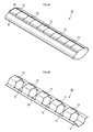
- FIG. 1A is a perspective view of a conductive member
- FIG. 1B is a perspective view of a metal part included in the conductive member
- 2A is a plan view of the conductive member
- FIG. 2B is a front view of the conductive member
- FIG. 2C is a right side view of the conductive member
- FIG. 2D is a sectional view taken along the line IID-IID of the conductive member
- FIG. FIG. Explanatory drawing which shows the use condition of an electroconductive member.
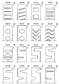
- 4A is a perspective view of a conductive member shown as a modified example
- FIG. 4B is a perspective view of a metal part provided in the conductive member shown as a modified example. Explanatory drawing which illustrates the form of various through-holes and notches.
- a conductive member 1 shown in FIGS. 1A-1B and 2A-2E is a member electrically connected between two members by being interposed between the two members, and a metal portion 3 formed of a metal material. And an elastomer part 5 formed of an elastomer material.
- the metal part 3 is formed by processing a metal foil having a thickness of 0.01 mm into a form as shown in FIG. 1B, and most of the metal part 3 is embedded in the elastomer part 5. Only a part of the part 3 is exposed to the outside of the elastomer part 5.
- a slit-like through hole 11 is formed in a strip-shaped metal foil, and convex parts 13 and 15 are formed with this through hole 11 being sandwiched.
- the convex part 13 is formed by bending one part of a pair of parts on both sides of the through hole 11 in the metal foil so as to protrude toward the surface side of the metal foil (see FIGS. 1B and 2D). ).
- the convex part 15 is formed by bending the other part of the pair of parts so as to protrude toward the back side of the metal foil (see FIGS. 1B and 2E).
- the through hole 11 is opened so as to form a substantially hexagonal opening (see FIG. 1B).
- the description will be continued with the protruding direction of the convex portion 13 being upward and the protruding direction of the convex portion 15 being downward for convenience.
- the upper and lower directions do not mean that the conductive member 1 should be used with the convex portion 13 facing upward in the usage state.
- the convex portion 13 has a metal flat surface portion 13A at the uppermost end of the metal portion 3 and a pair of side surface portions 13B that are connected to the metal flat surface portion 13A and extend downward. Then, a part of the upper end side of the metal flat surface portion 13 ⁇ / b> A and the pair of side surface portions 13 ⁇ / b> B is exposed to the outside of the elastomer portion 5, and the remaining portions of the pair of side surface portions 13 ⁇ / b> B are embedded in the elastomer portion 5.
- the convex portion 15 has a metal flat surface portion 15A at the lowermost end of the metal portion 3 and a pair of side surface portions 15B connected to the metal flat surface portion 15A and extending upward. Then, a part of the lower end side of the metal flat surface portion 15 ⁇ / b> A and the pair of side surface portions 15 ⁇ / b> B is exposed to the outside of the elastomer portion 5, and the remaining portions of the pair of side surface portions 15 ⁇ / b> B are embedded inside the elastomer portion 5.
- the metal flat surface portion 13A and the metal flat surface portion 15A are parallel surfaces, but the metal flat surface portion 13A and the metal flat surface portion 15A may not be parallel surfaces.
- the outline of the through hole 11 is not continuous with the outline of the metal foil. That is, the outline of the through-hole 11 is not a notch shape that is continuous with the outline of the metal foil.
- portions of the metal foil other than the pair of portions formed as the convex portions 13 and 15 form a pair of connecting portions 17.
- the pair of continuous portions 17 are connected to the convex portions 13 and 15 on both sides of the convex portions 13 and 15 that are in a line when viewed in plan.
- the end portion of the continuous portion 17 is exposed to the outside of the elastomer portion 5.
- the metal part 3 having the above-described form is formed by processing a metal foil in a mold prepared for molding the elastomer part 5. Specifically, a metal foil in which the through-holes 11 are formed in advance is arranged in the mold, and the jig is pushed up in the mold toward the projecting direction of the convex portions 13 and 15, thereby repairing the metal foil. The part which becomes the convex parts 13 and 15 at the tip of the tool is pushed out in the protruding direction.
- the elastomer part 5 is molded by subsequently injecting the raw material composition to be the elastomer part 5 into the mold.
- the metal part 3 is processed by such a processing method is arbitrary, and may be formed into an equivalent shape by other methods.
- the elastomer portion 5 is formed with elastomer plane portions 21 and 23 so as to be positioned on the same plane as the metal plane portions 13A and 15A. Moreover, in the elastomer part 5, the part which continues from the elastomer plane part 21 is provided with the inclination which becomes a downward gradient toward the end of the elastomer part 5, and it becomes a form in which an operator's fingertip etc. are not easily caught. Yes.
- the convex portion 15 is soldered to the printed wiring board 31, and another printed wiring board 33 contacts the convex portion 13.
- both printed wiring boards 31 and 33 can be electrically connected.
- both the metal flat surface portion 13A and the elastomer flat surface portion 21 are automatic mounting machines. Can be used as a suction surface for sucking the conductive member 1 with a suction nozzle.
- the elastomer flat portion 21 is a surface having a high coefficient of friction formed of an elastomer material, if the elastomer flat portion 21 is used as a suction surface, the conductive member 1 adsorbed by the suction nozzle is moved. In addition, it is possible to prevent the direction of the conductive member 1 from being changed due to an inertial force or the like.
- the elastomer flat portion 23 functions as a slip stopper when the conductive member 1 is disposed on the printed wiring board 31. Therefore, for example, even if vibration is transmitted to the printed wiring board 31 during the transfer in the reflow furnace in a state before the soldering is completed, the direction of the conductive member 1 is affected by such vibration. Can be prevented from changing.
- the height h of the portion where the solder fillet 35 is to be formed can be set to a height optimized in advance. Specifically, the height h of the portion where the solder fillet 35 is to be formed is set to a desired height according to the design of the mold for forming the elastomer portion 5.
- the conductive member 1 is a very small conductive member 1, the conductive member 1 is more than expected. There is a possibility that the flexibility of the conductive member 1 is impaired.
- the conductive member 1 is provided, by providing the elastomer portion 5, the height h of the portion where the solder fillet 35 is to be formed can be limited to the designed position, which is favorable. The flexibility of the conductive member 1 can be appropriately ensured while ensuring the bonding strength.
- the conductive member 1 when the conductive member 1 is sandwiched between the printed wiring boards 31 and 33 after completion of soldering, the conductive member 1 is compressed between the printed wiring boards 31 and 33 and receives the compression force. Elastically deforms. At this time, when the conductive member 1 is compressed in a direction in which the distance between the printed wiring boards 31 and 33 is narrowed, the conductive member 1 is deformed so as to swell in the direction of arrow P shown in FIG.
- the metal portion 3 has a shape in which the convex portion 15 forms a cylindrical shape of the lower half, but the upper half is open. Therefore, the elastomer portion 5 is not constrained over the entire circumference, and can be greatly deformed in the upper portion of the elastomer portion 5 as indicated by an arrow Q in FIG.
- the upper and lower sides are reversed from those in FIG. 3 and the convex portion 13 has a cylindrical shape of the upper half, but the lower half is in an open state. Further, only the connecting portion 17 exists at the boundary between the portion where the convex portion 13 is present and the portion where the convex portion 15 is present.
- the elastomer part 5 is only surrounded by the upper half or the lower half at most regardless of the cross section at any position in the arrangement direction of the convex parts 13 and 15. There is no place where the elastomer part 5 is surrounded all around.
- the elastomer portion 5 is not subjected to excessive distortion or excessive pressure, and the conductive member 1 is not damaged. It can be deformed smoothly.
- this invention is not limited to said specific one Embodiment, In addition, it can implement with a various form.
- an example in which the convex portion 13 projecting upward and the convex portion 15 projecting downward are provided one by one, but like the conductive member 51 illustrated in FIGS. 4A and 4B.
- a metal part 53 provided with a plurality of convex parts 13 projecting upward and convex parts 15 projecting downward may be embedded in the elastomer part 55 (in FIGS. 4A-4B, the convex parts 13 and Each of the convex portions 15 is provided by way of example by 5).
- the conductive member shown in FIGS. 1A-1B, 2A-2E and FIG. 3 is preferable to reduce the size. What is necessary is just to make an optimal number according to the objective. If a longer conductive member is required, such as when the conductive member is used as an electromagnetic shielding gasket, the repeating unit of the convex portion 13 and the convex portion 15 in the conductive member 51 illustrated in FIGS. 4A-4B is used. You may increase the number of repeating units more than a number.
- the same number of convex portions 13 projecting upward and convex portions 15 projecting downward are provided.
- two convex portions 13 projecting upward and projecting downward are provided.
- the number of convex portions 13 and 15 may be an odd number.
- the position of the metal flat surface portion 13A or the elastomer flat surface portion 21 used as the suction surface can be centered between both ends of the protruding portions in the arrangement direction.
- the stability of can be further improved.
- the metal part 3 and the metal part 53 shown by the said embodiment it was set as the form elongated in the direction perpendicular
- the form of the through hole may be another form.
- various forms of through-holes can be considered, such as metal foils 62 to 69 illustrated in FIGS. 5B-5I.
- metal foils with cutouts such as metal foils 70 to 75 illustrated in FIG. 5J-5O may be employed.
- the metal foils 61 to 69 having through holes have higher mechanical strength than the metal foils 70 to 75 having notches. It is preferable to select whether to provide a through hole or a notch in consideration of whether such strength is required.
- each of the metal foils 61 to 76 described above has a strip-like shape in which a through hole or a notch is provided, but whether or not to use a strip-like (rectangular) metal foil as a base is also arbitrary. .
Landscapes
- Engineering & Computer Science (AREA)
- Microelectronics & Electronic Packaging (AREA)
- Shielding Devices Or Components To Electric Or Magnetic Fields (AREA)
- Multi-Conductor Connections (AREA)
- Coupling Device And Connection With Printed Circuit (AREA)
Abstract
This conductive member is provided with a metal section and an elastomer section. The metal section is formed from a planar body of metal material, and is provided with at least one surface-side projection formed on the planar body so as to project to the surface side of the planar body, and at least one rear-surface-side protrusion formed on the planar body so as to project to the rear surface of the planar body. The conductive member is configured in such a manner that, with the conductive member oriented in such a manner that the tip of the at least one surface-side projection is in contact with a first member of a pair of members that hold the conductive member, and the tip of the at least one rear-surface-side protrusion is in contact with a second member of the pair of members, when the conductive member is sandwiched between the first member and the second member, the tip of the at least one surface-side projection is pressed toward the second member, and the tip of the at least one rear-surface-side protrusion is pressed toward the first member by elastically deforming the elastomer section.
Description
本国際出願は、2010年11月11日に日本国特許庁に出願された日本国特許出願第2010-253010号に基づく優先権を主張するものであり、日本国特許出願第2010-253010号の全内容を参照により本国際出願に援用する。
This international application claims priority based on Japanese Patent Application No. 2010-253010 filed with the Japan Patent Office on November 11, 2010. The entire contents are incorporated herein by reference.
本発明は、第一の部材と第二の部材との間に介装されることにより、第一の部材と第二の部材を電気的に接続する導電部材に関する。
The present invention relates to a conductive member that electrically connects the first member and the second member by being interposed between the first member and the second member.
第一の部材と第二の部材との間に介装されることにより、第一の部材と第二の部材を電気的に接続する導電部材として、第一の部材にはんだ付けされるとともに、第二の部材に対して接触するように配置されることにより、両部材間に導電経路を構成する導電部材が知られている。
As a conductive member that electrically connects the first member and the second member by being interposed between the first member and the second member, it is soldered to the first member, A conductive member that constitutes a conductive path between both members by being disposed so as to be in contact with the second member is known.
このような導電部材の代表的な例としては、例えば、金属の薄板から打ち抜かれた部品を折り曲げて形成された導電部材を挙げることができる(例えば、特許文献1参照。)。この種の板金製の部材は、一般にばね性のある金属材で形成されており、例えば、第一の部材であるプリント配線板に表面実装され、第二の部材である別のプリント配線板、シールド板、あるいはシャーシなどと第一の部材とを導通させるのに利用される。
As a typical example of such a conductive member, for example, a conductive member formed by bending a part punched from a metal thin plate can be cited (for example, see Patent Document 1). This kind of sheet metal member is generally formed of a spring metal material, for example, surface-mounted on a printed wiring board as a first member, another printed wiring board as a second member, This is used to connect the shield plate or chassis to the first member.
また、上記のような表面実装部品とは異なる形態の導電部材としては、より長尺な形態に構成された導電部材も知られている。このような導電部材の代表的な例としては、第一の部材と第二の部材の隙間から漏洩又は侵入する電磁波を抑制する電磁波シールド用ガスケットとして利用される導電部材を挙げることができる(例えば、特許文献2参照。)。
Also, as a conductive member having a different form from the above-described surface-mounted component, a conductive member configured in a longer form is also known. As a typical example of such a conductive member, a conductive member used as an electromagnetic shielding gasket that suppresses electromagnetic waves leaking or entering from a gap between the first member and the second member can be exemplified (for example, , See Patent Document 2).
このような電磁波シールド用ガスケットは、例えば、単位構造が一軸方向に繰り返し形成された長尺材として構成されるが、これもばね性のある金属材で形成されている。
Such an electromagnetic shielding gasket is configured as a long material in which a unit structure is repeatedly formed in a uniaxial direction, for example, and is also formed of a metal material having a spring property.
ところで、携帯電話などのモバイル機器においては、きわめて小型化・軽量化が進んでいるため、プリント配線板と筐体との隙間がきわめて狭くなっている。そのため、このような隙間に導電部材を配設してプリント配線板と筐体を電気的に接続する際には、きわめて小型の導電部材、特に高さ方向寸法がきわめて小さい低背型の導電部材が必要となる。
By the way, in mobile devices such as mobile phones, since the miniaturization and weight reduction are progressing, the gap between the printed wiring board and the housing is extremely narrow. Therefore, when a conductive member is disposed in such a gap and the printed wiring board and the housing are electrically connected, an extremely small conductive member, particularly a low profile conductive member having a very small height dimension. Is required.
しかし、上記特許文献1に記載された導電部材のように、金属板を折り返すように曲げてばね部を形成した構造になっている導電部材では、高さ方向寸法がごく小さくなるように、その導電部材を加工する場合、はんだ接合部に対して略V字状にばね部を折り返す際に、過剰に小さいアールでばね部を折り返さざるを得なくなる。そのため、この導電部材では、そのような無理な折り返しによって、ばね部が折り返し部分で折れやすくなってしまう傾向があった。
However, in the conductive member having a structure in which the spring portion is formed by bending the metal plate like the conductive member described in Patent Document 1, the dimension in the height direction is extremely small. When processing the conductive member, when the spring portion is folded back in a substantially V shape with respect to the solder joint portion, the spring portion must be folded back with an excessively small radius. For this reason, in this conductive member, the spring portion tends to be easily broken at the folded portion due to such an excessive folding.
また、上記のように折り返し部分の谷折り箇所が鋭角をなすかたちで略V字状に折り返す代わりに、折り返し部分の谷折り箇所が鈍角をなすかたちで金属板の一部を切り上げて、その切り上げ部分を他の部分に接触させる構造になっている導電部材もある。しかし、このような切り上げばねは、ばね性に劣り、復元性が良くないため、あまり大きなストロークを確保することはできず、十分に高い接触圧を確保することは難しい、といった問題があった。
In addition, instead of turning back into a substantially V shape in the form of a valley fold in the folded part as described above, a part of the metal plate is rounded up so that the valley fold in the folded part forms an obtuse angle, There is also a conductive member having a structure in which the rounded-up portion is brought into contact with another portion. However, such a round-up spring has a problem in that it is difficult to ensure a sufficiently high contact pressure because it is inferior in spring property and has poor resilience, so that a very large stroke cannot be ensured.
さらに、上記特許文献2に記載された電磁波シールド用ガスケットにおいても、金属材のばね性を確保できる範囲内でしか小型化ができないため、高さ方向寸法や幅方向寸法がきわめて小さいガスケットを構成することは容易ではない、という問題があった。
Furthermore, the electromagnetic shielding gasket described in Patent Document 2 can be downsized only within a range in which the spring property of the metal material can be ensured, so that a gasket having extremely small height and width dimensions is formed. There was a problem that it was not easy.
一方、上記のような金属製の導電部材以外には、例えば、弾性体を芯材にして、その周囲に導電布や導電性フィルムを巻き付けた構造とされた導電部材も提案されている。しかし、このような構造の導電部材は、弾性体が全周にわたって導電布や導電性フィルムによって拘束されている状態にある。そのため、この種の導電部材が二部材間に挟み込まれた際には、変形した弾性体の逃げ場所がなく、弾性体から導電布や導電性フィルムに作用する圧力が過剰に高くなりやすいので、導電布や導電性フィルムに過大な負荷がかかってしまう、という問題があった。
On the other hand, in addition to the metal conductive member as described above, for example, a conductive member having a structure in which an elastic body is used as a core and a conductive cloth or a conductive film is wound around the elastic member has been proposed. However, the conductive member having such a structure is in a state where the elastic body is restrained by the conductive cloth or the conductive film over the entire circumference. Therefore, when this type of conductive member is sandwiched between two members, there is no escape location of the deformed elastic body, and the pressure acting on the conductive cloth and conductive film from the elastic body tends to be excessively high. There was a problem that an excessive load was applied to the conductive cloth and the conductive film.
本発明は、上記問題を解決するためになされたものであり、その目的は、小型化した場合でも十分に高い接触圧を発揮させることができ、二部材間に挟み込まれた際に導電部分に過大な負荷がかかることが抑制された導電部材を提供することにある。
The present invention has been made in order to solve the above-described problem, and the purpose thereof is to allow a sufficiently high contact pressure to be exerted even when the device is miniaturized, and when the conductive portion is sandwiched between two members. An object of the present invention is to provide a conductive member in which an excessive load is suppressed.
以下、本発明において採用した構成について説明する。
本発明の第1局面における導電部材は、金属部と、エラストマー部とを備える。金属部は、金属材料の面状体から形成され、該面状体の表面側へ突出するように該面状体に形成される少なくとも一つの表面側凸部と、該面状体の裏面側へ突出するように該面状体に形成される少なくとも一つの裏面側凸部とを備える。少なくとも一つの表面側凸部は、面状体に少なくとも一つの貫通孔及び少なくとも一つの切欠きのうちの少なくとも一方を形成して、該少なくとも一つの貫通孔及び該少なくとも一つの切欠きのうちの該少なくとも一方を挟んで両側に位置する面状体の一対の部分のうちの一方の部分を面状体の表面側へ突出するように曲げることにより形成されている。少なくとも一つの裏面側凸部は、面状体の一対の部分のうちの他方の部分を面状体の裏面側へ突出するように曲げることにより形成されている。エラストマー部は、エラストマー材料を含み、少なくとも一つの表面側凸部の先端部分と少なくとも一つの裏面側凸部の先端部分とを外部に露出させた状態で金属部を埋設している。導電部材は、少なくとも一つの表面側凸部の先端部分が、導電部材が挟持される一対の部材のうちの第一の部材に接するとともに、少なくとも一つの裏面側凸部の先端部分が、一対の部材のうちの第二の部材に接するように導電部材が配向された状態で、導電部材が第一の部材と第二の部材との間に挟み込まれた際に、エラストマー部が弾性変形することによって、少なくとも一つの表面側凸部の先端部分が第二の部材側に向かって押圧されるとともに、少なくとも一つの裏面側凸部の先端部分が第一の部材側に向かって押圧されるように構成されている。 Hereinafter, the configuration employed in the present invention will be described.
The conductive member according to the first aspect of the present invention includes a metal portion and an elastomer portion. The metal part is formed of a planar body of a metal material, and has at least one surface-side convex part formed on the planar body so as to protrude to the front surface side of the planar body, and the back surface side of the planar body And at least one rear surface-side convex portion formed on the planar body so as to protrude to the rear. The at least one surface-side convex portion forms at least one of at least one through hole and at least one notch in the planar body, and the at least one through hole and the at least one notch It is formed by bending one portion of a pair of portions of the planar body located on both sides with at least one of them sandwiched so as to protrude to the surface side of the planar body. The at least one back surface convex portion is formed by bending the other portion of the pair of portions of the planar body so as to protrude toward the back surface side of the planar body. The elastomer part includes an elastomer material and embeds the metal part in a state in which the tip part of at least one front side convex part and the tip part of at least one back side convex part are exposed to the outside. The conductive member has a tip portion of at least one front side convex portion in contact with a first member of a pair of members between which the conductive member is sandwiched, and a tip portion of at least one back side convex portion has a pair of The elastomer portion is elastically deformed when the conductive member is sandwiched between the first member and the second member in a state where the conductive member is oriented so as to contact the second member of the members. As a result, the front end portion of at least one front side convex portion is pressed toward the second member side, and the front end portion of at least one rear surface side convex portion is pressed toward the first member side. It is configured.
このように構成された導電部材では、少なくとも一つの表面側凸部と少なくとも一つの裏面側凸部とのうちの一方が第一の部材と第二の部材とのうちの一方にはんだ付けされて、少なくとも一つの表面側凸部と少なくとも一つの裏面側凸部とのうちの他方が第一の部材と第二の部材とのうちの他方に接触するように配置される。あるいは、少なくとも一つの表面側凸部と少なくとも一つの裏面側凸部とがそれぞれ、第一の部材又は第二の部材のいずれかに接触するように配置される。すなわち、この導電部材は、配設箇所にはんだ付けすることもできるし、はんだ付けすることなく配設することも可能である。
In the conductive member configured as described above, one of the at least one front surface convex portion and the at least one back surface convex portion is soldered to one of the first member and the second member. The other of the at least one front surface convex portion and the at least one back surface convex portion is arranged so as to contact the other of the first member and the second member. Or at least 1 surface side convex part and at least 1 back surface side convex part are arrange | positioned so that either the 1st member or the 2nd member may contact, respectively. In other words, the conductive member can be soldered to the place where it is placed, or can be placed without soldering.
このような導電部材が第一の部材と第二の部材との間に挟み込まれると、エラストマー部が弾性変形することにより、金属部に設けられた少なくとも一つの表面側凸部の先端部分は、第二の部材側に向かって押圧され、金属部に設けられた少なくとも一つの裏面側凸部の先端部分は、第一の部材側に向かって押圧された状態になる。
When such a conductive member is sandwiched between the first member and the second member, the elastomer portion is elastically deformed, so that the tip portion of at least one surface side convex portion provided in the metal portion is The tip portion of at least one rear surface convex portion provided on the metal portion is pressed toward the second member side, and is in a state of being pressed toward the first member side.
したがって、少なくとも一つの表面側凸部が第一の部材と接触するように配置された箇所と、少なくとも一つの裏面側凸部が第二の部材と接触するように配置された箇所とにおいては、少なくとも一つの表面側凸部が第一の部材に対して適切な接触圧で圧接し、少なくとも一つの裏面側凸部が第二の部材に対して適切な接触圧で圧接する状態になるので、金属ばねを利用した導電部材とは異なり、本発明に係る導電部材を小型化した場合でも、本発明に係る導電部材は十分に高い接触圧を発揮することができる。
Therefore, at a location where at least one front side convex portion is arranged to contact the first member and at a location where at least one back side convex portion is arranged to contact the second member, Since at least one front surface side convex portion is pressed against the first member with an appropriate contact pressure, and at least one back surface side convex portion is pressed against the second member with an appropriate contact pressure, Unlike a conductive member using a metal spring, even when the conductive member according to the present invention is miniaturized, the conductive member according to the present invention can exhibit a sufficiently high contact pressure.
また、少なくとも一つの表面側凸部及び少なくとも一つの裏面側凸部は、金属材料の面状体に少なくとも一つの貫通孔及び少なくとも一つの切欠きのうちの少なくとも一方を形成し、少なくとも一つの貫通孔及び少なくとも一つの切欠きのうちの少なくとも一方を挟んで両側に位置する面状体の一対の部分のうちの一方の部分を面状体の表面側へ突出するように曲げるとともに、面状体の一対の部分のうちの他方の部分を面状体の裏面側へ突出するように曲げることによって形成されている。
Further, the at least one front side convex portion and the at least one back side convex portion form at least one of at least one through hole and at least one notch in the planar body of the metal material, and at least one through portion is formed. While bending at least one of the pair of portions of the planar body located on both sides of at least one of the hole and at least one notch so as to protrude toward the surface side of the planar body, the planar body The other part of the pair of parts is bent so as to protrude toward the back side of the planar body.
そのため、各凸部の突出方向には金属部分があるものの、その突出方向とは反対側の方向には金属部分が存在しない構造になっている。したがって、少なくとも一つの表面側凸部が第一の部材に圧接し、少なくとも一つの裏面側凸部が第二の部材に圧接した際に弾性変形することになるエラストマー部は、各凸部の突出方向とは反対側において比較的自由に変形できる。
Therefore, although there is a metal portion in the protruding direction of each convex portion, there is no metal portion in the direction opposite to the protruding direction. Therefore, the elastomer portion that is elastically deformed when at least one front surface convex portion is in pressure contact with the first member and at least one back surface convex portion is in pressure contact with the second member is a protrusion of each convex portion. It can be deformed relatively freely on the side opposite to the direction.
よって、エラストマー部が全周にわたって導電布や導電性フィルムで拘束されている導電部材とは異なり、エラストマー部から各凸部の内側に過大な圧力がかかるのを抑制でき、また、第一の部材及び第二の部材における接触箇所に対する追従性が良好な変形を実現することができる。
Therefore, unlike the conductive member in which the elastomer portion is constrained by the conductive cloth or conductive film over the entire circumference, it is possible to suppress excessive pressure from being applied to the inside of each convex portion from the elastomer portion, and the first member And the deformation | transformation with favorable followable | trackability with respect to the contact location in a 2nd member is realizable.
なお、以上のような導電部材を構成するに当たって、金属部を構成する金属材料としては、導電性に優れた各種金属を用いることができ、例えば、金、銀、銅、アルミニウム、その他の各種合金(例えば、ステンレス、りん青銅、ベリリウム銅など)を用いることができる。これらの金属材料は、性能だけを考慮すれば導電性の高いものほど好ましいが、コスト面なども考慮した上で、好適なものを適宜選択すればよい。
In forming the conductive member as described above, various metals having excellent conductivity can be used as the metal material constituting the metal part, for example, gold, silver, copper, aluminum, and other various alloys. (For example, stainless steel, phosphor bronze, beryllium copper, etc.) can be used. As for these metal materials, a material having higher conductivity is preferable in consideration of only performance, but a suitable material may be appropriately selected in consideration of cost.
また、エラストマー材料としては、例えば、各種ゴム、ゴム弾性を有する熱可塑性エラストマー、多数の高分子が鎖の上の特定部分の結合により互いに部分的につながってできた三次元網目状構造を持つゲル等が用いられる。
Examples of the elastomer material include various rubbers, thermoplastic elastomers having rubber elasticity, and gels having a three-dimensional network structure in which a large number of polymers are partially connected to each other by bonding of specific portions on the chain. Etc. are used.
上記のゴムとしては、天然ゴム、イソプレンゴム、ブタジエン・スチレンゴム、ブタジエン・アクリロニトリルゴム、ブチルゴム、クロロプレンゴム、エチレン・酢ビゴム、多硫化物系ゴム、ウレタンゴム、エチレンプロピレンゴム、エチレン・プロピレン・ターポリマー、ガタパーチャ、クロロスルホン化ポリエチレン、シリコーンゴム、ブタジエンゴム、ふっ素ゴム、ポリイソブチレン、アクリルゴム等が例示される。
The above rubbers include natural rubber, isoprene rubber, butadiene / styrene rubber, butadiene / acrylonitrile rubber, butyl rubber, chloroprene rubber, ethylene / vinyl acetate rubber, polysulfide rubber, urethane rubber, ethylene propylene rubber, ethylene / propylene rubber, Examples thereof include polymers, gutta percha, chlorosulfonated polyethylene, silicone rubber, butadiene rubber, fluorine rubber, polyisobutylene, and acrylic rubber.
上記の熱可塑性エラストマーとしては、スチレンブロック共重合体(SBC)、サーモポリオレフィン(TPO)、熱可塑性ポリウレタン(TPU)、熱可塑性加硫エラストマー(TPV)等が例示される。
Examples of the thermoplastic elastomer include styrene block copolymer (SBC), thermopolyolefin (TPO), thermoplastic polyurethane (TPU), and thermoplastic vulcanized elastomer (TPV).
上記のゲルとしては、三次元網目状構造を持つベースポリマーの網目組織の間隙に軟化剤(例えばオイル成分)を包含して流動性を失った状態にしたゲルが好適である。
そのベースポリマーとしては、例えば、スチレン系(イソプレン-スチレン系(SIS系)、エチレン-プロピレン-スチレン系(SEPS系)、エチレン-ブタジエン-スチレン系(SEBS系)、オレフィン系、エステル系、アミド系、ウレタン系などの各種熱可塑性エラストマー、並びに、これらの水添、その他による変成物、あるいは、スチレン系、ABS系、オレフィン系、塩化ビニル系、アクリル系、カーボネート系、アセタール系、ナイロン系、ハロゲン化オレフィン系(四フッ化エチレン系、フッ化-塩化エチレン系、フッ化エチレンプロピレン系など)、セルロース系(エチルセルロース系など)の熱可塑性樹脂、及びこれらの樹脂のゴム変成物などが挙げられる。なお、これらの各種熱可塑性樹脂は、単独で用いても、2種以上をブレンドして用いてもよい。 As the gel, a gel in which the fluidity is lost by including a softening agent (for example, an oil component) in the gaps in the network structure of the base polymer having a three-dimensional network structure is preferable.
Examples of the base polymer include styrene (isoprene-styrene (SIS), ethylene-propylene-styrene (SEPS), ethylene-butadiene-styrene (SEBS), olefin, ester, and amide. , Urethane-based thermoplastic elastomers, and their hydrogenated and other modified products, or styrene-based, ABS-based, olefin-based, vinyl chloride-based, acrylic-based, carbonate-based, acetal-based, nylon-based, halogen Olefin-based (tetrafluoroethylene-based, fluorinated-ethylene chloride-based, fluorinated ethylenepropylene-based, etc.), cellulose-based (ethylcellulose-based, etc.) thermoplastic resins, and rubber modified products of these resins. In addition, even if these various thermoplastic resins are used independently, It may be used as a blend of the above species.
軟化剤としては、鉱物油系、植物油系、合成系などの各種ゴム用又は樹脂用軟化剤が挙げられる。鉱物油系としては、パラフィン系、ナフテン系、アロマ系などのプロセスオイルが挙げられ、植物油系としては、ひまし油、綿実油、亜麻仁油、菜種油、大豆油、パーム油、椰子油、落花生油、木蝋、パインオイル、オリーブ油などが挙げられる。これらの軟化剤は単独で用いても良いが、互いの相溶性が良好な2種以上を混合させて用いてもよい。なお、軟化剤の添加量が多いほどゲルの硬度は低くなるので、所望の硬度となるように調製すればよい。
Examples of softeners include various rubber or resin softeners such as mineral oil, vegetable oil, and synthetic. Examples of mineral oils include paraffinic, naphthenic, and aromatic process oils, and vegetable oils include castor oil, cottonseed oil, linseed oil, rapeseed oil, soybean oil, palm oil, coconut oil, peanut oil, wood wax, Examples include pine oil and olive oil. These softeners may be used alone or in combination of two or more having good compatibility with each other. In addition, since the hardness of a gel becomes so low that there is much addition amount of a softening agent, what is necessary is just to prepare so that it may become desired hardness.
また、ベースポリマー及び軟化剤のほか、諸特性の改良のため、公知の樹脂成分などの添加剤を併用することができる。樹脂成分としては、例えば、ポリオレフィン樹脂やポリスチレン樹脂などを併用することができる。これらを添加することにより加工性、耐熱性の向上を図ることができる。ポリオレフィン樹脂としては、例えば、ポリエチレン、アイソタクティックポリプロピレン、プロピレンと他の少量のα-オレフィンとの共重合体(例えば、プロピレン-エチレン共重合体、プロピレン/4-メチル-1-ペンテン共重合体)、ポリ(4-メチル-1-ペンテン)、ポリブテン-1等を挙げることができる。
In addition to the base polymer and softener, additives such as known resin components can be used in combination for improving various properties. As the resin component, for example, a polyolefin resin or a polystyrene resin can be used in combination. By adding these, workability and heat resistance can be improved. Examples of the polyolefin resin include polyethylene, isotactic polypropylene, and a copolymer of propylene and a small amount of other α-olefin (for example, propylene-ethylene copolymer, propylene / 4-methyl-1-pentene copolymer). ), Poly (4-methyl-1-pentene), polybutene-1, and the like.
さらに、他の添加剤として、必要に応じて、抗菌剤、ヒンダードアミン系光安定剤、紫外線吸収剤、酸化防止剤、無機充填剤、着色剤、シリコーンオイル、クマロン樹脂、クマロン-インデン樹脂、フェノールテルペン樹脂、石油系炭化水素、ロジン誘導体等の各種粘着付与剤(タッキファイヤー)を併用することができる。
Furthermore, as other additives, antibacterial agents, hindered amine light stabilizers, ultraviolet absorbers, antioxidants, inorganic fillers, colorants, silicone oils, coumarone resins, coumarone-indene resins, phenol terpenes as necessary. Various tackifiers (tackifiers) such as resins, petroleum hydrocarbons, and rosin derivatives can be used in combination.
さらに、リフローはんだ付けで表面実装可能な導電部材を構成する場合には、エラストマー材料はリフロー工程に耐え得る物性を備えた材質であることを要求される。実施にあたっては、上に例示したゴム、エラストマー、ゲル等でリフロー工程に耐え得る材質を選択して使用すればよい。リフロー工程で要求される耐熱条件は、任意に設定し得るが、一般的な条件の一例としては、例えば240℃以下、5秒以下といった条件を挙げることができる。
Furthermore, when a conductive member that can be surface-mounted by reflow soldering is configured, the elastomer material is required to be a material having physical properties that can withstand the reflow process. In implementation, a material that can withstand the reflow process such as rubber, elastomer, and gel exemplified above may be selected and used. The heat-resistant conditions required in the reflow process can be arbitrarily set, but examples of general conditions include conditions such as 240 ° C. or less and 5 seconds or less.
本発明における導電部材では、少なくとも一つの表面側凸部及び少なくとも一つの裏面側凸部は、面状体の表面及び裏面に垂直な方向から見て、一列に並んで形成されてもよい。
In the conductive member according to the present invention, the at least one front side convex portion and the at least one back side convex portion may be formed in a line when viewed from a direction perpendicular to the front surface and the back surface of the planar body.
このような導電部材は、少なくとも一つの表面側凸部と少なくとも一つの裏面側凸部とが一列に並ぶので、凸部の個数に応じた長さを持つ線状の導電部材となる。したがって、凸部の個数を少なめにすることで、自動実装用の導電部材として利用することもでき、あるいは、凸部の個数を十分に多めにすることで、導電性ガスケットとして利用される導電部材を構成することもできる。
Such a conductive member is a linear conductive member having a length corresponding to the number of convex portions since at least one front side convex portion and at least one back side convex portion are arranged in a line. Therefore, by reducing the number of convex portions, it can be used as a conductive member for automatic mounting, or by sufficiently increasing the number of convex portions, a conductive member used as a conductive gasket. Can also be configured.
本発明における導電部材では、面状体には、少なくとも一つの貫通孔が形成されてもよく、面状体における、少なくとも一つの表面側凸部及び少なくとも一つの裏面側凸部以外の部分は、少なくとも一つの表面側凸部と少なくとも一つの裏面側凸部とが並ぶ方向と交差する方向の両端部において該少なくとも一つの表面側凸部と該少なくとも一つの裏面側凸部とに連設された一対の連設部を形成してもよい。
In the conductive member of the present invention, at least one through-hole may be formed in the planar body, and the portion other than the at least one front side convex portion and the at least one back side convex portion in the planar body, At least one front surface side convex portion and at least one back surface side convex portion are connected to the at least one front surface side convex portion and the at least one back surface side convex portion at both ends in a direction intersecting the direction in which the at least one front surface side convex portion is aligned. A pair of continuous portions may be formed.
このように構成された導電部材では、導電部材を少なくとも一つの表面側凸部と少なくとも一つの裏面側凸部との列設方向へ引っ張るような力が導電部材に作用したとしても、一対の連設部のうちの少なくとも一方が破断しない限り、貫通孔の幅が拡大することはなく、導電部材が貫通孔部分で分断されるのを抑制することができる。
In the conductive member configured as described above, even if a force that pulls the conductive member in the direction in which the at least one front-side convex portion and the at least one rear-side convex portion are arranged on the conductive member is applied, As long as at least one of the installed portions is not broken, the width of the through hole is not increased, and the conductive member can be prevented from being divided at the through hole portion.
本発明における導電部材は、第一の部材と第二の部材との間に挟み込まれた際に、金属部及びエラストマー部の変形に伴って、一対の連設部が互いに離間する方向へ移動するように構成されてもよい。
When the conductive member according to the present invention is sandwiched between the first member and the second member, the pair of connected portions move in a direction away from each other with the deformation of the metal portion and the elastomer portion. It may be configured as follows.
このように構成された導電部材では、一対の連設部が互いに離間する方向へ移動すると、金属部の形態が少なくとも一つの表面側凸部と少なくとも一つの裏面側凸部とを形成する前の面状体に近づき、金属部の変形量は減少することになる。したがって、金属部の変形量が増大する場合に比べ、金属部にかかる負荷を軽減することができる。
In the conductive member configured as described above, when the pair of continuous portions move in a direction away from each other, the shape of the metal portion is before the at least one front side convex portion and at least one back side convex portion are formed. The amount of deformation of the metal part decreases as it approaches the planar body. Therefore, compared with the case where the deformation amount of the metal part increases, the load on the metal part can be reduced.
本発明における導電部材では、金属部は、第一の部材と第二の部材との間に挟み込まれたエラストマー部が弾性変形した際に、当該エラストマー部の形態に追従するかたちで塑性変形する金属箔から形成されてもよい。
In the conductive member of the present invention, the metal part is a metal that plastically deforms in a manner that follows the form of the elastomer part when the elastomer part sandwiched between the first member and the second member is elastically deformed. It may be formed from foil.
このように構成された導電部材では、金属部がエラストマー部の形態に追従するかたちで塑性変形する金属箔から形成されているので、金属部そのものにばね性を持たせることは困難である。しかしながら、エラストマー部が弾性変形することで、金属箔から形成された金属部もエラストマー部の形態に追従するかたちで塑性変形する。したがって、このような構造になっていれば、ばね性が発現するような機械的強度の高い金属材で金属部を形成しなくても済むので、きわめて容易に導電部材の小型化を実現することができ、低背型の自動実装部品や導電性ガスケットを構成するのに好適である。
In the conductive member configured as described above, since the metal part is formed of a metal foil that is plastically deformed following the form of the elastomer part, it is difficult to give the metal part itself springiness. However, when the elastomer part is elastically deformed, the metal part formed from the metal foil is also plastically deformed following the form of the elastomer part. Therefore, with such a structure, it is not necessary to form the metal portion with a metal material having high mechanical strength that exhibits springiness, so that the conductive member can be miniaturized very easily. It is suitable for constructing low-profile automatic mounting parts and conductive gaskets.
本発明における導電部材では、少なくとも一つの表面側凸部の先端部分と少なくとも一つの裏面側凸部の先端部分との各々に、平面状に形成された金属平面部が設けられてもよく、少なくとも一つの表面側凸部の金属平面部と、少なくとも一つの裏面側凸部の金属平面部とが互いに平行になっていてもよい。
In the conductive member of the present invention, each of the tip portion of the at least one front side convex portion and the tip portion of the at least one back side convex portion may be provided with a flat metal surface portion, The metal flat surface portion of one front surface side convex portion and the metal flat surface portion of at least one back surface side convex portion may be parallel to each other.
このように構成された導電部材では、少なくとも一つの表面側凸部先端の金属平面部と少なくとも一つの裏面側凸部先端の金属平面部とが互いに平行になっているので、導電部材が平行な一対の面間に挟み込まれる場合に、それら平行な一対の面の双方と導電部材とが適切に接触することができる。
In the conductive member configured in this way, the metal flat portion at the tip of at least one front surface convex portion and the metal flat portion at the tip of at least one back surface convex portion are parallel to each other. When sandwiched between the pair of surfaces, both of the parallel pair of surfaces and the conductive member can appropriately come into contact.
また、導電部材が自動実装部品として構成される場合には、表面側にある凸部先端の金属平面部と裏面側にある凸部先端の金属平面部のうち、一方をはんだ接合面として利用し、他方を自動実装機の吸引ノズルで吸着するための吸着面として利用することができる。
In addition, when the conductive member is configured as an automatic mounting component, one of the metal flat part at the front end of the convex part on the front side and the metal flat part at the front end of the convex part on the back side is used as a solder joint surface. The other can be used as a suction surface for sucking with the suction nozzle of the automatic mounting machine.
本発明における導電部材では、エラストマー部には、少なくとも一つの表面側凸部の金属平面部と、少なくとも一つの裏面側凸部の金属平面部との一方に対して同一平面上に位置するように、少なくとも一つのエラストマー平面部が形成されていてもよい。
In the conductive member according to the present invention, the elastomer portion is positioned on the same plane with respect to one of the metal plane portion of the at least one front side convex portion and the metal plane portion of the at least one back side convex portion. At least one elastomer plane portion may be formed.
このように構成された導電部材によれば、所定の設置場所に導電部材を配置した際、その配置場所に少なくとも一つの表面側凸部の金属平面部と少なくとも一つの裏面側凸部の金属平面部とのうちの少なくとも一方が接する状態になると、少なくとも一つの表面側凸部の金属平面部と少なくとも一つの裏面側凸部の金属平面部とのうちの少なくとも一方とともに、少なくとも一つのエラストマー平面部も配置場所に接する状態となる。そのため、これら金属平面部よりも表面の摩擦抵抗が大となるエラストマー平面部が滑り止めとしての役割を果たす。
According to the conductive member configured in this manner, when the conductive member is disposed at a predetermined installation location, the metal plane portion of at least one front side convex portion and the metal plane portion of at least one back side convex portion are disposed at the placement location. And at least one of the metal flat portion of at least one front surface side convex portion and at least one of the metal flat surface portion of at least one back surface side convex portion when at least one of them is in contact with at least one elastomer flat surface portion Is also in contact with the location. For this reason, the elastomer flat portion having a higher surface frictional resistance than the metal flat portion plays a role as an anti-slip.
したがって、このような導電部材では、僅かな外力を受けたことが原因で導電部材の向きが変わってしまうのを抑制できる。このため、このような導電部材は、小型の自動実装部品として好適となり得る。また、このような導電部材を長尺な導電性ガスケットとして構成した場合には、金属製の導電部材よりも、配置作業中の位置ずれが抑制されるので、このように構成された導電部材は、作業性の良好な導電性ガスケットとなり得る。
Therefore, in such a conductive member, it is possible to prevent the direction of the conductive member from changing due to receiving a slight external force. For this reason, such a conductive member can be suitable as a small automatic mounting component. Further, when such a conductive member is configured as a long conductive gasket, since the displacement during the placement work is suppressed as compared with the metal conductive member, the conductive member configured in this way is It can be a conductive gasket with good workability.
本発明における導電部材では、少なくとも一つの表面側凸部と少なくとも一つの裏面側凸部とのうちの少なくとも一方は、少なくとも一つの表面側凸部と少なくとも一つの裏面側凸部とのうちの少なくとも一方の金属平面部を挟む両側の位置に連設された一対の側面部を有するように形成されてもよく、一対の側面部は、当該一対の側面部における金属平面部から連続する一部がエラストマー部の外部に露出する一方、当該一対の側面部における残りの部分がエラストマー部の内部に埋設されていてもよい。
In the conductive member of the present invention, at least one of the at least one front side convex portion and the at least one back side convex portion is at least one of the at least one front side convex portion and the at least one back side convex portion. It may be formed so as to have a pair of side surface portions that are continuously provided at positions on both sides sandwiching one metal plane portion, and the pair of side surface portions has a portion that continues from the metal plane portion in the pair of side surface portions. While exposed to the outside of the elastomer portion, the remaining portions of the pair of side surface portions may be embedded in the elastomer portion.
このように構成された導電部材によれば、金属平面部を挟む両側の位置に一対の側面部が連設され、その一対の側面部の一部がエラストマー部の外部に露出しているので、一対の側面部が形成された凸部をはんだ付けする際には、一対の側面部にはんだフィレットが形成される。しかも、この一対の側面部において、エラストマー部の外部に露出する部分は、その露出範囲を所望の範囲に調節することができるので、過剰にはんだが濡れ上がらない程度に調節することができる。
According to the conductive member configured in this way, a pair of side surface portions are continuously provided at positions on both sides sandwiching the metal flat surface portion, and a part of the pair of side surface portions is exposed to the outside of the elastomer portion. When soldering the convex portions formed with the pair of side surface portions, solder fillets are formed on the pair of side surface portions. In addition, in the pair of side surface portions, the portions exposed to the outside of the elastomer portion can be adjusted to a desired range, so that the solder can be adjusted to an extent that the solder does not get wet excessively.
したがって、このように構成された導電部材では、はんだフィレットが形成されない形態になっている導電部材に比べ、はんだ付けされた箇所の接合強度を向上させることができる。また、過剰にはんだが濡れ上がって比較的大きいはんだフィレットが形成される導電部材とも異なり、剛性の高いはんだフィレットの形成に伴って導電部材の柔軟性が損なわれてしまうこともなく、特に小型化された導電部材において、導電部材のサイズに見合う最適なサイズのはんだフィレットが形成されるように調節することが可能となる。
Therefore, in the conductive member configured as described above, the bonding strength of the soldered portion can be improved as compared with the conductive member in which the solder fillet is not formed. Also, unlike conductive members where solder is excessively wetted and a relatively large solder fillet is formed, the flexibility of the conductive member is not spoiled with the formation of a highly rigid solder fillet, and the size is particularly reduced. In the conductive member thus formed, it is possible to adjust so as to form a solder fillet having an optimum size corresponding to the size of the conductive member.
本発明の第2局面は、導電部材を製造する方法であって、金属材料の面状体に少なくとも一つの貫通孔及び少なくとも一つの切欠きのうちの少なくとも一方を形成する工程と、少なくとも一つの貫通孔及び少なくとも一つの切欠きのうちの少なくとも一方を挟んで両側に位置する面状体の一対の部分のうちの一方の部分を面状体の表面側へ突出するように曲げることにより、少なくとも一つの表面側凸部を形成する工程と、面状体の一対の部分のうちの他方の部分を面状体の裏面側へ突出するように曲げることにより、少なくとも一つの裏面側凸部を形成する工程と、少なくとも一つの表面側凸部の先端部分と少なくとも一つの裏面側凸部の先端部分とを外部に露出させた状態で面状体をエラストマー材料に埋設する工程とを備える。
A second aspect of the present invention is a method of manufacturing a conductive member, the method comprising forming at least one of at least one through hole and at least one notch in a planar body of a metal material, and at least one Bending at least one of the pair of portions of the planar body located on both sides across at least one of the through hole and the at least one notch so as to protrude toward the surface side of the planar body, Forming at least one back side convex part by bending the other part of the step of forming one front side convex part and the other part of the pair of parts of the planar body toward the back side of the planar body And a step of embedding the planar body in the elastomer material in a state in which a tip portion of at least one front side convex portion and a tip portion of at least one back side convex portion are exposed to the outside.
このような方法によれば、小型化した場合でも十分に高い接触圧を発揮させることができ、二部材間に挟み込まれた際に導電部分に過大な負荷がかかることが抑制された導電部材を提供することができる。
According to such a method, a conductive member capable of exerting a sufficiently high contact pressure even when downsized and suppressing an excessive load on the conductive portion when sandwiched between the two members is provided. Can be provided.
1,51・・・導電部材、3・・・金属部、5・・・エラストマー部、11・・・貫通孔、13,15・・・凸部、13A,15A・・・金属平面部、13B,15B・・・側面部、17・・・連設部、21,23・・・エラストマー平面部、31,33・・・プリント配線板、61~76・・・金属箔
DESCRIPTION OF SYMBOLS 1,51 ... Conductive member, 3 ... Metal part, 5 ... Elastomer part, 11 ... Through-hole, 13, 15 ... Projection part, 13A, 15A ... Metal flat part, 13B , 15B ... side face part, 17 ... connecting part, 21, 23 ... elastomer flat part, 31, 33 ... printed wiring board, 61 to 76 ... metal foil
次に、本発明の実施形態について一例を挙げて説明する。
図1A-1B及び図2A-2Eに示す導電部材1は、二つの部材間に介装されることにより、それら二つの部材を電気的に接続する部材で、金属材料で形成された金属部3と、エラストマー材料で形成されたエラストマー部5とを備えている。 Next, an exemplary embodiment of the present invention will be described.
Aconductive member 1 shown in FIGS. 1A-1B and 2A-2E is a member electrically connected between two members by being interposed between the two members, and a metal portion 3 formed of a metal material. And an elastomer part 5 formed of an elastomer material.
図1A-1B及び図2A-2Eに示す導電部材1は、二つの部材間に介装されることにより、それら二つの部材を電気的に接続する部材で、金属材料で形成された金属部3と、エラストマー材料で形成されたエラストマー部5とを備えている。 Next, an exemplary embodiment of the present invention will be described.
A
金属部3は、厚さ0.01mmの金属箔を、図1Bに示すような形態に加工されて形成されており、当該金属部3の大部分がエラストマー部5の内部に埋設され、当該金属部3の一部だけがエラストマー部5の外部に露出する。
The metal part 3 is formed by processing a metal foil having a thickness of 0.01 mm into a form as shown in FIG. 1B, and most of the metal part 3 is embedded in the elastomer part 5. Only a part of the part 3 is exposed to the outside of the elastomer part 5.
より詳しくは、この金属部3では、短冊状の金属箔にスリット状の一つの貫通孔11が形成され、この貫通孔11を挟んで、凸部13,15が形成されている。凸部13は、金属箔における貫通孔11を挟んで両側にある一対の部分のうちの一方の部分を金属箔の表面側へ突出する形態に曲げて形成される(図1B及び図2D参照。)。凸部15は、上記一対の部分のうちの他方の部分を金属箔の裏面側へ突出する形態に曲げて形成される(図1B及び図2E参照。)。
More specifically, in this metal part 3, a slit-like through hole 11 is formed in a strip-shaped metal foil, and convex parts 13 and 15 are formed with this through hole 11 being sandwiched. The convex part 13 is formed by bending one part of a pair of parts on both sides of the through hole 11 in the metal foil so as to protrude toward the surface side of the metal foil (see FIGS. 1B and 2D). ). The convex part 15 is formed by bending the other part of the pair of parts so as to protrude toward the back side of the metal foil (see FIGS. 1B and 2E).
このような加工が金属箔に施されたことにより、貫通孔11は、略六角形の開口をなすように開かれた状態となっている(図1B参照。)。なお、以下の説明においては、導電部材1各部の相対的な位置関係を簡潔に説明するため、便宜的に凸部13の突出方向を上、凸部15の突出方向を下として説明を続ける。ただし、ここでいう上下の各方向は、導電部材1の使用状態において、凸部13を上に向けた状態で使用すべきことを意味するものではない。
Since the metal foil is subjected to such processing, the through hole 11 is opened so as to form a substantially hexagonal opening (see FIG. 1B). In the following description, in order to briefly explain the relative positional relationship between the respective portions of the conductive member 1, the description will be continued with the protruding direction of the convex portion 13 being upward and the protruding direction of the convex portion 15 being downward for convenience. However, the upper and lower directions here do not mean that the conductive member 1 should be used with the convex portion 13 facing upward in the usage state.
凸部13,15の各々の先端部分は、エラストマー部5の外部へ露出する。より具体的には、凸部13は、金属部3の最上端にある金属平面部13Aと、この金属平面部13Aに連設されて下方へと延びる一対の側面部13Bを有している。そして、金属平面部13Aと一対の側面部13Bの上端側の一部がエラストマー部5の外部へ露出し、一対の側面部13Bの残りの部分がエラストマー部5の内部に埋設される。
The tip portions of the convex portions 13 and 15 are exposed to the outside of the elastomer portion 5. More specifically, the convex portion 13 has a metal flat surface portion 13A at the uppermost end of the metal portion 3 and a pair of side surface portions 13B that are connected to the metal flat surface portion 13A and extend downward. Then, a part of the upper end side of the metal flat surface portion 13 </ b> A and the pair of side surface portions 13 </ b> B is exposed to the outside of the elastomer portion 5, and the remaining portions of the pair of side surface portions 13 </ b> B are embedded in the elastomer portion 5.
また、凸部15は、金属部3の最下端にある金属平面部15Aと、この金属平面部15Aに連設されて上方へと延びる1対の側面部15Bを有している。そして、金属平面部15Aと一対の側面部15Bの下端側の一部がエラストマー部5の外部へ露出し、一対の側面部15Bの残りの部分がエラストマー部5の内部に埋設される。なお、本実施形態では、金属平面部13Aと金属平面部15Aは、平行な面になっているが、金属平面部13Aと金属平面部15Aは平行な面でなくてもよい。
The convex portion 15 has a metal flat surface portion 15A at the lowermost end of the metal portion 3 and a pair of side surface portions 15B connected to the metal flat surface portion 15A and extending upward. Then, a part of the lower end side of the metal flat surface portion 15 </ b> A and the pair of side surface portions 15 </ b> B is exposed to the outside of the elastomer portion 5, and the remaining portions of the pair of side surface portions 15 </ b> B are embedded inside the elastomer portion 5. In the present embodiment, the metal flat surface portion 13A and the metal flat surface portion 15A are parallel surfaces, but the metal flat surface portion 13A and the metal flat surface portion 15A may not be parallel surfaces.
貫通孔11は、当該貫通孔11の輪郭線が金属箔の輪郭線に連続しない。つまり、貫通孔11の輪郭線は、金属箔の輪郭線に連続する形態となる切欠き状ではない。このような形態の貫通孔11を形成することにより、金属箔のうち、凸部13,15とされた一対の部分以外の部分は、一対の連設部17を形成している。一対の連設部17は、平面視した際に一列に並ぶ位置にある凸部13,15の両側において各凸部13,15に連設されている。なお、連設部17の端部は、エラストマー部5の外部に露出する。
In the through hole 11, the outline of the through hole 11 is not continuous with the outline of the metal foil. That is, the outline of the through-hole 11 is not a notch shape that is continuous with the outline of the metal foil. By forming the through hole 11 having such a configuration, portions of the metal foil other than the pair of portions formed as the convex portions 13 and 15 form a pair of connecting portions 17. The pair of continuous portions 17 are connected to the convex portions 13 and 15 on both sides of the convex portions 13 and 15 that are in a line when viewed in plan. The end portion of the continuous portion 17 is exposed to the outside of the elastomer portion 5.
以上のような形態の金属部3は、本実施形態においては、エラストマー部5を成形するために用意された金型内で金属箔を加工することによって形成される。具体的には、金型内には、あらかじめ貫通孔11が形成された金属箔が配置され、凸部13,15それぞれの突出方向に向かって金型内で治具を突き上げることにより、その治具の先端で凸部13,15となる部分が突出方向へと押し出される。
In the present embodiment, the metal part 3 having the above-described form is formed by processing a metal foil in a mold prepared for molding the elastomer part 5. Specifically, a metal foil in which the through-holes 11 are formed in advance is arranged in the mold, and the jig is pushed up in the mold toward the projecting direction of the convex portions 13 and 15, thereby repairing the metal foil. The part which becomes the convex parts 13 and 15 at the tip of the tool is pushed out in the protruding direction.
そして、このような金属箔の加工を終えたら、引き続いて金型内に、エラストマー部5となる原料組成物を射出することにより、エラストマー部5が成形される。ただし、金属部3をこのような加工方法で加工するか否かは任意であり、他の方法で同等な形状に成形してもよい。
And after finishing the processing of such a metal foil, the elastomer part 5 is molded by subsequently injecting the raw material composition to be the elastomer part 5 into the mold. However, whether or not the metal part 3 is processed by such a processing method is arbitrary, and may be formed into an equivalent shape by other methods.
エラストマー部5には、金属平面部13A,15Aと同一平面上に位置するようにエラストマー平面部21,23がそれぞれ形成されている。また、エラストマー部5において、エラストマー平面部21から連続する部分には、エラストマー部5の端に向かって下り勾配となる傾斜が付与され、これにより、作業者の指先などが引っかかりにくい形態となっている。
The elastomer portion 5 is formed with elastomer plane portions 21 and 23 so as to be positioned on the same plane as the metal plane portions 13A and 15A. Moreover, in the elastomer part 5, the part which continues from the elastomer plane part 21 is provided with the inclination which becomes a downward gradient toward the end of the elastomer part 5, and it becomes a form in which an operator's fingertip etc. are not easily caught. Yes.
以上のように構成された導電部材1は、例えば、図3に示すように、凸部15がプリント配線板31に対してはんだ付けされるとともに、別のプリント配線板33が凸部13に接触する位置に配置され、これにより、両プリント配線板31,33を電気的に接続することができる。
In the conductive member 1 configured as described above, for example, as shown in FIG. 3, the convex portion 15 is soldered to the printed wiring board 31, and another printed wiring board 33 contacts the convex portion 13. Thus, both printed wiring boards 31 and 33 can be electrically connected.
導電部材1をプリント配線板31上に設置する際には、例えば、自動実装機を使って設置を行うことができ、その際、金属平面部13A及びエラストマー平面部21は、いずれも自動実装機が備える吸引ノズルで導電部材1を吸着するための吸着面として利用することができる。
When installing the conductive member 1 on the printed wiring board 31, for example, it can be installed using an automatic mounting machine. At that time, both the metal flat surface portion 13A and the elastomer flat surface portion 21 are automatic mounting machines. Can be used as a suction surface for sucking the conductive member 1 with a suction nozzle.
特に、エラストマー平面部21は、エラストマー材料で形成された摩擦係数の高い面になっているので、このエラストマー平面部21を吸着面として利用すれば、吸引ノズルで吸着した導電部材1を移動させる際に、慣性力などを受けて導電部材1の向きが変わってしまうのを抑制することができる。
In particular, since the elastomer flat portion 21 is a surface having a high coefficient of friction formed of an elastomer material, if the elastomer flat portion 21 is used as a suction surface, the conductive member 1 adsorbed by the suction nozzle is moved. In addition, it is possible to prevent the direction of the conductive member 1 from being changed due to an inertial force or the like.
一方、エラストマー平面部23は、導電部材1がプリント配線板31上に配置された際に、滑り止めとして機能する。そのため、例えば、はんだ付けが完了する前の状態で、リフロー炉内での搬送途中にプリント配線板31に振動が伝わるようなことがあっても、そのような振動を受けて導電部材1の向きが変わってしまうのを抑制することができる。
On the other hand, the elastomer flat portion 23 functions as a slip stopper when the conductive member 1 is disposed on the printed wiring board 31. Therefore, for example, even if vibration is transmitted to the printed wiring board 31 during the transfer in the reflow furnace in a state before the soldering is completed, the direction of the conductive member 1 is affected by such vibration. Can be prevented from changing.
また、凸部15をプリント配線板31に対してはんだ付けする際には、はんだフィレット35が形成されることになる部分の高さhを、事前に最適化された高さとすることができる。具体的には、はんだフィレット35が形成されることになる部分の高さhは、エラストマー部5を形成するための金型の設計に応じた所望の高さとされる。
Further, when the convex portion 15 is soldered to the printed wiring board 31, the height h of the portion where the solder fillet 35 is to be formed can be set to a height optimized in advance. Specifically, the height h of the portion where the solder fillet 35 is to be formed is set to a desired height according to the design of the mold for forming the elastomer portion 5.
この高さhが過剰に小さいと、はんだフィレット35が形成されなくなるため、はんだ付けによる接合強度が低下する。一方、この高さhが過剰に大きいと、はんだの濡れ上がり量が増大してはんだフィレット35が大きくなるため、ごく小型の導電部材1である場合には、導電部材1が想定以上にはんだフィレット35に埋没し、導電部材1の柔軟性が損なわれてしまうおそれがある。
If the height h is excessively small, the solder fillet 35 is not formed, so that the bonding strength by soldering is lowered. On the other hand, if the height h is excessively large, the amount of solder wetting increases and the solder fillet 35 becomes large. Therefore, when the conductive member 1 is a very small conductive member 1, the conductive member 1 is more than expected. There is a possibility that the flexibility of the conductive member 1 is impaired.
この点、この導電部材1であれば、エラストマー部5を設けることで、はんだフィレット35が形成されることになる部分の高さhを、設計通りの位置に制限することができるので、良好な接合強度を確保しつつ、導電部材1の柔軟性も適切に確保することができる。
In this respect, if the conductive member 1 is provided, by providing the elastomer portion 5, the height h of the portion where the solder fillet 35 is to be formed can be limited to the designed position, which is favorable. The flexibility of the conductive member 1 can be appropriately ensured while ensuring the bonding strength.
さらに、はんだ付けの完了後、導電部材1がプリント配線板31,33の間に挟み込まれる際には、導電部材1は、プリント配線板31,33間で圧縮されて、その圧縮力を受けて弾性変形する。このとき、導電部材1は、プリント配線板31,33間が狭まる方向へ圧縮されると、図3中に示す矢印P方向へ膨らむように変形する。
Further, when the conductive member 1 is sandwiched between the printed wiring boards 31 and 33 after completion of soldering, the conductive member 1 is compressed between the printed wiring boards 31 and 33 and receives the compression force. Elastically deforms. At this time, when the conductive member 1 is compressed in a direction in which the distance between the printed wiring boards 31 and 33 is narrowed, the conductive member 1 is deformed so as to swell in the direction of arrow P shown in FIG.
金属部3は、図3に示す断面上で、凸部15が下半分の筒状をなす形態となっているものの、上半分は開放された状態にある。そのため、エラストマー部5は、全周にわたって拘束された状態にはなく、図3中に矢印Qで示すように、エラストマー部5の上部においては大きく変形することができる。
In the cross section shown in FIG. 3, the metal portion 3 has a shape in which the convex portion 15 forms a cylindrical shape of the lower half, but the upper half is open. Therefore, the elastomer portion 5 is not constrained over the entire circumference, and can be greatly deformed in the upper portion of the elastomer portion 5 as indicated by an arrow Q in FIG.
また、凸部13のある箇所では、上記図3とは上下が逆転し、凸部13が上半分の筒状をなす形態となっているものの、下半分は開放された状態にある。さらに、凸部13のある箇所と凸部15のある箇所の境界では、連設部17しか存在しない状態にある。
Further, in a place where the convex portion 13 is present, the upper and lower sides are reversed from those in FIG. 3 and the convex portion 13 has a cylindrical shape of the upper half, but the lower half is in an open state. Further, only the connecting portion 17 exists at the boundary between the portion where the convex portion 13 is present and the portion where the convex portion 15 is present.
つまり、この導電部材1では、凸部13,15の列設方向について、どの位置で断面を見ても、多くても上半分か下半分でエラストマー部5が包囲されている状態にあるだけで、全周にわたってエラストマー部5が包囲されている箇所がない。
In other words, in this conductive member 1, the elastomer part 5 is only surrounded by the upper half or the lower half at most regardless of the cross section at any position in the arrangement direction of the convex parts 13 and 15. There is no place where the elastomer part 5 is surrounded all around.
したがって、エラストマー部5が金属部3によって全周にわたって包囲されているようなものとは異なり、エラストマー部5に無理な歪みが生じたり、過剰に圧力がかかったりすることがなく、導電部材1をスムーズに変形させることができる。
Therefore, unlike the case where the elastomer portion 5 is surrounded by the metal portion 3 over the entire circumference, the elastomer portion 5 is not subjected to excessive distortion or excessive pressure, and the conductive member 1 is not damaged. It can be deformed smoothly.
以上、本発明の実施形態について説明したが、本発明は上記の具体的な一実施形態に限定されず、この他にも種々の形態で実施することができる。
例えば、上記実施形態では、上方へ突出する凸部13と、下方へ突出する凸部15を、それぞれ一つずつ設けてある例を示したが、図4A及び図4Bに示す導電部材51のように、上方へ突出する凸部13と、下方へ突出する凸部15を、それぞれ複数設けた金属部53を、エラストマー部55に埋設した構造としてもよい(図4A-4Bでは、凸部13及び凸部15はそれぞれ、例示的に五つずつ設けられている)。 As mentioned above, although embodiment of this invention was described, this invention is not limited to said specific one Embodiment, In addition, it can implement with a various form.
For example, in the embodiment described above, an example in which theconvex portion 13 projecting upward and the convex portion 15 projecting downward are provided one by one, but like the conductive member 51 illustrated in FIGS. 4A and 4B. Further, a metal part 53 provided with a plurality of convex parts 13 projecting upward and convex parts 15 projecting downward may be embedded in the elastomer part 55 (in FIGS. 4A-4B, the convex parts 13 and Each of the convex portions 15 is provided by way of example by 5).
例えば、上記実施形態では、上方へ突出する凸部13と、下方へ突出する凸部15を、それぞれ一つずつ設けてある例を示したが、図4A及び図4Bに示す導電部材51のように、上方へ突出する凸部13と、下方へ突出する凸部15を、それぞれ複数設けた金属部53を、エラストマー部55に埋設した構造としてもよい(図4A-4Bでは、凸部13及び凸部15はそれぞれ、例示的に五つずつ設けられている)。 As mentioned above, although embodiment of this invention was described, this invention is not limited to said specific one Embodiment, In addition, it can implement with a various form.
For example, in the embodiment described above, an example in which the
このような形態にすれば、多点で電気的接触を図ることが可能な多点接点構造を実現することができる。ただし、その分だけ長尺な導電部材となるので、小型化を図るには、図1A-1B、図2A-2E、及び図3に示した導電部材が好ましく、凸部の数をどの程度とするかは、目的に応じて最適な数にすればよい。また、導電部材を電磁波シールド用ガスケットとして利用する場合など、さらに長尺な導電部材が必要であれば、図4A-4Bに例示した導電部材51における凸部13と凸部15との繰り返し単位の数以上に繰り返し単位の数を増やしてもよい。
In such a form, it is possible to realize a multipoint contact structure capable of achieving electrical contact at multiple points. However, since the conductive member becomes longer by that amount, the conductive member shown in FIGS. 1A-1B, 2A-2E and FIG. 3 is preferable to reduce the size. What is necessary is just to make an optimal number according to the objective. If a longer conductive member is required, such as when the conductive member is used as an electromagnetic shielding gasket, the repeating unit of the convex portion 13 and the convex portion 15 in the conductive member 51 illustrated in FIGS. 4A-4B is used. You may increase the number of repeating units more than a number.
また、以上説明した事例では、上方へ突出する凸部13と、下方へ突出する凸部15を、同数個備えていたが、例えば、上方へ突出する凸部13が二つで、下方へ突出する凸部15が一つ、といった具合に、凸部13,15の総数が奇数となるような構造になっていてもよい。
In the case described above, the same number of convex portions 13 projecting upward and convex portions 15 projecting downward are provided. For example, two convex portions 13 projecting upward and projecting downward are provided. The number of convex portions 13 and 15 may be an odd number.
このような構造にすれば、吸着面として利用される金属平面部13A又はエラストマー平面部21の位置を、凸部の列設方向両端間の中央にすることができるので、吸引ノズルで吸引したときの安定性を、より一層改善することができる。
With such a structure, the position of the metal flat surface portion 13A or the elastomer flat surface portion 21 used as the suction surface can be centered between both ends of the protruding portions in the arrangement direction. The stability of can be further improved.
さらに、上記実施形態で示した金属部3や金属部53では、図5Aに例示する金属箔61のように、短冊状の金属箔の長手方向に対して垂直な方向へ細長く延びる形態とされたスリット状の貫通孔を形成してあったが、貫通孔の形態については、他の形態であってもよい。例えば、図5B-5Iに例示する金属箔62~69のように、様々な形態の貫通孔を考え得る。
Furthermore, in the metal part 3 and the metal part 53 shown by the said embodiment, it was set as the form elongated in the direction perpendicular | vertical with respect to the longitudinal direction of strip-shaped metal foil like the metal foil 61 illustrated to FIG. 5A. Although the slit-shaped through hole has been formed, the form of the through hole may be another form. For example, various forms of through-holes can be considered, such as metal foils 62 to 69 illustrated in FIGS. 5B-5I.
また、図5A-5Iに例示した貫通孔の代わりに、図5J-5Oに例示する金属箔70~75のように、切欠きが形成された金属箔を採用してもよい。ただし、短冊状の金属箔が長手方向へ引っ張られた場合には、切欠きを有する金属箔70~75よりも、貫通孔を有する金属箔61~69の方が、機械的強度は高くなるので、そのような強度が要求されるか否かも考慮して、貫通孔を設けるか切欠きを設けるかを選定すると好ましい。
Further, instead of the through holes illustrated in FIGS. 5A-5I, metal foils with cutouts such as metal foils 70 to 75 illustrated in FIG. 5J-5O may be employed. However, when the strip-shaped metal foil is pulled in the longitudinal direction, the metal foils 61 to 69 having through holes have higher mechanical strength than the metal foils 70 to 75 having notches. It is preferable to select whether to provide a through hole or a notch in consideration of whether such strength is required.
また、図5Pに例示する金属箔76のように、貫通孔と切り欠きとの双方が形成された金属箔を採用してもよい。
さらに、上述の金属箔61~76は、いずれも短冊状のものに貫通孔又は切欠きを設けた形態であったが、短冊状(長方形)の金属箔をベースにするか否かも任意である。 Moreover, you may employ | adopt the metal foil in which both the through-hole and the notch were formed like the metal foil 76 illustrated to FIG. 5P.
Further, each of the metal foils 61 to 76 described above has a strip-like shape in which a through hole or a notch is provided, but whether or not to use a strip-like (rectangular) metal foil as a base is also arbitrary. .
Claims (9)
- 導電部材であって、
金属部と、
エラストマー部と
を備え、
前記金属部は、金属材料の面状体から形成され、該面状体の表面側へ突出するように該面状体に形成される少なくとも一つの表面側凸部と、該面状体の裏面側へ突出するように該面状体に形成される少なくとも一つの裏面側凸部とを備え、
前記少なくとも一つの表面側凸部は、前記面状体に少なくとも一つの貫通孔及び少なくとも一つの切欠きのうちの少なくとも一方を形成して、該少なくとも一つの貫通孔及び該少なくとも一つの切欠きのうちの該少なくとも一方を挟んで両側に位置する前記面状体の一対の部分のうちの一方の部分を前記面状体の前記表面側へ突出するように曲げることにより形成され、
前記少なくとも一つの裏面側凸部は、前記面状体の前記一対の部分のうちの他方の部分を前記面状体の前記裏面側へ突出するように曲げることにより形成され、
前記エラストマー部は、エラストマー材料を含み、前記少なくとも一つの表面側凸部の先端部分と前記少なくとも一つの裏面側凸部の先端部分とを外部に露出させた状態で前記金属部を埋設し、
前記導電部材は、
前記少なくとも一つの表面側凸部の前記先端部分が、前記導電部材が挟持される一対の部材のうちの第一の部材に接するとともに、前記少なくとも一つの裏面側凸部の前記先端部分が、前記一対の部材のうちの第二の部材に接するように前記導電部材が配向された状態で、前記導電部材が前記第一の部材と前記第二の部材との間に挟み込まれた際に、前記エラストマー部が弾性変形することによって、前記少なくとも一つの表面側凸部の前記先端部分が前記第二の部材側に向かって押圧されるとともに、前記少なくとも一つの裏面側凸部の前記先端部分が前記第一の部材側に向かって押圧されるように構成された、導電部材。 A conductive member,
A metal part,
With an elastomer part,
The metal part is formed from a planar body of a metal material, and has at least one surface-side convex part formed on the planar body so as to protrude to the surface side of the planar body, and the back surface of the planar body And at least one back side convex portion formed on the planar body so as to protrude to the side,
The at least one surface-side convex portion forms at least one of at least one through hole and at least one notch in the planar body, and the at least one through hole and the at least one notch are formed. Formed by bending one part of a pair of parts of the planar body located on both sides of the at least one of them so as to protrude to the surface side of the planar body,
The at least one back surface convex portion is formed by bending the other portion of the pair of portions of the planar body so as to protrude toward the back surface side of the planar body,
The elastomer part includes an elastomer material, and the metal part is embedded in a state in which a tip part of the at least one front side convex part and a tip part of the at least one back side convex part are exposed to the outside,
The conductive member is
The tip portion of the at least one front side convex portion is in contact with a first member of a pair of members that sandwich the conductive member, and the tip portion of the at least one back side convex portion is the When the conductive member is sandwiched between the first member and the second member in a state where the conductive member is oriented so as to be in contact with the second member of the pair of members, When the elastomer part is elastically deformed, the tip part of the at least one front side convex part is pressed toward the second member side, and the tip part of the at least one back side convex part is A conductive member configured to be pressed toward the first member side. - 請求項1に記載の導電部材であって、
前記少なくとも一つの表面側凸部及び前記少なくとも一つの裏面側凸部は、前記面状体の表面及び裏面に垂直な方向から見て、一列に並んで形成されている、導電部材。 The conductive member according to claim 1,
The conductive member, wherein the at least one front-side convex portion and the at least one back-side convex portion are formed in a line when viewed from a direction perpendicular to the front and rear surfaces of the planar body. - 請求項2に記載の導電部材であって、
前記面状体には、前記少なくとも一つの貫通孔が形成されており、
前記面状体における、前記少なくとも一つの表面側凸部及び前記少なくとも一つの裏面側凸部以外の部分は、前記少なくとも一つの表面側凸部と前記少なくとも一つの裏面側凸部とが並ぶ方向と交差する方向の両端部において該少なくとも一つの表面側凸部と該少なくとも一つの裏面側凸部とに連設された一対の連設部を形成している、導電部材。 The conductive member according to claim 2,
In the planar body, the at least one through hole is formed,
In the planar body, a portion other than the at least one front side convex portion and the at least one back side convex portion is a direction in which the at least one front side convex portion and the at least one back side convex portion are arranged. A conductive member that forms a pair of connecting portions that are connected to the at least one front-side convex portion and the at least one back-side convex portion at both ends in the intersecting direction. - 請求項3に記載の導電部材であって、
前記導電部材は、前記第一の部材と前記第二の部材との間に挟み込まれた際に、前記金属部及び前記エラストマー部の変形に伴って、前記一対の連設部が互いに離間する方向へ移動するように構成されている、導電部材。 The conductive member according to claim 3,
When the conductive member is sandwiched between the first member and the second member, the pair of connecting portions are separated from each other as the metal portion and the elastomer portion are deformed. A conductive member configured to move to - 請求項1~4のいずれか一項に記載の導電部材であって、
前記金属部は、前記第一の部材と前記第二の部材との間に挟み込まれた前記エラストマー部が弾性変形した際に、当該エラストマー部の形態に追従するかたちで塑性変形する金属箔から形成されている、導電部材。 The conductive member according to any one of claims 1 to 4,
The metal part is formed from a metal foil that plastically deforms in a manner that follows the form of the elastomer part when the elastomer part sandwiched between the first member and the second member is elastically deformed. A conductive member. - 請求項1~5のいずれか一項に記載の導電部材であって、
前記少なくとも一つの表面側凸部の前記先端部分と前記少なくとも一つの裏面側凸部の前記先端部分との各々には、平面状に形成された金属平面部が設けられ、前記少なくとも一つの表面側凸部の前記金属平面部と、前記少なくとも一つの裏面側凸部の前記金属平面部とは、互いに平行になっている、導電部材。 The conductive member according to any one of claims 1 to 5,
Each of the tip portion of the at least one front surface convex portion and the tip portion of the at least one back surface convex portion is provided with a planar metal flat portion, and the at least one surface side The conductive member, wherein the metal flat surface portion of the convex portion and the metal flat surface portion of the at least one back surface convex portion are parallel to each other. - 請求項6に記載の導電部材であって、
前記エラストマー部には、前記少なくとも一つの表面側凸部の前記金属平面部と、前記少なくとも一つの裏面側凸部の前記金属平面部との一方に対して同一平面上に位置するように、少なくとも一つのエラストマー平面部が形成されている、導電部材。 The conductive member according to claim 6,
The elastomer part has at least one of the metal plane part of the at least one front side convex part and the metal plane part of the at least one back side convex part so as to be located on the same plane. A conductive member in which one elastomer plane portion is formed. - 請求項6又は請求項7に記載の導電部材であって、
前記少なくとも一つの表面側凸部と前記少なくとも一つの裏面側凸部とのうちの少なくとも一方は、該少なくとも一つの表面側凸部と該少なくとも一つの裏面側凸部とのうちの少なくとも一方の前記金属平面部を挟む両側の位置に連設された一対の側面部を有するように形成され、
前記一対の側面部は、当該一対の側面部における前記金属平面部から連続する一部が前記エラストマー部の外部に露出する一方、当該一対の側面部における残りの部分が前記エラストマー部の内部に埋設されている、導電部材。 The conductive member according to claim 6 or 7,
At least one of the at least one front side convex part and the at least one back side convex part is at least one of the at least one front side convex part and the at least one back side convex part. It is formed so as to have a pair of side portions provided continuously on both sides of the metal flat portion,
In the pair of side surface portions, a part of the pair of side surface portions continuous from the metal flat surface portion is exposed to the outside of the elastomer portion, while the remaining portions of the pair of side surface portions are embedded in the elastomer portion. A conductive member. - 導電部材を製造する方法であって、
金属材料の面状体に少なくとも一つの貫通孔及び少なくとも一つの切欠きのうちの少なくとも一方を形成する工程と、
前記少なくとも一つの貫通孔及び前記少なくとも一つの切欠きのうちの前記少なくとも一方を挟んで両側に位置する前記面状体の一対の部分のうちの一方の部分を前記面状体の表面側へ突出するように曲げることにより、少なくとも一つの表面側凸部を形成する工程と、
前記面状体の前記一対の部分のうちの他方の部分を前記面状体の裏面側へ突出するように曲げることにより、少なくとも一つの裏面側凸部を形成する工程と、
前記少なくとも一つの表面側凸部の先端部分と前記少なくとも一つの裏面側凸部の先端部分とを外部に露出させた状態で前記面状体をエラストマー材料に埋設する工程と
を備える、方法。 A method for producing a conductive member, comprising:
Forming at least one of at least one through hole and at least one notch in a planar body of metal material;
One portion of the pair of portions of the planar body located on both sides of the at least one of the at least one through hole and the at least one notch protrudes to the surface side of the planar body. Forming at least one surface-side convex portion by bending to
Forming at least one back surface convex portion by bending the other part of the pair of portions of the planar body so as to protrude to the back surface side of the planar body;
Embedding the planar body in an elastomer material with the tip portion of the at least one front surface convex portion and the tip portion of the at least one back surface convex portion exposed to the outside.
Priority Applications (3)
| Application Number | Priority Date | Filing Date | Title |
|---|---|---|---|
| US13/882,898 US9196395B2 (en) | 2010-11-11 | 2011-11-11 | Conductive member and method for producing same |
| EP11840431.8A EP2639883A4 (en) | 2010-11-11 | 2011-11-11 | Conductive member and method for producing same |
| CN201180054289.XA CN103210544B (en) | 2010-11-11 | 2011-11-11 | Conductive member and production method thereof |
Applications Claiming Priority (2)
| Application Number | Priority Date | Filing Date | Title |
|---|---|---|---|
| JP2010-253010 | 2010-11-11 | ||
| JP2010253010A JP5799352B2 (en) | 2010-11-11 | 2010-11-11 | Conductive member |
Publications (1)
| Publication Number | Publication Date |
|---|---|
| WO2012063941A1 true WO2012063941A1 (en) | 2012-05-18 |
Family
ID=46051078
Family Applications (1)
| Application Number | Title | Priority Date | Filing Date |
|---|---|---|---|
| PCT/JP2011/076098 WO2012063941A1 (en) | 2010-11-11 | 2011-11-11 | Conductive member and method for producing same |
Country Status (5)
| Country | Link |
|---|---|
| US (1) | US9196395B2 (en) |
| EP (1) | EP2639883A4 (en) |
| JP (1) | JP5799352B2 (en) |
| CN (1) | CN103210544B (en) |
| WO (1) | WO2012063941A1 (en) |
Families Citing this family (2)
| Publication number | Priority date | Publication date | Assignee | Title |
|---|---|---|---|---|
| JP6056672B2 (en) * | 2013-06-13 | 2017-01-11 | 富士通株式会社 | Terminal unit and electronic equipment |
| DE102016213600B4 (en) * | 2016-07-25 | 2019-03-14 | Audi Ag | Sealing element for fluid-tight and electrically conductive connection of a first component and a second component and corresponding component arrangement |
Citations (7)
| Publication number | Priority date | Publication date | Assignee | Title |
|---|---|---|---|---|
| JPS5741268U (en) * | 1980-08-21 | 1982-03-05 | ||
| JPH08293340A (en) * | 1995-04-14 | 1996-11-05 | Whitaker Corp:The | Elastomer connector |
| JPH09115574A (en) | 1995-10-13 | 1997-05-02 | Smk Corp | Connection terminal |
| JP2002075567A (en) * | 2000-08-25 | 2002-03-15 | Shin Etsu Polymer Co Ltd | Electric connector and its manufacturing method |
| JP2003031984A (en) | 2001-07-18 | 2003-01-31 | Seiwa Electric Mfg Co Ltd | Gasket for electromagnetic shield |
| JP2004297037A (en) * | 2003-03-07 | 2004-10-21 | Kitagawa Ind Co Ltd | Contact |
| JP2008123850A (en) * | 2006-11-13 | 2008-05-29 | Kitagawa Ind Co Ltd | Elastic contact |
Family Cites Families (12)
| Publication number | Priority date | Publication date | Assignee | Title |
|---|---|---|---|---|
| US3530033A (en) * | 1967-01-26 | 1970-09-22 | Baldwin Lima Hamilton Corp | Elongated strip of elastomeric material with spaced metal strips embedded therein |
| JPS568081U (en) * | 1979-06-29 | 1981-01-23 | ||
| JPS5741268A (en) | 1980-08-20 | 1982-03-08 | Honda Motor Co Ltd | Circuit for detecting steering angle center of vehicle |
| US4839227A (en) * | 1987-03-12 | 1989-06-13 | Minnesota Mining And Manufacturing Company | Resilient electrically and thermally conductive flexible composite |
| US4864076A (en) | 1988-10-24 | 1989-09-05 | Instrument Specialties Co., Inc. | Electromagnetic shielding and environmental sealing device |
| JP3461586B2 (en) | 1994-09-27 | 2003-10-27 | 北川工業株式会社 | Electromagnetic wave shielding material |
| US6146151A (en) * | 1999-08-18 | 2000-11-14 | Hon Hai Precision Ind. Co., Ltd. | Method for forming an electrical connector and an electrical connector obtained by the method |
| US6456504B1 (en) * | 2000-10-31 | 2002-09-24 | 3Com Corporation | Surface mounted grounding clip for shielded enclosures |
| USD525207S1 (en) * | 2003-12-02 | 2006-07-18 | Antares Contech, Inc. | Sheet metal interconnect array |
| US7112740B2 (en) | 2005-02-11 | 2006-09-26 | Laird Technologies, Inc. | Shielding strips |
| DE102005033593B3 (en) * | 2005-07-19 | 2007-01-04 | Hirschmann Car Communication Gmbh | Contact spring in a support frame of an antenna amplifier of a vehicle |
| US7527506B2 (en) * | 2007-08-31 | 2009-05-05 | Laird Technologies, Inc. | EMI shielding/electrical grounding members |
-
2010
- 2010-11-11 JP JP2010253010A patent/JP5799352B2/en active Active
-
2011
- 2011-11-11 EP EP11840431.8A patent/EP2639883A4/en not_active Withdrawn
- 2011-11-11 WO PCT/JP2011/076098 patent/WO2012063941A1/en active Application Filing
- 2011-11-11 US US13/882,898 patent/US9196395B2/en not_active Expired - Fee Related
- 2011-11-11 CN CN201180054289.XA patent/CN103210544B/en not_active Expired - Fee Related
Patent Citations (7)
| Publication number | Priority date | Publication date | Assignee | Title |
|---|---|---|---|---|
| JPS5741268U (en) * | 1980-08-21 | 1982-03-05 | ||
| JPH08293340A (en) * | 1995-04-14 | 1996-11-05 | Whitaker Corp:The | Elastomer connector |
| JPH09115574A (en) | 1995-10-13 | 1997-05-02 | Smk Corp | Connection terminal |
| JP2002075567A (en) * | 2000-08-25 | 2002-03-15 | Shin Etsu Polymer Co Ltd | Electric connector and its manufacturing method |
| JP2003031984A (en) | 2001-07-18 | 2003-01-31 | Seiwa Electric Mfg Co Ltd | Gasket for electromagnetic shield |
| JP2004297037A (en) * | 2003-03-07 | 2004-10-21 | Kitagawa Ind Co Ltd | Contact |
| JP2008123850A (en) * | 2006-11-13 | 2008-05-29 | Kitagawa Ind Co Ltd | Elastic contact |
Non-Patent Citations (1)
| Title |
|---|
| See also references of EP2639883A4 |
Also Published As
| Publication number | Publication date |
|---|---|
| EP2639883A4 (en) | 2017-03-15 |
| JP2012104412A (en) | 2012-05-31 |
| US9196395B2 (en) | 2015-11-24 |
| CN103210544B (en) | 2015-12-16 |
| CN103210544A (en) | 2013-07-17 |
| US20130220678A1 (en) | 2013-08-29 |
| EP2639883A1 (en) | 2013-09-18 |
| JP5799352B2 (en) | 2015-10-21 |
Similar Documents
| Publication | Publication Date | Title |
|---|---|---|
| CN1241298C (en) | Contact piece | |
| KR100821430B1 (en) | Electric connector | |
| US8907229B2 (en) | EMI shielding gasket | |
| JP2006310599A (en) | Clamp | |
| US10971845B2 (en) | Rectangular impact-resistant elastic connector | |
| KR101165558B1 (en) | Contactor | |
| CN105531874A (en) | Clamping spring | |
| EP2381538B1 (en) | Electroconductive component | |
| WO2012063941A1 (en) | Conductive member and method for producing same | |
| TW200919853A (en) | Electrical connector with elastomeric element | |
| CN101454947B (en) | Contact terminal for sockets and semiconductor device | |
| KR20200142453A (en) | Electric conductive gasket with assembly strength improved | |
| US20190140383A1 (en) | Terminal and manufacturing method thereof | |
| CN208674449U (en) | Anti- routed terminal, deck and mobile device | |
| CN206211097U (en) | Shell fragment and terminal device | |
| JP2019096378A (en) | Insulation-displacement contact | |
| JPWO2003079494A1 (en) | Anisotropic conductive sheet and manufacturing method thereof | |
| KR101663826B1 (en) | Elastic signal pin | |
| JP2011029266A (en) | Structure for mounting external unit | |
| KR102651162B1 (en) | Elastic and electric contact terminal and Structure for mounting the same | |
| JP3191033U (en) | Cable clamp device | |
| JP6370199B2 (en) | Communication device and contact member | |
| CN103378423B (en) | Clamping type wire connector | |
| KR101318784B1 (en) | A conductive finger strip for shielding emi | |
| KR101975890B1 (en) | A finger spring for an electric device contact and buffering |
Legal Events
| Date | Code | Title | Description |
|---|---|---|---|
| 121 | Ep: the epo has been informed by wipo that ep was designated in this application |
Ref document number: 11840431 Country of ref document: EP Kind code of ref document: A1 |
|
| DPE1 | Request for preliminary examination filed after expiration of 19th month from priority date (pct application filed from 20040101) | ||
| WWE | Wipo information: entry into national phase |
Ref document number: 13882898 Country of ref document: US |
|
| NENP | Non-entry into the national phase |
Ref country code: DE |
|
| WWE | Wipo information: entry into national phase |
Ref document number: 2011840431 Country of ref document: EP |