JP2012104412A - Conductive member - Google Patents
Conductive member Download PDFInfo
- Publication number
- JP2012104412A JP2012104412A JP2010253010A JP2010253010A JP2012104412A JP 2012104412 A JP2012104412 A JP 2012104412A JP 2010253010 A JP2010253010 A JP 2010253010A JP 2010253010 A JP2010253010 A JP 2010253010A JP 2012104412 A JP2012104412 A JP 2012104412A
- Authority
- JP
- Japan
- Prior art keywords
- conductive member
- metal
- elastomer
- convex
- surface side
- Prior art date
- Legal status (The legal status is an assumption and is not a legal conclusion. Google has not performed a legal analysis and makes no representation as to the accuracy of the status listed.)
- Granted
Links
Images


Classifications
-
- H—ELECTRICITY
- H01—ELECTRIC ELEMENTS
- H01B—CABLES; CONDUCTORS; INSULATORS; SELECTION OF MATERIALS FOR THEIR CONDUCTIVE, INSULATING OR DIELECTRIC PROPERTIES
- H01B7/00—Insulated conductors or cables characterised by their form
- H01B7/04—Flexible cables, conductors, or cords, e.g. trailing cables
-
- H—ELECTRICITY
- H05—ELECTRIC TECHNIQUES NOT OTHERWISE PROVIDED FOR
- H05K—PRINTED CIRCUITS; CASINGS OR CONSTRUCTIONAL DETAILS OF ELECTRIC APPARATUS; MANUFACTURE OF ASSEMBLAGES OF ELECTRICAL COMPONENTS
- H05K9/00—Screening of apparatus or components against electric or magnetic fields
- H05K9/0007—Casings
- H05K9/0015—Gaskets or seals
-
- H—ELECTRICITY
- H01—ELECTRIC ELEMENTS
- H01R—ELECTRICALLY-CONDUCTIVE CONNECTIONS; STRUCTURAL ASSOCIATIONS OF A PLURALITY OF MUTUALLY-INSULATED ELECTRICAL CONNECTING ELEMENTS; COUPLING DEVICES; CURRENT COLLECTORS
- H01R13/00—Details of coupling devices of the kinds covered by groups H01R12/70 or H01R24/00 - H01R33/00
- H01R13/02—Contact members
- H01R13/22—Contacts for co-operating by abutting
- H01R13/24—Contacts for co-operating by abutting resilient; resiliently-mounted
- H01R13/2407—Contacts for co-operating by abutting resilient; resiliently-mounted characterized by the resilient means
- H01R13/2414—Contacts for co-operating by abutting resilient; resiliently-mounted characterized by the resilient means conductive elastomers
Abstract
Description
本発明は、第一の部材と第二の部材との間に介装されることにより、第一の部材と第二の部材を電気的に接続する導電部材に関する。 The present invention relates to a conductive member that is electrically connected between a first member and a second member by being interposed between the first member and the second member.
従来、第一の部材と第二の部材との間に介装されることにより、第一の部材と第二の部材を電気的に接続する導電部材として、第一の部材にはんだ付けされるとともに、第二の部材に対して接触するように配置されることにより、両部材間に導電経路を構成するものが知られている。 Conventionally, by being interposed between the first member and the second member, it is soldered to the first member as a conductive member that electrically connects the first member and the second member. In addition, it is known that a conductive path is formed between both members by being arranged so as to contact the second member.
このような導電部材の代表的な例としては、例えば、金属の薄板から打ち抜かれた部品を折り曲げて形成されたものを挙げることができる(例えば、特許文献1参照。)。この種の板金製の部材は、一般にばね性のある金属材で形成されており、例えば、第一の部材であるプリント配線板に表面実装されて、第二の部材である別のプリント配線板、シールド板、あるいはシャーシなどとの間で導通をとる際に利用される。 As a typical example of such a conductive member, for example, a member formed by bending a part punched from a metal thin plate can be cited (for example, see Patent Document 1). This type of sheet metal member is generally formed of a spring metal material, for example, surface-mounted on a printed wiring board as a first member and another printed wiring board as a second member It is used to establish electrical continuity with a shield plate or chassis.
また、上記のような表面実装部品とは異なる形態の導電部材としては、より長尺な形態に構成されたものも知られている。このような導電部材の代表的な例としては、第一の部材と第二の部材の隙間から漏洩又は侵入する電磁波を抑制する電磁波シールド用ガスケットとして利用されるものを挙げることができる(例えば、特許文献2参照。)。 Moreover, what was comprised in the elongate form as a conductive member of the form different from the above surface mount components is also known. As a typical example of such a conductive member, one used as an electromagnetic shielding gasket that suppresses electromagnetic waves leaking or entering from the gap between the first member and the second member can be exemplified (for example, (See Patent Document 2).
このような電磁波シールド用ガスケットは、例えば、単位構造が一軸方向に繰り返し形成されてなる長尺材として構成されるが、これもばね性のある金属材で形成されている。 Such an electromagnetic shielding gasket is configured as a long material in which a unit structure is repeatedly formed in a uniaxial direction, for example, and is also formed of a metal material having a spring property.
ところで、携帯電話などのモバイル機器においては、きわめて小型化・軽量化が進んでいるため、プリント配線板と筐体との隙間がきわめて狭くなっている。そのため、このような隙間に導電部材を配設してプリント配線板と筐体を電気的に接続する際には、きわめて小型の導電部材、特に高さ方向寸法がきわめて小さい低背型の導電部材が必要となる。 By the way, in mobile devices such as cellular phones, the gap between the printed wiring board and the housing is extremely narrow because the size and weight have been extremely reduced. Therefore, when a conductive member is disposed in such a gap and the printed wiring board and the housing are electrically connected, an extremely small conductive member, particularly a low profile conductive member having a very small height dimension. Is required.
しかし、上記特許文献1に記載された導電部材のように、金属板を折り返すように曲げてばね部を形成した構造になっているものは、高さ方向寸法がごく小さいものを加工しようとすると、はんだ接合部に対して略V字状にばね部を折り返す際、過剰に小さいアールでばね部を折り返さざるを得なくなる。そのため、そのような無理な折り返しをすると、ばね部が折り返し部分で折れやすくなってしまう傾向があった。
However, as in the case of the conductive member described in
また、上記のように折り返し部分の谷折り箇所が鋭角をなすかたちで略V字状に折り返す代わりに、折り返し部分の谷折り箇所が鈍角をなすかたちで金属板の一部を切り上げて、その切り上げ部分を他の部分に接触させる構造になっているものもある。しかし、このような切り上げばねは、ばね性に劣り、復元性が良くないため、あまり大きなストロークを確保することはできず、十分に高い接触圧を確保することは難しい、といった問題があった。 In addition, instead of turning back into a substantially V shape in the form of a valley fold in the folded part as described above, a part of the metal plate is rounded up so that the valley fold in the folded part forms an obtuse angle, In some cases, the rounded-up portion is in contact with other portions. However, such a round-up spring has a problem in that it is difficult to ensure a sufficiently high contact pressure because it is inferior in spring property and has poor resilience, so that a very large stroke cannot be ensured.
さらに、上記特許文献2に記載された電磁波シールド用ガスケットにおいても、金属材のばね性を確保できる範囲内でしか小型化ができないため、高さ方向寸法や幅方向寸法がきわめて小さいガスケットを構成することは容易ではない、という問題があった。 Furthermore, the electromagnetic shielding gasket described in Patent Document 2 can be downsized only within a range in which the spring property of the metal material can be ensured, so that a gasket having extremely small height and width dimensions is formed. There was a problem that it was not easy.
一方、上記のような金属製の導電部材以外には、例えば、弾性体を芯材にして、その周囲に導電布や導電性フィルムを巻き付けた構造とされた導電部材も提案されている。しかし、このような構造の導電部材は、弾性体が全周にわたって導電布や導電性フィルムによって拘束されている状態にある。そのため、この種の導電部材が二部材間に挟み込まれた際には、変形した弾性体の逃げ場所がなく、弾性体から導電布や導電性フィルムに作用する圧力が過剰に高くなりやすいので、導電布や導電性フィルムに過大な負荷がかかってしまう、という問題があった。 On the other hand, in addition to the metal conductive member as described above, for example, a conductive member having a structure in which an elastic body is used as a core and a conductive cloth or a conductive film is wound around the elastic member has been proposed. However, the conductive member having such a structure is in a state where the elastic body is restrained by the conductive cloth or the conductive film over the entire circumference. Therefore, when this type of conductive member is sandwiched between two members, there is no escape location of the deformed elastic body, and the pressure acting on the conductive cloth and conductive film from the elastic body tends to be excessively high. There was a problem that an excessive load was applied to the conductive cloth and the conductive film.
本発明は、上記問題を解決するためになされたものであり、その目的は、小型化した場合でも十分に高い接触圧を発揮させることができ、二部材間に挟み込まれた際に導電部分に過大な負荷がかかることもない導電部材を提供することにある。 The present invention has been made in order to solve the above-described problem, and the purpose thereof is to allow a sufficiently high contact pressure to be exerted even when the device is miniaturized, and when the conductive portion is sandwiched between two members. An object of the present invention is to provide a conductive member that is not subjected to excessive load.
以下、本発明において採用した構成について説明する。
請求項1に記載の導電部材は、第一の部材と第二の部材との間に介装されることにより、前記第一の部材と前記第二の部材を電気的に接続する導電部材であって、金属材料からなる面状体に少なくとも一つの貫通孔又は切欠きを形成して、当該貫通孔又は切欠きを挟んで両側にある部分のうち、一方の部分については当該部分を前記面状体の表面側へ突出する形態に曲げるとともに、他方の部分については当該部分を前記面状体の裏面側へ突出する形態に曲げることにより、前記表面側及び前記裏面側の双方それぞれにおいて少なくとも一つの凸部が突出する形態とされた金属部と、エラストマー材料からなり、前記凸部の先端部分を外部に露出させた状態で前記金属部が埋設されており、前記表面側及び前記裏面側にある凸部のうち、少なくとも一方の側にある凸部の先端部分が前記第一の部材に接するとともに、他方の側にある凸部の先端部分が前記第二の部材に接する向きにされた状態で、前記第一の部材と前記第二の部材との間に挟み込まれた際には、弾性変形することによって、前記凸部の先端部分を前記第一の部材側又は前記第二の部材側に向かって押圧するエラストマー部とを備えたことを特徴とする。
Hereinafter, the configuration employed in the present invention will be described.
The conductive member according to
このように構成された導電部材において、表面側及び裏面側にある凸部は、いずれか一方の凸部が第一の部材又は第二の部材のいずれか一方にはんだ付けされて、他方の凸部が第一の部材又は第二の部材のいずれか他方に接触するように配置される。あるいは、表面側及び裏面側にある凸部が、それぞれ第一の部材又は第二の部材のいずれかに接触するように配置される。すなわち、この導電部材は、配設箇所にはんだ付けすることもできるし、はんだ付けすることなく配設することも可能なものである。 In the conductive member configured as described above, one of the convex portions on the front surface side and the back surface side is soldered to either the first member or the second member, and the other convex portion The part is arranged so as to contact either the first member or the second member. Alternatively, the convex portions on the front surface side and the back surface side are arranged so as to contact either the first member or the second member, respectively. In other words, the conductive member can be soldered to the place where it is placed, or can be placed without soldering.
このような導電部材が第一の部材と第二の部材との間に挟み込まれると、エラストマー部は、弾性変形することにより、金属部に設けられた凸部の先端部分を第一の部材側又は第二の部材側に向かって押圧する状態になる。 When such a conductive member is sandwiched between the first member and the second member, the elastomer portion is elastically deformed so that the tip portion of the convex portion provided on the metal portion becomes the first member side. Or it will be in the state pressed toward the 2nd member side.
したがって、凸部が第一の部材又は第二の部材のいずれかに接触するように配置された箇所においては、凸部が第一の部材又は第二の部材に対して適切な接触圧で圧接する状態になるので、金属ばねを利用したものとは異なり、小型化した場合でも十分に高い接触圧を発揮させることができる。 Therefore, at the place where the convex part is arranged so as to contact either the first member or the second member, the convex part is pressed against the first member or the second member with an appropriate contact pressure. Therefore, unlike a case where a metal spring is used, a sufficiently high contact pressure can be exhibited even when the size is reduced.
また、凸部は、金属材料からなる面状体に少なくとも一つの貫通孔又は切欠きを形成し、貫通孔又は切欠きを挟んで両側にある部分のうち、一方の部分については当該部分を面状体の表面側へ突出する形態に曲げるとともに、他方の部分については当該部分を面状体の裏面側へ突出する形態に曲げることによって形成されている。 In addition, the convex portion forms at least one through hole or notch in a planar body made of a metal material, and one of the portions on both sides of the through hole or notch faces the portion. The other part is formed by bending it into a form protruding toward the front side of the planar body, and the other part is bent into a form protruding toward the back side of the planar body.
そのため、各凸部の突出方向には金属部分があるものの、その突出方向とは反対側の方向には金属部分が存在しない構造になっている。したがって、凸部が第一の部材又は第二の部材のいずれかに圧接する状態となった際に、弾性変形する状態となるエラストマー部は、凸部の突出方向とは反対側において比較的自由に変形できる。 For this reason, although there is a metal portion in the protruding direction of each convex portion, there is no metal portion in the direction opposite to the protruding direction. Therefore, the elastomer part that is elastically deformed when the convex part comes into pressure contact with either the first member or the second member is relatively free on the side opposite to the protruding direction of the convex part. Can be transformed into
よって、エラストマー部が全周にわたって導電布や導電性フィルムで拘束されているものとは異なり、エラストマー部から凸部の内側に過大な圧力がかかるのを抑制でき、また、接触箇所に対する追従性が良好な変形を実現することができる。 Therefore, unlike the case where the elastomer part is constrained by a conductive cloth or a conductive film over the entire circumference, it is possible to suppress excessive pressure from being applied from the elastomer part to the inside of the convex part, and the followability to the contact location is improved. Good deformation can be realized.
なお、以上のような導電部材を構成するに当たって、金属材料としては、導電性に優れた各種金属を用いることができ、例えば、金、銀、銅、アルミニウム、その他の各種合金(例えば、ステンレス、りん青銅、ベリリウム銅など)を用いることができる。これらの金属材料は、性能だけを考慮すれば導電性の高いものほど好ましいが、コスト面なども考慮した上で、好適なものを適宜選択すればよい。 In configuring the conductive member as described above, various metals having excellent conductivity can be used as the metal material. For example, gold, silver, copper, aluminum, and other various alloys (for example, stainless steel, Phosphor bronze, beryllium copper, etc.) can be used. As for these metal materials, a material having higher conductivity is preferable in consideration of only performance, but a suitable material may be appropriately selected in consideration of cost.
また、エラストマー材料としては、例えば、各種ゴム、ゴム弾性を有する熱可塑性エラストマー、多数の高分子が鎖の上の特定部分の結合により互いに部分的につながってできた三次元網目状構造を持つゲル等が用いられる。 Examples of the elastomer material include various rubbers, thermoplastic elastomers having rubber elasticity, and gels having a three-dimensional network structure in which a large number of polymers are partially connected to each other by bonding of specific portions on the chain. Etc. are used.
上記のゴムとしては、天然ゴム、イソプレンゴム、ブタジエン・スチレンゴム、ブタジエン・アクリロニトリルゴム、ブチルゴム、クロロプレンゴム、エチレン・酢ビゴム、多硫化物系ゴム、ウレタンゴム、エチレンプロピレンゴム、エチレン・プロピレン・ターポリマー、ガタパーチャ、クロロスルホン化ポリエチレン、シリコーンゴム、ブタジエンゴム、ふっ素ゴム、ポリイソブチレン、アクリルゴム等が例示される。 The above rubbers include natural rubber, isoprene rubber, butadiene / styrene rubber, butadiene / acrylonitrile rubber, butyl rubber, chloroprene rubber, ethylene / vinyl acetate rubber, polysulfide rubber, urethane rubber, ethylene propylene rubber, ethylene / propylene rubber Examples thereof include polymers, gutta percha, chlorosulfonated polyethylene, silicone rubber, butadiene rubber, fluorine rubber, polyisobutylene, and acrylic rubber.
上記の熱可塑性エラストマーとしては、スチレンブロック共重合体(SBC)、サーモポリオレフィン(TPO)、熱可塑性ポリウレタン(TPU)、熱可塑性加硫エラストマー(TPV)等が例示される。 Examples of the thermoplastic elastomer include styrene block copolymer (SBC), thermopolyolefin (TPO), thermoplastic polyurethane (TPU), and thermoplastic vulcanized elastomer (TPV).
上記のゲルとしては、三次元網目状構造を持つベースポリマーの網目組織の間隙に軟化剤(例えばオイル成分)を包含して流動性を失った状態にしたものが好適である。
そのベースポリマーとしては、例えば、スチレン系(イソプレン−スチレン系(SIS系)、エチレン−プロピレン−スチレン系(SEPS系)、エチレン−ブタジエン−スチレン系(SEBS系)、オレフィン系、エステル系、アミド系、ウレタン系などの各種熱可塑性エラストマー、並びに、これらの水添、その他による変成物、あるいは、スチレン系、ABS系、オレフィン系、塩化ビニル系、アクリル系、カーボネート系、アセタール系、ナイロン系、ハロゲン化オレフィン系(四フッ化エチレン系、フッ化−塩化エチレン系、フッ化エチレンプロピレン系など)、セルロース系(エチルセルロース系など)の熱可塑性樹脂、及びこれらの樹脂のゴム変成物などが挙げられる。なお、これらの各種熱可塑性樹脂は、単独で用いても、2種以上をブレンドして用いてもよい。
The gel is preferably a gel in which the fluidity is lost by including a softening agent (for example, an oil component) in the gaps of the network structure of the base polymer having a three-dimensional network structure.
Examples of the base polymer include styrene (isoprene-styrene (SIS), ethylene-propylene-styrene (SEPS), ethylene-butadiene-styrene (SEBS), olefin, ester, and amide. , Urethane-based thermoplastic elastomers, and their hydrogenated and other modified products, or styrene-based, ABS-based, olefin-based, vinyl chloride-based, acrylic-based, carbonate-based, acetal-based, nylon-based, halogen Examples thereof include olefin-based (tetrafluoroethylene, fluorinated-ethylene chloride, fluorinated ethylenepropylene, etc.), cellulose (ethylcellulose, etc.) thermoplastic resins, and rubber modified products of these resins. In addition, even if these various thermoplastic resins are used independently, It may be used as a blend of the above species.
軟化剤としては、鉱物油系、植物油系、合成系などの各種ゴム用又は樹脂用軟化剤が挙げられる。鉱物油系としては、パラフィン系、ナフテン系、アロマ系などのプロセスオイルが挙げられ、植物油系としては、ひまし油、綿実油、亜麻仁油、菜種油、大豆油、パーム油、椰子油、落花生油、木蝋、パインオイル、オリーブ油などが挙げられる。これらの軟化剤は単独で用いても良いが、互いの相溶性が良好な2種以上を混合させて用いてもよい。なお、軟化剤の添加量が多いほどゲルの硬度は低いものとなるので、所望の硬度となるように調製すればよい。 Examples of the softener include various rubber or resin softeners such as mineral oil, vegetable oil, and synthetic. Examples of mineral oils include paraffinic, naphthenic, and aromatic process oils, and vegetable oils include castor oil, cottonseed oil, linseed oil, rapeseed oil, soybean oil, palm oil, coconut oil, peanut oil, wood wax, Examples include pine oil and olive oil. These softeners may be used alone or in combination of two or more having good compatibility with each other. In addition, since the hardness of a gel becomes so low that there is much addition amount of a softening agent, what is necessary is just to prepare so that it may become desired hardness.
また、ベースポリマー及び軟化剤のほか、諸特性の改良のため、公知の樹脂成分などの添加剤を併用することができる。樹脂成分としては、例えば、ポリオレフィン樹脂やポリスチレン樹脂などを併用することができる。これらを添加することにより加工性、耐熱性の向上を図ることができる。ポリオレフィン樹脂としては、例えば、ポリエチレン、アイソタクティックポリプロピレン、プロピレンと他の少量のα−オレフィンとの共重合体(例えば、プロピレン−エチレン共重合体、プロピレン/4−メチル−1−ペンテン共重合体)、ポリ(4−メチル−1−ペンテン)、ポリブテン−1等を挙げることができる。 In addition to the base polymer and the softener, additives such as known resin components can be used in combination for improving various properties. As the resin component, for example, a polyolefin resin or a polystyrene resin can be used in combination. By adding these, workability and heat resistance can be improved. Examples of the polyolefin resin include polyethylene, isotactic polypropylene, a copolymer of propylene and a small amount of other α-olefin (for example, propylene-ethylene copolymer, propylene / 4-methyl-1-pentene copolymer). ), Poly (4-methyl-1-pentene), polybutene-1, and the like.
さらに、他の添加剤として、必要に応じて、抗菌剤、ヒンダードアミン系光安定剤、紫外線吸収剤、酸化防止剤、無機充填剤、着色剤、シリコーンオイル、クマロン樹脂、クマロン−インデン樹脂、フェノールテルペン樹脂、石油系炭化水素、ロジン誘導体等の各種粘着付与剤(タッキファイヤー)を併用することができる。 Furthermore, as other additives, antibacterial agents, hindered amine light stabilizers, ultraviolet absorbers, antioxidants, inorganic fillers, colorants, silicone oils, coumarone resins, coumarone-indene resins, phenol terpenes as necessary. Various tackifiers (tackifiers) such as resins, petroleum hydrocarbons, and rosin derivatives can be used in combination.
さらに、リフローはんだ付けで表面実装可能な導電部材を構成する場合には、エラストマー材料はリフロー工程に耐え得る物性を備えた材質であることを要求される。実施にあたっては、上に例示したゴム、エラストマー、ゲル等でリフロー工程に耐え得る材質を選択して使用すればよい。リフロー工程で要求される耐熱条件は、任意に設定し得るが、一般的な条件の一例としては、例えば240℃以下、5秒以下といった条件を挙げることができる。 Furthermore, when a conductive member that can be surface-mounted by reflow soldering is configured, the elastomer material is required to be a material having physical properties that can withstand a reflow process. In implementation, a material that can withstand the reflow process such as rubber, elastomer, and gel exemplified above may be selected and used. The heat-resistant conditions required in the reflow process can be arbitrarily set, but examples of general conditions include conditions such as 240 ° C. or less and 5 seconds or less.
請求項2に記載の導電部材は、請求項1に記載の導電部材において、前記表面側及び前記裏面側の凸部が、前記面状体の表裏面に垂直な方向から見て、一列に並ぶ位置に形成されていることを特徴とする。
The conductive member according to claim 2 is the conductive member according to
このような導電部材であれば、凸部が一列に並ぶ位置に形成されているので、凸部の個数に応じた長さを持つ線状の導電部材となる。したがって、凸部の個数を少なめにすることで、自動実装用の導電部材として利用することもでき、あるいは、凸部の個数を十分に多めにすることで、導電性ガスケットとして利用される導電部材を構成することもできる。 With such a conductive member, since the convex portions are formed in a line, the linear conductive member has a length corresponding to the number of the convex portions. Therefore, by reducing the number of convex portions, it can be used as a conductive member for automatic mounting, or by sufficiently increasing the number of convex portions, a conductive member used as a conductive gasket. Can also be configured.
請求項3に記載の導電部材は、請求項2に記載の導電部材において、前記面状体には、前記貫通孔が形成されており、前記面状体のうち、前記凸部とされた部分以外の部分は、前記一列に並ぶ位置にある前記凸部の両側において各凸部に連設された一対の連設部とされていることを特徴とする。
The conductive member according to
このように構成された導電部材によれば、一列に並ぶ位置にある凸部の両側には、各凸部に連設された一対の連設部が設けられている。そのため、導電部材を凸部の列設方向へ引っ張るような力が導電部材に作用したとしても、連設部が破断しない限り、貫通孔の幅が拡大することはなく、導電部材が貫通孔部分で分断されるのを抑制することができる。 According to the conductive member configured as described above, a pair of continuous portions connected to each convex portion is provided on both sides of the convex portions located in a line. For this reason, even if a force that pulls the conductive member in the direction in which the convex portions are arranged acts on the conductive member, the width of the through hole does not increase unless the connecting portion is broken, and the conductive member does not penetrate the through hole portion. It can suppress that it is divided by.
請求項4に記載の導電部材は、請求項3に記載の導電部材において、前記第一の部材と前記第二の部材との間に挟み込まれた際には、前記金属部及び前記エラストマー部の変形に伴って、前記凸部の両側にある前記一対の連設部が互いに離間する方向へ移動することを特徴とする。
When the conductive member according to claim 4 is sandwiched between the first member and the second member in the conductive member according to
このように構成された導電部材によれば、一対の連設部が互いに離間する方向へ移動すると、金属部の形態が凸部を形成する前の面状体に近づき、金属部の変形量は減少することになる。したがって、金属部の変形量が増大する場合に比べ、金属部にかかる負荷を軽減することができる。 According to the conductive member configured in this way, when the pair of continuous portions move in a direction away from each other, the shape of the metal portion approaches the planar body before forming the convex portion, and the deformation amount of the metal portion is Will be reduced. Therefore, compared with the case where the deformation amount of the metal part increases, the load on the metal part can be reduced.
請求項5に記載の導電部材は、請求項1〜請求項4のいずれか一項に記載の導電部材において、前記金属部は、前記第一の部材と前記第二の部材との間に挟み込まれた前記エラストマー部が弾性変形した際に、当該エラストマー部の形態に追従するかたちで塑性変形する金属箔からなることを特徴とする。
The conductive member according to
このように構成された導電部材によれば、金属部がエラストマー部の形態に追従するかたちで塑性変形する金属箔で構成されているので、金属部そのものにばね性を持たせることは困難であるが、エラストマー部が弾性変形することで、金属箔からなる金属部もエラストマー部の形態に追従するかたちで塑性変形する。したがって、このような構造になっていれば、ばね性が発現するような機械的強度の高い金属材で金属部を形成しなくても済むので、きわめて容易に小型化を実現することができ、低背型の自動実装部品や導電性ガスケットを構成するのに好適なものとすることができる。 According to the conductive member configured in this way, the metal part is formed of a metal foil that is plastically deformed following the form of the elastomer part, so it is difficult to give the metal part itself springiness. However, when the elastomer part is elastically deformed, the metal part made of the metal foil is also plastically deformed following the form of the elastomer part. Therefore, with such a structure, it is not necessary to form the metal portion with a metal material with high mechanical strength that exhibits springiness, and thus it is possible to realize miniaturization very easily. It can be made suitable for constituting a low-profile automatic mounting part or a conductive gasket.
請求項6に記載の導電部材は、請求項1〜請求項5のいずれか一項に記載の導電部材において、前記凸部の先端部分には平面状に形成された金属平面部が設けられ、前記表面側にある前記凸部と前記裏面側にある前記凸部とで、前記金属平面部が平行になっていることを特徴とする。
The conductive member according to
このように構成された導電部材によれば、表面側にある凸部先端の金属平面部と裏面側にある凸部先端の金属平面部が平行になっているので、平行な面間に挟み込まれる場合に、それら平行な面双方に適切に接触させることができる。 According to the conductive member configured in this manner, the metal flat portion at the front end of the convex portion on the front surface side and the metal flat portion at the front end of the convex portion on the back surface side are parallel to each other, and thus sandwiched between parallel surfaces. In some cases, both parallel surfaces can be properly contacted.
また、自動実装部品として構成される場合には、表面側にある凸部先端の金属平面部と裏面側にある凸部先端の金属平面部のうち、一方をはんだ接合面として利用し、他方を自動実装機の吸引ノズルで吸着するための吸着面として利用することができる。 When configured as an automatic mounting component, use one of the metal flat surface at the tip of the convex portion on the front side and the metal flat portion at the tip of the convex portion on the back side as the solder joint surface, It can be used as a suction surface for suction by a suction nozzle of an automatic mounting machine.
請求項7に記載の導電部材は、請求項6に記載の導電部材において、前記エラストマー部には、前記金属平面部に対して面一とされたエラストマー平面部が形成されていることを特徴とする。
The conductive member according to claim 7 is the conductive member according to
このように構成された導電部材によれば、所定の設置場所に導電部材を配置した際、その配置場所に金属平面部が接する状態になると、金属平面部とともにエラストマー平面部も配置場所に接する状態となる。そのため、金属平面部よりも表面の摩擦抵抗が大となるエラストマー平面部が滑り止めとしての役割を果たす。 According to the conductive member configured in this way, when the conductive member is arranged at a predetermined installation location, when the metal flat portion is in contact with the arrangement location, the elastomer flat portion is in contact with the arrangement location together with the metal flat portion. It becomes. For this reason, the elastomer flat portion having a surface frictional resistance larger than that of the metal flat portion plays a role of preventing slippage.
したがって、僅かな外力を受けたことが原因で導電部材の向きが変わってしまうのを抑制でき、小型の自動実装部品を構成した場合には好適なものとなる。また、長尺な導電性ガスケットを構成した場合には、金属製のものよりも、配置作業中の位置ずれが抑制されるので、作業性の良好な導電性ガスケットとすることができる。 Therefore, the direction of the conductive member can be prevented from changing due to a slight external force, which is suitable when a small automatic mounting component is configured. Further, when a long conductive gasket is configured, since the displacement during the placement operation is suppressed as compared with a metal one, a conductive gasket with good workability can be obtained.
請求項8に記載の導電部材は、請求項6又は請求項7に記載の導電部材において、前記凸部は、前記金属平面部を挟む両側の位置に連設された側面部を有する形態とされており、当該側面部は、前記金属平面部から連続する一部が前記エラストマー部の外部に露出する一方、残りの部分が前記エラストマー部の内部に埋設されていることを特徴とする。 The conductive member according to an eighth aspect is the conductive member according to the sixth or seventh aspect, wherein the convex portion has a side portion continuously provided at positions on both sides of the metal flat portion. The side surface part is characterized in that a part continuous from the metal plane part is exposed to the outside of the elastomer part, and the remaining part is embedded in the elastomer part.
このように構成された導電部材によれば、金属平面部を挟む両側の位置に側面部が連設され、その側面部の一部がエラストマー部の外部に露出しているので、この凸部をはんだ付けする際には、側面部にはんだフィレットが形成される。しかも、この側面部において、エラストマー部の外部に露出する部分は、その露出範囲を所望の範囲に調節することができるので、過剰にはんだが濡れ上がらない程度に調節することができる。 According to the conductive member configured in this way, the side surface portions are continuously provided at positions on both sides of the metal flat surface portion, and a part of the side surface portion is exposed to the outside of the elastomer portion. When soldering, a solder fillet is formed on the side surface. In addition, since the exposed range of the side surface portion of the elastomer portion can be adjusted to a desired range, it can be adjusted to such an extent that the solder does not get wet excessively.
したがって、はんだフィレットが形成されない形態になっているものに比べ、はんだ付けされた箇所の接合強度を向上させることができる。また、過剰にはんだが濡れ上がって比較的大きいはんだフィレットが形成されるものとも異なり、剛性の高いはんだフィレットの形成に伴って導電部材の柔軟性が損なわれてしまうこともなく、特に小型化された導電部材において、導電部材のサイズに見合う最適なサイズのはんだフィレットが形成されるように調節することが可能となる。 Therefore, it is possible to improve the bonding strength of the soldered portion as compared with the case where the solder fillet is not formed. Also, unlike the case where the solder is excessively wetted and a relatively large solder fillet is formed, the flexibility of the conductive member is not impaired with the formation of a highly rigid solder fillet, and the size is particularly reduced. It is possible to adjust the conductive member so that a solder fillet having an optimum size corresponding to the size of the conductive member is formed.
次に、本発明の実施形態について一例を挙げて説明する。
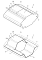
図1及び図2に示す導電部材1は、二つの部材間に介装されることにより、それら二つの部材を電気的に接続する部材で、金属材料で形成された金属部3と、エラストマー材料で形成されたエラストマー部5とを備えている。
Next, an embodiment of the present invention will be described with an example.
The
金属部3は、厚さ0.01mmの金属箔を、図1(b)に示すような形態に加工したもので、大部分がエラストマー部5の内部に埋設され、一部だけがエラストマー部5の外部に露出する状態になっている。
The
より詳しくは、この金属部3は、短冊状の金属箔にスリット状の貫通孔11を一つ形成して、その貫通孔11を挟んで両側にある部分のうち、一方の部分については当該部分を金属箔の表面側へ突出する形態に曲げて凸部13を形成するとともに(図1(b)及び図2(d)参照。)、他方の部分については当該部分を金属箔の裏面側へ突出する形態に曲げて凸部15を形成したものである(図1(b)及び図2(e)参照。)。
More specifically, the
このような加工が金属箔に施されたことにより、貫通孔11は、略六角形の開口をなすように開かれた状態となっている(図1(b)参照。)。なお、以下の説明においては、導電部材1各部の相対的な位置関係を簡潔に説明するため、便宜的に凸部13の突出方向を上、凸部15の突出方向を下として説明を続ける。ただし、ここでいう上下の各方向は、導電部材1の使用状態において、凸部13を上に向けた状態で使用すべきことを意味するものではない。
By performing such processing on the metal foil, the through
凸部13,15は、それぞれの先端部分がエラストマー部5の外部へ露出している。より具体的には、凸部13は、最上端にある金属平面部13Aと、この金属平面部13Aに連設されて下方へと延びる側面部13Bを有する形態とされ、金属平面部13Aと側面部13Bの上端側の一部がエラストマー部5の外部へ露出し、側面部13Bの残りの部分がエラストマー部5の内部に埋設されている。
The
また、凸部15は、最下端にある金属平面部15Aと、この金属平面部15Aに連設されて上方へと延びる側面部15Bを有する形態とされ、金属平面部15Aと側面部15Bの下端側の一部がエラストマー部5の外部へ露出し、側面部15Bの残りの部分がエラストマー部5の内部に埋設されている。なお、金属平面部13Aと金属平面部15Aは、平行な面になっている。
Moreover, the
貫通孔11は、貫通孔11の輪郭線が金属箔の輪郭線に連続しない形態のものであって、輪郭線が金属箔の輪郭線に連続する形態となる切欠き状のものではない。このような形態の貫通孔11を形成することにより、金属箔のうち、凸部13,15とされた部分以外の部分については、平面視した際に一列に並ぶ位置にある凸部13,15の両側において各凸部13,15に連設された一対の連設部17を形成する部分とされている。なお、連設部17の端部は、エラストマー部5の外部に露出する状態にある。
The through
以上のような形態の金属部3は、本実施形態においては、エラストマー部5を成形するために用意された金型内で金属箔を加工することによって形成されている。具体的には、金型内には、あらかじめ貫通孔11が形成された金属箔が配置され、凸部13,15それぞれの突出方向に向かって金型内で治具を突き上げることにより、その治具の先端で凸部13,15となる部分が突出方向へと押し出される。
In the present embodiment, the
そして、このような金属箔の加工を終えたら、引き続いて金型内に、エラストマー部5となる原料組成物を射出することにより、エラストマー部5が成形される。ただし、金属部3をこのような加工方法で加工するか否かは任意であり、他の方法で同等な形状に成形してもよい。
And when the processing of such metal foil is completed, the
一方、エラストマー部5には、金属平面部13A,15Aに対して面一とされたエラストマー平面部21,23が形成されている。また、エラストマー部5において、エラストマー平面部21から連続する部分には、エラストマー部5の端に向かって下り勾配となる傾斜が付与され、これにより、作業者の指先などが引っかかりにくい形態となっている。
On the other hand, the
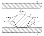
以上のように構成された導電部材1は、例えば、図3に示すように、凸部15がプリント配線板31に対してはんだ付けされるとともに、別のプリント配線板33が凸部13に接触する位置に配置され、これにより、両プリント配線板31,33を電気的に接続することができる。
In the
導電部材1をプリント配線板31上に設置する際には、例えば、自動実装機を使って設置を行うことができ、その際、金属平面部13A及びエラストマー平面部21は、いずれも自動実装機が備える吸引ノズルで導電部材1を吸着するための吸着面として利用することができる。
When installing the
特に、エラストマー平面部21は、エラストマー材料で形成された摩擦係数の高い面になっているので、このエラストマー平面部21を吸着面として利用すれば、吸引ノズルで吸着した導電部材1を移動させる際に、慣性力などを受けて導電部材1の向きが変わってしまうのを抑制することができる。
In particular, since the elastomer
一方、エラストマー平面部23は、導電部材1がプリント配線板31上に配置された際に、滑り止めとして機能する。そのため、例えば、はんだ付けが完了する前の状態で、リフロー炉内での搬送途中にプリント配線板31に振動が伝わるようなことがあっても、そのような振動を受けて導電部材1の向きが変わってしまうのを抑制することができる。
On the other hand, the
また、凸部15をプリント配線板31に対してはんだ付けする際には、はんだフィレット35が形成されることになる部分の高さhを、事前に最適化された高さとすることができる。具体的には、はんだフィレット35が形成されることになる部分の高さhは、エラストマー部5を形成するための金型の設計に応じた所望の高さとされる。
Moreover, when soldering the
この高さhが過剰に小さいと、はんだフィレット35が形成されなくなるため、はんだ付けによる接合強度が低下するものの、この高さhが過剰に大きいと、はんだの濡れ上がり量が増大してはんだフィレット35が大きくなるため、ごく小型の導電部材1である場合には、導電部材1が想定以上にはんだフィレット35に埋没し、導電部材1の柔軟性が損なわれてしまうおそれがある。
If the height h is excessively small, the
この点、この導電部材1であれば、エラストマー部5を設けることで、はんだフィレット35が形成されることになる部分の高さhを、設計通りの位置に制限することができるので、良好な接合強度を確保しつつ、導電部材1の柔軟性も適切に確保することができる。
In this respect, if the
さらに、はんだ付けの完了後、導電部材1がプリント配線板31,33の間に挟み込まれる際には、導電部材1は、プリント配線板31,33間で圧縮されて、その圧縮力を受けて弾性変形する。このとき、導電部材1は、プリント配線板31,33間が狭まる方向へ圧縮されると、図3中に示す矢印P方向へ膨らむように変形する。
Further, when the
金属部3は、図3に示す断面上で、凸部15が下半分の筒状をなす形態となっているものの、上半分は開放された状態にある。そのため、エラストマー部5は、全周にわたって拘束された状態にはなく、図3中に矢印Qで示すように、エラストマー部5の上部においては大きく変形することができる。
In the cross section shown in FIG. 3, the
また、凸部13のある箇所では、上記図3とは上下が逆転し、凸部13が上半分の筒状をなす形態となっているものの、下半分は開放された状態にある。さらに、凸部13のある箇所と凸部15のある箇所の境界では、連設部17しか存在しない状態にある。
Further, at a place where the
つまり、この導電部材1では、凸部13,15の列設方向について、どの位置で断面を見ても、多くても上半分か下半分でエラストマー部5が包囲されている状態にあるだけで、全周にわたってエラストマー部5が包囲されている箇所がない。
In other words, in this
したがって、エラストマー部5が金属部3によって全周にわたって包囲されているようなものとは異なり、エラストマー部5に無理な歪みが生じたり、過剰に圧力がかかったりすることがなく、導電部材1をスムーズに変形させることができる。
Therefore, unlike the case where the
以上、本発明の実施形態について説明したが、本発明は上記の具体的な一実施形態に限定されず、この他にも種々の形態で実施することができる。
例えば、上記実施形態では、上方へ突出する凸部13と、下方へ突出する凸部15を、それぞれ一つずつ設けてある例を示したが、図4(a)及び同図(b)に示す導電部材51のように、上方へ突出する凸部13と、下方へ突出する凸部15を、それぞれ複数設けた金属部53を、エラストマー部55に埋設した構造としてもよい(図4の場合は、五つずつ設けたものを例示。)。
As mentioned above, although embodiment of this invention was described, this invention is not limited to said specific one Embodiment, In addition, it can implement with a various form.
For example, in the above-described embodiment, an example in which the
このような形態にすれば、多点で電気的接触を図ることが可能な多点接点構造を実現することができる。ただし、その分だけ長尺な導電部材となるので、小型化を図るには、図1〜図3に示したものが好ましく、凸部の数をどの程度とするかは、目的に応じて最適な数にすればよい。また、電磁波シールド用ガスケットとして利用する場合など、さらに長尺な導電部材が必要であれば、図4に例示したもの以上に繰り返し単位を増やしてもよい。 With such a configuration, it is possible to realize a multipoint contact structure capable of achieving electrical contact at multiple points. However, since the length of the conductive member becomes that much, the one shown in FIGS. 1 to 3 is preferable in order to reduce the size, and the number of convex portions is optimal depending on the purpose. Any number can be used. In addition, if a longer conductive member is required, such as when used as an electromagnetic shielding gasket, the number of repeating units may be increased beyond that illustrated in FIG.
また、以上説明した事例では、上方へ突出する凸部13と、下方へ突出する凸部15を、同数個に揃えてあったが、例えば、上方へ突出する凸部13が二つで、下方へ突出する凸部15が一つ、といった具合に、凸部13,15の総数が奇数となるような構造になっていてもよい。
Moreover, in the example demonstrated above, although the
このような構造にすれば、吸着面として利用される金属平面部13A又はエラストマー平面部21の位置を、凸部の列設方向両端間の中央にすることができるので、吸引ノズルで吸引したときの安定性を、より一層改善することができる。
With such a structure, the position of the metal
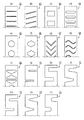
さらに、上記実施形態で示した金属部3や金属部53では、図5(a)に例示する金属箔61のように、短冊状の金属箔の長手方向に対して垂直な方向へ細長く延びる形態とされたスリット状の貫通孔を形成してあったが、貫通孔の形態については、他の形態であってもよい。例えば、図5(b)〜図5(i)に例示する金属箔62〜69のように、様々な形態の貫通孔を考え得る。
Furthermore, in the
また、図5(a)〜図5(i)に例示した貫通孔の代わりに、図5(j)〜図5(o)に例示する金属箔70〜75のように、切欠きが形成されたものを採用してもよい。ただし、短冊状の金属箔が長手方向へ引っ張られた場合には、切欠きを有する金属箔70〜75よりも、貫通孔を有する金属箔61〜69の方が、機械的強度は高くなるので、そのような強度が要求されるか否かも考慮して、貫通孔を設けるか切欠きを設けるかを選定すると好ましい。 Further, instead of the through holes illustrated in FIGS. 5A to 5I, notches are formed as in metal foils 70 to 75 illustrated in FIGS. 5J to 5O. May be used. However, when the strip-shaped metal foil is pulled in the longitudinal direction, the metal foils 61 to 69 having through holes have higher mechanical strength than the metal foils 70 to 75 having notches. It is preferable to select whether to provide a through hole or a notch in consideration of whether such strength is required.
さらに、上述の金属箔61〜75は、いずれも短冊状のものに貫通孔又は切欠きを設けた形態であったが、短冊状(長方形)のものをベースにするか否かも任意である。 Furthermore, although the above-mentioned metal foils 61 to 75 are each in the form of providing a through hole or a notch in a strip shape, whether or not to use a strip shape (rectangular) base is also arbitrary.
1,51・・・導電部材、3・・・金属部、5・・・エラストマー部、11・・・貫通孔、13,15・・・凸部、13A,15A・・・金属平面部、13B,15B・・・側面部、17・・・連設部、21,23・・・エラストマー平面部、31,33・・・プリント配線板、61〜75・・・金属箔。
DESCRIPTION OF
Claims (8)
金属材料からなる面状体に少なくとも一つの貫通孔又は切欠きを形成して、当該貫通孔又は切欠きを挟んで両側にある部分のうち、一方の部分については当該部分を前記面状体の表面側へ突出する形態に曲げるとともに、他方の部分については当該部分を前記面状体の裏面側へ突出する形態に曲げることにより、前記表面側及び前記裏面側の双方それぞれにおいて少なくとも一つの凸部が突出する形態とされた金属部と、
エラストマー材料からなり、前記凸部の先端部分を外部に露出させた状態で前記金属部が埋設されており、前記表面側及び前記裏面側にある凸部のうち、少なくとも一方の側にある凸部の先端部分が前記第一の部材に接するとともに、他方の側にある凸部の先端部分が前記第二の部材に接する向きにされた状態で、前記第一の部材と前記第二の部材との間に挟み込まれた際には、弾性変形することによって、前記凸部の先端部分を前記第一の部材側又は前記第二の部材側に向かって押圧するエラストマー部と
を備えたことを特徴とする導電部材。 A conductive member that electrically connects the first member and the second member by being interposed between the first member and the second member,
Forming at least one through-hole or notch in a planar body made of a metal material, and among the parts on both sides of the through-hole or notch, the part is placed on the planar body. At least one convex portion is formed on each of the front surface side and the back surface side by bending the surface portion to protrude to the front surface side and bending the other portion to a shape protruding to the back surface side of the planar body. A metal part that is shaped to protrude,
The convex portion on the at least one side of the convex portions on the front surface side and the back surface side, which is made of an elastomer material, and the metal portion is embedded with the tip portion of the convex portion exposed to the outside. The first member and the second member in a state in which the tip portion of the projection is in contact with the first member and the tip portion of the convex portion on the other side is in contact with the second member. And an elastomer portion that presses the tip of the convex portion toward the first member or the second member by elastically deforming when sandwiched between them. A conductive member.
ことを特徴とする請求項1に記載の導電部材。 2. The conductive member according to claim 1, wherein the convex portions on the front surface side and the back surface side are formed at positions aligned in a row when viewed from a direction perpendicular to the front and back surfaces of the planar body.
前記面状体のうち、前記凸部とされた部分以外の部分は、前記一列に並ぶ位置にある前記凸部の両側において各凸部に連設された一対の連設部とされている
ことを特徴とする請求項2に記載の導電部材。 The through hole is formed in the planar body,
Of the planar body, the portions other than the portions that are the convex portions are a pair of continuous portions that are connected to the convex portions on both sides of the convex portions that are aligned in a row. The conductive member according to claim 2.
ことを特徴とする請求項3に記載の導電部材。 When sandwiched between the first member and the second member, the pair of connecting portions on both sides of the convex portion are mutually connected with the deformation of the metal portion and the elastomer portion. The conductive member according to claim 3, wherein the conductive member moves in a separating direction.
ことを特徴とする請求項1〜請求項4のいずれか一項に記載の導電部材。 The metal portion is made of a metal foil that plastically deforms in a manner that follows the shape of the elastomer portion when the elastomer portion sandwiched between the first member and the second member is elastically deformed. The conductive member according to any one of claims 1 to 4, wherein the conductive member is characterized in that
ことを特徴とする請求項1〜請求項5のいずれか一項に記載の導電部材。 A metal flat portion formed in a flat shape is provided at a tip portion of the convex portion, and the metal flat portion is parallel between the convex portion on the front surface side and the convex portion on the back surface side. The conductive member according to any one of claims 1 to 5, wherein:
ことを特徴とする請求項6に記載の導電部材。 The conductive member according to claim 6, wherein the elastomer portion is formed with an elastomer plane portion that is flush with the metal plane portion.
当該側面部は、前記金属平面部から連続する一部が前記エラストマー部の外部に露出する一方、残りの部分が前記エラストマー部の内部に埋設されている
ことを特徴とする請求項6又は請求項7に記載の導電部材。 The convex part is configured to have a side part continuously provided at positions on both sides sandwiching the metal flat part,
The said side part is exposed to the exterior of the said elastomer part while the part which continues from the said metal plane part, The remaining part is embed | buried under the inside of the said elastomer part. 8. The conductive member according to 7.
Priority Applications (5)
| Application Number | Priority Date | Filing Date | Title |
|---|---|---|---|
| JP2010253010A JP5799352B2 (en) | 2010-11-11 | 2010-11-11 | Conductive member |
| CN201180054289.XA CN103210544B (en) | 2010-11-11 | 2011-11-11 | Conductive member and production method thereof |
| EP11840431.8A EP2639883A4 (en) | 2010-11-11 | 2011-11-11 | Conductive member and method for producing same |
| US13/882,898 US9196395B2 (en) | 2010-11-11 | 2011-11-11 | Conductive member and method for producing same |
| PCT/JP2011/076098 WO2012063941A1 (en) | 2010-11-11 | 2011-11-11 | Conductive member and method for producing same |
Applications Claiming Priority (1)
| Application Number | Priority Date | Filing Date | Title |
|---|---|---|---|
| JP2010253010A JP5799352B2 (en) | 2010-11-11 | 2010-11-11 | Conductive member |
Publications (2)
| Publication Number | Publication Date |
|---|---|
| JP2012104412A true JP2012104412A (en) | 2012-05-31 |
| JP5799352B2 JP5799352B2 (en) | 2015-10-21 |
Family
ID=46051078
Family Applications (1)
| Application Number | Title | Priority Date | Filing Date |
|---|---|---|---|
| JP2010253010A Active JP5799352B2 (en) | 2010-11-11 | 2010-11-11 | Conductive member |
Country Status (5)
| Country | Link |
|---|---|
| US (1) | US9196395B2 (en) |
| EP (1) | EP2639883A4 (en) |
| JP (1) | JP5799352B2 (en) |
| CN (1) | CN103210544B (en) |
| WO (1) | WO2012063941A1 (en) |
Cited By (1)
| Publication number | Priority date | Publication date | Assignee | Title |
|---|---|---|---|---|
| JP2015002011A (en) * | 2013-06-13 | 2015-01-05 | 富士通株式会社 | Terminal unit and electronic apparatus |
Families Citing this family (1)
| Publication number | Priority date | Publication date | Assignee | Title |
|---|---|---|---|---|
| DE102016213600B4 (en) * | 2016-07-25 | 2019-03-14 | Audi Ag | Sealing element for fluid-tight and electrically conductive connection of a first component and a second component and corresponding component arrangement |
Citations (4)
| Publication number | Priority date | Publication date | Assignee | Title |
|---|---|---|---|---|
| JPS5741268U (en) * | 1980-08-21 | 1982-03-05 | ||
| JPH08293340A (en) * | 1995-04-14 | 1996-11-05 | Whitaker Corp:The | Elastomer connector |
| JPH09115574A (en) * | 1995-10-13 | 1997-05-02 | Smk Corp | Connection terminal |
| JP2003031984A (en) * | 2001-07-18 | 2003-01-31 | Seiwa Electric Mfg Co Ltd | Gasket for electromagnetic shield |
Family Cites Families (15)
| Publication number | Priority date | Publication date | Assignee | Title |
|---|---|---|---|---|
| US3530033A (en) * | 1967-01-26 | 1970-09-22 | Baldwin Lima Hamilton Corp | Elongated strip of elastomeric material with spaced metal strips embedded therein |
| JPS568081U (en) * | 1979-06-29 | 1981-01-23 | ||
| JPS5741268A (en) | 1980-08-20 | 1982-03-08 | Honda Motor Co Ltd | Circuit for detecting steering angle center of vehicle |
| US4839227A (en) * | 1987-03-12 | 1989-06-13 | Minnesota Mining And Manufacturing Company | Resilient electrically and thermally conductive flexible composite |
| US4864076A (en) | 1988-10-24 | 1989-09-05 | Instrument Specialties Co., Inc. | Electromagnetic shielding and environmental sealing device |
| JP3461586B2 (en) | 1994-09-27 | 2003-10-27 | 北川工業株式会社 | Electromagnetic wave shielding material |
| US6146151A (en) * | 1999-08-18 | 2000-11-14 | Hon Hai Precision Ind. Co., Ltd. | Method for forming an electrical connector and an electrical connector obtained by the method |
| JP2002075567A (en) * | 2000-08-25 | 2002-03-15 | Shin Etsu Polymer Co Ltd | Electric connector and its manufacturing method |
| US6456504B1 (en) * | 2000-10-31 | 2002-09-24 | 3Com Corporation | Surface mounted grounding clip for shielded enclosures |
| JP3978174B2 (en) * | 2003-03-07 | 2007-09-19 | 北川工業株式会社 | contact |
| USD525207S1 (en) * | 2003-12-02 | 2006-07-18 | Antares Contech, Inc. | Sheet metal interconnect array |
| US7112740B2 (en) | 2005-02-11 | 2006-09-26 | Laird Technologies, Inc. | Shielding strips |
| DE102005033593B3 (en) * | 2005-07-19 | 2007-01-04 | Hirschmann Car Communication Gmbh | Contact spring in a support frame of an antenna amplifier of a vehicle |
| JP4739169B2 (en) * | 2006-11-13 | 2011-08-03 | 北川工業株式会社 | Elastic contact |
| US7527506B2 (en) * | 2007-08-31 | 2009-05-05 | Laird Technologies, Inc. | EMI shielding/electrical grounding members |
-
2010
- 2010-11-11 JP JP2010253010A patent/JP5799352B2/en active Active
-
2011
- 2011-11-11 CN CN201180054289.XA patent/CN103210544B/en not_active Expired - Fee Related
- 2011-11-11 WO PCT/JP2011/076098 patent/WO2012063941A1/en active Application Filing
- 2011-11-11 EP EP11840431.8A patent/EP2639883A4/en not_active Withdrawn
- 2011-11-11 US US13/882,898 patent/US9196395B2/en not_active Expired - Fee Related
Patent Citations (4)
| Publication number | Priority date | Publication date | Assignee | Title |
|---|---|---|---|---|
| JPS5741268U (en) * | 1980-08-21 | 1982-03-05 | ||
| JPH08293340A (en) * | 1995-04-14 | 1996-11-05 | Whitaker Corp:The | Elastomer connector |
| JPH09115574A (en) * | 1995-10-13 | 1997-05-02 | Smk Corp | Connection terminal |
| JP2003031984A (en) * | 2001-07-18 | 2003-01-31 | Seiwa Electric Mfg Co Ltd | Gasket for electromagnetic shield |
Cited By (1)
| Publication number | Priority date | Publication date | Assignee | Title |
|---|---|---|---|---|
| JP2015002011A (en) * | 2013-06-13 | 2015-01-05 | 富士通株式会社 | Terminal unit and electronic apparatus |
Also Published As
| Publication number | Publication date |
|---|---|
| US9196395B2 (en) | 2015-11-24 |
| EP2639883A1 (en) | 2013-09-18 |
| US20130220678A1 (en) | 2013-08-29 |
| JP5799352B2 (en) | 2015-10-21 |
| WO2012063941A1 (en) | 2012-05-18 |
| CN103210544A (en) | 2013-07-17 |
| EP2639883A4 (en) | 2017-03-15 |
| CN103210544B (en) | 2015-12-16 |
Similar Documents
| Publication | Publication Date | Title |
|---|---|---|
| CN102458091B (en) | Electromagnetic interference shielding gasket | |
| EP2041842B1 (en) | Solderable electric contact terminal | |
| JP2006310599A (en) | Clamp | |
| CN105531874A (en) | Clamping spring | |
| JP3978174B2 (en) | contact | |
| JP5799352B2 (en) | Conductive member | |
| US9673551B2 (en) | Electrical connector with one-piece terminals | |
| CN101454947B (en) | Contact terminal for sockets and semiconductor device | |
| KR101033193B1 (en) | Emi shielding gasket | |
| CN208674449U (en) | Anti- routed terminal, deck and mobile device | |
| KR101600510B1 (en) | Pocket-typed electric contact terminal capable for surface mounting with reflow soldering process | |
| JPWO2003079494A1 (en) | Anisotropic conductive sheet and manufacturing method thereof | |
| KR20100041975A (en) | Elastic conductive contact terminal for surface mount | |
| KR20190088842A (en) | Elastic electric contact terminal | |
| KR101663826B1 (en) | Elastic signal pin | |
| KR100667260B1 (en) | Structure for fixing wire of terminal clamping machine tool | |
| CN106099484B (en) | Welding section be extended with only epipodium around the surface-mounted elastic sheet of side wall | |
| JP4603424B2 (en) | Shock absorbing spacer | |
| KR102651162B1 (en) | Elastic and electric contact terminal and Structure for mounting the same | |
| KR101260204B1 (en) | Contactor | |
| KR102212350B1 (en) | Electric contact terminal capable for surface mounting with low compressive force | |
| KR200463675Y1 (en) | A connector | |
| CN103378423B (en) | Clamping type wire connector | |
| CN209747383U (en) | Electronic equipment on-off controller | |
| CN215070546U (en) | Elastic sheet connector |
Legal Events
| Date | Code | Title | Description |
|---|---|---|---|
| A621 | Written request for application examination |
Free format text: JAPANESE INTERMEDIATE CODE: A621 Effective date: 20131107 |
|
| A131 | Notification of reasons for refusal |
Free format text: JAPANESE INTERMEDIATE CODE: A131 Effective date: 20140909 |
|
| A02 | Decision of refusal |
Free format text: JAPANESE INTERMEDIATE CODE: A02 Effective date: 20150210 |
|
| A521 | Request for written amendment filed |
Free format text: JAPANESE INTERMEDIATE CODE: A523 Effective date: 20150511 |
|
| A911 | Transfer to examiner for re-examination before appeal (zenchi) |
Free format text: JAPANESE INTERMEDIATE CODE: A911 Effective date: 20150519 |
|
| TRDD | Decision of grant or rejection written | ||
| A01 | Written decision to grant a patent or to grant a registration (utility model) |
Free format text: JAPANESE INTERMEDIATE CODE: A01 Effective date: 20150623 |
|
| A61 | First payment of annual fees (during grant procedure) |
Free format text: JAPANESE INTERMEDIATE CODE: A61 Effective date: 20150722 |
|
| R150 | Certificate of patent or registration of utility model |
Ref document number: 5799352 Country of ref document: JP Free format text: JAPANESE INTERMEDIATE CODE: R150 |
|
| R250 | Receipt of annual fees |
Free format text: JAPANESE INTERMEDIATE CODE: R250 |
|
| R250 | Receipt of annual fees |
Free format text: JAPANESE INTERMEDIATE CODE: R250 |
|
| R250 | Receipt of annual fees |
Free format text: JAPANESE INTERMEDIATE CODE: R250 |
|
| R250 | Receipt of annual fees |
Free format text: JAPANESE INTERMEDIATE CODE: R250 |
|
| R250 | Receipt of annual fees |
Free format text: JAPANESE INTERMEDIATE CODE: R250 |
|
| R250 | Receipt of annual fees |
Free format text: JAPANESE INTERMEDIATE CODE: R250 |