WO2012057323A1 - 組電池及びこれを備える車両 - Google Patents
組電池及びこれを備える車両 Download PDFInfo
- Publication number
- WO2012057323A1 WO2012057323A1 PCT/JP2011/074946 JP2011074946W WO2012057323A1 WO 2012057323 A1 WO2012057323 A1 WO 2012057323A1 JP 2011074946 W JP2011074946 W JP 2011074946W WO 2012057323 A1 WO2012057323 A1 WO 2012057323A1
- Authority
- WO
- WIPO (PCT)
- Prior art keywords
- battery
- harness
- cover
- wire harness
- electrode terminal
- Prior art date
- Legal status (The legal status is an assumption and is not a legal conclusion. Google has not performed a legal analysis and makes no representation as to the accuracy of the status listed.)
- Ceased
Links
Images



Classifications
-
- B—PERFORMING OPERATIONS; TRANSPORTING
- B60—VEHICLES IN GENERAL
- B60L—PROPULSION OF ELECTRICALLY-PROPELLED VEHICLES; SUPPLYING ELECTRIC POWER FOR AUXILIARY EQUIPMENT OF ELECTRICALLY-PROPELLED VEHICLES; ELECTRODYNAMIC BRAKE SYSTEMS FOR VEHICLES IN GENERAL; MAGNETIC SUSPENSION OR LEVITATION FOR VEHICLES; MONITORING OPERATING VARIABLES OF ELECTRICALLY-PROPELLED VEHICLES; ELECTRIC SAFETY DEVICES FOR ELECTRICALLY-PROPELLED VEHICLES
- B60L50/00—Electric propulsion with power supplied within the vehicle
- B60L50/50—Electric propulsion with power supplied within the vehicle using propulsion power supplied by batteries or fuel cells
- B60L50/60—Electric propulsion with power supplied within the vehicle using propulsion power supplied by batteries or fuel cells using power supplied by batteries
- B60L50/64—Constructional details of batteries specially adapted for electric vehicles
-
- B—PERFORMING OPERATIONS; TRANSPORTING
- B60—VEHICLES IN GENERAL
- B60L—PROPULSION OF ELECTRICALLY-PROPELLED VEHICLES; SUPPLYING ELECTRIC POWER FOR AUXILIARY EQUIPMENT OF ELECTRICALLY-PROPELLED VEHICLES; ELECTRODYNAMIC BRAKE SYSTEMS FOR VEHICLES IN GENERAL; MAGNETIC SUSPENSION OR LEVITATION FOR VEHICLES; MONITORING OPERATING VARIABLES OF ELECTRICALLY-PROPELLED VEHICLES; ELECTRIC SAFETY DEVICES FOR ELECTRICALLY-PROPELLED VEHICLES
- B60L1/00—Supplying electric power to auxiliary equipment of vehicles
- B60L1/003—Supplying electric power to auxiliary equipment of vehicles to auxiliary motors, e.g. for pumps, compressors
-
- B—PERFORMING OPERATIONS; TRANSPORTING
- B60—VEHICLES IN GENERAL
- B60L—PROPULSION OF ELECTRICALLY-PROPELLED VEHICLES; SUPPLYING ELECTRIC POWER FOR AUXILIARY EQUIPMENT OF ELECTRICALLY-PROPELLED VEHICLES; ELECTRODYNAMIC BRAKE SYSTEMS FOR VEHICLES IN GENERAL; MAGNETIC SUSPENSION OR LEVITATION FOR VEHICLES; MONITORING OPERATING VARIABLES OF ELECTRICALLY-PROPELLED VEHICLES; ELECTRIC SAFETY DEVICES FOR ELECTRICALLY-PROPELLED VEHICLES
- B60L50/00—Electric propulsion with power supplied within the vehicle
- B60L50/10—Electric propulsion with power supplied within the vehicle using propulsion power supplied by engine-driven generators, e.g. generators driven by combustion engines
- B60L50/16—Electric propulsion with power supplied within the vehicle using propulsion power supplied by engine-driven generators, e.g. generators driven by combustion engines with provision for separate direct mechanical propulsion
-
- B—PERFORMING OPERATIONS; TRANSPORTING
- B60—VEHICLES IN GENERAL
- B60L—PROPULSION OF ELECTRICALLY-PROPELLED VEHICLES; SUPPLYING ELECTRIC POWER FOR AUXILIARY EQUIPMENT OF ELECTRICALLY-PROPELLED VEHICLES; ELECTRODYNAMIC BRAKE SYSTEMS FOR VEHICLES IN GENERAL; MAGNETIC SUSPENSION OR LEVITATION FOR VEHICLES; MONITORING OPERATING VARIABLES OF ELECTRICALLY-PROPELLED VEHICLES; ELECTRIC SAFETY DEVICES FOR ELECTRICALLY-PROPELLED VEHICLES
- B60L50/00—Electric propulsion with power supplied within the vehicle
- B60L50/50—Electric propulsion with power supplied within the vehicle using propulsion power supplied by batteries or fuel cells
- B60L50/60—Electric propulsion with power supplied within the vehicle using propulsion power supplied by batteries or fuel cells using power supplied by batteries
- B60L50/66—Arrangements of batteries
-
- B—PERFORMING OPERATIONS; TRANSPORTING
- B60—VEHICLES IN GENERAL
- B60L—PROPULSION OF ELECTRICALLY-PROPELLED VEHICLES; SUPPLYING ELECTRIC POWER FOR AUXILIARY EQUIPMENT OF ELECTRICALLY-PROPELLED VEHICLES; ELECTRODYNAMIC BRAKE SYSTEMS FOR VEHICLES IN GENERAL; MAGNETIC SUSPENSION OR LEVITATION FOR VEHICLES; MONITORING OPERATING VARIABLES OF ELECTRICALLY-PROPELLED VEHICLES; ELECTRIC SAFETY DEVICES FOR ELECTRICALLY-PROPELLED VEHICLES
- B60L58/00—Methods or circuit arrangements for monitoring or controlling batteries or fuel cells, specially adapted for electric vehicles
- B60L58/10—Methods or circuit arrangements for monitoring or controlling batteries or fuel cells, specially adapted for electric vehicles for monitoring or controlling batteries
- B60L58/18—Methods or circuit arrangements for monitoring or controlling batteries or fuel cells, specially adapted for electric vehicles for monitoring or controlling batteries of two or more battery modules
- B60L58/21—Methods or circuit arrangements for monitoring or controlling batteries or fuel cells, specially adapted for electric vehicles for monitoring or controlling batteries of two or more battery modules having the same nominal voltage
-
- B—PERFORMING OPERATIONS; TRANSPORTING
- B60—VEHICLES IN GENERAL
- B60L—PROPULSION OF ELECTRICALLY-PROPELLED VEHICLES; SUPPLYING ELECTRIC POWER FOR AUXILIARY EQUIPMENT OF ELECTRICALLY-PROPELLED VEHICLES; ELECTRODYNAMIC BRAKE SYSTEMS FOR VEHICLES IN GENERAL; MAGNETIC SUSPENSION OR LEVITATION FOR VEHICLES; MONITORING OPERATING VARIABLES OF ELECTRICALLY-PROPELLED VEHICLES; ELECTRIC SAFETY DEVICES FOR ELECTRICALLY-PROPELLED VEHICLES
- B60L58/00—Methods or circuit arrangements for monitoring or controlling batteries or fuel cells, specially adapted for electric vehicles
- B60L58/10—Methods or circuit arrangements for monitoring or controlling batteries or fuel cells, specially adapted for electric vehicles for monitoring or controlling batteries
- B60L58/24—Methods or circuit arrangements for monitoring or controlling batteries or fuel cells, specially adapted for electric vehicles for monitoring or controlling batteries for controlling the temperature of batteries
- B60L58/26—Methods or circuit arrangements for monitoring or controlling batteries or fuel cells, specially adapted for electric vehicles for monitoring or controlling batteries for controlling the temperature of batteries by cooling
-
- B—PERFORMING OPERATIONS; TRANSPORTING
- B60—VEHICLES IN GENERAL
- B60L—PROPULSION OF ELECTRICALLY-PROPELLED VEHICLES; SUPPLYING ELECTRIC POWER FOR AUXILIARY EQUIPMENT OF ELECTRICALLY-PROPELLED VEHICLES; ELECTRODYNAMIC BRAKE SYSTEMS FOR VEHICLES IN GENERAL; MAGNETIC SUSPENSION OR LEVITATION FOR VEHICLES; MONITORING OPERATING VARIABLES OF ELECTRICALLY-PROPELLED VEHICLES; ELECTRIC SAFETY DEVICES FOR ELECTRICALLY-PROPELLED VEHICLES
- B60L7/00—Electrodynamic brake systems for vehicles in general
- B60L7/10—Dynamic electric regenerative braking
- B60L7/14—Dynamic electric regenerative braking for vehicles propelled by AC motors
-
- H—ELECTRICITY
- H01—ELECTRIC ELEMENTS
- H01M—PROCESSES OR MEANS, e.g. BATTERIES, FOR THE DIRECT CONVERSION OF CHEMICAL ENERGY INTO ELECTRICAL ENERGY
- H01M10/00—Secondary cells; Manufacture thereof
- H01M10/42—Methods or arrangements for servicing or maintenance of secondary cells or secondary half-cells
- H01M10/48—Accumulators combined with arrangements for measuring, testing or indicating the condition of cells, e.g. the level or density of the electrolyte
- H01M10/482—Accumulators combined with arrangements for measuring, testing or indicating the condition of cells, e.g. the level or density of the electrolyte for several batteries or cells simultaneously or sequentially
-
- H—ELECTRICITY
- H01—ELECTRIC ELEMENTS
- H01M—PROCESSES OR MEANS, e.g. BATTERIES, FOR THE DIRECT CONVERSION OF CHEMICAL ENERGY INTO ELECTRICAL ENERGY
- H01M50/00—Constructional details or processes of manufacture of the non-active parts of electrochemical cells other than fuel cells, e.g. hybrid cells
- H01M50/50—Current conducting connections for cells or batteries
- H01M50/572—Means for preventing undesired use or discharge
- H01M50/584—Means for preventing undesired use or discharge for preventing incorrect connections inside or outside the batteries
- H01M50/588—Means for preventing undesired use or discharge for preventing incorrect connections inside or outside the batteries outside the batteries, e.g. incorrect connections of terminals or busbars
-
- H—ELECTRICITY
- H01—ELECTRIC ELEMENTS
- H01M—PROCESSES OR MEANS, e.g. BATTERIES, FOR THE DIRECT CONVERSION OF CHEMICAL ENERGY INTO ELECTRICAL ENERGY
- H01M50/00—Constructional details or processes of manufacture of the non-active parts of electrochemical cells other than fuel cells, e.g. hybrid cells
- H01M50/50—Current conducting connections for cells or batteries
- H01M50/572—Means for preventing undesired use or discharge
- H01M50/584—Means for preventing undesired use or discharge for preventing incorrect connections inside or outside the batteries
- H01M50/59—Means for preventing undesired use or discharge for preventing incorrect connections inside or outside the batteries characterised by the protection means
- H01M50/593—Spacers; Insulating plates
-
- B—PERFORMING OPERATIONS; TRANSPORTING
- B60—VEHICLES IN GENERAL
- B60L—PROPULSION OF ELECTRICALLY-PROPELLED VEHICLES; SUPPLYING ELECTRIC POWER FOR AUXILIARY EQUIPMENT OF ELECTRICALLY-PROPELLED VEHICLES; ELECTRODYNAMIC BRAKE SYSTEMS FOR VEHICLES IN GENERAL; MAGNETIC SUSPENSION OR LEVITATION FOR VEHICLES; MONITORING OPERATING VARIABLES OF ELECTRICALLY-PROPELLED VEHICLES; ELECTRIC SAFETY DEVICES FOR ELECTRICALLY-PROPELLED VEHICLES
- B60L2210/00—Converter types
- B60L2210/30—AC to DC converters
-
- B—PERFORMING OPERATIONS; TRANSPORTING
- B60—VEHICLES IN GENERAL
- B60L—PROPULSION OF ELECTRICALLY-PROPELLED VEHICLES; SUPPLYING ELECTRIC POWER FOR AUXILIARY EQUIPMENT OF ELECTRICALLY-PROPELLED VEHICLES; ELECTRODYNAMIC BRAKE SYSTEMS FOR VEHICLES IN GENERAL; MAGNETIC SUSPENSION OR LEVITATION FOR VEHICLES; MONITORING OPERATING VARIABLES OF ELECTRICALLY-PROPELLED VEHICLES; ELECTRIC SAFETY DEVICES FOR ELECTRICALLY-PROPELLED VEHICLES
- B60L2210/00—Converter types
- B60L2210/40—DC to AC converters
-
- B—PERFORMING OPERATIONS; TRANSPORTING
- B60—VEHICLES IN GENERAL
- B60L—PROPULSION OF ELECTRICALLY-PROPELLED VEHICLES; SUPPLYING ELECTRIC POWER FOR AUXILIARY EQUIPMENT OF ELECTRICALLY-PROPELLED VEHICLES; ELECTRODYNAMIC BRAKE SYSTEMS FOR VEHICLES IN GENERAL; MAGNETIC SUSPENSION OR LEVITATION FOR VEHICLES; MONITORING OPERATING VARIABLES OF ELECTRICALLY-PROPELLED VEHICLES; ELECTRIC SAFETY DEVICES FOR ELECTRICALLY-PROPELLED VEHICLES
- B60L2240/00—Control parameters of input or output; Target parameters
- B60L2240/40—Drive Train control parameters
- B60L2240/54—Drive Train control parameters related to batteries
- B60L2240/545—Temperature
-
- B—PERFORMING OPERATIONS; TRANSPORTING
- B60—VEHICLES IN GENERAL
- B60L—PROPULSION OF ELECTRICALLY-PROPELLED VEHICLES; SUPPLYING ELECTRIC POWER FOR AUXILIARY EQUIPMENT OF ELECTRICALLY-PROPELLED VEHICLES; ELECTRODYNAMIC BRAKE SYSTEMS FOR VEHICLES IN GENERAL; MAGNETIC SUSPENSION OR LEVITATION FOR VEHICLES; MONITORING OPERATING VARIABLES OF ELECTRICALLY-PROPELLED VEHICLES; ELECTRIC SAFETY DEVICES FOR ELECTRICALLY-PROPELLED VEHICLES
- B60L2270/00—Problem solutions or means not otherwise provided for
- B60L2270/10—Emission reduction
- B60L2270/14—Emission reduction of noise
- B60L2270/145—Structure borne vibrations
-
- H—ELECTRICITY
- H01—ELECTRIC ELEMENTS
- H01M—PROCESSES OR MEANS, e.g. BATTERIES, FOR THE DIRECT CONVERSION OF CHEMICAL ENERGY INTO ELECTRICAL ENERGY
- H01M2220/00—Batteries for particular applications
- H01M2220/20—Batteries in motive systems, e.g. vehicle, ship, plane
-
- H—ELECTRICITY
- H01—ELECTRIC ELEMENTS
- H01M—PROCESSES OR MEANS, e.g. BATTERIES, FOR THE DIRECT CONVERSION OF CHEMICAL ENERGY INTO ELECTRICAL ENERGY
- H01M50/00—Constructional details or processes of manufacture of the non-active parts of electrochemical cells other than fuel cells, e.g. hybrid cells
- H01M50/50—Current conducting connections for cells or batteries
- H01M50/502—Interconnectors for connecting terminals of adjacent batteries; Interconnectors for connecting cells outside a battery casing
- H01M50/503—Interconnectors for connecting terminals of adjacent batteries; Interconnectors for connecting cells outside a battery casing characterised by the shape of the interconnectors
-
- H—ELECTRICITY
- H01—ELECTRIC ELEMENTS
- H01M—PROCESSES OR MEANS, e.g. BATTERIES, FOR THE DIRECT CONVERSION OF CHEMICAL ENERGY INTO ELECTRICAL ENERGY
- H01M50/00—Constructional details or processes of manufacture of the non-active parts of electrochemical cells other than fuel cells, e.g. hybrid cells
- H01M50/50—Current conducting connections for cells or batteries
- H01M50/502—Interconnectors for connecting terminals of adjacent batteries; Interconnectors for connecting cells outside a battery casing
- H01M50/514—Methods for interconnecting adjacent batteries or cells
- H01M50/517—Methods for interconnecting adjacent batteries or cells by fixing means, e.g. screws, rivets or bolts
-
- H—ELECTRICITY
- H01—ELECTRIC ELEMENTS
- H01M—PROCESSES OR MEANS, e.g. BATTERIES, FOR THE DIRECT CONVERSION OF CHEMICAL ENERGY INTO ELECTRICAL ENERGY
- H01M50/00—Constructional details or processes of manufacture of the non-active parts of electrochemical cells other than fuel cells, e.g. hybrid cells
- H01M50/50—Current conducting connections for cells or batteries
- H01M50/502—Interconnectors for connecting terminals of adjacent batteries; Interconnectors for connecting cells outside a battery casing
- H01M50/521—Interconnectors for connecting terminals of adjacent batteries; Interconnectors for connecting cells outside a battery casing characterised by the material
- H01M50/522—Inorganic material
-
- Y—GENERAL TAGGING OF NEW TECHNOLOGICAL DEVELOPMENTS; GENERAL TAGGING OF CROSS-SECTIONAL TECHNOLOGIES SPANNING OVER SEVERAL SECTIONS OF THE IPC; TECHNICAL SUBJECTS COVERED BY FORMER USPC CROSS-REFERENCE ART COLLECTIONS [XRACs] AND DIGESTS
- Y02—TECHNOLOGIES OR APPLICATIONS FOR MITIGATION OR ADAPTATION AGAINST CLIMATE CHANGE
- Y02E—REDUCTION OF GREENHOUSE GAS [GHG] EMISSIONS, RELATED TO ENERGY GENERATION, TRANSMISSION OR DISTRIBUTION
- Y02E60/00—Enabling technologies; Technologies with a potential or indirect contribution to GHG emissions mitigation
- Y02E60/10—Energy storage using batteries
-
- Y—GENERAL TAGGING OF NEW TECHNOLOGICAL DEVELOPMENTS; GENERAL TAGGING OF CROSS-SECTIONAL TECHNOLOGIES SPANNING OVER SEVERAL SECTIONS OF THE IPC; TECHNICAL SUBJECTS COVERED BY FORMER USPC CROSS-REFERENCE ART COLLECTIONS [XRACs] AND DIGESTS
- Y02—TECHNOLOGIES OR APPLICATIONS FOR MITIGATION OR ADAPTATION AGAINST CLIMATE CHANGE
- Y02T—CLIMATE CHANGE MITIGATION TECHNOLOGIES RELATED TO TRANSPORTATION
- Y02T10/00—Road transport of goods or passengers
- Y02T10/60—Other road transportation technologies with climate change mitigation effect
- Y02T10/70—Energy storage systems for electromobility, e.g. batteries
-
- Y—GENERAL TAGGING OF NEW TECHNOLOGICAL DEVELOPMENTS; GENERAL TAGGING OF CROSS-SECTIONAL TECHNOLOGIES SPANNING OVER SEVERAL SECTIONS OF THE IPC; TECHNICAL SUBJECTS COVERED BY FORMER USPC CROSS-REFERENCE ART COLLECTIONS [XRACs] AND DIGESTS
- Y02—TECHNOLOGIES OR APPLICATIONS FOR MITIGATION OR ADAPTATION AGAINST CLIMATE CHANGE
- Y02T—CLIMATE CHANGE MITIGATION TECHNOLOGIES RELATED TO TRANSPORTATION
- Y02T10/00—Road transport of goods or passengers
- Y02T10/60—Other road transportation technologies with climate change mitigation effect
- Y02T10/7072—Electromobility specific charging systems or methods for batteries, ultracapacitors, supercapacitors or double-layer capacitors
-
- Y—GENERAL TAGGING OF NEW TECHNOLOGICAL DEVELOPMENTS; GENERAL TAGGING OF CROSS-SECTIONAL TECHNOLOGIES SPANNING OVER SEVERAL SECTIONS OF THE IPC; TECHNICAL SUBJECTS COVERED BY FORMER USPC CROSS-REFERENCE ART COLLECTIONS [XRACs] AND DIGESTS
- Y02—TECHNOLOGIES OR APPLICATIONS FOR MITIGATION OR ADAPTATION AGAINST CLIMATE CHANGE
- Y02T—CLIMATE CHANGE MITIGATION TECHNOLOGIES RELATED TO TRANSPORTATION
- Y02T10/00—Road transport of goods or passengers
- Y02T10/60—Other road transportation technologies with climate change mitigation effect
- Y02T10/72—Electric energy management in electromobility
Definitions
- the present invention relates to an assembled battery mainly used for a power source of a motor for driving a vehicle such as a hybrid vehicle and an electric vehicle, and a vehicle including the same.
- An automobile such as an electric automobile traveling with a motor or a hybrid automobile traveling with both a motor and an engine is equipped with a power supply device in which battery cells are housed in an outer case.
- a large number of battery cells are connected in series to increase the output voltage in order to obtain an output for causing a motor vehicle to travel by a motor.
- a battery cell is formed by stacking battery cells each having a rectangular outer can, and a plurality of the battery packs are connected to form a power supply device (see, for example, Patent Documents 1 and 2).
- Each battery cell has positive and negative electrode terminals projected on the top surface. Each electrode terminal is insulated and fixed to the sealing plate.
- a plurality of battery cells are stacked with insulating separators interposed therebetween, and fixed by being sandwiched by end plates at both ends. The end plate is fastened by a metal bind bar to fix the battery cells in a stacked state.
- Battery cells adjacent to each other are electrically connected by bus bars screwed or laser welded to the respective electrode terminals.
- the battery pack detects the charge / discharge state of each battery cell, and detects the voltage of each battery cell in order to prevent overcharge or overdischarge.
- the battery pack In order to detect the cell voltage of each battery cell, the battery pack connects a wire harness to the electrode terminal, and connects each battery cell to the voltage detection circuit with the wire harness. Moreover, the battery pack covers the upper surface with a terminal cover in order to prevent the short circuit of an adjacent electrode terminal and to protect this.
- the conventional terminal cover only covers the electrode terminal, the wire harness is not fixed inside the terminal cover, and it is in a state of free movement. For this reason, particularly in the on-vehicle application, the wire harness comes in contact with the electrode terminal due to vibration or impact, and the insulation coating is damaged due to friction or rubbing, and in the worst case, the electrode terminal may be shorted. Furthermore, when fixing a terminal cover, there also existed a possibility of pinching and damaging a wire harness between a terminal cover and an assembled battery upper surface.
- This invention is made in view of such a background, The main objective is to provide the assembled battery which avoided the contact of a wire harness and an electrode terminal, and improved reliability, and a vehicle provided with this. It is in.
- a plurality of battery cells 1 having the electrode terminals 3 on the upper surface, and a plurality of adjacent battery cells 1 in a stacked state A bus bar 6 connecting the electrode terminals 3 of the cell 1 and a wire harness 7 connected to the electrode terminals 3 are provided, and further, an insulating separation wall 11 between the electrode terminals 3 and the wire harness 7; 51, 71 are provided.
- the wire harness does not directly touch the electrode terminal, and the coating of the wire harness is damaged by the electrode terminal, which is an electrode There is a feature that the reliability of the assembled battery can be improved without shorting the terminals.
- the harness accommodating part 12 which accommodates the said wire harness 7 can be provided. Accordingly, by storing the wire harness in the harness storage portion, movement and runaway of the wire harness due to vibration or the like can be restricted, and wear due to rubbing can be further reduced.
- the harness storage portion 12 can be provided with the opening window 15.
- the state of the wire harness stored in the harness storage portion can be visually observed from the outside through the opening window, so that it can be confirmed that biting of the wire harness does not occur at the time of installation, etc. Can contribute to the improvement of reliability.
- the insulating separation wall 11 can be formed to be curved along the electrode terminal 3.
- the wire harness is also arranged to be curved, and an advantage is obtained that the variation or the like of the wire harness with different lengths can be absorbed by the curved surface.
- the harness cover 10 can be configured by integrally molding the insulating separation wall 11 and the harness storage portion 12.
- the harness cover by mounting the harness cover on the upper surface of the battery assembly, the insulating separation wall and the harness storage portion can be formed, and the configuration can be simplified, which is advantageous in terms of assembly and cost.
- the insulating separating wall 11 is formed continuously with the edge of the opening window 15, and the insulating separating wall 11 is formed of the battery cell 1. It can be provided inclined with respect to the upper surface.
- the state of the wire harness stored in the harness storage portion can be easily viewed through the opening window.
- the wire harness can be easily guided so as not to be caught by the insulating separation wall.
- the insulating separation wall 11 can be formed to be curved in a plan view at the end edge of the harness storage portion 12.
- the wire harness can be curved at the end edge of the harness storage portion and can be guided to the outside of the harness storage portion.
- the harness cover 10 can be coupled to the separator by providing a plurality of insulating separators interposed between the plurality of battery cells. .
- the harness cover can be easily connected to the fixed position.
- the above-mentioned battery assembly can be provided.
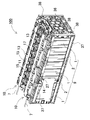
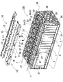
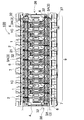
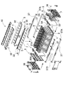
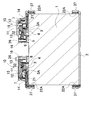
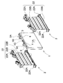
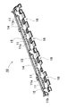
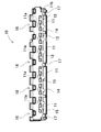
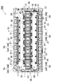
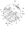
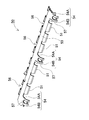
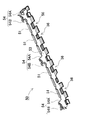
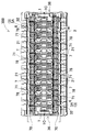
- FIG. 1 It is a perspective view of the assembled battery concerning one example of the present invention. It is the disassembled perspective view which removed the harness cover of the assembled battery shown in FIG. It is a top view of the assembled battery shown in FIG. It is a disassembled perspective view of the assembled battery shown in FIG. It is a vertical cross-sectional view of the assembled battery shown in FIG. It is a disassembled perspective view which shows the laminated structure of a battery cell and a separator. It is a perspective view of the harness cover of the assembled battery shown in FIG. It is a bottom perspective view of the harness cover shown in FIG. It is a bottom view of the harness cover shown in FIG. It is a top view of the assembled battery concerning the other Example of this invention.
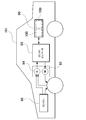
- FIG. 1 is a block diagram showing a hybrid car according to an embodiment of the present invention, which is driven by an engine and a motor. It is a vehicle concerning another example of the present invention, and is a block diagram showing an electric car which runs only with a motor.
- each element constituting the present invention may be configured such that a plurality of elements are constituted by the same member and one member is used in common as a plurality of elements, or conversely, the function of one member is realized by a plurality of members It can be shared and realized.
- the battery pack of the present invention is mainly used as a power supply device for a vehicle, and is used as a power supply for supplying electric power to a hybrid car traveling with both an engine and a motor and a traveling motor of an electric vehicle such as an electric car traveling only with a motor. It is optimal. It can also be used in vehicles other than hybrid cars and electric cars.
- the assembled battery 100 shown in FIGS. 1 to 5 constitutes a battery block 9 by arranging a plurality of battery cells 1 in a mutually insulated state in a stacked state.
- the battery cell 1 is a thin prismatic battery thinner than the width, and is laminated with the separator 2 interposed therebetween in a posture parallel to each other, insulated by the separator 2. As shown in FIG. 5 and FIG. 6, the battery cell 1 is fixed by projecting positive and negative electrode terminals 3 at both ends of the upper surface. The position where the electrode terminal 3 is projected is a position where the positive electrode and the negative electrode are symmetrical in the left-right direction. Thus, the battery cell 1 is turned upside down so that the left and right sides are reversed, stacked one on another, and the adjacent positive and negative electrode terminals 3 of the negative electrode are connected by the bus bar 6 of the metal plate or directly connected. , Can be connected in series.
- the battery pack 1 in which the battery cells 1 are connected in series can increase the output voltage to increase the output. However, the battery pack can also connect battery cells in parallel and in series.
- the battery cell 1 is a lithium ion secondary battery.
- the prismatic battery is not specified as a lithium ion secondary battery, and all rechargeable batteries, for example, a nickel hydrogen battery can be used.
- an electrode assembly in which positive and negative electrode plates are stacked is housed in an outer can 1A, filled with an electrolytic solution, and hermetically sealed.
- the outer can 1A is formed into a square tubular shape that closes the bottom, and the upper opening is airtightly closed by the sealing plate 1B.
- the outer can 1A is obtained by deep drawing a metal plate such as aluminum or aluminum alloy, and the surface has conductivity.
- the battery cells 1 to be stacked are formed into a thin rectangular shape.
- the sealing plate 1B is also made of a metal plate such as aluminum or an aluminum alloy. The sealing plate 1B fixes the positive and negative electrode terminals 3 at both ends via the terminal holder 4.
- Terminal holder 4 The terminal holder 4 is formed in a triangular shape having an inclined surface, and insulates the periphery of the upper surface of the battery cell 1 except for the projecting portion of the electrode terminal 3.
- the terminal holder 4 is made of an insulating member such as plastic.
- the electrode terminal 3 is disposed on the inclined surface of the terminal holder 4 and is disposed at a fixed position at both ends of the battery cell 1 in a state where the electrode terminal 3 is projected in an inclined posture.
- the positive and negative electrode terminals 3 are connected to a built-in positive and negative electrode plate (not shown).
- bus bar 6 Furthermore, in the battery cell 1, the bus bar 6 is connected to the electrode terminal 3. The bus bar 6 is inserted into a set screw 3 A fixed to the electrode terminal 3, and a nut 32 is screwed into the set screw 3 A to be fixed to the electrode terminal 3. The bus bar 6 has a through hole for inserting a set screw 3A fixed to the electrode terminal 3 of the adjacent battery cell 1 at both end portions of the metal plate. The bus bar 6 is stacked and fixed to the electrode terminal 3. The bus bar 6 electrically connects the electrode terminals 3 of the adjacent battery cells 1 to each other. The connection form differs depending on whether the adjacent battery cells 1 are connected in series or in parallel. That is, the positive electrode and the negative electrode are connected in series connection, and the positive electrodes and the negative electrode are connected in parallel connection. In the illustrated battery pack 100, the electrode terminals 3 of adjacent battery cells 1 are connected by the bus bars 6, and connected in series.
- Detection terminal 5 Further, in the battery pack 100, a detection terminal 5 for detecting a voltage or the like of the battery cell 1 is connected to the electrode terminal 3 of each battery cell 1.
- the detection terminal 5 is connected via a wire harness 7 to a circuit board (not shown) on which a protective circuit for detecting the voltage or the like of the battery cell 1 is mounted.
- the detection terminal 5 is a terminal for detecting the voltage of each battery cell 1, and is connected to a circuit board (not shown) via the wire harness 7.
- the detection terminal 5 of FIG. 4 is a round terminal connected to the tip of the wire harness 7 and is fixed to the electrode terminal 3 by being sandwiched between the set screw 3A and the nut 32 as shown in FIG.
- the battery pack 100 in the figure is fixed to the electrode terminal 3 in a state in which the bus bar 6 is laminated by passing the detection terminal 5 formed of a round terminal in layers through the set screw 3A. It is not necessary to connect them to each other, and a detection terminal may be provided on the bus bar to connect the wire harness to the bus bar.
- the wire harness 7 is formed of a coated lead wire, and is connected to a protection circuit that detects the voltage of each battery cell 1 and controls charging and discharging of the assembled battery.
- a battery pack in which a large number of battery cells 1 are stacked requires a wire harness 7 composed of a large number of lead wires in order to detect the voltage of each battery cell 1. Since the battery pack is provided with the opening 1C of the safety valve between the positive and negative electrode terminals 3, a discharge duct (not shown) or the like connected to the opening 1C of the safety valve is provided between the positive and negative electrode terminals 3 Is placed.
- the wire harness 7 can be wired outside the electrode terminal 3 so that the wire harness 7 can be disposed so as not to disturb the discharge duct.
- the wire harness 7 composed of a large number of lead wires is wired close to the electrode terminal 3, it is important to prevent the outer skin from being damaged and coming into contact with the electrode terminal 3. This is because when the electrode terminal 3 is in contact, the battery cell 1 is shorted.
- an insulating separation wall 11 made of an insulating material is provided between the electrode terminal 3 and the wire harness 7.
- the insulating separation wall 11 is made of insulating plastic, because it prevents the electrode terminal 3 from coming into contact with the wire harness 7 and shorting.
- the insulating separation wall 11 is provided between the wire harness 7 and the outside of the electrode terminal 3.
- the insulation separation wall is disposed inside the electrode terminal, and the wire harness and the electrode terminal are insulated by the insulation separation wall.
- the insulating isolation wall 11 of FIGS. 5 and 7 to 9 is connected to a plastic harness cover 10.
- the harness cover 10 is entirely formed of plastic, and the insulating separation wall 11 is integrally formed. Further, in the harness cover 10, the cover portion 13 for covering the upper surface of the assembled battery is expanded to a position for covering the electrode terminal 3, and the terminal cover is integrally formed.
- the electrode terminal 3 is insulated from a metal material such as an external case (not shown) disposed above the electrode terminal 3. Thereby, it can prevent that the electrode terminal 3 and an exterior case etc. contact, and the battery cell 1 short-circuits.
- the harness cover 10 integrally molding the insulating separation wall 11 is provided with a harness storage portion 12 for storing the wire harness 7.
- the harness cover 10 is provided with a cover side wall 14 along the outer edge of the cover portion 13, and a portion between the cover side wall 14 and the insulating separation wall 11 is used as a harness storage portion 12.
- the harness cover 10 stores the wire harness 7 in the harness storage portion 12 and guides the wiring to a predetermined position. In addition, it is possible to further reduce the damage of the wire harness 7 by limiting the positional deviation and the movement of the wire harness 7.
- the harness cover 10 in the figure opens the cover portion 13 between the cover side wall 14 and the insulating separation wall 11 and provides the opening window 15 in the harness storage portion 12.
- the harness cover 10 having the opening window 15 can confirm the wiring position of the wire harness 7 to be wired to the harness storage portion 12.
- the harness cover 10 is provided with a plurality of opening windows 15 in the cover portion 13, and a connecting portion is provided between the opening windows 15.
- the connection portion prevents the wire harness 7 wired in the harness storage portion 12 from rising and wires the wire harness 7 to the harness storage portion 12.
- the harness cover 10 can check the state of the wire harness 7 wired to the harness storage portion 12 with the opening window 15. Therefore, the wire harness 7 can be reliably disposed in the harness storage portion 12 to prevent biting and the like.
- the harness cover 10 is provided with an insulating separation wall 11 continuously with an edge of the opening window 15 provided in the cover portion 13, that is, along one side of the opening window 15, and the insulation separation wall 11 and the cover side wall 14 An opening window 15 is provided between the
- the harness cover 10 can provide the opening window 15 and can securely wire the wire harness 7 to the harness storage portion 12, the harness cover can be formed of a transparent plastic so that the wire can be provided without providing the opening window. Wiring can also be made to the harness storage while checking the harness.
- the harness cover 10 of FIG. 7 to FIG. 9 curves the insulation separation wall 11 along the electrode terminal 3 in a planar shape so as to increase the volume of the harness storage portion 12 and between the electrode terminals 3
- the curved portion 11 a to be inserted is provided.
- the insulating separation wall 11 can bend and wire the wire harness 7 to the bending portion 11 a.
- the long wire harness 7 can be accommodated in the curved portion 11a, and the variation in the length of the wire harness 7 can be absorbed and wired.
- curving and wiring the wire harness 7 it is prevented that the tensile force and the shaking caused by the vibration and impact of the vehicle strongly act on the wire harness 7, and the friction and the rubbing of the wire harness 7 are effectively prevented. it can.
- the insulating separating wall 11 provided so as to project from the lower surface of the harness cover 10 is curved so as to cover the electrode terminal 3 and inclined with respect to the upper surface of the battery cell 1 as shown in the cross sectional view of FIG. It has a shape that The harness cover 10 in which the insulating separation wall 11 has this shape and the opening window 15 is provided on the outside of the insulation separation wall 11 makes the opening window 15 larger, and from here the appearance of the wire harness 7 stored in the harness storage portion 12 It is easy to see. Further, when the harness cover 10 is attached, the wire harness 7 can be easily guided so as not to be caught by the insulating separation wall 11.
- the insulation separation wall 11 of the harness cover 10 shown in the bottom view of FIG. 9 is formed so as to be curved in plan view at the end edge of the harness storage portion 12 to provide a curved end 11 b.
- the harness cover 10 can guide the wire harness 7 wired to the harness storage portion 12 to the outside of the harness storage portion 12 by curving the wire harness 7 along the curved end portion 11 b.
- the harness cover 10 is connected to the separator 2 disposed between the battery cells 1 and disposed at a home position of the battery block 9.
- connection recesses 16 and connection holes 17 are provided on both sides of the cover portion 13.
- the separator 2 is provided with connecting projections 26 and 27 which are guided to the connecting recess 16 and the connecting hole 17.
- the harness cover 10 is connected to the home position of the separator 2 by guiding the connecting convex portion 26 of the separator 2 to the connecting recess 16 and the connecting convex portion 27 to the connecting hole 17.
- the separator 2 is sandwiched between the battery cells 1 and disposed at a fixed position.
- the harness cover 10 is coupled to the fixed position of the battery pack.
- the harness cover 10 connected to the home position of the separator 2 is pressed by an exterior case (not shown) or a discharge duct (not shown) disposed above it, and placed at the home position of the battery pack.
- the assembled battery can also be disposed at a fixed position by fixing the harness cover to the end plate or the separator.
- the above-described harness cover 10 is provided with a cover side wall 14 along the side edge of the opening window 15, and the harness storage portion 12 is provided between the cover side wall 14 and the insulating separation wall 11.
- the harness cover 10 can wire the wire harness 7 to the harness storage portion 12.
- the harness cover 50 of the battery assembly 200 shown in FIGS. 10 to 13 is provided with the cover side wall 54 only at both ends and an intermediate portion of the harness cover 50 to wire the wire harness 7 outside the insulation separation wall 51.
- the illustrated harness cover 50 is provided with a cover side wall 54 so as to protrude outward from both ends and an intermediate portion of the outer edge of the cover portion 53.
- the illustrated cover side wall 54 includes a horizontal portion 54A projecting outward from the outer edge of the cover portion 53, and a side wall 54B provided at the tip of the horizontal portion 54A.
- a vertical wall 21 is integrally formed on the outer side of the insulation separation wall 51 in the separator 2, and the wire harness 7 is wired between the vertical wall 21 and the insulation separation wall 51.
- the wire harness 7 is partially covered by the cover side wall 54 of the harness cover 50 and wired in a fixed position.
- the cover side wall 54 shown in the figure arranges the side wall portion 54 B outside the vertical wall 21.
- the harness cover 50 is also provided with a connecting recess 56 and a connecting hole 57 in order to connect to the fixed position of the separator 2.
- the connection recess 56 is provided on the inner side of the cover 53, and the connection hole 57 is provided in the cover side wall 54.
- the harness cover 50 is also connected to the fixed position of the separator 2 by guiding the connecting convex portion 26 of the separator 2 to the connecting concave portion 56 and the connecting convex portion 27 to the connecting hole 57.
- the battery assembly 300 shown in FIGS. 14 to 16 is connected to the frame 78 without integrally forming the insulating separation wall 71 in the harness cover 70.
- the insulating separation wall 71 is connected to a glass-like frame 78 accommodating the electrode terminal 3 and is further connected to an adjacent glass-like frame 78.
- the insulating partition wall 71 is formed by integrally molding the insulating partition wall 71 and the frame 78 in the form of a plastic, and connecting the frame 78 in the form of a glass to the fixed position of the battery block 9.
- the eyeglass-like frame 78 is connected to the home position of the electrode terminal 3 or to the home position of the separator 2 and connected to the home position of the battery block 9. It can also be connected to the end plate 36 and connected in place.
- the insulating separation wall 71 can be wired without visually recognizing the whole of the wire harness 7, so that there is no adverse effect such as the insulation separation wall 71 sandwiching the wire harness 7.
- the battery cell 1 sandwiches the separator 2 therebetween.
- the separators 2 are sandwiched between the battery cells 1 adjacent to each other, and hold the battery cells 1 adjacent to each other at a constant interval to insulate them. Therefore, the separator 2 is made of an insulating member, and insulates the outer can 1A of the adjacent battery cell 1.
- Such a separator 2 is manufactured by molding an insulating material such as plastic. In addition, it is possible to provide an air gap for flowing a gas for cooling the battery cells 1 on the facing surfaces of the battery cells 1 each other.
- the separator 2 can be integrally formed as shown in the drawing, or can be divided into a plurality of members.
- segmentation structure can be comprised, for example with the insulation sheet arrange
- the separator 2 has a frame 22 along the outer periphery of the battery cell 1, and the inside of the frame 22 is opened.
- the frame portion 22 has a rectangular shape in which a vertical frame 22A along both sides of the battery cell 1 and a horizontal frame 22B along the upper and lower edge portions are connected.
- the vertical frame 22 ⁇ / b> A and the horizontal frame 22 ⁇ / b> B have a plate shape along the outer peripheral surface of the battery cell 1.
- the vertical frame 22A has a width that covers the entire side surfaces of the battery cell 1 in a state in which the vertical frame 22A is sandwiched between the battery cells 1.
- the horizontal frame 22 B constitutes a horizontal portion along the upper and lower surfaces of the battery cell 1.
- the horizontal portion is shaped to expose the electrode terminal 3 and the opening 1C of the safety valve so as not to close the electrode terminal 3 provided on the upper surface of the battery cell 1 and the opening 1C of the safety valve.
- the horizontal portion along the lower surface of the battery cell 1 covers the lower surface of the battery cell 1 in a state in which the battery cell 1 is sandwiched.
- the separator 2 sandwiches the battery cell 1 from both sides and covers and insulates both side surfaces and the lower surface of the battery cell 1 to be stacked by the separator 2.
- the battery block 9 in which the battery cells 1 are alternately stacked via the separators 2 is fixed at a fixed position by a fixing component.
- the fixed parts are a pair of end plates 36 disposed on both end surfaces of the stacked battery cells 1 and the end portions connected to the end plates 36 to fix the stacked battery cells 1 in a compressed state. And a metal band 37.
- End plate 36 The end plate 36 is disposed on both end surfaces of the battery block 9 and covers the separators 2 located on both ends of the battery block 9.
- the pair of end plates 36 is connected to both ends of the battery block 9 by bolts 38 or the like.
- the end plate 36 is molded of hard plastic or made of metal such as aluminum or its alloy.
- the end plate 36 has a square shape identical to that of the battery cell 1 in order to sandwich the battery cell 1 in a wide area.
- the rectangular end plate 36 has the same size as the rectangular battery cell 1 or is slightly larger than the battery cell 1.
- the end plate 36 made of plastic is directly laminated to the battery cell 1, and the end plate 36 made of metal is laminated to the battery cell via the laminated material.
- the separator 2 facing the end plate 36 is provided with a protrusion 23 protruding toward the end plate 36, and the protrusion 23 is inserted on the end plate 36 side.
- the projection insertion hole 36A is formed.
- the protrusion insertion holes 36A do not open in a line symmetrical position in the end plate 36, but open asymmetrically with respect to the central axis of the end plate 36. Asymmetry means a position which does not coincide even if the end plate 36 is rotated 180 degrees. With this configuration, the separator 2 and the end plate 36 can be positioned at desired positions by the projection 23 and the projection insertion hole 36A, and the situation in which the end plate 36 is mistakenly mounted upside down can be avoided.
- Metal band 37 The end of the metal band 37 is connected to the end plate 36.
- the metal band 37 is connected to the end plate 36 via a bolt 38.
- the metal band 37 in FIG. 4 is fixed to the end plate 36 with a bolt 38, but the end of the metal band is bent inward to connect to the end plate or, alternatively, the end is crimped to the end plate It can also be linked.
- the metal band 37 is manufactured by processing a metal plate of a predetermined thickness to a predetermined width.
- the metal band 37 connects the end to the end plate 36 and connects the pair of end plates 36 to hold the battery cell 1 in a compressed state therebetween.
- the metal band 37 fixes the pair of end plates 36 to a predetermined size, and fixes the battery cells 1 stacked therebetween in a predetermined compressed state. When the metal band 37 is expanded by the expansion pressure of the battery cell 1, the expansion of the battery cell 1 can not be prevented.
- the metal band 37 is manufactured by processing a metal plate of a strength that does not extend due to the expansion pressure of the battery cell 1, for example, a stainless steel plate such as SUS 304 or a metal plate such as a steel plate to a width and a thickness having sufficient strength. Ru. Furthermore, the metal band can also process the metal plate into a groove shape. Since the metal band of this shape can increase the bending strength, it has the feature of being able to firmly fix the laminated prismatic battery in a predetermined compression state while narrowing the width.
- the metal band 37 is provided with a bent portion 37A at an end to connect the bent portion 37A to the end plate 36.
- the bent portion 37A is provided with a through hole of a bolt 38 and is fixed to the end plate 36 via the bolt 38 inserted therein.
- the battery block 9 shown in the perspective view of FIG. 1 and FIG. 4 arrange
- the end plate 36 can be firmly connected by the metal bands 37 in two rows.
- the metal band may be formed by integrally molding two rows of metal bands arranged above and below, and the invention is not limited to the structure of the embodiment.
- the above assembled battery 100 is incorporated into a power supply device for a vehicle.
- the power supply device including the battery assembly 100 has a plurality of temperature sensors for detecting the temperature of the battery cell 1 and the respective temperatures of the battery cell 1 detected by the temperature sensor via the air ducts.
- a forced air blower which branches into a gap and blows a cooling gas, and a control circuit which controls the current of the battery with the temperature of the battery cell 1 detected by a temperature sensor.
- FIG. 17 shows an example in which the power supply device 90 is mounted on a hybrid car traveling with both an engine and a motor.
- a vehicle HV equipped with a power supply device 90 shown in this figure includes an engine 96 for traveling the vehicle HV and a motor 93 for traveling, a power supply device 90 including a battery assembly 100 for supplying electric power to the motor 93, and And a generator 94 for charging the battery.
- the power supply device 90 is connected to the motor 93 and the generator 94 via the DC / AC inverter 95.
- the vehicle HV travels with both the motor 93 and the engine 96 while charging and discharging the battery of the power supply device 90.
- the motor 93 is driven in a region where the engine efficiency is low, for example, at the time of acceleration or low speed traveling to drive the vehicle.
- the motor 93 is powered by the power supply device 90 and driven.
- the generator 94 is driven by the engine 96 or driven by regenerative braking when the vehicle is braked to charge the battery of the power supply device 90.
- FIG. 18 shows an example in which the power supply device 90 is mounted on an electric vehicle traveling only by a motor.
- a vehicle EV equipped with a power supply device 90 shown in this figure includes a motor 93 for traveling to drive the vehicle EV, a power supply device 90 including a battery assembly 100 for supplying power to the motor 93, and a battery of the power supply device 90. And a generator 94 for charging the battery.
- the power supply device 90 is connected to the motor 93 and the generator 94 via the DC / AC inverter 95.
- the motor 93 is powered by the power supply device 90 and driven.
- the generator 94 is driven by energy when regeneratively braking the vehicle EV, and charges the battery of the power supply device 90.
- the assembled battery according to the present invention, the vehicle equipped with the same, and the bind bar for the assembled battery can be suitably used as a vehicle battery system for an electric vehicle or a hybrid vehicle. Moreover, it can utilize suitably also as power supply devices other than in-vehicle use.
- Insulating and separating wall 53 cover portion 54: cover side wall 54A: horizontal portion 54B: side wall portion 56: connecting recess 57: connecting hole 70: harness cover 71: insulating and separating wall 78: frame body 90: power source Location 93 ... motor 94 ... generator 95 ... inverter 96 ... Engine 100 ... battery assembly 200 ... battery assembly 300 ... assembled battery HV ... vehicle EV ... vehicle
Landscapes
- Engineering & Computer Science (AREA)
- Power Engineering (AREA)
- Mechanical Engineering (AREA)
- Transportation (AREA)
- Sustainable Energy (AREA)
- Life Sciences & Earth Sciences (AREA)
- Sustainable Development (AREA)
- Chemical & Material Sciences (AREA)
- Chemical Kinetics & Catalysis (AREA)
- Electrochemistry (AREA)
- General Chemical & Material Sciences (AREA)
- Manufacturing & Machinery (AREA)
- Battery Mounting, Suspending (AREA)
- Connection Of Batteries Or Terminals (AREA)
- Electric Propulsion And Braking For Vehicles (AREA)
Abstract
Description
さらに、端子カバーを固定する際に、端子カバーと組電池上面の間でワイヤーハーネスを挟み込んで損傷するおそれもあった。
これにより、ワイヤーハーネスをハーネス収納部に収納することで振動等によるワイヤーハーネスの動きや暴れを規制し、擦れによる摩耗を一層低減できる。
これにより、ハーネス収納部に収納されたワイヤーハーネスの状態を、外部から開口窓を通じて目視できるため、取付時にワイヤーハーネスの噛み込みなどが生じていないことを確認できるなど、ワイヤーハーネスの組立時の安全性を確保し信頼性の向上に寄与できる。
これにより、絶縁隔離壁を平面視で湾曲させることでワイヤーハーネスも湾曲して配置されることとなり、長さの異なるワイヤーハーネスのばらつき等を湾曲面で吸収できる利点が得られる。
これにより、ハーネスカバーを組電池の上面に装着することで、絶縁隔離壁とハーネス収納部を形成でき、構成を簡素化でき、組み立て及びコストの面で有利となる。
これにより、開口窓を通じてハーネス収納部に収納されたワイヤーハーネスの様子を見易くできる。また、ハーネス収納部の取付時においては、ワイヤーハーネスを絶縁隔離壁で噛み込まないように案内し易くできる。
これにより、ハーネス収納部の端縁でワイヤーハーネスを湾曲させて、ハーネス収納部の外部に案内することができる。
これにより、ハーネスカバーの連結構造をセパレータに設けることで、ハーネスカバーを容易に定位置に連結できる。
電池セル1は、幅よりも薄い薄型の角形電池で、互いに平行な姿勢としてセパレータ2を挟んで、セパレータ2で絶縁して積層している。電池セル1は、図5と図6に示すように、上面の両端部に正負の電極端子3を突出させて固定している。電極端子3を突出させる位置は、正極と負極が左右対称となる位置としている。これにより、電池セル1を左右が逆向きとなるように裏返して重ねて積層し、隣接して接近する正極と負極の電極端子3を金属板のバスバー6で接続し、あるいは直接に接続して、直列に接続できる。電池セル1を直列に接続する組電池は、出力電圧を高くして出力を大きくできる。ただし、組電池は、電池セルを並列と直列に接続することもできる。
端子ホルダ4は、傾斜面を有する三角形状に形成されており、電池セル1の上面で電極端子3の突出部分を除く周囲を絶縁している。この端子ホルダ4は、プラスチックなどの絶縁性部材で構成される。端子ホルダ4の傾斜面には電極端子3を配置しており、電極端子3を傾斜姿勢で突出させた状態で、電池セル1の両端部の定位置に配置している。一方、正負の電極端子3は、内蔵する正負の電極板(図示せず)に接続されている。
さらに、電池セル1は、電極端子3にバスバー6を接続している。バスバー6は電極端子3に固定している止ネジ3Aを挿通し、この止ネジ3Aにナット32をねじ込んで、電極端子3に固定される。バスバー6は、金属板の両端部に、隣接する電池セル1の電極端子3に固定している止ネジ3Aを挿通するための貫通孔を開口している。バスバー6は電極端子3に積層して固定される。バスバー6は隣接する電池セル1の電極端子3同士を電気接続する。接続形態は、隣接する電池セル1を直列接続するか並列接続するかに応じて異なる。すなわち、直列接続時は正極と負極とを、並列接続時は正極同士、負極同士を、各々連結する。図の組電池100は、隣接する電池セル1の電極端子3をバスバー6で連結して、互いに直列に接続している。
さらに、組電池100は、各々の電池セル1の電極端子3に、電池セル1の電圧等を検出する検出端子5を接続している。この検出端子5は、ワイヤーハーネス7を介して電池セル1の電圧等を検出する保護回路を実装する回路基板(図示せず)に接続される。検出端子5は、各電池セル1の電圧を検出するための端子であり、ワイヤーハーネス7を介して回路基板(図示せず)と接続される。図4の検出端子5は、ワイヤーハーネス7の先端に接続している丸端子で、図5に示すように、止ネジ3Aとナット32とで挟着して電極端子3に固定している。図の組電池100は、丸端子からなる検出端子5を止ネジ3Aに層通して、バスバー6を積層する状態で電極端子3に固定しているが、検出端子は、必ずしも、直接に電極端子に接続する必要はなく、バスバーに検出端子を設けて、バスバーにワイヤーハーネスを接続することもできる。
ワイヤーハーネス7は、被覆してなるリード線からなり、各々の電池セル1の電圧を検出して組電池の充放電をコントロールする保護回路に接続する。多数の電池セル1を積層している組電池は、各電池セル1の電圧を検出するために多数のリード線からなるワイヤーハーネス7を必要とする。組電池は、正負の電極端子3の間に、安全弁の開口部1Cを設けているので、正負の電極端子3の間には、安全弁の開口部1Cに連結する排出ダクト(図示せず)などが配置される。この組電池は、電極端子3の外側にワイヤーハーネス7を配線して、排出ダクトの邪魔にならないようにワイヤーハーネス7を配置できる。多数のリード線からなるワイヤーハーネス7は、電極端子3に接近して配線されるので、外皮が損傷されて電極端子3に接触するのを阻止することが大切である。電極端子3に接触すると電池セル1をショートさせるからである。
ワイヤーハーネス7が電極端子3に接触するのを防止するために、電極端子3とワイヤーハーネス7との間に、絶縁材からなる絶縁隔離壁11を設けている。絶縁隔離壁11は、電極端子3がワイヤーハーネス7に接触してショートするのを防止するので、絶縁材のプラスチックで成形している。図3の組電池100は、電極端子3の外側にワイヤーハーネス7を配線しているので、絶縁隔離壁11は電極端子3の外側であって、ワイヤーハーネス7との間に設けている。図示しないが、電極端子の内側にワイヤーハーネスを配線する組電池にあっては、絶縁隔離壁を電極端子の内側に配置して、ワイヤーハーネスと電極端子とを絶縁隔離壁で絶縁する。
図5、及び図7ないし図9の絶縁隔離壁11は、プラスチック製のハーネスカバー10に連結している。ハーネスカバー10は、全体をプラスチックで成形して、絶縁隔離壁11を一体的に成形して設けている。さらに、このハーネスカバー10は、組電池の上面をカバーするカバー部13を、電極端子3をカバーする位置まで広げて、端子カバーをも一体的に成形している。電極端子3がハーネスカバー10でカバーされることにより、電極端子3の上方に配置される外装ケース(図示せず)等の金属材から絶縁される。これにより、電極端子3と外装ケース等が接触して電池セル1がショートするのを防止できる。
電池セル1は、その間にセパレータ2を挟着している。セパレータ2は、互いに隣接する電池セル1の間に挟着されて、隣接する電池セル1を一定の間隔に保持して絶縁する。このためセパレータ2は、絶縁部材で構成され、隣接する電池セル1の外装缶1Aを絶縁する。このようなセパレータ2は、プラスチック等の絶縁材を成形して製作される。また電池セル1同士の対向面に、電池セル1の冷却用のガスを流すための送風隙間を設けることもできる。
エンドプレート36は、電池ブロック9の両端面に配置されて、電池ブロック9の両端に位置するセパレータ2を被覆する。一対のエンドプレート36は、ボルト38などにより電池ブロック9の両端に連結される。エンドプレート36は、硬質のプラスチックで成形され、あるいはアルミニウムやその合金などの金属で製作される。エンドプレート36は、広い面積で電池セル1を挟着するために、その外形を電池セル1と同じ四角形としている。四角形のエンドプレート36は、角形の電池セル1と同じ大きさに、あるいは電池セル1よりもわずかに大きくしている。プラスチック製のエンドプレート36は、直接に電池セル1に積層され、金属製のエンドプレート36は、積層材を介して電池セルに積層される。
エンドプレート36には、金属バンド37の端部が連結される。金属バンド37は、ボルト38を介してエンドプレート36に連結している。図4の金属バンド37は、ボルト38でエンドプレート36に固定しているが、金属バンドの端部を内側に折曲してエンドプレートに連結し、あるいはまた、端部をかしめてエンドプレートに連結することもできる。
1A…外装缶
1B…封口板
1C…開口部
2…セパレータ
3…電極端子
3A…止ネジ
4…端子ホルダ
5…検出端子
6…バスバー
7…ワイヤーハーネス
9…電池ブロック
10…ハーネスカバー
11…絶縁隔離壁
11a…湾曲部
11b…湾曲端部
12…ハーネス収納部
13…カバー部
14…カバー側壁
15…開口窓
16…連結凹部
17…連結穴
21…垂直壁
22…枠部
22A…縦枠
22B…横枠
23…突部
26…連結凸部
27…連結凸部
32…ナット
36…エンドプレート
36A…突部挿入穴
37…金属バンド
37A…折曲部
38…ボルト
50…ハーネスカバー
51…絶縁隔離壁
53…カバー部
54…カバー側壁
54A…水平部
54B…側壁部
56…連結凹部
57…連結穴
70…ハーネスカバー
71…絶縁隔離壁
78…枠体
90…電源装置
93…モータ
94…発電機
95…インバータ
96…エンジン
100…組電池
200…組電池
300…組電池
HV…車両
EV…車両
Claims (9)
- 上面に電極端子(3)を備える複数の電池セル(1)と、
前記複数の電池セル(1)を積層した状態で、隣接する電池セル(1)の電極端子(3)を接続するバスバー(6)と、
前記電極端子(3)に接続されるワイヤーハーネス(7)と、
を備える組電池であって、
前記電極端子(3)とワイヤーハーネス(7)との間に、絶縁隔離壁(11;51;71)を設けてなることを特徴とする電源装置。 - 請求項1に記載の組電池であって、さらに、
前記ワイヤーハーネス(7)を収納するハーネス収納部(12)を備えてなることを特徴とする組電池。 - 請求項2に記載の組電池であって、
前記ハーネス収納部(12)が、開口窓(15)を備えてなることを特徴とする組電池。 - 請求項1ないし3のいずれか一に記載の組電池であって、
前記絶縁隔離壁(11)が、前記電極端子(3)に沿うよう湾曲して形成されてなることを特徴とする組電池。 - 請求項2ないし4のいずれか一に記載の組電池であって、
前記絶縁隔離壁(11)と前記ハーネス収納部(12)とが、一体に成型されてハーネスカバー(10)を構成してなることを特徴とする組電池。 - 請求項5に記載の組電池であって、
前記開口窓(15)の端縁と連続して、前記絶縁隔離壁(11)が形成されており、
さらに前記絶縁隔離壁(11)が、前記電池セル(1)の上面に対して傾斜して設けられてなることを特徴とする組電池。 - 請求項1ないし6のいずれか一に記載の組電池であって、
前記絶縁隔離壁(11)が、前記ハーネス収納部(12)の端縁で、平面視湾曲されて形成されてなることを特徴とする組電池。 - 請求項5ないし7のいずれか一に記載の組電池であって、さらに、
前記複数の電池セル(1)同士の間に介在される、絶縁性のセパレータ(2)を複数備えており、
前記ハーネスカバー(10)が、前記セパレータ(2)に連結されてなることを特徴とする組電池。 - 請求項1ないし8のいずれか一に記載の組電池を備える車両。
Priority Applications (2)
| Application Number | Priority Date | Filing Date | Title |
|---|---|---|---|
| US13/882,568 US20130273412A1 (en) | 2010-10-30 | 2011-10-28 | Battery pack and vehicle including the same |
| JP2012540961A JPWO2012057323A1 (ja) | 2010-10-30 | 2011-10-28 | 組電池及びこれを備える車両 |
Applications Claiming Priority (2)
| Application Number | Priority Date | Filing Date | Title |
|---|---|---|---|
| JP2010244859 | 2010-10-30 | ||
| JP2010-244859 | 2010-10-30 |
Publications (1)
| Publication Number | Publication Date |
|---|---|
| WO2012057323A1 true WO2012057323A1 (ja) | 2012-05-03 |
Family
ID=45994025
Family Applications (1)
| Application Number | Title | Priority Date | Filing Date |
|---|---|---|---|
| PCT/JP2011/074946 Ceased WO2012057323A1 (ja) | 2010-10-30 | 2011-10-28 | 組電池及びこれを備える車両 |
Country Status (3)
| Country | Link |
|---|---|
| US (1) | US20130273412A1 (ja) |
| JP (1) | JPWO2012057323A1 (ja) |
| WO (1) | WO2012057323A1 (ja) |
Cited By (15)
| Publication number | Priority date | Publication date | Assignee | Title |
|---|---|---|---|---|
| JP2015060762A (ja) * | 2013-09-19 | 2015-03-30 | 株式会社Gsユアサ | 蓄電モジュール |
| JP2015230798A (ja) * | 2014-06-04 | 2015-12-21 | 株式会社豊田自動織機 | 電池モジュール及び電池パック |
| KR20160104685A (ko) * | 2013-12-31 | 2016-09-05 | 비와이디 컴퍼니 리미티드 | 파워 배터리 모듈 |
| JP2016201179A (ja) * | 2015-04-07 | 2016-12-01 | 株式会社オートネットワーク技術研究所 | 蓄電モジュール |
| JP2017147075A (ja) * | 2016-02-16 | 2017-08-24 | 株式会社豊田自動織機 | 電池モジュールの製造方法、ハーネスユニット、及び、電池モジュール |
| JP2017526130A (ja) * | 2014-08-19 | 2017-09-07 | ローベルト ボッシュ ゲゼルシャフト ミット ベシュレンクテル ハフツング | バッテリモジュールのための収容器、及び、このような収容器を有するバッテリモジュール |
| JP2017216114A (ja) * | 2016-05-31 | 2017-12-07 | 日立オートモティブシステムズ株式会社 | 蓄電モジュール |
| JP2018098150A (ja) * | 2016-12-16 | 2018-06-21 | 三洋電機株式会社 | 車両用のバッテリシステム |
| JP2018101488A (ja) * | 2016-12-19 | 2018-06-28 | 株式会社豊田自動織機 | カバーユニット、電池モジュール、及び電池モジュールの製造方法 |
| WO2020026964A1 (ja) * | 2018-07-31 | 2020-02-06 | 三洋電機株式会社 | 電源装置及びこれを備える車両並びに緩衝体 |
| CN110875457A (zh) * | 2018-08-29 | 2020-03-10 | 住友电装株式会社 | 电池布线模块 |
| JP2021034319A (ja) * | 2019-08-29 | 2021-03-01 | 住友電装株式会社 | 電池配線モジュール |
| JP2022101523A (ja) * | 2020-12-24 | 2022-07-06 | ヒュンダイ・モービス・カンパニー・リミテッド | 車両のバッテリーシステム |
| US11502376B2 (en) | 2017-11-13 | 2022-11-15 | Toyota Jidosha Kabushiki Kaisha | Battery module and battery pack |
| EP4050689A4 (en) * | 2019-11-22 | 2024-03-20 | BYD Company Limited | BATTERY, BATTERY MODULE, BATTERY PACK AND ELECTRIC VEHICLE |
Families Citing this family (13)
| Publication number | Priority date | Publication date | Assignee | Title |
|---|---|---|---|---|
| US9385356B2 (en) | 2014-04-30 | 2016-07-05 | Ford Global Technologies, Llc. | Terminal holder for electric vehicle battery assembly |
| US10069175B2 (en) | 2014-06-09 | 2018-09-04 | Ford Global Technologies, Llc | Grooved cover for battery array |
| US9478779B2 (en) | 2014-08-20 | 2016-10-25 | Ford Global Technologies, Llc | Cell to cell terminal connections for a high voltage battery |
| CN107250823B (zh) * | 2014-11-04 | 2020-10-30 | Cps科技控股有限公司 | 48伏锂离子电池管理系统的可扩展模块化设计 |
| DE102014223047A1 (de) * | 2014-11-12 | 2016-05-12 | Robert Bosch Gmbh | Aufnahme für ein Batteriemodul und Batteriemodul aufweisend eine derartige Aufnahme |
| US20160336578A1 (en) * | 2015-05-11 | 2016-11-17 | Johnson Controls Technology Company | Features for preventing short circuit in a battery module |
| US9755198B2 (en) * | 2015-10-07 | 2017-09-05 | Lg Chem, Ltd. | Battery cell assembly |
| KR101861429B1 (ko) * | 2016-06-08 | 2018-05-25 | 엘지전자 주식회사 | 배터리 팩 |
| CN206250253U (zh) * | 2016-12-27 | 2017-06-13 | 宁德时代新能源科技股份有限公司 | 电池模组端板及电池模组 |
| JP6724825B2 (ja) * | 2017-03-10 | 2020-07-15 | トヨタ自動車株式会社 | 燃料電池ユニット |
| US11239526B2 (en) | 2017-03-15 | 2022-02-01 | Gs Yuasa International Ltd. | Energy storage apparatus |
| US20210119193A1 (en) * | 2019-10-21 | 2021-04-22 | Ford Global Technologies, Llc | Battery pack structures made of expandable polymer foams |
| US12476289B2 (en) * | 2020-11-03 | 2025-11-18 | Blue Line Battery, Inc. | Modular battery |
Citations (7)
| Publication number | Priority date | Publication date | Assignee | Title |
|---|---|---|---|---|
| JP2006269103A (ja) * | 2005-03-22 | 2006-10-05 | Yazaki Corp | バッテリ接続体のカバー構造 |
| JP2006269104A (ja) * | 2005-03-22 | 2006-10-05 | Yazaki Corp | バッテリ接続体 |
| WO2009022521A1 (ja) * | 2007-08-10 | 2009-02-19 | Yazaki Corporation | 電源装置 |
| JP2010170884A (ja) * | 2009-01-23 | 2010-08-05 | Yazaki Corp | バスバモジュール、及び、バスバモジュールの組み立て方法 |
| JP2011065749A (ja) * | 2009-09-15 | 2011-03-31 | Yazaki Corp | 電池集合体取付体 |
| JP2011067012A (ja) * | 2009-09-17 | 2011-03-31 | Yazaki Corp | 電線配索体、バスバモジュール、及び、電源装置 |
| WO2011142201A1 (ja) * | 2010-05-13 | 2011-11-17 | 矢崎総業株式会社 | カバー部材及び該カバー部材を備えた電源装置 |
Family Cites Families (2)
| Publication number | Priority date | Publication date | Assignee | Title |
|---|---|---|---|---|
| JP4974578B2 (ja) * | 2006-04-27 | 2012-07-11 | 三洋電機株式会社 | パック電池 |
| US8580423B2 (en) * | 2009-10-22 | 2013-11-12 | Samsung Sdi Co., Ltd. | Bus bar holder and battery pack including the same |
-
2011
- 2011-10-28 JP JP2012540961A patent/JPWO2012057323A1/ja active Pending
- 2011-10-28 WO PCT/JP2011/074946 patent/WO2012057323A1/ja not_active Ceased
- 2011-10-28 US US13/882,568 patent/US20130273412A1/en not_active Abandoned
Patent Citations (7)
| Publication number | Priority date | Publication date | Assignee | Title |
|---|---|---|---|---|
| JP2006269103A (ja) * | 2005-03-22 | 2006-10-05 | Yazaki Corp | バッテリ接続体のカバー構造 |
| JP2006269104A (ja) * | 2005-03-22 | 2006-10-05 | Yazaki Corp | バッテリ接続体 |
| WO2009022521A1 (ja) * | 2007-08-10 | 2009-02-19 | Yazaki Corporation | 電源装置 |
| JP2010170884A (ja) * | 2009-01-23 | 2010-08-05 | Yazaki Corp | バスバモジュール、及び、バスバモジュールの組み立て方法 |
| JP2011065749A (ja) * | 2009-09-15 | 2011-03-31 | Yazaki Corp | 電池集合体取付体 |
| JP2011067012A (ja) * | 2009-09-17 | 2011-03-31 | Yazaki Corp | 電線配索体、バスバモジュール、及び、電源装置 |
| WO2011142201A1 (ja) * | 2010-05-13 | 2011-11-17 | 矢崎総業株式会社 | カバー部材及び該カバー部材を備えた電源装置 |
Cited By (24)
| Publication number | Priority date | Publication date | Assignee | Title |
|---|---|---|---|---|
| JP2015060762A (ja) * | 2013-09-19 | 2015-03-30 | 株式会社Gsユアサ | 蓄電モジュール |
| JP2017501552A (ja) * | 2013-12-31 | 2017-01-12 | ビーワイディー カンパニー リミテッド | 電源電池モジュール |
| KR20160104685A (ko) * | 2013-12-31 | 2016-09-05 | 비와이디 컴퍼니 리미티드 | 파워 배터리 모듈 |
| KR101886787B1 (ko) | 2013-12-31 | 2018-09-10 | 비와이디 컴퍼니 리미티드 | 파워 배터리 모듈 |
| JP2015230798A (ja) * | 2014-06-04 | 2015-12-21 | 株式会社豊田自動織機 | 電池モジュール及び電池パック |
| JP2017526130A (ja) * | 2014-08-19 | 2017-09-07 | ローベルト ボッシュ ゲゼルシャフト ミット ベシュレンクテル ハフツング | バッテリモジュールのための収容器、及び、このような収容器を有するバッテリモジュール |
| JP2016201179A (ja) * | 2015-04-07 | 2016-12-01 | 株式会社オートネットワーク技術研究所 | 蓄電モジュール |
| JP2017147075A (ja) * | 2016-02-16 | 2017-08-24 | 株式会社豊田自動織機 | 電池モジュールの製造方法、ハーネスユニット、及び、電池モジュール |
| JP2017216114A (ja) * | 2016-05-31 | 2017-12-07 | 日立オートモティブシステムズ株式会社 | 蓄電モジュール |
| JP2018098150A (ja) * | 2016-12-16 | 2018-06-21 | 三洋電機株式会社 | 車両用のバッテリシステム |
| JP2018101488A (ja) * | 2016-12-19 | 2018-06-28 | 株式会社豊田自動織機 | カバーユニット、電池モジュール、及び電池モジュールの製造方法 |
| US11502376B2 (en) | 2017-11-13 | 2022-11-15 | Toyota Jidosha Kabushiki Kaisha | Battery module and battery pack |
| DE102018127510B4 (de) | 2017-11-13 | 2023-05-11 | Toyota Jidosha Kabushiki Kaisha | Batteriemodul und Batteriepaket |
| WO2020026964A1 (ja) * | 2018-07-31 | 2020-02-06 | 三洋電機株式会社 | 電源装置及びこれを備える車両並びに緩衝体 |
| JP7276894B2 (ja) | 2018-07-31 | 2023-05-18 | 三洋電機株式会社 | 電源装置及びこれを備える車両並びに緩衝体 |
| JPWO2020026964A1 (ja) * | 2018-07-31 | 2021-08-05 | 三洋電機株式会社 | 電源装置及びこれを備える車両並びに緩衝体 |
| CN110875457A (zh) * | 2018-08-29 | 2020-03-10 | 住友电装株式会社 | 电池布线模块 |
| JP7183996B2 (ja) | 2019-08-29 | 2022-12-06 | 住友電装株式会社 | 電池配線モジュール |
| JP2022180661A (ja) * | 2019-08-29 | 2022-12-06 | 住友電装株式会社 | 電池配線モジュール |
| JP2021034319A (ja) * | 2019-08-29 | 2021-03-01 | 住友電装株式会社 | 電池配線モジュール |
| JP7409455B2 (ja) | 2019-08-29 | 2024-01-09 | 住友電装株式会社 | 電池配線モジュール |
| EP4050689A4 (en) * | 2019-11-22 | 2024-03-20 | BYD Company Limited | BATTERY, BATTERY MODULE, BATTERY PACK AND ELECTRIC VEHICLE |
| JP2022101523A (ja) * | 2020-12-24 | 2022-07-06 | ヒュンダイ・モービス・カンパニー・リミテッド | 車両のバッテリーシステム |
| JP7859822B2 (ja) | 2020-12-24 | 2026-05-15 | ヒュンダイ・モービス・カンパニー・リミテッド | 車両のバッテリーシステム |
Also Published As
| Publication number | Publication date |
|---|---|
| US20130273412A1 (en) | 2013-10-17 |
| JPWO2012057323A1 (ja) | 2014-05-12 |
Similar Documents
| Publication | Publication Date | Title |
|---|---|---|
| JPWO2012057323A1 (ja) | 組電池及びこれを備える車両 | |
| JP5994836B2 (ja) | 組電池及びこれを備える車両 | |
| JP6449438B2 (ja) | 電源装置及び電源装置を備える車両 | |
| JP6234929B2 (ja) | 電源装置及び電源装置を備える車両並びに蓄電装置、電源装置の製造方 | |
| JP5465440B2 (ja) | 組電池 | |
| JP5474499B2 (ja) | 車両用の電源装置及びこの電源装置を搭載する車両 | |
| KR101478704B1 (ko) | 신규한 구조의 전지모듈 및 이를 포함하는 전지팩 | |
| KR101741029B1 (ko) | 격리부를 포함하는 배터리 팩 | |
| KR101706305B1 (ko) | 온도 센서를 포함하는 전지모듈 | |
| CN111937178B (zh) | 电源装置以及具有该电源装置的车辆 | |
| CN114270609A (zh) | 电源装置和使用该电源装置的电动车辆以及蓄电装置 | |
| JPWO2012057322A1 (ja) | 組電池及びこれを用いた車両 | |
| US20200287194A1 (en) | Electrical connecting member housing case and battery module | |
| JP2013524461A (ja) | 新規構造を備えた検知部材を有する電池モジュール | |
| JP4744096B2 (ja) | パック電池 | |
| JPWO2012067045A1 (ja) | 組電池、組電池用セパレータ及びこれを備える車両 | |
| KR20140056835A (ko) | 전지모듈 및 이를 포함하는 전지팩 | |
| WO2016135785A1 (ja) | 電源装置及びこれを備える車両 | |
| KR101561123B1 (ko) | 조립식 전압 센싱 버스 바를 포함하는 전지모듈 | |
| JP2013114951A (ja) | 電源装置及びこれを備える車両並びに蓄電装置、連結ユニット | |
| KR100627360B1 (ko) | 집전판용 플레이트와 이의 이차 전지 및 전지 모듈 | |
| US10938014B2 (en) | Battery wiring module | |
| US11038245B2 (en) | Battery wiring module | |
| KR101573224B1 (ko) | 삽입형 온도 측정 장치를 포함하는 전지모듈 | |
| EP4625683A1 (en) | Battery module and battery pack comprising same |
Legal Events
| Date | Code | Title | Description |
|---|---|---|---|
| 121 | Ep: the epo has been informed by wipo that ep was designated in this application |
Ref document number: 11836456 Country of ref document: EP Kind code of ref document: A1 |
|
| ENP | Entry into the national phase |
Ref document number: 2012540961 Country of ref document: JP Kind code of ref document: A |
|
| NENP | Non-entry into the national phase |
Ref country code: DE |
|
| WWE | Wipo information: entry into national phase |
Ref document number: 13882568 Country of ref document: US |
|
| 122 | Ep: pct application non-entry in european phase |
Ref document number: 11836456 Country of ref document: EP Kind code of ref document: A1 |