WO2012056843A1 - 離散配置リニアモータの乗り移り制御装置 - Google Patents
離散配置リニアモータの乗り移り制御装置 Download PDFInfo
- Publication number
- WO2012056843A1 WO2012056843A1 PCT/JP2011/072004 JP2011072004W WO2012056843A1 WO 2012056843 A1 WO2012056843 A1 WO 2012056843A1 JP 2011072004 W JP2011072004 W JP 2011072004W WO 2012056843 A1 WO2012056843 A1 WO 2012056843A1
- Authority
- WO
- WIPO (PCT)
- Prior art keywords
- feedback
- control
- motor
- individual
- range
- Prior art date
- Legal status (The legal status is an assumption and is not a legal conclusion. Google has not performed a legal analysis and makes no representation as to the accuracy of the status listed.)
- Ceased
Links
Images



Classifications
-
- H—ELECTRICITY
- H02—GENERATION; CONVERSION OR DISTRIBUTION OF ELECTRIC POWER
- H02P—CONTROL OR REGULATION OF ELECTRIC MOTORS, ELECTRIC GENERATORS OR DYNAMO-ELECTRIC CONVERTERS; CONTROLLING TRANSFORMERS, REACTORS OR CHOKE COILS
- H02P6/00—Arrangements for controlling synchronous motors or other dynamo-electric motors using electronic commutation dependent on the rotor position; Electronic commutators therefor
- H02P6/006—Controlling linear motors
Definitions
- This invention relates to a discretely arranged linear motor transfer control device applied to a discretely arranged linear motor used for driving a conveyor device in machine tools and industrial machines and driving various devices.
- Linear motors are widely used for traveling driving and the like in transport carts for distribution equipment and transport devices serving as loaders for machine tools (for example, Patent Document 1).
- the linear motor includes a linear induction motor (LIM), a linear synchronous motor (LSM), a linear direct current motor, and the like, but the linear induction motor is mainly used as a long-distance traveling system.
- Most of the linear synchronous motors have a system in which a magnet is arranged on the ground side and moves on the coil side.
- primary coils are partially discretely arranged on the ground side in a linear synchronous motor (for example, Patent Document 2)
- the linear synchronous motor is an auxiliary use on a curved road, and basically Uses a linear induction motor.
- Linear induction motors have low thrust, and high-precision positioning control is difficult, and it is difficult to improve running performance. Therefore, linear synchronous motors should be used in applications such as conveyors that serve as loaders for machine tools. Tried. Most conventional linear synchronous motors have a magnet moving on the ground side and moving on the coil side. However, in order to move the coil side, power must be supplied to the mover. Due to the wiring to the mover, the travel route is limited and the power supply system is complicated. Or For this reason, in the linear synchronous motor, it tried to arrange
- a plurality of individual motors each composed of an armature that can function as the primary armature of one independent linear motor are spaced apart in the moving direction of the mover.
- a linear synchronous motor with discrete arrangement arranged open was considered.
- Each individual motor is controlled individually.
- the mover moves by moving each individual motor.
- the configuration of the traveling road such as a curved road or a shape formed by a curved road and a straight road can be freely used as the traveling road.
- the mover vibrates when transferring between individual motors.
- excessive vibration and vibration are applied to the transported object due to the vibration described above. Therefore, as a result of investigating the cause of the vibration, it was found that the magnetic attraction force on the primary side and the secondary side changes depending on the position, and that a sudden change in speed feedback to the speed controller causes the shock. .
- the object of the present invention is to suppress vibration of the mover when the mover moves between the individual motors, while adopting a discrete arrangement form of the individual motors which is advantageous in terms of reduction of coil usage and power supply type. It is providing the transfer control apparatus of a discrete arrangement
- the discrete arrangement linear motor system of the present invention will be described with reference numerals used in the embodiments.
- the transfer control device (2) for a discretely arranged linear motor according to the present invention includes a plurality of individual motors (3) each functioning as a primary armature of an independent linear motor, and a movable element (4).
- a device for controlling a discretely arranged linear motor (1) which is a linear motor arranged at intervals in the moving direction (X), and a plurality of individual motor control means (6) for controlling each individual motor (3).
- overall control means for giving position commands to the individual motor control means.
- Each individual motor control means (6) includes a feedback control section (9) for driving the individual motor by feedback control having a position loop and a speed loop in response to a position command given from the overall control means (7).
- the feedback control From the control boundary (P) to the position (Q) that deviates from the neighboring range (X ia ), the influence of the feedback of the part (9) is from zero to a value used in a general range other than the neighboring range.
- a feedback influence gradually changing section (10) that gradually increases.
- the feedback influence gradually changing unit (10) is provided, and the influence of the feedback of the feedback control unit (9) is controlled in the vicinity of the control boundary (P) within the vicinity range (X ia ).
- the value is gradually increased from zero to a value used in the general range. That is, the open control is temporarily performed at the control boundary (P), and the control is gradually switched from the open control to the normal feedback control. Therefore, a shock due to a rapid change in speed feedback can be avoided, and the occurrence of shock and vibration on the mover can be suppressed.
- feedback control is basically used, positioning and speed control can be performed with higher accuracy than open control.
- the linear motor (1) to be controlled has a discrete arrangement of individual motors (3) consisting of primary armatures on the fixed side, so that less coil usage is required and power is supplied to the moving side.
- the advantage of the discretely arranged linear motor (1) that the power feeding system can be simplified can be obtained.
- the feedback influence gradual change unit (10) may gradually increase the influence of the speed detection value input to the speed loop of the feedback control unit (9) according to a predetermined relational expression.
- the predetermined relational expression is preferably the following expression.
- x * new New speed command value
- x * True speed command value
- x Current speed c: Contribution rate (0 ⁇ c ⁇ 1)
- the contribution rate c is, for example, a function of position or time.
- the feedback influence gradual change unit (10) may, for example, set the influence (X iaa ) immediately after entering the vicinity range (X ia ) from the control boundary (P) to eliminate the influence of the feedback. It is good to use open control. The above-described vibration suppression can be more effectively performed by setting the open control for a while from the control boundary (P).
- the overall control means (7) has information on the assigned range (X i ) obtained by dividing the movement range (X 0 ) of the entire linear motor for each individual motor (3), and is used for the input position command.
- the individual motor control means (6) of the individual motor (3) including the command position in the assigned range (X i ) the individual motor (3) including the input position command as the assigned range (X i ). It is preferable to have a function of converting and giving a corresponding position command. As described above, when the position command is converted into the position command corresponding to the corresponding individual motor (3) by the overall control means (7), a plurality of individual motor control means (6) may be provided with a simple configuration.
- the same position command is input to all the individual motor control means (6), and the individual individual motor control means (6) determines whether or not it corresponds to its own assigned range (X i ). However, in this case, all of the plurality of individual motor control means (6) are required to have means for performing judgment processing and position command conversion. If the overall control means (7) is provided with this function, only one is required and the configuration is simplified.
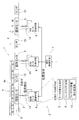
- FIG. 1 shows a linear motor system including a linear motor 1 to be controlled and a transfer control device 2 that controls the linear motor 1.
- the linear motor 1 is a linear synchronous motor (LSM), and moves a plurality of individual motors 3 composed of armatures each capable of functioning as an armature on the primary side of one independent linear motor. It is a discretely arranged linear motor installed at intervals in the direction X.
- LSM linear synchronous motor
- Each individual motor 3 is installed on a common frame 5 having a rail (not shown) of the mover 4.
- a sensor 15 serving as a position detector for detecting the position of the mover 4 is installed for each individual motor 3 in the frame 5.
- the sensor 15 is shown between the individual motors 3 for convenience of illustration. However, in actuality, the sensor 15 is disposed at the same position as the individual motors 3 in the moving direction (X direction). A linear sensor capable of detecting a position in a slightly longer range is used. However, the individual motor 3 and the sensor 15 do not necessarily have to be at the same position, as long as the position of the mover 4 with respect to the individual motor 3 can be detected, and can be made flexible through the processing system.
- the mover 4 is provided with a plurality of N and S magnetic poles made of permanent magnets arranged in the move direction X on the mover base 4a, and is guided by a rail (not shown) provided on the frame 5 so as to be freely advanced and retracted. Is done.
- each individual motor 3 is formed by arranging a plurality of coils 3a and cores 3b serving as magnetic poles of each layer in the moving direction X.
- Each core 3b is constituted by a portion protruding like a comb from a common main body.
- the individual motor 3 may be an armature having a plurality of magnetic poles for each phase (U, V, W phase) and having magnetic poles that are an integral multiple of the number of phases.
- the transfer control device 2 includes a plurality of individual motor control means 6 that respectively control the individual motors 3, and one overall control means 7 that gives a position command to the plurality of individual motor control means 6.
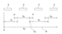
- the overall control means 7 is composed of a weak electric circuit element, a computer, a part of its program, and the like. As shown in FIG. 5, the overall control means 7 has information on the assigned range X i (i: any natural number) obtained by dividing the movement range X 0 of the entire linear motor for each individual motor 3. Since the individual motors 3 are discretely arranged, the assigned range X i is longer than the individual motor 3, and in order to secure a driving force at a certain distance from the individual motor 3, the assigned assigned range X i Are partially overlapped and driven by two individual motors 3.
- the overall control means 7 stores the assigned range X i as described above, and the individual motors 3 that include the command position of the position command input from the higher-level control means (not shown) in the assigned range X i.
- the input position command is converted into a position command corresponding to the individual motor 3 including the assigned range X i and given to the motor control means 6. For example, if the command position R (for example, 1200) of the position command input from the host control means is included in the assigned range X 3 of the third individual motor 3, the assigned range of the third individual motor 3.
- a value (for example, 200) obtained by subtracting the position (for example, 1000) of the origin position O 3 of X 3 is input to the third individual motor control means 6.
- Each individual motor control means 6 is composed of a strong electric motor driving circuit (not shown) for supplying a motor current to the individual motor and a weak electric control unit (not shown) for controlling the motor driving circuit.
- the high-power motor driving circuit includes an inverter provided with a plurality of switching elements, and is connected to a driving DC power source (not shown).
- the weak electric system control unit of the individual motor control means 6 is constituted by a microcomputer, its program, and circuit elements.
- the weak electric system control unit in each individual motor control means 6 includes a motor switching response unit 8, a feedback control unit 9, and a feedback influence gradually changing unit 10.
- the motor switching response unit 8 transmits the input position command to the feedback control unit 9 in response to the position command given from the overall control means 7.
- the feedback control unit 9 includes a position control unit 11, a speed control unit 12, and a current control unit 13 that perform feedback control of position, speed, and current, respectively, as shown in FIG. That is, the feedback control unit 9 has a position loop, a velocity loop, and a current loop. The current loop is not necessarily provided.
- the position control unit 11 performs feedback control of a predetermined position loop gain according to the deviation between the detected value of the sensor 15 that detects the current position of the mover 4 with respect to the individual motor 3 and the command value of the position command.
- the position controller 11 outputs a speed command value as its output.
- the speed control unit 12 has a predetermined speed loop gain according to the deviation between the speed detection value obtained through the speed detection means 16 such as a differentiation means for detecting the speed from the position detection value of the sensor 15 and the speed command value. Perform feedback control.
- the speed control unit 12 outputs a current command value as its output.
- the current control unit 13 detects the drive current applied to the individual motor 3 with current detection means 14 such as a current detector, and determines a current command value corresponding to the deviation between the detected current value and the current command value. Generated using current loop gain to control motor drive current.
- the feedback influence gradual change unit 10 in FIG. 1 performs feedback of the feedback control unit 9 within the vicinity range Xia determined from the control boundary P (FIG. 4) that is a boundary with the adjacent assigned range X i-1 . 4 is a means for gradually increasing the influence of the value from zero to a value used in a general range other than the neighborhood range as the position Q (FIG. 4) deviates from the neighborhood range Xia from the control boundary P. .
- the feedback effect gradual change unit 10 performs the open control in which the influence by the feedback is zero in the setting section X iaa immediately after entering the vicinity range X ia from the control boundary P, and thereafter the influence by the feedback is changed. Strengthen gradually.
- the set section Xiaa may be zero.
- the open control in which the influence of feedback is zero may be instantaneous or can be regarded as zero or zero, and the influence of feedback may be gradually increased from zero.
- the control boundary P has an overlapping range as shown in FIG. 5, the control boundary P is a start position of the assigned range X i in the individual motor 3 to which the mover 4 is transferred.
- the feedback influence gradual change unit 10 is provided as a speed filter interposed between the position control unit 11 and the speed control unit 12, as shown in FIG. That is, the feedback influence gradual change unit 10 changes the speed command value output from the position control unit 11 according to a predetermined relational expression, and outputs it. For the speed command value after the change, the speed control unit 12 performs feedback control based on the current speed detected by the speed detection means 16.
- the above relational expression in the feedback influence gradually changing unit 10 is, for example, the following expression.
- x * new New speed command value
- x * True speed command value
- x Current speed c: Contribution rate (0 ⁇ c ⁇ 1)
- the new speed command value calculated by the above relational expression is input to the input in the speed control unit 12 and the feedback value adding unit 12a.
- the new speed command value becomes the same as the current speed and is open control.
- the contribution rate c is 0, the new speed command value is a true speed command value that is a speed command value output from the position control unit 11, and normal feedback control is performed.
- the feedback influence gradually changing unit 10 gradually changes the contribution ratio c from 1 to 0.
- the feedback influence gradual change unit 10 is provided, and as shown in the conceptual diagram of FIG. 4, in the vicinity range Xia determined from the control boundary P, The influence of the feedback of the feedback control unit 9 is gradually increased from zero to a value used in the normal range other than the neighborhood range Xia as it approaches the position Q outside the neighborhood range Xia from the control boundary P.
- the open control is temporarily performed at the control boundary P, and the control is gradually switched from the open control to the normal feedback control. Therefore, a shock due to a sharp change in command value can be avoided, and the occurrence of shock and vibration in the mover 4 can be suppressed.
- feedback control since feedback control is basically used, positioning and speed control can be performed with higher accuracy than open control.
- the feedback influence gradual changing unit 10 performs open control in which the influence by the feedback is zero in the set section X iaa immediately after entering the vicinity range X ia from the control boundary P, and the control boundary P Since the open control is performed for a while, the above vibration suppression can be performed more effectively.
- the range X iab exceeds the set interval X iaa, although a drawing that performs both the feedback control and the open control, the range X iab is Although it is feedback control, it shows that the influence of feedback changes so as to gradually increase from 0 to 1.
- the above description only the movement in one direction has been described, but when moving in the opposite direction, the same control as in the one direction is performed.
- linear motor 1 to be controlled is discretely arranged with individual motors 3 composed of primary armatures on the fixed side, the amount of coil used is small, and the power feeding system is simpler than when power is supplied to the moving side.
- the advantage of the discretely arranged linear motor can be obtained.
- the overall control unit 7 converts the input position command to the individual motor control unit 6 of the individual motor 3 that includes the command position of the position command input from the host control unit in the assigned range. was to provide Te, enter the same position command to all of the individual motor control means 6 from the central control unit 7, the motor switching response portion 8 of each individual motor control means 6, corresponding to its own responsibility X i It is possible to determine whether or not to perform the motor drive control of the individual motor control means 6 only when applicable.
- FIG. 6 shows an example of the transfer device 21 to which the discretely arranged linear motor transfer control device is applied.
- the conveying device 21 serves as a gantry type loader that loads and unloads a workpiece with respect to a machine tool 20 including a lathe.
- a traveling body 23 is movably installed on a rail (not shown) provided on a horizontal frame 22 along a length direction, and the traveling body 23 is orthogonal to the traveling direction (X direction).
- the front / rear moving table 24 is mounted so as to be movable in the front / rear direction (Z direction).
- a rod-like lifting body 25 is installed on the front / rear moving table 24 so as to be movable up and down, and a loader head 27 having a chuck 26 capable of gripping a workpiece is provided at the lower end of the lifting body 25. The workpiece is transferred between the chuck 26 and the spindle 20a of the machine tool 20.
- a discretely arranged linear motor 1 is provided as a traveling drive source of the traveling body 23.
- the individual motors 3 are arranged on the frame 22 along the length direction, and the movable element 4 is provided on the traveling body 23.
- the discretely arranged linear motor 1 and its transfer control device 2 in this embodiment are as described above with reference to FIGS.
- a control device is placed on the ground system, a high-speed network can be constructed, and simultaneous control of multiple traveling bodies can be easily realized.
Landscapes
- Engineering & Computer Science (AREA)
- Power Engineering (AREA)
- Control Of Linear Motors (AREA)
Abstract
それぞれが独立した1台のリニアモータの一次側の電機子として機能可能な複数の個別モータ3を、可動子4の移動方向Xに間隔を開けて配列した離散配置リニアモータ1を制御する装置であって、各個別モータ3をそれぞれ制御する複数の個別モータ制御手段6と、統括制御手段7とを備える。各個別モータ制御手段6は、統括制御手段7から与えられた位置指令に対して、フィードバック制御するフィードバック制御部9を有する。制御的境界から定められた近傍範囲内において、フィードバックによる影響を、零から徐々に大きくするフィードバック影響徐々変更部10を設ける。
Description
この出願は、2010年10月26日出願の特願2010-239601の優先権を主張するものであり、その全体を参照により本願の一部をなすものとして引用する。
この発明は、工作機械や産業機械における搬送装置の走行駆動や、その各種の機器の駆動に用いられる離散配置リニアモータに適用される離散配置リニアモータの乗り移り制御装置に関する。
リニアモータは、物流装置の搬送台車や工作機械のローダとなる搬送装置等において、その走行駆動等に広く用いられている(例えば、特許文献1)。リニアモータには、リニア誘導モータ(LIM)、リニア同期モータ(LSM)、リニア直流モータ等があるが、長距離の走行システムとして主に使用されているのは、リニア誘導モータである。リニア同期モータは、地上側にマグネットを配置してコイル側を移動する方式が大部分を占める。なお、リニア同期モータにおいて、部分的に地上側に1次コイルを離散配置した例はあるが(例えば、特許文献2)、リニア同期モータは曲線路での補助的な使用であり、基本的にはリニア誘導モータを用いている。
リニア誘導モータは推力が低く、加えて高精度な位置決め制御が困難であり、走行性能の向上が困難であるため、工作機械のローダとなる搬送装置等への適用において、リニア同期モータの採用を試みた。従来のリニア同期モータは、地上側にマグネットを配置してコイル側を移動する方式が大部分を占める。しかし、コイル側を移動させるには、可動子に給電が必要であり、可動子への配線の都合上、無端経路での走行が不能であるなど、走行経路が限られたり、給電系が複雑化したりする。このため、リニア同期モータにおいて、地上側に1次コイルを配置することを試みた。しかし、地上側に1次コイルを配置する場合、従来のリニアモータのように、移動経路の全長に渡って連続してコイルを配置するのでは、コイルの使用量が増えてコストが増大する。
このような課題を解消する同期形リニアモータとして、それぞれが独立した1台のリニアモータの一次側の電機子として機能可能な電機子からなる複数の個別モータを、可動子の移動方向に間隔を開けて配列した離散配置のリニア同期モータを考えた。各個別モータは個別に制御する。可動子は、各個別モータを乗り移って移動することになる。この構成によると、個別モータが離散配置されるため、コイルの使用量が削減でき、コスト低下が図れる。また、走行路として、曲線路や、曲線路と直線路とでなる形状など、走行路の構成が自在となる。
しかし、上記の離散配置リニアモータでは、個別モータ間を乗り移る際に、可動子が振動する。搬送装置の駆動に用いた場合、上記の振動により搬送物に過大な衝撃,振動を加えることになる。そこで、振動の発生原因を調べた結果、一次側と二次側の磁気吸引力が、位置によって変化すること、および速度制御器に対する急峻な速度フィードバックの変化がショックの原因となることがわかった。
この発明の目的は、コイル使用量の削減や給電形式上で有利となる個別モータの離散配置形式を採用しながら、個別モータ間を可動子が乗り移る際の可動子の振動を抑制することができる離散配置リニアモータの乗り移り制御装置を提供することである。
この発明の離散配置リニアモータシステムを実施形態に用いた符号を付して説明する。
この発明の離散配置リニアモータの乗り移り制御装置(2)は、それぞれが独立した1台のリニアモータの一次側の電機子として機能可能な複数の個別モータ(3)を、可動子(4)の移動方向(X)に間隔を開けて配列したリニアモータである離散配置リニアモータ(1)を制御する装置であって、前記各個別モータ(3)をそれぞれ制御する複数の個別モータ制御手段(6)と、これら各個別モータ制御手段に位置指令を与える統括制御手段とを備える。前記各個別モータ制御手段(6)は、前記統括制御手段(7)から与えられた位置指令に応答して位置ループおよび速度ループを有するフィードバック制御で個別モータを駆動するフィードバック制御部(9)と、リニアモータ全体の移動範囲を各個別モータ(3)毎に区分した担当範囲(Xi)の境界となる制御的境界(P)から定められた近傍範囲(Xia)内において、前記フィードバック制御部(9)のフィードバックによる影響を、前記制御的境界(P)から前記近傍範囲(Xia)を外れる位置(Q)に近づくに従って、零から、近傍範囲以外である一般範囲で用いられる値まで徐々に大きくするフィードバック影響徐々変更部(10)とを有する。
この発明の離散配置リニアモータの乗り移り制御装置(2)は、それぞれが独立した1台のリニアモータの一次側の電機子として機能可能な複数の個別モータ(3)を、可動子(4)の移動方向(X)に間隔を開けて配列したリニアモータである離散配置リニアモータ(1)を制御する装置であって、前記各個別モータ(3)をそれぞれ制御する複数の個別モータ制御手段(6)と、これら各個別モータ制御手段に位置指令を与える統括制御手段とを備える。前記各個別モータ制御手段(6)は、前記統括制御手段(7)から与えられた位置指令に応答して位置ループおよび速度ループを有するフィードバック制御で個別モータを駆動するフィードバック制御部(9)と、リニアモータ全体の移動範囲を各個別モータ(3)毎に区分した担当範囲(Xi)の境界となる制御的境界(P)から定められた近傍範囲(Xia)内において、前記フィードバック制御部(9)のフィードバックによる影響を、前記制御的境界(P)から前記近傍範囲(Xia)を外れる位置(Q)に近づくに従って、零から、近傍範囲以外である一般範囲で用いられる値まで徐々に大きくするフィードバック影響徐々変更部(10)とを有する。
この構成によると、フィードバック影響徐々変更部(10)を設け、制御的境界(P)から定められた近傍範囲(Xia)内において、フィードバック制御部(9)のフィードバックによる影響を、前記制御的境界(P)から前記近傍範囲(Xia)を外れる位置(Q)に近づくに従って、零から、一般範囲で用いられる値まで徐々に大きくする。すなわち、制御的境界(P)で一旦オープン制御とし、徐々にオープン制御から通常のフィードバック制御に切り替えして制御する。そのため、急峻な速度フィードバック変化によるショックが回避でき、可動子に衝撃,振動が発生することを抑制することができる。また、基本的にはフィードバック制御とするため、オープン制御に比べて精度の良い位置決めおよび速度制御が行える。制御対象となるリニアモータ(1)は、固定側として、一次側の電機子からなる個別モータ(3)を離散配置したため、コイル使用量が少なくて済み、かつ移動側に給電する場合に比べて給電系が簡素にできると言う離散配置リニアモータ(1)の利点を得ることができる。
前記フィードバック影響徐々変更部(10)は、前記フィードバック制御部(9)の速度ループに入力される速度検出値の影響を、定められた関係式に従って徐々に大きくするのが良い。このように速度検出値の影響を徐々に大きくすることで、上記の振動抑制がより効果的に行える。前記定められた関係式は、次式とするのが良い。

x* new :新しい速度指令値
x*:真の速度指令値
x:現在の速度
c:寄与率(0≦c≦1)
寄与率cは、例えば、位置または時間の関数とする。
x* new :新しい速度指令値
x*:真の速度指令値
x:現在の速度
c:寄与率(0≦c≦1)
寄与率cは、例えば、位置または時間の関数とする。
また、前記フィードバック影響徐々変更部(10)は、例えば、前記制御的境界(P)から前記近傍範囲(Xia )内に入った直後の設定区間(Xiaa)は、前記フィードバックによる影響を零としたオープン制御とするのが良い。制御的境界(P)から暫くはオープン制御とすることで、上記の振動抑制がより効果的に行える。
前記統括制御手段(7)は、リニアモータ全体の移動範囲(X0)を各個別モータ(3)毎に区分した担当範囲(Xi)の情報を有していて、入力された位置指令の指令位置を担当範囲(Xi)に含む個別モータ(3)の個別モータ制御手段(6)に対し、前記入力された位置指令を前記の担当範囲(Xi)として含む個別モータ(3)に対応する位置指令に変換して与える機能を有するものとするのが良い。このように、統括制御手段(7)により位置指令を該当の個別モータ(3)に対応する位置指令に変換すると、複数設けられる個別モータ制御手段(6)が簡素な構成で済む。すなわち、全ての個別モータ制御手段(6)に同じ位置指令を入力し、個々の個別モータ制御手段(6)により自己の担当範囲(Xi)に該当するか否かを判断させ、該当する場合のみ制御動作させることも可能ではあるが、その場合、複数設けられる個別モータ制御手段(6)の全てに、判断処理や位置指令の変換を行う手段が必要となる。統括制御手段(7)にこの機能を持たせると、一つで済み、構成が簡素となる。
請求の範囲および/または明細書および/または図面に開示された少なくとも2つの構成のどのような組合せも、本発明に含まれる。特に、請求の範囲の各請求項の2つ以上のどのような組合せも、本発明に含まれる。
この発明は、添付の図面を参考にした以下の好適な実施形態の説明からより明瞭に理解されるであろう。しかしながら、実施形態および図面は単なる図示および説明のためのものであり、この発明の範囲を定めるために利用されるべきものではない。この発明の範囲は添付の請求の範囲によって定まる。添付図面において、複数の図面における同一の部品番号は、同一部分を示す。
この発明の一実施形態に係る離散配置リニアモータの乗り移り制御装置を備えたリニアモータシステムの概念構成を示すブロック図である。
(A)同リニアモータにおける個別モータの一例の平面図、(B)は同図(A)のII-II線断面図である。
同制御装置のフィードバック制御部の構成とフィードバック影響徐々制御部とを示すブロック図である。
同乗り移り制御装置の制御動作の概念図である。
全体の移動範囲を各個別モータ毎に区分した担当範囲の説明図である。
同離散配置リニアモータの乗り移り制御装置を適用した搬送装置の一例を示す正面図である。
この発明の一実施形態を図1ないし図5と共に説明する。図1は、制御対象となるリニアモータ1と、このリニアモータ1を制御する乗り移り制御装置2とでなるリニアモータシステムを示す。リニアモータ1は、リニア同期モータ(LSM)であって、それぞれが独立した1台のリニアモータの一次側の電機子として機能可能な電機子からなる複数の個別モータ3を、可動子4の移動方向Xに間隔を開けて設置した離散配置リニアモータである。各個別モータ3は、可動子4のレール(図示せず)を有する共通のフレーム5に設置されている。フレーム5には、この他に、各個別モータ3毎に、可動子4の位置を検出する位置検出器となるセンサ15が設置される。
なお、センサ15は、図1では図示の便宜上、個別モータ3間に示しているが、実際には、可動子移動方向(X方向)につき、個別モータ3と同じ位置に配置され、個別モータ3よりも若干長い範囲で位置検出が可能なリニアセンサが用いられる。ただし、個別モータ3とセンサ15とは必ずしも同じ位置でなくても良く、個別モータ3に対する可動子4の位置が検出できれば良く、処理系を介することで、柔軟にできる。可動子4は、永久磁石からなるN,Sの磁極を可動子基体4aに移動方向Xに並べて複数設けたものであり、前記フレーム5に設けられたレール(図示せず)によって進退自在に案内される。
各個別モータ3は、例えば図2(A)および(B)に示すように、各層の磁極となる複数のコイル3aとコア3bを、前記移動方向Xに並べたものである。各コア3bは、共通の本体部からくし歯状に突出した部分で構成される。この例では、3相の交流電流で駆動するものとされ、その各相(U,V,W相)毎に一つの磁極を設けた3極の一次側の電機子とされている。なお、個別モータ3は、各相(U,V,W相)毎に複数の磁極を設け、相数の整数倍の磁極を有する電機子としても良い。
図1において制御系を説明する。乗り移り制御装置2は、各個別モータ3をそれぞれ制御する複数の個別モータ制御手段6と、これら複数の個別モータ制御手段6に位置指令を与える一つの統括制御手段7とを備える。
統括制御手段7は、弱電系の回路素子や、コンピュータおよびそのプログラムの一部等で構成される。統括制御手段7は、図5のように、リニアモータ全体の移動範囲X0を各個別モータ3毎に区分した担当範囲Xi(i:任意の自然数)の情報を有している。個別モータ3は離散配置されているため、担当範囲Xiは個別モータ3よりも長い範囲であり、また個別モータ3からある程度離れた位置で駆動力を確保するために、隣り合う担当範囲Xiは一部を重複させ、2台の個別モータ3で駆動を行うようにしている。
統括制御手段7は、上記のように担当範囲Xiを記憶していて、上位制御手段(図示せず)から入力された位置指令の指令位置を、担当範囲Xiに含む個別モータ3の個別モータ制御手段6に対し、前記入力された位置指令を前記の担当範囲Xiとして含む個別モータ3に対応する位置指令に変換して与える。例えば、上位制御手段から入力された位置指令の指令位置R (例えば、1200)が、第3番目の個別モータ3の担当範囲X3に含まれるとすると、第3番目の個別モータ3の担当範囲X3の原点位置O3の位置(例えば、1000)を差し引いた値(例えば、200)を、第3の番目の個別モータ制御手段6に対して入力する。
各個別モータ制御手段6は、モータ電流を個別モータに流す強電系のモータ駆動回路(図示せず)と、このモータ駆動回路を制御する弱電系の制御部(図示せず)とでなる。強電系のモータ駆動回路は、複数のスイッチング素子を設けたインバータ等からなり、駆動用の直流電源(図示せず)に接続されている。個別モータ制御手段6の前記弱電系の制御部は、マイクロコンピュータおよびそのプログラムや、回路素子によって構成される。
各個別モータ制御手段6における前記弱電系の制御部に、モータ切替え応答部8と、フィードバック制御部9と、フィードバック影響徐々変更部10とを有する。モータ切替え応答部8は、統括制御手段7から与えられた位置指令に応答して、入力された位置指令をフィードバック制御部9へ伝える。
フィードバック制御部9は、図3に一例を示すように、それぞれ位置,速度,電流のフィードバック制御を行う位置制御部11と、速度制御部12と、電流制御部13とを有している。すなわち、フィードバック制御部9は、位置ループ、速度ループ、および電流ループを有する。電流ループは必ずしも設けなくても良い。位置制御部11は、個別モータ3に対する可動子4の現在位置を検出する前記センサ15の検出値と位置指令の指令値との偏差に応じ、定められた位置ループゲインのフィードバック制御を行う。位置制御部11は、その出力として速度指令値を出力する。
速度制御部12は、センサ15の位置検出値から速度を検出する微分手段等の速度検出手段16を経て得られる速度検出値と、速度指令値との偏差に応じ、定められた速度ループゲインのフィードバック制御を行う。速度制御部12は、その出力として電流指令値を出力する。電流制御部13は、個別モータ3に印加される駆動電流を電流検出器等の電流検出手段14で検出して、電流検出値と電流指令値との偏差に応じた電流指令値を、定められ電流ループゲインを用いて生成し、モータ駆動電流を制御する。
図1のフィードバック影響徐々変更部10は、隣の担当範囲Xi-1との境界となる制御的境界P(図4)から定められた近傍範囲Xia内において、前記フィードバック制御部9のフィードバックによる影響を、前記制御的境界Pから前記近傍範囲Xiaを外れる位置Q(図4)に近づくにしたがって、零から、近傍範囲以外である一般範囲で用いられる値まで徐々に大きくする手段である。このフィードバック影響徐々変更部10は、前記制御的境界Pから前記近傍範囲Xia内に入った直後の設定区間Xiaaは、前記フィードバックによる影響を零としたオープン制御とし、その後にフィードバックによる影響を徐々に強める。なお、前記設定区間Xiaaは零としても良い。すなわち、前記フィードバックによる影響を零としたオープン制御は、零または零とみなせる瞬時とし、フィードバックによる影響を零から次第に大きくしても良い。制御的境界Pは、図5のような重なり範囲を有する場合、可動子4が乗り移って来る個別モータ3における担当範囲Xiの始端位置である。
フィードバック影響徐々変更部10は、具体的には図3に示すように、位置制御部11と速度制御部12との間に介在させた速度フィルタとして設ける。すなわち、フィードバック影響徐々変更部10は、位置制御部11の出力する速度指令値を、定められた関係式によって変更して出力する。その変更後の速度指令値に対して、速度制御部12が、速度検出手段16の検出した現在速度によってフィードバック制御を行う。
フィードバック影響徐々変更部10における上記関係式は、例えば次式とされる。

x* new:新しい速度指令値
x*:真の速度指令値
x:現在の速度
c:寄与率(0≦c≦1)
x* new:新しい速度指令値
x*:真の速度指令値
x:現在の速度
c:寄与率(0≦c≦1)
上記の関係式により演算された新しい速度指令値が、速度制御部12における入力とフィードバック値の加算部12aに入力される。なお、上記の式では、寄与率cは、フィードバック影響徐々変更部10の有効時間T(この時間分、スムーズ切替えが有効となる)と、可動子4が担当範囲に入った時の時刻(=0)を起点とする時刻または経過時間tとによる時間の関数としたが、可動子4の位置の関数としても良い。
上記の関係式において、寄与率cが1の場合は、新しい速度指令値は現在の速度と同じとなり、オープン制御となる。寄与率cが0の場合は、新しい速度指令値は、位置制御部11から出力される速度指令値である真の速度指令値となり、通常のフィードバック制御となる。フィードバック影響徐々変更部10は、この寄与率cを、1から0へ次第に変化させる。
上記構成の離散配置リニアモータ1の乗り移り制御装置2によると、フィードバック影響徐々変更部10を設け、図4に概念図で示すように、制御的境界Pから定められた近傍範囲Xia内において、フィードバック制御部9のフィードバックによる影響を、制御的境界Pから近傍範囲Xiaを外れる位置Qに近づくに従って、零から、近傍範囲Xia以外の通常範囲で用いられる値まで徐々に大きくする。すなわち、制御的境界Pで一旦オープン制御とし、徐々にオープン制御から通常のフィードバック制御に切り替えて制御する。そのため、急峻な指令値変化によるショックが回避でき、可動子4に衝撃,振動が発生することを抑制することができる。また、基本的にはフィードバック制御とするため、オープン制御に比べて精度の良い位置決めおよび速度制御が行える。
また、前記フィードバック影響徐々変更部10は、制御的境界Pから前記近傍範囲Xia内に入った直後の設定区間Xiaaでは、前記フィードバックによる影響を零としたオープン制御としており、制御的境界Pから暫くはオープン制御とするため、上記の振動抑制がより効果的に行える。なお、図4において、上記近傍範囲Xiaのうち、設定区間Xiaaを超えた範囲Xiabでは、フィードバック制御とオープン制御との双方を行うような図となっているが、この範囲Xiabは、フィードバック制御ではあるが、フィードバックによる影響が0から1まで次第に大きくなるように変化することを示している。なお、上記の説明は、一方向への移動についてのみ説明したが、逆方向に移動する場合も、前記一方向への制御と同様の制御を行う。
制御対象となるリニアモータ1は、固定側として、一次側の電機子からなる個別モータ3を離散配置したため、コイル使用量が少なくて済み、かつ移動側に給電する場合に比べて給電系が簡素にできると言う離散配置リニアモータの利点を得ることができる。
なお、上記実施形態では、統括制御手段7が、上位制御手段から入力された位置指令の指令位置を担当範囲に含む個別モータ3の個別モータ制御手段6に対し、入力された位置指令を変換して与えるようにしたが、統括制御手段7から全ての個別モータ制御手段6に同じ位置指令を入力し、個々の個別モータ制御手段6のモータ切替え応答部8により、自己の担当範囲Xiに該当するか否かを判断させ、該当する場合のみ、その個別モータ制御手段6のモータ駆動制御を行わせるようにしても良い。
図6は、この離散配置リニアモータの乗り移り制御装置を適用した搬送装置21の一例を示す。この搬送装置21は、旋盤等からなる工作機械20に対してワークの搬入搬出を行うガントリ型のローダとなるものである。この搬送装置21は、水平なフレーム22に長さ方向に沿って設けられたレール(図示せず)に走行体23が走行自在に設置され、走行体23に、走行方向(X方向)と直交する方向である前後方向(Z方向)に移動自在に前後移動台24が搭載されている。前後移動台24にロッド状の昇降体25が昇降自在に設置され、昇降体25の下端にワークを把持可能なチャック26を有するローダヘッド27が設けられている。チャック26と、工作機械20の主軸20aとの間で、ワークの受渡しが行われる。
上記走行体23の走行駆動源として、離散配置リニアモータ1が設けられている。離散配置リニアモータ1は、その各個別モータ3が、フレーム22に長さ方向に沿って配列され、走行体23に前記可動子4が設けられている。この実施形態における離散配置リニアモータ1、およびその乗り移り制御装置2は、特に説明した事項の他は、図1~図5と共に前述したとおりである。
また、地上系に制御装置を置くことから、高速なネットワークが構築でき、複数の走行体の同時制御が容易に実現できる。
以上のとおり、図面を参照しながらこの発明の好適な実施形態を説明したが、この発明の趣旨を逸脱しない範囲内で、種々の追加、変更または削除が可能である。したがって、そのようなものもこの発明の範囲内に含まれる。
1 離散配置リニアモータ
2 乗り移り制御装置
3 個別モータ
4 可動子
6 個別モータ制御手段
7 統括制御手段
8 モータ切替え応答部
9 フィードバック制御部
10 フィードバック影響徐々変更部
15 センサ
20 工作機械
21 搬送装置
P 制御的境界
Q 近傍範囲を外れる位置
Xi 担当範囲
Xia 近傍範囲
Xiaa 設定区間
2 乗り移り制御装置
3 個別モータ
4 可動子
6 個別モータ制御手段
7 統括制御手段
8 モータ切替え応答部
9 フィードバック制御部
10 フィードバック影響徐々変更部
15 センサ
20 工作機械
21 搬送装置
P 制御的境界
Q 近傍範囲を外れる位置
Xi 担当範囲
Xia 近傍範囲
Xiaa 設定区間
Claims (5)
- それぞれが独立した1台のリニアモータの一次側の電機子として機能可能な複数の個別モータを、可動子の移動方向に間隔を開けて配列した離散配置リニアモータを制御する装置であって、
前記各個別モータをそれぞれ制御する複数の個別モータ制御手段と、これら各個別モータ制御手段に位置指令を与える統括制御手段とを備え、
前記各個別モータ制御手段は、
前記統括制御手段から与えられた位置指令に応答して位置ループおよび速度ループを有するフィードバック制御で個別モータを駆動するフィードバック制御部と、
リニアモータ全体の移動範囲を各個別モータ毎に区分した担当範囲の境界となる制御的境界から定められた近傍範囲内において、前記フィードバック制御部のフィードバックによる影響を、前記制御的境界から前記近傍範囲を外れる位置に近づくに従って、零から、近傍範囲以外である一般範囲で用いられる値まで徐々に大きくするフィードバック影響徐々変更部とを有する離散配置リニアモータの乗り移り制御装置。 - 前記フィードバック影響徐々変更部は、前記フィードバック制御部の速度ループに入力される速度検出値の影響を、定められた関係式に従って徐々に大きくする請求項1記載の離散配置リニアモータの乗り移り制御装置。
- 前記定められた関係式として、次式を用いる請求項2記載の離散配置リニアモータの乗り移り制御装置。

x* new:新しい速度指令値
x*:真の速度指令値
x:現在の速度
c:寄与率(0≦c≦1) - 前記フィードバック影響徐々変更部は、前記制御的境界から前記近傍範囲内に入った直後の設定区間は、前記フィードバックによる影響を零としたオープン制御とする請求項1ないし請求項3のいずれか1項に記載の離散配置リニアモータの乗り移り制御装置。
- 前記統括制御手段は、リニアモータ全体の移動範囲を各個別モータ毎に区分した担当範囲の情報を有していて、入力された位置指令の指令位置を担当範囲に含む個別モータの個別モータ制御手段に対し、前記入力された位置指令を前記の担当範囲として含む個別モータに対応する位置指令に変換して与える請求項1ないし請求項3のいずれか1項に記載の離散配置リニアモータの乗り移り制御装置。
Priority Applications (1)
| Application Number | Priority Date | Filing Date | Title |
|---|---|---|---|
| JP2012540746A JP5532140B2 (ja) | 2010-10-26 | 2011-09-27 | 離散配置リニアモータの乗り移り制御装置 |
Applications Claiming Priority (2)
| Application Number | Priority Date | Filing Date | Title |
|---|---|---|---|
| JP2010239601 | 2010-10-26 | ||
| JP2010-239601 | 2010-10-26 |
Publications (1)
| Publication Number | Publication Date |
|---|---|
| WO2012056843A1 true WO2012056843A1 (ja) | 2012-05-03 |
Family
ID=45993573
Family Applications (1)
| Application Number | Title | Priority Date | Filing Date |
|---|---|---|---|
| PCT/JP2011/072004 Ceased WO2012056843A1 (ja) | 2010-10-26 | 2011-09-27 | 離散配置リニアモータの乗り移り制御装置 |
Country Status (3)
| Country | Link |
|---|---|
| JP (1) | JP5532140B2 (ja) |
| TW (1) | TWI540824B (ja) |
| WO (1) | WO2012056843A1 (ja) |
Cited By (3)
| Publication number | Priority date | Publication date | Assignee | Title |
|---|---|---|---|---|
| JP2017042029A (ja) * | 2015-08-21 | 2017-02-23 | 村田機械株式会社 | リニアモータシステム |
| CN109217768A (zh) * | 2017-06-29 | 2019-01-15 | B和R工业自动化有限公司 | 长定子线性电动机和用于移动长定子线性电动机的运输单元的方法 |
| JPWO2021131542A1 (ja) * | 2019-12-27 | 2021-07-01 |
Citations (3)
| Publication number | Priority date | Publication date | Assignee | Title |
|---|---|---|---|---|
| JPH04200291A (ja) * | 1990-11-29 | 1992-07-21 | Sumitoku Eng Kk | リニアdcモータ駆動方法 |
| JPH06209502A (ja) * | 1993-01-06 | 1994-07-26 | Toshiba Corp | 磁気浮上式鉄道における駆動制御装置 |
| JP2010130740A (ja) * | 2008-11-26 | 2010-06-10 | Toshiba Mach Co Ltd | マグネット可動型リニアモータ |
-
2011
- 2011-09-27 JP JP2012540746A patent/JP5532140B2/ja active Active
- 2011-09-27 WO PCT/JP2011/072004 patent/WO2012056843A1/ja not_active Ceased
- 2011-10-19 TW TW100137908A patent/TWI540824B/zh active
Patent Citations (3)
| Publication number | Priority date | Publication date | Assignee | Title |
|---|---|---|---|---|
| JPH04200291A (ja) * | 1990-11-29 | 1992-07-21 | Sumitoku Eng Kk | リニアdcモータ駆動方法 |
| JPH06209502A (ja) * | 1993-01-06 | 1994-07-26 | Toshiba Corp | 磁気浮上式鉄道における駆動制御装置 |
| JP2010130740A (ja) * | 2008-11-26 | 2010-06-10 | Toshiba Mach Co Ltd | マグネット可動型リニアモータ |
Cited By (6)
| Publication number | Priority date | Publication date | Assignee | Title |
|---|---|---|---|---|
| JP2017042029A (ja) * | 2015-08-21 | 2017-02-23 | 村田機械株式会社 | リニアモータシステム |
| CN109217768A (zh) * | 2017-06-29 | 2019-01-15 | B和R工业自动化有限公司 | 长定子线性电动机和用于移动长定子线性电动机的运输单元的方法 |
| CN109217768B (zh) * | 2017-06-29 | 2023-03-31 | B和R工业自动化有限公司 | 长定子线性电动机和用于移动长定子线性电动机的运输单元的方法 |
| JPWO2021131542A1 (ja) * | 2019-12-27 | 2021-07-01 | ||
| WO2021131542A1 (ja) * | 2019-12-27 | 2021-07-01 | パナソニックIpマネジメント株式会社 | リニアモータシステム |
| JP7565508B2 (ja) | 2019-12-27 | 2024-10-11 | パナソニックIpマネジメント株式会社 | リニアモータシステム |
Also Published As
| Publication number | Publication date |
|---|---|
| JP5532140B2 (ja) | 2014-06-25 |
| TWI540824B (zh) | 2016-07-01 |
| JPWO2012056843A1 (ja) | 2014-03-20 |
| TW201230662A (en) | 2012-07-16 |
Similar Documents
| Publication | Publication Date | Title |
|---|---|---|
| US10300793B2 (en) | System and method for providing power to a moving element | |
| KR101480785B1 (ko) | 반송 시스템 | |
| JPWO2012056842A1 (ja) | 離散配置リニアモータシステム | |
| CN110611458B (zh) | 长定子直线电机的短路制动 | |
| TWI535181B (zh) | Linear motor control device | |
| JP6521772B2 (ja) | 搬送システム及びその制御方法、並びに台車及びその制御方法 | |
| FI119862B (fi) | Taajuusmuuttajien tai invertterien rinnankäytön ohjaus | |
| JP2006501799A (ja) | 磁力を利用した、浮遊、誘導及び推進輸送手段 | |
| JP4427544B2 (ja) | 可動負荷用の無接触エネルギー供給部 | |
| JPWO2012056839A1 (ja) | ユニット構成型工作機械・搬送装置・加工設備 | |
| JP5532140B2 (ja) | 離散配置リニアモータの乗り移り制御装置 | |
| JP5423901B2 (ja) | 搬送システム | |
| TWI526341B (zh) | Handling system | |
| JP2012095414A (ja) | リニアモータおよびこれを用いた搬送システム | |
| JP2009303377A (ja) | リニアモータ用ブレーキ回路 |
Legal Events
| Date | Code | Title | Description |
|---|---|---|---|
| 121 | Ep: the epo has been informed by wipo that ep was designated in this application |
Ref document number: 11835983 Country of ref document: EP Kind code of ref document: A1 |
|
| ENP | Entry into the national phase |
Ref document number: 2012540746 Country of ref document: JP Kind code of ref document: A |
|
| NENP | Non-entry into the national phase |
Ref country code: DE |
|
| 122 | Ep: pct application non-entry in european phase |
Ref document number: 11835983 Country of ref document: EP Kind code of ref document: A1 |