WO2012046296A1 - 空間映像表示装置 - Google Patents
空間映像表示装置 Download PDFInfo
- Publication number
- WO2012046296A1 WO2012046296A1 PCT/JP2010/067438 JP2010067438W WO2012046296A1 WO 2012046296 A1 WO2012046296 A1 WO 2012046296A1 JP 2010067438 W JP2010067438 W JP 2010067438W WO 2012046296 A1 WO2012046296 A1 WO 2012046296A1
- Authority
- WO
- WIPO (PCT)
- Prior art keywords
- light reflecting
- aggregate
- line
- light
- sight
- Prior art date
- Legal status (The legal status is an assumption and is not a legal conclusion. Google has not performed a legal analysis and makes no representation as to the accuracy of the status listed.)
- Ceased
Links
Images









Classifications
-
- G—PHYSICS
- G02—OPTICS
- G02B—OPTICAL ELEMENTS, SYSTEMS OR APPARATUS
- G02B27/00—Optical systems or apparatus not provided for by any of the groups G02B1/00 - G02B26/00, G02B30/00
- G02B27/02—Viewing or reading apparatus
- G02B27/022—Viewing apparatus
-
- G—PHYSICS
- G02—OPTICS
- G02B—OPTICAL ELEMENTS, SYSTEMS OR APPARATUS
- G02B17/00—Systems with reflecting surfaces, with or without refracting elements
- G02B17/006—Systems in which light light is reflected on a plurality of parallel surfaces, e.g. louvre mirrors, total internal reflection [TIR] lenses
Definitions
- the present invention relates to a spatial video display device that displays video in a space.
- Patent Document 1 an image of an object, which is a projection object placed on one side of an element, is formed on a position that is a surface object on the opposite side of the element by using a reflection-type plane-symmetric imaging element.
- a spatial video display device is disclosed.
- the reflection-type plane-symmetric imaging element used in this spatial image display device has a plurality of holes that penetrate a predetermined base in the thickness direction, and is a unit optical system that is composed of two mirror surface elements orthogonal to the inner wall of each hole An element is formed, and when light is transmitted from one surface direction of the substrate to the other surface direction through the hole, the light is reflected once by each of the two mirror elements.
- the light emitted from the projection is reflected by one of the two mirror elements when passing through the unit optical element of the reflective surface-symmetric imaging element, and then reflected by the mirror surface to become reflected light.
- the light is reflected by the other of the two specular elements of the unit optical element, and the projection object is imaged at a position reflected on the virtual mirror.
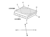
- FIGS. 1 to 3 are diagrams showing the configuration of a reflection-type plane-symmetric imaging element (hereinafter referred to as a light reflection optical element) proposed in Patent Document 2.
- FIG. FIG. 1 is an external view of a light reflecting optical element
- FIG. 2 is an external view of a rectangular parallelepiped material constituting the light reflecting optical element
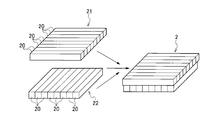
- FIG. 3 is an external view showing a combination of two mirror sheets forming the light reflecting optical element.
- the light reflecting optical element 2 has two mirror sheets 21 and 22 each formed by closely contacting a large number of rod-shaped rectangular parallelepiped materials 20 in parallel.
- the rectangular parallelepiped material 20 is a long member, and is represented by transparent acrylic whose one side of a rectangular cross section in the direction perpendicular to the longitudinal direction, that is, in the short direction, is several hundred ⁇ m to several cm. Made of plastic or glass rod. The length varies depending on the size of the image to be projected, but is about several tens mm to several m. Note that three of the four surfaces extending in the longitudinal direction are surfaces used for light transmission or reflection, and thus are in a smooth state. About 100 to 20000 rectangular parallelepiped materials 20 are used for each of the mirror sheets 21 and 22.
- a light reflecting film 23 is formed on one surface of the rectangular parallelepiped material 20 extending in the longitudinal direction, thereby forming a light reflecting surface.
- the light reflecting film 23 is formed by vapor deposition or sputtering of aluminum or silver.
- a mirror sheet 21 is formed by bringing the opposite surface 24 opposite to the surface on which the light reflecting film 23 of one rectangular parallelepiped member 20 is formed into close contact with the light reflecting surface 23 of another rectangular parallelepiped member 20. , 22 are formed. As shown in FIG. 3, the mirror sheets 21 and 22 are bonded together in a state in which one of the rectangular parallelepiped materials 20 is rotated by 90 degrees so that the parallel directions of the rectangular parallelepiped materials 20 intersect, thereby forming the light reflecting optical element 2. Is done.
- the object 1 is disposed on one surface side of the light reflecting optical element 2, and the light reflecting optical element 2 includes the object 1 from the object 1.
- Light is incident obliquely.
- the observer's eyes E are positioned on the other surface side of the light reflecting optical element 2, and a real image 3, that is, a spatial image is formed at a spatial position that is plane-symmetric with the object 1 with respect to the light reflecting optical element 2.
- the lower end A and the upper end A ′ which are both ends of the light reflecting optical element 2 in FIG. 4, correspond to the opposing angles A and A ′ of the light reflecting optical element 2 in FIG. 1. More specifically, as shown in FIG.
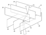
- each light reflecting surface 23 of the light reflecting optical element 2 has 1 each. It is designed to create a mirror image by reflecting twice, that is, twice.
- the present invention has been made in view of the above circumstances, and an example of the problem is a spatial video display that can ensure the brightness of a spatial video even if the line of sight is shifted from the design line of sight to the horizontal direction. To provide an apparatus.
- one aspect of the present invention is a spatial image display device including a light reflecting optical element that reflects light from a substantial part toward an observer, and the light reflecting optical element includes: The first assembly and the second assembly in which a plurality of longitudinal members having one light reflecting surface are arranged so that the light reflecting surfaces are in the same direction are overlapped so that the light reflecting surfaces are orthogonal to each other.
- Each of the plurality of longitudinal members constituting the first assembly and the second assembly is composed of a translucent rectangular parallelepiped having four surfaces extending in the longitudinal direction, and one of the four surfaces is The light reflecting surface, and in each of the first aggregate and the second aggregate, the light reflecting surface of one rectangular parallelepiped and the surface facing the light reflecting surface of the adjacent rectangular parallelepiped are in contact with each other.
- the rectangular parallelepiped is arranged to receive light from the entity part.
- Each of the first aggregate and the second light aggregate is reflected once on the light reflecting surface to form a real image, and the light reflecting surface of the first aggregate is moved from the line of sight of the observer.
- the light reflecting surfaces of the second assembly are obliquely arranged from the left back direction to the right front direction as viewed from the left, and the light reflecting surface of the second aggregate is directed from the right back direction to the left front direction as viewed from the line of sight of the observer.
- the thickness of the first assembly which is the length of the light reflecting surface of the first assembly in the short direction, is the left direction when viewed from the observer's line of sight
- the thickness of the second aggregate which is the length in the short direction of the light reflecting surface of the second aggregate, is the direction of the line of sight of the observer. It is formed so as to become thinner from the right direction to the left direction when viewed from the side.
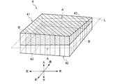
- FIG. 1 is an external perspective view of a light reflecting optical element according to an embodiment of the present invention.
- FIG. 7 is a top view, a side view, and a front view of a first mirror sheet constituting the light reflecting optical element in FIG. 6.
- FIG. 7 is a top view, a side view, and a front view of a second mirror sheet constituting the light reflecting optical element of FIG. 6. It is a figure explaining the effect
- the spatial image display device using the light reflecting optical element according to the embodiment of the present invention the state where the light from the substance is divided into left and right light and reflected twice by the light reflecting optical element to form a real image, It is the figure seen from the front surface, the side surface, and the upper surface.
- the state where the light from the substance is divided into light in the front-rear direction and reflected twice by the light reflecting optical element to form a real image It is the figure seen from the front surface, the side surface, and the upper surface. It is a figure which shows the horizontal angle dependence of the light utilization efficiency of the light reflection optical element which concerns on embodiment of this invention. It is a figure which shows the perpendicular angle dependence of the light utilization efficiency of the light reflection optical element which concerns on embodiment of this invention. It is a figure which shows the horizontal angle dependence of the light utilization efficiency of the light reflection optical element of FIG.
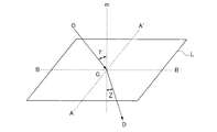
- FIG. 20 is a top view including a reference plane L in FIG. 19, a side view including AA ′ and a normal line m, and a plan view including OC and BB ′. It is explanatory drawing for calculating the thickness of the light reflection optical element which concerns on embodiment of this invention.
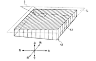
- FIG. 6 is an external perspective view of the light reflecting optical element 4 according to the embodiment of the present invention.
- the light reflecting optical element 4 according to the present embodiment is formed as shown in FIG. 1 to FIG. 3 (however, reference numeral 2 shown in FIG. 1 to FIG. 3 is assigned reference numeral 4 and reference numeral 20 is assigned reference numeral 20). 40, reference numeral 21 is replaced with reference numeral 41, reference numeral 22 is replaced with reference numeral 42, reference numeral 23 is replaced with reference numeral 43, and reference numeral 24 is replaced with reference numeral 44).
- the front-rear and left-right directions and the direction of AA 'shown in FIG. 1 are the same as the front-rear and left-right directions and the direction of AA' shown in FIG.
- the front-rear direction on the bonding surface (hereinafter also referred to as a reference surface) L of the mirror sheets 41 and 42 is defined as the AA ′ direction
- the left-right direction is defined as the BB ′ direction.
- the mirror sheet 41 is also referred to as a first mirror sheet
- the mirror sheet 42 is also referred to as a second mirror sheet
- the light reflecting surface 43 of the mirror sheet 41 is a first light reflecting surface
- the light reflecting surface 43 of the mirror sheet 42 is second light reflecting. Also called a surface.
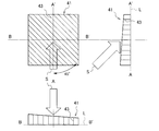
- FIGS. 7 is an external perspective view of the mirror sheet 41
- FIG. 8 is a top view, a side view, and a front view of the mirror sheet 41
- FIG. 9 is an external perspective view of the mirror sheet 42
- FIG. It is a top view, a side view, and a front view.
- the design line-of-sight direction S in the present embodiment is, as shown in FIGS. 7 to 10, the AA ′ direction of the reference plane L (from A to A ′, that is, from the front to the back). The direction seen from diagonally above.
- each first light reflecting surface 43 of the mirror sheet 41 is disposed so as to intersect the AA ′ direction and the BB ′ direction at 45 degrees, and each second light reflecting surface of the mirror sheet 42.
- the surface 43 is orthogonal to the arrangement direction of the first light reflecting surfaces 43 and is arranged to intersect the AA ′ direction and the BB ′ direction at 45 degrees. That is, in the present embodiment, the first light reflecting surfaces 43 of the mirror sheet 41 are arranged from the left back direction to the right front direction so that they are parallel to each other, and the second light reflecting surface 43 of the mirror sheet 42 is also provided. Are arranged from the right back direction to the left front direction so that they are parallel to each other.
- the longitudinal direction of the light reflecting surfaces 43 constituting the mirror sheets 41 and 42 is the arrangement direction of the light reflecting surfaces 43, and the short direction of the light reflecting surfaces 43 constituting the mirror sheets 41 and 42 is the light. It is the height (thickness) of the reflecting surface 43.
- the light reflecting optical element 4 is characterized in that the thicknesses of the two mirror sheets 41 and 42 are not uniform. That is, the thickness of the mirror sheet 41 on which the first light reflecting surface 43 is arranged from the left back direction toward the right front direction becomes thinner from the left direction toward the right direction as shown in FIGS. Thus, it is formed so as to become thinner from the front direction toward the back direction.
- the thickness of the mirror sheet 42 on which the second light reflecting surface 43 is arranged from the right back direction toward the left front direction becomes thinner from the right direction toward the left direction. Thus, it is formed so as to become thinner from the front direction toward the back direction.
- the thickness of the mirror sheets 41 and 42 of the light reflecting optical element 4 continuously changes in the left-right direction and the front-rear direction, but to be precise, it is linear as shown in FIGS. Instead of changing to, the curve changes based on the formula (4) relating to the thickness of the light reflecting optical element 4 described later.
- Various methods are conceivable for producing the light reflecting optical element 4.
- the mirror sheets 41 and 42 are formed with the thickness of the thickest part, and then both surfaces of the mirror sheets 41 and 42 are polished and gradually thinned to obtain a desired thickness. Also good.
- the line of sight from the observer E is incident on the central part and the peripheral part of the light reflecting optical element 4 on the extension of the spatial image 3, bent by the light reflecting optical element 4, and the spatial image 3.
- the substantial part (display part) 1 in a plane symmetrical position with respect to the light reflecting optical element 4.
- the thicknesses of the light reflecting surfaces 43 of the mirror sheets 41 and 42 constituting the light reflecting optical element 4 in the front-rear direction and the left-right direction are as shown in FIGS.
- the luminance distribution of the spatial image 3 observed from the observer E becomes close to the luminance distribution of the entity part 1.
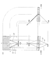
- FIG. 12 shows a state in which the light from the entity 1 is divided into left and right light and reflected twice by the light reflecting optical element 4 to form a real image 3 in the spatial image display device using the light reflecting optical element 4. It is the figure seen from the front surface (BB 'cross section), the side surface (AA' cross section), and the upper surface.
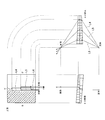
- FIG. 13 shows a state in which the light from the entity 1 is split into light in the front-rear direction and reflected twice by the light reflecting optical element 4 to form a real image 3 in the spatial image display device using the light reflecting optical element 4.
- FIG. 5 is a view of the above as viewed from the front (BB ′ cross section), the side (AA ′ cross section), and the top surface.
- the light emitted from the entity 1 is reflected by the light reflecting surface 43 of the mirror sheet 42 which is the first layer of the light reflecting optical element 4, and is disposed 90 degrees orthogonal to the first layer mirror sheet 42. It is reflected again by the light reflecting surface 43 of the mirror sheet 41 of the second layer, and forms a real image 3 at a position where the reference surface L is symmetrical with the entity 1.
- the light L1 emitted in the left direction from the designed line-of-sight direction S is reflected by the light beam and the mirror sheet 42 compared to the light L2 emitted in the designed line-of-sight direction S. Since the angle formed with the surface 43 is increased, the mirror sheet 42 cannot enter deeper than the light L2 emitted in the design line-of-sight direction S. Therefore, it is necessary to gradually reduce the thickness of the mirror sheet 42 from the design line-of-sight direction S to the left.
- the light L3 emitted in the right direction from the designed line-of-sight direction S has a smaller angle between the light beam and the light reflecting surface 43 of the mirror sheet 42 than the light L2 emitted in the designed line-of-sight direction S. Therefore, compared with the light L2 emitted in the design line-of-sight direction S, the mirror sheet 42 can be deeply penetrated. Accordingly, it is necessary to gradually increase the thickness of the mirror sheet 42 from the design line-of-sight direction S to the right. From the above, in the present embodiment, with respect to the mirror sheet 42 in which the light reflecting surface 43 is disposed from the right back direction toward the left front direction, the thickness of the mirror sheet 42 from the right direction toward the left direction. Is formed so as to become thinner gradually.
- the light L4 emitted in the back direction from the design line-of-sight direction S is light and the light reflecting surface of the mirror sheet 42 compared to the light L5 emitted in the design line-of-sight direction S. Since the angle formed with 43 becomes larger, it cannot enter the mirror sheet 42 deeper than the light L5 emitted in the designed line-of-sight direction S. Therefore, it is necessary to gradually reduce the thickness of the mirror sheet 42 from the designed line-of-sight direction S to the back direction.
- the angle formed between the light reflection surface 43 of the mirror sheet 42 and the light L6 emitted in the near direction from the designed line-of-sight direction S is smaller than the light L5 emitted in the designed line-of-sight direction S. Therefore, compared with the light L5 emitted in the designed line-of-sight direction S, the mirror sheet 42 can be deeply penetrated. Therefore, it is necessary to gradually increase the thickness of the mirror sheet 42 from the design line-of-sight direction S to the front direction. From the above, in the present embodiment, with respect to the mirror sheet 42 in which the light reflecting surface 43 is arranged from the right back direction toward the left front direction, the thickness of the mirror sheet 42 from the front direction toward the back direction. Is formed so as to become thinner gradually.
- the thickness of the mirror sheet 42 has been described in detail above with reference to FIGS. 12 and 13, the same applies to the thickness of the mirror sheet 41. That is, when the angle formed between the light beam and the light reflection surface 43 of the mirror sheet 41 is increased, the light reflection surface 43 is arranged from the left back direction toward the right front side because it cannot enter the mirror sheet 41 deeply. With respect to the mirror sheet 41, the thickness of the mirror sheet 41 gradually decreases from the left to the right, and the thickness of the mirror sheet 41 gradually decreases from the front to the back. Is formed.
- the spatial image display device using the light reflecting optical element 4 of the present embodiment even if the observer shifts the line of sight in the left-right direction with respect to the designed line-of-sight direction S, the spatial image is uniformly bright. Now you can see it. Further, even when the observer shifts his / her line of sight in the front-rear direction with respect to the designed line-of-sight direction S, the viewer can view the spatial image with uniform brightness.
- the mirror sheet 41 is placed on the top and the mirror sheet 42 is placed on the top and bottom.
- the thickness of the mirror sheet is determined between the light beam and the light reflecting surface 43 of the mirror sheet. Since it is determined according to the angle formed, it may be bonded upside down.
- the mirror sheet 42 may be bonded to the top and the mirror sheet 41 may be bonded to the bottom. In this case, the same action is exhibited.
- FIG. 14 and 15 show the light-reflecting optical element 4 of the present embodiment (more precisely, the light-reflecting optical element 4 composed of mirror sheets 41 and 42 whose thickness is calculated based on formula (4) described later). It is a figure which shows the utilization efficiency of light.
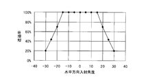
- FIG. 14 is a graph showing the horizontal angle dependency of the ratio (also referred to as transmittance) of the light that is reflected once by the mirror sheets 41 and 42 and passes through the light reflecting optical element 4.
- FIG. 4 is a graph showing the vertical angle dependence of the ratio of light that is reflected once by the mirror sheets 41 and 42 and passes through the light reflecting optical element 4 (also referred to as transmittance).
- the incident angle of 0 degrees in the horizontal direction means the design line-of-sight direction S. Therefore, in FIG. 14, the line of sight is shifted by about ⁇ 15 degrees from the design line-of-sight direction S in the left-right direction. However, the transmittance is almost 100% and does not change, indicating that the brightness of the spatial image is secured.
- FIG. 15 shows the line of sight about ⁇ 15 degrees from the design line-of-sight direction S in the front-back direction. Even if it is shifted, the transmittance is almost 100% and does not change, indicating that the brightness of the spatial image is secured.
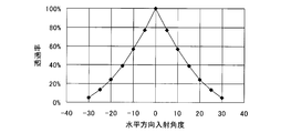
- FIG. 16 is a diagram showing the light utilization efficiency of the light reflecting optical element 2 in which the thicknesses of the two mirror sheets 21 and 22 are constant. Specifically, it is a graph showing the horizontal angle dependence of the ratio (also referred to as transmittance) of light that is reflected once by the mirror sheets 21 and 22 and passes through the light reflecting optical element 2.
- FIG. 16 shows that when the light reflecting optical element 2 is used, if the line of sight is shifted from the design line-of-sight direction S to the left-right direction, the transmittance is drastically reduced. Indicates that it is not possible.
- FIG. 17 and 18 are diagrams showing the light use efficiency of the light reflecting optical element 4A in which the thicknesses of the mirror sheets 41A and 42A are changed stepwise instead of continuously.
- the mirror sheets 41A and 42A are formed by changing the thickness in three steps in a stepwise manner in the left-right direction and the front-rear direction.
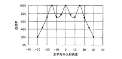
- FIG. 17 is a graph showing the horizontal angle dependency of the ratio (also referred to as transmittance) of light that is reflected once by each of the two mirror sheets 41A and 42A and passes through the light reflecting optical element 4A.
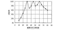
- These are graphs showing the vertical angle dependency of the ratio (also referred to as transmittance) of the light that is reflected once by each of the two mirror sheets 41A and 42A and passes through the light reflecting optical element 4A.
- the light reflecting optical element 4A is formed so that three maximum points with a transmittance of 100% appear within ⁇ 15 degrees in the left-right direction from the designed line-of-sight direction S. Therefore, even if the line of sight is shifted about ⁇ 15 degrees in the left-right direction from the design line-of-sight direction S, the brightness of the spatial image can be secured at least 70% in the left-right direction.
- the light reflecting optical element 4A is arranged so that three local maximum points with a transmittance of 100% appear within ⁇ 15 degrees in the front-rear direction from the designed line-of-sight direction S. Therefore, even if the line of sight is shifted about ⁇ 15 degrees in the front-rear direction from the designed line-of-sight direction S, the brightness of the spatial image can be secured at least 70% in the front-rear direction.
- FIG. 19 is a diagram showing how the light entering the light-reflecting optical element 4 slightly deviates from the designed line-of-sight direction S, and the traveling direction of the light before the vector OC enters the light-reflecting optical element 4.
- the traveling direction of the light after the vector CD is incident on the light reflecting optical element 4 is shown.
- the incident angle of light incident on the light reflecting optical element 4 is ⁇ (specifically, the angle between the normal line m of the reference plane L and the straight line OC), and the outgoing angle is Z (specifically, the normal line of the reference plane L).
- 20 is a top view including the reference plane L in FIG. 19, a side view including the straight line AA ′ and the normal m, and a plan view including the straight line OC and the straight line BB ′.
- a line of sight OC slightly deviated from the design line of sight direction S is considered.
- the point C is an intersection of the reference plane L and the line of sight
- the straight line AA ′ is a line in the design line of sight direction
- the straight line BB ′ is a line in a direction orthogonal to the line AA ′. That is, the straight line AA ′ and the straight line BB ′ intersect the light reflecting surfaces 43 of the two mirror sheets 41 and 42 constituting the light reflecting optical element 4 at an angle of 45 degrees.
- an angle at which the plane including the straight line BB ′ and the normal line m intersects with the plane including the line of sight OC and the straight line BB ′ is ⁇
- the plane including the straight line AA ′ and the normal line m, the line of sight OC and the normal line m is W.
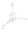
- the height of the rectangular parallelepiped formed by the straight line df and the straight line de is set to 1, the plane intersecting the x axis and the y axis at 45 degrees and orthogonal to the xy plane is defined as the light reflecting surface 43. .
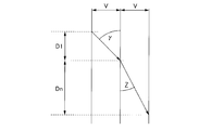
- the desired z-axis height D1 is: At the time. That is, if the light df incident on the upper end of the light reflecting surface 43 passing through the origin h is reflected on the lower end of the light reflecting surface 43 passing through f, all the light incident at the incident angle ⁇ is in the first layer. It is reflected once at the light reflecting surface 43. Therefore, when the height of the light reflecting surface 43 when the refractive index is 1 is D1, Therefore, Next, consider a case where light enters from a medium having a refractive index of 1 into a medium having a refractive index of n. FIG.
- tan ⁇ is a combined vector of tan ⁇ and tan ⁇ as shown in FIG.
- Expression (4) is established by substituting Expression (7) and Expression (8) into Expression (3).
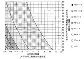
- FIG. 24 is a graph showing the horizontal and vertical thickness distribution of the mirror sheet 41 calculated based on the formula (4)
- FIG. 25 is a horizontal direction of the mirror sheet 42 calculated based on the formula (4). It is a graph which shows thickness distribution of a perpendicular direction.
- the thickness of the mirror sheet 41 is thin from the left direction toward the right direction. And is formed so as to become thinner from the near side toward the far side.
- the thickness of the mirror sheet 42 is from the right direction to the left direction. It is formed so as to become thinner and thinner from the near side toward the far side.
- the design is directed from the left back direction to the right front direction with respect to the design line-of-sight direction S.
- the thickness of the mirror sheet 41 on which the first light reflecting surface 43 is disposed is formed so as to be gradually reduced from the left direction to the right direction, and to the right rear with respect to the design line-of-sight direction S.
- the thickness of the mirror sheet 42 on which the second light reflecting surface 43 is arranged from the direction toward the left front direction is formed so as to gradually become thinner from the right direction toward the left direction, the design line of sight Even if the line of sight is shifted in the left-right direction from the direction S, the brightness of the spatial image can be ensured.
- the first light reflecting surface 43 is arranged from the left rear direction toward the right front direction with respect to the design line-of-sight direction S.
- the thickness of the mirror sheet 41 and the thickness of the mirror sheet 42 on which the second light reflecting surface 43 is arranged from the right back direction toward the left front direction with respect to the designed line-of-sight direction S are Since it is formed so as to gradually become thinner from the front direction toward the back direction, the brightness of the spatial image can be ensured even if the line of sight is shifted from the designed line-of-sight direction S to the front-rear direction.
Landscapes
- Physics & Mathematics (AREA)
- General Physics & Mathematics (AREA)
- Optics & Photonics (AREA)
- Optical Elements Other Than Lenses (AREA)
Abstract
実体部からの表示光を観察者に向けて反射する光反射光学素子を備えた空間映像表示装置であって、光反射光学素子は、長手方向に1つの光反射面を有する長手部材をその光反射面が同一方向側となるように複数配列した第1集合体及び第2集合体を、その光反射面が直交するように重ね合わせて構成され、実体部からの光を第1集合体及び第2光集合体の光反射面にそれぞれ1回ずつ反射させて実像を結像させ、第1集合体の光反射面が観察者の視線方向から見て左奥から右手前に向かって斜めに配列され、かつ第2集合体の光反射面が観察者の視線方向から見て右奥から左手前に向かって斜めに配列されている場合には、第1集合体の厚みは、観察者の視線方向から見て左方向から右方向に向かって薄くなり、第2集合体の厚みは、観察者の視線方向から見て右方向から左方向に向かって薄くなるように形成される。
Description
本発明は、空間中に映像を表示する空間映像表示装置に関する。
従来、リアルな3次元空中映像を実現するために、様々な光学素子が開発されている。例えば、特許文献1には、反射型面対称結像素子を用いてその素子の一方側に置かれた被投影物である物体の像を素子の反対側の面対象となる位置に結像させる空間映像表示装置が開示されている。この空間映像表示装置で用いられる反射型面対称結像素子は、所定の基盤を厚み方向に貫通させた複数の穴を備え、各穴の内壁に直交する2つの鏡面要素から構成される単位光学素子を形成したものであって、その穴を通じて基盤の一方の面方向から他方の面方向へ光が透過する際に、2つの鏡面要素でそれぞれ1回ずつ反射させるものである。被投影物から発せられた光は反射型面対称結像素子の単位光学素子を通過する際に2つの鏡面要素の一方で反射した後、鏡面で反射して反射光となり、その反射光が更に単位光学素子の2つの鏡面要素の他方で反射して、被投影物を仮想鏡に映した位置に結像することになる。
しかしながら、上記の光学素子には非常に微細な加工技術が要求されるため、このような光学素子を用いた空間映像表示装置では製造コストがかかるという問題がある。そこで、本出願人は、製造コストがかからない反射型面対称結像素子を特許文献2において提案している。
図1~図3は、特許文献2で提案された反射型面対称結像素子(以下、光反射光学素子という)の構成を示す図である。図1は光反射光学素子の外観図、図2は光反射光学素子を構成する直方体材の外観図、図3は光反射光学素子を形成する2つのミラーシートの組合せを示す外観図である。
光反射光学素子2は、図1及び図3に示すように、各々が多数の棒状の直方体材20を並列に密着させることにより形成された2つのミラーシート21、22を有する。
直方体材20は、図2に示すように、長手部材であり、長手方向に垂直な方向、すなわち、短手方向の四角形の断面の一辺が数百μmないし数cm前後の透明なアクリルに代表されるプラスチックまたはガラスの棒からなる。長さは投影する画像の大きさによって変化するが、数十mm~数m程度である。なお、長手方向に伸長した4面のうちの3面は光の透過または反射に使用する面であるため、滑らかな状態とする。直方体材20はミラーシート21、22各々で100本~20000本程度用いられる。
図2に示すように、直方体材20の長手方向に伸長した1面には光反射膜23が形成され、それにより光反射面となっている。光反射膜23はアルミや銀の蒸着あるいはスパッタなどによって形成される。
このような複数の直方体材20について、1つの直方体材20の光反射膜23を形成した面とは反対側の対向面24と別の直方体材20の光反射面23を密着させてミラーシート21、22が形成される。ミラーシート21、22は、図3に示すように、直方体材20の並列方向が交差するようにいずれか一方を90度回転させた状態で貼り合わせられ、それによって、光反射光学素子2が形成される。ミラーシート21の各直方体材20とミラーシート22の各直方体材20とが交差する部分が微小ミラーユニット(単位光学素子)を構成し、各微小ミラーユニットのミラーシート21の光反射面23が第1光反射面となり、ミラーシート22の光反射面23が第2光反射面となる。
かかる光反射光学素子2を用いた空間映像表示装置においては、図4に示すように、物体1が光反射光学素子2の一方の面側に配置され、光反射光学素子2には物体1からの光が斜めに入射するようになっている。光反射光学素子2の他方の面側には観察者の目Eが位置し、光反射光学素子2について物体1と面対称となる空間位置に実像3、すなわち空間映像が形成される。なお、図4における光反射光学素子2の両端部である下端A、上端A’は、図1の光反射光学素子2の対向角A、A’に対応している。より詳しくは、図5に示すように、物体1からの光は矢印Y1の方向でミラーシート22の光反射面23(第2光反射面)に反射し、その反射光は矢印Y2の方向でミラーシート21の光反射面23(第1光反射面)に反射し、その反射光は矢印Y3の方向で観察者に向けて進むので、光反射光学素子2の各光反射面23でそれぞれ1回、つまり2回反射して鏡映像を作り出すようになっている。
しかしながら、特許文献2に示す空間映像表示装置においては、設計上の視線方向から左右方向(図1に示す左右方向。図4における紙面に垂直な方向)に視線をずらしていくと、ミラーシート21、22各々において、反射せずに透過する光及び2回以上反射する光が増加してしまう、すなわち、ミラーシート21、22各々において、1回だけ反射する光が減少してしまい、結果的には、空間映像の明るさが左右方向によって異なってしまうという問題があった。
本発明は上記の事情を鑑みてなされたものであり、その課題の一例としては、設計上の視線方向から左右方向に視線をずらしても、空間映像の輝度を確保することができる空間映像表示装置を提供することにある。
上記の課題を達成するため、本発明の一態様は、実体部からの光を観察者に向けて反射する光反射光学素子を備えた空間映像表示装置であって、前記光反射光学素子は、1つの光反射面を有する長手部材をその光反射面が同一方向側となるように複数配列した第1集合体及び第2集合体を、その光反射面が直交するように重ね合わせて構成され、 前記第1集合体及び前記第2集合体を構成する複数の前記長手部材各々は、長手方向に伸長した4つの面を有する透光の直方体からなり、前記4つの面のうちの1面が前記光反射面であり、前記第1集合体及び前記第2集合体各々において、1つの前記直方体の前記光反射面と、隣接する前記直方体の前記光反射面と対向する面が当接するように前記直方体は配列され、前記実体部からの光を、前記第1集合体及び前記第2光集合体の前記光反射面にそれぞれ1回ずつ反射させて実像を結像させ、前記第1集合体の前記光反射面が、前記観察者の視線方向から見て左奥方向から右手前方向に向かって斜めに配列されているとともに、前記第2集合体の前記光反射面が、前記観察者の視線方向から見て右奥方向から左手前方向に向かって斜めに配列されている場合には、前記第1集合体の前記光反射面の短手方向の長さである前記第1集合体の厚みは、前記観察者の視線方向から見て左方向から右方向に向かって薄くなるように形成されているとともに、前記第2集合体の前記光反射面の短手方向の長さである前記第2集合体の厚みは、前記観察者の視線方向から見て右方向から左方向に向かって薄くなるように形成されている。
以下、本発明の実施の形態を図面を用いて説明する。
図6は、本発明の実施の形態に係る光反射光学素子4の外観斜視図である。本実施の形態に係る光反射光学素子4は、上述の図1~図3に示したように形成される(但し、図1~図3に示した符号2を符号4に、符号20を符号40に、符号21を符号41に、符号22を符号42、符号23を符号43に、符号24を符号44に置き換える)。すなわち、複数の直方体材40について、1つの直方体材40の光反射膜43を形成した面とは反対側の対向面44と別の直方体材20の光反射面43を密着させることにより、2つのミラーシート41、42を形成するとともに、この2つのミラーシート41、42を、直方体材40の並列方向が交差するようにいずれか一方を90度回転させた状態で貼り合わせて、光反射光学素子4を形成する。なお、図6は、上記方法で形成された光反射光学素子4を、図1の左右方向及び前後方向に平行な面で切断した場合(図1の点線Pで切断した場合)の形状を示している。ここで、図1で示した前後左右の方向及びAA’の方向は、図6に示した前後左右の方向及びAA’の方向と同一である。詳しくは、本実施の形態では、ミラーシート41、42の貼り合わせ面(以下、基準面ともいう)Lにおける前後方向をAA’方向、左右方向をBB’方向と定義する。また、ミラーシート41を第1ミラーシート、ミラーシート42を第2ミラーシートとも称し、ミラーシート41の光反射面43を第1光反射面、ミラーシート42の光反射面43を第2光反射面とも称する。
ここで、図7~図10を用いて、光反射光学素子4の特徴について説明する。図7は、ミラーシート41の外観斜視図、図8は、ミラーシート41の上面図、側面図及び前面図であり、図9は、ミラーシート42の外観斜視図、図10は、ミラーシート42の上面図、側面図及び前面図である。なお、本実施の形態でいう設計上の視線方向Sとは、図7~図10に示すように、基準面LのAA’方向(AからA’に向けて、つまり手前から奥に向けて見た方向)を斜め上から見た方向をいう。本実施の形態では、ミラーシート41のそれぞれの第1光反射面43は、AA’方向及びBB’方向と45度で交差するように配置され、また、ミラーシート42のそれぞれの第2光反射面43は、第1光反射面43の配列方向と直交するとともに、AA’方向及びBB’方向と45度で交差して配置されている。すなわち、本実施の形態では、ミラーシート41の第1光反射面43は、それぞれが平行となるように左奥方向から右手前方向に配置され、また、ミラーシート42の第2光反射面43は、それぞれが平行となるように右奥方向から左手前方向に配置される。また、ミラーシート41及び42を構成するそれぞれの光反射面43の長手方向が光反射面43の配列方向であり、ミラーシート41及び42を構成するそれぞれの光反射面43の短手方向が光反射面43の高さ(厚み)となっている。
光反射光学素子4は光反射光学素子2と異なり、2つのミラーシート41及び42の厚さは均一でないことを特徴としている。すなわち、左奥方向から右手前方向に向かって第1光反射面43が配置されているミラーシート41の厚みは、図7及び図8に示すように、左方向から右方向に向かって薄くなるように、かつ、手前方向から奥方向に向かって薄くなるように形成されている。一方、右奥方向から左手前方向に向かって第2光反射面43が配置されているミラーシート42の厚みは、図9及び図10に示すように、右方向から左方向に向かって薄くなるように、かつ、手前方向から奥方向に向かって薄くなるように形成されている。
なお、光反射光学素子4のミラーシート41、42の厚みは、左右方向及び前後方向に対して連続的に変化しているが、正確には、図6~図10に示したように直線的に変化するのではなく、後述する光反射光学素子4の厚みに関する式(4)に基づいて曲線的に変化している。なお、光反射光学素子4の作製にあたっては、種々の方法考えられる。一例としては、最厚部の厚さでミラーシート41、42を作成し、その後、ミラーシート41、42の両表面を研磨して徐々に薄くしていくことにより所望の厚みを得るようにしてもよい。
図11から図13を用いて、光反射光学素子4を用いた空間映像表示装置の作用について説明する。
図11に示すように、観察者Eからの視線は、空間映像3の延長上にある光反射光学素子4の中央部及び周辺部に入射し、光反射光学素子4によって屈曲され、空間映像3の光反射光学素子4に対する面対称位置にある実体部(ディスプレイ部)1に至る。この場合、光反射光学素子4を構成するミラーシート41、42それぞれの光反射面43の前後方向と左右方向の厚みは、図6~図10に示す構成となっているので、視線方向の光はミラーシート41、42においてそれぞれ1回だけ反射する光が増加する一方、反射せずに透過する光及び2回以上反射する光は減少することとなる。これにより、観察者Eから観察される空間映像3の輝度分布は実体部1の輝度分布に近くなる。
図12は、光反射光学素子4を用いた空間映像表示装置において、実体1からの光が左右方向の光に分かれて光反射光学素子4において2回反射して実像3を形成する状態を、前面(B-B’断面)、側面(A-A’断面)及び上面から見た図である。また、図13は、光反射光学素子4を用いた空間映像表示装置において、実体1からの光が前後方向の光に分かれて光反射光学素子4において2回反射して実像3を形成する状態を、前面(B-B’断面)、側面(A-A’断面)及び上面から見た図である。
実体1から出射した光は光反射光学素子4の第1層目であるミラーシート42の光反射面43によって反射され、第1層目のミラーシート42とは90度直交して配置されている第2層目のミラーシート41の光反射面43によって再び反射され、実体1とは基準面Lを面対称とする位置に実像3を形成する。
詳しくは、図12に示すように、設計上の視線方向Sよりも左方向に出射した光L1は、設計上の視線方向Sに出射した光L2と比べて、光線とミラーシート42の光反射面43とのなす角度が大きくなるので、設計上の視線方向Sに出射した光L2と比べて、ミラーシート42内に深く入り込むことはできない。したがって、設計上の視線方向Sから左方向に対しては、ミラーシート42の厚さは徐々に薄くしていく必要がある。一方、設計上の視線方向Sよりも右方向に出射した光L3は、設計上の視線方向Sに出射した光L2と比べて、光線とミラーシート42の光反射面43とのなす角度が小さくなるので、設計上の視線方向Sに出射した光L2と比べて、ミラーシート42内に深く入り込むことができる。したがって、設計上の視線方向Sから右方向に対しては、ミラーシート42の厚さは徐々に厚くしていく必要がある。以上から、本実施の形態では、右奥方向から左手前方向に向かって光反射面43が配置されているミラーシート42に対しては、右方向から左方向に向かってミラーシート42の厚さは徐々に薄くなるように形成されている。
また、図13に示すように、設計上の視線方向Sよりも奥方向に出射した光L4は、設計上の視線方向Sに出射した光L5と比べて、光線とミラーシート42の光反射面43とのなす角度が大きくなるので、設計上の視線方向Sに出射した光L5と比べて、ミラーシート42内に深く入り込むことはできない。したがって、設計上の視線方向Sから奥方向に対しては、ミラーシート42の厚さは徐々に薄くしていく必要がある。一方、設計上の視線方向Sよりも手前方向に出射した光L6は、設計上の視線方向Sに出射した光L5と比べて、光線とミラーシート42の光反射面43とのなす角度が小さくなるので、設計上の視線方向Sに出射した光L5と比べて、ミラーシート42内に深く入り込むことができる。したがって、設計上の視線方向Sから手前方向に対しては、ミラーシート42の厚さは徐々に厚くしていく必要がある。以上から、本実施の形態では、右奥方向から左手前方向に向かって光反射面43が配置されているミラーシート42に対しては、手前方向から奥方向に向かってミラーシート42の厚さは徐々に薄くなるように形成されている。
なお、上記では図12及び図13を参照しつつ、ミラーシート42の厚さについて詳述したが、ミラーシート41の厚さについても同様である。すなわち、光線とミラーシート41の光反射面43とのなす角度が大きくなると、ミラーシート41内に深く入り込むことはできないので、左奥方向から右手前方向に向かって光反射面43が配置されているミラーシート41に対しては、左方向から右方向に向かってミラーシート41の厚さは徐々に薄くなるとともに、手前方向から奥方向に向かってミラーシート41の厚さは徐々に薄くなるように形成されている。
この結果、本実施の形態の光反射光学素子4を用いた空間映像表示装置においては、観察者は設計上の視線方向Sに対して左右方向に視線をずらしても、空間映像を均一な明るさで視認することができる。また、観察者は設計上の視線方向Sに対して前後方向に視線をずらしても、空間映像を均一な明るさで視認することができる。
なお、本実施の形態では、ミラーシート41を上、ミラーシート42を下として上下に貼り合わせたが、上述したように、ミラーシートの厚さは、光線とミラーシートの光反射面43とのなす角度に応じて決まるものであるから、上下を逆にして貼り合わせてもよい。すなわち、ミラーシート42を上、ミラーシート41を下として貼り合わせてもよく、この場合にも、同様の作用を示すこととなる。
図14及び図15は、本実施の形態の光反射光学素子4(正確には後述する式(4)に基づいて厚さが算出されたミラーシート41、42からなる光反射光学素子4)の光の利用効率を示す図である。図14は、ミラーシート41、42においてそれぞれ1回ずつ反射して、光反射光学素子4を透過する光の比率(透過率ともいう)の水平角度依存性を示すグラフであり、図15は、ミラーシート41、42においてそれぞれ1回ずつ反射して、光反射光学素子4を透過する光の比率(透過率ともいう)の垂直角度依存性を示すグラフである。
図14のグラフにおいて、水平方向の入射角度0度は、設計上の視線方向Sを意味しているので、図14は、設計上の視線方向Sから左右方向に±15度程度、視線をずらしても、透過率はほぼ100%で変化なく、空間映像の輝度が確保されていることを示している。
また、図15のグラフにおいて、垂直方向の入射角度45度は、設計上の視線方向Sを意味しているので、図15は、設計上の視線方向Sから前後方向に±15度程度視線をずらしても、透過率はほぼ100%で変化なく、空間映像の輝度が確保されていることを示している。
これに対して、図16は、2つのミラーシート21、22の厚さが一定な光反射光学素子2の光の利用効率を示す図である。詳しくは、ミラーシート21、22においてそれぞれ1回ずつ反射して、光反射光学素子2を透過する光の比率(透過率ともいう)の水平角度依存性を示すグラフである。図16は、光反射光学素子2を用いる場合には、設計上の視線方向Sから左右方向に視線をずらすと、透過率は激減するので、左右方向に対しては空間映像の明るさを確保できないことを示している。
図17及び図18は、連続的ではなく段階的にミラーシート41A、42Aの厚さを変化させた光反射光学素子4Aの光の利用効率を示す図である。ミラーシート41A、42Aは、具体的には、左右方向及び前後方向に対して、階段状に3段階厚さを変化して形成されている。図17は、2つのミラーシート41A、42Aにおいてそれぞれ1回ずつ反射して、光反射光学素子4Aを透過する光の比率(透過率ともいう)の水平角度依存性を示すグラフであり、図18は、2つのミラーシート41A、42Aにおいてそれぞれ1回ずつ反射して、光反射光学素子4Aを透過する光の比率(透過率ともいう)の垂直角度依存性を示すグラフである。
この場合には、図17に示すように、設計上の視線方向Sから左右方向に±15度以内に透過率が100%となる極大点が3つ現れるように光反射光学素子4Aを形成しているので、設計上の視線方向Sから左右方向に±15度程度視線をずらしても、左右方向に対しては空間映像の明るさを少なくとも70%以上確保することができる。
また、この場合には、図18に示すように、設計上の視線方向Sから前後方向に±15度以内に透過率が100%となる極大点が3つ現れるように光反射光学素子4Aを形成しているので、設計上の視線方向Sから前後方向に±15度程度視線をずらしても、前後方向に対しては空間映像の明るさを少なくとも70%以上確保することができる。
次に、図19及び図20を用いて、光反射光学素子4のミラーシート41及び42の厚さDについて詳しく説明する。図19は、設計上の視線方向Sからやや外れて光反射光学素子4に入射する光の進み方を示す図であり、ベクトルOCが光反射光学素子4に入射する前の光の進行方向、ベクトルCDが光反射光学素子4に入射した後の光の進行方向を示している。ここで、光反射光学素子4に入射する光の入射角をγ(詳しくは、基準面Lの法線mと直線OCとなす角度)、出射角をZ(詳しくは、基準面Lの法線mと直線ODとなす角度)とする。また、図20は、図19の基準面Lを含む上面図、直線AA'と法線mを含む側面図、及び直線OCと直線BB’を含む平面図である。
図19及び図20に示すように、設計上の視線方向Sからややはずれた視線OCを使って考える。点Cは、基準面Lと視線の交点であり、直線AA'は、設計上の視線方向の線、直線BB'は、直線AA’に直交する方向の線である。すなわち、直線AA'及び直線BB’は光反射光学素子4を構成する2つのミラーシート41及び42の光反射面43とそれぞれ45度の角度で交差している。このとき、直線BB’と法線mを含む平面と、視線OCと直線BB’を含む平面が交わる角度をαとし、直線AA'と法線mを含む平面と、視線OCと法線mを含む平面が交わる角度をβとする。また、光反射光学素子4内の屈折率をn、光反射光学素子4を構成するミラーシート41、42における光反射面43同士のミラー間隔をWとする。
すると、


となり、式(1)~(3)から、

が導かれる。
ここで、式(1)~(3)の成立について詳しく説明する。
まず、式(3)に関しては、図21の座標系で考える。まず、屈折率n=1の媒体内を進行する光を直線dfで示す。このとき、直線dfとz軸とのなす角度はγ、直線dfをxz平面に射影した直線deとz軸とのなす角度をα、直線dfと直線deのなす角度をβとする(図21のα、β、γは、図19及び図20のα、β、γに対応している)。また、直線df及び直線deで作られる直方体のz軸方向の高さを1とおき、x軸及びy軸とそれぞれ45度で交わり、かつ、xy平面と直交する平面を光反射面43とする。
直角三角形aedにおいて、ad=tanαから、de=1/cosαとなる。一方、直角三角形defにおいて、ef=de×tanβより、ef=tanβ/cosαとなる。
したがって、頂点fを通る光反射面43において、光反射面43とx軸との交点をPとすると、OP=he+eP=tanα+tanβ/cosαとなる。
今、光反射面43間の間隔をWとすると、求めたいz軸高さD1は、

のときである。すなわち、原点hを通る光反射面43の上端を入射してきた光dfがfを通る光反射面43の下端に反射されるのであれば、入射角γで入射した光はすべて第1層目の光反射面43において1回反射されることとなる。したがって、屈折率1のときの光反射面43の高さをD1とすると、

よって、

次に、屈折率1の媒体から屈折率nの媒体に光が進入する場合を考える。図22は、図21において直線df及びz軸を含む平面Q上の光の進み方を示している。ここで、平面Q上における光反射面43の間隔をV、屈折率nのときの光反射面43の高さをDnとして、屈折率1の媒体から屈折率nの媒体に光が進入する場合のhf方向に対するz軸方向の距離を考えると、tanγ=V/D1、tanZ=V/Dnであるから、

この結果、式(5)及び式(6)より、式(3)は成立する。
次に、式(1)に関しては、光の進む距離を考えると、tanγは、図23に示すように、tanαとtanβの合成ベクトルであるから、式(1)が成立する。
また、式(2)に関しては、スネルの法則から、1・sinγ=n・sinZであるから、

が成り立つ。また、式(1)からは、

であるから、式(7)のγに式(8)を代入すると、式(2)は成立する。
最後に、式(4)に関しては、式(3)に式(7)及び式(8)を代入すると、式(4)が成立する。
なお、式(3)においてβ=0のとき、すなわち、設計上の視線方向Sから見た場合(γ=α、Z=Xのとき)には、

であり、スネルの法則から、

となる。なお、式(9)及び(10)は、特許文献2にて本出願人がすでに開示している式である。
図24は、式(4)に基づいて算出されたミラーシート41の水平方向及び垂直方向の厚み分布を示すグラフ、図25は、式(4)に基づいて算出されたミラーシート42の水平方向及び垂直方向の厚み分布を示すグラフである。図24に示すように、左奥方向から右手前方向に向かって第1光反射面43が配置されているミラーシート41においては、ミラーシート41の厚みは、左方向から右方向に向かって薄くなるように、かつ、手前方向から奥方向に向かって薄くなるように形成されている。一方、図25に示すように、右奥方向から左手前方向に向かって第2光反射面43が配置されているミラーシート42においては、ミラーシート42の厚みは、右方向から左方向に向かって薄くなるように、かつ、手前方向から奥方向に向かって薄くなるように形成されている。
以上から、本実施の形態によれば、光反射光学素子4を構成する第1ミラーシート41及び第2ミラーシート42において、設計上の視線方向Sに対して左奥方向から右手前方向に向かって第1光反射面43が配置されているミラーシート41の厚さは、左方向から右方向に向かって徐々に薄くなるように形成されるとともに、設計上の視線方向Sに対して右奥方向から左手前方向に向かって第2光反射面43が配置されているミラーシート42の厚さは、右方向から左方向に向かって徐々に薄くなるように形成されるので、設計上の視線方向Sから左右方向に視線をずらしても、空間映像の輝度を確保することができる。
また、光反射光学素子4を構成する第1ミラーシート41及び第2ミラーシート42において、設計上の視線方向Sに対して左奥方向から右手前方向に向かって第1光反射面43が配置されているミラーシート41の厚さ、及び設計上の視線方向Sに対して右奥方向から左手前方向に向かって第2光反射面43が配置されているミラーシート42の厚さは、いずれも手前方向から奥方向に向かって徐々に薄くなるように形成されるので、設計上の視線方向Sから前後方向に視線をずらしても、空間映像の輝度を確保することができる。
以上、本発明の実施の形態について説明してきたが、本発明は、上述した実施の形態に限られるものではなく、本発明の要旨を逸脱しない範囲において、本発明の実施の形態に対して種々の変形や変更を施すことができ、そのような変形や変更を伴うものもまた、本発明の技術的範囲に含まれるものである。
1 実体部(物体、ディスプレイ部)
2,4,4A 光反射光学素子(ミラー)
3 実像(空間映像)
20,40 直方体材
21,22,41,42,41A,42A ミラーシート
23,43 光反射面
2,4,4A 光反射光学素子(ミラー)
3 実像(空間映像)
20,40 直方体材
21,22,41,42,41A,42A ミラーシート
23,43 光反射面
Claims (5)
- 実体部からの光を観察者に向けて反射する光反射光学素子を備えた空間映像表示装置であって、
前記光反射光学素子は、
1つの光反射面を有する長手部材をその光反射面が同一方向側となるように複数配列した第1集合体及び第2集合体を、その光反射面が直交するように重ね合わせて構成され、
前記第1集合体及び前記第2集合体を構成する複数の前記長手部材各々は、長手方向に伸長した4つの面を有する透光の直方体からなり、前記4つの面のうちの1面が前記光反射面であり、
前記第1集合体及び前記第2集合体各々において、1つの前記直方体の前記光反射面と、隣接する前記直方体の前記光反射面と対向する面が当接するように前記直方体は配列され、
前記実体部からの光を、前記第1集合体及び前記第2光集合体の前記光反射面にそれぞれ1回ずつ反射させて実像を結像させ、
前記第1集合体の前記光反射面が、前記観察者の視線方向から見て左奥方向から右手前方向に向かって斜めに配列されているとともに、前記第2集合体の前記光反射面が、前記観察者の視線方向から見て右奥方向から左手前方向に向かって斜めに配列されている場合には、
前記第1集合体の前記光反射面の短手方向の長さである前記第1集合体の厚みは、前記観察者の視線方向から見て左方向から右方向に向かって薄くなるように形成されているとともに、前記第2集合体の前記光反射面の短手方向の長さである前記第2集合体の厚みは、前記観察者の視線方向から見て右方向から左方向に向かって薄くなるように形成されている空間映像表示装置。 - 前記第1集合体の前記光反射面が、前記観察者の視線方向から見て左奥方向から右手前方向に向かって斜めに配列されているとともに、前記第2集合体の前記光反射面が、前記観察者の視線方向から見て右奥方向から左手前方向に向かって斜めに配列されている場合には、
前記第1集合体及び前記第2集合体の厚みは、いずれも、前記観察者の視線方向から見て奥方向から手前方向に向かって薄くなるように形成されている請求項1記載の空間映像表示装置。 - 前記第1集合体及び前記第2集合体の厚みは、前記観察者の視線方向から見て前後左右方向に連続的に変化するように形成されている請求項2記載の空間映像表示装置。
- 前記第1集合体及び前記第2集合体の厚みは、前記観察者の視線方向から見て前後左右方向に所定回数に亘って階段状に変化するように形成されている請求項2記載の空間映像表示装置。
- 前記第1集合体と前記第2集合体を重ね合わせるときの貼り付け面を基準面Lとし、前記観察者の視線位置をO、前記観察者の視線方向と基準面Lとの交点をC、基準面Lにおいて前記第1集合体及び前記第2集合体の前記光反射面各々と45度で交わる一直線をAA’、 基準面Lにおいて直線AA’に直交する直線をBB’とし、直線BB’と基準面Lの法線mを含む平面と、視線OCと直線BB’を含む平面のなす角度をαとし、直線AA'と法線mを含む平面と、視線OCと法線mを含む平面のなす角度をβとし、前記光反射光学素子の光学屈折率をn、前記第1集合体及び前記第2集合体における前記光反射面同士の間隔をWとすると、前記第1集合体及び前記第2集合体それぞれの厚みDは、

Priority Applications (2)
| Application Number | Priority Date | Filing Date | Title |
|---|---|---|---|
| PCT/JP2010/067438 WO2012046296A1 (ja) | 2010-10-05 | 2010-10-05 | 空間映像表示装置 |
| JP2012537505A JP5367912B2 (ja) | 2010-10-05 | 2010-10-05 | 空間映像表示装置 |
Applications Claiming Priority (1)
| Application Number | Priority Date | Filing Date | Title |
|---|---|---|---|
| PCT/JP2010/067438 WO2012046296A1 (ja) | 2010-10-05 | 2010-10-05 | 空間映像表示装置 |
Publications (1)
| Publication Number | Publication Date |
|---|---|
| WO2012046296A1 true WO2012046296A1 (ja) | 2012-04-12 |
Family
ID=45927316
Family Applications (1)
| Application Number | Title | Priority Date | Filing Date |
|---|---|---|---|
| PCT/JP2010/067438 Ceased WO2012046296A1 (ja) | 2010-10-05 | 2010-10-05 | 空間映像表示装置 |
Country Status (2)
| Country | Link |
|---|---|
| JP (1) | JP5367912B2 (ja) |
| WO (1) | WO2012046296A1 (ja) |
Cited By (3)
| Publication number | Priority date | Publication date | Assignee | Title |
|---|---|---|---|---|
| JP2016133577A (ja) * | 2015-01-17 | 2016-07-25 | 有限会社オプトセラミックス | 空中結像装置 |
| JP2017138411A (ja) * | 2016-02-02 | 2017-08-10 | 大日本印刷株式会社 | 空間浮遊映像表示光学シート、空間浮遊映像表示装置 |
| CN113519059A (zh) * | 2019-05-09 | 2021-10-19 | 虹软科技股份有限公司 | 图像传感器封装 |
Citations (2)
| Publication number | Priority date | Publication date | Assignee | Title |
|---|---|---|---|---|
| WO2009136578A1 (ja) * | 2008-05-09 | 2009-11-12 | パイオニア株式会社 | 空間映像表示装置 |
| JP2009276699A (ja) * | 2008-05-16 | 2009-11-26 | National Institute Of Information & Communication Technology | 2面コーナーリフレクタアレイ |
-
2010
- 2010-10-05 WO PCT/JP2010/067438 patent/WO2012046296A1/ja not_active Ceased
- 2010-10-05 JP JP2012537505A patent/JP5367912B2/ja active Active
Patent Citations (2)
| Publication number | Priority date | Publication date | Assignee | Title |
|---|---|---|---|---|
| WO2009136578A1 (ja) * | 2008-05-09 | 2009-11-12 | パイオニア株式会社 | 空間映像表示装置 |
| JP2009276699A (ja) * | 2008-05-16 | 2009-11-26 | National Institute Of Information & Communication Technology | 2面コーナーリフレクタアレイ |
Non-Patent Citations (1)
| Title |
|---|
| HIROKAZU HASHIMOTO: "A study of Real-image-projector by using the Transmissive-retro-reflectors", ITE TECHNICAL REPORT, vol. 34, no. 12, 2 March 2010 (2010-03-02), pages 9 - 11 * |
Cited By (4)
| Publication number | Priority date | Publication date | Assignee | Title |
|---|---|---|---|---|
| JP2016133577A (ja) * | 2015-01-17 | 2016-07-25 | 有限会社オプトセラミックス | 空中結像装置 |
| JP2017138411A (ja) * | 2016-02-02 | 2017-08-10 | 大日本印刷株式会社 | 空間浮遊映像表示光学シート、空間浮遊映像表示装置 |
| CN113519059A (zh) * | 2019-05-09 | 2021-10-19 | 虹软科技股份有限公司 | 图像传感器封装 |
| CN113519059B (zh) * | 2019-05-09 | 2024-04-02 | 虹软科技股份有限公司 | 图像传感器封装 |
Also Published As
| Publication number | Publication date |
|---|---|
| JP5367912B2 (ja) | 2013-12-11 |
| JPWO2012046296A1 (ja) | 2014-02-24 |
Similar Documents
| Publication | Publication Date | Title |
|---|---|---|
| JP7788167B2 (ja) | 二次元の拡張を有する導光光学素子を含む光学システム | |
| JP7437068B2 (ja) | 表示装置 | |
| CN111373297B (zh) | 基于二维光栅的平面光波导 | |
| CN106796348B (zh) | 导光装置及虚像显示设备 | |
| CN106291958B (zh) | 一种显示装置及图像显示方法 | |
| JP5352410B2 (ja) | 空間映像表示装置 | |
| JP2021047440A (ja) | 表示装置及び空中像の表示方法 | |
| CN102460269B (zh) | 显示装置 | |
| JP5063494B2 (ja) | 表示装置 | |
| JP2021507320A (ja) | マルチビーム素子ベースのニアアイディスプレイ、システム、および方法 | |
| JP5904437B2 (ja) | 空間映像表示装置 | |
| JP2020515884A (ja) | 拡張現実または仮想現実ディスプレイ用の導波路 | |
| US20180329208A1 (en) | Light guide and virtual image display device | |
| JP2011242729A (ja) | 表示装置 | |
| JP2009075483A (ja) | 体積走査型3次元空中映像ディスプレイ | |
| CN102804026A (zh) | 显示装置 | |
| CN110262051B (zh) | 一种基于方向性光源的逆反射立体显示装置 | |
| TW201248201A (en) | Microreplicated film for autostereoscopic displays | |
| JP2017003845A (ja) | 導光装置及び虚像表示装置 | |
| US20110235201A1 (en) | Two-image-point imaging optical device | |
| JP2009229905A (ja) | 3次元空中映像ディスプレイ装置 | |
| US20150346499A1 (en) | Three-dimensional display apparatus | |
| JP2019113721A (ja) | 導光装置及び表示装置 | |
| JP5367912B2 (ja) | 空間映像表示装置 | |
| WO2019111820A1 (ja) | 表示装置及びヘッドマウントディスプレイ |
Legal Events
| Date | Code | Title | Description |
|---|---|---|---|
| 121 | Ep: the epo has been informed by wipo that ep was designated in this application |
Ref document number: 10858104 Country of ref document: EP Kind code of ref document: A1 |
|
| ENP | Entry into the national phase |
Ref document number: 2012537505 Country of ref document: JP Kind code of ref document: A |
|
| NENP | Non-entry into the national phase |
Ref country code: DE |
|
| 122 | Ep: pct application non-entry in european phase |
Ref document number: 10858104 Country of ref document: EP Kind code of ref document: A1 |