WO2012043530A1 - Vehicle control device and vehicle control method - Google Patents
Vehicle control device and vehicle control method Download PDFInfo
- Publication number
- WO2012043530A1 WO2012043530A1 PCT/JP2011/071995 JP2011071995W WO2012043530A1 WO 2012043530 A1 WO2012043530 A1 WO 2012043530A1 JP 2011071995 W JP2011071995 W JP 2011071995W WO 2012043530 A1 WO2012043530 A1 WO 2012043530A1
- Authority
- WO
- WIPO (PCT)
- Prior art keywords
- engine
- vehicle
- stop
- restart
- time
- Prior art date
Links
Images


Classifications
-
- F—MECHANICAL ENGINEERING; LIGHTING; HEATING; WEAPONS; BLASTING
- F02—COMBUSTION ENGINES; HOT-GAS OR COMBUSTION-PRODUCT ENGINE PLANTS
- F02D—CONTROLLING COMBUSTION ENGINES
- F02D29/00—Controlling engines, such controlling being peculiar to the devices driven thereby, the devices being other than parts or accessories essential to engine operation, e.g. controlling of engines by signals external thereto
- F02D29/02—Controlling engines, such controlling being peculiar to the devices driven thereby, the devices being other than parts or accessories essential to engine operation, e.g. controlling of engines by signals external thereto peculiar to engines driving vehicles; peculiar to engines driving variable pitch propellers
-
- B—PERFORMING OPERATIONS; TRANSPORTING
- B60—VEHICLES IN GENERAL
- B60W—CONJOINT CONTROL OF VEHICLE SUB-UNITS OF DIFFERENT TYPE OR DIFFERENT FUNCTION; CONTROL SYSTEMS SPECIALLY ADAPTED FOR HYBRID VEHICLES; ROAD VEHICLE DRIVE CONTROL SYSTEMS FOR PURPOSES NOT RELATED TO THE CONTROL OF A PARTICULAR SUB-UNIT
- B60W10/00—Conjoint control of vehicle sub-units of different type or different function
- B60W10/04—Conjoint control of vehicle sub-units of different type or different function including control of propulsion units
- B60W10/06—Conjoint control of vehicle sub-units of different type or different function including control of propulsion units including control of combustion engines
-
- B—PERFORMING OPERATIONS; TRANSPORTING
- B60—VEHICLES IN GENERAL
- B60W—CONJOINT CONTROL OF VEHICLE SUB-UNITS OF DIFFERENT TYPE OR DIFFERENT FUNCTION; CONTROL SYSTEMS SPECIALLY ADAPTED FOR HYBRID VEHICLES; ROAD VEHICLE DRIVE CONTROL SYSTEMS FOR PURPOSES NOT RELATED TO THE CONTROL OF A PARTICULAR SUB-UNIT
- B60W30/00—Purposes of road vehicle drive control systems not related to the control of a particular sub-unit, e.g. of systems using conjoint control of vehicle sub-units, or advanced driver assistance systems for ensuring comfort, stability and safety or drive control systems for propelling or retarding the vehicle
- B60W30/18—Propelling the vehicle
- B60W30/18009—Propelling the vehicle related to particular drive situations
- B60W30/18109—Braking
- B60W30/18118—Hill holding
-
- F—MECHANICAL ENGINEERING; LIGHTING; HEATING; WEAPONS; BLASTING
- F02—COMBUSTION ENGINES; HOT-GAS OR COMBUSTION-PRODUCT ENGINE PLANTS
- F02N—STARTING OF COMBUSTION ENGINES; STARTING AIDS FOR SUCH ENGINES, NOT OTHERWISE PROVIDED FOR
- F02N11/00—Starting of engines by means of electric motors
- F02N11/08—Circuits or control means specially adapted for starting of engines
- F02N11/0814—Circuits or control means specially adapted for starting of engines comprising means for controlling automatic idle-start-stop
- F02N11/0818—Conditions for starting or stopping the engine or for deactivating the idle-start-stop mode
- F02N11/0833—Vehicle conditions
- F02N11/0837—Environmental conditions thereof, e.g. traffic, weather or road conditions
-
- B—PERFORMING OPERATIONS; TRANSPORTING
- B60—VEHICLES IN GENERAL
- B60W—CONJOINT CONTROL OF VEHICLE SUB-UNITS OF DIFFERENT TYPE OR DIFFERENT FUNCTION; CONTROL SYSTEMS SPECIALLY ADAPTED FOR HYBRID VEHICLES; ROAD VEHICLE DRIVE CONTROL SYSTEMS FOR PURPOSES NOT RELATED TO THE CONTROL OF A PARTICULAR SUB-UNIT
- B60W2540/00—Input parameters relating to occupants
- B60W2540/12—Brake pedal position
-
- B—PERFORMING OPERATIONS; TRANSPORTING
- B60—VEHICLES IN GENERAL
- B60W—CONJOINT CONTROL OF VEHICLE SUB-UNITS OF DIFFERENT TYPE OR DIFFERENT FUNCTION; CONTROL SYSTEMS SPECIALLY ADAPTED FOR HYBRID VEHICLES; ROAD VEHICLE DRIVE CONTROL SYSTEMS FOR PURPOSES NOT RELATED TO THE CONTROL OF A PARTICULAR SUB-UNIT
- B60W2552/00—Input parameters relating to infrastructure
- B60W2552/15—Road slope
-
- F—MECHANICAL ENGINEERING; LIGHTING; HEATING; WEAPONS; BLASTING
- F02—COMBUSTION ENGINES; HOT-GAS OR COMBUSTION-PRODUCT ENGINE PLANTS
- F02D—CONTROLLING COMBUSTION ENGINES
- F02D2200/00—Input parameters for engine control
- F02D2200/02—Input parameters for engine control the parameters being related to the engine
- F02D2200/06—Fuel or fuel supply system parameters
- F02D2200/0625—Fuel consumption, e.g. measured in fuel liters per 100 kms or miles per gallon
-
- F—MECHANICAL ENGINEERING; LIGHTING; HEATING; WEAPONS; BLASTING
- F02—COMBUSTION ENGINES; HOT-GAS OR COMBUSTION-PRODUCT ENGINE PLANTS
- F02N—STARTING OF COMBUSTION ENGINES; STARTING AIDS FOR SUCH ENGINES, NOT OTHERWISE PROVIDED FOR
- F02N11/00—Starting of engines by means of electric motors
- F02N11/10—Safety devices
-
- F—MECHANICAL ENGINEERING; LIGHTING; HEATING; WEAPONS; BLASTING
- F02—COMBUSTION ENGINES; HOT-GAS OR COMBUSTION-PRODUCT ENGINE PLANTS
- F02N—STARTING OF COMBUSTION ENGINES; STARTING AIDS FOR SUCH ENGINES, NOT OTHERWISE PROVIDED FOR
- F02N2200/00—Parameters used for control of starting apparatus
- F02N2200/12—Parameters used for control of starting apparatus said parameters being related to the vehicle exterior
- F02N2200/124—Information about road conditions, e.g. road inclination or surface
-
- Y—GENERAL TAGGING OF NEW TECHNOLOGICAL DEVELOPMENTS; GENERAL TAGGING OF CROSS-SECTIONAL TECHNOLOGIES SPANNING OVER SEVERAL SECTIONS OF THE IPC; TECHNICAL SUBJECTS COVERED BY FORMER USPC CROSS-REFERENCE ART COLLECTIONS [XRACs] AND DIGESTS
- Y02—TECHNOLOGIES OR APPLICATIONS FOR MITIGATION OR ADAPTATION AGAINST CLIMATE CHANGE
- Y02T—CLIMATE CHANGE MITIGATION TECHNOLOGIES RELATED TO TRANSPORTATION
- Y02T10/00—Road transport of goods or passengers
- Y02T10/10—Internal combustion engine [ICE] based vehicles
- Y02T10/40—Engine management systems
Definitions
- the present application relates to a vehicle control device and a vehicle control method for automatically stopping and automatically restarting an engine.
- the vehicle control device described in Patent Document 1 automatically stops the engine on condition that the brake depression amount is equal to or greater than the first threshold X, and automatically operates the engine on condition that the brake depression amount is equal to or smaller than the second threshold Y. To restart. Furthermore, the vehicle control device of Patent Document 1 is proposed to make the first threshold and the second threshold variable according to the vehicle speed.
- an AT car (automatic car) equipped with an automatic transmission with a torque converter generates a thrust in the forward direction of the vehicle due to a creep phenomenon even when the engine is idle.
- the creep phenomenon is a phenomenon in which, in an AT car, when the shift lever is in the traveling position, the vehicle advances slowly even without depressing the accelerator pedal. The creep phenomenon occurs because the torque converter transmits some power to the drive wheels even when the engine is idle.
- the object of the present application is to preferably avoid slipping of the vehicle at the time of stopping on a slope while avoiding unnecessary stopping of the engine which can not contribute to fuel saving as much as possible in a vehicle performing automatic stop and restart of the engine. It is providing a vehicle control device and a vehicle control method that can be prevented.
- the vehicle control device of the present application includes stop control for automatically stopping an engine (12) of the vehicle, and restart control for automatically restarting the engine (12). I do.
- the first control unit (55, S11) configured to determine whether or not the vehicle control device determines that "the execution condition of the stop control is satisfied”; and "the execution condition of the stop control is satisfied”
- a stop control unit (55, S15) configured to permit the stop of the engine (12) when determined.
- the vehicle control device is configured to determine whether or not “the slippage of the vehicle after stopping occurs is generated” when traveling on a slope with the vehicle in a state where the engine (12) is stopped.
- Judgment unit (55, S21); when it is determined that "slipping occurs", restart of the engine (12) by the time the sloping lowering distance (L) of the vehicle exceeds the allowable distance (La) And a restart control (55) configured to allow initiation of restart of the engine (12) such that The vehicle control device is further configured to predict fuel savings (Tes) that can be saved in the engine stop period from the stop of the engine (12) to the restart before the stop of the engine (12).
- a third determination unit (55, S12, S13) is provided.
- the third determination unit determines that “the fuel saving amount (Tes) is not less than the set value (T1) set according to the fuel consumption amount required for the restart of the engine (12) It is comprised so that it may determine whether it is. If it is determined that "the fuel saving amount (Tes) is less than the set value (T1)", the stop control unit (55) determines that the engine (12) does not meet the condition for executing the stop control. ) Is configured not to allow the suspension of.
- the engine stop period it is possible to predict the fuel saving amount saved in the engine stop period from the engine stop to the restart before the engine stop. If it is determined that "the predicted fuel saving amount is less than the set value set according to the fuel consumption amount required to restart the engine", the engine will be stopped even if the condition for executing the stop control is satisfied. Stop is not allowed. For this reason, it is possible to preferably prevent the slippage of the vehicle at the time of stopping on the uphill road while avoiding unnecessary stop of the engine which can not contribute to the fuel saving as much as possible.
- the vehicle includes a brake operating unit (15).
- the vehicle control device further includes a fourth determination unit (55, S14).
- the fourth determination unit (55, S14) sets “the braking force (Apmc according to the operation amount of the brake operation unit (15) is equal to or more than a threshold (Ag) that can suppress the slippage of the vehicle after It is configured to determine whether or not "secured”.
- the stop control unit (55) determines that "the fuel saving amount (Tes) is the setting value (T1)". Even if it is determined that “less than or equal to,” the engine (12) is configured to be permitted to stop.
- the determination that "the braking force corresponding to the amount of operation of the brake operation unit is secured at or above the threshold that can suppress slippage after stopping the vehicle" can suppress slippage when stopping. It means that the braking force is secured. In this case, the engine is not restarted to suppress slippage. Therefore, even if it is determined that "the fuel saving amount is less than the set value", the engine stop is permitted. For this reason, the frequency of stopping the engine increases, so it is possible to obtain a further improvement in fuel consumption.
- the third determination unit (55, S12, S13) is configured to obtain an estimated engine stoppable time (Tes) as a time from a stop of the engine (12) to a restart. .
- the third determination unit (55, S12, S13) determines whether or not the “fuel saving amount is equal to or more than the set value”, the engine stoppable estimated time (Tes) indicates the set value, and It is comprised so that it may carry out by judging whether it is more than the setting time (T1) converted into the idle time of the engine (12).
- the estimated engine stoppable time from the stop of the engine to the restart is equal to or longer than the set time of idle time conversion. Therefore, for example, it is not necessary to acquire the fuel injection amount of the fuel injection device that injects the fuel into the fuel chamber of the engine. That is, by using the detection value of an existing sensor such as a vehicle speed sensor provided in the vehicle, the determination value necessary for the determination can be acquired relatively easily. For this reason, the processing required for the determination does not have to be complicated.
- the vehicle includes vehicle speed detection units (SE3 to SE6).
- the third determination unit (55) generates the vehicle body speed (VS) detected by the vehicle speed detection unit (SE3 to SE6) by time differentiation of the vehicle body speed (VS). It is configured to obtain a vehicle body speed differential value (DVS).
- the third determination unit (55) divides the vehicle speed by a value obtained by removing the acceleration (Aet) corresponding to the engine torque which disappears due to the stop of the engine from the vehicle speed differential value (DVS), It is comprised so that the said engine stop possibility estimated time (Tes) may be calculated.
- the engine stop estimated expected time can be obtained by dividing the vehicle speed by a value obtained by subtracting the acceleration for the engine torque which disappears from the stop of the engine from the vehicle speed differential value. That is, the expected engine stoppable time can be obtained by considering the disappearance of the engine torque. Therefore, the third determination unit can perform determination with relatively high accuracy.
- the vehicle control method performs stop control for automatically stopping the engine (12) of the vehicle and restart control for automatically restarting the engine (12).
- it is determined whether "the execution condition of the stop control is satisfied” and "when the execution condition of the stop control is satisfied”, the engine (12) is selected. And allowing the suspension.
- the vehicle control method further determines whether or not "slipping of the vehicle after stopping occurs” (55, S21) when traveling on a slope with the vehicle in a state where the engine (12) is stopped. When it is determined that "slipping occurs”, the restart of the engine (12) is completed by the time the sling lowering distance (L) of the vehicle exceeds the allowable distance (La); And (12) initiating a restart.
- the method further comprises predicting, before stopping the engine (12), the fuel savings that can be saved in the stopping period between the stopping of the engine (12) and the restarting; Determining whether or not Tes) is equal to or greater than a set value (T1) set in accordance with the fuel consumption required for the restart of the engine (12).
- Tes the fuel saving amount
- T1 the set value
- the vehicle control method of Have it is possible to obtain the same function and effect as the vehicle control device.
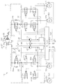
- FIG. 1 The block diagram which shows an example of the vehicle carrying the control apparatus of one Embodiment.
- the hydraulic-circuit figure which shows an example of the damping device shown in FIG.
- the flowchart which shows an engine stop control routine.
- the flowchart which shows an engine restart control routine.
- the model side view which shows the force which acts on the vehicle which stops on a slope.
- the timing chart when braking acceleration is larger than gradient acceleration. Timing chart when not stopping the engine.
- FIGS 1-8 illustrate one embodiment.
- the forward direction of the vehicle will be described as the front of the vehicle.
- the vehicle according to the present embodiment has a so-called idle stop function in order to improve the fuel efficiency and the emission performance. That is, the idle stop function automatically stops the engine in response to the establishment of the predetermined stop condition while the vehicle is traveling, and then automatically restarts the engine in response to the establishment of the predetermined start condition. Therefore, in this vehicle, the engine is automatically stopped during deceleration or stop by the driver's brake operation.
- the vehicle is a front wheel drive vehicle, and in the present embodiment, four wheels, that is, the right front wheel FR, the left front wheel FL, the right rear wheel RR, and the front wheels FR and FL of the left rear wheel RL. Acts as a drive wheel.
- a vehicle transmits a driving force generated by the driving force generator 13 to the front wheels FR and FL, and a driving force generator 13 having an engine 12 that generates a driving force according to the amount of operation of the accelerator pedal 11 by the driver.
- a driving force transmission device 14 The vehicle is also provided with a braking device 16 for applying a braking force corresponding to the amount of operation of the brake pedal 15 by the driver to each of the wheels FR, FL, RR, and RL.
- the driving force generation device 13 is provided with a fuel injection device (not shown) which is disposed in the vicinity of an intake port (not shown) of the engine 12 and has an injector for injecting fuel to the engine 12.
- the driving force generator 13 is driven based on the control of the engine ECU 17 having a CPU, a ROM, a RAM, and the like (not shown).
- the engine ECU means an electronic control unit for an engine.
- the engine ECU 17 is electrically connected to an accelerator opening sensor SE1 disposed in the vicinity of the accelerator pedal 11 and for detecting an operation amount of the accelerator pedal 11 by the driver, that is, an accelerator opening AP.
- the engine ECU 17 calculates the accelerator opening based on the detection signal from the accelerator opening sensor SE1, and controls the driving force generator 13 based on the calculated accelerator opening and the like.
- the driving force transmission device 14 controls the automatic transmission 18, the differential gear 19 that appropriately distributes the driving force transmitted from the output shaft of the automatic transmission 18 and transmits it to the front wheels FR and FL, and the automatic transmission 18 And an AT-ECU (not shown).
- the automatic transmission 18 includes a hydraulic drive power transmission mechanism 20 having a torque converter 20 a as an example of a fluid coupling, and a transmission mechanism 21.
- the braking device 16 comprises a hydraulic pressure generator 28 and a brake actuator 31 having two hydraulic circuits 29 and 30.
- FIG. 2 shows the brake actuator 31 by a two-dot chain line.
- the hydraulic pressure generator 28 has a master cylinder 25, a booster 26 and a reservoir 27.
- the respective hydraulic circuits 29, 30 are connected to the master cylinder 25 of the hydraulic pressure generating device 28, respectively.
- a wheel cylinder 32a for the right front wheel FR and a wheel cylinder 32d for the left rear wheel RL are connected to the first hydraulic circuit 29, and a wheel cylinder 32b for the left front wheel FL is connected to the second hydraulic circuit 30.
- a wheel cylinder 32c for the right rear wheel RR are connected.
- the booster 26 is connected to an intake manifold (not shown) that generates negative pressure when the engine 12 is driven.
- the booster 26 uses the pressure difference between the negative pressure generated in the intake manifold and the atmospheric pressure to boost the operation force of the brake pedal 15 by the driver, that is, the depression force.
- Master cylinder 25 generates a master cylinder pressure PMC according to the operation of brake pedal 15 by the driver, that is, the brake operation.
- the brake fluid is supplied from the master cylinder 25 through the hydraulic circuits 29, 30 into the wheel cylinders 32a to 32d.
- a braking force corresponding to the wheel cylinder pressure PWC in the wheel cylinders 32a to 32d is applied to the wheels FR, FL, RR, and RL.
- the hydraulic circuits 29, 30 are connected to the master cylinder 25 through the conduits 33, 34, respectively, and in the middle of the conduits 33, 34, normally open linear solenoid valves 35a, 35b.
- the linear solenoid valves 35a and 35b are adjusting valves.
- the linear solenoid valves 35a, 35b include a valve seat, a valve body, an electromagnetic coil, and an urging member such as a coil spring. The biasing member biases the valve body away from the valve seat.
- the valve body is displaced in accordance with the current value supplied from the brake ECU 55 described later to the electromagnetic coil. That is, the wheel cylinder pressure PWC in the wheel cylinders 32a to 32d is maintained at a hydraulic pressure corresponding to the value of the current supplied to the linear solenoid valves 35a, 35b.
- a pressure sensor SE2 for detecting a master cylinder pressure PMC is provided at a position closer to the master cylinder 25 than the linear solenoid valve 35a in the pipe line 33.
- the pressure sensor SE2 outputs a detection signal of a value corresponding to the master cylinder pressure PMC to the brake ECU 55.
- the pressure increasing valves 37a, 37b, 37c which are normally open solenoid valves, are branched from the conduits 33, 34 connected to the master cylinder 25 and are connected to the wheel cylinders 32a to 32d in the middle of the conduits 36a to 36d.
- the pressure increasing valves 37a, 37b, 37c and 37d are activated when the pressure increase of each wheel cylinder pressure PWC is restricted, and the pressure reducing valves 38a, 38b, 38c and 38d are activated when the wheel cylinder pressure PWC is decreased.
- reservoirs 39, 40 for temporarily storing the brake fluid that has flowed out from the wheel cylinders 32a-32d through the pressure reducing valves 38a-38d, and pumps 42, 43 operated based on the rotation of the motor 41. And are connected.
- the reservoirs 39 and 40 are connected to the pumps 42 and 43 through the conduits 44 and 45, and are connected to the master cylinder 25 through the conduits 46 and 47, respectively.
- the conduits 46 and 47 are connected to the conduits 33 and 34 at a position closer to the master cylinder 25 than the linear solenoid valves 35a and 35b.
- the pipelines 48, 49 extending from the discharge ports of the pumps 42, 43 are connected to connection portions 50, 51 on a communication path connecting the pressure increase valves 37a to 37d and the linear solenoid valves 35a, 35b.
- the pumps 42 and 43 suck the brake fluid from the reservoirs 39 and 40 and the master cylinder 25 through the pipelines 44, 45, 46 and 47 when the motor 41 rotates, and the brake fluid sucked is pipelines 48 and 49. To discharge.
- the brake ECU 55 means a brake electronic control unit.
- An acceleration sensor SE7 for detecting an acceleration in a direction is electrically connected.
- the acceleration sensor is also referred to as a G sensor.
- the brake ECU 55 is electrically connected to a brake switch SW1 for detecting whether the brake pedal 15 is operated.
- the valves 35a, 35b, 37a to 37d, 38a to 38d, and the motor 41 are electrically connected to the brake ECU 55 as an output system.
- the acceleration sensor SE7 outputs a signal that gives a positive value when the vehicle stops on an uphill road, and outputs a signal that gives a negative value when the vehicle stops on a downhill road Be done.
- the brake ECU 55 is a digital computer comprising a CPU, a ROM, a RAM, etc. (not shown); a driver circuit (not shown) for operating the valves 35a, 35b, 37a to 37d, 38a to 38d; It has a motor driver circuit (not shown) for operation.
- ROM Read Only Memory
- various control processes for example, routines for engine stop control and engine restart control as idle stop processes to be described later, various threshold values, setting values and the like are stored in advance.
- the RAM also stores various types of information that can be appropriately rewritten while the ignition switch (not shown) of the vehicle is on.
- ECUs including the engine ECU 17 and the brake ECU 55 are connected to each other via a bus 56 so as to transmit and receive various information and various control commands as shown in FIG.
- information related to the accelerator opening AP of the accelerator pedal 11 is appropriately transmitted from the engine ECU 17 to the brake ECU 55, while the brake ECU 55 is a control command for permitting the engine 12 to be automatically stopped.
- a stop command, a restart command as a control command to permit automatic restart of the engine 12, and the like are transmitted to the engine ECU 17.
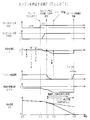
- FIG. 5 shows the relationship of the force acting on the vehicle stopping on the uphill road.
- the slope of the uphill road ie, the inclination angle
- the gravity acting on the vehicle is “g”
- the vehicle is pulled backward by the force “g ⁇ sin ⁇ ” by the action of gravity g.
- the force Fg is a component in the vehicle backward direction of the gravity g acting on the vehicle, that is, a component in the road surface direction, and changes in accordance with the road surface gradient ⁇ .
- a braking force Fpmc corresponding to the master cylinder pressure PMC acts on the vehicle as a force against the force Fg.
- the force Fg and the braking force Fpmc are compared, and if Fpmc ⁇ Fg, the vehicle may be slipped down.
- the acceleration to the rear of the vehicle obtained by dividing the force Fg by the vehicle body weight M is defined as a gradient acceleration Ag. That is, M means a vehicle body mass as a unit system.
- An acceleration obtained by dividing the braking force Fpmc by the vehicle body weight M is defined as a braking acceleration Apmc. If Apmc ⁇ Ag holds, it is determined that there is a possibility that slippage may occur.
- the gradient acceleration Ag is calculated by subtracting the vehicle body speed differential value DVS from the vehicle body acceleration G calculated based on the detection signal from the acceleration sensor SE7.
- the vehicle speed differential value DVS is obtained by temporally differentiating the vehicle speed VS calculated based on the detection signals of the wheel speed sensors SE3 to SE6.
- the vehicle body acceleration G calculated based on the detection signal of the acceleration sensor SE7 includes a gradient acceleration Ag which is a vehicle longitudinal direction component of the gravitational acceleration acting on the vehicle.
- the vehicle speed differential value DVS obtained by time differentiating the vehicle speed VS of the vehicle does not include the gradient acceleration Ag. Therefore, by subtracting the vehicle body speed differential value DVS from the vehicle body acceleration G, the gradient acceleration Ag is obtained.
- the braking acceleration Apmc used to determine the presence or absence of the slippage during traveling before the vehicle is stopped.
- the vehicle body acceleration G calculated based on the detection signal from the acceleration sensor SE7 fluctuates with the fluctuation of the master cylinder pressure PMC, that is, the fluctuation of the braking force on the wheels FR, FL, RR, and RL. Therefore, in the present embodiment, by focusing on the correspondence between the master cylinder pressure and the vehicle body acceleration G, the braking acceleration Apmc as a value corresponding to the master cylinder pressure PMC is acquired based on the vehicle body acceleration G. Be done. That is, master cylinder pressure PMC means a braking force.
- the engine 12 is stopped before the vehicle stops to prevent the slip of the vehicle. Restart in advance. The restart of the engine 12 applies creep torque to the vehicle to prevent the vehicle from slipping down.
- the fuel saving amount Fd saved by the idle stop is smaller than the fuel consumption amount Fst consumed by the restart of the engine 12 after the idle stop, the fuel consumption amount is increased by stopping the idle. Fuel consumption will deteriorate. Therefore, in the present embodiment, when the execution condition of the engine stop control is satisfied, the fuel saving amount Fd which can be saved by the idle stop by the automatic stop of the engine 12 and the fuel consumption amount Fst at the restart of the engine 12 are calculated. Compare. When the fuel saving amount Fd is equal to or more than the fuel consumption amount Fst, the engine 12 is stopped to implement idle stop.
- the present embodiment does not compare the fuel saving amount Fd with the fuel consumption amount Fst, but the predicted idle stop time from the stop to the restart of the engine 12 is assumed as the estimated engine stoppable time Tes. calculate. Then, in the present embodiment, the set time T1 obtained by converting the fuel consumption amount Fc at the time of restart of the engine 12 into the idle time is compared with the estimated engine stoppable time Tes.
- the fuel consumption Fid per unit time when the engine 12 is idle is approximately uniquely determined by the type of vehicle. However, the idle rotation speed of the engine 12 changes between when the air conditioner mounted on the vehicle is driven and when it is not driven.
- the setting time T1 is set based on the upper limit value in the change range of the idle rotation speed, that is, the fuel consumption Fid per unit time at the idle rotation speed at the time of driving the air conditioner.
- this embodiment can adopt a configuration in which it is determined whether the air conditioner is driven or not driven, and the value of the set time T1 is switched according to the determination result.
- the fuel consumption Fst at engine restart is also uniquely determined by the vehicle type.
- the fuel consumption amount Fst at engine restart changes according to the engine operation mode
- the fuel consumption amount Fst according to the operation mode may be adopted.
- a value obtained by converting the fuel consumption amount Fst at engine restart into the idle time is calculated as the set time T1 as the time having the fuel efficiency improvement effect.
- the set time T1 is given by the following equation.
- T1 Fst / Fid (1)
- the engine stoppable estimated time Tes is an estimated time or predicted time in which the engine 12 can be kept stopped from the stop time of the engine 12 to the restart time, and is given by the following equation.
- Tes VS / (DVS + Aet) (2)
- VS is a vehicle speed
- DVS is a vehicle speed differential value
- Aet is an engine torque acceleration.
- the vehicle speed derivative value DVS takes a positive value in the process of deceleration of the vehicle, that is, in the process of increasing the acceleration in the backward direction of the vehicle, in calculation.
- the engine torque acceleration Aet takes a positive value in the engine operating state. The engine torque acceleration Aet will be described later.
- the engine 12 is stopped when the engine stoppable estimated time Tes is equal to or longer than the set time T1, that is, when TesesT1 is satisfied.
- the engine stoppable predicted time Tes is less than the set time T1
- the automatic stop of the engine 12 that is, the idle stop, rather deteriorates the fuel efficiency, so the automatic stop of the engine 12 itself is not performed.
- the slippage lowering determination condition that is, Apmc ⁇ Ag
- the braking force Apmc is equal to or higher than the gradient acceleration Ag
- the braking force condition by which the braking force sufficient to suppress the slippage of the vehicle is secured If Ag Ag is established, the engine 12 is not restarted to prevent slippage. For this reason, in the present embodiment, it is determined whether or not Apmc ⁇ Ag is established whether a braking force sufficient to suppress slippage of the vehicle can be secured when the vehicle is stopped.
- the engine 12 is allowed to stop if the braking force condition, that is, ApmcmcAg, is satisfied even if the condition for the engine stoppable estimated time Tes, that is, TesTT1 is not satisfied.
- “other idle stop condition” excluding the condition of the engine stoppable predicted time Tes, that is, Tes ⁇ T1 and the braking force condition, that is, ApmcAgAg, is set.
- the "other IS condition”, that is, the “other idle stop condition” is that "the brake switch SW1 is on”, that is, the brake switch is on; "master cylinder pressure PMC exceeds the specified pressure P1 That is, that each condition that PMC> P1 is satisfied; and that the vehicle speed VS is less than the prescribed speed V1, for example, 20 km / h is satisfied that each condition that VS ⁇ V1 is satisfied is AND condition.
- the "other idle stop condition” may be changed to an appropriate condition such as eliminating one of the brake switch on condition and the master cylinder pressure condition.
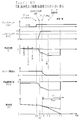
- FIGS. 6 to 8 show timing charts of control modes of the present embodiment.
- the signal of the brake switch SW1 before stopping the vehicle on the uphill, the master cylinder pressure PMC, the vehicle acceleration G output from the acceleration sensor SE7, the engine rotation speed, the vehicle speed VS, and the vehicle speed differential value DVS Shows the transition of In the present embodiment, the wheel speed is used as the vehicle speed VS.
- the vehicle body speed VS can be obtained by adding an integrated value obtained by integrating wheel acceleration, which is a time differential value of the wheel speed, for each unit time to the previous wheel speed.
- the vehicle acceleration G and the vehicle speed differential value DVS are shown to be different in positive and negative states from the vehicle acceleration G detected by the acceleration sensor SE7 and the calculated vehicle speed differential value DVS. That is, in FIG. 6 to FIG. 8, the vehicle body acceleration G and the vehicle body speed differential value DVS are shown such that the rear direction of the vehicle takes a negative value.
- FIG. 6 is a timing chart in the case where the engine 12 is stopped because the condition for the estimated engine stoppable time Tes to be the set time T1 or more is satisfied.
- the vehicle is traveling with the engine 12 being driven.
- the vehicle acceleration G during traveling of the vehicle includes acceleration components such as acceleration Ag corresponding to the gradient; acceleration Aet corresponding to the engine torque, ie, creep torque acceleration; and acceleration Ad corresponding to the drag. Including. Assuming that the acceleration acting on the front of the vehicle is "positive” and the acceleration acting on the rear of the vehicle is "negative", the gradient acceleration Ag is negative, the engine torque acceleration Aet is positive, and the acceleration Ad is a negative value. As a result of these accelerations being applied to the vehicle, the vehicle acceleration G is detected by the acceleration sensor SE7.
- the acceleration sensor SE7 outputs the acceleration in the backward direction of the vehicle as a positive value for the sake of convenience of calculation, unlike the positive / negative of the actual acceleration in FIG.
- the acceleration Ad corresponding to the drag means a negative acceleration due to running resistance between the wheel and the road surface.
- the brake switch SW1 When the driver operates the brake pedal 15 at time t1 while the vehicle is traveling, that is, the brake switch SW1 is turned on when the driver depresses the brake pedal 15, the master cylinder pressure PMC is increased by this brake operation, and the braking force is applied to the wheels. Be done. As a result, the vehicle speed VS starts to decrease from time t1. At this time, the braking acceleration Apmc for the master cylinder pressure PMC is applied to the vehicle as a negative acceleration in the direction opposite to the traveling direction, that is, in the backward direction, so the vehicle body acceleration G is an acceleration for the respective master cylinder pressure PMC. Apmc decreases and takes a negative value. Further, the master cylinder pressure PMC reaches the defined pressure P1 by the brake operation.
- the vehicle speed VS is decelerated at a change rate equal to the vehicle acceleration G reduced by the application of the braking acceleration Apmc. In FIG. 6, G ⁇ 0. Eventually, the vehicle speed VS becomes less than or equal to the specified speed V1.
- the engine stoppable estimated time Tes is a stop time of the engine 12, that is, from the present time when it is assumed that the engine 12 is restarted to prevent a slip of the vehicle after stopping when the engine 12 is stopped. Calculated as the time between the start of restart. That is, the engine stoppable estimated time Tes is calculated as the time that is expected to be capable of holding the engine 12 in the stop state.
- the vehicle body when decelerating with the vehicle acceleration G to which the acceleration Aet corresponding to the engine torque is added It corresponds to the speed.
- the dashed-two dotted line in FIG. 6 shows the speed profile in the case of decelerating by the vehicle body acceleration G to which the acceleration Aet for engine torque was added.
- the engine stoppable estimated time Tes is calculated on the assumption of the deceleration process in the engine stop state.
- the engine stoppable expected time Tes and the set time T1 are compared, and if Tes> T1 holds, the fuel efficiency improvement effect is obtained, so the engine 12 is stopped from time t2. As a result, the engine rotational speed decreases from time t2 and eventually becomes zero. When the engine rotation speed becomes zero, the engine torque component disappears, so the actual vehicle speed VS decreases along the solid line in FIG. 6 in the same manner as the expected vehicle speed. In the period from time t2 to time t3, the engine stoppable estimated time Tes may be calculated using the variable acceleration Aet according to the gradually decreasing engine torque.
- the engine 12 is stopped even if the estimated engine stoppable time Tes is shorter than the set time T1, that is, Tes ⁇ T1. This is because it is not necessary to restart the engine 12 for the purpose of preventing slippage after stopping. In the present embodiment, the engine 12 is also stopped even when it is not necessary to restart the engine when the vehicle is stopped.
- the engine restart start time is determined so that the slippage lowering distance L can be suppressed to the allowable distance La or less.
- the predicted time T2 sequentially calculated in the deceleration process of the vehicle after the engine stop reaches the restart required time Teng as the time required from the restart start of the engine 12 to the restart end.
- the required time for restart Teng which is predetermined for each vehicle, decreases, restart of the engine 12 is started.
- the restart of the engine 12 is completed before the slippage lowering distance L reaches the allowable distance La.
- the brake ECU 55 executes the idle stop control routine at predetermined intervals, for example, every 0.01 second.
- an engine restart control routine The engine restart control in the idle stop control routine is performed when the master cylinder pressure PMC becomes lower than the specified pressure Px when the operation amount of the brake pedal 15 returns below the specified amount, or the accelerator opening AP> 0.
- the engine 12 is restarted when a predetermined restart condition such as time is satisfied.
- the engine restart control in the present embodiment includes slip reduction prevention control that prevents slippage of the vehicle after stopping.
- the engine restart control routine shown in FIG. 4 shows a part of the engine stop control that restarts the engine 12 for slippage prevention control.
- the brake ECU 55 executes an engine stop control routine shown in FIG. 3 while the vehicle is traveling in the engine operating state.
- the engine stop control routine is a process for stop control that permits the automatic stop of the engine 12 when a predetermined stop condition is satisfied.
- step S11 the brake ECU 55 first determines whether “other idle stop conditions” (other IS conditions) are satisfied. If the "other idle stop condition” is satisfied, the process proceeds to step S12. If the “other idle stop condition” is not satisfied, the routine is ended.
- the “other idle stop condition” corresponds to the execution condition of the stop control, and the brake ECU 55 that determines whether the “other idle stop condition” is satisfied also functions as a first determination unit. .
- Step S11 corresponds to a first determination step.
- step S12 the brake ECU 55 calculates an estimated engine stoppable time Tes.
- the brake ECU 55 determines whether or not "the estimated engine stoppable time Tes is equal to or longer than a set time T1 at which the fuel efficiency improvement effect is achieved", that is, Tes T T1. If Tes ⁇ T1 is established, the process proceeds to step S15, and if Tes ⁇ T1 is not established, the process proceeds to step S14.
- the brake ECU 55 also functions as a third determination unit by determining the engine stoppable estimated time Tes and determining whether Tes ⁇ T1 holds. Steps S12 and S13 correspond to a third determination step.
- step S15 the stop of the engine 12 is permitted. That is, the brake ECU 55 transmits a stop command to the engine ECU 17. As a result, the engine ECU 17 stops the engine 12.
- the brake ECU 55 that permits the engine 12 to stop also functions as a stop control unit. Step S15 corresponds to the stop control step.
- the brake ECU 55 determines whether or not "the braking acceleration Apmc is equal to or higher than the gradient acceleration Ag as a threshold value" in step S14. That is, it is determined whether Apmc ⁇ Ag holds.
- the establishment of Apmc ⁇ Ag means that a braking force sufficient to prevent slippage without restarting the engine 12 is secured. Therefore, if Apmc ⁇ Ag, the brake ECU 55 proceeds to step S15 and permits the engine 12 to stop. That is, the brake ECU 55 transmits a stop command to the engine ECU 17. As a result, the engine ECU 17 stops the engine 12.
- the brake ECU 55 that determines whether Apmc ⁇ Ag holds also functions as a fourth determination unit. Step S14 corresponds to a fourth determination step.
- step S14 when it is determined in step S14 that Apmc ⁇ Ag is not established, the routine ends. In this case, stopping of the engine 12 is not permitted. That is, since the fuel efficiency improvement effect by idle stop can not be obtained, the stop of the engine 12 is not permitted.
- the timing chart shown in FIG. 6 describes the process when TesTT1 as the process when stopping the engine 12. If the driver operates the brake pedal 15 at time t1 while the vehicle is traveling with the engine operating condition, the brake switch SW1 is turned on and the master cylinder pressure PMC rises to reach the specified pressure P1. By applying a braking force corresponding to master cylinder pressure PMC to wheels FR, FL, RR, and RL, the vehicle decelerates, and the vehicle speed VS becomes equal to or less than a specified speed V1. As a result, at time t2, "other idle stop conditions" are satisfied. That is, each condition of brake switch ON; master cylinder pressure PMC> prescribed pressure P1; and vehicle body speed VS ⁇ prescribed speed V1 is satisfied under the AND condition.
- an engine stoppable estimated time Tes is next obtained, and it is determined whether Tes ⁇ T1 is satisfied. If Tes ⁇ T1 holds, the engine 12 is stopped from time t2. As a result, the engine torque component disappears by time t3, and the vehicle speed VS decreases along the solid line in FIG. At time t4, the vehicle stops.
- This engine restart control routine is for permitting automatic restart of the engine 12 for the purpose of suppressing slippage of the vehicle after stopping within the allowable range when a predetermined restart condition is satisfied. Processing.
- the engine restart control routine shown in FIG. 4 is repeatedly executed by the brake ECU 55 at a constant control cycle, for example, every 0.01 seconds, while traveling uphill with the engine 12 stopped.
- step S21 the brake ECU 55 determines whether “slipping of the vehicle occurs after stopping” by comparing the braking acceleration Apmc and the gradient acceleration Ag. That is, it is determined whether Apmc ⁇ Ag holds.
- the brake ECU 55 determines whether Apmc ⁇ Ag holds or not also functions as a second determination unit.
- Step S21 corresponds to a second determination step.
- the brake ECU 55 permits the restart of the engine 12 in step S24. That is, the brake ECU 55 transmits a restart command to the engine ECU 17.
- the engine ECU 17 When the engine ECU 17 receives the restart command, the engine ECU 17 restarts the engine 12 and transmits a signal to the effect that the restart processing has been completed to the brake ECU 55.
- the brake ECU 55 that has received the signal from the engine ECU 17 determines that the restart of the engine 12 is completed.
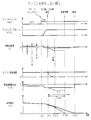
- the estimated engine stoppable time Tes is smaller than the set time T1, that is, Tes ⁇ T1.
- the timing chart in the case where the braking force capable of suppressing the slippage drop is secured is shown as the braking acceleration Apmc is larger than the gradient acceleration Ag.
- the braking acceleration Apmc is larger than the gradient acceleration Ag, a braking force sufficient to prevent slippage is secured. Therefore, there is no need to restart the engine 12 for the purpose of preventing slippage. Therefore, at time t13 when Apmc> Ag is established, the stop of the engine 12 is permitted. As a result, from time t13, the engine rotational speed decreases and eventually becomes zero. When the engine rotational speed becomes zero at time 14, the engine torque disappears. Therefore, the actual vehicle speed VS decreases along the solid line in FIG. 7 as expected. Since a relatively strong braking force is secured when the vehicle is stopped at time t15, the vehicle does not slip down even if the engine 12 is not restarted.
- FIG. 8 shows a timing chart when the engine is not stopped.
- the brake pedal 15 is operated at time t21 while the vehicle is traveling in the engine operating state, the brake switch SW1 is turned on, and the master cylinder pressure PMC rises to reach the defined pressure P1.
- Tes> T1 is established by using the engine stoppable estimated time Tes assumed to stop at time t24. In the example of FIG. 8, since Tes> T1 is not established, the fuel consumption improvement effect can not be obtained even if the engine 12 is stopped.
- the master cylinder pressure PMC is relatively small at about the prescribed pressure P1, that is, the braking acceleration Apmc is smaller than the gradient acceleration Ag, so that the braking force that can suppress the slippage is not secured. For this reason, in order to prevent slippage of the vehicle after stopping, a creep torque is required. Thus, the engine 12 is not stopped. The actual vehicle speed VS decreases along the solid line in FIG. 8 because the acceleration Aet corresponding to the engine torque does not disappear. Since the creep torque is given by the engine 12 continuing the driving after the stop, the slippage of the vehicle does not occur.
- the brake ECU 55 for automatically stopping the engine 12 and automatically restarting the fuel consumption Fd is equal to or more than the fuel consumption Fst required to restart the engine 12 when the “other idle stop condition” is satisfied. It is determined whether or not.
- the fuel saving amount Fd means the amount of fuel that can be saved in the engine stop period, that is, the idle stop time from the engine stop to the restart of the engine 12 performed for the purpose of preventing slippage after stopping. If the fuel saving amount Fd is the fuel consumption amount Fst or more, the brake ECU 55 permits the engine 12 to stop. Therefore, for example, when it is possible to secure only the engine stop period in which the fuel consumption Fst is larger than the fuel saving amount Fd, the engine 12 can not be stopped. Therefore, the fuel consumption improvement effect can be further obtained as compared with the conventional case.
- the brake ECU 55 is an estimated value of the engine stop period from the engine stop to the restart of the engine 12 performed for the purpose of preventing slippage after stopping when the "other idle stop conditions" are satisfied.
- An engine stoppable estimated time Tes is calculated.
- the brake ECU 55 determines whether the estimated engine stoppable time Tes is equal to or longer than the set time T1. That is, the brake ECU 55 does not directly compare the fuel saving amount Fd with the fuel consumption amount Fst.
- the brake ECU 55 uses the fuel consumption amount Fid per unit time in the idle state of the engine 12 to convert the fuel amounts Fd and Fst into time corresponding to the idle time, respectively, to obtain the estimated engine stoppable time Tes.
- the set time T1 is obtained.
- the brake ECU 55 compares the estimated engine stoppable time Tes with the set time T1. Therefore, the brake ECU 55 does not obtain the fuel saving amount Fd and the fuel consumption amount Fst, but uses the estimated engine stoppable time Tes, which is a time conversion value thereof, and the setting time T1 to obtain the fuel saving amount Fd It can be determined indirectly that it is Fst or more. Therefore, in the present embodiment, the determination can be made by a relatively simple process using the engine stoppable estimated time Tes which can be acquired by calculating from the detection results of the existing wheel speed sensors SE3 to SE6.
- the brake ECU 55 When the fuel saving amount is less than the fuel consumption amount, the brake ECU 55 generates a gradient acceleration Ag corresponding to the force Fg of the gradient component of gravity acting on the vehicle according to the operation amount of the brake pedal 15, that is, the stepping amount.
- the braking acceleration Apmc is determined from the master cylinder pressure PMC. If Apmc ⁇ Ag, it is determined that slipping does not occur after the vehicle is stopped, and the engine 12 is permitted to stop. That is, when the braking force capable of resisting the force Fg of the gradient component of gravity acting on the vehicle when the vehicle is stopped, the stop of the engine 12 is permitted. Therefore, the fuel consumption improvement effect can be obtained by increasing the implementation frequency of the idle stop.
- restart of the engine 12 is started so as to be completed by the time the vehicle is stopped. More specifically, when a slippage of the vehicle is predicted to occur, restart of the engine 12 is started when the predicted time T2 until the vehicle stops reaches the required restart time Teng. For this reason, slippage of the vehicle does not occur after stopping, and slippage after stopping of the vehicle on the uphill road can be suitably prevented.
- the brake ECU 55 determines whether or not a slippage occurs after the vehicle is stopped, a braking acceleration Apmc determined from the master cylinder pressure PMC according to the operation amount of the brake pedal 15, ie, the depression amount, the vehicle acceleration G and the vehicle speed This is performed using gradient acceleration Ag determined from the difference with the differential value DVS.
- the brake ECU 55 determines that "a slip of the vehicle occurs". Therefore, it is possible to accurately determine the necessity of restarting the engine 12 for the purpose of preventing slippage of the vehicle.
- the estimated engine stoppable time Tes obtained by converting the fuel saving amount Fd and the set value F1 corresponding to the fuel consumption Fc into idle time is compared with the set time T1.
- the fuel injection device has an injector for injecting fuel into the combustion chamber of the engine 12.
- the fuel saving amount Fd is calculated by multiplying the amount of fuel consumed per unit time under the engine idle condition by the fuel injection device by the engine stop time from the stop of the engine 12 to the restart.
- the memory of the brake ECU 55 stores a set value F1 corresponding to the actual fuel consumption amount Fc acquired at engine start.
- the brake ECU 55 functioning as the third determination unit is configured to determine whether the fuel reduction amount Fd obtained by the above calculation is equal to or greater than the set value F1.
- the engine 12 is allowed to stop. Instead of this, the engine may not be stopped. That is, at least when the fuel consumption is to be deteriorated, the engine 12 may not be stopped.
- the allowable amount ⁇ may be set with respect to the fuel consumption Fc.
- an allowable time T ⁇ corresponding to the allowable amount ⁇ may be set with respect to the estimated engine stoppable time Tes. Then, the third determination unit may be configured to determine that FdFFc + F ⁇ or Tes ⁇ T1 + T ⁇ .
- the determination condition of the third determination unit may be Fd ⁇ Fc ⁇ F ⁇ or Tes ⁇ T1 ⁇ T ⁇ .
- the set value may be a value set according to the fuel consumption at the time of engine restart, and may be a value in which a predetermined allowable value is considered with respect to the fuel consumption and the conversion time of the fuel consumption. .
- the braking acceleration Apmc is compared with the gradient acceleration Ag, that is, the threshold value, at the time of the slip down determination.
- the braking force may be compared with the threshold value as the force Fg of the vehicle longitudinal direction component of the gravity acting on the vehicle, that is, the road surface direction component.
- master cylinder pressure PMC may be compared with a threshold as a force equivalent to master cylinder pressure of force Fg.
- the braking acceleration Apmc may be acquired based on the master cylinder pressure PMC detected by the pressure sensor SE2.
- the memory of the brake ECU 55 stores, for example, a map (not shown) indicating the correspondence between the master cylinder pressure PMC and the braking acceleration Apmc or the braking force Fpmc.
- the brake ECU 55 acquires the braking acceleration Apmc or the braking force Fpmc by referring to the map based on the master cylinder pressure PMC. Then, the brake ECU 55 may be configured to determine the presence or absence of slippage by comparing the braking acceleration Apmc with the gradient acceleration Ag, or by comparing the braking force Fpmc with the force Fg.
- the slippage of the vehicle at the time of stopping on the uphill may be allowed if it is small. That is, the allowable distance La is set to La ⁇ 0, and the engine 12 is restarted while the slippage lowering distance L is within the allowable distance La. It is determined whether or not a slippage of the vehicle after the stoppage occurs while traveling uphill while the engine 12 is stopping. When it is predicted that "slipping occurs", restart of the engine 12 is started so as to be completed by the time the sling lowering distance L of the vehicle exceeds the allowable distance La.
- the brake ECU 55 permits start of restart of the engine 12 when the predicted time T2 represented by the sum of the time Ta and the time Tb reaches the required restart time Teng.
- the larger the road surface gradient ⁇ the larger the value of the allowable distance La may be set.
- the allowable distance La is set to “0” until the road surface gradient ⁇ reaches a constant value, and the allowable distance La is increased according to the increase of the road surface gradient ⁇ after the road surface gradient ⁇ exceeds a constant value.
- the allowable distance La is the one described in the above embodiment. When these configurations are adopted, it is preferable to calculate the estimated engine stoppable time Tes by the following equation.
- Tes VS / (DVS + Aet) + Tb-Teng (4)
- the engine 12 is restarted to add creep torque to the braking force to prevent the vehicle from slipping down.
- the gradient acceleration Ag is larger than the sum of the creep acceleration Ac due to creep torque and the braking acceleration Apmc, that is, if Ac + Apmc ⁇ Ag, then a slippage occurs. Therefore, when Ac + Apmc ⁇ Ag holds, a configuration may be adopted in which brake pressure is applied to prevent slippage. Specifically, when Ac + Apmc ⁇ Ag holds, the motor 41 is driven to drive the pumps 42 and 43.
- the vehicle slips down after stopping based on the braking acceleration Apmc determined from the master cylinder pressure PMC according to the operation force of the brake pedal 15, ie, the pedaling force, and the detection result of the vehicle body acceleration G. It was like that. It is also possible to change this and make the same determination based on other detected values. For example, it is possible to confirm the braking force and the braking acceleration of the vehicle by using the operation amount of the brake pedal 15, that is, the detection value of the depression amount instead of the detection value of the master cylinder pressure PMC. In this case, a sensor for detecting the amount of depression of the brake pedal 15 is provided to the vehicle.
- the acceleration by the brake can also be confirmed by removing the acceleration generated by the engine by the vehicle acceleration G, the acceleration by the rolling resistance, the road surface gradient acceleration, the acceleration by the air resistance or the like from the vehicle acceleration G. Further, it is also possible to perform the above determination by providing a sensor for detecting the pitch of the vehicle body and grasping the road surface gradient ⁇ by a signal from the sensor.
- the vehicle speed VS and the vehicle speed differential value DVS are used. This may be modified to use wheel speed and wheel acceleration. As the vehicle body speed, it is possible to use one calculated using at least one of the wheel speed sensors SE3 to SE6 or a value acquired by a car navigation system.
- Vehicles are not limited to two-wheel drive vehicles.
- the vehicle control device of the present invention can be similarly applied to vehicles of other drive systems such as four-wheel drive vehicles.
- T1 setting time which is an example of setting value.
- ⁇ Road surface gradient. L ... slip down distance. La ... allowable distance.
- VS body speed.
- DVS body speed derivative value.
- Ag gradient acceleration.
- Fpmc braking force.
- Apmc braking acceleration.
- Aet engine torque acceleration.
- Fd Fuel savings.
- Fst Fuel consumption.
- F1 setting value. Teng ... required time to restart.
Abstract
Description
T1=Fst/Fid … (1)
またエンジン停止可能予想時間Tesは、エンジン12の停止時点から再始動時点までエンジン12を停止状態に保持できる予想時間つまり予測時間であり、次式によって与えられる。
Tes=VS/(DVS+Aet)…(2)
ここでVSは車体速度であり、DVSは車体速度微分値であり、Aetはエンジントルク加速度である。但し本例では、車体速度微分値DVSは計算上、車両の減速過程つまり車両後方向への加速度が増加する過程で、正の値をとる。またエンジントルク加速度Aetは、エンジン運転状態で正の値をとる。エンジントルク加速度Aetは後述する。 In addition, the fuel consumption Fst at engine restart is also uniquely determined by the vehicle type. Of course, in the present embodiment, when the fuel consumption amount Fst at engine restart changes according to the engine operation mode, the fuel consumption amount Fst according to the operation mode may be adopted. However, in the present embodiment, a value obtained by converting the fuel consumption amount Fst at engine restart into the idle time is calculated as the set time T1 as the time having the fuel efficiency improvement effect. The set time T1 is given by the following equation.
T1 = Fst / Fid (1)
Further, the engine stoppable estimated time Tes is an estimated time or predicted time in which the
Tes = VS / (DVS + Aet) (2)
Here, VS is a vehicle speed, DVS is a vehicle speed differential value, and Aet is an engine torque acceleration. However, in the present embodiment, the vehicle speed derivative value DVS takes a positive value in the process of deceleration of the vehicle, that is, in the process of increasing the acceleration in the backward direction of the vehicle, in calculation. Further, the engine torque acceleration Aet takes a positive value in the engine operating state. The engine torque acceleration Aet will be described later.
Tes=VS/(DVS-Aet)-Teng …(3)
さてブレーキECU55は、予め設定された所定周期たとえば0.01秒周期毎にアイドルストップ制御ルーチンを実行する。このアイドルストップ制御ルーチンは、燃費向上および環境上の効果などを期待し、エンジン12を自動的に停止させるための図3に示すエンジン停止制御ルーチンと、エンジン12を再始動させるための図4に示すエンジン再始動制御ルーチンとを含む。アイドルストップ制御ルーチンにおけるエンジン再始動制御は、ブレーキペダル15の操作量が規定量以下に戻ることでマスタシリンダ圧PMCが規定圧Px以下になったときや、あるいはアクセル開度AP>0になったときなどの予め決められた再始動条件の成立時に、エンジン12を再始動させる。本実施形態におけるエンジン再始動制御は、停車後の車両のズリ下がりを防止するズリ下がり防止制御を含む。図4に示すエンジン再始動制御ルーチンは、エンジン停止制御のうちの、ズリ下がり防止制御のためにエンジン12を再始動させる制御部分を示す。 In the present embodiment, the engine stoppable expected time Tes is calculated using the above-mentioned equation (2), but the following equation can also be adopted in consideration of the restart required time Teng.
Tes = VS / (DVS-Aet) -Teng (3)
The
Tes=VS/(DVS+Aet)+Tb-Teng …(4)
前記実施形態では、エンジン12を再始動させて、制動力にクリープトルクを加えることで、車両のズリ下がりを防止した。この場合には、路面勾配θが大きくクリープトルクによるクリープ加速度Acと制動加速度Apmcとの和よりも勾配加速度Agのほうが大きい場合つまりAc+Apmc<Agが成立する場合には、ズリ下がりが発生する。そこでAc+Apmc<Agが成立する場合には、ブレーキ加圧を行ってズリ下がりを防止する構成も採用できる。具体的にはAc+Apmc<Agが成立した場合には、モータ41を駆動させてポンプ42,43を駆動させる。さらにリニア電磁弁35a,35bに、勾配加速度Agの大きさに応じた電流値で電流を供給してホイールシリンダ圧PWCを制御目標値に増圧することでブレーキ加圧を行う。その後、ブレーキ圧を制御目標圧に保持できる電流値を、リニア電磁弁35a,35bに供給する。この構成によれば、たとえば路面勾配θが大きいためにクリープトルクを加えただけではズリ下がりを防止できないような場合でも、車両を登坂路にズリ下がることなく停止させることができる。 The slippage of the vehicle at the time of stopping on the uphill may be allowed if it is small. That is, the allowable distance La is set to La ≧ 0, and the
Tes = VS / (DVS + Aet) + Tb-Teng (4)
In the embodiment, the
Claims (5)
- 車両のエンジンを自動的に停止させるための停止制御と、前記エンジンを自動的に再始動させるための再始動制御とを行う車両制御装置であって、前記車両制御装置は、
「前記停止制御の実行条件が成立した」か否か判定するように構成された第1判定部と;
「前記停止制御の実行条件が成立する」と判定された場合には、前記エンジンの停止を許可するように構成された停止制御部と;
前記エンジンが停止された状態での前記車両による坂路走行時に、「停車後の前記車両のズリ下がりが発生する」か否か判定するように構成された第2判定部と;
「前記ズリ下がりが発生する」と判定されたときには、前記車両のズリ下がり距離が許容距離を超えるまでに前記エンジンの再始動が完了するように、前記エンジンの再始動の開始を許可するように構成された再始動制御部と;
前記エンジンの停止前に、前記エンジンの停止から前記再始動までのエンジン停止期間で節減しうる燃料節減量を予測するように構成された第3判定部であって、前記第3判定部は、「前記燃料節減量が、前記エンジンの前記再始動に要する燃料消費量に応じて設定された設定値以上である」か否か判定するように構成された、前記第3判定部と
を備え、
「前記燃料節減量が前記設定値未満である」と判定された場合には前記停止制御部は、前記停止制御の実行条件が成立しても前記エンジンの停止を許可しないように構成されている、
車両制御装置。 A vehicle control apparatus that performs stop control for automatically stopping an engine of a vehicle and restart control for automatically restarting the engine, the vehicle control apparatus comprising:
A first determination unit configured to determine whether "the execution condition of the stop control is satisfied";
A stop control unit configured to permit stopping of the engine when it is determined that "the execution condition of the stop control is satisfied";
A second determination unit configured to determine whether or not “slipping of the vehicle after stopping occurs” when traveling on a slope with the vehicle in a state where the engine is stopped;
When it is determined that "the slip is occurring", the restart of the engine is permitted to be started so that the restart of the engine is completed before the slip distance of the vehicle exceeds the allowable distance. Configured restart control;
A third determination unit configured to predict a fuel saving amount that can be saved in the engine stop period from the stop of the engine to the restart before the stop of the engine, wherein the third determination unit is And a third determination unit configured to determine whether “the fuel saving amount is equal to or more than a set value set according to the fuel consumption amount required for the restart of the engine”.
When it is determined that "the fuel saving amount is less than the set value", the stop control unit is configured not to permit the stop of the engine even if the execution condition of the stop control is satisfied. ,
Vehicle control device. - 前記車両はブレーキ操作部を備え、
前記車両制御装置はさらに第4判定部を備え、
前記第4判定部は、「前記ブレーキ操作部の操作量に応じた制動力が、停車後の前記車両のズリ下がりを抑えうる閾値以上に確保されている」か否か判定するように構成され、
「前記制動力が前記閾値以上に確保されている」と判定された場合には前記停止制御部は、「前記燃料節減量が前記設定値未満である」と判定された場合でも、前記エンジンの停止を許可するように構成されている、
請求項1記載の車両制御装置。 The vehicle includes a brake operating unit.
The vehicle control device further includes a fourth determination unit,
The fourth determination unit is configured to determine whether or not "the braking force corresponding to the operation amount of the brake operation unit is secured at or above a threshold that can suppress slippage of the vehicle after stopping." ,
When it is determined that "the braking force is secured above the threshold value", the stop control unit may determine that the amount of fuel saved is less than the set value, even if it is determined that Configured to allow outages,
The vehicle control device according to claim 1. - 前記第3判定部は、前記エンジンの停止から再始動までの時間としてのエンジン停止可能予想時間を求めるように構成され、
前記第3判定部は、「前記燃料節減量が前記設定値以上である」か否かの判定を、前記エンジン停止可能予想時間が、前記設定値を前記エンジンのアイドル時間に換算した設定時間以上であるか否か判定することによって行うように構成されている、
請求項1または2記載の車両制御装置。 The third determination unit is configured to obtain an estimated engine stoppable time as a time from stop to restart of the engine,
The third determination unit determines whether or not “the fuel saving amount is equal to or more than the set value”, or more than the set time obtained by converting the set value to the idle time of the engine. Configured to determine whether or not
The vehicle control device according to claim 1. - 前記車両は車速検出部を有し、
前記第3判定部は、前記車速検出部によって検出された車体速度を取得するように、かつ前記車体速度が時間微分されることで生成する車体速度微分値を取得するように構成され、
前記前記第3判定部は、前記エンジンの停止によって消滅するエンジントルク分の加速度を前記車体速度微分値から除いた値で、前記車体速度を除算することで、前記エンジン停止可能予想時間を算出するように構成されている、
請求項3記載の車両制御装置。 The vehicle has a vehicle speed detector.
The third determination unit is configured to obtain a vehicle speed detected by the vehicle speed detection unit, and to obtain a vehicle speed derivative value generated by time-differentiating the vehicle speed.
The third determination unit calculates the estimated engine stoppable time by dividing the vehicle body speed by a value obtained by removing an acceleration for an engine torque which disappears due to a stop of the engine from the vehicle body speed differential value. Is configured as
The vehicle control device according to claim 3. - 車両のエンジンを自動的に停止させるための停止制御と、前記エンジンを自動的に再始動させるための再始動制御とを行う車両制御方法であって、前記車両制御方法は、
「前記停止制御の実行条件が成立した」か否か判定することと;
「前記停止制御の実行条件が成立する」と判定された場合には、前記エンジンの停止を許可することと;
前記エンジンが停止された状態での前記車両による坂路走行時に、「停車後の前記車両のズリ下がりが発生する」か否か判定することと;
「前記ズリ下がりが発生する」と判定されたときには、前記車両のズリ下がり距離が許容距離を超えるまでに前記エンジンの再始動が完了するように、前記エンジンの再始動を開始することと;
前記エンジンの停止前に、前記エンジンの停止から前記再始動までの停止期間で節減しうる燃料節減量を予測することと;
「前記燃料節減量が、前記エンジンの前記再始動に要する燃料消費量に応じて設定された設定値以上である」か否か判定することと;
「前記燃料節減量が前記設定値未満である」と判定された場合には、前記停止制御の実行条件が成立しても前記エンジンの停止を許可しないことと
を備える、車両制御方法。 A vehicle control method for performing stop control for automatically stopping an engine of a vehicle and restart control for automatically restarting the engine, the vehicle control method comprising:
Determining whether "the execution condition of the stop control is satisfied";
Allowing the engine to stop when it is determined that "the execution condition of the stop control is satisfied";
Determining whether or not "slipping of said vehicle after stopping occurs" when traveling on a slope road with said vehicle in a state where said engine is stopped;
When it is determined that "the slip is occurring", restart of the engine is started so that the restart of the engine is completed before the slip distance of the vehicle exceeds the allowable distance;
Predicting the fuel savings that can be saved in the stop period between the stop of the engine and the restart before the stop of the engine;
Determining whether "the amount of fuel savings is equal to or greater than a set value set according to the amount of fuel consumption required for the restart of the engine";
The vehicle control method according to any one of the preceding claims, wherein, when it is determined that "the fuel saving amount is less than the set value", stopping of the engine is not permitted even if the execution condition of the stop control is satisfied.
Priority Applications (2)
| Application Number | Priority Date | Filing Date | Title |
|---|---|---|---|
| CN201180046184.XA CN103124838B (en) | 2010-09-30 | 2011-09-27 | Controller of vehicle and control method for vehicle |
| DE112011103318.4T DE112011103318B4 (en) | 2010-09-30 | 2011-09-27 | Vehicle control device and vehicle control method |
Applications Claiming Priority (2)
| Application Number | Priority Date | Filing Date | Title |
|---|---|---|---|
| JP2010222222A JP5672917B2 (en) | 2010-09-30 | 2010-09-30 | Vehicle control device |
| JP2010-222222 | 2010-09-30 |
Publications (1)
| Publication Number | Publication Date |
|---|---|
| WO2012043530A1 true WO2012043530A1 (en) | 2012-04-05 |
Family
ID=45892971
Family Applications (1)
| Application Number | Title | Priority Date | Filing Date |
|---|---|---|---|
| PCT/JP2011/071995 WO2012043530A1 (en) | 2010-09-30 | 2011-09-27 | Vehicle control device and vehicle control method |
Country Status (4)
| Country | Link |
|---|---|
| JP (1) | JP5672917B2 (en) |
| CN (1) | CN103124838B (en) |
| DE (1) | DE112011103318B4 (en) |
| WO (1) | WO2012043530A1 (en) |
Families Citing this family (9)
| Publication number | Priority date | Publication date | Assignee | Title |
|---|---|---|---|---|
| JP5737203B2 (en) * | 2012-02-02 | 2015-06-17 | 株式会社デンソー | Engine control device |
| JP5935549B2 (en) * | 2012-07-04 | 2016-06-15 | 日産自動車株式会社 | Automatic engine stop control device for vehicle |
| CN105452630B (en) * | 2013-07-23 | 2018-08-31 | 加特可株式会社 | The control device and its control method of vehicle |
| DE102013114270A1 (en) * | 2013-09-16 | 2015-03-19 | Hyundai Motor Company | Leerlaufabschaltungsbedingungsmittingungsverfahren an internal combustion engine |
| JP2015117593A (en) * | 2013-12-17 | 2015-06-25 | 株式会社ケーヒン | Engine stop/start control device |
| CN104763544A (en) * | 2014-01-07 | 2015-07-08 | 博世(中国)投资有限公司 | Fuel saving data processing method and system based on engine start-stop function and car |
| JP2017007505A (en) * | 2015-06-22 | 2017-01-12 | トヨタ自動車株式会社 | Vehicle control device |
| JP6833273B2 (en) * | 2016-12-22 | 2021-02-24 | ダイハツ工業株式会社 | Vehicle control device |
| JP7099028B2 (en) * | 2018-04-25 | 2022-07-12 | 株式会社アドヴィックス | Vehicle travel path determination device |
Citations (2)
| Publication number | Priority date | Publication date | Assignee | Title |
|---|---|---|---|---|
| JP2005282453A (en) * | 2004-03-30 | 2005-10-13 | Toyota Motor Corp | Control device for vehicle |
| JP2010053867A (en) * | 2008-08-29 | 2010-03-11 | Robert Bosch Gmbh | Engine start/stop unit for automatic-supply/intercept of internal combustion engine |
Family Cites Families (12)
| Publication number | Priority date | Publication date | Assignee | Title |
|---|---|---|---|---|
| JP3635927B2 (en) * | 1998-06-19 | 2005-04-06 | 株式会社デンソー | Automatic engine stop / start device for vehicle |
| JP2002193082A (en) * | 2000-12-28 | 2002-07-10 | Denso Corp | Automatic engine stopping starting device |
| JP4374805B2 (en) | 2001-07-24 | 2009-12-02 | 株式会社デンソー | Engine car stop / restart device |
| JP3770235B2 (en) * | 2003-01-28 | 2006-04-26 | トヨタ自動車株式会社 | Internal combustion engine stop position estimation device |
| DE10317501B4 (en) * | 2003-04-16 | 2015-06-03 | Daimler Ag | Method for operating a motor vehicle |
| US7024306B2 (en) * | 2003-07-24 | 2006-04-04 | Miyama, Inc. | Evaluation system for vehicle operating conditions and evaluation method thereof |
| JP4400338B2 (en) * | 2004-06-28 | 2010-01-20 | マツダ株式会社 | Control device for vehicle with idle stop |
| CN101091047A (en) * | 2004-12-17 | 2007-12-19 | 丰田自动车株式会社 | Engine start control apparatus, engine start control method, and motor vehicle equipped with engine start control apparatus |
| DE102007010488A1 (en) * | 2007-03-03 | 2008-09-04 | Daimler Ag | Process to stop and start the engine of an automobile engine with hybrid drive |
| JP2010031811A (en) * | 2008-07-30 | 2010-02-12 | Fujitsu Ten Ltd | Fuel saving drive diagnosis device, on-vehicle system, drive control device, and fuel saving drive diagnosis program |
| JP5327012B2 (en) * | 2009-02-24 | 2013-10-30 | 日産自動車株式会社 | Idle stop control device and idle stop control method |
| DE102010013181A1 (en) * | 2010-03-27 | 2011-09-29 | Daimler Ag | Method for automatic stopping and/or starting of traction combustion engine of motor vehicle i.e. motor car, involves determining release operation mode or latch operation mode in response to state information of roll-back recognition |
-
2010
- 2010-09-30 JP JP2010222222A patent/JP5672917B2/en not_active Expired - Fee Related
-
2011
- 2011-09-27 WO PCT/JP2011/071995 patent/WO2012043530A1/en active Application Filing
- 2011-09-27 CN CN201180046184.XA patent/CN103124838B/en not_active Expired - Fee Related
- 2011-09-27 DE DE112011103318.4T patent/DE112011103318B4/en not_active Expired - Fee Related
Patent Citations (2)
| Publication number | Priority date | Publication date | Assignee | Title |
|---|---|---|---|---|
| JP2005282453A (en) * | 2004-03-30 | 2005-10-13 | Toyota Motor Corp | Control device for vehicle |
| JP2010053867A (en) * | 2008-08-29 | 2010-03-11 | Robert Bosch Gmbh | Engine start/stop unit for automatic-supply/intercept of internal combustion engine |
Also Published As
| Publication number | Publication date |
|---|---|
| DE112011103318B4 (en) | 2018-01-25 |
| DE112011103318T5 (en) | 2013-08-08 |
| CN103124838B (en) | 2015-11-25 |
| CN103124838A (en) | 2013-05-29 |
| JP5672917B2 (en) | 2015-02-18 |
| JP2012077650A (en) | 2012-04-19 |
Similar Documents
| Publication | Publication Date | Title |
|---|---|---|
| WO2012043530A1 (en) | Vehicle control device and vehicle control method | |
| US9682705B2 (en) | Vehicle having ACC stop and go with braking auto-hold to increase engine autostop availability | |
| JP5621479B2 (en) | Vehicle control apparatus and control method | |
| US8382642B2 (en) | Vehicle control apparatus | |
| US9731722B2 (en) | Brake control for stop/start vehicle | |
| JP5736705B2 (en) | Vehicle control apparatus and vehicle control method | |
| WO2012029773A1 (en) | Vehicle control device and vehicle control method | |
| JP2006311791A (en) | Brake control unit for vehicles | |
| WO2012124806A1 (en) | Apparatus for determining vehicle sliding down, and vehicle control apparatus comprising same | |
| JP5471429B2 (en) | VEHICLE STOP CONTROL DEVICE AND VEHICLE STOP CONTROL METHOD | |
| WO2011162374A1 (en) | Vehicle control device, and vehicle control method | |
| JP2009190648A (en) | Brake control device | |
| JP5333665B2 (en) | Braking control system | |
| JP5787050B2 (en) | Vehicle control device | |
| JP5516132B2 (en) | Vehicle control device | |
| WO2012002469A1 (en) | Vehicle control device and vehicle control method | |
| JP5428898B2 (en) | Vehicle control method and vehicle control apparatus | |
| JP4499691B2 (en) | Braking control device | |
| JP2012025389A (en) | Brake control apparatus for vehicle | |
| US10444252B2 (en) | Method for operating a motor vehicle having a start/stop system | |
| JP6127364B2 (en) | Brake control device for vehicle | |
| JP2000115910A (en) | Hybrid vehicle | |
| CN104870786A (en) | Idle-stop device |
Legal Events
| Date | Code | Title | Description |
|---|---|---|---|
| WWE | Wipo information: entry into national phase |
Ref document number: 201180046184.X Country of ref document: CN |
|
| 121 | Ep: the epo has been informed by wipo that ep was designated in this application |
Ref document number: 11829083 Country of ref document: EP Kind code of ref document: A1 |
|
| WWE | Wipo information: entry into national phase |
Ref document number: 112011103318 Country of ref document: DE Ref document number: 1120111033184 Country of ref document: DE |
|
| 122 | Ep: pct application non-entry in european phase |
Ref document number: 11829083 Country of ref document: EP Kind code of ref document: A1 |