WO2012036024A1 - 電力供給方法、充電制御装置及び電力供給システム - Google Patents
電力供給方法、充電制御装置及び電力供給システム Download PDFInfo
- Publication number
- WO2012036024A1 WO2012036024A1 PCT/JP2011/070263 JP2011070263W WO2012036024A1 WO 2012036024 A1 WO2012036024 A1 WO 2012036024A1 JP 2011070263 W JP2011070263 W JP 2011070263W WO 2012036024 A1 WO2012036024 A1 WO 2012036024A1
- Authority
- WO
- WIPO (PCT)
- Prior art keywords
- battery
- charging
- power transmission
- power
- battery device
- Prior art date
Links
Images


Classifications
-
- H—ELECTRICITY
- H01—ELECTRIC ELEMENTS
- H01M—PROCESSES OR MEANS, e.g. BATTERIES, FOR THE DIRECT CONVERSION OF CHEMICAL ENERGY INTO ELECTRICAL ENERGY
- H01M10/00—Secondary cells; Manufacture thereof
- H01M10/42—Methods or arrangements for servicing or maintenance of secondary cells or secondary half-cells
- H01M10/425—Structural combination with electronic components, e.g. electronic circuits integrated to the outside of the casing
-
- H—ELECTRICITY
- H01—ELECTRIC ELEMENTS
- H01M—PROCESSES OR MEANS, e.g. BATTERIES, FOR THE DIRECT CONVERSION OF CHEMICAL ENERGY INTO ELECTRICAL ENERGY
- H01M10/00—Secondary cells; Manufacture thereof
- H01M10/42—Methods or arrangements for servicing or maintenance of secondary cells or secondary half-cells
- H01M10/44—Methods for charging or discharging
-
- H—ELECTRICITY
- H01—ELECTRIC ELEMENTS
- H01M—PROCESSES OR MEANS, e.g. BATTERIES, FOR THE DIRECT CONVERSION OF CHEMICAL ENERGY INTO ELECTRICAL ENERGY
- H01M10/00—Secondary cells; Manufacture thereof
- H01M10/42—Methods or arrangements for servicing or maintenance of secondary cells or secondary half-cells
- H01M10/46—Accumulators structurally combined with charging apparatus
-
- H—ELECTRICITY
- H02—GENERATION; CONVERSION OR DISTRIBUTION OF ELECTRIC POWER
- H02J—CIRCUIT ARRANGEMENTS OR SYSTEMS FOR SUPPLYING OR DISTRIBUTING ELECTRIC POWER; SYSTEMS FOR STORING ELECTRIC ENERGY
- H02J50/00—Circuit arrangements or systems for wireless supply or distribution of electric power
- H02J50/005—Mechanical details of housing or structure aiming to accommodate the power transfer means, e.g. mechanical integration of coils, antennas or transducers into emitting or receiving devices
-
- H—ELECTRICITY
- H02—GENERATION; CONVERSION OR DISTRIBUTION OF ELECTRIC POWER
- H02J—CIRCUIT ARRANGEMENTS OR SYSTEMS FOR SUPPLYING OR DISTRIBUTING ELECTRIC POWER; SYSTEMS FOR STORING ELECTRIC ENERGY
- H02J50/00—Circuit arrangements or systems for wireless supply or distribution of electric power
- H02J50/10—Circuit arrangements or systems for wireless supply or distribution of electric power using inductive coupling
-
- H—ELECTRICITY
- H02—GENERATION; CONVERSION OR DISTRIBUTION OF ELECTRIC POWER
- H02J—CIRCUIT ARRANGEMENTS OR SYSTEMS FOR SUPPLYING OR DISTRIBUTING ELECTRIC POWER; SYSTEMS FOR STORING ELECTRIC ENERGY
- H02J50/00—Circuit arrangements or systems for wireless supply or distribution of electric power
- H02J50/40—Circuit arrangements or systems for wireless supply or distribution of electric power using two or more transmitting or receiving devices
-
- H—ELECTRICITY
- H02—GENERATION; CONVERSION OR DISTRIBUTION OF ELECTRIC POWER
- H02J—CIRCUIT ARRANGEMENTS OR SYSTEMS FOR SUPPLYING OR DISTRIBUTING ELECTRIC POWER; SYSTEMS FOR STORING ELECTRIC ENERGY
- H02J50/00—Circuit arrangements or systems for wireless supply or distribution of electric power
- H02J50/80—Circuit arrangements or systems for wireless supply or distribution of electric power involving the exchange of data, concerning supply or distribution of electric power, between transmitting devices and receiving devices
-
- H—ELECTRICITY
- H02—GENERATION; CONVERSION OR DISTRIBUTION OF ELECTRIC POWER
- H02J—CIRCUIT ARRANGEMENTS OR SYSTEMS FOR SUPPLYING OR DISTRIBUTING ELECTRIC POWER; SYSTEMS FOR STORING ELECTRIC ENERGY
- H02J7/00—Circuit arrangements for charging or depolarising batteries or for supplying loads from batteries
- H02J7/0013—Circuit arrangements for charging or depolarising batteries or for supplying loads from batteries acting upon several batteries simultaneously or sequentially
-
- H—ELECTRICITY
- H02—GENERATION; CONVERSION OR DISTRIBUTION OF ELECTRIC POWER
- H02J—CIRCUIT ARRANGEMENTS OR SYSTEMS FOR SUPPLYING OR DISTRIBUTING ELECTRIC POWER; SYSTEMS FOR STORING ELECTRIC ENERGY
- H02J50/00—Circuit arrangements or systems for wireless supply or distribution of electric power
- H02J50/10—Circuit arrangements or systems for wireless supply or distribution of electric power using inductive coupling
- H02J50/12—Circuit arrangements or systems for wireless supply or distribution of electric power using inductive coupling of the resonant type
-
- H—ELECTRICITY
- H02—GENERATION; CONVERSION OR DISTRIBUTION OF ELECTRIC POWER
- H02J—CIRCUIT ARRANGEMENTS OR SYSTEMS FOR SUPPLYING OR DISTRIBUTING ELECTRIC POWER; SYSTEMS FOR STORING ELECTRIC ENERGY
- H02J7/00—Circuit arrangements for charging or depolarising batteries or for supplying loads from batteries
- H02J7/0042—Circuit arrangements for charging or depolarising batteries or for supplying loads from batteries characterised by the mechanical construction
-
- H—ELECTRICITY
- H02—GENERATION; CONVERSION OR DISTRIBUTION OF ELECTRIC POWER
- H02J—CIRCUIT ARRANGEMENTS OR SYSTEMS FOR SUPPLYING OR DISTRIBUTING ELECTRIC POWER; SYSTEMS FOR STORING ELECTRIC ENERGY
- H02J7/00—Circuit arrangements for charging or depolarising batteries or for supplying loads from batteries
- H02J7/007—Regulation of charging or discharging current or voltage
- H02J7/00712—Regulation of charging or discharging current or voltage the cycle being controlled or terminated in response to electric parameters
-
- Y—GENERAL TAGGING OF NEW TECHNOLOGICAL DEVELOPMENTS; GENERAL TAGGING OF CROSS-SECTIONAL TECHNOLOGIES SPANNING OVER SEVERAL SECTIONS OF THE IPC; TECHNICAL SUBJECTS COVERED BY FORMER USPC CROSS-REFERENCE ART COLLECTIONS [XRACs] AND DIGESTS
- Y02—TECHNOLOGIES OR APPLICATIONS FOR MITIGATION OR ADAPTATION AGAINST CLIMATE CHANGE
- Y02E—REDUCTION OF GREENHOUSE GAS [GHG] EMISSIONS, RELATED TO ENERGY GENERATION, TRANSMISSION OR DISTRIBUTION
- Y02E60/00—Enabling technologies; Technologies with a potential or indirect contribution to GHG emissions mitigation
- Y02E60/10—Energy storage using batteries
Definitions
- the present invention relates to a power supply method, a charge control device, and a power supply system.
- An existing power system transmits power generated at a power plant to an office or home through a power network including substations and electric wires. Therefore, power transmission to offices and homes is based on the premise that the power network for transmitting the power generated at the power plant is substantial. Most conventional power supply systems have been conceived on the assumption that such a complete power network is provided.
- the present invention has been made in view of the above problems, and the object of the present invention is to use energy when it is desired to be used, to easily increase or decrease, and to reduce initial investment in infrastructure. It is an object of the present invention to provide a new and improved power supply method, charge control device, and power supply system that are possible.
- a plurality of battery devices each including a secondary battery, and a charging device that performs non-contact power transmission to the battery devices that are stacked and installed.
- An initial setting step for executing initial setting for the battery from the charging control device, and a power transmission instruction for instructing the battery device to start contactless power transmission from the charging device for which initial setting by the initial setting step has been completed
- a contactless power transmission step of performing contactless power transmission from the charging device to the battery device and a charging completion step of notifying the charging control device of completion of charging from the battery device when charging of the battery device is completed.
- the charging device is instructed to transmit power in the power transmission instruction step.
- the start of the non-contact power transmission to different ones of the battery device and the battery device executes the transmission instruction step of instructing from said charging control device, a power supply method are provided.
- the charging device may execute power transmission in order from the battery device installed below.
- identification information for individually identifying the plurality of battery devices and the charging device may be transmitted from the plurality of battery devices and the charging device to the charging control device.
- a plurality of battery devices each having a secondary battery therein, and contactless power transmission to the battery devices stacked and installed
- An initial setting step for executing an initial setting for the charging device to be performed from the charging control device, and an instruction from the charging control device to start non-contact power transmission from the battery device for which the initial setting in the initial setting step has been completed to the charging device
- a non-contact power transmission step of performing non-contact power transmission from the battery device to the charging device and completion of power transmission from the battery device when the voltage of the secondary battery of the battery device becomes a predetermined value or less.
- a power transmission completion step for notifying the charging control device, and after the power transmission completion step, power transmission is performed in the power transmission instruction step.
- the start of non-contact power transmission to the charging device executes the power transmission instruction step of instructing from said charging control device, a power supply method are provided.
- power transmission may be executed in order from the battery device installed below to the charging device.
- identification information for individually identifying the plurality of battery devices and the charging device may be transmitted from the plurality of battery devices and the charging device to the charging control device.
- a plurality of battery devices each having a secondary battery therein, and contactless power transmission to the battery devices stacked and installed An initial setting unit that performs initial setting for the charging device to be performed, a power transmission instruction unit that instructs the battery device to start contactless power transmission from the charging device that has been initially set by the initial setting unit, and charging is completed
- a charging completion notification acquisition unit that acquires a charging completion notification from the battery device, and the power transmission instruction unit, after the charging completion notification acquisition unit acquires the completion notification, to the charging device,
- a charge control device for instructing start of non-contact power transmission to the battery device different from the battery device that has previously instructed power transmission.
- a plurality of battery devices each having a secondary battery therein, and contactless power transmission to the battery devices stacked and installed An initial setting unit that executes initial setting for the charging device, a power transmission instruction unit that instructs the charging device to start contactless power transmission from the battery device that has been initially set by the initial setting unit, and the battery device
- a power transmission completion notification acquisition unit that acquires a power transmission completion notification transmitted from the battery device when the voltage of the secondary battery becomes a predetermined value or less, and the power transmission instruction unit includes the power transmission completion notification acquisition unit. After obtaining the completion notification, charging the battery device different from the battery device that has previously instructed power transmission to instruct the start of non-contact power transmission to the charging device. Your device is provided.
- a plurality of battery devices each having a secondary battery therein, and contactless power transmission to the battery devices stacked and installed
- a charging control device that controls non-contact power transmission between the battery device and the charging device, the charging control device performing an initial setting for the battery device and the charging device.
- a setting unit a power transmission instruction unit that instructs the battery device to start contactless power transmission from the charging device that has been initially set by the initial setting unit; and a charging completion notification from the battery device that has been charged.
- a charging completion notification acquisition unit that acquires the power transmission instruction unit, after the charging completion notification acquisition unit acquires the completion notification, An instruction to start the contactless power transmission to different ones of the battery device from said battery device shown, the power supply system is provided.
- a plurality of battery devices each having a secondary battery therein, and contactless power transmission to the battery devices stacked and installed
- a charging control device that controls non-contact power transmission between the battery device and the charging device, the charging control device performing an initial setting for the battery device and the charging device.
- a power transmission completion notification acquisition unit that acquires a power transmission completion notification transmitted from the battery device when the power transmission completion notification acquisition unit receives the power transmission completion notification acquisition unit.
- FIG. 6 is an explanatory diagram showing another structure of the charging device 120.
- FIG. 3 is an explanatory diagram showing an external appearance of a battery device 200.
- FIG. 3 is an explanatory diagram showing an external appearance of a battery device 200.
- FIG. 3 is an explanatory diagram showing an external appearance of a battery device 200.
- FIG. 3 is an explanatory diagram showing a structure of a charging control device 110.
- FIG. 3 is an explanatory diagram showing a structure of a charging control device 110.
- FIG. 3 is an explanatory diagram showing a structure of a charging control device 110.
- FIG. 3 is an explanatory diagram showing a structure of a charging control device 110.
- FIG. 3 is an explanatory diagram showing a structure of a charging control device 110.
- FIG. 3 is an explanatory diagram showing a structure of a charging control device 110.
- FIG. FIG. 3 is an explanatory diagram showing a structure of a charging control device 110.
- FIG. 11 is an explanatory diagram illustrating an installation example when a non-contact power supply process is performed between the charging device 120 and the battery device 200. It is explanatory drawing which shows the example of installation at the time of performing a non-contact electric power feeding process between charging device 120 'and the battery apparatus 200.
- FIG. It is explanatory drawing which shows the external appearance of the battery apparatus 300a with a perspective view. It is explanatory drawing which shows the external appearance of the battery apparatus 300a. It is explanatory drawing which shows the external appearance of the battery apparatus 300a. It is explanatory drawing which shows the external appearance of the battery apparatus 300a. It is explanatory drawing which shows the external appearance of the battery apparatus 300a. It is explanatory drawing which shows the external appearance of the battery apparatus 300a. It is explanatory drawing which shows the external appearance of the battery apparatus 300a.
- 3 is an explanatory diagram showing a functional configuration of a charging device 120.
- FIG. 4 is an explanatory diagram showing a functional configuration of a battery device 200.
- FIG. It is explanatory drawing which shows the outline
- FIG. 4 is an explanatory diagram showing an appearance of a charging tray 400. It is explanatory drawing which shows the state which installs the battery apparatus 300a in the charge tray 400, and charges the battery apparatus 300a.
- FIG. 1 is an explanatory diagram showing an example of the overall configuration of a power supply system 1 according to an embodiment of the present invention.
- FIG. 1 is an explanatory diagram showing an example of the overall configuration of a power supply system 1 according to an embodiment of the present invention.
- FIG. 1 is an explanatory diagram showing an example of the overall configuration of a power supply system 1 according to an embodiment of the present invention.
- FIG. 1 is an explanatory diagram showing an example of the overall configuration of a power supply system 1 according to an embodiment of the present invention.
- an example of the entire configuration of the power supply system 1 according to an embodiment of the present invention will be described with reference to FIG.
- the power supply system 1 includes a charge control system 100 and battery devices 200, 300a, 300b, and 300c.
- the charging control system 100 is supplied with electric power generated by the power plant 10, electric power generated by the solar cell 20 under the irradiation of sunlight, and electric power generated by the wind power generator 30 by receiving wind power, By supplying the electric power to the battery devices 200, 300a, 300b, and 300c, the battery devices 200, 300a, 300b, and 300c are charged.
- the electric power that can be supplied by the charging control system 100 includes the electric power generated by the power plant 10, the electric power generated by the solar cell 20 under the irradiation of sunlight, and the wind power generator 30 receiving the wind force. Needless to say, it is not limited to the generated power.
- the charging control system 100 can be supplied with electric power generated by other natural energy.
- the charging control system 100 includes a charging control device 110 and a charging device 120 as shown in FIG.
- the charging control device 110 controls power supply from the charging device 120 to the battery devices 200, 300a, 300b, and 300c, and controls power reception from the battery devices 200, 300a, 300b, and 300c to the charging device 120. Is.
- the charge control device 110 controls the supply of power
- the battery devices 200, 300a, 300b, and 300c can store a necessary amount of power.
- the charging control device 110 may superimpose information on the power when supplying power from the charging device 120 to the battery devices 200, 300a, 300b, and 300c.
- the charging control device 110 may superimpose information on the power when supplying power from the charging device 120 to the battery devices 200, 300a, 300b, and 300c.
- the charging control device 110 includes a communication unit that performs wireless communication with the battery devices 200, 300a, 300b, and 300c.
- wireless communication means for example, communication using RFID (Radio Frequency IDentification) technology, wireless communication means standardized by IEEE 802.15, short-range wireless communication means standardized by IEEE 802.15.4 (Zigbee) or the like may be used.
- the charging device 120 supplies power to the battery devices 200, 300a, 300b, and 300c, or receives power from the battery devices 200, 300a, 300b, and 300c.
- the electrodes do not physically contact each other. This is performed by a power transmission method (wireless power transmission).
- Wireless power transmission includes power transmission methods such as an electromagnetic induction method and a magnetic resonance method.
- the electromagnetic induction method is better in power transmission efficiency than the magnetic resonance method, it is necessary to make the power supply side coil and the power reception side coil face each other.
- the magnetic resonance method has an advantage that the power transmission efficiency is inferior to that of the electromagnetic induction method, and the distance that can transmit power is longer than that of the electromagnetic induction method.
- the method of wireless power transmission is not particularly limited. However, as will be described later, since a plurality of battery devices 200 can be stacked on the charging device 120 to charge each of the battery devices 200, it is desirable to use the magnetic resonance method in consideration of such charging. .
- the charging device 120 includes a communication unit that performs wireless communication with the charging control device 110 and the battery devices 200, 300a, 300b, and 300c.
- wireless communication means for example, communication using RFID (Radio Frequency IDentification) technology, wireless communication means standardized by IEEE 802.15, short-range wireless communication means standardized by IEEE 802.15.4 (Zigbee) or the like may be used.
- Battery devices 200, 300 a, 300 b, and 300 c include secondary batteries inside, and can receive power from the charging device 120 through wireless power transmission to store power in the internal secondary batteries.
- the battery devices 200, 300 a, 300 b, and 300 c can supply the stored power to the charging device 120 under the control of the charging control device 110. Therefore, it is desirable that the battery devices 200, 300 a, 300 b, and 300 c include a communication unit that performs wireless communication with the charging control device 110 and the charging device 120.
- wireless communication means for example, communication using RFID (Radio Frequency IDentification) technology, wireless communication means standardized by IEEE 802.15, short-range wireless communication means standardized by IEEE 802.15.4 (Zigbee) or the like may be used.
- the charging control system 100 and the battery devices 200, 300a, 300b, and 300c preferably include a communication unit, and the battery devices 200, 300a, 300b, and 300c are used by using the communication unit. You may make it communicate the state of the secondary battery provided in the inside to the exterior.
- the shapes of the charging control device 110, the charging device 120, and the battery devices 200, 300a, 300b, and 300c will be described in detail later.
- the battery devices 300a, 300b, and 300c are smaller than the battery device 200 and have shapes that are easy to carry. After being charged by the charge control system 100, the battery devices 200, 300a, 300b, and 300c can be taken out and used in homes, etc., and the capacity of the internal secondary battery is lost or reduced.
- the battery control apparatus 100 can be charged by bringing the battery devices 300a, 300b, and 300c to a place where the charge control system 100 is installed.
- the charging control system 100 can be installed in a public facility such as a school, a government office, or a hospital where power is always supplied.
- the battery apparatus 300a, 300b, 300c can charge the secondary battery with which it is equipped by the charge control system 100 installed in the plant
- the battery device 200 may include, for example, a battery device in which sixteen lithium ion secondary batteries connected in series are connected in parallel in eight rows.
- a battery device in which sixteen lithium ion secondary batteries connected in series are connected in parallel in eight rows.
- the type and number of secondary batteries are not limited to such examples.
- the power supply system 1 By configuring the power supply system 1 in this way, the user can use electrical energy when he / she wants to use it.
- the power supply system 1 can be easily increased or decreased, and further, it is not necessary to stretch the electric wire, so that the initial infrastructure investment can be reduced.
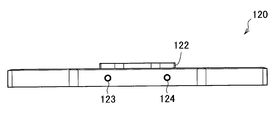
- FIG. 2A to 2D are explanatory views showing the appearance of the charging device 120 according to the embodiment of the present invention.
- 2A is a plan view of the charging device 120 according to one embodiment of the present invention
- FIG. 2B is a side view of the charging device 120 according to one embodiment of the present invention
- FIG. 2C is according to one embodiment of the present invention.
- FIG. 2D is a front view of the charging device 120
- FIG. 2D is a rear view of the charging device 120 according to the embodiment of the present invention.
- the charging device 120 according to the embodiment of the present invention has a substantially regular hexagonal shape.
- the charging device 120 according to the embodiment of the present invention has a substantially regular hexagonal hole 121 at the center of the plane, and a flat surface around the hole 121.
- the projection 122 protrudes by a predetermined height.
- the battery device 200 can be stably installed in the charging device 120 when the battery device 200 is placed on the charging device 120 and charged. Can do.
- the charging device 120 includes an input terminal 123 that can receive power and an output terminal 124 that can output power. .
- the charging device 120 receives from the input terminal 123 the power generated by the power plant 10, the power generated by the solar battery 20 receiving sunlight, and the power generated by the wind power generator 30 receiving wind power. It is received and supplied to the battery device 200.
- the positions of the input terminal 123 and the output terminal 124 are not limited to the illustrated positions.
- 3A to 3D are explanatory views showing another structure of the charging device 120 according to the embodiment of the present invention.
- 3A is a plan view of a charging device 120 ′ according to an embodiment of the present invention
- FIG. 3B is a side view of the charging device 120 ′ according to an embodiment of the present invention
- FIG. 3C is an embodiment of the present invention
- FIG. 3D is a bottom view of the charging device 120 ′ according to the embodiment of the present invention.
- the charging device 120 ′ has a shape that can be inserted into a hole 201 of the battery device 200 described later. Specifically, as shown in FIGS. 3A to 3D, the charging device 120 ′ is provided with an input terminal 123 ′ and an output terminal 124 ′ on the top of a columnar body 125 having a substantially regular hexagonal bottom surface.
- the engaging portion 126 has a substantially regular hexagonal shape larger than the substantially regular hexagonal shape on the bottom surface.
- the input terminal 123 ′ and the output terminal 124 ′ are terminals that can be supplied with power or output power, like the input terminal 123 and output terminal 124 described above.
- the non-contact power transmission / reception here refers to the one that moves electrical energy without physical contact by a connector or the like.
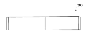
- FIG. 4A to 4C are explanatory views showing the structure of the battery device 200 according to the embodiment of the present invention.
- 4C is a plan view of the battery device 200 according to the embodiment of the present invention
- FIG. 4B is a side view of the battery device 200 according to the embodiment of the present invention
- FIG. 4C is according to the embodiment of the present invention.
- 3 is a front view of a battery device 200.
- the battery device 200 according to the embodiment of the present invention has a substantially regular hexagonal shape.
- the battery device 200 according to the embodiment of the present invention has a substantially regular hexagonal hole 201 in the center of the plane, and a guide around the hole 201. Part 202.
- the plane size of the battery device 200 is the same as the plane size of the charging device 120, and the battery device 200 can be superimposed on the charging device 120 while maintaining a regular hexagonal shape when viewed in a plane.
- the battery device 200 has such a size that the battery device 200 can include eighteen lithium ion secondary batteries connected in series and connected in parallel in eight rows.
- One size of the lithium ion battery is, for example, 26 mm in diameter and 65 mm in length.
- the battery device 200 has a circuit for supplying power to the lithium ion secondary battery, and receives power from the charging device 120 and releases power to the charging device 120. And a coil for wireless communication, a wireless communication means for performing wireless communication with the charging control device 110, and the like. Therefore, the size of the battery device 200 is desirably large enough to provide these circuits, coils, wireless communication means, and the like in addition to the lithium ion secondary battery.
- the guide part 202 can be swung up and down in the direction in which the substantially regular hexagonal hole 201 is vacant.
- the guide unit 202 protrudes from the plane of the battery device 200 by a predetermined height. Thereby, the battery device 200 can be stably stacked on the charging device 120. Further, the battery device 200 can be placed on the charging device 120 regardless of the front and back sides.
- the charging device 120 and the battery device 200 are formed on the outside with an integrally molded resin, for example, plastic. Since the charging device 120 and the battery device 200 are assumed to be used for a long time or carried outdoors, the outside of the charging device 120 and the battery device 200 is formed of a material having durability, waterproofness, and dustproofness. This is because it is desirable.
- the charging device 120 ′ is inserted into the hole 201 of the battery device 200, and power is transmitted and received in a non-contact manner between the charging device 120 ′ and the battery device 200 by the control from the charging control device 110. You can also
- the electric power stored in the secondary battery inside the battery device 200 may be taken out by non-contact power transmission and used, and a terminal (not shown) for outputting electric power to the battery device 200 is provided, Electric power may be taken out from the terminal and used.
- a handle 203 is formed on the side surface of the battery device 200. Since the handle 203 is formed on the side surface of the battery device 200, the battery device 200 can be easily carried. As shown in FIGS. 4A to 4C, the handle 203 may be provided as a pair on opposite side surfaces, or may be provided on at least one side surface.
- 5A to 5E are explanatory views showing the structure of the charging control device 110 according to the embodiment of the present invention.
- 5A is a plan view of the charge control device 110
- FIG. 5B is a front view of the charge control device 110
- FIG. 5C is a rear view of the charge control device 110
- FIG. 5D is a side view of the charge control device 110
- FIG. 5E is a bottom view of the charging control device 110.
- the charging control device 110 includes wireless communication means inside, and executes communication processing with respect to the charging device 120 and the battery device 200, so that the charging device 120 and the battery device 200 communicate with each other. Control charging between.
- the charging control device 110 has a substantially regular hexagonal plane.
- the charging control device 110 can be fitted into the hole 201 of the battery device 200 during the non-contact power feeding process between the charging device 120 and the battery device 200.
- FIG. 6 shows an installation example when performing non-contact power supply processing between the charging device 120 and the battery device 200.
- the battery device 200 is stacked on the charging device 120, and the hole 201 of the battery device 200 is stacked.
- It is explanatory drawing which illustrates the state which put the charging control apparatus 110 in.
- the charging control device 110 By installing the charging control device 110 in the hole 201, it is possible to control the non-contact power feeding between the charging device 120 and the battery device 200 in a space where the charging device 120 can be installed.
- FIG. 7 is an explanatory view showing an installation example when the non-contact power feeding process is executed between the charging device 120 ′ and the battery device 200, and the charging device 120 ′ is inserted into the hole 201 of the battery device 200. It is explanatory drawing which illustrated. Note that FIG. 7 does not show the charging control device 110.
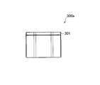
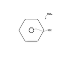
- FIG. 8 is an explanatory view showing the external appearance of the battery device 300a according to the embodiment of the present invention in a perspective view
- FIGS. 9A to 9D are respectively plan views of the battery device 300a according to the embodiment of the present invention. It is explanatory drawing which shows a front view, a side view, and a bottom view.
- the battery device 300a is a prism having a substantially regular hexagonal bottom surface. As will be described later, the battery device 300a is arranged on the charging device 120 or the battery device 200 so that non-contact power feeding from the charging device 120 is possible. Therefore, a power receiving means such as a coil is provided inside the battery device 300a so that power can be transmitted and received in a non-contact manner with the charging device 120 and the battery device 200.
- the battery device 300a is provided with a handle 301 for facilitating the carrying of the battery device 300a. Further, as shown in FIG. 9D, the battery device 300a is provided with a support member 302. The hole in which the support member 302 is provided can be fitted into a convex portion 401 of the charging tray 400 described later. When the battery device 300a is installed on the charging tray 400, the support member 302 becomes the upper surface of the battery device 300a. Projects to a predetermined height. With this support member 302, the battery devices 300a can be stacked or arranged side by side on the charging tray 400 described later.
- the power stored in the secondary battery inside the battery device 300a may be taken out by non-contact power transmission and used, and a terminal (not shown) for outputting power to the battery device 300a is provided, Electric power may be taken out from the terminal and used.
- the battery device 300a may be charged via the battery device 200.
- a later-described charging tray 400 may be placed on the battery device 200, and the battery device 300 a may be installed on the charging tray 400.
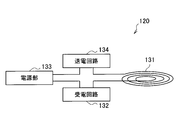
- FIG. 10 is an explanatory diagram showing a functional configuration of the charging device 120 according to the embodiment of the present invention.
- the functional configuration of the charging device 120 according to the embodiment of the present invention will be described with reference to FIG.
- the charging device 120 includes a coil 131, a power receiving circuit 132, a power supply unit 133, and a power transmission circuit 134.
- the coil 131 performs power transmission / reception in a non-contact manner with a coil at a distant position. Specifically, when the battery device 200 is placed on the charging device 120 and the charging process is started under the control of the charging control device 110, electric power is generated between the coil 131 and a coil 211 of the battery device 200 described later. Power transmission / reception is executed.
- the coil 131 can perform non-contact power transmission / reception between the coil 131 of the charging device 120 and the coil 211 of the battery device 200 regardless of how the battery device 200 is mounted on the charging device 120. Therefore, it is desirable that the battery device 200 is wound inside the charging device 120 so as to cover the entire surface on which the battery device 200 is placed, with the hollow portion of the charging device 120 as the center.
- the power reception circuit 132 is a circuit that performs non-contact power reception of power or detects the power received by the coil 131.
- the power receiving circuit 132 is provided with a capacitor having a predetermined capacity and a resistor having a predetermined resistance value in order to perform non-contact power reception.
- the power receiving circuit 132 supplies the power received by the coil 131 to the power supply unit 133 when the battery device 200 is placed on the charging device 120 and a charging process is performed under the control of the charging control device 110.
- the power receiving circuit 132 detects that the amount of power stored in the power supply unit 133 has reached a predetermined amount, the power receiving circuit 132 stops supplying the power received by the coil 131 to the power supply unit 133.
- the power supply unit 133 stores power to be supplied to the battery device 200 through the power transmission circuit 134 and the coil 131.
- the power supply unit 133 may supply power supplied from the outside of the charging device 120 to the battery device 200 through the power transmission circuit 134 and the coil 131, and a battery having a certain capacity is provided inside. May be.
- the power transmission circuit 134 outputs power from the power supply unit 133 to the coil 131 in order to supply power to the battery device 200.
- the power transmission circuit 134 is provided with a capacitor having a predetermined capacity and a resistor having a predetermined resistance value in order to perform non-contact power transmission of electric power.
- FIG. 11 is an explanatory diagram showing a functional configuration of the battery device 200 according to the embodiment of the present invention.
- the functional configuration of the battery device 200 according to the embodiment of the present invention will be described with reference to FIG.
- the battery device 200 includes a coil 211, a power receiving circuit 212, a power storage unit 213, and a power transmission circuit 214.
- the coil 211 performs power transmission / reception in a non-contact manner with a coil at a distant position. Specifically, when the battery device 200 is placed on the charging device 120 and the charging process is started under the control of the charging control device 110, power is transmitted and received between the coil 211 and the coil 131 of the charging device 120. Is executed.
- the power receiving circuit 212 is a circuit that performs non-contact power reception of power or detects the power received by the coil 211. Although not shown, the power receiving circuit 212 is provided with a capacitor having a predetermined capacity and a resistor having a predetermined resistance value in order to perform non-contact power reception. The power receiving circuit 212 supplies the power received by the coil 211 to the power storage unit 213 when the battery device 200 is placed on the charging device 120 and a charging process is performed under the control of the charging control device 110. When the power reception circuit 212 detects that the amount of power stored in the power storage unit 213 has reached a predetermined amount, the power reception circuit 212 stops supplying the power received by the coil 211 to the power storage unit 213.
- the power storage unit 213 stores power received by the coil 211 and supplied from the power receiving circuit 212.
- the power stored in the power storage unit 213 can be supplied to the outside through the power transmission circuit 214 and the coil 211. Therefore, the power storage unit 213 may include a secondary battery having a predetermined capacity.
- the power transmission circuit 214 outputs power from the power storage unit 213 to the coil 211 in order to supply power from the coil 211 to the outside (for example, the charging device 120).
- the power transmission circuit 214 is provided with a capacitor having a predetermined capacity and a resistor having a predetermined resistance value in order to perform non-contact power transmission of electric power.
- FIGS. 12A to 12C are explanatory diagrams showing an outline of the non-contact power transmission / reception process of power between the charging device 120 and the battery device 200 according to the embodiment of the present invention.
- FIG. 12A to FIG. 12C three battery devices 200 are placed on top of the charging device 120, and power is not transferred between the charging device 120 and the three battery devices 200 under the control of the charging control device 110. The case where contact power transmission / reception processing is performed is illustrated.
- a non-contact power transmission / reception process between the charging device 120 and the battery device 200 according to the embodiment of the present invention will be described with reference to FIGS. 12A to 12C.
- the three battery devices 200 will be described as battery devices 200a, 200b, and 200c in order from the one placed below.
- FIGS. 12A to 12C show an operation when non-contact power transmission is performed from the charging device 120 to the battery device 200 under the control of the charging control device 110.
- the charging control device 110 performs communication between the charging device 120 and the battery device 200, and executes initial setting for collecting information on the charging device 120 and the battery device 200.
- This initial setting may include acquisition of the number of battery devices 200 stacked on the charging device 120, designation of the order of the battery devices 200 that perform charging, and the like.
- Each charging device 120 may be assigned an identification number, and the charging device 120 may include a storage unit such as a memory, and the storage unit may store the identification number of the charging device 120. .
- each battery device 200 may be assigned an identification number so that each battery device 200 can be individually identified.
- Storage means such as a memory may be provided, and the identification number of the battery device 200 may be held in the storage means.
- the identification number held in the charging device 120 or the battery device 200 may be transmitted to the charging control device 110.
- the charging control device 110 By transmitting the identification number from the charging device 120 or the battery device 200 to the charging control device 110, how much power the charging device 120 has output for charging the battery device 200, and how much power the battery device 200 has.
- the charge control device 110 can be made aware of whether or not it has been used.
- the charging control device 110 grasps the power usage status of each charging device 120 or the battery device 200, the charging control device 110 determines, for example, which battery device 200 is preferentially charged, It is possible to grasp the amount of power used necessary for the charging process for the user of the battery device 200.
- the charging device 120 When the charging control device 110 completes the initial setting, the charging device 120 subsequently performs non-contact power transmission of power to the battery device 200a placed at the bottom.
- the power transmission circuit 134 of the charging device 120 is activated, and the power from the power supply unit 133 is transmitted to the battery device 200 a placed at the lowest level through the coil 131. .
- Battery device 200 a that has received power that is contactlessly transmitted from charging device 120 by means of coil 211 sends the power to power storage unit 213 through power reception circuit 212. Thereby, the power storage unit 213 of the battery device 200a can store therein the electric power transmitted from the charging device 120 in a contactless manner.
- the battery device 200a transmits a charging completion notification notifying that the charging has been completed to the charging control device 110.
- the charging control device 110 Upon receiving the charge completion notification from the battery device 200a, the charging control device 110 notifies the charging device 120 to switch the power transmission destination from the battery device 200a to the battery device 200b.
- the power transmission circuit 134 of the charging device 120 is activated, and the power from the power supply unit 133 is placed second through the coil 131 from the bottom. The power is transmitted to the battery device 200b.
- Battery device 200 b that has received power that is contactlessly transmitted from charging device 120 by coil 211 sends the power to power storage unit 213 through power reception circuit 212. Thereby, the power storage unit 213 of the battery device 200b can store the electric power transmitted from the charging device 120 in a contactless manner.
- the battery device 200b transmits a charge completion notification notifying that the charging has been completed to the charge control device 110.
- the charging control device 110 Upon receiving the charging completion notification from the battery device 200b, the charging control device 110 notifies the charging device 120 to switch the power transmission destination from the battery device 200b to the battery device 200c.
- the power transmission circuit 134 of the charging device 120 is activated, and the power from the power supply unit 133 is placed on the top through the coil 131. Power is transmitted to the existing battery device 200c.
- Battery device 200c that has received power that is contactlessly transmitted from charging device 120 by coil 211 sends the power to power storage unit 213 by power receiving circuit 212. Thereby, the electrical storage part 213 of the battery apparatus 200c can store the electric power transmitted non-contactly from the charging device 120 inside.
- the charging device 120 selectively transmits power to the plurality of battery devices 200. Can be switched.
- the charging device 120 can employ a method of changing a frequency used in contactless power transmission.
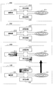
- FIGS. 13A to 13C are explanatory diagrams showing an outline of the non-contact power transmission / reception process of power between the charging device 120 and the battery device 200 according to the embodiment of the present invention.
- FIG. 13A to FIG. 13C three battery devices 200 are placed on top of the charging device 120, and non-contact power transmission processing of power from the three battery devices 200 to the charging device 120 is performed under the control of the charging control device 110. The case where it is done is illustrated.
- a non-contact power transmission / reception process between the charging device 120 and the battery device 200 according to an embodiment of the present invention will be described with reference to FIGS. 13A to 13C.
- the three battery devices 200 will be described as battery devices 200a, 200b, and 200c in order from the one placed below.
- FIGS. 13A to 13C show an operation when non-contact power transmission is performed from the battery device 200 to the charging device 120 under the control of the charging control device 110.
- the charging control device 110 performs communication between the charging device 120 and the battery device 200, and executes initial setting for collecting information on the charging device 120 and the battery device 200.
- This initial setting may include acquisition of the number of battery devices 200 stacked on the charging device 120, designation of the order of the battery devices 200 that perform power transmission, and the like.
- Each charging device 120 may be assigned an identification number, and the charging device 120 may include a storage unit such as a memory, and the storage unit may store the identification number of the charging device 120. .
- each battery device 200 may be assigned an identification number so that each battery device 200 can be individually identified.
- Storage means such as a memory may be provided, and the identification number of the battery device 200 may be held in the storage means.
- the identification number held in the charging device 120 or the battery device 200 may be transmitted to the charging control device 110.
- the charging control device 110 By transmitting the identification number from the charging device 120 or the battery device 200 to the charging control device 110, how much power the battery device 200 has output for charging the charging device 120, and how much power the battery device 200 has.
- the charge control device 110 can be made aware of whether or not it has been used.
- the charging control device 110 grasps the power usage status of each charging device 120 or the battery device 200, the charging control device 110 determines, for example, from which battery device 200 the power transmission is preferentially performed, It is possible to grasp the amount of power used for the refund process for the user of the battery device 200.
- the battery device 200a placed at the bottom performs non-contact power transmission of power to the charging device 120.
- the power transmission circuit 214 of the battery device 200a operates, and the power from the power storage unit 213 is transmitted to the charging device 120 through the coil 211.
- the charging device 120 that has received power that is contactlessly transmitted from the battery device 200 a by the coil 131 sends the power to the power supply unit 133 by the power receiving circuit 132. Thereby, the power supply part 133 of the charging device 120 can store the electric power transmitted in a non-contact manner from the battery device 200a inside or discharge the electric power to the outside of the charging device 120.
- the battery device 200a When the power transmission circuit 214 of the battery device 200a detects that the discharge from the power storage unit 213 has been completed or that the power stored in the power storage unit 213 has become a predetermined amount or less, the battery device 200a has completed power transmission. A power transmission completion notification is sent to the charging control device 110 to notify this. Upon receiving the power transmission completion notification from the battery device 200a, the charging control device 110 notifies the battery device 200b to transmit power to the charging device 120.
- the power transmission circuit 214 of the battery device 200b Upon receiving the power transmission instruction notification from the charging control device 110, the power transmission circuit 214 of the battery device 200b operates, and the battery device 200b transmits the power from the power storage unit 213 to the charging device 120 through the coil 211.
- the charging device 120 that has received power that is contactlessly transmitted from the battery device 200 b by the coil 131 sends the power to the power supply unit 133 by the power receiving circuit 132.
- the power supply part 133 of the charging device 120 can store the electric power transmitted in a non-contact manner from the battery device 200b inside or can release the electric power to the outside of the charging device 120.
- the battery device 200b When the power transmission circuit 214 of the battery device 200b detects that the discharge from the power storage unit 213 has been completed or that the power stored in the power storage unit 213 has become a predetermined amount or less, the battery device 200b has completed power transmission. A power transmission completion notification is sent to the charging control device 110 to notify this. Upon receiving the power transmission completion notification from the battery device 200b, the charging control device 110 notifies the battery device 200c to transmit power to the charging device 120.
- the power transmission circuit 214 of the battery device 200c Upon receiving the power transmission instruction notification from the charge control device 110, the power transmission circuit 214 of the battery device 200c operates, and the battery device 200c transmits the power from the power storage unit 213 to the charging device 120 through the coil 211.
- the charging device 120 that has received power that is contactlessly transmitted from the battery device 200 c by the coil 131 sends the power to the power supply unit 133 by the power receiving circuit 132. Thereby, the power supply part 133 of the charging device 120 can store the electric power transmitted in a non-contact manner from the battery device 200c inside or discharge the electric power to the outside of the charging device 120.
- the charging device 120 selectively contacts the power from the plurality of battery devices 200. Can receive power.
- the charging device 120 can adopt a method of changing a frequency used in the case of non-contact power transmission.
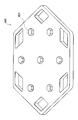
- FIG. 14 is an explanatory diagram showing an appearance of the charging tray 400 for installing the battery device 300a when charging the battery device 300a according to the embodiment of the present invention.
- FIG. 15 is explanatory drawing which shows the state which installs the battery apparatus 300a in the charge tray 400, and charges the battery apparatus 300a.
- the charging tray 400 shown in FIG. 14 is provided with seven convex portions 401 as shown in the figure, and when the supporting member 302 of the battery device 300a shown in FIG. The height protrudes. Thereby, the battery apparatus 300a can be stably installed on the charging tray.
- the charging tray 400 shown in FIG. 14 has a substantially regular hexagonal shape that is the same as that of the charging device 120 and the battery device 200.
- the plane size of the charging tray 400 is the same as that of the charging device 120 and the battery device 200. Therefore, by charging the charging tray 400 on the charging device 120 or the battery device 200, the battery device 300a installed on the charging tray 400 can be charged if the charging device 120 is large enough to be installed.
- the battery device 300a may be charged via the battery device 200.
- a later-described charging tray 400 may be placed on the battery device 200, and the battery device 300 a may be installed on the charging tray 400.
- the power for charging the battery device 300 a placed on the charging tray 400 may be supplied directly from the charging device 120 or may be supplied from the battery device 200.
- the electric power once stored in the battery device 200 can be subdivided into the battery device 300a.
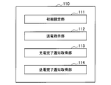
- FIG. 16 is an explanatory diagram showing a functional configuration of the charging control apparatus 110 according to the embodiment of the present invention.
- the functional configuration of the charging control apparatus 110 according to the embodiment of the present invention will be described with reference to FIG.
- the charging control device 110 includes an initial setting unit 111, a power transmission instruction unit 112, a charging completion notification acquisition unit 113, and a power transmission completion notification acquisition unit 114.
- the initial setting unit 111 performs an initial setting for a plurality of battery devices (for example, the battery device 200) including secondary batteries therein and a charging device 120 that performs non-contact power transmission to the battery devices that are stacked and installed. Execute.
- the charging completion notification acquisition unit 113 acquires a charging completion notification from the battery device 200 that has been charged. After the charging completion notification acquisition unit 113 acquires the completion notification, the power transmission instruction unit 112 instructs the charging device 120 to start non-contact power transmission to a battery device different from the battery device that has previously instructed power transmission. .
- the power transmission completion notification acquisition unit 114 acquires a power transmission completion notification transmitted from the battery device 200 when the voltage of the secondary battery included in the battery device 200 becomes a predetermined value or less. After the power transmission completion notification acquisition unit 114 acquires the completion notification, the power transmission instruction unit 112 instructs a battery device different from the battery device that has previously instructed power transmission to start non-contact power transmission to the charging device 120. .
- FIG. 17 is a flowchart showing an outline of the operation of the power supply system 1 according to the embodiment of the present invention.
- the charging control device 110 is first activated (step S11).
- the activated charge control device 110 confirms information of the battery device 200 (step S12), and determines whether there is a battery device 200 that can be charged (step S13). If there is no rechargeable battery device 200, the process ends.
- the charging control device 110 determines the charging order of the battery device 200 (step S14).
- the charging order of the battery device 200 can be arbitrarily determined.
- the charging control device 110 may determine the charging order of the battery device 200 so that the battery device 200 is charged from the one with the smaller charge amount, or conversely, the charge order of the battery device 200 may be charged from the one with the larger charge amount. Good.
- the determination of the charging order of the battery device 200 is not limited to this example.
- the charging control device 110 determines the charging order of the battery device 200
- the charging control device 110 instructs the charging device 120 to transmit power to the battery device 200 in accordance with the determined order (step S15). Then, the charging control device 110 determines whether or not the charging device 120 has completed power transmission to the battery device 200 (step S16), and if not completed, continues power transmission to the battery device 200. Return to step S13. This series of processing is continued until there is no battery device 200 that can be charged.
- FIG. 18 is a flowchart showing the operation of the power supply system 1 according to the embodiment of the present invention.
- two battery devices 200 a and 200 b are illustrated for convenience in order to explain the operation of the power supply system 1.
- operation movement of the electric power supply system 1 concerning one Embodiment of this invention is demonstrated using FIG.
- Charging control device 110 performs initial settings for a plurality of battery devices (for example, battery device 200) including secondary batteries therein and charging device 120 that performs non-contact power transmission to battery devices that are stacked and installed. Execute (Steps S101, S102, S103). This initial setting process is executed by, for example, the initial setting unit 111.
- the initial setting may include, for example, confirmation of information on battery devices stacked and installed, confirmation of information on battery devices that can be charged, and determination of the order of charging.
- the charging control device 110 then instructs the battery device 200a from the charging device 120 that has completed the initial setting to start non-contact power transmission (step S104).
- the power transmission instruction unit 112 executes this contactless power transmission start instruction. Receiving the instruction to start contactless power transmission, charging device 120 starts contactless power transmission to battery device 200a (step S105).
- Battery device 200a transmits a charging completion notification to charging control device 110 when charging is completed by non-contact power transmission from charging device 120 (step S106).
- the charging completion notification from the battery device 200a is acquired by the charging completion notification acquisition unit 113, for example.
- the charging control device 110 acquires the charging completion notification from the battery device 200a
- the charging device 120 instructs the battery device 200b to start non-contact power transmission (step S107).
- the power transmission instruction unit 112 executes this contactless power transmission start instruction. Receiving the instruction to start contactless power transmission, charging device 120 starts contactless power transmission to battery device 200b (step S108).
- Battery device 200b transmits a charging completion notification to charging control device 110 when charging is completed by non-contact power transmission from charging device 120 (step S109).
- the charging completion notification from the battery device 200b is acquired by the charging completion notification acquisition unit 113, for example.
- the charging control device 110 repeats from the transmission of the power transmission instruction to the acquisition of the charging completion notification until the charging of all the battery devices that have been initially set is completed.
- FIG. 19 is a flowchart showing the operation of the power supply system 1 according to the embodiment of the present invention.
- two battery devices 200 a and 200 b are illustrated for convenience in explaining the operation of the power supply system 1.
- operation movement of the electric power supply system 1 concerning one Embodiment of this invention is demonstrated using FIG.
- Charging control device 110 performs initial settings for a plurality of battery devices (for example, battery device 200) including secondary batteries therein and charging device 120 that performs non-contact power transmission to battery devices that are stacked and installed. Execute (Steps S111, S112, S113). This initial setting process is executed by, for example, the initial setting unit 111.
- the initial setting may include, for example, confirmation of information on battery devices stacked and installed, confirmation of information on battery devices capable of power transmission, and determination of the order of power transmission.
- the charging control device 110 then instructs the charging device 120 to start non-contact power transmission from the battery device 200a that has completed the initial setting (step S114).
- the power transmission instruction unit 112 executes this contactless power transmission start instruction. Receiving the contactless power transmission start instruction, the battery device 200a starts contactless power transmission to the charging device 120 (step S115).
- Battery device 200a transmits a power transmission completion notification to charging control device 110 when the voltage of the internal secondary battery becomes a predetermined value or less by non-contact power transmission to charging device 120 (step S116).
- the power transmission completion notification acquisition unit 114 acquires the power transmission completion notification from the battery device 200a.
- the charging control device 110 instructs the charging device 120 to start non-contact power transmission from the battery device 200b (step S117).
- the power transmission instruction unit 112 executes this contactless power transmission start instruction. Receiving the instruction to start contactless power transmission, battery device 200b starts contactless power transmission to charging device 120 (step S118).
- Battery device 200b transmits a power transmission completion notification to charging control device 110 when the voltage of the internal secondary battery becomes a predetermined value or less by non-contact power transmission from charging device 120 (step S119).
- the charging completion notification from the battery device 200b is acquired by the charging completion notification acquisition unit 113, for example.
- the charging control device 110 repeats from transmission of a power transmission instruction to acquisition of a power transmission completion notification until power transmission of all the battery devices that have been initially set is completed.
- the advertising content by video is stored in the battery device 200 together with the electric power so that the advertising content is displayed when the television is used. May be.
- the radio or portable music player or the like is operated by the electric power stored in the battery device 300a
- the advertisement content by voice is stored in the battery device 300a together with the electric power, and the radio or portable music player or the like is stored.
- the advertisement content may be output when used.
- a charging device can be configured by arranging a plurality of charging devices 120 having a substantially regular hexagonal planar shape, and a charging device having a shape in which a plurality of charging devices 120 having a substantially regular hexagonal planar shape are combined is configured. You can also
- the battery device 200 is superposed on the charging device 120 and installed from the charging device 120 under the control of the charging control device 110. Non-contact power feeding is performed to the battery 200, and the secondary battery provided in the battery device 200 can be charged.
- the power supply system 1 By configuring the power supply system 1 in this way, the user can use electrical energy when he / she wants to use it. Further, the power supply system 1 can be easily increased and decreased, and further, it is not necessary to stretch the electric wire, so that the initial infrastructure investment can be reduced.
- the charging device 120 It is possible to install a plurality of battery devices 200 on the charging device 120. Therefore, according to an embodiment of the present invention, it is possible to perform non-contact power feeding from the charging device 120 to the plurality of battery devices 200 in a state where the plurality of battery devices 200 are stacked on the charging device 120. In that case, the non-contact electric power feeding to the some battery apparatus 200 can be performed by switching the electric power feeding destination of the charging device 120 one by one by control of the charging control apparatus 110.
- the bottom surfaces of the charging device 120 and the battery device 200 are substantially regular hexagons having the same size and are columnar bodies each having a predetermined height.
- the present invention is not limited to such an example.
- the bottom surface of the charging device 120 may have a larger regular hexagon than the bottom surface of the battery device 200, and vice versa.
Landscapes
- Engineering & Computer Science (AREA)
- Power Engineering (AREA)
- Computer Networks & Wireless Communication (AREA)
- Manufacturing & Machinery (AREA)
- Chemical & Material Sciences (AREA)
- Chemical Kinetics & Catalysis (AREA)
- Electrochemistry (AREA)
- General Chemical & Material Sciences (AREA)
- Microelectronics & Electronic Packaging (AREA)
- Charge And Discharge Circuits For Batteries Or The Like (AREA)
- Secondary Cells (AREA)
Priority Applications (4)
| Application Number | Priority Date | Filing Date | Title |
|---|---|---|---|
| JP2012533953A JP6011338B2 (ja) | 2010-09-17 | 2011-09-06 | 電力供給方法、充電制御装置及び電力供給システム |
| CN201180043346.4A CN103098332B (zh) | 2010-09-17 | 2011-09-06 | 电力供给方法、充电控制装置和电力供给系统 |
| US13/824,102 US20140361734A1 (en) | 2010-09-17 | 2011-09-06 | Power supply method, charging control device, and power supply system |
| EP11825030.7A EP2618447B1 (de) | 2010-09-17 | 2011-09-06 | Stromversorgungsverfahren, ladesteuerungsvorrichtung und stromversorgungssystem |
Applications Claiming Priority (2)
| Application Number | Priority Date | Filing Date | Title |
|---|---|---|---|
| JP2010-209771 | 2010-09-17 | ||
| JP2010209771 | 2010-09-17 |
Publications (1)
| Publication Number | Publication Date |
|---|---|
| WO2012036024A1 true WO2012036024A1 (ja) | 2012-03-22 |
Family
ID=45831491
Family Applications (1)
| Application Number | Title | Priority Date | Filing Date |
|---|---|---|---|
| PCT/JP2011/070263 WO2012036024A1 (ja) | 2010-09-17 | 2011-09-06 | 電力供給方法、充電制御装置及び電力供給システム |
Country Status (5)
| Country | Link |
|---|---|
| US (1) | US20140361734A1 (de) |
| EP (1) | EP2618447B1 (de) |
| JP (1) | JP6011338B2 (de) |
| CN (1) | CN103098332B (de) |
| WO (1) | WO2012036024A1 (de) |
Cited By (4)
| Publication number | Priority date | Publication date | Assignee | Title |
|---|---|---|---|---|
| CN102759652A (zh) * | 2012-06-28 | 2012-10-31 | 河南省电力公司信阳供电公司 | 太阳能高压带电显示装置 |
| JP2015119572A (ja) * | 2013-12-19 | 2015-06-25 | カシオ計算機株式会社 | 電子機器及びプログラム |
| WO2017094386A1 (ja) * | 2015-11-30 | 2017-06-08 | オムロン株式会社 | 非接触給電システム |
| WO2017204130A1 (ja) * | 2016-05-24 | 2017-11-30 | パナソニックIpマネジメント株式会社 | 充電システム |
Families Citing this family (5)
| Publication number | Priority date | Publication date | Assignee | Title |
|---|---|---|---|---|
| JP5691337B2 (ja) * | 2010-09-17 | 2015-04-01 | ソニー株式会社 | 電力供給システム、充電制御装置及びバッテリ装置 |
| JP6322979B2 (ja) * | 2012-12-28 | 2018-05-16 | 株式会社リコー | 充電装置及び充電システム |
| DE102015117978A1 (de) * | 2015-10-22 | 2017-04-27 | Rwe Ag | Mobiler elektrischer Speicher |
| WO2019059917A1 (en) | 2017-09-22 | 2019-03-28 | Hewlett-Packard Development Company, L.P. | CHARGING STACKABLE DEVICES |
| US20220178530A1 (en) * | 2019-03-28 | 2022-06-09 | Aoi Japan Co., Ltd. | Wireless power feeding system having battery mounted device engaged with power receiving device with light unit mounted device |
Citations (3)
| Publication number | Priority date | Publication date | Assignee | Title |
|---|---|---|---|---|
| JP2008017592A (ja) * | 2006-07-05 | 2008-01-24 | Ricoh Elemex Corp | 情報表示システム装置 |
| JP2010084425A (ja) * | 2008-09-30 | 2010-04-15 | Saxa Inc | パイロン及びパイロン用充電台 |
| JP2010183706A (ja) * | 2009-02-04 | 2010-08-19 | Sanyo Electric Co Ltd | 充電台 |
Family Cites Families (16)
| Publication number | Priority date | Publication date | Assignee | Title |
|---|---|---|---|---|
| US4849682A (en) * | 1987-10-30 | 1989-07-18 | Anton/Bauer, Inc. | Battery charging system |
| JP3430466B2 (ja) * | 1994-04-28 | 2003-07-28 | ローム株式会社 | 二次電池の充電装置 |
| CN1044954C (zh) * | 1995-02-20 | 1999-09-01 | 三洋电机株式会社 | 向电子器具供电的电源装置 |
| US5814968A (en) * | 1995-06-26 | 1998-09-29 | Long Range Systems, Inc. | Battery charger and rechargeable electronic paging device assembly |
| JP3363341B2 (ja) * | 1997-03-26 | 2003-01-08 | 松下電工株式会社 | 非接触電力伝達装置 |
| US7282889B2 (en) * | 2001-04-19 | 2007-10-16 | Onwafer Technologies, Inc. | Maintenance unit for a sensor apparatus |
| US8183827B2 (en) * | 2003-01-28 | 2012-05-22 | Hewlett-Packard Development Company, L.P. | Adaptive charger system and method |
| BRPI0508587A (pt) * | 2004-03-08 | 2007-08-21 | Beghelli Spa | dispositivo recarregador de bateria |
| KR100736053B1 (ko) * | 2005-10-24 | 2007-07-06 | 삼성전자주식회사 | 유도 방식에 의해 무선으로 전원을 공유하는 장치 및 방법 |
| US20070236174A1 (en) * | 2006-04-09 | 2007-10-11 | Evan John Kaye | Point-Of-Sale Non-Contact Charging |
| US8193764B2 (en) * | 2007-08-08 | 2012-06-05 | Jay Marketing Associates, Inc. | Wireless charging of electronic devices |
| JP5209391B2 (ja) * | 2008-07-09 | 2013-06-12 | 富士フイルム株式会社 | 充電装置 |
| WO2010062201A1 (en) * | 2008-11-26 | 2010-06-03 | Auckland Uniservices Limited | Primary-side power control for inductive power transfer |
| EP2382715A4 (de) * | 2009-01-22 | 2012-08-29 | Techtronic Power Tools Tech | Drahtloses leistungsverteilungssystem und -verfahren für elektrowerkzeuge |
| WO2010116441A1 (ja) * | 2009-03-30 | 2010-10-14 | 富士通株式会社 | 無線電力供給システム、無線送電装置、および無線受電装置 |
| JP5691337B2 (ja) * | 2010-09-17 | 2015-04-01 | ソニー株式会社 | 電力供給システム、充電制御装置及びバッテリ装置 |
-
2011
- 2011-09-06 CN CN201180043346.4A patent/CN103098332B/zh not_active Expired - Fee Related
- 2011-09-06 US US13/824,102 patent/US20140361734A1/en not_active Abandoned
- 2011-09-06 WO PCT/JP2011/070263 patent/WO2012036024A1/ja active Application Filing
- 2011-09-06 EP EP11825030.7A patent/EP2618447B1/de not_active Not-in-force
- 2011-09-06 JP JP2012533953A patent/JP6011338B2/ja not_active Expired - Fee Related
Patent Citations (3)
| Publication number | Priority date | Publication date | Assignee | Title |
|---|---|---|---|---|
| JP2008017592A (ja) * | 2006-07-05 | 2008-01-24 | Ricoh Elemex Corp | 情報表示システム装置 |
| JP2010084425A (ja) * | 2008-09-30 | 2010-04-15 | Saxa Inc | パイロン及びパイロン用充電台 |
| JP2010183706A (ja) * | 2009-02-04 | 2010-08-19 | Sanyo Electric Co Ltd | 充電台 |
Non-Patent Citations (1)
| Title |
|---|
| See also references of EP2618447A4 * |
Cited By (7)
| Publication number | Priority date | Publication date | Assignee | Title |
|---|---|---|---|---|
| CN102759652A (zh) * | 2012-06-28 | 2012-10-31 | 河南省电力公司信阳供电公司 | 太阳能高压带电显示装置 |
| JP2015119572A (ja) * | 2013-12-19 | 2015-06-25 | カシオ計算機株式会社 | 電子機器及びプログラム |
| WO2017094386A1 (ja) * | 2015-11-30 | 2017-06-08 | オムロン株式会社 | 非接触給電システム |
| US10637297B2 (en) | 2015-11-30 | 2020-04-28 | Omron Corporation | Non-contact power feeding system |
| WO2017204130A1 (ja) * | 2016-05-24 | 2017-11-30 | パナソニックIpマネジメント株式会社 | 充電システム |
| JPWO2017204130A1 (ja) * | 2016-05-24 | 2019-03-14 | パナソニックIpマネジメント株式会社 | 充電システム |
| US10574078B2 (en) | 2016-05-24 | 2020-02-25 | Panasonic Intellectual Property Management Co., Ltd. | Charging system |
Also Published As
| Publication number | Publication date |
|---|---|
| US20140361734A1 (en) | 2014-12-11 |
| CN103098332B (zh) | 2016-08-03 |
| JPWO2012036024A1 (ja) | 2014-02-03 |
| EP2618447A1 (de) | 2013-07-24 |
| CN103098332A (zh) | 2013-05-08 |
| JP6011338B2 (ja) | 2016-10-19 |
| EP2618447A4 (de) | 2014-07-23 |
| EP2618447B1 (de) | 2016-11-02 |
Similar Documents
| Publication | Publication Date | Title |
|---|---|---|
| JP6011338B2 (ja) | 電力供給方法、充電制御装置及び電力供給システム | |
| KR100792308B1 (ko) | 코일 어레이를 구비한 무접점 충전장치, 무접점 충전시스템 및 충전 방법 | |
| CN102792555B (zh) | 无线功率充电方法和装置 | |
| CN104756358B (zh) | 无线电力接收器和用于在无线电力接收器中设定睡眠模式的方法 | |
| KR101897543B1 (ko) | 무선 전력 수신기 및 그 제어 방법 | |
| CN103988393B (zh) | 发送无线电力的装置和方法 | |
| CN103259297B (zh) | 无线充电控制方法和无线充电装置 | |
| WO2015137815A1 (en) | Arrangement of an electronic cigarette and a charger for wirelessly transferring power from the charger to the electronic cigarette, as well as an electronic cigarette and a charger for use in such an arrangement | |
| KR20130098958A (ko) | 무선 전력 송신기 및 무선 전력 수신기와 각각의 제어 방법 | |
| US10790710B2 (en) | Power feeding unit, power feeding system, and electronic unit | |
| JP5691337B2 (ja) | 電力供給システム、充電制御装置及びバッテリ装置 | |
| CN108702031A (zh) | 具有多个发送线圈的无线电力装置及其驱动方法 | |
| CN109155526A (zh) | 无线可再充电蓄能器 | |
| KR101375637B1 (ko) | 무선 전력 전송을 위한 능동형 에너지 중계기 및 이를 이용한 무선 전력 전송 방법 및 시스템 | |
| CN201584823U (zh) | 一种无线供电装置 | |
| CN106450911A (zh) | 一种插座可活动的插排 | |
| KR20140117185A (ko) | 재충전 모듈을 구비한 무선 충전 장치 및 유무선 복합 충전 시스템 | |
| CN205231777U (zh) | 一种具有充电功能的包 | |
| CN107612090A (zh) | 移动式无线万能充电器 | |
| US11264836B2 (en) | Wireless kinetic charger | |
| CN201478413U (zh) | 一种无线充电电池 | |
| CN102005622A (zh) | 一种无线充电电池 | |
| Rangari | Wireless Power Transmission | |
| KR20210108000A (ko) | 마이크로그리드 무선전력 코드리스 테스트베드 시스템 | |
| TWM415524U (en) | Wireless-charging type mobile communication device, antenna device having integrated charging function, and wireless charging system |
Legal Events
| Date | Code | Title | Description |
|---|---|---|---|
| WWE | Wipo information: entry into national phase |
Ref document number: 201180043346.4 Country of ref document: CN |
|
| 121 | Ep: the epo has been informed by wipo that ep was designated in this application |
Ref document number: 11825030 Country of ref document: EP Kind code of ref document: A1 |
|
| REEP | Request for entry into the european phase |
Ref document number: 2011825030 Country of ref document: EP |
|
| WWE | Wipo information: entry into national phase |
Ref document number: 2011825030 Country of ref document: EP |
|
| ENP | Entry into the national phase |
Ref document number: 2012533953 Country of ref document: JP Kind code of ref document: A |
|
| NENP | Non-entry into the national phase |
Ref country code: DE |
|
| WWE | Wipo information: entry into national phase |
Ref document number: 13824102 Country of ref document: US |