WO2012035896A1 - 導光板、照明装置、液晶表示装置、および、テレビジョン受信機 - Google Patents
導光板、照明装置、液晶表示装置、および、テレビジョン受信機 Download PDFInfo
- Publication number
- WO2012035896A1 WO2012035896A1 PCT/JP2011/067305 JP2011067305W WO2012035896A1 WO 2012035896 A1 WO2012035896 A1 WO 2012035896A1 JP 2011067305 W JP2011067305 W JP 2011067305W WO 2012035896 A1 WO2012035896 A1 WO 2012035896A1
- Authority
- WO
- WIPO (PCT)
- Prior art keywords
- light guide
- light
- guide plate
- support portion
- liquid crystal
- Prior art date
- Legal status (The legal status is an assumption and is not a legal conclusion. Google has not performed a legal analysis and makes no representation as to the accuracy of the status listed.)
- Ceased
Links
Images






Classifications
-
- G—PHYSICS
- G02—OPTICS
- G02B—OPTICAL ELEMENTS, SYSTEMS OR APPARATUS
- G02B6/00—Light guides; Structural details of arrangements comprising light guides and other optical elements, e.g. couplings
- G02B6/0001—Light guides; Structural details of arrangements comprising light guides and other optical elements, e.g. couplings specially adapted for lighting devices or systems
- G02B6/0011—Light guides; Structural details of arrangements comprising light guides and other optical elements, e.g. couplings specially adapted for lighting devices or systems the light guides being planar or of plate-like form
- G02B6/0081—Mechanical or electrical aspects of the light guide and light source in the lighting device peculiar to the adaptation to planar light guides, e.g. concerning packaging
- G02B6/0086—Positioning aspects
- G02B6/0088—Positioning aspects of the light guide or other optical sheets in the package
-
- H—ELECTRICITY
- H04—ELECTRIC COMMUNICATION TECHNIQUE
- H04N—PICTORIAL COMMUNICATION, e.g. TELEVISION
- H04N5/00—Details of television systems
- H04N5/64—Constructional details of receivers, e.g. cabinets or dust covers
- H04N5/655—Construction or mounting of chassis, e.g. for varying the elevation of the tube
-
- G—PHYSICS
- G02—OPTICS
- G02B—OPTICAL ELEMENTS, SYSTEMS OR APPARATUS
- G02B6/00—Light guides; Structural details of arrangements comprising light guides and other optical elements, e.g. couplings
- G02B6/0001—Light guides; Structural details of arrangements comprising light guides and other optical elements, e.g. couplings specially adapted for lighting devices or systems
- G02B6/0011—Light guides; Structural details of arrangements comprising light guides and other optical elements, e.g. couplings specially adapted for lighting devices or systems the light guides being planar or of plate-like form
- G02B6/0033—Means for improving the coupling-out of light from the light guide
- G02B6/0035—Means for improving the coupling-out of light from the light guide provided on the surface of the light guide or in the bulk of it
- G02B6/004—Scattering dots or dot-like elements, e.g. microbeads, scattering particles, nanoparticles
- G02B6/0043—Scattering dots or dot-like elements, e.g. microbeads, scattering particles, nanoparticles provided on the surface of the light guide
-
- G—PHYSICS
- G02—OPTICS
- G02F—OPTICAL DEVICES OR ARRANGEMENTS FOR THE CONTROL OF LIGHT BY MODIFICATION OF THE OPTICAL PROPERTIES OF THE MEDIA OF THE ELEMENTS INVOLVED THEREIN; NON-LINEAR OPTICS; FREQUENCY-CHANGING OF LIGHT; OPTICAL LOGIC ELEMENTS; OPTICAL ANALOGUE/DIGITAL CONVERTERS
- G02F1/00—Devices or arrangements for the control of the intensity, colour, phase, polarisation or direction of light arriving from an independent light source, e.g. switching, gating or modulating; Non-linear optics
- G02F1/01—Devices or arrangements for the control of the intensity, colour, phase, polarisation or direction of light arriving from an independent light source, e.g. switching, gating or modulating; Non-linear optics for the control of the intensity, phase, polarisation or colour
- G02F1/13—Devices or arrangements for the control of the intensity, colour, phase, polarisation or direction of light arriving from an independent light source, e.g. switching, gating or modulating; Non-linear optics for the control of the intensity, phase, polarisation or colour based on liquid crystals, e.g. single liquid crystal display cells
- G02F1/133—Constructional arrangements; Operation of liquid crystal cells; Circuit arrangements
- G02F1/1333—Constructional arrangements; Manufacturing methods
- G02F1/1335—Structural association of cells with optical devices, e.g. polarisers or reflectors
- G02F1/1336—Illuminating devices
- G02F1/133615—Edge-illuminating devices, i.e. illuminating from the side
-
- G—PHYSICS
- G02—OPTICS
- G02F—OPTICAL DEVICES OR ARRANGEMENTS FOR THE CONTROL OF LIGHT BY MODIFICATION OF THE OPTICAL PROPERTIES OF THE MEDIA OF THE ELEMENTS INVOLVED THEREIN; NON-LINEAR OPTICS; FREQUENCY-CHANGING OF LIGHT; OPTICAL LOGIC ELEMENTS; OPTICAL ANALOGUE/DIGITAL CONVERTERS
- G02F2201/00—Constructional arrangements not provided for in groups G02F1/00 - G02F7/00
- G02F2201/54—Arrangements for reducing warping-twist
Definitions
- the present invention relates to a light guide plate used to make the luminance distribution uniform, an illumination device using the light guide plate, a liquid crystal display device using the illumination device, and a television receiver using the liquid crystal display device. Related to the machine.
- the liquid crystal display device includes an illumination device that emits light toward the liquid crystal display panel.
- an illuminating device one using a light guide plate is known in order to irradiate a liquid crystal display panel with uniform light from a light source.
- a cross section of a liquid crystal display device having such an illumination device is shown in FIG. 12 (hatching is omitted).
- a liquid crystal display device 100 having a so-called edge light type illumination device shown in FIG. 12 has a light source 104 arranged on an inner surface of a backlight chassis 102 (accommodating member).
- the light emitted from the light source 104 enters the light guide plate 106 from the side surface of the light guide plate 106 and is emitted from the light emission surface 1061 of the light guide plate 106 toward the liquid crystal display panel 108.
- a reflection sheet 110 for effectively using light from the light source 104 is generally disposed between the light guide plate 106 and the bottom surface of the backlight chassis 102.
- a diffuse reflection surface that diffuses light by diffusely reflecting light on the surface opposite to the light emission surface 1061 of the light guide plate 106. 1062 is formed.
- the diffuse reflection surface 1062 is formed, for example, by printing white ink containing titanium dioxide or the like in a predetermined pattern 1063 (hereinafter, this pattern is referred to as a reflection pattern 1063) (see, for example, Patent Document 1). .
- the conventional light guide plate 106 shown in FIG. 12 is configured to be mounted on the backlight chassis 102 as it is (via the reflective sheet 110). Therefore, when the light guide plate 106 moves due to vibration or the like, the diffuse reflection surface 1061 and the reflection sheet 110 (the backlight chassis 102 when the reflection sheet 110 is not disposed) are rubbed to form the diffusion reflection surface 1061. There is a problem that the reflection pattern 1063 is scraped off. Such a problem causes a reduction in display quality due to uneven brightness of an image displayed on the liquid crystal display panel 108.
- Problems to be solved by the present invention include a light guide plate that can prevent damage to the reflection pattern on the diffuse reflection surface, an illumination device using this type of light guide plate, a liquid crystal display device using this illumination device, and this An object of the present invention is to provide a television receiver using a liquid crystal display device.
- a light guide plate includes a diffusion reflection surface on which a reflection pattern for diffusing and reflecting light to be guided is formed, and a light guide section on which a light emission surface from which light is emitted is formed. And a support part protruding from the diffuse reflection surface.
- the support portion only needs to be formed along at least a part of the peripheral edge of the light guide portion.
- the support portion Should just be formed along the side edge which the said light guide part opposes.
- the support portion may be formed at each corner of the light guide portion, and when the light guide portion is formed in a substantially rectangular shape in plan view, the support portion is the light guide portion. What is necessary is just to be formed in the four corners of a part.
- an illumination device includes a light source, a light guide plate that guides light emitted from the light source, and a storage member that stores the light source and the light guide plate, and the light guide plate guides the light.
- the gist of the invention is to have a support portion that supports the light portion.
- the support portion has the light guide portion in a state in which a tapered tip is in contact with the optical sheet. It only has to be supported.
- the shape viewed from the side of the support portion may be a substantially triangular shape or a substantially arc shape.
- step difference was formed in the outer periphery of the said support part may be sufficient.
- the optical sheet further includes an optical sheet disposed in the housing member so as to face the diffuse reflection surface of the light guide section, and the support section has the flat tip formed in contact with the optical sheet.
- the light guide may be supported.
- the support portion only needs to be formed along at least a part of the peripheral edge of the light guide portion.
- the support portion is formed.
- the part should just be formed along the side edge which the said light guide part opposes at least.
- the support portion may be formed at each corner of the light guide portion, and when the light guide portion is formed in a substantially rectangular shape in plan view, the support portion is the light guide portion. What is necessary is just to be formed in the four corners of a part.
- the gist of the liquid crystal display device according to the present invention is any one of the above-described illumination devices.
- the gist of the television receiver according to the present invention is to have the above-mentioned liquid crystal display device.
- the diffuse reflection surface may rub against other members (such as a reflection sheet). Absent. Therefore, it is possible to prevent damage to the reflection pattern formed on the diffuse reflection surface. Therefore, a liquid crystal display device or a television receiver can provide an image with excellent display quality without uneven brightness.
- the light guide portion is formed along at least a part of the periphery of the light guide portion, the light guide portion is formed in a substantially rectangular shape in plan view, and at least along the opposing side edges of the light guide portion. If the support portion is formed, the light guide portion is reinforced by the support portion, and the light guide portion is hardly bent by heat. That is, the configuration is suitable when used in a high temperature environment.
- the light guide part is formed in a substantially rectangular shape in plan view, and if the support parts are formed at the four corners of the light guide part, Since the size of the support portion can be reduced, the manufacturing cost of the light guide plate can be suppressed.
- an optical sheet for example, a reflective sheet
- the optical sheet can be prevented from being bent by heat.
- the support portion and the optical sheet are in a (substantially) point contact or line contact state (a lot of the optical sheet is not pressed by the light guide plate)
- the reflection sheet is planar in a high temperature environment. It can swell and is less likely to bend in the reflective sheet. Therefore, the configuration is suitable when used in a high temperature environment.
- the apparatus can be reduced in size.
- a liquid crystal display device or a television receiver
- an optical sheet for example, a reflective sheet
- the housing member so as to face the diffuse reflection surface
- a support portion formed in a planar shape If the light guide unit is supported with the tip of the optical sheet in contact with the optical sheet, the support unit and the optical sheet are in surface contact, and the optical sheet is pressed by the light guide plate.
- the optical sheet is difficult to move.
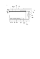
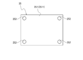
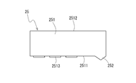
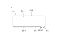
- FIG. 1 is provided from the back, and shows the outline of the example in which the planar-view rectangular support part was formed in each corner of a light-guide part. It is the top view which looked at the light-guide plate with which the liquid crystal display device shown in FIG. 1 is provided from the back surface, and shows the outline of the example by which the planar-view circular support part was formed in each corner of a light guide part. It is the side view which looked at the light-guide plate with which the liquid crystal display device shown in FIG. 1 is provided from the side, and shows the outline of the example in which the side view substantially triangular support part was formed. It is the side view which looked at the light-guide plate with which the liquid crystal display device shown in FIG.
- FIG. 1 is an exploded perspective view of a liquid crystal display device 1 according to an embodiment of the present invention (note that the shape of the support portion 252 shown in FIG. 1 is an example).
- FIG. 2 is an enlarged sectional view of the liquid crystal display device 1 (hatching is omitted for the sake of clarity).
- the front side and the upper side in the following description refer to the upper side in FIGS. 1 and 2, and the back side and the lower side refer to the lower side in FIGS. 1 and 2.
- the liquid crystal display device 1 includes a liquid crystal display panel 10 and a lighting device 20.
- a liquid crystal display panel 10 includes a thin film transistor (TFT) array substrate 12 (hereinafter simply referred to as an array substrate 12) and a color filter (CF) substrate 14, and includes a bezel 11 having a frame shape. It is fixed.
- the array substrate 12 and the color filter substrate 14 face each other with a predetermined cell gap, and a liquid crystal is filled between the substrates.
- the array substrate 12 is obtained by forming TFTs and pixel electrodes in a matrix on a glass substrate. Around these TFTs and pixel electrodes, gate signal lines and source signal lines are formed in a lattice pattern. Among these, the pixel electrode is electrically connected to the drain electrode of the TFT, the source signal line is electrically connected to the source electrode of the TFT, and the gate signal line is electrically connected to the gate electrode of the TFT.
- the liquid crystal display panel 10 is usually provided with a substrate (source substrate or the like) for driving the panel or a driver IC (source driver or the like), but is omitted in FIG.
- the color filter substrate 14 is formed by forming a plurality of color filters in a matrix on a glass substrate having the same size as the array substrate 12 and forming a transparent common electrode on almost the entire surface of the substrate.
- the orientation of the liquid crystal filled between the two substrates is controlled by changing the voltage applied between the pixel electrode and the common electrode.
- the illuminating device 20 (illuminating device according to one embodiment of the present invention) is a backlight device arranged on the back surface of the liquid crystal display panel 10.
- the illuminating device 20 in this embodiment is an LED backlight using an LED light source 28 as a light source.
- the LED light source 28 is arranged along two opposing side surfaces of the liquid crystal display panel 10 (along two opposing side surfaces of the backlight chassis 22). That is, the lighting device 20 is a so-called “edge light type” backlight.
- the lighting device 20 includes a frame 21, a backlight chassis 22 (corresponding to a housing member in the present invention), a reflective sheet 24, and a light guide plate 25 (one embodiment of the present invention).
- a light guide plate one embodiment of the present invention.
- optical members 261, 262, 263, and an LED light source 28 are included in the lighting device 20.
- the frame 21 is a substantially rectangular frame. A cross section of each side constituting the frame is formed in a substantially L shape.
- the frame 21 is for holding the reflection sheet 24, the light guide plate 25, and the optical members 261, 262, and 263 laminated on the backlight chassis 22 inside the backlight chassis 22. That is, as shown in FIG. 2, the reflection sheet 24, the light guide plate 25, and the optical members 261, 262, and 263 are arranged in a space formed by the frame 21 and the backlight chassis 22.
- the backlight chassis 22 is a substantially rectangular member in plan view having a shallow box shape made of, for example, aluminum or an aluminum alloy.
- An LED light source 28 mounted on an LED substrate 281 is disposed on the inner surface of the backlight chassis 22. That is, the LED light source 28 emits light from the side of the backlight chassis 22 toward the center.
- a reflection sheet 24 is laid on the inner bottom surface of the chassis body 22, and a light guide plate 25 is placed on the reflection sheet 24.
- Optical members 261, 262, and 263 are placed on the light guide plate 25.
- the reflection sheet 24 (corresponding to the optical sheet in the present invention) efficiently reflects the light emitted from the side of the backlight chassis 22 by the LED light source 28 toward the liquid crystal display panel 10 side.
- the light guide plate 25 includes a light guide unit 251 that guides light emitted from the LED light source 28, and a support unit 252 that protrudes from the light guide unit 251 (a diffuse reflection surface 2511 described later) to the back side.
- the light guide unit 251 spreads the light reflected by the reflection sheet 24 in a planar shape.
- the light guide unit 251 is placed on the reflection sheet 24 (on the inner bottom surface of the backlight chassis 22) via the support unit 252. Details of the configuration of the light guide plate 25 (configuration of the support portion 252) will be described later.
- the reflection sheet 24 and the light guide plate 25 improve the luminance of light reaching the panel surface of light (edge light) emitted from the LED light source 28 disposed along the side surface of the backlight chassis 22 (liquid crystal display panel 10).
- the brightness in the surface direction of the panel is made uniform.
- Optical members 261, 262, and 263 are thin sheet-like resin products having a rectangular shape in plan view.
- the combination can be appropriately selected according to the characteristics required for the liquid crystal display device 1.
- a combination of a diffusion sheet 261, a lens sheet 262, and a polarization reflection film 263 can be exemplified in order from the bottom.
- the diffusion sheet 261 further uniformizes the luminance in the surface direction of the light reaching the liquid crystal display panel 10.
- the lens sheet 262 collects the light transmitted through the diffusion sheet 261 and increases the luminance.
- the polarization reflection film 263 is polarized in a predetermined direction (light polarized in a predetermined direction) so that the light reaching the liquid crystal display panel 10 is not absorbed by the polarizing plate attached to the light receiving surface (lower surface) of the liquid crystal panel 10. , And the other polarized light is reflected.
- the LED light source 28 is disposed on two inner side surfaces of the backlight chassis 22 that face each other. Specifically, a plurality of LED substrates 281 are arranged on the inner surface of the backlight chassis 22, and a plurality of LED light sources 28 are mounted on each LED substrate 281 in a straight line along the longitudinal direction of the LED substrate 281. Has been.
- the arrangement of the LED light sources 28 is not particularly limited, and may be arranged on each of the four inner surfaces of the backlight chassis 22.
- the LED light source 28 is a so-called white LED that emits white light.
- white LED white LED applicable to this embodiment is not limited to a specific thing.
- a white LED formed by sealing an LED chip that emits blue light with a transparent resin mixed with a yellow phosphor can be used.
- the light guide plate 25 includes the light guide part 251 that guides the light emitted from the LED light source 28 and the support part 252 that protrudes from the back surface of the light guide part 251.
- the light guide portion 251 is a plate-like portion having a substantially rectangular shape in a plan view formed of, for example, an acrylic resin.
- the LED light source 28 is disposed so as to face the side surface of the light guide unit 251.
- a diffuse reflection surface 2511 is formed on the back surface (lower surface) of the light guide unit 251 to diffuse and diffuse the light incident on the light guide unit 251.
- the diffuse reflection surface 2511 is formed with a reflection pattern 2513 for efficiently reflecting light toward the front side.
- the reflective pattern 2513 is formed by printing white ink containing titanium dioxide or the like by an inkjet method.
- the shape and configuration of the reflection pattern 2513 are not particularly limited.
- a known reflection pattern 2513 formed in a planar manner on the light guide 251 can be appropriately applied.
- the reflective pattern 2513 is drawn with an emphasis on the thickness in the cross-sectional views and side views (FIGS. 2 and 7 to 10) of the present application for easy understanding of the drawings. Further, the reflection pattern 2513 is omitted in the plan views (FIGS. 3 to 6) of the present application.
- the opposite surface (front surface) of the diffuse reflection surface 2511 in the light guide unit 251 is a light emission surface 2512 from which the light uniformized in the planar direction by the reflection pattern 2513 is emitted.
- the light emitted from the light emitting surface 2512 is irradiated from the back side (array substrate 12 side) of the liquid crystal display panel 10.
- the support portion 252 is formed so as to protrude from the diffuse reflection surface 2511 of the light guide portion 251 (project toward the back side). By the support portion 252, the light guide portion 251 is supported at a distance from the bottom surface (reflective sheet 24) of the backlight chassis 22.
- the protrusion height (protrusion length) of the support portion 252 is set such that a sufficient interval is maintained such that the diffuse reflection surface 2511 of the light guide portion 251 does not contact the reflection sheet 24.
- the planar shape of the support portion 252 (the shape seen from the back side of the light guide plate 25) is along the opposing side edges (two sides) of the light guide portion 251 having a substantially rectangular shape in plan view, as shown in FIG. Is formed.
- the support portion 252 is formed along the short side of the light guide portion 251, but may be formed along the long side. Moreover, as shown in FIG. 4, you may form along all the side edges (four sides) of the light guide part 251.
- the light guide plate 25 is provided with the support portion 252 that protrudes from the diffuse reflection surface 2511 and supports the light guide portion 251 at a distance from the bottom surface (reflection sheet 24) of the backlight chassis 22. ing. Therefore, the diffuse reflection surface 2511 does not rub against the reflection sheet 24, and damage to the reflection pattern 2513 formed on the diffuse reflection surface 2511 can be prevented.
- the support part 252 of the light guide plate 25 is formed along at least a part of the periphery of the light guide part 251, the support part 252 that supports the light guide part 251 is guided. It also serves as a reinforcing member that prevents the deformation of the light portion 251 and makes it difficult for the light guide portion 251 to be bent by heat. That is, the configuration is suitable when used in a high temperature environment.
- the support portion 252 is preferably formed as much as possible inside.
- the more the support portion 252 that is a reinforcing body is formed on the inner side the more the deflection of the light guide portion 251 near the center can be suppressed, and the deflection of the entire light guide portion 251 can be reduced. is there.
- the position close to the reflection pattern 2513 on the diffuse reflection surface 2511 of the light guide unit 251 is most preferable.
- FIG. 5 is a plan view of the light guide plate 25 according to this modification as seen from the back side.
- the support portions 252 of the light guide plate 25 are formed at the four corners of the light guide portion 251 formed in a substantially rectangular shape in plan view.
- the shapes of the support portions 252 formed at the four corners of the light guide portion 251 are substantially rectangular in plan view.
- the support part 252 in each corner of the light guide part 251, since the light guide part 251 can be supported at intervals with the bottom face (reflective sheet 24) of the backlight chassis 22, The diffuse reflection surface 2511 does not rub against the reflection sheet 24, and damage to the reflection pattern 2513 formed on the diffuse reflection surface 2511 is prevented.
- the support portions 252 are arranged at the respective corners as described above, the size of the support portions 252 can be reduced, so that the manufacturing cost of the light guide plate 25 can be suppressed.
- each support portion 252 formed at the four corners of the light guide portion 251 may be a substantially rectangular shape in plan view as shown in FIG. 5, or a substantially circular shape in plan view as shown in FIG. It may be.
- the support portion 252 is formed in a substantially triangular shape when viewed from the side. That is, the tip of the support portion 252 is tapered.
- the support part 252 and the reflective sheet 24 will be in the state of a point contact or a line contact. For example, as shown in FIGS.
- the contact portion 252 is in line contact (provided with a protrusion that is locally point contact). However, if it is the support part 252 formed in each corner of the light guide part 251, as shown in FIG.5 and FIG.6, it will be a point contact.
- the configuration is suitable when used in a high temperature environment.
- the shape viewed from the side of the support portion 252 is a substantially arc shape (dome shape when viewed three-dimensionally). With such a shape, breakage and deformation of the tapered support portion 252 are prevented.
- it can also be set as the structure which formed the level
- FIG. 2 it is possible to adopt a configuration in which the tip of the support portion 252 is formed in a flat shape and the light guide portion 251 is supported in a state where the flat tip is in contact with the reflection sheet 24. .
- the support portion 252 and the reflection sheet 24 are in surface contact, and the reflection sheet 24 is pressed against the bottom surface of the backlight chassis 22 by the light guide plate 25.
- the reflected sheet 24 thus made difficult to move.
- a modification of the support portion 252 having a flat tip a configuration having a substantially trapezoidal shape in a side view as shown in FIG. 10 can be exemplified.
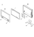
- FIG. 11 is an exploded perspective view showing a schematic configuration of the television receiver 2 according to the embodiment of the present invention.
- the television receiver 2 includes the liquid crystal display device 1, a tuner 41, a power source 42, a loudspeaker 43, cabinets 441 and 442, and a support member 45. Since the tuner 41, the loudspeaker 43, the power source 42, the cabinets 441 and 442, and the support member 45 can be those commonly used in the related art, they will be briefly described, and detailed description thereof will be omitted.
- the tuner 41 generates an image signal and an audio signal of a predetermined channel from the received radio wave.
- the tuner 41 may be a conventional general terrestrial tuner (analog terrestrial tuner, digital terrestrial tuner, or both) BS tuner, CS tuner, or the like.
- the loudspeaker 43 emits sound based on the sound signal generated by the tuner 41. As this loudspeaker 43, a general speaker or the like can be applied.
- the power source 42 can supply power to the liquid crystal display device 1, the tuner 41, the loudspeaker 43, and the like according to the embodiment of the present invention.
- FIG. 11 shows a configuration in which the cabinet includes a front side cabinet 441 and a back side cabinet 442, and the display device 1, the tuner 41, the loudspeaker 43, and the power source 42 are housed between these cabinets.
- the tuner 41, the loudspeaker 43, and the power source 42 may be assembled to the liquid crystal display device 1.
- the reflection sheet 24 is disposed so as to face the diffuse reflection surface 2511 of the light guide plate 25, but other optical sheets may be used.
- the present invention is more effective if it is an optical sheet that is easily bent by heat. Further, a configuration in which such an optical sheet is not disposed at all may be used.
Landscapes
- Physics & Mathematics (AREA)
- Engineering & Computer Science (AREA)
- Multimedia (AREA)
- Signal Processing (AREA)
- General Physics & Mathematics (AREA)
- Optics & Photonics (AREA)
- Planar Illumination Modules (AREA)
Abstract
拡散反射面における反射パターンの損傷を防止できる導光板、この種の導光板が用いられた照明装置、この照明装置が用いられた液晶表示装置、および、この液晶表示装置が用いられたテレビジョン受信機を提供する。 導光する光を拡散反射させる反射パターン2513が形成された拡散反射面2511、および、光が出射する光出射面2512が形成された導光部251と、拡散反射面2511より突出した支持部252とを有する導光板25とし、支持部252によってバックライトシャーシ22(反射シート24)と間隔をあけて導光部251を支持する構成とする。
Description
本発明は、輝度分布を均一にするために用いられる導光板、導光板が用いられた照明装置、この照明装置が用いられた液晶表示装置、および、この液晶表示装置が用いられたテレビジョン受信機に関する。
液晶表示装置は、液晶表示パネルに向けて光を照射する照明装置を備える。かかる照明装置としては、光源からの光を均一にして液晶表示パネルに照射するため、導光板を利用したものが知られている。このような照明装置を有する液晶表示装置の断面を図12(ハッチングは省略してある)に示す。
図12に示すいわゆるエッジライト型の照明装置を有する液晶表示装置100は、バックライトシャーシ102(収容部材)の内側面に配された光源104を有する。その光源104から出射された光は、導光板106の側面から導光板106内に入り込み、導光板106の光出射面1061から液晶表示パネル108に向けて出射される。なお、導光板106とバックライトシャーシ102の底面との間には、光源104からの光を有効利用するための反射シート110が配されるのが一般的である。
導光板106から液晶表示パネル108に出射される光の輝度分布を均一にするため、導光板106における光出射面1061の反対側の面には、光を乱反射させて光を拡散させる拡散反射面1062形成される。拡散反射面1062は、例えば、二酸化チタンなどを含む白色のインクが所定のパターン1063(以下、かかるパターンを反射パターン1063と称する)に印刷されることによって形成される(例えば、特許文献1参照)。
図12に示される従来の導光板106は、(反射シート110を介して)バックライトシャーシ102にそのまま載置された構成である。したがって、振動などで導光板106が動くと、拡散反射面1061と反射シート110(反射シート110が配されていない場合にはバックライトシャーシ102)とが擦れ合い、拡散反射面1061に形成された反射パターン1063が削られてしまうという問題があった。かかる問題は、液晶表示パネル108によって表示される画像の輝度ムラによる表示品質の低下を招く。
本発明が解決しようとする課題は、拡散反射面における反射パターンの損傷を防止できる導光板、この種の導光板が用いられた照明装置、この照明装置が用いられた液晶表示装置、および、この液晶表示装置が用いられたテレビジョン受信機を提供することにある。
上記課題を解決するために本発明にかかる導光板は、導光する光を拡散反射させる反射パターンが形成された拡散反射面、および、光が出射する光出射面が形成された導光部と、前記拡散反射面より突出した支持部と、を有すること要旨とする。
この場合、前記支持部は、前記導光部の周縁の少なくとも一部に沿って形成されていればよく、前記導光部が平面視略矩形状に形成されている場合には、前記支持部は、少なくとも前記導光部の対向する側縁に沿って形成されていればよい。
またあるいは、前記支持部は、前記導光部の各隅に形成されていてもよく、前記導光部が、平面視略矩形状に形成されいる場合には、前記支持部は、前記導光部の四隅に形成されていればよい。
一方、本発明にかかる照明装置は、光源と、この光源から出射された光を導光する導光板と、これら光源および導光板が収容された収容部材を備え、前記導光板は、導光する光を拡散反射させる反射パターンが形成された拡散反射面、および、光が出射する光出射面が形成された導光部と、前記拡散反射面より突出し、前記収容部材と間隔をあけて前記導光部を支持する支持部と、を有することを要旨とする。
この場合、前記拡散反射面と対向して前記収容部材内に配された光学シートをさらに備え、前記支持部は、先細に形成された先端が前記光学シートに接触した状態で前記導光部を支持していればよい。
そして、この場合には、前記支持部の側方から見た形状が略三角形状、略円弧形状であればよい。また、前記支持部の外周に段差が形成された形状であってもよい。
一方、前記導光部の拡散反射面と対向して前記収容部材内に配された光学シートをさらに備え、前記支持部は、平面状に形成された先端が前記光学シートに接触した状態で前記導光部を支持していてもよい。
またこの場合、前記支持部は、前記導光部の周縁の少なくとも一部に沿って形成されていればよく、前記導光部が平面視略矩形状に形成されている場合には、前記支持部は、少なくとも前記導光部の対向する側縁に沿って形成されていればよい。
またあるいは、前記支持部は、前記導光部の各隅に形成されていてもよく、前記導光部が、平面視略矩形状に形成されいる場合には、前記支持部は、前記導光部の四隅に形成されていればよい。
そして、本発明にかかる液晶表示装置は、上記いずれかの照明装置を有することを要旨とする。
また、本発明にかかるテレビジョン受信機は、上記液晶表示装置を有することを要旨とする。
本発明にかかる導光板、照明装置、液晶表示装置、および、テレビジョン受信機は、拡散反射面から突出した支持部を有するため、拡散反射面が他の部材(反射シートなど)と擦れ合うことがない。したがって、拡散反射面に形成された反射パターンの損傷を防止することができる。したがって、液晶表示装置や、テレビジョン受信機では、輝度ムラのない表示品質に優れた画像を提供できる。
上記支持部が導光部の周縁の少なくとも一部に沿って形成されていれば、また、導光部が平面視略矩形状に形成されており、少なくとも導光部の対向する側縁に沿って支持部が形成されていれば、支持部によって導光部が補強され、熱によって導光部が撓みにくくなる。すなわち、高温環境下で使用される場合に適した構成となる。
上記支持部が導光部の各隅に形成されていれば、また、導光部が平面視略矩形状に形成されており、その導光部の四隅に支持部が形成されていれば、支持部の大きさを小さくできるため、導光板の製造コストを抑えることができる。
照明装置、液晶表示装置、あるいは、テレビジョン受信機において、拡散反射面と対向して収容部材内に光学シート(例えば、反射シート)が配されている場合に、先細に形成された支持部の先端が光学シートに接触した状態で導光部を支持していれば、熱によって光学シートが撓むことを抑制することができる。すなわち、支持部と光学シートが(略)点接触または線接触の状態となる(導光板によって光学シートの多くの部分が押さえつけられた状態にならない)から、高温環境下で反射シートが平面的に膨張することができ、反射シートに撓みが生じにくい。したがって、高温環境下で使用される場合に適した構成となる。
この場合、支持部の側方から見た形状を略三角形状とすれば、支持部を先細にする加工が容易である。また、支持部の側方から支持部の側方から見た形状を略円弧形状とすれば、先細に形成した支持部の破損、変形が防止される。また、支持部の外周に段差を形成し、収容部材内に配される他の部材を収容可能なスペースを設ければ、装置の小型化につながる。
照明装置、液晶表示装置、あるいは、テレビジョン受信機において、拡散反射面と対向して収容部材内に光学シート(例えば、反射シート)が配されている場合に、平面状に形成された支持部の先端が光学シートに接触した状態で導光部を支持していれば、支持部と光学シートが面接触となり、光学シートが導光板によって押さえつけられた状態となるから、収容部材内に配された光学シートが動きにくい。
以下、本発明の一実施形態にかかる液晶表示装置1(本発明の一実施形態にかかる導光板25および照明装置20を含む)について、図面を参照して詳細に説明する。図1は、本発明の一実施形態にかかる液晶表示装置1の分解斜視図である(なお、図1に示す支持部252の形状は一例である)。図2は、液晶表示装置1の拡大断面図(図を分かりやすくするため、ハッチングは省略してある)である。なお、特に明示した場合を除き、以下の説明における前面側、上側とは図1および図2における上側をいい、背面側、下側とは図1および図2における下側をいう。
本実施形態にかかる液晶表示装置1は、液晶表示パネル10および照明装置20を備える。図1に示すように、液晶表示パネル10は、薄膜トランジスタ(TFT)アレイ基板12(以下、単にアレイ基板12と称する)と、カラーフィルタ(CF)基板14とを備え、額縁形状を有するベゼル11によって固定されている。アレイ基板12とカラーフィルタ基板14は、所定のセルギャップをおいて対向し、その基板間に液晶が充填されている。
アレイ基板12は、ガラス基板上に、TFTおよび画素電極などがマトリクス状に形成されたものである。これらTFTおよび画素電極の周りにはゲート信号線およびソース信号線が格子状をなして形成されている。これらのうち、画素電極はTFTのドレイン電極に、ソース信号線はTFTのソース電極に、ゲート信号線はTFTのゲート電極にそれぞれ電気的に接続されている。なお、液晶表示パネル10には、通常、パネルを駆動するための基板(ソース基板など)やドライバIC(ソースドライバなど)が取り付けられているが、図1では省略してある。
カラーフィルタ基板14は、アレイ基板12とほぼ同じ大きさのガラス基板上に、複数のカラーフィルタがマトリクス状に形成されるとともに、基板のほぼ全面に透明の共通電極が形成されたものである。両基板の間に充填された液晶は、画素電極および共通電極との間に印可する電圧を変化させることによって配向制御される。
照明装置20(本発明の一実施形態にかかる照明装置)は、液晶表示パネル10の背面に配されたバックライト装置である。本実施形態における照明装置20は、光源としてLED光源28を用いたLEDバックライトである。LED光源28は、液晶表示パネル10の対向する二側面に沿うように(バックライトシャーシ22の対向する二側面に沿うように)配されている。つまり、照明装置20は、いわゆる「エッジライト型」バックライトである。
図1および図2に示すように、照明装置20は、フレーム21と、バックライトシャーシ22(本発明における収容部材に相当する)と、反射シート24と、導光板25(本発明の一実施形態にかかる導光板)と、光学部材261、262、263と、LED光源28とを備える。
フレーム21は、略矩形の枠体である。枠を構成する各辺の断面は略L字状に形成されている。このフレーム21は、バックライトシャーシ22上に積層された反射シート24、導光板25、および、光学部材261、262、263を、バックライトシャーシ22内部に保持させるためのものである。すなわち、図2に示すように、反射シート24、導光板25、および、光学部材261、262、263は、フレーム21およびバックライトシャーシ22によって形成される空間内に配されている。
バックライトシャーシ22は、例えばアルミニウムまたはアルミニウム合金から形成された浅い箱形状を有する平面視略方形状の部材である。バックライトシャーシ22の内側面には、LED基板281に実装されたLED光源28が配されている。つまり、LED光源28からは、バックライトシャーシ22の側方から中央に向けて光が出射される。シャーシ体22の内底面には、反射シート24が敷かれ、その反射シート24の上に導光板25が載置されている。導光板25の上には、光学部材261、262、263が載置されている。
反射シート24(本発明における光学シートに相当する)は、LED光源28によってバックライトシャーシ22の側方から出射された光を、液晶表示パネル10側に向けて効率よく反射させる。
導光板25は、LED光源28から出射された光を導光する導光部251、および、この導光部251(後述する拡散反射面2511)から背面側に突出した支持部252とを備える。導光部251は、反射シート24によって反射された光を平面状に拡げる。この導光部251が、支持部252を介して反射シート24の上(バックライトシャーシ22の内底面上)に載置されている。かかる導光板25の構成(支持部252の構成)の詳細については後述する。
これら反射シート24および導光板25により、バックライトシャーシ22(液晶表示パネル10)の側面に沿って配されるLED光源28から出射される光(エッジライト)のパネル表面に到達する光の輝度向上、パネルの面方向における輝度の均一化が図られている。
光学部材261、262、263は、平面視矩形の薄いシート状の樹脂製品である。その組合せとしては液晶表示装置1に求められる特性などに応じて適宜選択可能である。例えば、下から順に拡散シート261、レンズシート262、偏光反射フィルム263といった組合せが例示できる。拡散シート261は、液晶表示パネル10に到達する光の面方向における輝度をさらに均一化させるものである。レンズシート262は、拡散シート261を透過した光を集光し、輝度を高めるものである。偏光反射フィルム263は、液晶表示パネル10に到達した光が、液晶パネル10の受光面(下面)に貼付された偏光板に吸収されないよう、所定の方向の偏光(所定の方向に偏光する光)を透過し、それ以外の偏光を反射するものである。
LED光源28は、バックライトシャーシ22の対向する二つの内側面に配されている。具体的には、バックライトシャーシ22の内側面に複数のLED基板281が配されており、各LED基板281上に複数のLED光源28が、LED基板281の長手方向に沿って直線状に実装されている。なお、かかるLED光源28の配置の構成は特に限定されるものではなく、バックライトシャーシ22の四つの内側面のそれぞれに配された構成であってもよい。
LED光源28は、白色光を発光させるいわゆる白色LEDである。白色LEDとしては種々のものが知られているが、本実施形態に適用できる白色LEDは特定のものに限定されない。例えば、青色光を発光させるLEDチップを黄色蛍光体が混合された透明樹脂で密封してなる白色LEDを用いることができる。
以下、上記照明装置20が備える導光板25の構成について詳細に説明する。上述したように、導光板25は、LED光源28から出射された光を導光する導光部251と、導光部251の背面から突出した支持部252とを有する。
導光部251は、例えばアクリル樹脂などで成形された平面視略矩形状の板状の部分である。かかる導光部251の側面と対向するように、上記LED光源28が配されている。導光部251の背面(下面)には、導光部251内に入射した光を乱反射させて拡散させる拡散反射面2511が形成されている。拡散反射面2511には、効率よく前面側に向けて光を反射させるための反射パターン2513が形成されている。本実施形態において、反射パターン2513は、二酸化チタンなどを含む白色のインクがインクジェット方式によって印刷されてなる。ただし、かかる反射パターン2513の形状、構成は特に限定されるものではなない。輝度を均一にするため、導光部251に平面的に形成される公知の反射パターン2513が適宜適用できる。なお、反射パターン2513は、本願の断面図、側面図(図2、図7~図10)において、図を分かりやすくするため、厚みを強調して描いている。また、反射パターン2513は、本願の平面図(図3~図6)では省略してある。
導光部251における拡散反射面2511における反対側の面(前面)は、上記反射パターン2513によって平面方向に均一化された光が出射する光出射面2512となっている。かかる光出射面2512から出射された光が、液晶表示パネル10の背面側(アレイ基板12側)から照射される。
支持部252は、導光部251の拡散反射面2511から突出して(背面側に突出して)形成されている。かかる支持部252によって、導光部251はバックライトシャーシ22の底面(反射シート24)と間隔をあけて支持されている。支持部252の突出高さ(突出長さ)は、導光部251の拡散反射面2511が反射シート24に接触することがない十分な間隔が保たれるように設定されている。一方、支持部252の平面形状(導光板25の背面側から見た形状)は、図3に示すように、平面視略矩形状の導光部251の対向する側縁(二辺)に沿って形成されている。なお、図3に示した構成は、支持部252が導光部251の短辺に沿って形成されたものであるが、長辺に沿って形成されていてもよい。また、図4に示すように、導光部251の側縁全て(四辺)に沿って形成されていてもよい。
このように、本実施形態における導光板25には、拡散反射面2511より突出し、バックライトシャーシ22の底面(反射シート24)と間隔をあけて導光部251を支持する支持部252が設けられている。そのため、拡散反射面2511が反射シート24と擦れ合うことがなく、拡散反射面2511に形成された反射パターン2513の損傷を防止することができる。
また、本実施形態のように、導光板25の支持部252が、導光部251の周縁の少なくとも一部に沿って形成されていれば、導光部251を支持する支持部252が、導光部251の変形を防止する補強部材にもなり、熱によって導光部251が撓みにくくなる。すなわち、高温環境下で使用される場合に適した構成となる。
なお、支持部252はできるだけ内側に形成するとよい。補強体である支持部252が内側に形成されればされるほど、導光部251の中央寄り位置の撓みを抑制することができ、導光部251全体の撓みを小さく抑えることができるからである。具体的には、導光部251の拡散反射面2511における反射パターン2513に近接する位置が最も好適である。
次に、導光板25の支持部252の平面形状(導光板25の背面側から見た形状)の変形例について説明する。図5は、この変形例にかかる導光板25を背面側から見た平面図である。図示されるように、この導光板25の支持部252は、平面視略矩形状に形成された導光部251の四隅に形成されている。この導光部251の四隅に形成された各支持部252の形状は、平面視略矩形状である。
このように、導光部251の各隅に支持部252を配した構成としても、バックライトシャーシ22の底面(反射シート24)と間隔をあけて導光部251を支持することができるから、拡散反射面2511が反射シート24と擦れ合うことがなく、拡散反射面2511に形成された反射パターン2513の損傷が防止される。また、このように各隅に支持部252を配した構成であれば、支持部252全体の大きさを小さくできるため、導光板25の製造コストを抑えることができる。
また、導光部251の四隅に形成された各支持部252の形状は、図5に示したように平面視略矩形状であってもよいし、図6に示すように、平面視略円形であってもよい。
次に、導光部251を導光板25の側面から見た形状(導光部251の断面形状)について説明する。図7に示した構成は、支持部252が側方視略三角形状に形成されたものである。つまり、支持部252の先端が先細になっている。このように支持部252の先端が先細に形成されていれば、支持部252と反射シート24とは、点接触あるいは線接触の状態となる。例えば、図3や図4に示したような、導光部251の周縁に沿って形成された支持部252であれば線接触となり(ただし、局所的に点接触となるような突起を設けることもできる)、図5や図6に示したような、導光部251の各隅に形成された支持部252であれば点接触となる。
このように、支持部252の先端が先細に形成され、支持部252と反射シート24が点接触あるいは線接触の状態であれば、導光板25によって反射シート24の多くの部分が押さえつけられた状態にない(支持部252と反射シート24の接触面積が小さい)から、高温環境下で反射シート24が平面的に膨張することができ、反射シート24に撓みが生じにくい。したがって、高温環境下で使用される場合に適した構成となる。
このように支持部252の先端を先細にし、支持部252と反射シート24を点接触あるいは線接触の状態とした構成の変形例として、次のような構成が考えられる。図8に示す構成は、支持部252の側方から見た形状を略円弧形状(三次元的に見ればドーム形状)としたものである。かかる形状とすれば、先細に形成した支持部252の破損、変形が防止される。また、図9に示すように、支持部252の外周に段差252aを形成した構成とすることもできる。かかる構成とすれば、当該段差252aによって他の部材を収容可能なスペースが生まれるため、装置の小型化につながる。また、支持部252の根本側の十分な強度を維持しつつ、先細の形状とすることができる。
一方、図2に示したように、支持部252の先端を平面状に形成し、その平面状の先端が反射シート24に接触した状態で導光部251を支持する構成を採用することもできる。このような構成とすれば、支持部252と反射シート24が面接触となり、反射シート24が導光板25によってバックライトシャーシ22の底面に押さえつけられた状態となるから、バックライトシャーシ22内に配された反射シート24が動きにくい。この支持部252の先端を平面形状にしたものの変形例としては、図10に示したような、側面視略台形状である構成が例示できる。
次に、本発明の実施形態にかかるテレビジョン受信機について説明する。図11は、本発明の実施形態にかかるテレビジョン受信機2の概略構成を示した分解斜視図である。
図11に示すように、このテレビジョン受信機2は、上記液晶表示装置1と、チューナ41と、電源42と、拡声手段43と、キャビネット441、442と、支持部材45とを備える。チューナ41、拡声手段43、電源42、キャビネット441、442、および、支持部材45は、従来一般に用いられるものが適用できるから、それぞれ簡単に説明し、詳細な説明は省略する。
チューナ41は、受信した電波から所定のチャンネルの画像信号と音声信号とを生成する。このチューナ41には、従来一般の地上波チューナ(アナログ地上波用のチューナ、デジタル地上波用のチューナ、またはこれら双方)BSチューナ、CSチューナなどが適用できる。拡声手段43は、チューナ41が生成した音声信号に基づいて音声を発する。この拡声手段43には、一般的なスピーカなどが適用できる。電源42は、本発明の実施形態にかかる液晶表示装置1、チューナ41、拡声手段43などに対して電力を供給することができる。
そして、液晶表示装置1、チューナ41、拡声手段43、電源42が、キャビネット441、442に収納され、支持部材45により支持される。図11は、キャビネットが前面側キャビネット441と背面側キャビネット442からなり、これらの間に表示装置1、チューナ41、拡声手段43、電源42が収納される構成を示す。このほか、チューナ41、拡声手段43、電源42が、液晶表示装置1に組み付けられる構成であってもよい。
以上、本発明の実施の形態について詳細に説明したが、本発明は上記実施の形態に何ら限定されるものではなく、本発明の要旨を逸脱しない範囲で種々の改変が可能である。
例えば、上記実施形態では、導光板25の拡散反射面2511に対向して、反射シート24が配されていることを説明したが、その他の光学シートであってもよい。熱によって撓みやすいような光学シートであれば、本発明はより有効である。また、このような光学シートが全く配されていない構成であってもよい。
Claims (17)
- 導光する光を拡散反射させる反射パターンが形成された拡散反射面、および、光が出射する光出射面が形成された導光部と、
前記拡散反射面より突出した支持部と、を有することを特徴とする導光板。 - 前記支持部は、前記導光部の周縁の少なくとも一部に沿って形成されていることを特徴とする請求項1に記載の導光板。
- 前記導光部は、平面視略矩形状に形成され、
前記支持部は、少なくとも前記導光部の対向する側縁に沿って形成されていることを特徴とする請求項2に記載の導光板。 - 前記支持部は、前記導光部の各隅に形成されていることを特徴とする請求項1に記載の導光板。
- 前記導光部は、平面視略矩形状に形成され、
前記支持部は、前記導光部の四隅に形成されていることを特徴とする請求項4に記載の導光板。 - 光源と、この光源から出射された光を導光する導光板と、これら光源および導光板が収容された収容部材を備えた照明装置であって、
前記導光板は、
導光する光を拡散反射させる反射パターンが形成された拡散反射面、および、光が出射する光出射面が形成された導光部と、
前記拡散反射面より突出し、前記収容部材と間隔をあけて前記導光部を支持する支持部と、を有することを特徴とする照明装置。 - 前記拡散反射面と対向して前記収容部材内に配された光学シートをさらに備え、
前記支持部は、先細に形成された先端が前記光学シートに接触した状態で前記導光部を支持していることを特徴とする請求項6に記載の照明装置。 - 前記支持部の側方から見た形状が略三角形状であることを特徴とする請求項7に記載の照明装置。
- 前記支持部の側方から見た形状が略円弧形状であることを特徴とする請求項7に記載の照明装置。
- 前記支持部の外周に段差が形成されていることを特徴とする請求項7に記載の照明装置。
- 前記導光部の拡散反射面と対向して前記収容部材内に配された光学シートをさらに備え、
前記支持部は、平面状に形成された先端が前記光学シートに接触した状態で前記導光部を支持していることを特徴とする請求項6に記載の照明装置。 - 前記支持部は、前記導光部の周縁の少なくとも一部に沿って形成されていることを特徴とする請求項6から請求項11のいずれか一項に記載の照明装置。
- 前記導光部は、平面視略矩形状に形成され、
前記支持部は、少なくとも前記導光部の対向する側縁に沿って形成されていることを特徴とする請求項12に記載の照明装置。 - 前記支持部は、前記導光部の各隅に形成されていることを特徴とする請求項6から請求項11のいずれか一項に記載の照明装置。
- 前記導光部は、平面視略矩形状に形成され、
前記支持部は、前記導光部の四隅に形成されていることを特徴とする請求項14に記載の照明装置。 - 請求項6から請求項15のいずれか一項に記載の照明装置を有する液晶表示装置。
- 請求項16に記載の液晶表示装置を有するテレビジョン受信機。
Applications Claiming Priority (2)
| Application Number | Priority Date | Filing Date | Title |
|---|---|---|---|
| JP2010-206336 | 2010-09-15 | ||
| JP2010206336 | 2010-09-15 |
Publications (1)
| Publication Number | Publication Date |
|---|---|
| WO2012035896A1 true WO2012035896A1 (ja) | 2012-03-22 |
Family
ID=45831370
Family Applications (1)
| Application Number | Title | Priority Date | Filing Date |
|---|---|---|---|
| PCT/JP2011/067305 Ceased WO2012035896A1 (ja) | 2010-09-15 | 2011-07-28 | 導光板、照明装置、液晶表示装置、および、テレビジョン受信機 |
Country Status (1)
| Country | Link |
|---|---|
| WO (1) | WO2012035896A1 (ja) |
Cited By (1)
| Publication number | Priority date | Publication date | Assignee | Title |
|---|---|---|---|---|
| DE112012006940B4 (de) * | 2012-09-26 | 2021-04-01 | Shenzhen China Star Optoelectronics Technology Co., Ltd. | Hintergrundbeleuchtungsmodul |
Citations (6)
| Publication number | Priority date | Publication date | Assignee | Title |
|---|---|---|---|---|
| JPS5953703U (ja) * | 1982-09-30 | 1984-04-09 | 日本精機株式会社 | 照明装置 |
| JPH06308489A (ja) * | 1993-04-26 | 1994-11-04 | Tosoh Corp | パネル用バックライト |
| JPH0862430A (ja) * | 1994-08-22 | 1996-03-08 | Copal Co Ltd | 面発光装置 |
| JP2005309455A (ja) * | 2005-05-20 | 2005-11-04 | Seiko Epson Corp | 照明用光源基板、液晶装置及び電子機器 |
| WO2007060776A1 (ja) * | 2005-11-28 | 2007-05-31 | Sharp Kabushiki Kaisha | バックライト装置及びこれを用いた液晶表示装置 |
| JP2007157457A (ja) * | 2005-12-02 | 2007-06-21 | Matsushita Electric Works Ltd | 平面発光装置 |
-
2011
- 2011-07-28 WO PCT/JP2011/067305 patent/WO2012035896A1/ja not_active Ceased
Patent Citations (6)
| Publication number | Priority date | Publication date | Assignee | Title |
|---|---|---|---|---|
| JPS5953703U (ja) * | 1982-09-30 | 1984-04-09 | 日本精機株式会社 | 照明装置 |
| JPH06308489A (ja) * | 1993-04-26 | 1994-11-04 | Tosoh Corp | パネル用バックライト |
| JPH0862430A (ja) * | 1994-08-22 | 1996-03-08 | Copal Co Ltd | 面発光装置 |
| JP2005309455A (ja) * | 2005-05-20 | 2005-11-04 | Seiko Epson Corp | 照明用光源基板、液晶装置及び電子機器 |
| WO2007060776A1 (ja) * | 2005-11-28 | 2007-05-31 | Sharp Kabushiki Kaisha | バックライト装置及びこれを用いた液晶表示装置 |
| JP2007157457A (ja) * | 2005-12-02 | 2007-06-21 | Matsushita Electric Works Ltd | 平面発光装置 |
Cited By (1)
| Publication number | Priority date | Publication date | Assignee | Title |
|---|---|---|---|---|
| DE112012006940B4 (de) * | 2012-09-26 | 2021-04-01 | Shenzhen China Star Optoelectronics Technology Co., Ltd. | Hintergrundbeleuchtungsmodul |
Similar Documents
| Publication | Publication Date | Title |
|---|---|---|
| JP4485358B2 (ja) | バックライトアセンブリ及び液晶表示装置 | |
| EP2913706B1 (en) | Liquid crystal display device | |
| US10180534B2 (en) | Borderless display device including display module | |
| KR100878206B1 (ko) | 광학 시트, 이를 이용한 백라이트 어셈블리 및 액정표시장치 | |
| US9746602B2 (en) | Backlight device and display device including the same | |
| WO2012039196A1 (ja) | 照明装置、表示装置およびテレビ受信装置 | |
| US8517554B2 (en) | Frame for light source device, light source device, and display device | |
| WO2012023322A1 (ja) | 照明装置、表示装置およびテレビ受信装置 | |
| US20120327686A1 (en) | Light source module and display device having the same | |
| WO2011013406A1 (ja) | エッジライト式照明装置、液晶表示装置及びテレビ受信装置 | |
| JP2010002486A (ja) | 液晶表示装置 | |
| JP2014123106A (ja) | 液晶表示装置 | |
| US8491169B2 (en) | Frame, light source device, display device, and television receiver | |
| KR20150084216A (ko) | 광학패턴시트, 이를 포함하는 백라이트 유닛 및 표시장치 | |
| WO2012081395A1 (ja) | 照明装置およびこれを備えた液晶表示装置 | |
| WO2013039001A1 (ja) | 照明装置、表示装置、及びテレビ受信装置 | |
| WO2013129244A1 (ja) | 表示装置、及びテレビ受信装置 | |
| KR20090046405A (ko) | 액정표시장치용 백라이트 유닛 및 액정표시장치모듈 | |
| US20100073915A1 (en) | Lamp case, and backlight device and flat display device using it | |
| KR101292585B1 (ko) | 액정표시장치 | |
| KR20090128693A (ko) | 액정표시장치 | |
| WO2012017721A1 (ja) | 照明装置、液晶表示装置及びテレビ受信装置 | |
| KR20150063783A (ko) | 액정 표시 장치 및 그 조립 방법 | |
| WO2012035896A1 (ja) | 導光板、照明装置、液晶表示装置、および、テレビジョン受信機 | |
| KR20100072652A (ko) | 액정표시장치 |
Legal Events
| Date | Code | Title | Description |
|---|---|---|---|
| 121 | Ep: the epo has been informed by wipo that ep was designated in this application |
Ref document number: 11824904 Country of ref document: EP Kind code of ref document: A1 |
|
| NENP | Non-entry into the national phase |
Ref country code: DE |
|
| 122 | Ep: pct application non-entry in european phase |
Ref document number: 11824904 Country of ref document: EP Kind code of ref document: A1 |
|
| NENP | Non-entry into the national phase |
Ref country code: JP |