WO2012035595A1 - 再生装置、再生方法及び再生プログラム - Google Patents
再生装置、再生方法及び再生プログラム Download PDFInfo
- Publication number
- WO2012035595A1 WO2012035595A1 PCT/JP2010/065719 JP2010065719W WO2012035595A1 WO 2012035595 A1 WO2012035595 A1 WO 2012035595A1 JP 2010065719 W JP2010065719 W JP 2010065719W WO 2012035595 A1 WO2012035595 A1 WO 2012035595A1
- Authority
- WO
- WIPO (PCT)
- Prior art keywords
- waveform
- phase
- playback
- cut
- randomizing
- Prior art date
- Legal status (The legal status is an assumption and is not a legal conclusion. Google has not performed a legal analysis and makes no representation as to the accuracy of the status listed.)
- Ceased
Links
Images




Classifications
-
- G—PHYSICS
- G10—MUSICAL INSTRUMENTS; ACOUSTICS
- G10L—SPEECH ANALYSIS TECHNIQUES OR SPEECH SYNTHESIS; SPEECH RECOGNITION; SPEECH OR VOICE PROCESSING TECHNIQUES; SPEECH OR AUDIO CODING OR DECODING
- G10L21/00—Speech or voice signal processing techniques to produce another audible or non-audible signal, e.g. visual or tactile, in order to modify its quality or its intelligibility
- G10L21/04—Time compression or expansion
- G10L21/043—Time compression or expansion by changing speed
- G10L21/045—Time compression or expansion by changing speed using thinning out or insertion of a waveform
- G10L21/049—Time compression or expansion by changing speed using thinning out or insertion of a waveform characterised by the interconnection of waveforms
Definitions
- the present invention relates to a technical field for performing tempo conversion on an audio signal or the like.
- a technique for compressing or expanding a time axis of a digital signal such as an audio signal is known. That is, a technique for changing the reproduction speed when reproducing an audio signal or the like (hereinafter referred to as “tempo conversion” or “time stretch”) has been proposed. In addition, a technique has been proposed in which tempo conversion is performed without changing the pitch of a digital signal. This is equivalent to changing the reproduction speed of the music while maintaining the pitch.
- tempo conversion is performed by combining both ends of a waveform cut out from an original digital signal while crossfading, and a cutout start position of a cutout waveform is set from a search start position to a search end position. It has been proposed to determine the cross-fade waveforms between the most similar positions. Further, in Patent Document 2, even if the tempo of the audio information is changed, the pitch is changed so that the pitch of the audio information is the same as the pitch of the audio information recorded on the storage medium, or the audio information is changed. It has been proposed not to change the pitch.
- JP 2000-322100 A Japanese Patent No. 3402490
- the invention described in claim 1 is a playback device that performs playback by performing tempo conversion on an input signal.
- the playback apparatus includes: a waveform cutout unit that cuts out a waveform from the input signal; and a process of randomizing a phase according to a playback speed at which the tempo conversion is performed on the waveform cut out by the waveform cutout unit. Performing phase randomization means.
- the invention according to claim 10 is a reproduction method for reproducing an input signal by performing tempo conversion.
- the reproduction method includes a waveform cutout step of cutting out a waveform from the input signal, and a process of randomizing a phase according to the playback speed at which the tempo conversion is performed on the waveform cut out in the waveform cutout step. Performing a phase randomization step.
- the invention according to claim 11 is a reproduction program that is executed by a computer and performs reproduction by performing tempo conversion on an input signal.
- the reproduction program randomizes the phase of the computer in accordance with the reproduction speed at which the tempo conversion is performed on the waveform cut out by the waveform cutout unit that cuts out the waveform from the input signal. Function as phase randomizing means for performing the processing.
- the figure for demonstrating the method of a general tempo conversion is shown. It is a block diagram which shows schematic structure of the reproducing
- a playback apparatus that performs tempo conversion on an input signal and reproduces the waveform cuts out a waveform from the input signal, and a waveform cut out by the waveform cut-out means
- phase randomizing means for performing a process of randomizing the phase according to the reproduction speed for performing the tempo conversion is provided.
- the above-described playback device is preferably used for playing back an input signal by performing tempo conversion, that is, playing back an audio signal or the like by changing the playback speed.
- the waveform cutout means cuts out a waveform from the input signal. Specifically, the waveform cutout unit repeatedly cuts out a waveform having a predetermined length in the time axis direction from a waveform corresponding to a continuous input signal at a predetermined cycle.
- waveform does not mean the shape of a signal or the like, but means data of a signal that is temporally continuous.
- the phase randomizing means performs a process for randomizing the phase in accordance with the reproduction speed at which the tempo conversion is performed on the waveform thus cut out. Specifically, the phase randomizing means randomizes the phase of each frequency in the frequency domain of the clipped waveform according to the reproduction speed. Thereby, it is possible to appropriately suppress the occurrence of sound quality deterioration due to tempo conversion. For example, it is possible to appropriately suppress the generation of a sound (beat sound) according to the loop period.
- the phase randomizing unit performs a process of multiplying the extracted waveform by a vector whose length is “1” and whose phase is random according to the reproduction speed.
- the phase randomizing means performs phase randomization by multiplying each frequency element in the extracted waveform by a vector having a length of “1” and a phase that is random according to the reproduction speed. This makes it possible to realize a smoother and wider tempo conversion.
- the phase randomizing unit performs the randomizing process only when the reproduction speed is less than “1”.
- the process of randomizing the phase is not performed. In this way, the processing load can be reduced by selectively randomizing according to the reproduction speed.
- a process of circulating the currently cut waveform according to a phase shift between the waveform previously cut by the waveform cutting means and the waveform cut this time by the waveform cutting means And a phase randomizing unit that performs the randomizing process on the waveform that has been subjected to the cyclic processing by the waveform cyclic unit.
- the processing can be simplified by performing the processing on the cut-out waveform and performing the steady processing only by reproducing in accordance with the phase. For example, it is not necessary to perform adaptive processing in consideration of the crossfade position (in other words, the smoothing position), the waveform cut-out position, and the like.
- the waveform circulator performs a process of advancing or delaying the phase of the waveform that has been extracted this time by the amount of the phase shift, and the phase shift amount of the waveform that has been extracted this time.
- the sample corresponding to is turned to the back or front of the waveform cut out this time.
- the phase randomizing means performs the randomizing process on a waveform obtained by Fourier transforming the waveform subjected to the cyclic processing by the waveform circulating means.
- the waveform circulating means performs the process of circulating the waveform obtained by Fourier transforming the extracted waveform.
- the playback apparatus further includes loop waveform forming means for performing processing for converting the clipped waveform into a waveform that can be continuously and repeatedly played back, and the waveform circulation means includes the loop waveform forming means.
- the cyclic processing is performed on the waveform after the conversion processing is performed.
- the loop waveform forming unit corresponds to a waveform obtained by multiplying the cut-out waveform by a triangular window and a section in which the waveform cut-out unit cuts out the waveform.
- a waveform that can be reproduced continuously and repeatedly is obtained by adding a waveform obtained by circulating the obtained waveform on the time axis by a half period.
- the loop waveform forming means circulates the obtained waveform on the time axis by a half of the waveform obtained by multiplying the cut waveform by the triangular window and the length of the cut waveform in the time direction.
- a loop waveform is formed by adding the obtained waveforms.
- a playback method for performing playback by performing tempo conversion on an input signal is cut out by the waveform cutout step of cutting out a waveform from the input signal and the waveform cutout step.
- a reproduction program executed by a computer and performing tempo conversion on an input signal to reproduce the signal is a waveform cutout unit that cuts out a waveform from the input signal.
- the waveform cut out by the waveform cut-out means is made to function as phase randomizing means for performing a process of randomizing the phase in accordance with the reproduction speed for performing the tempo conversion.
- FIG. 1 shows an example of a technique for performing tempo conversion (time stretch) without changing the pitch of a digital signal, which is generally performed.
- a waveform corresponding to a signal to be reproduced is divided into predetermined time intervals (A to G) to represent a reproduction speed (in other words, “reproduction tempo”.
- a to G predetermined time intervals
- reproduction speed in other words, “reproduction tempo”.
- the playback speed is increased by shortening the time by missing or overlapping any of the sections at the time of playback, and the time is increased by repeatedly playing any of the sections.
- the playback speed is slowed down by extending to.
- such a general method is basically inherited, and playback control is performed to realize a smoother and wider time stretch, that is, sound quality degradation caused by tempo conversion.
- Reproduction control is performed so that the occurrence of noise is appropriately suppressed.
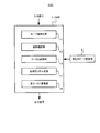
- FIG. 2 is a block diagram illustrating a schematic configuration of the playback apparatus 100 according to the first embodiment.
- the playback device 100 is a device that performs control for playing back audio signals and the like.
- the playback apparatus 100 reads an audio signal stored in a storage medium such as a CD (Compact Disk), a DVD (Digital Versatile Disk), or a BD (Blu-ray Disc) (not shown) and processes the audio signal.
- the signal after the output is output as a reproduction signal.
- the playback apparatus 100 mainly includes a DSP (Digital Signal Processor) 1 and a playback speed setting unit 2. Note that the playback apparatus 100 actually has other components than the DSP 1 and the playback speed setting unit 2, but for convenience of explanation, only the components related to the control of this embodiment are shown in FIG. .
- DSP Digital Signal Processor
- the DSP 1 receives a signal (specifically, an audio signal) after a predetermined process is performed on a signal read from a storage medium, for example, and performs a tempo conversion on the input signal Is output. In this case, the DSP 1 performs tempo conversion according to the reproduction speed set by the reproduction speed setting unit 2 on the input signal.
- the playback speed setting unit 2 sets the playback speed according to the operation by the user, for example.
- the playback speed is, in other words, “playback tempo magnification”.
- the playback tempo is not changed (that is, set to the default playback tempo).
- the playback speed is less than “1”
- the playback tempo is slowed down, and the playback speed is “ If it is greater than “1”, the playback tempo is increased. In this case, the playback tempo is made slower or the playback tempo is made faster as the playback speed is further away from “1”.
- the DSP 1 includes a loop waveform forming unit 11, a waveform circulating unit 12, a Fourier transform unit 13, a phase randomization unit 14, and an inverse Fourier transform unit 15.
- a loop waveform forming unit 11 a waveform circulating unit 12
- a Fourier transform unit 13 a phase randomization unit 14
- an inverse Fourier transform unit 15 an inverse Fourier transform unit 15.
- the waveform having a predetermined length in the time axis direction cut out from the waveform corresponding to the input signal at a predetermined cycle is sequentially input to the loop waveform forming unit 11.
- the waveform is input to the loop waveform forming unit 11 from a waveform cutting means (not shown).
- the loop waveform forming unit 11 performs processing (hereinafter referred to as “loop waveform conversion”) for converting the waveform cut out in this way into a waveform that can be continuously and repeatedly reproduced (that is, a waveform that can be reproduced by a loop).
- the waveform circulator 12 circulates the waveform formed by the loop waveform generator 11 in accordance with the phase shift between the previously extracted waveform and the current extracted waveform (hereinafter referred to as “waveform circulation”). .)I do.
- the Fourier transform unit 13 performs a Fourier transform on the waveform circulated by the waveform circulator 12.
- the phase randomization unit 14 performs processing for randomizing the phase spectrum (hereinafter referred to as “phase randomization”) on the waveform subjected to the Fourier transform by the Fourier transform unit 13. Specifically, when the playback speed is less than “1”, the phase randomizing unit 14 performs a frequency domain on a waveform that has been Fourier-transformed according to the playback speed set by the playback speed setting unit 2. The process of randomizing the phase of each frequency in is performed.
- the inverse Fourier transform unit 15 performs an inverse Fourier transform on the waveform randomized by the phase randomization unit 14 and outputs a waveform after the inverse Fourier transform is performed.
- the loop waveform forming unit 11 corresponds to the loop waveform forming unit in the present invention
- the waveform circulating unit 12 corresponds to the waveform circulating unit in the present invention
- the phase randomizing unit 14 corresponds to the phase randomizing unit in the present invention.
- a waveform is cut out at a fixed point, and playback is performed by missing, duplicating or repeating a section delimited by the fixed point (see FIG. 1).
- Using such a method is equivalent to sampling the timbre at fixed point intervals. Therefore, for example, when the playback speed is slowed down, the sound may not change smoothly.
- a method is employed in which a waveform is cut out in a short time section from each reproduction point without providing a fixed point.
- the present embodiment employs a technique of sequentially cutting out a waveform having a predetermined length in the time axis direction from the input waveform every predetermined period. For example, the cycle of cutting out the waveform is shorter than the length of cutting out the waveform (interval for cutting out the waveform).
- a waveform obtained by cutting out the input original waveform is referred to as a “cutout waveform” as appropriate, and a section (in other words, a length of cutting out the waveform) for cutting out a waveform defined on the time axis is appropriately cut out. It is called “section” or simply “section”. Further, in this specification, the term “extracted waveform” is used not only for the waveform immediately after the input original waveform is extracted, but also for the waveform after various processing is performed on the waveform. Shall.
- the waveform circulator 12 in order to achieve smoother playback, when the playback of the previous section is relatively advanced, the phase by the amount advanced from the cut-out section in the playback of the previous section.
- the process of returning the phase by the amount delayed from the cut-out section in the playback of the previous section is performed.
- the waveform circulator 12 treats the cut-out section like a circular buffer, performs a process of turning the sample that has come out earlier by moving the phase backward, The sample that has come out behind due to the delay is turned forward.
- the “sample” here corresponds to sampling data constituting the cut-out waveform (the same shall apply hereinafter). Therefore, cutting out the waveform corresponds to extracting waveform data of a predetermined number of samples from the input signal.
- FIG. 3 (a) shows a diagram for explaining why it is desirable to advance the phase.
- FIG. 3A shows time in the horizontal direction.
- An example of the actual music signal is shown above, and an example of the reproduction signal in the cut-out section is shown below.
- the input signal is expressed as “x”, and one cutout section (one block) is expressed as “bs”.
- “N” is an arbitrary natural number and corresponds to a playback point.
- the reproduction signal for “x (n)” to “x (n + bs)” is generated by cutting out the waveform of the song “x (n + bs)” from “x (n)”, and “x (n + bs)”.
- ) ”To“ x (n + 2bs) ” is generated by cutting out the waveform of the song“ x (n + 3bs / 2) ”from“ x (n + bs / 2) ”.
- the reproduction signal is generated by extracting the information of the overlapping sections as described above, a phase shift tends to occur as indicated by reference numeral A1 in FIG. In this case, since smooth reproduction is not performed, it can be said that it is desirable to advance the phase of the reproduction signal.
- FIG. 3B is a diagram showing an example of waveform tour in this embodiment.
- the waveform circulator 12 uses the previous cut-out waveform (the waveform cut out for playing the previous section) as the current cut-out waveform (for playing back the subsequent section) in order to realize smooth playback. If the current cut-out waveform is relatively advanced from the previous cut-out waveform, in other words, if the current cut-out waveform is relatively behind the previous cut-out waveform, the phase of the current cut-out waveform is advanced by the amount of the phase shift. Process. FIG. 3B illustrates a case where the phase is advanced.
- the waveform circulator 12 moves the sample that has come out earlier by the advance of the phase when the phase is advanced in order to maintain the timbre (spectrum) in the extracted section.
- FIG. 3B illustrates a case where the sample B1 is rotated backward because the sample B1 comes out forward by advancing the phase.
- the waveform circulator 12 performs a process of turning the sample that has come out behind by delaying the phase forward. That is, when the phase of the cut-out waveform is delayed, the waveform circulator 12 extracts a back sample corresponding to the delayed phase in the cut-out waveform, and combines the extracted sample before the cut-out waveform.
- loop waveform Next, the loop waveform forming performed by the loop waveform forming unit 11 will be specifically described.
- the loop waveform forming unit 11 performs loop waveform conversion for converting the cut-out waveform into a continuously reproducible (loopable) state in order to suppress the occurrence of such discontinuous points. Do. That is, the loop waveform forming unit 11 performs a process of converting the sound in the cut-out section into the loop sound without changing the timbre (spectrum) as much as possible.
- the loop waveform forming unit 11 has a triangular window in which the values of the start point, the midpoint, and the end point on the time axis in the cut-out section are “0”, “1”, and “0”, respectively.
- a function in other words, a Bartlett window, hereinafter referred to as a “triangular window”
- a loop waveform is formed.
- the loop waveform forming unit 11 shifts the waveform obtained by multiplying the cutout waveform by a triangular window and the obtained waveform by a half cycle of the cycle corresponding to the cutout section ( A loop waveform is formed by adding the circulated waveform).
- the waveform circulating unit 12 performs the above-described processing on the waveform after the loop waveform forming unit 11 performs the loop waveform in this way.
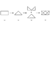
- FIG. 4A schematically shows a cut-out waveform.
- FIG. 4B schematically shows a waveform obtained by multiplying the cutout waveform by a triangular window.
- FIG. 4C shows a waveform obtained by multiplying a cutout waveform by a triangular window, and a waveform obtained by circulating the obtained waveform by a half period corresponding to the cutout section. The addition is schematically shown.
- FIG. 4D schematically shows a waveform obtained by the calculation shown in FIG. That is, the waveform after the loop waveform is formed on the cut-out waveform is schematically shown.
- the triangular window is not limited to using a window whose start point, middle point, and end point are “0”, “1”, and “0”. Moreover, it is not limited to using a triangular window when performing loop waveform formation, and a known window function other than the triangular window (for example, a Gaussian window) may be used.
- a known window function other than the triangular window for example, a Gaussian window
- phase randomization Next, the phase randomization performed by the phase randomization unit 14 will be specifically described.
- the information included in the musical sound of the cut-out section can be roughly divided into two types of information.
- One is a steady sound component (a pure sound component and a noise component with a constant amplitude)
- the other is a modulation component that creates an envelope (a change in sound intensity over time) and a frequency change.
- the steady sound component can be heard continuously even when the loop is played back, but the modulation component creates an envelope or the like, so that the period may be noticeable when the loop is played back.
- the processing of the cut waveform is relatively light, and the phase spectrum is randomized so that the amplitude spectrum shape does not change in the cut section.
- processing for converting the cut-out waveform into a steady sound is performed.
- the phase randomizing unit 14 performs a process of randomizing the phase of each frequency in the frequency region of the cut-out waveform according to the reproduction speed in the tempo conversion.
- the phase randomizing unit 14 performs a process of multiplying each frequency element by a vector whose length is “1” and whose phase is random according to the reproduction speed.
- the phase randomizing unit 14 does not perform randomization independently on the left and right signals of the stereo signal in order to maintain the stereo feeling. In this case, the phase randomizing unit 14 uses the same phase as the randomized phase in the left and right signals of the stereo signal.
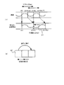
- FIG. 5 shows an example of the effect of phase randomization.
- FIG. 5A it can be seen that when phase randomization is performed, the waveform envelope collapses. Thereby, even if the reproduction speed is slowed down, the generation of sound according to the loop period as described above can be suppressed.
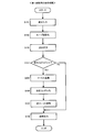
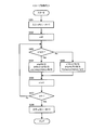
- FIG. 6 is a flowchart showing the overall processing of the first embodiment. This process is repeatedly executed by the DSP 1 at a predetermined cycle. In addition, a fixed value may be used for the predetermined period which performs the said process, and a variable may be used. For example, the cycle for performing the processing may be changed according to the reproduction speed or the like.
- step S101 the DSP 1 receives a waveform of a signal to be reproduced. Specifically, the DSP 1 receives waveform data having a predetermined length in the time axis direction from the waveform reading position, in other words, waveform data obtained by extracting a predetermined number of samples from the waveform reading position. Then, the process proceeds to step S102.
- step S102 the loop waveform generator 11 in the DSP 1 performs loop waveform conversion on the waveform input in step S101. Specifically, the loop waveform forming unit 11 performs processing for converting the cut waveform into a waveform that can be reproduced continuously and repeatedly using the triangular window as described above. Then, the process proceeds to step S103.
- step S103 the waveform circulation unit 12 in the DSP 1 performs waveform circulation on the waveform that has been converted into the loop waveform in step S102.
- the waveform circulator 12 is the sample difference between the read-out position of the cut-out waveform and the position where the cut-out waveform is to be output by the phase shift between the previously cut-out waveform and the current cut-out waveform. Only the loop waveform is circulated. Then, the process proceeds to step S104.
- step S104 the DSP 1 determines whether or not the reproduction speed (in other words, reproduction tempo magnification) is less than “1”. That is, the DSP 1 determines whether or not the playback speed setting unit 2 is set to slow down the playback speed. If the reproduction speed is less than “1” (step S104; Yes), the process proceeds to step S105. If the reproduction speed is “1” or more (step S104; No), the process proceeds to step S108.
- step S105 the Fourier transform unit 13 in the DSP 1 performs a Fourier transform on the waveform circulated in step S103. Then, the process proceeds to step S106.
- step S106 the phase randomizing unit 14 in the DSP 1 performs processing for randomizing the phase spectrum of the waveform subjected to Fourier transform in step S105. Specifically, the phase randomizing unit 14 performs a process of multiplying each frequency element of the Fourier-transformed waveform by a vector having a length of “1” and a phase that is random according to the reproduction speed. Then, the process proceeds to step S107.
- step S107 the inverse Fourier transform unit 15 in the DSP 1 performs inverse Fourier transform on the waveform phase-randomized in step S106. Then, the process proceeds to step S108.
- step S108 the DSP 1 outputs the waveform that has been subjected to the inverse Fourier transform in step S107. Then, the process ends.
- the tempo conversion with the pitch held is performed. For example, by repeatedly cutting out the waveform in the overlapping section and performing the above processing on the extracted waveform in order to reproduce the output waveform sequentially, the playback speed was slowed down and slowed down. The signal will be reproduced.
- step S102 the processing performed in the loop waveform formation in step S102, the waveform circulation in step S103, and the phase randomization in step S106 will be described more specifically.
- FIG. 7 is a flowchart showing loop waveform formation performed in step S102 described above. This flow is executed by the loop waveform forming unit 11 in the DSP 1.
- step S201 the loop waveform forming unit 11 acquires an input signal x (0, 1,..., N ⁇ 1) of N samples corresponding to the waveform input in step S101. Then, the process proceeds to step S202.
- N corresponds to the number of sampling data when a waveform is cut out, in other words, corresponds to the number of waveform data constituting the cut-out waveform, and is a value that defines one cut-out section (one block) (the same applies hereinafter). And).
- step S202 the loop waveform forming unit 11 sets the counter n to “0”, that is, performs initialization.
- the counter n indicates a playback point (hereinafter the same). Thereafter, the process proceeds to step S203.
- step S203 the loop waveform forming unit 11 determines whether or not the counter n is smaller than “N / 2”. This determination is performed in order to execute processing for the cut waveform by dividing the half cycle of the cut section. If “n ⁇ N / 2” (step S203; Yes), the process proceeds to step S204. If “n ⁇ N / 2” is not satisfied (step S203; No), that is, “n ⁇ N / 2”. If so, the process proceeds to step S205.
- step S204 is performed in the first half cycle of the cutout section
- step S205 is performed in the second half cycle of the cutout section.
- the loop waveform forming unit 11 obtains coefficients a and b based on the counter n and the number of samples N, and multiplies the input signal x (n) by the coefficient a.
- the output signal y (n) is calculated by adding the value obtained by multiplying the value obtained by multiplying the coefficient b by the signal whose phase of the input signal x (n) is shifted.
- step S204 and S205 the process proceeds to step S206.
- step S207 the loop waveform forming unit 11 determines whether or not the counter n matches the number of samples N. If the counter n matches the number of samples N (step S207; Yes), the process proceeds to step S208. In this case, the loop waveform forming unit 11 outputs the output signal y (0, 1,..., N ⁇ 1) calculated in steps S204 and S205 (step S208). Then, the process ends. On the other hand, when the counter n does not match the sample number N (step S207; No), the process returns to step S203. In this case, the processes in steps S203 to S207 are repeated until the counter n matches the number N of samples.
- FIG. 8 is a flowchart showing the waveform tour performed in step S103 described above. This flow is executed by the waveform circulator 12 in the DSP 1.
- step S301 the waveform circulator 12 acquires an input signal x (0, 1,..., N ⁇ 1) of N samples.
- the input signal x corresponds to the signal that has been converted into a loop waveform by the loop waveform generator 11.
- an input signal used in waveform circulation is indicated by the same symbol “x” as the input signal shown in the loop waveform.
- step S302 the waveform circulator 12 sets the counter n to “0”, that is, performs initialization. Then, the process proceeds to step S303.
- step S303 the waveform circulating unit 12 counts the counter n and the number k of samples to be cycled through the cutout waveform (corresponding to the phase shift between the previous cutout waveform and the current cutout waveform, hereinafter “waveform cyclic sample number k”). It is determined whether or not the value obtained by adding the number of samples is less than the number N of samples. This determination is performed to determine whether to output a waveform with the phase of the cutout waveform advanced or a waveform with a delayed phase, or to output a waveform generated by rotating the phase of the cutout waveform. For example, the waveform cyclic sample number k is set by comparing the waveform data at the readout position of the cutout waveform with the waveform data at the position where the cutout waveform is to be output.
- the waveform cyclic sample number k is a positive value
- the waveform cyclic sample number k is a negative value. Is a positive value obtained by subtracting the number of samples advanced from N. Therefore, k is a value from “0” to “N ⁇ 1”.
- step S304 the waveform circulator 12 obtains the input signal x (n + k) as the output signal y (n) (step S304). That is, the waveform cyclic unit 12 obtains a waveform obtained by advancing or delaying the phase of the cut-out waveform by the number of waveform cyclic samples k. Then, the process proceeds to step S306.
- the waveform cyclic output signal is indicated by the same sign “y” as the output signal shown in the loop waveform (the same applies hereinafter).
- step S303 if “n + k ⁇ N” is not satisfied (step S303; No), that is, if “n + k ⁇ N”, the process proceeds to step S305.
- the waveform circulator 12 obtains the input signal x (n + k ⁇ N) as the output signal y (n) (step S305). That is, the waveform circulating unit 12 obtains a waveform obtained by rotating the phase of the cut-out waveform forward or backward according to the number of waveform cyclic samples k. Then, the process proceeds to step S306.
- step S307 the waveform circulating unit 12 determines whether or not the counter n matches the number of samples N. If the counter n matches the number of samples N (step S307; Yes), the process proceeds to step S308. In this case, the waveform circulator 12 outputs the output signal y (0, 1,..., N ⁇ 1) calculated in steps S304 and S305 (step S308). Then, the process ends. On the other hand, when the counter n does not match the number of samples N (step S307; No), the process returns to step S303. In this case, the processes in steps S303 to S307 are repeated until the counter n matches the number N of samples.
- FIG. 9 is a flowchart showing the phase randomization performed in step S106 described above. This flow is executed by the phase randomizing unit 14 in the DSP 1.
- step S401 the phase randomization unit 14 obtains an input signal X (0, 1,..., N ⁇ 1) of N samples.
- the input signal X corresponds to a signal obtained by Fourier transforming the signal that has been subjected to waveform circulation by the waveform circulator 12 by the Fourier transformer 13.
- step S401 ends, the process proceeds to step S402.
- step S402 the phase randomizing unit 14 sets the counter n to “0”, that is, performs initialization. Then, the process proceeds to step S403.
- step S403 the phase randomizing unit 14 performs a process of randomizing the phase spectrum of the input signal X (n). Specifically, the phase randomizing unit 14 multiplies a random value in the range from “ ⁇ ” to “ ⁇ ” by a value obtained by subtracting the reproduction speed s from “1” to obtain “w”.
- the output signal Y (n) is obtained by multiplying the input signal X (n) by a complex number R having a length of “1” with the “w” as an argument. This corresponds to performing a process of multiplying each frequency element of the input waveform by a vector having a length of “1” and a phase that is random according to the reproduction speed s. Then, the process proceeds to step S404.
- step S405 the phase randomizing unit 14 determines whether or not the counter n matches “N / 2”. If the counter n matches “N / 2” (step S405; Yes), the process proceeds to step S406. In this case, the phase randomization unit 14 sets the output signal Y (N / 2, N / 2 + 1,..., N ⁇ 1) when n is “N / 2” or more to “0” (step S406). ). That is, the phase randomizing unit 14 sets the output signal Y in the second half of the cut-out section to “0”. This is to reduce the processing load. When S406 ends, the process proceeds to step S407.
- step S406 is not limited. That is, the determination in step S405 and the process of setting the output signal Y in step S406 to “0” may not be performed.
- step S407 the phase randomizing unit 14 outputs the output signal Y obtained in step S403 and the output signal Y set to “0” in step S406 together (step S407). Then, the process ends.
- step S405 if the counter n does not match “N / 2” (step S405; No), that is, if the counter n is less than “N / 2”, the process returns to step S403. In this case, the processes of steps S403 to S405 described above are repeated until the counter n matches “N / 2”.
- the phase is randomized when tempo conversion is performed, so that even if the tempo conversion is performed significantly, for example, the playback speed is considerably reduced, the reproduction sound quality is appropriately deteriorated. It becomes possible to suppress it. Specifically, it is possible to appropriately suppress the generation of a sound (beat sound) according to the loop period. That is, according to the present embodiment, it is possible to realize tempo conversion that is smoother and wider.
- the Fourier transform is performed after the waveform tour is performed.
- the second embodiment is different from the first embodiment in that the waveform tour is performed after the Fourier transform.
- processing is performed in the order of loop waveform formation, Fourier transform, and waveform circulation.
- the second embodiment is different from the first embodiment in that overlap processing is performed on the output waveform.
- processing in the second embodiment is also performed by the DSP 1 (see FIG. 2) in the playback apparatus 100 described above. Further, configurations and methods not specifically described here are the same as those in the first embodiment.
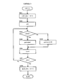
- FIG. 10 is a flowchart showing the overall processing of the second embodiment. This process is also repeatedly executed by the DSP 1 at a predetermined cycle. It should be noted that description of steps in which the same processing as the overall processing of the first embodiment (see FIG. 6) is performed will be omitted as appropriate.
- step S501 and S502 processing similar to that in steps S101 and S102 described above is performed.
- step S503 the Fourier transform unit 13 in the DSP 1 performs a Fourier transform on the waveform converted into the loop waveform in step S502. Then, the process proceeds to step S504.
- step S504 the waveform circulator 12 in the DSP 1 performs waveform circulation on the waveform subjected to Fourier transform in step S503.
- the waveform circulator 12 performs a waveform circulation process on the Fourier-transformed frequency axis. Specifically, the waveform circulator 12 performs a process of multiplying the cut waveform by “e j ⁇ kT ”. Note that “k” indicates the number of waveform cyclic samples, and “T” indicates the sampling period when the waveform is cut out.
- step S504 the process proceeds to step S505.
- step S505 the same determination as in step S104 described above is performed.
- step S506 the phase randomizing unit 14 in the DSP 1 performs phase randomization on the waveform that has undergone waveform circulation in step S504. Then, the process proceeds to step S507.
- step S507 the same processing as in step S107 described above is performed.
- step S508 the DSP 1 performs an overlap process on the waveform subjected to the inverse Fourier transform in step S507. Specifically, the DSP 1 performs a process of multiplying a waveform subjected to inverse Fourier transform by a predetermined overlap window (that is, a window function). For example, the DSP 1 multiplies the cut-out waveform by a predetermined overlap window so that the cut-out waveform rises smoothly in the previous overlap section and attenuates smoothly in the back overlap section. Thereby, the adjacent cut-out waveforms subjected to the overlap processing are overlapped and reproduced in the overlap period in the front-rear direction. Thereafter, the process proceeds to step S509. In step S509, the DSP 1 outputs the waveform subjected to the overlap processing in step S508. Then, the process ends.
- a predetermined overlap window that is, a window function
- phase randomization is performed only when the reproduction speed is less than “1” has been described.
- the phase randomization may be performed even when the reproduction speed is “1” or more.
- the present invention can be used for various audio playback apparatuses.
Landscapes
- Engineering & Computer Science (AREA)
- Computational Linguistics (AREA)
- Quality & Reliability (AREA)
- Signal Processing (AREA)
- Health & Medical Sciences (AREA)
- Audiology, Speech & Language Pathology (AREA)
- Human Computer Interaction (AREA)
- Physics & Mathematics (AREA)
- Acoustics & Sound (AREA)
- Multimedia (AREA)
- Electrophonic Musical Instruments (AREA)
Abstract
再生装置は、入力された信号に対してテンポ変換を行って再生する。再生装置は、入力された信号から波形を切り出す波形切り出し手段と、波形切り出し手段によって切り出された波形に対して、テンポ変換を行う再生スピードに応じて、位相をランダム化する処理を行う位相ランダム化手段と、を備える。当該再生装置によれば、テンポ変換に起因する音質劣化の発生を適切に抑制することが可能となる。
Description
本発明は、音声信号などに対してテンポ変換を行う技術分野に関する。
従来から、音声信号などのデジタル信号の時間軸を圧縮又は伸長する技術が知られている。つまり、音声信号などを再生する際の再生スピードを変化させる技術(以下、「テンポ変換」又は「タイムストレッチ」と呼ぶ。)が提案されている。また、デジタル信号のピッチを変えずにテンポ変換を行うことを図った技術が提案されている。これは、音程を保ちつつ楽曲の再生スピードを変化させることに相当する。
例えば、特許文献1には、原デジタル信号から切り出した波形の両端をクロスフェードさせながら結合することによりテンポ変換を行うこと、及び、切り出す波形の切り出し開始位置を、探索開始位置から探索終了位置までの間のクロスフェードされる波形同士が最も類似する位置に決定することが提案されている。また、特許文献2には、音声情報のテンポが変化させられても、音声情報のピッチを記憶媒体に記録されていた音声情報のピッチと同一にするようにピッチを変化させるか、または音声情報のピッチに変化を加えないことが提案されている。
しかしながら、上記した特許文献1及び2に記載された技術では、テンポ変換により時間軸を大幅に伸長した場合、例えば再生スピードをかなり遅くした場合に、切り出された波形の区間の繰り返し再生によるビート音が発生することで、再生音質が低下してしまう可能性があった。
本発明が解決しようとする課題としては、上記のものが一例として挙げられる。本発明は、テンポ変換に起因する音質劣化の発生を適切に抑制することが可能な再生装置、再生方法及び再生プログラムを提供することを目的とする。
請求項1に記載の発明は、入力された信号に対してテンポ変換を行って再生する再生装置である。再生装置は、前記入力された信号から、波形を切り出す波形切り出し手段と、前記波形切り出し手段によって切り出された波形に対して、前記テンポ変換を行う再生スピードに応じて、位相をランダム化する処理を行う位相ランダム化手段と、を備える。
請求項10に記載の発明は、入力された信号に対してテンポ変換を行って再生するための再生方法である。再生方法は、前記入力された信号から、波形を切り出す波形切り出し工程と、前記波形切り出し工程で切り出された波形に対して、前記テンポ変換を行う再生スピードに応じて、位相をランダム化する処理を行う位相ランダム化工程と、を備える。
請求項11に記載の発明は、コンピュータによって実行され、入力された信号に対してテンポ変換を行って再生するための再生プログラムである。再生プログラムは、前記コンピュータを、前記入力された信号から、波形を切り出す波形切り出し手段、前記波形切り出し手段によって切り出された波形に対して、前記テンポ変換を行う再生スピードに応じて、位相をランダム化する処理を行う位相ランダム化手段、として機能させる。
本発明の1つの観点では、入力された信号に対してテンポ変換を行って再生する再生装置は、前記入力された信号から、波形を切り出す波形切り出し手段と、前記波形切り出し手段によって切り出された波形に対して、前記テンポ変換を行う再生スピードに応じて、位相をランダム化する処理を行う位相ランダム化手段と、を備える。
上記の再生装置は、入力された信号に対してテンポ変換を行って再生するために、つまり再生スピードを変化させて音声信号などを再生するために好適に利用される。波形切り出し手段は、入力された信号から波形を切り出す。具体的には、波形切り出し手段は、連続する入力信号に対応する波形から、時間軸方向に所定の長さを有する波形を、所定の周期で繰り返し切り出す。なお、本明細書では「波形」とは、信号の形状などを意味するのではなく、時間的に連続する信号のデータを意味するものとする。
そして、位相ランダム化手段は、こうして切り出された波形に対して、テンポ変換を行う再生スピードに応じて、位相をランダム化する処理を行う。具体的には、位相ランダム化手段は、再生スピードに応じて、切り出された波形の周波数領域における各周波数の位相をランダム化する。これにより、テンポ変換に起因する音質劣化の発生を適切に抑制することが可能となる。例えば、ループの周期に応じた音(ビート音)の発生を適切に抑制することが可能となる。
上記の再生装置の一態様では、前記位相ランダム化手段は、前記切り出された波形に対して、長さが「1」で位相が前記再生スピードに応じてランダムなベクトルを乗算する処理を行う。
この態様では、位相ランダム化手段は、切り出された波形における各周波数エレメントに対して、長さが「1」で位相が再生スピードに応じてランダムなベクトルを乗じることで、位相ランダム化を行う。これにより、より滑らかで、より幅の広いテンポ変換を実現することが可能となる。
上記の再生装置の他の一態様では、前記位相ランダム化手段は、前記再生スピードが「1」未満である場合にのみ、前記ランダム化する処理を行う。
この態様では、再生スピードが「1」以上である場合には、位相をランダム化する処理を行わない。このように再生スピードに応じて選択的にランダム化を行うことで、処理負荷を軽減することができる。
上記の再生装置の他の一態様では、前記波形切り出し手段によって前回切り出された波形と前記波形切り出し手段によって今回切り出された波形との位相ずれに応じて、前記今回切り出された波形を巡回させる処理を行う波形巡回手段を更に備え、前記位相ランダム化手段は、前記波形巡回手段によって前記巡回させる処理が行われた後の波形に対して、前記ランダム化する処理を行う。
この態様によれば、切り出し波形に対して処理を施すことにより、位相を合わせて再生するのみの定常的な処理を行えば良いので、処理を簡略化することができる。例えば、クロスフェード位置(言い換えるとスムージング位置)や波形の切り出し位置などを考慮した適応的な処理を行わなくて済む。
上記の再生装置において好適には、前記波形巡回手段は、前記位相ずれ分だけ、前記今回切り出された波形の位相を進める処理又は遅らせる処理を行うと共に、前記今回切り出された波形において前記位相ずれ分に対応するサンプルを、前記今回切り出された波形の後ろ又は前に回す処理を行う。
好適な例では、前記位相ランダム化手段は、前記波形巡回手段によって前記巡回させる処理が行われた波形をフーリエ変換した波形に対して、前記ランダム化する処理を行う。
他の好適な例では、前記波形巡回手段は、前記切り出された波形をフーリエ変換した波形に対して、前記巡回させる処理を行う。
上記の再生装置の他の一態様では、前記切り出された波形を、連続で繰り返し再生可能な波形に変換する処理を行うループ波形化手段を更に備え、前記波形巡回手段は、前記ループ波形化手段によって前記変換する処理が行われた後の波形に対して、前記巡回させる処理を行う。
この態様によれば、巡回された波形の結合部分における不連続点の発生を抑制することができる。よって、周期的な雑音などの発生を適切に抑制することが可能となる。
上記の再生装置において好適には、前記ループ波形化手段は、前記切り出された波形に対して三角窓を乗算することで得られた波形と、前記波形切り出し手段が前記波形を切り出す区間に対応する周期の半周期分だけ、前記得られた波形を時間軸上で巡回させた波形とを加算することで、前記連続で繰り返し再生可能な波形を求める。
この場合、ループ波形化手段は、切り出し波形に対して三角窓を乗算することで得られた波形と、切り出し波形の時間方向の長さの半分だけ、当該得られた波形を時間軸上で巡回された波形とを加算することで、ループ波形化を行う。
本発明の他の観点では、入力された信号に対してテンポ変換を行って再生するための再生方法は、前記入力された信号から、波形を切り出す波形切り出し工程と、前記波形切り出し工程で切り出された波形に対して、前記テンポ変換を行う再生スピードに応じて、位相をランダム化する処理を行う位相ランダム化工程と、を備える。
本発明の他の観点では、コンピュータによって実行され、入力された信号に対してテンポ変換を行って再生するための再生プログラムは、前記コンピュータを、前記入力された信号から、波形を切り出す波形切り出し手段、前記波形切り出し手段によって切り出された波形に対して、前記テンポ変換を行う再生スピードに応じて、位相をランダム化する処理を行う位相ランダム化手段、として機能させる。
上記した再生方法及び再生プログラムによっても、テンポ変換に起因する音質劣化の発生を適切に抑制することが可能となる。
以下、図面を参照して本発明の好適な実施例について説明する。
<基本概念>
まず、本実施例の内容を述べる前に、本実施例の基本概念について簡単に説明する。
まず、本実施例の内容を述べる前に、本実施例の基本概念について簡単に説明する。
図1は、一般的に行われている、デジタル信号のピッチを変えずにテンポ変換(タイムストレッチ)を行う手法の一例を示す。一般的には、図1に示すように、再生すべき信号に対応する波形を所定の時間区間(A~G)に区切って、再生スピード(言い換えると「再生テンポ」である。以下同様とする。)を変化させるテンポ変換が行われる。具体的には、この手法では、再生時に当該区間のいずれかを欠落あるいは重複させることにより時間的に短縮することで再生スピードを速くすると共に、当該区間のいずれかを繰り返し再生することにより時間的に引き伸ばすことで再生スピードを遅くしている。
上記した手法の問題点としては、区間の欠落や重複や繰り返しを行う際に、例えばリズムなどの時間的に短い音の信号が欠落してしまったり、二重に再生されてしまったりすることが挙げられる。これは、再生スピードを元の再生スピードから変化させる度合いが大きいほど、つまりタイムストレッチを行う度合いが大きいほど、顕著になる傾向にあると考えられる。
本実施例では、このような一般的な手法を基本的には継承しつつ、より滑らかでより幅の広いタイムストレッチが実現されるような再生制御を行う、つまり、テンポ変換に起因する音質劣化の発生が適切に抑制されるような再生制御を行う。
<第1実施例>
次に、第1実施例について説明する。
次に、第1実施例について説明する。
(装置構成)
図2は、第1実施例に係る再生装置100の概略構成を示すブロック図である。
図2は、第1実施例に係る再生装置100の概略構成を示すブロック図である。
再生装置100は、音声信号などを再生するための制御を行う装置である。例えば、再生装置100は、図示しないCD(Compact Disk)やDVD(Digital Versatile Disc)やBD(Blu-ray Disc)などの記憶媒体に記憶された音声信号を読み取り、当該音声信号に対して処理を行った後の信号を再生信号として出力する。
図2に示すように、再生装置100は、主に、DSP(Digital Signal Processor)1及び再生スピード設定部2を有する。なお、再生装置100は、実際にはDSP1及び再生スピード設定部2以外の構成要素も有するが、説明の便宜上、図2には本実施例の制御に関係のある構成要素のみを図示している。
DSP1は、例えば記憶媒体から読み取られた信号などに対して所定の処理が行われた後の信号(具体的には音声信号)が入力され、入力された信号に対してテンポ変換を行った信号を出力する。この場合、DSP1は、入力された信号に対して、再生スピード設定部2によって設定された再生スピードに応じたテンポ変換を行う。再生スピード設定部2は、例えばユーザによる操作に応じた再生スピードに設定する。
なお、再生スピードは、言い換えると「再生テンポ倍率」である。再生スピードが「1」である場合には再生テンポは変化されず(つまりデフォルトの再生テンポに設定され)、再生スピードが「1」未満である場合には再生テンポが遅くされ、再生スピードが「1」より大きい場合には再生テンポが速くされる。この場合、再生スピードが「1」から離れていくほど、再生テンポがより遅くされる又は再生テンポがより早くされる。
具体的には、DSP1は、ループ波形化部11と、波形巡回部12と、フーリエ変換部13と、位相ランダム化部14と、逆フーリエ変換部15と、を備える。ここでは、DSP1内の各構成要素の説明を簡単に行う。
ループ波形化部11には、入力信号に対応する波形から所定の周期で切り出された、時間軸方向に所定の長さを有する波形が順次入力される。この場合、ループ波形化部11には、図示しない波形切り出し手段から、当該波形が入力される。ループ波形化部11は、このように切り出された波形を、連続で繰り返し再生可能な波形(つまりループ再生可能な波形)に変換する処理(以下、「ループ波形化」と呼ぶ。)を行う。
波形巡回部12は、前回切り出された波形と今回切り出された波形との位相ずれに応じて、ループ波形化部11でループ波形化された波形を巡回させる処理(以下、「波形巡回」と呼ぶ。)を行う。フーリエ変換部13は、波形巡回部12で波形巡回された波形に対してフーリエ変換を行う。
位相ランダム化部14は、フーリエ変換部13でフーリエ変換された波形に対して、その位相スペクトルをランダム化する処理(以下、「位相ランダム化」と呼ぶ。)を行う。具体的には、位相ランダム化部14は、再生スピードが「1」未満である場合に、再生スピード設定部2によって設定された再生スピードに応じて、フーリエ変換された波形に対して、周波数領域における各周波数の位相をランダム化する処理を行う。逆フーリエ変換部15は、位相ランダム化部14で位相ランダム化された波形に対して逆フーリエ変換を行い、逆フーリエ変換が行われた後の波形を出力する。
なお、ループ波形化部11は本発明におけるループ波形化手段に相当し、波形巡回部12は本発明における波形巡回手段に相当し、位相ランダム化部14は本発明における位相ランダム化手段に相当する。
(波形巡回)
次に、波形巡回部12が行う波形巡回について具体的に説明する。
次に、波形巡回部12が行う波形巡回について具体的に説明する。
一般的な手法においては、再生スピードを変化させるべく、固定ポイントで波形の切り出しを行い、固定ポイントで区切られた区間の欠落や重複や繰り返しを行うことで再生を実行する(図1参照)。このような手法を用いた場合、固定ポイントの間隔で音色がサンプリングされたことと等価となる。そのため、例えば再生スピードを遅くした場合において、滑らかに音が変化しなくなる可能性がある。
したがって、本実施例では、固定ポイントを設けずに、そのつどの再生ポイントから短い時間区間にて波形を切り出す手法を採用する。言い換えると、本実施例では、入力波形から、所定の周期ごとに、時間軸方向に所定の長さを有する波形を順次切り出す手法を採用する。例えば、波形を切り出す周期は、波形を切り出す長さ(波形を切り出す区間)よりも短い。
なお、以下では、入力された元の波形を切り出した波形を、適宜「切り出し波形」と呼び、時間軸上に規定される波形を切り出す区間(言い換えると波形を切り出す長さ)を、適宜「切り出し区間」又は単に「区間」と呼ぶ。また、本明細書では「切り出し波形」の文言は、入力された元の波形を切り出した直後の波形そのものだけでなく、当該波形に対して種々の処理を行った後の波形に対しても用いるものとする。
上記のような手法では、再生スピードを遅くした場合に、重複した区間の情報が取り出される傾向にある。そのため、滑らかに再生するといった観点より、一般的な手法のように単純に区間の欠落や繰り返しといった再生を行うべきではないと言える。よって、本実施例では、波形巡回部12は、より滑らかな再生を実現するべく、前区間の再生が相対的に進んでいる場合には、前区間の再生において切り出し区間より進んだ分だけ位相を進める処理を行うと共に、前区間の再生が相対的に遅れている場合には、前区間の再生において切り出し区間より遅れた分だけ位相を戻す処理を行う。
他方で、このように位相を制御する場合において、切り出し区間の音色(スペクトル)が変わらないようにすることが望ましいと言える。これを満たすべく、本実施例では、波形巡回部12は、切り出し区間をサーキュラバッファのように扱い、位相を進めたことにより前に出てしまったサンプルを後ろへ回す処理を行うと共に、位相を遅らせたことにより後ろへ出てしまったサンプルを前に回す処理を行う。ここでいう「サンプル」は、切り出し波形を構成するサンプリングデータに相当する(以下同様とする)。よって、波形を切り出すことは、入力信号から、所定数のサンプルの波形データを取り出すことに相当する。
次に、図3を参照して、本実施例における波形巡回について具体的に説明する。
図3(a)は、位相を進ませるのが望ましい理由を説明するための図を示す。図3(a)は、横方向に時間を示している。また、上に実際の楽曲の信号の一例を示し、下に切り出し区間における再生信号の一例を示している。ここでは、入力信号を「x」と表記し、1つの切り出し区間(1ブロック)を「bs」と表記している。また、「n」は任意の自然数であり、再生ポイントに対応する。
この場合、「x(n)」から「x(n+bs)」についての再生信号は、「x(n)」から「x(n+bs)」の楽曲の波形を切り出すことで生成され、「x(n+bs)」から「x(n+2bs)」についての再生信号は、「x(n+bs/2)」から「x(n+3bs/2)」の楽曲の波形を切り出すことで生成される。このように重複した区間の情報を取り出して再生信号を生成した場合には、図3(a)中の符号A1に示すように位相ずれが生じる傾向にある。この場合には、滑らかな再生が行われないため、再生信号の位相を進ませることが望ましいと言える。つまり、前の切り出し区間(「x(n)」から「x(n+bs)」の区間)の再生において、後の切り出し区間(「x(n+bs/2)」から「x(n+3bs/2)」の区間)より進んだサンプル分だけ、後の切り出し波形の位相を進めることが望ましいと言える。
図3(b)は、本実施例における波形巡回の一例を示す図である。本実施例では、波形巡回部12は、滑らかな再生を実現するために、前回の切り出し波形(前区間の再生のために切り出された波形)が今回の切り出し波形(後区間の再生のために切り出された波形)よりも相対的に進んでいる場合、言い換えると今回の切り出し波形が前回の切り出し波形よりも相対的に遅れている場合、その位相ずれ分だけ、今回の切り出し波形の位相を進める処理を行う。図3(b)では、位相を進める場合を例示している。他方で、波形巡回部12は、前回の切り出し波形が今回の切り出し波形よりも相対的に遅れている場合、言い換えると今回の切り出し波形が前回の切り出し波形よりも相対的に進んでいる場合、その位相ずれ分だけ、今回の切り出し波形の位相を遅らせる処理を行う。
更に、本実施例では、波形巡回部12は、切り出した区間における音色(スペクトル)を保持するために、位相を進めた場合には、位相を進めたことにより前に出てしまったサンプルを後ろへ回す処理を行う。つまり、波形巡回部12は、切り出し波形の位相を進めた場合に、当該切り出し波形において位相を進めた分に相当する前のサンプルを摘出して、摘出したサンプルを当該切り出し波形の後ろに結合する処理を行う。図3(b)では、位相を進めることによりサンプルB1が前に出てしまうことから、当該サンプルB1を後ろへ回す場合を例示している。他方で、波形巡回部12は、位相を遅らせた場合には、位相を遅らせたことにより後ろに出てしまったサンプルを前へ回す処理を行う。つまり、波形巡回部12は、切り出し波形の位相を遅らせた場合に、当該切り出し波形において位相を遅らせた分に相当する後ろのサンプルを摘出して、摘出したサンプルを当該切り出し波形の前に結合する処理を行う。
(ループ波形化)
次に、ループ波形化部11が行うループ波形化について具体的に説明する。
次に、ループ波形化部11が行うループ波形化について具体的に説明する。
上記したように波形巡回を行った場合、具体的にはサンプルを後ろに回す処理又は前に回す処理を行った場合、後ろに回ったサンプルのポイント又は前に回ったサンプルのポイントにおいて(つまり摘出したサンプルを結合したポイントにおいて)、不連続点が生じてしまう可能性がある。不連続点が生じた場合には、周期的に雑音が発生するおそれがある。
したがって、本実施例では、ループ波形化部11は、このような不連続点の発生を抑制するべく、切り出し波形を連続で繰り返し再生可能(ループ可能)な状態に変換するためのループ波形化を行う。つまり、ループ波形化部11は、音色(スペクトル)をなるべく変化させずに、切り出し区間における音をループ音に変換する処理を行う。
具体的には、ループ波形化部11は、切り出し区間においての時間軸上における始点、中点、及び終点のそれぞれの値が「0」、「1」、「0」である三角形状を有する窓関数(言い換えるとバートレット窓であり、以下では「三角窓」と呼ぶ。)を用いて、ループ波形化を行う。詳しくは、ループ波形化部11は、切り出し波形に対して三角窓を乗算することで得られた波形と、当該得られた波形を、切り出し区間に対応する周期の半周期分だけずらした波形(巡回させた波形)とを加算することで、ループ波形化を行う。なお、波形巡回部12は、このようにループ波形化部11がループ波形化を行った後の波形に対して、上記した処理を行う。
次に、図4を参照して、本実施例におけるループ波形化について具体的に説明する。図4(a)は、切り出し波形を模式的に示している。図4(b)は、切り出し波形に対して三角窓を乗算することで得られた波形を模式的に示している。図4(c)は、切り出し波形に対して三角窓を乗算することで得られた波形と、当該得られた波形を、切り出し区間に対応する周期の半周期分だけ巡回させた波形と、を加算することを模式的に示している。図4(d)は、図4(c)に示す演算により得られた波形を模式的に示している。つまり、切り出し波形に対してループ波形化を行った後の波形を模式的に示している。
なお、三角窓として、始点、中点、及び終点のそれぞれの値が「0」、「1」、「0」である窓を用いることに限定はされない。また、ループ波形化を行う際に三角窓を用いることに限定はされず、三角窓以外の公知の窓関数(例えばガウス窓など)を用いても良い。
(位相ランダム化)
次に、位相ランダム化部14が行う位相ランダム化について具体的に説明する。
次に、位相ランダム化部14が行う位相ランダム化について具体的に説明する。
再生スピードをかなり遅くした場合には、上記したようにループ波形化及び波形巡回を行った波形を用いた場合にも、ループの周期に応じた音が聴こえてしまう可能性がある。ここで、切り出し区間の楽音に含まれる情報としては、大きく分けると2種類の情報が考えられる。1つは、定常音成分(振幅が一定な純音成分とノイズ成分)であり、もう1つは、エンベロープ(音の時間的な強弱の変化)や周波数変化を作り出す変調成分である。定常音成分はループ再生しても連続的に聴こえるため問題はないが、変調成分はエンベロープ等を作るため、ループ再生するとその周期が目立って聴こえてしまう場合がある。
このような不具合は、切り出し区間の楽音情報から変調成分を取り除けば解決できると考えられるが、スペクトル等から定常音成分と変調成分とを分離することは困難である。また、たとえ変調成分が抜き出せたとしても、変調成分を削ることでスペクトル形状が変化することにより、音色に大きな影響を与えてしまう可能性があると考えられる。
したがって、本実施例では、切り出し波形に対して、処理が比較的軽く、切り出し区間において振幅スペクトル形状が変化しない、位相スペクトルのランダム化を行う。言い換えると、本実施例では、切り出し波形を定常音化する処理を行う。具体的には、位相ランダム化部14は、テンポ変換における再生スピードに応じて、切り出し波形の周波数領域における各周波数の位相をランダム化する処理を行う。詳しくは、位相ランダム化部14は、各周波数エレメントに対して、長さが「1」で位相が再生スピードに応じてランダムなベクトルを乗算する処理を行う。
なお、位相ランダム化部14は、再生すべき信号がステレオ信号である場合には、ステレオ感を保持するために、ステレオ信号の左右の信号に対して独立にランダム化を行わない。この場合、位相ランダム化部14は、ステレオ信号の左右の信号において、ランダム化した位相として同じ位相を用いる。
ここで、図5を参照して、本実施例における位相ランダム化による作用を具体的に説明する。図5は、位相ランダム化による作用の一例を示している。図5(a)に示すように、位相ランダム化を行った場合には、波形のエンベロープが崩れることがわかる。これにより、再生スピードを遅くしたとしても、上記したようなループの周期に応じた音の発生を抑制することができる。
また、図5(b)に示すように、位相ランダム化を行った場合には、切り出し区間において振幅スペクトル(言い換えると周波数特性)が変化しないことがわかる。
(第1実施例の処理)
次に、図6乃至図9を参照して、第1実施例においてDSP1が行う処理を具体的に説明する。
次に、図6乃至図9を参照して、第1実施例においてDSP1が行う処理を具体的に説明する。
図6は、第1実施例の全体処理を示すフローチャートである。この処理は、DSP1によって所定の周期で繰り返し実行される。なお、当該処理を行う所定の周期は、一定値を用いても良いし、変数を用いても良い。例えば、再生スピードなどに応じて、当該処理を行う周期を変えても良い。
まず、ステップS101では、DSP1は、再生すべき信号の波形が入力される。具体的には、DSP1は、波形の読み出し位置から時間軸方向に所定の長さを有する波形のデータ、言い換えると波形の読み出し位置から所定数のサンプルを抽出した波形データが入力される。そして、処理はステップS102に進む。
ステップS102では、DSP1内のループ波形化部11が、ステップS101で入力された波形に対してループ波形化を行う。具体的には、ループ波形化部11は、上記したような三角窓を用いて、切り出し波形を連続で繰り返し再生可能な波形に変換する処理を行う。そして、処理はステップS103に進む。
ステップS103では、DSP1内の波形巡回部12が、ステップS102でループ波形化された波形に対して波形巡回を行う。具体的には、波形巡回部12は、前回切り出された波形と今回切り出された波形との位相ずれ分だけ、つまり切り出し波形についての読み出し位置と切り出し波形を出力すべき位置との間におけるサンプル分だけ、ループ波形化された波形を巡回させる処理を行う。そして、処理はステップS104に進む。
ステップS104では、DSP1は、再生スピード(言い換えると再生テンポ倍率)が「1」未満であるか否かを判定する。つまり、DSP1は、再生スピード設定部2によって再生スピードを遅くするように設定されているか否かを判定する。再生スピードが「1」未満である場合(ステップS104;Yes)、処理はステップS105に進み、再生スピードが「1」以上である場合(ステップS104;No)、処理はステップS108に進む。
ステップS105では、DSP1内のフーリエ変換部13が、ステップS103で波形巡回された波形に対してフーリエ変換を行う。そして、処理はステップS106に進む。
ステップS106では、DSP1内の位相ランダム化部14が、ステップS105でフーリエ変換された波形に対して、その位相スペクトルをランダム化する処理を行う。具体的には、位相ランダム化部14は、フーリエ変換された波形の各周波数エレメントに対して、長さが「1」で位相が再生スピードに応じてランダムなベクトルを乗算する処理を行う。そして、処理はステップS107に進む。
ステップS107では、DSP1内の逆フーリエ変換部15が、ステップS106で位相ランダム化された波形に対して逆フーリエ変換を行う。そして、処理はステップS108に進む。ステップS108では、DSP1は、ステップS107で逆フーリエ変換された波形を出力する。そして、処理は終了する。
このようなフローを繰り返し行うことで、ピッチが保持されたテンポ変換が行われることとなる。例えば、重複した区間の波形を繰り返し切り出していき、切り出された波形に対して上記の処理を行うことで出力された波形を順次再生することで、時間的に引き伸ばされて再生スピードが遅くなった信号が再生されることとなる。
以下では、ステップS102のループ波形化、ステップS103の波形巡回、及びステップS106の位相ランダム化において行われる処理を、より具体的に説明する。
(1)ループ波形化の処理
図7は、上記したステップS102で行われるループ波形化を示すフローチャートである。このフローは、DSP1内のループ波形化部11によって実行される。
図7は、上記したステップS102で行われるループ波形化を示すフローチャートである。このフローは、DSP1内のループ波形化部11によって実行される。
ステップS201では、ループ波形化部11は、上記のステップS101で入力された波形に対応する、Nサンプルの入力信号x(0,1,…,N-1)を取得する。そして、処理はステップS202に進む。なお、「N」は、波形を切り出す場合のサンプリングデータ数に相当し、言い換えると切り出し波形を構成する波形データ数に相当し、1つの切り出し区間(1ブロック)を規定する値である(以下同様とする)。
ステップS202では、ループ波形化部11は、カウンタnを「0」に設定する、つまり初期化を行う。カウンタnは、再生ポイントを示している(以下同様とする)。この後、処理はステップS203に進む。
ステップS203では、ループ波形化部11は、カウンタnが「N/2」よりも小さいか否かを判定する。当該判定は、切り出し区間の半周期で分けて切り出し波形に対する処理を実行するために行っている。「n<N/2」である場合(ステップS203;Yes)、処理はステップS204に進み、「n<N/2」でない場合(ステップS203;No)、つまり「n≧N/2」である場合、処理はステップS205に進む。
ステップS204の処理は、切り出し区間の前半の半周期において行われ、ステップS205の処理は、切り出し区間の後半の半周期において行われる。ステップS204、S205のそれぞれにおいては、ループ波形化部11は、カウンタn及びサンプル数Nに基づいて係数a、bを求めて、当該係数aを入力信号x(n)に乗算することで得られた値と、当該係数bを入力信号x(n)の位相をずらした信号に乗算することで得られた値とを加算することで、出力信号y(n)を算出する。こうすることは、切り出し波形に対して三角窓を乗算することで得られた波形と、当該得られた波形を、切り出し区間における半周期分だけずらした波形(言い換えると、当該得られた波形を、「N/2」だけ時間軸方向に巡回させた波形)とを加算することに相当する。ステップS204、S205が終了すると、処理はステップS206に進む。
ステップS206では、ループ波形化部11は、カウンタnをインクリメントする(n=n+1)。そして、処理はステップS207に進む。ステップS207では、ループ波形化部11は、カウンタnがサンプル数Nに一致したか否かを判定する。カウンタnがサンプル数Nに一致した場合(ステップS207;Yes)、処理はステップS208に進む。この場合、ループ波形化部11は、ステップS204及びステップS205で算出された出力信号y(0,1,…,N-1)を出力する(ステップS208)。そして、処理は終了する。これに対して、カウンタnがサンプル数Nに一致していない場合(ステップS207;No)、処理はステップS203に戻る。この場合には、カウンタnがサンプル数Nに一致するまで、上記したステップS203~S207の処理を繰り返し行う。
(2)波形巡回の処理
図8は、上記したステップS103で行われる波形巡回を示すフローチャートである。このフローは、DSP1内の波形巡回部12によって実行される。
図8は、上記したステップS103で行われる波形巡回を示すフローチャートである。このフローは、DSP1内の波形巡回部12によって実行される。
ステップS301では、波形巡回部12は、Nサンプルの入力信号x(0,1,…,N-1)を取得する。この入力信号xは、ループ波形化部11によってループ波形化された信号に対応する。ここでは、説明の便宜上、ループ波形化で示した入力信号と同一の符号「x」によって、波形巡回で用いる入力信号を示している。ステップS301が終了すると、処理はステップS302に進む。
ステップS302では、波形巡回部12は、カウンタnを「0」に設定する、つまり初期化を行う。そして、処理はステップS303に進む。
ステップS303では、波形巡回部12は、カウンタnと、切り出し波形を巡回させるべきサンプル数k(前回の切り出し波形と今回の切り出し波形との位相ずれに相当し、以下では「波形巡回サンプル数k」と呼ぶ。)とを加算した値が、サンプル数N未満であるか否かを判定する。当該判定は、切り出し波形の位相を進めた波形又は位相を遅らせた波形を出力すべきか、或いは、切り出し波形の位相を回すことで生成される波形を出力すべきかを判断するために行っている。例えば、波形巡回サンプル数kは、切り出し波形の読み出し位置における波形データと、切り出し波形を出力すべき位置における波形データとを比較することで設定される。
なお、切り出し波形の位相を遅らせる場合には波形巡回サンプル数kは正値となり、切り出し波形の位相を進める場合には波形巡回サンプル数kは負値となるが、Nサンプルで巡回するため、kはNから進めるサンプル数を減算した正の値を取ることとする。よって、kは「0」から「N-1」の値である。
「n+k<N」である場合(ステップS303;Yes)、処理はステップS304に進む。この場合には、波形巡回部12は、入力信号x(n+k)を出力信号y(n)として求める(ステップS304)。つまり、波形巡回部12は、切り出し波形の位相を、波形巡回サンプル数kだけ進めた波形又は遅らせた波形を求める。そして、処理はステップS306に進む。なお、ここでは、説明の便宜上、ループ波形化で示した出力信号と同一の符号「y」によって、波形巡回の出力信号を示している(以下同様とする)。
これに対して、「n+k<N」でない場合(ステップS303;No)、つまり「n+k≧N」である場合、処理はステップS305に進む。この場合には、波形巡回部12は、入力信号x(n+k-N)を出力信号y(n)として求める(ステップS305)。つまり、波形巡回部12は、波形巡回サンプル数kに応じて、切り出し波形の位相を前又は後ろに回した波形を求める。そして、処理はステップS306に進む。
ステップS306では、波形巡回部12は、カウンタnをインクリメントする(n=n+1)。そして、処理はステップS307に進む。ステップS307では、波形巡回部12は、カウンタnがサンプル数Nに一致したか否かを判定する。カウンタnがサンプル数Nに一致した場合(ステップS307;Yes)、処理はステップS308に進む。この場合、波形巡回部12は、ステップS304及びステップS305で算出された出力信号y(0,1,…,N-1)を出力する(ステップS308)。そして、処理は終了する。これに対して、カウンタnがサンプル数Nに一致していない場合(ステップS307;No)、処理はステップS303に戻る。この場合には、カウンタnがサンプル数Nに一致するまで、上記したステップS303~S307の処理を繰り返し行う。
(3)位相ランダム化の処理
図9は、上記したステップS106で行われる位相ランダム化を示すフローチャートである。このフローは、DSP1内の位相ランダム化部14によって実行される。
図9は、上記したステップS106で行われる位相ランダム化を示すフローチャートである。このフローは、DSP1内の位相ランダム化部14によって実行される。
ステップS401では、位相ランダム化部14は、Nサンプルの入力信号X(0,1,…,N-1)を取得する。この入力信号Xは、フーリエ変換部13が、波形巡回部12で波形巡回された信号をフーリエ変換した信号に対応する。ステップS401が終了すると、処理はステップS402に進む。
ステップS402では、位相ランダム化部14は、カウンタnを「0」に設定する、つまり初期化を行う。そして、処理はステップS403に進む。
ステップS403では、位相ランダム化部14は、入力信号X(n)の位相スペクトルをランダム化する処理を行う。具体的には、位相ランダム化部14は、「-π」から「π」までの範囲内にあるランダムな値に、「1」から再生スピードsを減算した値を乗算することで「w」を求め、この「w」を偏角として長さが「1」である複素数Rを入力信号X(n)に対して乗算することで出力信号Y(n)を求める。これは、入力された波形の各周波数エレメントに対して、長さが「1」で位相が再生スピードsに応じてランダムなベクトルを乗算する処理を行うことに相当する。そして、処理はステップS404に進む。
ステップS404では、位相ランダム化部14は、カウンタnをインクリメントする(n=n+1)。そして、処理はステップS405に進む。
ステップS405では、位相ランダム化部14は、カウンタnが「N/2」に一致したか否かを判定する。カウンタnが「N/2」に一致した場合(ステップS405;Yes)、処理はステップS406に進む。この場合、位相ランダム化部14は、nが「N/2」以上であるときの出力信号Y(N/2,N/2+1,…,N-1)を「0」に設定する(ステップS406)。つまり、位相ランダム化部14は、切り出し区間の後半の半周期における出力信号Yを「0」に設定する。こうしているのは、処理負荷を軽減するためである。S406が終了すると、処理はステップS407に進む。
なお、ステップS406の処理を行うことに限定はされない。つまり、ステップS405の判定、及びステップS406における出力信号Yを「0」に設定する処理を行わなくても良い。
ステップS407では、位相ランダム化部14は、ステップS403で求められた出力信号Y及びステップS406で「0」に設定された出力信号Yを合わせて出力する(ステップS407)。そして、処理は終了する。
一方で、カウンタnが「N/2」に一致していない場合(ステップS405;No)、つまりカウンタnが「N/2」未満である場合、処理はステップS403に戻る。この場合には、カウンタnが「N/2」に一致するまで、上記したステップS403~S405の処理を繰り返し行う。
(第1実施例の効果)
以上説明した第1実施例によれば、テンポ変換を行う場合に位相をランダム化することにより、大幅なテンポ変換を行っても、例えば再生スピードをかなり遅くしても、再生音質の劣化を適切に抑制することが可能となる。具体的には、ループの周期に応じた音(ビート音)の発生を適切に抑制することが可能となる。つまり、本実施例によれば、より滑らかで、より幅の広いテンポ変換を実現することが可能となる。
以上説明した第1実施例によれば、テンポ変換を行う場合に位相をランダム化することにより、大幅なテンポ変換を行っても、例えば再生スピードをかなり遅くしても、再生音質の劣化を適切に抑制することが可能となる。具体的には、ループの周期に応じた音(ビート音)の発生を適切に抑制することが可能となる。つまり、本実施例によれば、より滑らかで、より幅の広いテンポ変換を実現することが可能となる。
また、第1実施例では、切り出し波形に処理を施すことにより、位相を合わせて(波形巡回させて)再生するのみの定常的な処理を行えば良いので、処理を簡略化することができる。具体的には、前述した特許文献1及び2に記載された技術では、実用上においては、クロスフェード位置(スムージング位置)や波形の切り出し位置などを考慮した適応的な処理が必要であると考えられるが、本実施例では、定常的な処理で済むため、このような適応的な処理を省くことができる。
<第2実施例>
次に、第2実施例について説明する。第1実施例では、波形巡回を行った後にフーリエ変換を行っていたが、第2実施例では、フーリエ変換を行った後に波形巡回を行う点で、第1実施例と異なる。具体的には、第2実施例では、ループ波形化、フーリエ変換、波形巡回の順で処理を行う。また、第2実施例では、出力波形に対してオーバーラップ処理を行う点で第1実施例と異なる。
次に、第2実施例について説明する。第1実施例では、波形巡回を行った後にフーリエ変換を行っていたが、第2実施例では、フーリエ変換を行った後に波形巡回を行う点で、第1実施例と異なる。具体的には、第2実施例では、ループ波形化、フーリエ変換、波形巡回の順で処理を行う。また、第2実施例では、出力波形に対してオーバーラップ処理を行う点で第1実施例と異なる。
なお、第2実施例における処理も、上記した再生装置100内のDSP1(図2参照)が行うものとする。また、ここで特に説明しない構成や手法などについては、第1実施例と同様であるものとする。
図10は、第2実施例の全体処理を示すフローチャートである。この処理も、DSP1によって所定の周期で繰り返し実行される。なお、ここでは、第1実施例の全体処理(図6参照)と同様の処理が行われるステップについては、その説明を適宜省略するものとする。
ステップS501及びS502では、上記したステップS101及びS102と同様の処理が行われる。ステップS503では、DSP1内のフーリエ変換部13が、ステップS502でループ波形化された波形に対してフーリエ変換を行う。そして、処理はステップS504に進む。
ステップS504では、DSP1内の波形巡回部12が、ステップS503でフーリエ変換された波形に対して波形巡回を行う。この場合、波形巡回部12は、フーリエ変換された周波数軸上において波形巡回の処理を行う。具体的には、波形巡回部12は、切り出し波形に対して「ejωkT」を乗算する処理を行う。なお、「k」は波形巡回サンプル数を示しており、「T」は波形を切り出す場合のサンプリング周期を示している。
ステップS504の後、処理はステップS505に進む。ステップS505では、上記したステップS104と同様の判定が行われる。ステップS506では、DSP1内の位相ランダム化部14が、ステップS504で波形巡回された波形に対して位相ランダム化を行う。そして、処理はステップS507に進む。ステップS507では、上記したステップS107と同様の処理が行われる。
ステップS508では、DSP1は、ステップS507で逆フーリエ変換された波形に対してオーバーラップ処理を行う。具体的には、DSP1は、逆フーリエ変換された波形に対して所定のオーバーラップ窓(つまり窓関数)を乗算する処理を行う。例えば、DSP1は、切り出し波形が前のオーバーラップ区間で滑らかに立ち上がると共に後ろのオーバーラップ区間で滑らかに減衰するように、切り出した波形に対して所定のオーバーラップ窓を乗算する。これにより、オーバーラップ処理された隣り合う切り出し波形が前後方向のオーバーラップ期間において重ね合わされて再生されることとなる。この後、処理はステップS509に進む。ステップS509では、DSP1は、ステップS508でオーバーラップ処理された波形を出力する。そして、処理は終了する。
以上説明した第2実施例によっても、テンポ変換に起因する音質劣化の発生を適切に抑制することが可能となる。
<変形例>
上記では、ループ波形化、波形巡回、及び位相ランダム化の全てを行う実施例を示したが、これに限定はされない。他の例では、ループ波形化及び波形巡回を行わずに、位相ランダム化のみを行うこととすることができる。この例では、切り出し波形に対して、その位相をランダム化する処理のみを行う。更に他の例では、ループ波形化を行わずに波形巡回のみを行い、波形巡回の後に位相ランダム化を行うこととすることができる。これらの他の例によっても、テンポ変換に起因する音質劣化の発生を抑制することができる。
上記では、ループ波形化、波形巡回、及び位相ランダム化の全てを行う実施例を示したが、これに限定はされない。他の例では、ループ波形化及び波形巡回を行わずに、位相ランダム化のみを行うこととすることができる。この例では、切り出し波形に対して、その位相をランダム化する処理のみを行う。更に他の例では、ループ波形化を行わずに波形巡回のみを行い、波形巡回の後に位相ランダム化を行うこととすることができる。これらの他の例によっても、テンポ変換に起因する音質劣化の発生を抑制することができる。
また、上記では、再生スピードが「1」未満である場合にのみ位相ランダム化を行う実施例を示したが、再生スピードが「1」以上である場合にも位相ランダム化を行っても良い。
本発明は、種々のオーディオ再生装置に利用することができる。
1 DSP
2 再生スピード設定部
11 ループ波形化部
12 波形巡回部
13 フーリエ変換部
14 位相ランダム化部
15 逆フーリエ変換部
100 再生装置
2 再生スピード設定部
11 ループ波形化部
12 波形巡回部
13 フーリエ変換部
14 位相ランダム化部
15 逆フーリエ変換部
100 再生装置
Claims (11)
- 入力された信号に対してテンポ変換を行って再生する再生装置であって、
前記入力された信号から、波形を切り出す波形切り出し手段と、
前記波形切り出し手段によって切り出された波形に対して、前記テンポ変換を行う再生スピードに応じて、位相をランダム化する処理を行う位相ランダム化手段と、を備えることを特徴とする再生装置。 - 前記位相ランダム化手段は、前記切り出された波形に対して、長さが「1」で位相が前記再生スピードに応じてランダムなベクトルを乗算する処理を行うことを特徴とする請求項1に記載の再生装置。
- 前記位相ランダム化手段は、前記再生スピードが「1」未満である場合にのみ、前記ランダム化する処理を行うことを特徴とする請求項1又は2に記載の再生装置。
- 前記波形切り出し手段によって前回切り出された波形と前記波形切り出し手段によって今回切り出された波形との位相ずれに応じて、前記今回切り出された波形を巡回させる処理を行う波形巡回手段を更に備え、
前記位相ランダム化手段は、前記波形巡回手段によって前記巡回させる処理が行われた後の波形に対して、前記ランダム化する処理を行うことを特徴とする請求項1乃至3のいずれか一項に記載の再生装置。 - 前記波形巡回手段は、前記位相ずれ分だけ、前記今回切り出された波形の位相を進める処理又は遅らせる処理を行うと共に、前記今回切り出された波形において前記位相ずれ分に対応するサンプルを、前記今回切り出された波形の後ろ又は前に回す処理を行うことを特徴とする請求項4に記載の再生装置。
- 前記位相ランダム化手段は、前記波形巡回手段によって前記巡回させる処理が行われた波形をフーリエ変換した波形に対して、前記ランダム化する処理を行うことを特徴とする請求項4又は5に記載の再生装置。
- 前記波形巡回手段は、前記切り出された波形をフーリエ変換した波形に対して、前記巡回させる処理を行うことを特徴とする請求項4又は5に記載の再生装置。
- 前記切り出された波形を、連続で繰り返し再生可能な波形に変換する処理を行うループ波形化手段を更に備え、
前記波形巡回手段は、前記ループ波形化手段によって前記変換する処理が行われた後の波形に対して、前記巡回させる処理を行うことを特徴とする請求項4乃至7のいずれか一項に記載の再生装置。 - 前記ループ波形化手段は、前記切り出された波形に対して三角窓を乗算することで得られた波形と、前記波形切り出し手段が前記波形を切り出す区間に対応する周期の半周期分だけ、前記得られた波形を時間軸上で巡回させた波形とを加算することで、前記連続で繰り返し再生可能な波形を求めることを特徴とする請求項8に記載の再生装置。
- 入力された信号に対してテンポ変換を行って再生するための再生方法であって、
前記入力された信号から、波形を切り出す波形切り出し工程と、
前記波形切り出し工程で切り出された波形に対して、前記テンポ変換を行う再生スピードに応じて、位相をランダム化する処理を行う位相ランダム化工程と、を備えることを特徴とする再生方法。 - コンピュータによって実行され、入力された信号に対してテンポ変換を行って再生するための再生プログラムであって、
前記コンピュータを、
前記入力された信号から、波形を切り出す波形切り出し手段、
前記波形切り出し手段によって切り出された波形に対して、前記テンポ変換を行う再生スピードに応じて、位相をランダム化する処理を行う位相ランダム化手段、として機能させることを特徴とする再生プログラム。
Priority Applications (2)
| Application Number | Priority Date | Filing Date | Title |
|---|---|---|---|
| JP2012533757A JPWO2012035595A1 (ja) | 2010-09-13 | 2010-09-13 | 再生装置、再生方法及び再生プログラム |
| PCT/JP2010/065719 WO2012035595A1 (ja) | 2010-09-13 | 2010-09-13 | 再生装置、再生方法及び再生プログラム |
Applications Claiming Priority (1)
| Application Number | Priority Date | Filing Date | Title |
|---|---|---|---|
| PCT/JP2010/065719 WO2012035595A1 (ja) | 2010-09-13 | 2010-09-13 | 再生装置、再生方法及び再生プログラム |
Publications (1)
| Publication Number | Publication Date |
|---|---|
| WO2012035595A1 true WO2012035595A1 (ja) | 2012-03-22 |
Family
ID=45831097
Family Applications (1)
| Application Number | Title | Priority Date | Filing Date |
|---|---|---|---|
| PCT/JP2010/065719 Ceased WO2012035595A1 (ja) | 2010-09-13 | 2010-09-13 | 再生装置、再生方法及び再生プログラム |
Country Status (2)
| Country | Link |
|---|---|
| JP (1) | JPWO2012035595A1 (ja) |
| WO (1) | WO2012035595A1 (ja) |
Citations (2)
| Publication number | Priority date | Publication date | Assignee | Title |
|---|---|---|---|---|
| JPH09190196A (ja) * | 1995-10-26 | 1997-07-22 | Sony Corp | 音声信号の再生方法及び装置、並びに音声復号化方法及び装置、並びに音声合成方法及び装置、並びに携帯無線端末装置 |
| WO2004049304A1 (ja) * | 2002-11-25 | 2004-06-10 | Matsushita Electric Industrial Co., Ltd. | 音声合成方法および音声合成装置 |
Family Cites Families (2)
| Publication number | Priority date | Publication date | Assignee | Title |
|---|---|---|---|---|
| JP3133427B2 (ja) * | 1991-10-19 | 2001-02-05 | 株式会社リコー | 音声合成装置 |
| JP4455701B2 (ja) * | 1999-10-21 | 2010-04-21 | ヤマハ株式会社 | 音声信号処理装置および音声信号処理方法 |
-
2010
- 2010-09-13 JP JP2012533757A patent/JPWO2012035595A1/ja not_active Ceased
- 2010-09-13 WO PCT/JP2010/065719 patent/WO2012035595A1/ja not_active Ceased
Patent Citations (2)
| Publication number | Priority date | Publication date | Assignee | Title |
|---|---|---|---|---|
| JPH09190196A (ja) * | 1995-10-26 | 1997-07-22 | Sony Corp | 音声信号の再生方法及び装置、並びに音声復号化方法及び装置、並びに音声合成方法及び装置、並びに携帯無線端末装置 |
| WO2004049304A1 (ja) * | 2002-11-25 | 2004-06-10 | Matsushita Electric Industrial Co., Ltd. | 音声合成方法および音声合成装置 |
Also Published As
| Publication number | Publication date |
|---|---|
| JPWO2012035595A1 (ja) | 2014-01-20 |
Similar Documents
| Publication | Publication Date | Title |
|---|---|---|
| JP4254479B2 (ja) | オーディオ帯域拡張再生装置 | |
| WO2012070655A1 (ja) | マスカ音生成装置、マスカ音信号を記憶した記憶媒体、マスカ音再生装置、およびプログラム | |
| JP2009104015A (ja) | 帯域拡張再生装置 | |
| US20150078562A1 (en) | Playing audio in trick-modes | |
| US9899016B2 (en) | Musical sound signal generation apparatus that generates sound emulating sound emitting from a rotary speaker | |
| JP4416244B2 (ja) | 音程変換装置 | |
| JP3659489B2 (ja) | デジタル音声処理装置及びコンピュータプログラム記録媒体 | |
| TWI237240B (en) | Audio frequency scaling during video trick modes utilizing digital signal processing | |
| JP2012002858A (ja) | タイムスケーリング方法、ピッチシフト方法、オーディオデータ処理装置およびプログラム | |
| JP2000510255A (ja) | 長さ変調デジタル遅延線を使って音を合成するシステムと方法 | |
| JP6118522B2 (ja) | タイムスケーリング方法、ピッチシフト方法、オーディオデータ処理装置およびプログラム | |
| JP5565405B2 (ja) | 音響処理装置および音響処理方法 | |
| JP2007192964A (ja) | オーディオ信号の帯域拡張装置 | |
| WO2012035595A1 (ja) | 再生装置、再生方法及び再生プログラム | |
| JP2014160156A (ja) | 制御装置及び制御方法、並びにプログラム | |
| JP4542805B2 (ja) | 変速再生方法及び装置、並びにプログラム | |
| JP2000010565A (ja) | 波形デ―タ生成方法、波形デ―タ生成プログラムを記録した記録媒体、波形デ―タ生成装置および波形デ―タを記録した記録媒体 | |
| WO2010146624A1 (ja) | 音声信号処理装置のタイムスケーリング方法、音声信号処理装置のピッチシフト方法、音声信号処理装置およびプログラム | |
| JP2017021212A (ja) | 音声生成方法、音声生成装置、プログラム、及び記録媒体 | |
| JP5807419B2 (ja) | 信号処理装置 | |
| JP4868042B2 (ja) | データ変換装置およびデータ変換プログラム | |
| JP2014126593A (ja) | 支援システム | |
| JP5359203B2 (ja) | 楽曲処理装置およびプログラム | |
| JP7343320B2 (ja) | 情報処理装置、情報処理方法、及びプログラム | |
| JP2002215163A (ja) | 波形データ解析方法、波形データ解析装置および記録媒体 |
Legal Events
| Date | Code | Title | Description |
|---|---|---|---|
| 121 | Ep: the epo has been informed by wipo that ep was designated in this application |
Ref document number: 10857229 Country of ref document: EP Kind code of ref document: A1 |
|
| ENP | Entry into the national phase |
Ref document number: 2012533757 Country of ref document: JP Kind code of ref document: A |
|
| NENP | Non-entry into the national phase |
Ref country code: DE |
|
| 122 | Ep: pct application non-entry in european phase |
Ref document number: 10857229 Country of ref document: EP Kind code of ref document: A1 |