WO2012029590A1 - Intermediate transfer medium - Google Patents
Intermediate transfer medium Download PDFInfo
- Publication number
- WO2012029590A1 WO2012029590A1 PCT/JP2011/068938 JP2011068938W WO2012029590A1 WO 2012029590 A1 WO2012029590 A1 WO 2012029590A1 JP 2011068938 W JP2011068938 W JP 2011068938W WO 2012029590 A1 WO2012029590 A1 WO 2012029590A1
- Authority
- WO
- WIPO (PCT)
- Prior art keywords
- layer
- protective layer
- intermediate transfer
- transfer medium
- coating solution
- Prior art date
Links
Images

Classifications
-
- B—PERFORMING OPERATIONS; TRANSPORTING
- B41—PRINTING; LINING MACHINES; TYPEWRITERS; STAMPS
- B41M—PRINTING, DUPLICATING, MARKING, OR COPYING PROCESSES; COLOUR PRINTING
- B41M5/00—Duplicating or marking methods; Sheet materials for use therein
- B41M5/26—Thermography ; Marking by high energetic means, e.g. laser otherwise than by burning, and characterised by the material used
- B41M5/382—Contact thermal transfer or sublimation processes
- B41M5/38257—Contact thermal transfer or sublimation processes characterised by the use of an intermediate receptor
-
- B—PERFORMING OPERATIONS; TRANSPORTING
- B41—PRINTING; LINING MACHINES; TYPEWRITERS; STAMPS
- B41M—PRINTING, DUPLICATING, MARKING, OR COPYING PROCESSES; COLOUR PRINTING
- B41M5/00—Duplicating or marking methods; Sheet materials for use therein
- B41M5/26—Thermography ; Marking by high energetic means, e.g. laser otherwise than by burning, and characterised by the material used
- B41M5/40—Thermography ; Marking by high energetic means, e.g. laser otherwise than by burning, and characterised by the material used characterised by the base backcoat, intermediate, or covering layers, e.g. for thermal transfer dye-donor or dye-receiver sheets; Heat, radiation filtering or absorbing means or layers; combined with other image registration layers or compositions; Special originals for reproduction by thermography
- B41M5/42—Intermediate, backcoat, or covering layers
- B41M5/44—Intermediate, backcoat, or covering layers characterised by the macromolecular compounds
-
- B—PERFORMING OPERATIONS; TRANSPORTING
- B41—PRINTING; LINING MACHINES; TYPEWRITERS; STAMPS
- B41M—PRINTING, DUPLICATING, MARKING, OR COPYING PROCESSES; COLOUR PRINTING
- B41M5/00—Duplicating or marking methods; Sheet materials for use therein
- B41M5/50—Recording sheets characterised by the coating used to improve ink, dye or pigment receptivity, e.g. for ink-jet or thermal dye transfer recording
- B41M5/52—Macromolecular coatings
- B41M5/5227—Macromolecular coatings characterised by organic non-macromolecular additives, e.g. UV-absorbers, plasticisers, surfactants
-
- B—PERFORMING OPERATIONS; TRANSPORTING
- B41—PRINTING; LINING MACHINES; TYPEWRITERS; STAMPS
- B41M—PRINTING, DUPLICATING, MARKING, OR COPYING PROCESSES; COLOUR PRINTING
- B41M5/00—Duplicating or marking methods; Sheet materials for use therein
- B41M5/50—Recording sheets characterised by the coating used to improve ink, dye or pigment receptivity, e.g. for ink-jet or thermal dye transfer recording
- B41M5/52—Macromolecular coatings
- B41M5/5263—Macromolecular coatings characterised by the use of polymers obtained otherwise than by reactions only involving carbon-to-carbon unsaturated bonds
- B41M5/5272—Polyesters; Polycarbonates
-
- B—PERFORMING OPERATIONS; TRANSPORTING
- B41—PRINTING; LINING MACHINES; TYPEWRITERS; STAMPS
- B41M—PRINTING, DUPLICATING, MARKING, OR COPYING PROCESSES; COLOUR PRINTING
- B41M5/00—Duplicating or marking methods; Sheet materials for use therein
- B41M5/50—Recording sheets characterised by the coating used to improve ink, dye or pigment receptivity, e.g. for ink-jet or thermal dye transfer recording
- B41M5/52—Macromolecular coatings
- B41M5/529—Macromolecular coatings characterised by the use of fluorine- or silicon-containing organic compounds
-
- B—PERFORMING OPERATIONS; TRANSPORTING
- B41—PRINTING; LINING MACHINES; TYPEWRITERS; STAMPS
- B41M—PRINTING, DUPLICATING, MARKING, OR COPYING PROCESSES; COLOUR PRINTING
- B41M7/00—After-treatment of prints, e.g. heating, irradiating, setting of the ink, protection of the printed stock
- B41M7/0027—After-treatment of prints, e.g. heating, irradiating, setting of the ink, protection of the printed stock using protective coatings or layers by lamination or by fusion of the coatings or layers
-
- B—PERFORMING OPERATIONS; TRANSPORTING
- B41—PRINTING; LINING MACHINES; TYPEWRITERS; STAMPS
- B41M—PRINTING, DUPLICATING, MARKING, OR COPYING PROCESSES; COLOUR PRINTING
- B41M2205/00—Printing methods or features related to printing methods; Location or type of the layers
- B41M2205/10—Post-imaging transfer of imaged layer; transfer of the whole imaged layer
-
- B—PERFORMING OPERATIONS; TRANSPORTING
- B41—PRINTING; LINING MACHINES; TYPEWRITERS; STAMPS
- B41M—PRINTING, DUPLICATING, MARKING, OR COPYING PROCESSES; COLOUR PRINTING
- B41M2205/00—Printing methods or features related to printing methods; Location or type of the layers
- B41M2205/38—Intermediate layers; Layers between substrate and imaging layer
-
- B—PERFORMING OPERATIONS; TRANSPORTING
- B41—PRINTING; LINING MACHINES; TYPEWRITERS; STAMPS
- B41M—PRINTING, DUPLICATING, MARKING, OR COPYING PROCESSES; COLOUR PRINTING
- B41M2205/00—Printing methods or features related to printing methods; Location or type of the layers
- B41M2205/40—Cover layers; Layers separated from substrate by imaging layer; Protective layers; Layers applied before imaging
Definitions
- the present invention relates to an intermediate transfer medium.
- the thermal transfer method which is one of the thermal transfer methods, is a thermal transfer image receiving sheet such as a paper or a plastic sheet.
- the thermal transfer sheet is provided with a color material such as a pigment and a hot melt ink layer containing a binder such as a hot melt wax or resin.
- an image forming method in which energy corresponding to image information is applied from the back side of the thermal transfer sheet by a heating means such as a thermal head to transfer the color material together with the binder onto the thermal transfer image receiving sheet.
- An image obtained by the melt transfer method has a high density and excellent sharpness, and is suitable for recording binary images such as characters.
- the sublimation transfer method which is one of the thermal transfer methods, superimposes a thermal transfer sheet comprising a dye layer containing a sublimable dye that transfers heat by sublimation with a thermal transfer image receiving sheet provided with a dye receiving layer on a base sheet, and thermal transfer.
- This is an image forming method in which energy corresponding to image information is applied from the back side of a sheet by a heating means such as a thermal head to transfer and transfer a sublimable dye onto a thermal transfer image receiving sheet.
- the amount of dye transfer can be controlled in accordance with the amount of energy applied, so that it is possible to form a gradation image in which the image density is controlled for each dot of the thermal head.
- the color material to be used is a dye
- the formed image is transparent, and the reproducibility of intermediate colors when dyes of different colors are superimposed is excellent. Therefore, when using thermal transfer sheets of different colors such as yellow, magenta, cyan, black, etc., and transferring each color dye on the thermal transfer image receiving sheet, high-quality photographic tone full-color images with excellent reproducibility of intermediate colors can be obtained. Formation is possible.
- this thermal transfer method is a full color hard copy system for computer graphics, still images by satellite communications, and analog images such as CD-ROM and other digital images and video.
- the specific application of the thermal transfer image receiving sheet by this thermal transfer method is diverse. Typical examples include printing proofs, image output, CAD / CAM design and design output, various medical analytical instruments such as CT scans and endoscopic cameras, measuring instrument output applications and instant
- Typical examples include printing proofs, image output, CAD / CAM design and design output, various medical analytical instruments such as CT scans and endoscopic cameras, measuring instrument output applications and instant
- Patent Document 1 proposes an intermediate transfer medium in which a receiving layer is provided on a substrate in a peelable manner. According to this intermediate transfer medium, the dye of the dye layer is transferred to the receiving layer to form an image, and then the intermediate transfer medium is heated, so that the receiving layer to which the dye has been transferred is placed on any transfer target. The image can be transferred, and a thermal transfer image can be formed without being restricted by the transfer target.
- the thermal transfer image formed using the above intermediate transfer medium has a problem of lack of durability such as weather resistance, friction resistance, chemical resistance and the like because the receiving layer on which the image is formed is located on the outermost surface.
- Patent Document 2 an intermediate transfer medium in which a release layer, a protective layer, and a receiving layer / adhesive layer are provided on a substrate has been proposed. According to this intermediate transfer medium, since a protective layer is formed on the surface of the thermal transfer image, durability can be imparted to the thermal transfer image.
- Patent Document 3 proposes a protective layer transfer sheet including a protective layer mainly composed of an acrylic resin having excellent plasticizer resistance.
- the protective layer mainly composed of the acrylic resin is formed by preparing a protective layer coating liquid by dissolving or dispersing the acrylic resin in an appropriate solvent, and applying and drying the coating liquid.
- JP-A-62-238791 JP 2004-351656 A Japanese Patent Laid-Open No. 7-156567
- the coating solution for the protective layer containing an acrylic resin has poor coating stability, and the coating layer is cracked when the coating solution for the protective layer is applied and dried, and the protective layer that is finally formed is also cracked. There is a problem that will occur.
- the intermediate transfer medium needs to form a receiving layer on the protective layer, cracking of the protective layer results in deterioration of image quality formed in the receiving layer.
- the protective layer is required to have higher plasticizer resistance than the acrylic resin, and there is still room for improvement with respect to the plasticizer resistance of the protective layer.
- the durability of the protective layer of the intermediate transfer medium proposed in Patent Document 2 has reached the point where it satisfies the requirements of fields that require extremely high durability, such as identification cards, ID cards, and credit cards. Not in. Therefore, in order to satisfy the requirements in such a field, a durability requirement is satisfied by sticking a pet film, usually called a pet patch, on a formed image.
- a pet film usually called a pet patch
- this method requires a separate printer and is not preferable in terms of the process.
- the receiving layer of the intermediate transfer medium is excellent in adhesiveness in consideration of the adhesiveness to the transfer target (hereinafter sometimes referred to as adhesiveness).
- Resins such as styrene resins having an softening point of 100 ° C. or higher, epoxy resins, acrylic resins, and the like are used.
- the release property of the receiving layer from the thermal transfer sheet is poor due to the increased adhesion, and the thermal transfer sheet is used for receiving.
- the receptor layer and the thermal transfer sheet that is, the receptor layer and the dye layer of the thermal transfer sheet are thermally fused, resulting in a defect that the components of the receptor layer are taken on the dye layer side of the thermal transfer sheet. It will be.
- the receiving layer sufficiently satisfies both the releasability from the thermal transfer sheet and the adhesion to the transfer target.
- the property there is a trade-off relationship with the property, and at present, there is no intermediate transfer medium having a receiving layer that achieves both releasability and adhesion.
- the present invention has been made in view of such a situation, and a main object is to provide at least one of the following intermediate transfer media (i) to (iii).
- the present invention for solving the above problems is an intermediate transfer medium in which a substrate, a protective layer having a laminated structure of two or more layers, and a receiving layer are laminated in this order, and among the protective layers having the laminated structure,
- One protective layer is mainly composed of one kind or a mixture of two or more kinds selected from the group of high polymerization degree polyester, polycarbonate, and polyester urethane having a number average molecular weight (Mn) of 12000 or more and Tg of 60 ° C. or more.
- the other protective layer contains one or more selected from the group consisting of polyvinyl alcohol, polyvinyl butyral, polyvinyl acetal, and polyvinyl pyrrolidone, or a cationic resin.
- the receiving layer contains a side chain aralkyl-modified silicone in a proportion of 0.5 to 5% by mass with respect to the total mass of the receiving layer. It is characterized in that is.
- the plasticizer-resistant layer and the durable layer may be laminated in this order from the base material side.
- a release layer may be provided between the base material and the protective layer having the laminated structure.
- the present invention for solving the above-mentioned problems is an intermediate transfer medium comprising a base material and at least a protective layer and a receiving layer laminated in this order on one surface of the base material, wherein the protective layer Are characterized by containing one or more selected from the group consisting of polyvinyl alcohol, polyvinyl butyral, polyvinyl acetal, and polyvinyl pyrrolidone, or a cationic resin.
- the saponification degree of the polyvinyl alcohol, polyvinyl butyral, and polyvinyl acetal may be 30 to 100%.
- the present invention for solving the above-mentioned problems is an intermediate transfer medium comprising a base material and at least a protective layer and a receiving layer laminated in this order on one surface of the base material, wherein the protective layer Is mainly composed of one or a mixture of two or more kinds selected from the group of high-polymerization polyesters, polycarbonates, and polyester urethanes having a number average molecular weight (Mn) of 12,000 or more and Tg of 60 ° C. or more.
- Mn number average molecular weight
- the present invention for solving the above problems is an intermediate transfer medium in which a substrate and at least a protective layer and a receptor layer are laminated on one surface of the substrate, and the receptor layer includes:
- the side chain aralkyl-modified silicone is contained in a proportion of 0.5 to 5% by mass with respect to the total mass of the receptor layer.
- a side chain type epoxy-modified silicone may further be contained at a ratio of 0.5 to 5% by mass with respect to the total mass of the receiving layer.
- an intermediate transfer medium excellent in coating film stability and plasticizer resistance (i) an intermediate transfer medium from which a highly durable print can be easily obtained, and (iii) a thermal transfer sheet Therefore, it is possible to provide any intermediate transfer medium excellent in releasability from the toner and adhesion to the transfer medium.
- FIG. 2 is a schematic cross-sectional view showing a layer configuration of an intermediate transfer medium of the present invention.
- FIG. 2 is a schematic cross-sectional view showing a layer configuration of an intermediate transfer medium of the present invention.
- FIG. 2 is a schematic cross-sectional view showing a layer configuration of an intermediate transfer medium of the present invention.
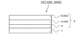
- the intermediate transfer medium 10 of the first invention of the present application will be specifically described below with reference to the drawings.
- the intermediate transfer medium 10 of the first invention is formed on a base material 1 and one surface of the base material 1 (the upper surface of the base material 1 in the case shown in FIG. 1). It is composed of a protective layer 4 and a receiving layer 5.
- the transfer layer 2 including the protective layer 4 and the receiving layer 5 is configured to be transferred to a transfer target during thermal transfer.
- the present invention is not limited to any other requirements as long as this requirement is satisfied, and other layers such as a release layer 3, a release layer, and an adhesive layer can be provided as necessary.
- the present invention is characterized in that the protective layer 4 contains one or more selected from the group consisting of polyvinyl alcohol, polyvinyl butyral, polyvinyl acetal, and polyvinyl pyrrolidone, or a cationic resin.
- the first invention will be described more specifically.
- the substrate 1 is an essential component in the intermediate transfer medium 10 of the present invention, and is provided to hold the protective layer 4.
- the substrate 1 is not particularly limited, and examples thereof include stretched or unstretched films of plastics such as polyethylene terephthalate and polyethylene naphthalate, which have high heat resistance, polypropylene, polycarbonate, cellulose acetate, polyethylene derivatives, polyamide, polymethylpentene, and the like. .
- stacked 2 or more types of these materials can also be used.
- the thickness of the substrate 1 can be appropriately selected depending on the material so that its strength, heat resistance, etc. are appropriate, but usually a thickness of about 1 to 100 ⁇ m is preferably used.
- a transfer layer 2 is formed on a substrate 1 so as to be peelable from the substrate 1 during thermal transfer.
- the transfer layer 2 includes at least a protective layer 4 and a receiving layer 5 which are essential components in the intermediate transfer medium 10 of the present invention.
- the transfer layer 2 is peeled off from the substrate 1 at the time of thermal transfer and transferred to the transfer target.
- an optional release layer 3 for improving the peelability of the transfer layer 2 from the substrate 1 may be provided between the substrate 1 and the protective layer 4.
- the release layer 3 is an arbitrary configuration of the transfer layer 2 and is a layer that is transferred onto the transfer target during thermal transfer.
- the release layer 3 is not particularly limited, and a conventionally known material can be appropriately selected and used.
- cellulose derivatives such as ethyl cellulose, nitrocellulose, and cellulose acetate, acrylic resins such as polymethyl methacrylate, polyethyl methacrylate, and polybutyl acrylate, polyvinyl chloride, vinyl chloride-vinyl acetate copolymer, polyvinyl Thermoplastic resins such as butyral and other vinyl copolymer thermoplastic resins, saturated or unsaturated polyester resins, polyurethane resins, thermally crosslinkable epoxy-amino resins, amino alkyd resins, silicone waxes, silicone resins, silicone modified It can be formed using a resin, a fluororesin, a fluorine-modified resin, polyvinyl alcohol, or the like.
- the release layer 3 preferably contains a filler such as microsilica or polyethylene wax in order to improve the foil breakability. Further, the release layer 3 may be made of one kind of resin, or may be made of two or more kinds of resins. The release layer 3 may be formed using a crosslinking agent such as an isocyanate compound, a catalyst such as a tin catalyst, and an aluminum catalyst in addition to the resin exemplified above.
- a crosslinking agent such as an isocyanate compound, a catalyst such as a tin catalyst, and an aluminum catalyst in addition to the resin exemplified above.
- the release layer 3 is applied and dried on at least a part of the substrate 1 by a known coating method such as roll coating, gravure coating, bar coating or the like by dispersing or dissolving the above resin in a solvent. Can be formed.
- the thickness of the release layer 3 is usually about 0.1 ⁇ m to 5 ⁇ m, preferably about 0.5 ⁇ m to 2 ⁇ m.
- the protective layer 4 is provided for imparting plasticizer resistance to a printed material formed by transferring the transfer layer 2 onto a transfer target.
- the substance contained in the protective layer 4 is (1) a substance that repels a plasticizer component; Substances whose agent components are difficult to reach the image were selected.
- the protective layer 4 imparts plasticizer resistance to the protective layer 4 by repelling the plasticizer component, and according to the substance (2) As a result, the plasticizer component hardly reaches the image, and as a result, the protective layer 4 is imparted with plasticizer resistance.
- one or more kinds selected from the group consisting of polyvinyl alcohol, polyvinyl butyral, polyvinyl acetal, and polyvinyl pyrrolidone are defined as the substance that repels the plasticizer of (1).
- the presence of the substance that repels the plasticizer (1) contained in the protective layer 4 imparts plasticizer resistance to the protective layer 4. 4 plasticizer resistance can be improved. Thereby, even when the protective layer 4 is in contact with a plasticizer resin, for example, vinyl chloride-vinyl acetate copolymer, the plasticizer component can be transferred to the image formed in the receiving layer. Absent.
- a plasticizer resin for example, vinyl chloride-vinyl acetate copolymer
- a specific mechanism for improving the plasticizer resistance of the protective layer 4 by containing one or more selected from polyvinyl alcohol, polyvinyl butyral, polyvinyl acetal, and polyvinyl pyrrolidone, which are the substances of (1) Is not necessarily clear about.
- polyvinyl alcohol, polyvinyl butyral, and polyvinyl acetal have a hydroxyl group in the structure, and it is considered that the plasticizer resistance is improved by repelling the plasticizer component.
- Polyvinylpyrrolidone has a characteristic that the oxygen group present in the heterocyclic ring repels the plasticizer component in the same way as the hydroxyl group, or is bonded to the oxygen group and a hydrogen group present in the vicinity of the oxygen group. It is presumed that the plasticizer resistance is improved by forming a simple structure.
- polyvinyl alcohol, polyvinyl butyral, and polyvinyl acetal preferably have a saponification degree of 30 to 100%, and more preferably 60 to 100%.
- the protective layer 4 contains polyvinyl alcohol, polyvinyl butyral, or polyvinyl acetal having a saponification degree within this range, the plasticizer resistance can be further improved.
- the saponification degree in this invention means the value which divided the number of moles of the vinyl alcohol structure in a polymer by the number of moles of all the monomers in a polymer.
- one kind or a mixture of two or more kinds selected from polyvinyl alcohol, polyvinyl butyral, polyvinyl acetal, and polyvinyl pyrrolidone, which are the substances of the above (1), is a mass of these one kind (in the case of two or more kinds).
- the weight of the mixture is preferably 20 to 100% of the total weight of the protective layer 4.
- a cationic resin is defined as a substance in which the (2) plasticizer component hardly reaches the image.
- the cationic resin of the present invention is a resin having a cationic property.
- a cationic urethane emulsion or the like can be used.
- the specific mechanism of forming the protective layer 4 in which the plasticizer component is difficult to reach the image by containing the cationic resin as the substance (2) is not necessarily clear.
- an attractive force is generated between the cation part of the cationic resin and the conjugated electrons of the plasticizer component, and the plasticizer component is received by the electrical attraction between the cationic resin and the plasticizer component.
- the cationic resin is preferably contained within a range of 20 to 100% with respect to the total mass of the protective layer 4.
- the substance (1) and the substance (2) may be used in combination.
- the protective layer 4 may contain one or a mixture of two or more selected from polyvinyl alcohol, polyvinyl butyral, polyvinyl acetal, and polyvinyl pyrrolidone, and a cationic resin.
- the plasticizer resistance can be improved more effectively by using a combination of a substance that repels the plasticizer component and a substance that binds to the plasticizer component.
- the total mass of the substance (1) and the substance (2) is preferably contained within a range of 20 to 100% with respect to the total mass of the protective layer 4.
- a protective layer coating solution is prepared by dissolving or dispersing one or more selected from the group consisting of the substance (1) above, or the substance (2) above with an appropriate solvent. Then, when this is applied and dried on the release layer 3 to form a protective coating film, the coating film is not cracked. Thereby, it can be set as the protective layer 4 with high coating-film stability.
- the protective layer 4 for example, a lubricant, a plasticizer, a filler, an antistatic agent, an antiblocking agent, a crosslinking agent, an antioxidant, an ultraviolet absorber, a light stabilizer, a dye, a pigment, etc. Coloring agents, fluorescent brighteners, other additives, and the like may be added.
- the protective layer 4 may be formed by dissolving or dispersing one or more selected from polyvinyl alcohol, polyvinyl butyral, polyvinyl acetal, and polyvinyl pyrrolidone, or a cationic resin in a suitable solvent.
- the coating liquid is prepared on a substrate 1 or a release layer 3 provided as necessary by a conventionally known means such as a gravure printing method, a screen printing method or a reverse coating method using a gravure plate. It can be formed by coating and drying.
- the thickness of the protective layer 4 is not particularly limited, but is usually 0.1 to 50 ⁇ m, preferably about 1 to 20 ⁇ m, after drying.
- the protective layer coating solution is formed by dispersing or dissolving one or more selected from the above-mentioned polyvinyl alcohol, polyvinyl butyral, polyvinyl acetal, and polyvinyl pyrrolidone, or a cationic resin in an aqueous solvent.
- the aqueous coating liquid is preferable in that a protective layer can be formed without deteriorating the properties of other layers.
- a receiving layer 5 constituting the transfer layer 2 is provided on the protective layer 4.
- an image is formed by thermal transfer from a thermal transfer sheet having a color material layer by thermal transfer.
- the transfer layer 2 of the intermediate transfer medium on which the image is formed is transferred onto the transfer target, and as a result, a printed matter is formed.
- a material for forming the receiving layer 5 a conventionally known resin material that can easily receive a heat transferable color material such as a sublimation dye or a heat-meltable ink can be used.
- polyolefin resin such as polypropylene, halogenated resin such as polyvinyl chloride or polyvinylidene chloride, polyvinyl acetate, vinyl chloride-vinyl acetate copolymer, ethylene-vinyl acetate copolymer or polyacrylate Vinyl resins, polyester resins such as polyethylene terephthalate or polybutylene terephthalate, polystyrene resins, polyamide resins, copolymers of olefins such as ethylene or propylene and other vinyl polymers, cellulose resins such as ionomers or cellulose diastases Polycarbonate, etc., and vinyl chloride resin, acrylic-styrene resin or polyester resin is particularly preferable.
- halogenated resin such as polyvinyl chloride or polyvinylidene chloride
- polyvinyl acetate vinyl chloride-vinyl acetate copolymer
- the receiving layer 50 constituting the intermediate transfer medium of the third invention can be used as it is. Details of the receiving layer 50 will be described later.
- the adhesiveness of the receiving layer 5 itself is not necessarily required.
- the receptor layer 5 may be formed using an adhesive resin material such as vinyl chloride-vinyl acetate copolymer. preferable.
- the receptive layer 5 is a receptive layer coating obtained by adding one or more materials selected from the above-mentioned materials and various additives as necessary, and dissolving or dispersing them in an appropriate solvent such as water or an organic solvent.
- a working solution is prepared, and this can be applied and dried by means of a gravure printing method, a screen printing method or a reverse coating method using a gravure plate. Its thickness is about 1 ⁇ m to 10 ⁇ m in a dry state.
- the transfer layer 2 on which the above-described thermal transfer image of the intermediate transfer medium is formed is transferred onto the transfer target, and as a result, a printed matter having a thermal transfer image having various durability is obtained.
- the transfer target to which the intermediate transfer medium of the present invention is applied is not particularly limited.
- vinyl chloride-vinyl acetate copolymer, polyethylene terephthalate (PET), polycarbonate, natural fiber paper, coated paper, tracing paper, glass Any of metal, ceramics, wood, cloth and the like may be used.
- the intermediate transfer medium 100 of the second invention of the present application has the same configuration as that of the first invention, that is, the base material 1 and one surface of the base material 1 (the base material in the case shown in FIG. 1). 1 and the receiving layer 5.
- the transfer layer 2 having the protective layer 40 and the receiving layer 5 as essential components is transferred to a transfer medium during thermal transfer.
- the intermediate transfer medium 100 of the second invention instead of the protective layer 4 described in the first invention, (i) high polymerization having a number average molecular weight (Mn) of 12000 or more and Tg of 60 ° C. or more. It is characterized by comprising a protective layer 40 mainly containing one kind or a mixture of two or more kinds selected from the group of polyester, (ii) polycarbonate, and (iii) polyester urethane.
- Mn is a number average molecular weight in terms of polystyrene measured by GPC.
- the protective layer 40 constituting the transfer layer 2 has one or more types selected from the group consisting of a polyester having a number-average molecular weight (Mn) of 12,000 or more and a high polymerization degree polyester having a Tg of 60 ° C. or more, polycarbonate, and polyester urethane. As a main component. Thereby, extremely excellent durability is imparted to the protective layer 40. In addition, when the number average molecular weight (Mn) is less than 12000 or a high polymerization degree polyester having a Tg of less than 60 ° C. is used, the durability is remarkably lowered. Further, the polyester urethane in the present invention means a copolymer of polyester and polyurethane.
- high-polymerization polyester having a number average molecular weight (Mn) of 12000 or more and Tg of 60 ° C. or more is less likely to cause tailing during transfer. Therefore, in a field where it is necessary to prevent the occurrence of tailing, a high degree of polymerization polyester can be suitably used as the main body of the protective layer 40.
- polycarbonate, and polyester urethane is contained, It is preferable that a high-polymerization degree polyester having an average molecular weight (Mn) of 12000 or more and a Tg of 60 ° C. or more is contained in a proportion of 50% by mass or more.
- Mn average molecular weight
- Tg melting point
- the number average molecular weight (Mn) contained in the protective layer 40 is 12000 or more, 1 type selected from the group of high polymerization degree polyester, polycarbonate, and polyester urethane whose Tg is 60 degreeC or more, or 2 or more types of mixtures. May be contained as a main component, and the content of the one kind or a mixture of two or more kinds is not particularly limited, but is contained in a proportion of 50% by mass or more with respect to the total mass of the protective layer 40. It is necessary, and it is preferably contained within a range of 50% by mass or more and 100% by mass or less.
- the thickness of the protective layer 40 is not particularly limited. However, when the thickness of the protective layer 40 is less than 2 ⁇ m, the durability tends to decrease. On the other hand, when the thickness of the protective layer 40 is greater than 15 ⁇ m. The foil breakability of the protective layer 40 is reduced, and tailing or the like may occur when the transfer layer is thermally transferred to the transfer target. Considering such points, the thickness of the protective layer 40 is preferably 2 ⁇ m or more and 15 ⁇ m or less.
- the protective layer 40 may contain other materials such as a fluorescent whitening agent and a UV absorber for improving weather resistance.
- the protective layer 40 As a method for forming the protective layer 40, one or a mixture of two or more selected from the group of high-polymerized polyester, polycarbonate, and polyester urethane having a number average molecular weight (Mn) of 12000 or more and a Tg of 60 ° C. or more. Is dissolved or dispersed in a suitable solvent to prepare a protective layer coating solution, and this is applied to the substrate 1 or, if necessary, the release layer 3 provided on the substrate 1 by a gravure printing method, It can be formed by applying and drying by a conventionally known means such as a screen printing method or a reverse coating method using a gravure plate.
- Mn number average molecular weight
- the release layer 3 can be formed between the substrate 1 and the protective layer 40 as in the first invention.
- the high polymerization degree polyester with a number average molecular weight (Mn) of 12000 or more and Tg of 60 ° C. or more has high adhesion to the base material 1, when the high polymerization degree polyester is adopted as the main component of the protective layer 40. It is preferable to form the release layer 3 between the substrate 1 and the protective layer 40.
- the transfer layer 2 can be easily peeled off from the base material even if it does not have the release layer 3. can do.
- the release layer 3 described in the first invention can be used as it is, and the description thereof is omitted here.
- the base material 1 and the receiving layer 5 described in the first invention can be used as they are.
- the receiving layer 50 constituting the intermediate transfer medium of the third invention can be used as it is. Details of the receiving layer 50 will be described later.
- the intermediate transfer medium 200 of the third invention of the present application has the same configuration as that of the first and second inventions, that is, the base material 1 and one surface of the base material 1 (in the case shown in FIG. 1).
- the protective layer 4 or 40 and the receiving layer 50 are formed on the upper surface of the substrate 1.
- the third invention is characterized in that the receiving layer 50 contains the side chain type aralkyl-modified silicone in a ratio of 0.5 to 5 mass% with respect to the total mass of the receiving layer 50.
- the third invention will be described more specifically.
- a transfer layer 2 is formed on a substrate 1 so as to be peelable from the substrate 1 during thermal transfer.
- the transfer layer 2 is composed of at least the protective layers 4 and 40 that are essential components of the intermediate transfer medium 200 of the present invention, or a conventionally known protective layer and a receiving layer 50 (in the case shown in FIG. 1). In this case, it is composed of a release layer 3, a protective layer 4, and a receiving layer 50).
- the transfer layer 2 is peeled off from the substrate 1 during thermal transfer and transferred to a transfer target.
- the release layer 3 may be formed between the substrate 1 and the protective layer. Good.
- the release layer 3 described in the first invention can be used as it is, and description thereof is omitted here. The same applies to the substrate 1.
- the protective layer 4 is an essential component in the intermediate transfer medium of the third invention.
- the protective layer 4 described in the first invention that is, one or more selected from the group consisting of polyvinyl alcohol, polyvinyl butyral, polyvinyl acetal, and polyvinyl pyrrolidone, or a cationic resin
- the protective layer 4 containing may be used as it is.
- the protective layer 40 described in the second invention that is, a high-polymerized polyester, polycarbonate having a number average molecular weight (Mn) of 12000 or more and Tg of 60 ° C. or more, and
- the protective layer 40 mainly containing one or a mixture of two or more selected from the group of polyester urethanes may be used as it is.
- a conventionally known protective layer may be used in place of these protective layers 4 and 40.
- Conventionally known protective layers include, for example, polyester resins, acrylic resins, ultraviolet absorbing resins, epoxy resins, polystyrene resins, polyurethane resins, acrylic urethane resins, resins obtained by modifying these resins with silicone, Examples thereof include a mixture, an ionizing radiation curable resin, and an ultraviolet absorbing resin.
- the protective layer containing the ionizing radiation curable resin can be suitably used as a binder for the protective layer because it is particularly excellent in plasticizer resistance and scratch resistance.
- the ionizing radiation curable resin is not particularly limited and can be appropriately selected from conventionally known ionizing radiation curable resins.
- a radical polymerizable polymer or oligomer can be crosslinked by irradiation with ionizing radiation. Cured, added with a photopolymerization initiator as required, and polymerized and cross-linked with an electron beam or ultraviolet light can be used.
- a protective layer containing an ultraviolet absorbing resin is excellent in imparting light resistance to a printed material.
- the ultraviolet absorbing resin for example, a resin obtained by reacting and bonding a reactive ultraviolet absorber to a thermoplastic resin or the above ionizing radiation curable resin can be used. More specifically, addition-polymerizable double-reactive organic UV absorbers such as salicylates, benzophenones, benzotriazoles, substituted acrylonitriles, nickel chelates, hindered amines, etc. Examples thereof include a bond (for example, a vinyl group, an acryloyl group, a methacryloyl group, etc.), an alcoholic hydroxyl group, an amino group, a carboxyl group, an epoxy group, and a reactive group such as an isocyanate group.
- a bond for example, a vinyl group, an acryloyl group, a methacryloyl group, etc.
- an alcoholic hydroxyl group an amino group
- a carboxyl group an epoxy group
- a reactive group such as an isocyanate group.
- colorants such as lubricants, plasticizers, fillers, antistatic agents, antiblocking agents, crosslinking agents, antioxidants, ultraviolet absorbers, light stabilizers, dyes, pigments, etc. Additives and the like may be added.
- a method for forming the protective layer the method described in the protective layer 4 in the first invention, the protective layer 40 in the second invention, or one or more of the resin materials exemplified above is appropriately used.
- a protective layer coating solution is prepared by dissolving or dispersing in a solvent, and this is applied to the substrate 1 and, if necessary, the release layer 3 provided on the substrate 1 by a gravure printing method, screen printing method or It can be formed by applying and drying by a conventionally known means such as a reverse coating method using a gravure plate.
- the thickness of the protective layer is not particularly limited, but is usually from 0.1 to 50 ⁇ m, preferably from about 1 to 20 ⁇ m, after drying.
- a receiving layer 50 constituting the transfer layer 2 is provided on the protective layer.
- an image is formed by a thermal transfer method from a thermal transfer sheet having a color material layer.
- the transfer layer 2 of the intermediate transfer medium on which the image is formed is transferred onto the transfer target, and as a result, a printed matter is formed.
- the adhesiveness to the transfer target hereinafter sometimes referred to as adhesiveness
- heat transferability such as sublimation dyes or heat-meltable inks is used. It is possible to use a resin material that easily accepts the dye.
- the resin material contained in the receiving layer 50 is not particularly limited, but in the present invention, for example, polyolefin resin such as polypropylene, vinyl chloride-vinyl acetate copolymer, ethylene-vinyl acetate copolymer, polyvinylidene chloride, etc.
- Polyester resins such as halogenated polymers, polyvinyl acetate and polyacrylic esters, polystyrene resins, polyamide resins, copolymers of olefins such as ethylene and propylene and other vinyl monomers, ionomers, cellulose diacetates, etc.
- Cellulosic resins, polycarbonate resins and the like can be mentioned. Particularly preferred among these resin materials can include polyester resins, vinyl chloride-vinyl acetate copolymers, mixtures thereof, and the like.
- the receiving layer 50 contains a side chain aralkyl-modified silicone.
- the side chain aralkyl-modified silicone plays a role as a release agent and has excellent release properties. Therefore, according to the present invention in which the receiving layer contains the side chain type aralkyl-modified silicone, it is possible to prevent the thermal transfer sheet having the color material layer and the receiving layer 50 of the intermediate transfer medium from being fused at the time of image formation.
- the side chain type aralkyl-modified silicone contained in the receiving layer 50 of the present invention is 0.5% by mass or more based on the total mass of the receiving layer 50, that is, the total mass of the total mass of the resin material and the release agent. If it is contained, it has excellent releasability.
- the content of the release agent contained in the receiving layer 50 can be greatly reduced as compared with the conventional one, and the temperature at which the transferred object is not deformed. For example, at a temperature of about 155 ° C., the transfer layer 2 including the receiving layer 50 can be transferred to the transfer target.
- the receiving layer 50 of the present invention contains the side chain aralkyl-modified silicone in a proportion of 0.5% by mass or more and 5% by mass or less with respect to the total mass of the receiving layer 50.
- the side-chain aralkyl-modified silicone described above is excellent in releasability, when attention is paid to further improving the releasability of the receiving layer 50, the receiving layer 50 has side chains serving as a releasing agent. It is preferable that a type epoxy-modified silicone is further contained. Although the side chain type epoxy-modified silicone is inferior to the side chain type aralkyl-modified silicone in terms of adhesion, the side-chain type epoxy-modified silicone has an excellent release property compared to the side chain type aralkyl-modified silicone.
- the side chain type epoxy-modified silicone is preferably contained at a ratio of 0.5 to 5% by mass with respect to the total mass of the receiving layer.
- the content of the side chain type epoxy-modified silicone is less than 0.5% by mass, the effect of improving the releasability by containing the side chain type epoxy-modified silicone is reduced, and the side chain type epoxy modification is also performed. This is because when the content of silicone is 5% by mass or more, the content of the separation-type agent increases and the adhesiveness may be lowered.
- the receiving layer 50 contains the side chain type aralkyl-modified silicone and the side chain type epoxy-modified silicone
- the content is within the range described above, and the sum, that is, the side
- the total mass of the chain-type aralkyl-modified silicone and the side-chain-type epoxy-modified silicone is preferably 1 to 5% by mass with respect to the total mass of the receiving layer 50.
- the receiving layer 50 can be provided with particularly excellent releasability and adhesion. .
- the mass ratio of the side chain type epoxy-modified silicone is outside the range of 9: 1 to 1: 9, that is, when the proportion of the side chain type aralkyl modified silicone is large, the side chain type epoxy modified silicone occupies.
- the ratio is large, in the former case, the effect of further improving the releasability cannot be obtained, and in the latter case, the adhesiveness to the transfer medium is lowered.
- the mass ratio of the side chain aralkyl-modified silicone to the side chain epoxy-modified silicone is preferably in the range of 9: 1 to 1: 9.
- the intermediate transfer medium according to the third aspect of the invention has an essential structure that the receiving layer 50 contains aralkyl-modified silicone, and preferably further contains side-chain type epoxy-modified silicone. Although it takes a configuration, this does not mean that a release agent other than the side chain type aralkyl-modified silicone and the side chain type epoxy-modified silicone is not contained. That is, if necessary, the receiving layer 50 can contain a substance serving as a release agent other than the side chain type aralkyl-modified silicone and the side chain type epoxy-modified silicone.
- the receiving layer 50 includes, for example, one or a plurality of resin materials selected from the materials exemplified above, and the side chain type aralkyl-modified silicone described above, and if necessary, the side chain type epoxy-modified silicone, or Add other release agent and dissolve or disperse in water or an appropriate solvent such as organic solvent to prepare a coating solution for the receiving layer, which is then reverse coated using gravure printing, screen printing or gravure printing It can be formed by coating and drying by means such as a method.
- the thickness of the receiving layer 50 is not particularly limited, but is usually about 1 to 10 ⁇ m in a dry state.
- the adhesiveness of the receiving layer 50 itself is not necessarily required.
- the receptor layer 50 may be formed using an adhesive resin material such as vinyl chloride-vinyl acetate copolymer. preferable.
- the primer layer it is preferable to provide the primer layer mentioned later.
- the receiving layer 50 is made of a coating for the receiving layer by adding one or more materials selected from the above-mentioned materials and various additives as necessary, and dissolving or dispersing them in an appropriate solvent such as water or an organic solvent.
- a working solution is prepared, and this can be applied and dried by means of a gravure printing method, a screen printing method or a reverse coating method using a gravure plate.
- a primer layer (not shown) may be formed between the protective layer and the receiving layer 50.
- the primer layer include polyurethane resin, polyester resin, polyamide resin, epoxy resin, phenol resin, polyvinyl chloride resin, polyvinyl acetate resin, vinyl chloride-vinyl acetate copolymer, acid modification Polyolefin resins, copolymers of ethylene and vinyl acetate or acrylic acid, (meth) acrylic resins, polyvinyl alcohol resins, polyvinyl acetal resins, polybutadiene resins, rubber compounds, etc.
- the primer layer preferably contains a filler such as microsilica or polyethylene wax. This primer layer can also be provided between the protective layer and the receiving layer in the first and second inventions as well.
- the transfer layer 2 on which the above-described thermal transfer image of the intermediate transfer medium is formed is transferred onto the transfer target, and as a result, a printed matter having a thermal transfer image having various durability is obtained.
- the transfer target to which the intermediate transfer medium of the present invention is applied is not particularly limited.
- vinyl chloride-vinyl acetate copolymer, polyethylene terephthalate (PET), polycarbonate, natural fiber paper, coated paper, tracing paper, glass Any of metal, ceramics, wood, cloth and the like may be used.
- the intermediate transfer medium of the third invention can transfer the transfer layer to these transferred materials at a temperature of about 155 ° C.
- the transferred material made of a material that does not deform at a temperature of 155 ° C. or lower. It can be used in a particularly preferred combination with the body.
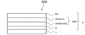
- the intermediate transfer medium 300 of the fourth invention of the present application is an intermediate transfer medium in which a substrate 1, a protective layer 304 having a laminated structure of two or more layers, and a receiving layer 50 are laminated in this order.
- the protective layers 304 having a laminated structure one protective layer 304B is selected from the group of high-polymerization degree polyester, polycarbonate, and polyester urethane having a number average molecular weight (Mn) of 12000 or more and Tg of 60 ° C. or more.
- the other protective layer 304A is selected from the group consisting of polyvinyl alcohol, polyvinyl butyral, polyvinyl acetal, and polyvinyl pyrrolidone. It is a plasticizer-resistant layer containing a seed, two or more kinds, or a cationic resin, and the receiving layer 50 has a side chain type aralkyl-modified silicone, Wherein the total weight of the receiving layer to be contained in a proportion of from 0.5 to 5 mass%.
- Base material As the base material 1 constituting the intermediate transfer medium 300, those described for the intermediate transfer medium of the first invention can be used as they are, and the description thereof is omitted here.
- the protective layer 304 having a laminated structure of two or more layers is provided.
- one protective layer 304B constituting the protective layer 304 having the laminated structure has a number average molecular weight (Mn). 12000 or more, Tg is 60 degreeC or more Highly-polymerized polyester, polycarbonate, and a durable layer mainly comprising one or a mixture selected from the group of polyester urethane, and another protection
- the layer 304A is a plasticizer layer containing one or more selected from the group consisting of polyvinyl alcohol, polyvinyl butyral, polyvinyl acetal, and polyvinyl pyrrolidone, or a cationic resin.
- the plasticizer-resistant layer 304A which is one layer constituting the protective layer 304 having a laminated structure, can use the protective layer 4 described in the intermediate transfer medium 10 of the first invention as a plasticizer-resistant layer as it is. Detailed description will be omitted here.
- the presence of the plasticizer-resistant layer 304A constituting the protective layer 304 can impart excellent plasticizer resistance to the printed material to which the protective layer 304 has been transferred.
- the durability layer 304B which is another layer different from the one layer constituting the protective layer 304 having a laminated structure, is durable against the protection layer 40 described in the intermediate transfer medium 100 of the second invention.
- the layer can be used as it is, and a detailed description thereof is omitted here.
- excellent durability can be imparted to the printed matter to which the protective layer 304 has been transferred by the presence of the durable layer 304B constituting the protective layer 304.
- the protective layer 304 may have a two-layer structure in which a plasticizer-resistant layer 304A and a durable layer 304B are laminated. In addition to the plasticizer-resistant layer 304A and the durable layer 304B, any other layer may be used. The structure of three or more layers containing may be sufficient. In the case of the protective layer 304 having a laminated structure of three or more layers, the plasticizer-resistant layer 304A and the durable layer 304B may be directly laminated, or indirectly via any other layer. It may be laminated.
- One layer constituting the protective layer 304 closest to the substrate 1 may be a plasticizer-resistant layer 304A or a durable layer 304B, which is an arbitrary protective layer. May be.
- the optional protective layer the conventionally known protective layer described in the third invention can be used as it is.
- the positional relationship between the plasticizer-resistant layer 304A and the durable layer 304B is not particularly limited. As shown in FIG. 2, the plasticizer-resistant layer 304A and the durable layer 304B are laminated in this order from the substrate 1 side. 3, the durable layer 304B and the plasticizer-resistant layer 304A may be laminated in this order from the substrate 1 side as shown in FIG. In any case, excellent plasticizer resistance and durability can be imparted to the printed material to which the protective layer 304 having the laminated structure is transferred.
- the plasticizer-resistant layer is formed using an aqueous coating solution as described above. By doing so, it is possible to prevent the resin constituting the plasticizer-resistant layer from penetrating the release layer 3 and reaching the substrate 1. That is, according to the plasticizer-resistant layer formed using the water-based coating liquid, it is possible to prevent the peeling performance from being lowered when the release layer 3 is provided between the substrate 1 and the plasticizer-resistant layer.
- a preferred embodiment is a configuration in which an optional release layer 3, a plasticizer-resistant layer formed by an aqueous coating solution, and a durable layer are laminated in this order on the substrate 1. Can be mentioned.
- release layer 3 between the substrate 1 and the protective layer 304 for improving the peelability of the protective layer 304 during thermal transfer.
- the release layer 3 described in the intermediate transfer medium of the first invention can be used as it is, and detailed description thereof is omitted here.
- the layer closest to the base material 1 is the durable layer 304B, and the durable layer is
- the protective layer 304 can be easily peeled from the substrate 1 without providing the peeling layer 3.
- the release layer 3 may be provided in order to further improve the peelability.
- the receiving layer 50 described in the intermediate transfer medium 200 of the third invention can be used as it is, and detailed description thereof is omitted here.
- the presence of the receiving layer 50 provides the intermediate transfer medium 300 with excellent releasability from the thermal transfer sheet and excellent adhesion to the transfer target.
- Example 1 Using a PET film with a thickness of 12 ⁇ m as a base material, a coating solution for forming a release layer having the following composition was applied to one side of the base material by a bar coater method so as to be 0.8 ⁇ m after drying. Thus, a release layer was formed. Next, a protective layer-forming coating solution 1 having the following composition was applied onto the release layer so as to have a thickness of 1.0 ⁇ m after drying by a bar coater method, thereby forming a protective layer. Next, on this protective layer, a receiving layer forming coating solution 1 having the following composition was applied by drying so as to have a thickness of 2.5 ⁇ m and dried to form a receiving layer. Example 1 An intermediate transfer medium was obtained.
- Example 2 An intermediate transfer medium of Example 2 was obtained in the same manner as Example 1 except that the protective layer forming coating solution 1 was changed to a protective layer forming coating solution 2 having the following composition.
- Example 3 An intermediate transfer medium of Example 3 was obtained in the same manner as in Example 1 except that the protective layer forming coating solution 1 was changed to the protective layer forming coating solution 3 having the following composition.
- ⁇ Protective layer forming coating solution 3> Polyvinyl acetal 50 parts (KX-1 saponification degree: 70.0-90.0% made by Sekisui Chemical Co., Ltd.) ⁇ 25 parts of water ⁇ 25 parts of IPA
- Example 4 An intermediate transfer medium of Example 4 was obtained in the same manner as Example 1 except that the protective layer forming coating solution 1 was changed to a protective layer forming coating solution 4 having the following composition.
- Example 5 An intermediate transfer medium of Example 5 was obtained in the same manner as in Example 1 except that the protective layer forming coating solution 1 was changed to a protective layer forming coating solution 5 having the following composition.
- Example 6 An intermediate transfer medium of Example 6 was obtained in the same manner as in Example 1 except that the protective layer forming coating solution 1 was changed to a protective layer forming coating solution 6 having the following composition.
- Example 7 An intermediate transfer medium of Example 7 was obtained in the same manner as Example 1 except that the protective layer forming coating solution 1 was changed to a protective layer forming coating solution 7 having the following composition.
- Example 8 An intermediate transfer medium of Example 8 was obtained in the same manner as Example 1 except that the protective layer forming coating solution 1 was changed to a protective layer forming coating solution 8 having the following composition.
- Example 9 An intermediate transfer medium of Example 9 was obtained in the same manner as Example 1 except that the protective layer forming coating solution 1 was changed to a protective layer forming coating solution 9 having the following composition.
- Comparative Example 1 An intermediate transfer medium of Comparative Example 1 was obtained in the same manner as in Example 1 except that the protective layer forming coating solution 1 was changed to a protective layer forming coating solution 10 having the following composition.
- Comparative Example 2 An intermediate transfer medium of Comparative Example 2 was obtained in the same manner as Example 1 except that the protective layer forming coating solution 1 was changed to a protective layer forming coating solution 11 having the following composition.
- Plasticizer resistance evaluation >> Vinyl chloride sheet Altron (registered trademark) # 430 (Mitsubishi Resin Co., Ltd.) was cut out to 5 cm ⁇ 5 cm, superimposed on the prints of Examples 1 to 9 and Comparative Examples 1 and 2, and a load of 1750 g was applied at 82 ° C. After the storage, the vinyl chloride sheet was peeled off from the prints of Examples 1 to 9 and Comparative Examples 1 and 2, and the image of the prints was transferred to the vinyl chloride sheet. The plasticizer resistance was evaluated according to the following evaluation criteria. The evaluation results are shown in Table 1. ⁇ Evaluation criteria> ⁇ : No transition to vinyl chloride sheet ⁇ : Thin transition to vinyl chloride sheet, but the printed image is not faded ⁇ : Substantially shifted to the vinyl chloride sheet, the printed image is also Faded
- Example 8 containing resin has the plasticizer resistance outstanding compared with the comparative examples 1 and 2 which do not contain these substances. It can also be seen that Examples 1 to 9 are all excellent in coating film stability.
- Example 10 A polyethylene terephthalate film (Lumirror, manufactured by Toray Industries, Inc.) having a thickness of 12 ⁇ m is used as a substrate, and a coating solution for forming a release layer having the above composition is applied on the substrate so as to have a thickness of 1.0 ⁇ m in a dry state. And a release layer was formed. Next, a protective layer-forming coating solution 12 having the following composition was applied on the release layer so as to have a thickness of 10.0 ⁇ m in a dry state to form a protective layer.
- a coating solution for forming a release layer having the above composition is applied on the substrate so as to have a thickness of 1.0 ⁇ m in a dry state.
- a release layer was formed.
- a protective layer-forming coating solution 12 having the following composition was applied on the release layer so as to have a thickness of 10.0 ⁇ m in a dry state to form a protective layer.
- the receiving layer-forming coating solution 1 having the above composition was applied on the protective layer so as to have a thickness of 2.0 ⁇ m in a dry state to form a receiving layer to obtain an intermediate transfer medium of Example 10. It was.
- the release layer forming coating solution, the protective layer forming coating solution 12 and the receiving layer forming coating solution 1 were all applied by gravure coating.
- Example 11 An intermediate transfer medium of Example 11 was obtained in the same manner as Example 10 except that the protective layer forming coating solution 12 was changed to a protective layer forming coating solution 13 having the following composition.
- Example 12 An intermediate transfer medium of Example 12 was obtained in the same manner as Example 10 except that the protective layer forming coating solution 12 was changed to a protective layer forming coating solution 14 having the following composition.
- Example 13 An intermediate transfer medium of Example 13 was obtained in the same manner as Example 10 except that the protective layer forming coating solution 12 was changed to a protective layer forming coating solution 15 having the following composition.
- Example 14 An intermediate transfer medium of Example 14 was obtained in the same manner as Example 10 except that the protective layer forming coating solution 12 was changed to a protective layer forming coating solution 16 having the following composition.
- Example 15 An intermediate transfer medium of Example 15 was obtained in the same manner as Example 10 except that the protective layer forming coating solution 12 was changed to a protective layer forming coating solution 17 having the following composition.
- Polyester urethane resin 30.3 parts (UR-1350, 33% solution, manufactured by Toyobo Co., Ltd.)
- Toluene 29.9 parts ⁇ MEK 29.8 parts
- Example 16 An intermediate transfer medium of Example 16 was obtained in the same manner as in Example 10 except that the protective layer-forming coating solution 12 was applied to a thickness of 5.0 ⁇ m in a dry state to form a protective layer. It was.
- Example 17 An intermediate transfer medium of Example 17 was obtained in the same manner as Example 10 except that the protective layer-forming coating solution 14 was applied to a thickness of 2.5 ⁇ m in a dry state to form a protective layer. .
- Example 18 On a 12 ⁇ m thick polyethylene terephthalate film (Lumirror, manufactured by Toray Industries, Inc.), the protective layer forming coating solution 14 is applied to a thickness of 2.5 ⁇ m in a dry state as a release layer and a protective layer. Further, the receptor layer-forming coating solution 1 having the above composition was applied on the release layer / protective layer to a thickness of 2.0 ⁇ m in a dry state to form a receptor layer. A transfer medium was obtained. The release layer / protective layer forming coating solution 14 and the receiving layer forming coating solution 1 were all applied by gravure coating.
- the protective layer forming coating solution 14 On a 12 ⁇ m thick polyethylene terephthalate film (Lumirror, manufactured by Toray Industries, Inc.), the protective layer forming coating solution 14 is applied to a thickness of 2.5 ⁇ m in a dry state as a release layer and a protective layer. Further, the receptor layer-forming coating solution 1 having the above composition was applied on the release layer / protective layer to a thickness
- Comparative Example 3 An intermediate transfer medium of Comparative Example 3 was obtained in the same manner as Example 10 except that the protective layer forming coating solution 12 was changed to a protective layer forming coating solution 18 having the following composition.
- Comparative Example 4 An intermediate transfer medium of Comparative Example 4 was obtained in the same manner as Example 10 except that the protective layer forming coating solution 12 was changed to a protective layer forming coating solution 19 having the following composition.
- ⁇ Durability test (Taber test) >> Using an HDP-600 printer (manufactured by HID), the intermediate transfer media of Examples 10 to 18 and Comparative Examples 3 and 4 were superimposed on a vinyl chloride card (manufactured by DNP), and a transfer layer (peeling layer, protective layer, The receiving layer was transferred to form prints of Examples 10 to 18 and Comparative Examples 3 and 4.
- a wear wheel CS-10F was used for this printed matter, and the wear wheel was polished every 250 times with a load of 500 gf, and a total of 1500 times was polished. The surface condition was visually observed after polishing, and an evaluation test was performed according to the following evaluation criteria. The evaluation test results are shown in Table 2.
- the printed material (image) is not scraped at all.
- ⁇ The printed material (image) is hardly scraped.
- X The printed material (image) is considerably shaved.
- Tailing (foil breakability) test >> The tailings (foil breakability) of the printed materials of Examples 10 to 18 and Comparative Examples 3 and 4 were visually confirmed, and an evaluation test was performed according to the following evaluation criteria. The evaluation test results are shown in Table 2. ⁇ Evaluation criteria> ⁇ ⁇ ⁇ ⁇ No tailing (1mm or less) ⁇ ... Tailing hardly occurs (2mm or less) ⁇ ⁇ ⁇ ⁇ Slight tailing (about 5mm) ⁇ ⁇ ⁇ ⁇ Tailing occurs considerably (more than 10mm)
- the protective layer has one or two selected from the group of high-polymerization degree polyester, polycarbonate, and polyester urethane having a number average molecular weight (Mn) of 12000 or more and Tg of 60 ° C. or more.
- Mn number average molecular weight
- the intermediate transfer media of Examples 10 to 18 containing the above mixture as a main component are all excellent in durability.
- Comparative Example 3 using an acrylic resin and Comparative Example 4 using a polyester having a number average molecular weight (Mn) of less than 12000 and a Tg of less than 60 ° C. are inferior in durability.
- examples in which the protective layer contains a high-polymerization degree polyester having a number average molecular weight (Mn) of 12000 or more and a Tg of 60 ° C. or more have no or little occurrence of tailing, In particular, it can be seen that good evaluation could be obtained.
- a release layer forming coating solution having the above composition is applied to one surface of the base material by a gravure coating method so as to be 1.0 ⁇ m after drying.
- a release layer was formed.
- a protective layer-forming coating solution 20 having the following composition was applied onto the release layer by a gravure coating method so as to have a thickness of 2.0 ⁇ m after drying, thereby forming a protective layer.
- a primer layer-forming coating solution having the following composition was applied onto the protective layer by a gravure coating method so as to have a thickness of 1.0 ⁇ m after drying, thereby forming a primer layer.
- the receiving layer-forming coating solution 2 having the following composition was applied by drying so as to have a thickness of 2.5 ⁇ m and dried to form a receiving layer.
- a transfer medium was obtained.
- Example 20 An intermediate transfer medium of Example 20 was obtained in the same manner as Example 19 except that the receiving layer forming coating solution 2 was changed to the receiving layer forming coating solution 3 having the following composition.
- Example 21 An intermediate transfer medium of Example 21 was obtained in the same manner as in Example 19 except that the receiving layer forming coating solution 2 was changed to the receiving layer forming coating solution 4 having the following composition.
- Example 22 An intermediate transfer medium of Example 22 was obtained in the same manner as in Example 19 except that the receiving layer forming coating solution 2 was changed to the receiving layer forming coating solution 5 having the following composition.
- Example 23 An intermediate transfer medium of Example 23 was obtained in the same manner as Example 19 except that the receiving layer forming coating solution 2 was changed to the receiving layer forming coating solution 6 having the following composition.
- Example 24 An intermediate transfer medium of Example 24 was obtained in the same manner as in Example 19 except that the receiving layer forming coating solution 2 was changed to the receiving layer forming coating solution 7 having the following composition.
- Example 25 An intermediate transfer medium of Example 25 was obtained in the same manner as Example 19 except that the receiving layer forming coating solution 2 was changed to the receiving layer forming coating solution 8 having the following composition.
- Comparative Example 5 An intermediate transfer medium of Comparative Example 5 was obtained in the same manner as in Example 19 except that the receiving layer forming coating solution 2 was changed to a receiving layer forming coating solution 9 having the following composition.
- Comparative Example 6 An intermediate transfer medium of Comparative Example 6 was obtained in the same manner as in Example 19 except that the receiving layer forming coating solution 2 was changed to the receiving layer forming coating solution 10 having the following composition.
- Comparative Example 7 An intermediate transfer medium of Comparative Example 7 was obtained in the same manner as in Example 19 except that the receiving layer forming coating solution 2 was changed to the receiving layer forming coating solution 11 having the following composition.
- Comparative Example 8 An intermediate transfer medium of Comparative Example 8 was obtained in the same manner as in Example 19 except that the receiving layer forming coating solution 2 was changed to a receiving layer forming coating solution 12 having the following composition.
- the card used is a vinyl chloride card (DNP) having the following composition.
- ⁇ Dye releasability evaluation >> Check the dye ribbon after printing a solid black on the receiving layer of the intermediate transfer media of Examples 19 to 25 and Comparative Examples 5 to 8, and check whether the receiving layer is taken on the dye layer side and the image is not defective. Evaluation was performed according to the following criteria. The evaluation results are shown in Table 3. ⁇ Evaluation criteria> ⁇ ⁇ ⁇ ⁇ No damage to the dye layer and no defects in the prints. ⁇ : The receiving layer is slightly damaged, but the printed material is not defective. ⁇ : The dye layer is considerably damaged, and the printed matter is slightly defective. ⁇ : The dye layer is considerably damaged, and the printed matter is considerably defective.
- Example 26 Using a PET film having a thickness of 12 ⁇ m as a base material, a coating solution for forming a release layer having the above composition is applied to one surface of the base material by a bar coater method so that the thickness becomes 0.8 ⁇ m after drying. Thus, a release layer was formed. Next, the protective layer-forming coating solution 6 having the above composition was applied onto the release layer so as to have a thickness of 1.0 ⁇ m after drying by a bar coater method, and dried to form a first protective layer. Next, a protective layer forming coating solution 12 having the above composition was applied onto the first protective layer by a bar coater method so as to have a thickness of 10.0 ⁇ m after drying, and dried to form a second protective layer. Next, on the second protective layer, the receiving layer forming coating solution 6 having the above composition was applied by drying so as to have a thickness of 2.5 ⁇ m and dried to form a receiving layer. The intermediate transfer medium of Example 26 was obtained.
- Example 27 The intermediate transfer medium of Example 27 is the same as Example 26 except that the protective layer forming coating solution 6 is changed to the protective layer forming coating solution 9 having the above composition when forming the first protective layer. Got.
- Example 28 In forming the first protective layer, the protective layer-forming coating solution 6 is changed to a protective layer-forming coating solution 9 having the above composition, and in forming the second protective layer, the protective layer-forming coating solution is formed.
- An intermediate transfer medium of Example 28 was obtained in the same manner as in Example 26 except that the liquid 12 was changed to the protective layer-forming coating liquid 14 having the above composition.
- Example 29 In forming the first protective layer, the protective layer-forming coating solution 6 is changed to a protective layer-forming coating solution 9 having the above composition, and in forming the second protective layer, the protective layer-forming coating solution is formed.
- An intermediate transfer medium of Example 29 was obtained in the same manner as in Example 26 except that the liquid 12 was changed to the protective layer-forming coating liquid 16 having the above composition.
- Example 30 On a 12 ⁇ m thick polyethylene terephthalate film (Lumirror, manufactured by Toray Industries, Inc.), the protective layer forming coating solution 14 is applied to a thickness of 2.5 ⁇ m in a dry state as a release layer and a protective layer. A release layer / protective layer was formed. Next, the protective layer-forming coating solution 9 having the above composition was applied on the release layer / protective layer to a thickness of 1.0 ⁇ m in a dry state to form a protective layer. Subsequently, the receiving layer-forming coating solution 6 having the above composition was applied on the protective layer so as to have a thickness of 2.0 ⁇ m in a dry state to form a receiving layer, whereby an intermediate transfer medium of Example 30 was obtained. . The release layer / protective layer forming coating solution 14, the protective layer forming coating solution 9, and the receiving layer forming coating solution 6 were all applied by gravure coating.
- Example 31 In forming the first protective layer, the protective layer forming coating solution 6 is changed to the protective layer forming coating solution 12 having the above composition, and in forming the second protective layer, the protective layer forming coating solution is formed.
- An intermediate transfer medium of Example 31 was obtained in the same manner as in Example 26 except that the liquid 12 was changed to the protective layer-forming coating liquid 9 having the above composition.
- Comparative Example 9 In forming the first protective layer, the protective layer forming coating solution 6 is changed to the protective layer forming coating solution 11 having the above composition, and in forming the second protective layer, the protective layer forming coating solution is formed. All the examples except that the liquid 12 was changed to the protective layer-forming coating liquid 18 having the above composition and the receiving layer-forming coating liquid 6 having the above composition was changed to the receiving layer-forming coating liquid 11 having the above composition. In the same manner as in No. 26, an intermediate transfer medium of Comparative Example 9 was obtained.
Abstract
Description
以下に、本願の第1の発明の中間転写媒体10について図面を用いて具体的に説明する。図1に示すように第1の発明の中間転写媒体10は、基材1と、該基材1の一方の面(図1に示す場合にあっては基材1の上面)に形成される保護層4、及び受容層5とから構成される。また、保護層4と受容層5を含む転写層2は熱転写時に被転写体に転写される構成をとる。本発明はこの要件を具備すれば、他の要件についていかなる限定もされることはなく、必要に応じて剥離層3、離型層、接着層等の他の層を設けることができる。 (First invention)
The intermediate transfer medium 10 of the first invention of the present application will be specifically described below with reference to the drawings. As shown in FIG. 1, the intermediate transfer medium 10 of the first invention is formed on a
基材1は本発明の中間転写媒体10における必須の構成であり、保護層4を保持するために設けられる。基材1について特に限定はなく、ポリエチレンテレフタレート、ポリエチレンナフタレート等の耐熱性の高いポリエステル、ポリプロピレン、ポリカーボネート、酢酸セルロース、ポリエチレン誘導体、ポリアミド、ポリメチルペンテン等のプラスチックの延伸または未延伸フィルムが挙げられる。また、これらの材料を2種以上積層した複合フィルムも使用することができる。基材1の厚さは、その強度および耐熱性等が適切になるように材料に応じて適宜選択することができるが、通常は1~100μm程度のものが好ましく用いられる。 (Base material)
The
図1に示すように基材1上には、熱転写時に基材1から剥離可能に設けられた転写層2が形成されている。この転写層2は、少なくとも本発明の中間転写媒体10における必須の構成である保護層4と受容層5とから構成されている。転写層2は熱転写時に基材1から剥離され、被転写体に転写される。 (Transfer layer)
As shown in FIG. 1, a
図示するように基材1からの転写層2の剥離性を向上させるための任意の剥離層3を基材1と保護層4との間に設けてもよい。この剥離層3は、転写層2の任意の構成であり、熱転写時に被転写体上に転写される層である。 (Peeling layer)
As shown in the figure, an
保護層4は、被転写体上へ転写層2を転写することで形成される印画物に、耐可塑剤性を付与するために設けられる。本発明においては、前記機能を奏するための保護層を形成するに際し、以下の点を考慮し、当該保護層4に含有される物質として、(1)可塑剤成分を弾く物質、(2)可塑剤成分が画像に到達しにくい物質を選定した。本発明において選定される(1)の物質によれば、保護層4が、可塑剤成分を弾くことで保護層4に耐可塑剤性が付与される、また、(2)の物質によれば、可塑剤成分が画像に到達しにくいことから、結果的に保護層4に耐可塑剤性が付与される。 (Protective layer of the first invention)
The
図1に示すように、保護層4上には転写層2を構成する受容層5が設けられている。この受容層上には、熱転写によって、色材層を有する熱転写シートから熱転写法によって画像が形成される。そして、画像が形成された中間転写媒体の転写層2は、被転写体上に転写され、その結果、印画物が形成される。このため、受容層5を形成するための材料としては、昇華性染料または熱溶融性インキ等の熱移行性の色材を受容し易い従来公知の樹脂材料を使用することができる。例えば、ポリプロピレン等のポリオレフィン系樹脂、ポリ塩化ビニルもしくはポリ塩化ビニリデン等のハロゲン化樹脂、ポリ酢酸ビニル、塩化ビニル-酢酸ビニル系共重合体、エチレン-酢酸ビニル共重合体もしくはポリアクリル酸エステル等のビニル系樹脂、ポリエチレンテレフタレートもしくはポリブチレンテレフタレート等のポリエステル樹脂、ポリスチレン系樹脂、ポリアミド系樹脂、エチレンもしくはプロピレン等のオレフィンと他のビニルポリマーとの共重合体系樹脂、アイオノマーもしくはセルロースジアスターゼ等のセルロース系樹脂、ポリカーボネート等が挙げられ、特に、塩化ビニル系樹脂、アクリル-スチレン系樹脂またはポリエステル樹脂が好ましい。 (Receptive layer)
As shown in FIG. 1, a
被転写体上には、上述した中間転写媒体の熱転写画像の形成された転写層2が転写され、その結果、各種耐久性に優れた熱転写画像を有する印画物が得られる。本発明の中間転写媒体が適用される被転写体は特に限定されず、例えば、塩化ビニル-酢酸ビニル共重合体、ポリエチレンテレフタレート(PET)、ポリカーボネート、天然繊維紙、コート紙、トレーシングペーパー、ガラス、金属、セラミックス、木材、布等いずれのものでもよい。 (Transfer)
The
次に、本願の第2の発明の中間転写媒体100について説明する。本願第2の発明の中間転写媒体100は、上記の第1の発明と同様の構成、すなわち、基材1と、該基材1の一方の面(図1に示す場合にあっては基材1の上面)に形成される保護層40、及び受容層5とから構成される。保護層40と受容層5とを必須の構成とする転写層2は熱転写時に被転写体に転写される。 (Second invention)
Next, the intermediate transfer medium 100 of the second invention of the present application will be described. The intermediate transfer medium 100 of the second invention of the present application has the same configuration as that of the first invention, that is, the
転写層2を構成する保護層40は、数平均分子量(Mn)が12000以上、Tgが60℃以上の高重合度ポリエステル、ポリカーボネート、及びポリエステルウレタンの群から選択される1種、又は2種以上の混合物を主体として含有する。これにより保護層40に極めて優れた耐久性を付与している。なお、数平均分子量(Mn)が12000未満、あるいは、Tgが60℃未満の高重合度ポリエステルを使用した場合には、耐久性が著しく低下する。また、本発明におけるポリエステルウレタンとは、ポリエステルとポリウレタンとの共重合体を意味するものである。 (Protective layer of the second invention)
The
また、保護層40には、上記で説明した主体となる成分の他、蛍光増白剤、耐侯性を向上させるためのUV吸収剤等のその他の材料を含有していてもよい。 (Other materials)
In addition to the main components described above, the
基材1からの転写層2の剥離性を向上させるために、上記第1の発明と同様に、基材1と保護層40との間に剥離層3を形成することもできる。なお、数平均分子量(Mn)が12000以上、Tgが60℃以上の高重合度ポリエステルは基材1との密着性が高いことから、保護層40の主体として高重合度ポリエステルを採用した場合には、基材1と保護層40との間に剥離層3を形成することが好ましい。一方、ポリカーボネートは、基材1との離型性に優れることから、保護層40の主体としてポリカーボネートを採用した場合には剥離層3を有していなくとも転写層2を基材から容易に剥離することができる。任意の剥離層3は、上記第1の発明で説明した剥離層3をそのまま使用することができ、ここでの説明は省略する。また、基材1、受容層5についても同様に上記第1の発明で説明した基材1、受容層5をそのまま使用することができる。また、受容層5にかえて第3の発明の中間転写媒体を構成する受容層50をそのまま用いることもできる。受容層50についての詳細は後述する。 (Peeling layer)
In order to improve the peelability of the
次に、本願の第3の発明の中間転写媒体について説明する。本願第3の発明の中間転写媒体200は、上記の第1、及び第2の発明と同様の構成、すなわち、基材1と、該基材1の一方の面(図1に示す場合にあっては基材1の上面)に形成される保護層4、40、及び受容層50とから構成される。 (Third invention)
Next, the intermediate transfer medium according to the third aspect of the present invention will be described. The intermediate transfer medium 200 of the third invention of the present application has the same configuration as that of the first and second inventions, that is, the
図1に示すように基材1上には、熱転写時に基材1から剥離可能に設けられた転写層2が形成されている。この転写層2は、少なくとも本発明の中間転写媒体200における必須の構成である保護層4、40、或いは従来公知の保護層と、受容層50とから構成されている(図1に示す場合にあっては、剥離層3、保護層4、受容層50とから構成されている)。そして、この転写層2は熱転写時に基材1から剥離され、被転写体に転写される。 (Transfer layer)
As shown in FIG. 1, a
上記第1の発明、及び第2の発明と同様に、基材1からの転写層2の剥離性を向上させるために、基材1と保護層との間に剥離層3を形成してもよい。剥離層3は、上記第1の発明で説明した剥離層3をそのまま使用することができ、ここでの説明は省略する。基材1についても同様である。 (Peeling layer)
Similarly to the first invention and the second invention, in order to improve the peelability of the
保護層上には転写層2を構成する受容層50が設けられている。この受容層50上には、色材層を有する熱転写シートから熱転写法によって画像が形成される。そして、画像が形成された中間転写媒体の転写層2は、被転写体上に転写され、その結果、印画物が形成される。このため、受容層50を形成するための材料としては、被転写体との密着性(以下、接着性という場合がある。)が高く、且つ昇華性染料または熱溶融性インキ等の熱移行性の染料を受容し易い樹脂材料を使用することができる。 (Receptive layer)
A receiving
また、保護層と受容層50との接着力を向上させるために、保護層と受容層50との間にプライマー層(図示しない)を形成することとしてもよい。プライマー層としては、例えば、ポリウレタン系樹脂、ポリエステル系樹脂、ポリアミド系樹脂、エポキシ系樹脂、フェノール系樹脂、ポリ塩化ビニル系樹脂、ポリ酢酸ビニル系樹脂、塩化ビニル-酢酸ビニル共重合体、酸変性ポリオレフィン系樹脂、エチレンと酢酸ビニル或いはアクリル酸などとの共重合体、(メタ)アクリル系樹脂、ポリビニルアルコール系樹脂、ポリビニルアセタール樹脂、ポリブタジエン系樹脂、ゴム系化合物などを使用することができ、好ましくは、酸素若しくは窒素を有するもの、若しくはイソシアネート化合物を反応性のもの、例えばアクリル樹脂、ウレタン樹脂、アミド樹脂、エポキシ樹脂、アイオノマー樹脂、ゴム系樹脂等の従来の接着剤として既知のものである。また、プライマー層にはマイクロシリカやポリエチレンワックスなどのフィラーを含有させることが好ましい。このプライマー層は、上記第1の発明、及び第2の発明においても、同様に保護層と受容層との間に設けることもできる。 (Primer layer)
Further, in order to improve the adhesive force between the protective layer and the receiving
被転写体上には、上述した中間転写媒体の熱転写画像の形成された転写層2が転写され、その結果、各種耐久性に優れた熱転写画像を有する印画物が得られる。本発明の中間転写媒体が適用される被転写体は特に限定されず、例えば、塩化ビニル-酢酸ビニル共重合体、ポリエチレンテレフタレート(PET)、ポリカーボネート、天然繊維紙、コート紙、トレーシングペーパー、ガラス、金属、セラミックス、木材、布等いずれのものでもよい。特に第3の発明の中間転写媒体は、155℃程度の温度で、これらの被転写体に転写層を転写可能であることから、155℃以下の温度で変形することがない材料からなる被転写体と特に好適に組合せて用いることができる。 (Transfer)
The
次に、本願の第4の発明の中間転写媒体300について図面を用いて具体的に説明する。図2に示すように第4の発明の中間転写媒体300は、基材1と、2層以上の積層構造の保護層304と、受容層50とがこの順で積層されてなる中間転写媒体であって、積層構造の保護層304のうち、一の保護層304Bが、数平均分子量(Mn)が12000以上、Tgが60℃以上の高重合度ポリエステル、ポリカーボネート、及びポリエステルウレタンの群から選択される1種、又は2種以上の混合物を主体として含有する耐久性層であり、他の一の保護層304Aが、ポリビニルアルコール、ポリビニルブチラール、ポリビニルアセタール、及びポリビニルピロリドンからなる群より選択される1種又は2種以上、又は、カチオン性樹脂を含有する耐可塑剤性層であり、受容層50には、側鎖型アラルキル変性シリコーンが、前記受容層の全質量に対し0.5~5質量%の割合で含有されていることを特徴とする。 (Fourth invention)
Next, the
中間転写媒体300を構成する基材1は、上記第1の発明の中間転写媒体で説明したものをそのまま使用することができ、ここでの説明は省略する。 (Base material)
As the
第4の発明では2層以上の積層構造の保護層304を有しており、一実施形態では、該積層構造の保護層304を構成する一の保護層304Bが、数平均分子量(Mn)が12000以上、Tgが60℃以上の高重合度ポリエステル、ポリカーボネート、及びポリエステルウレタンの群から選択される1種、又は2種以上の混合物を主体として含有する耐久性層であり、他の一の保護層304Aが、ポリビニルアルコール、ポリビニルブチラール、ポリビニルアセタール、及びポリビニルピロリドンからなる群より選択される1種又は2種以上、又は、カチオン性樹脂を含有する可塑剤性層となっている。 (Protective layer)
In the fourth invention, the
積層構造の保護層304を構成する一の層である耐可塑剤性層304Aは、上記第1の発明の中間転写媒体10において説明した保護層4を耐可塑剤性層としてそのまま用いることができ、ここでの詳細な説明は省略する。第4の発明では、保護層304を構成する耐可塑剤性層304Aの存在によって、該保護層304が転写された印画物に優れた耐可塑剤性を付与することができる。 (Plasticizer resistant layer)
The plasticizer-
また、積層構造の保護層304を構成する上記一の層とは異なる他の一の層である耐久性層304Bは、上記第2の発明の中間転写媒体100において説明した保護層40を耐久性層としてそのまま用いることができ、ここでの詳細な説明は省略する。なお、第4の発明では、保護層304を構成する耐久性層304Bの存在によって、該保護層304が転写された印画物に優れた耐久性を付与することができる。 (Durable layer)
Further, the
中間転写媒体300を構成する保護層50は、上記第3の発明の中間転写媒体200において説明した受容層50そのまま用いることができ、ここでの詳細な説明は省略する。なお、第4の発明では、受容層50の存在によって、中間転写媒体300に、熱転写シートからの優れた離型性と、被転写体への優れた密着性を付与している。 (Receptive layer)
As the
基材として厚さ12μmのPETフィルムを用い、該基材の一方の面へ、バーコーター法で、下記組成の剥離層形成用塗工液を、乾燥後0.8μmになるように塗布し乾燥して剥離層を形成した。次いで、この剥離層上に、バーコーター法で、下記組成の保護層形成用塗工液1を、乾燥後1.0μmになるように塗布し乾燥して保護層を形成した。次いで、この保護層上に、バーコーター法で、下記組成の受容層形成用塗工液1を、乾燥後2.5μmになるように塗布し乾燥して受容層を形成して、実施例1の中間転写媒体を得た。 Example 1
Using a PET film with a thickness of 12 μm as a base material, a coating solution for forming a release layer having the following composition was applied to one side of the base material by a bar coater method so as to be 0.8 μm after drying. Thus, a release layer was formed. Next, a protective layer-forming
・アクリル樹脂 100部
(BR-87 (三菱レイヨン(株)製)
・トルエン 200部
・MEK 200部 <Peeling layer forming coating solution>
・ Acrylic resin 100 parts (BR-87 (Mitsubishi Rayon Co., Ltd.)
・ Toluene 200 parts ・ MEK 200 parts
・ポリビニルアルコール 10部
(PVA-210 ケン化度:88.0% (株)クラレ製)
・水 45部
・IPA 45部 <Protective layer forming
Polyvinyl alcohol 10 parts (PVA-210 saponification degree: 88.0%, manufactured by Kuraray Co., Ltd.)
・ 45 parts of water ・ 45 parts of IPA
・塩化ビニル-酢酸ビニル共重合体 95部
(ソルバイン(登録商標)CNL 日信化学工業(株)製)
・エポキシ変性シリコーンオイル 5部
(KP-1800U 信越化学工業(株)製)
・トルエン 200部
・MEK 200部 <Receptive layer forming
・ 95 parts of vinyl chloride-vinyl acetate copolymer (Solvine (registered trademark) CNL, manufactured by Nissin Chemical Industry Co., Ltd.)
・ Epoxy-modified
・ Toluene 200 parts ・ MEK 200 parts
保護層形成用塗工液1を下記組成の保護層形成用塗工液2に変更した以外は、全て実施例1と同様にして、実施例2の中間転写媒体を得た。 (Example 2)
An intermediate transfer medium of Example 2 was obtained in the same manner as Example 1 except that the protective layer forming
・ポリビニルブチラール 10部
(BM-5 ケン化度:34.0% 積水化学工業(株)製)
・MEK 45部
・トルエン 45部 <Protective layer forming
-Polyvinyl butyral 10 parts (BM-5 degree of saponification: 34.0% manufactured by Sekisui Chemical Co., Ltd.)
・ MEK 45 parts ・ Toluene 45 parts
保護層形成用塗工液1を下記組成の保護層形成用塗工液3に変更した以外は、全て実施例1と同様にして、実施例3の中間転写媒体を得た。 (Example 3)
An intermediate transfer medium of Example 3 was obtained in the same manner as in Example 1 except that the protective layer forming
・ポリビニルアセタール 50部
(KX-1 ケン化度:70.0~90.0% 積水化学工業(株)製)
・水 25部
・IPA 25部 <Protective layer forming
-
・ 25 parts of water ・ 25 parts of IPA
保護層形成用塗工液1を下記組成の保護層形成用塗工液4に変更した以外は、全て実施例1と同様にして、実施例4の中間転写媒体を得た。 Example 4
An intermediate transfer medium of Example 4 was obtained in the same manner as Example 1 except that the protective layer forming
・ポリビニルピロリドン 10部
(K-90 ISP・ジャパン(株)製)
・水 45部
・エタノール 45部 <Protective layer forming
・ 10 parts of polyvinylpyrrolidone (K-90 ISP / Japan Co., Ltd.)
・ 45 parts of water ・ 45 parts of ethanol
保護層形成用塗工液1を下記組成の保護層形成用塗工液5に変更した以外は、全て実施例1と同様にして、実施例5の中間転写媒体を得た。 (Example 5)
An intermediate transfer medium of Example 5 was obtained in the same manner as in Example 1 except that the protective layer forming
・ポリビニルアセタール 25部
(KX-1 ケン化度:70.0~90.0% 積水化学工業(株)製)
・ポリビニルピロリドン 5部
(K-90 ISP・ジャパン(株)製)
・水 30部
・IPA 20部
・エタノール 20部 <Protective layer forming
・ 25 parts of polyvinyl acetal (KX-1 saponification degree: 70.0-90.0%, manufactured by Sekisui Chemical Co., Ltd.)
-
・ Water 30 parts ・ IPA 20 parts ・ Ethanol 20 parts
保護層形成用塗工液1を下記組成の保護層形成用塗工液6に変更した以外は、全て実施例1と同様にして、実施例6の中間転写媒体を得た。 (Example 6)
An intermediate transfer medium of Example 6 was obtained in the same manner as in Example 1 except that the protective layer forming
・ポリビニルアルコール 10部
(PVA-103 ケン化度:98.5% (株)クラレ 製)
・水 45部
・IPA 45部 <Protective layer forming coating solution 6>
Polyvinyl alcohol 10 parts (PVA-103 Saponification degree: 98.5%, manufactured by Kuraray Co., Ltd.)
・ 45 parts of water ・ 45 parts of IPA
保護層形成用塗工液1を下記組成の保護層形成用塗工液7に変更した以外は、全て実施例1と同様にして、実施例7の中間転写媒体を得た。 (Example 7)
An intermediate transfer medium of Example 7 was obtained in the same manner as Example 1 except that the protective layer forming
・ポリビニルアルコール 10部
(PVA-403 ケン化度80.0% (株)クラレ製)
・水 45部
・IPA 45部 <Protective layer forming coating solution 7>
-Polyvinyl alcohol 10 parts (PVA-403 saponification degree 80.0% made by Kuraray Co., Ltd.)
・ 45 parts of water ・ 45 parts of IPA
保護層形成用塗工液1を下記組成の保護層形成用塗工液8に変更した以外は、全て実施例1と同様にして、実施例8の中間転写媒体を得た。 (Example 8)
An intermediate transfer medium of Example 8 was obtained in the same manner as Example 1 except that the protective layer forming
・カチオン性ウレタンエマルジョン 10部
(SF-600 第一工業製薬(株)製)
・水 45部
・IPA 45部 <Protective layer forming coating solution 8>
・ 10 parts of cationic urethane emulsion (SF-600, manufactured by Daiichi Kogyo Seiyaku Co., Ltd.)
・ 45 parts of water ・ 45 parts of IPA
保護層形成用塗工液1を下記組成の保護層形成用塗工液9に変更した以外は、全て実施例1と同様にして、実施例9の中間転写媒体を得た。 Example 9
An intermediate transfer medium of Example 9 was obtained in the same manner as Example 1 except that the protective layer forming
・カチオン性ウレタンエマルジョン 10部
(SF-650 第一工業製薬(株)製)
・水 45部
・IPA 45部 <Protective layer forming coating solution 9>
・ 10 parts of cationic urethane emulsion (SF-650, manufactured by Daiichi Kogyo Seiyaku Co., Ltd.)
・ 45 parts of water ・ 45 parts of IPA
保護層形成用塗工液1を下記組成の保護層形成用塗工液10に変更した以外は、全て実施例1と同様にして、比較例1の中間転写媒体を得た。 (Comparative Example 1)
An intermediate transfer medium of Comparative Example 1 was obtained in the same manner as in Example 1 except that the protective layer forming
・アニオン性ウレタンエマルジョン 50部
(SF-170 第一工業製薬(株)製)
・水 15部
・IPA 35部 <Protective layer forming coating solution 10>
・
・ Water 15 parts ・ IPA 35 parts
保護層形成用塗工液1を下記組成の保護層形成用塗工液11に変更した以外は、全て実施例1と同様にして、比較例2の中間転写媒体を得た。 (Comparative Example 2)
An intermediate transfer medium of Comparative Example 2 was obtained in the same manner as Example 1 except that the protective layer forming
・アクリル樹脂 10部
(BR-87 三菱レイヨン(株)製)
・MEK 45部
・トルエン 45部 <Protective layer forming coating solution 11>
・ Acrylic resin 10 parts (BR-87 manufactured by Mitsubishi Rayon Co., Ltd.)
・ MEK 45 parts ・ Toluene 45 parts
HDP-600(HID社製)プリンタと、該プリンタ用専用インクリボンを用い、実施例1~9、及び比較例1、2の中間転写媒体の受容層へ、黒ベタ画像を印画し、受容層に画像が印画された実施例1~9、及び比較例1、2の中間転写媒体を得た。 (Image formation)
Using a HDP-600 (manufactured by HID) printer and a dedicated ink ribbon for the printer, black solid images were printed on the receiving layers of the intermediate transfer media of Examples 1 to 9 and Comparative Examples 1 and 2, and the receiving layer Intermediate transfer media of Examples 1 to 9 and Comparative Examples 1 and 2 on which images were printed were obtained.
受容層への画像を印画後、次いで、HDP-600(HID社)プリンタにより、塩ビカード(DNP社製)上に、画像が形成された実施例1~9、比較例1、2の中間転写媒体の転写層(剥離層、保護層、受容層)を転写させ、実施例1~9、比較例1、2の印画物を得た。 (Image formation conditions)
After printing an image on the receiving layer, the intermediate transfer of Examples 1 to 9 and Comparative Examples 1 and 2 in which an image was formed on a PVC card (manufactured by DNP) using an HDP-600 (HID) printer The transfer layer (peeling layer, protective layer, receiving layer) of the medium was transferred to obtain prints of Examples 1 to 9 and Comparative Examples 1 and 2.
得られた印画物を、40℃ 90%RH環境に48時間保存し、保存後の印画物にひび割れがあるか目視で確認し、下記評価基準で塗膜安定性の評価を行った。評価結果を表1に示す。
<評価基準>
○:ひび割れが全くない
△:細かなひび割れが少しある
×:細かな大きなひび割れがある << Evaluation of coating film stability >>
The obtained printed matter was stored in an environment of 40 ° C. and 90% RH for 48 hours, and the printed matter after storage was visually checked for cracks, and the coating stability was evaluated according to the following evaluation criteria. The evaluation results are shown in Table 1.
<Evaluation criteria>
○: No crack at all △: There are a few small cracks ×: There are small, large cracks
塩化ビニルシート アルトロン(登録商標)#430(三菱樹脂(株))を5cm×5cmに切り出し、実施例1~9、比較例1、2の印画物に重ね合わせ、1750gの荷重を掛けて82℃の環境に32時間又は64時間保存し、保存後、塩化ビニルシートを実施例1~9、比較例1、2の印画物から剥がして印画物の画像が塩化ビニルシートに移行しているか、目視で確認し、下記評価基準で耐可塑剤性の評価を行った。評価結果を表1に示す。
<評価基準>
○:塩化ビニルシートに全く移行していない
△:塩化ビニルシートには薄く移行しているが、印画物の画像は色褪せていない
×:塩化ビニルシートにかなり移行しており、印画物の画像も色褪せている << Plasticizer resistance evaluation >>
Vinyl chloride sheet Altron (registered trademark) # 430 (Mitsubishi Resin Co., Ltd.) was cut out to 5 cm × 5 cm, superimposed on the prints of Examples 1 to 9 and Comparative Examples 1 and 2, and a load of 1750 g was applied at 82 ° C. After the storage, the vinyl chloride sheet was peeled off from the prints of Examples 1 to 9 and Comparative Examples 1 and 2, and the image of the prints was transferred to the vinyl chloride sheet. The plasticizer resistance was evaluated according to the following evaluation criteria. The evaluation results are shown in Table 1.
<Evaluation criteria>
○: No transition to vinyl chloride sheet △: Thin transition to vinyl chloride sheet, but the printed image is not faded ×: Substantially shifted to the vinyl chloride sheet, the printed image is also Faded

基材として厚さ12μmのポリエチレンテレフタレートフィルム(東レ株式会社製、ルミラー)を用い、該基材上に上記組成の剥離層形成用塗工液を乾燥状態で1.0μmの厚さとなるように塗工し剥離層を形成した。次いで、剥離層上に下記組成の保護層形成用塗工液12を、乾燥状態で10.0μmの厚さとなるように塗工し保護層を形成した。更に該保護層の上に上記組成の受容層形成用塗工液1を、乾燥状態で2.0μmの厚さとなるように塗工し受容層を形成して実施例10の中間転写媒体を得た。なお、剥離層形成用塗工液、保護層形成用塗工液12、受容層形成用塗工液1は、全てグラビアコーティングにて塗工した。 (Example 10)
A polyethylene terephthalate film (Lumirror, manufactured by Toray Industries, Inc.) having a thickness of 12 μm is used as a substrate, and a coating solution for forming a release layer having the above composition is applied on the substrate so as to have a thickness of 1.0 μm in a dry state. And a release layer was formed. Next, a protective layer-forming coating solution 12 having the following composition was applied on the release layer so as to have a thickness of 10.0 μm in a dry state to form a protective layer. Further, the receiving layer-forming
・ポリエステル樹脂 20部
(バイロン270、東洋紡(株)製 数平均分子量23000、Tg=67℃)
・トルエン 40部
・MEK 40部 <Protective layer forming coating solution 12>
Polyester resin 20 parts (Byron 270, manufactured by Toyobo Co., Ltd., number average molecular weight 23000, Tg = 67 ° C.)
・
保護層形成用塗工液12を下記組成の保護層形成用塗工液13に変更した以外は、全て実施例10と同様にして実施例11の中間転写媒体を得た。 (Example 11)
An intermediate transfer medium of Example 11 was obtained in the same manner as Example 10 except that the protective layer forming coating solution 12 was changed to a protective layer forming coating solution 13 having the following composition.
・ポリエステル樹脂 20部
(UE-9200、ユニチカ(株)製 数平均分子量15000、Tg=65℃)
・トルエン 40部
・MEK 40部 <Protective layer forming coating solution 13>
Polyester resin 20 parts (UE-9200, manufactured by Unitika Ltd. number average molecular weight 15000, Tg = 65 ° C.)
・
保護層形成用塗工液12を下記組成の保護層形成用塗工液14に変更した以外は、全て実施例10と同様にして実施例12の中間転写媒体を得た。 (Example 12)
An intermediate transfer medium of Example 12 was obtained in the same manner as Example 10 except that the protective layer forming coating solution 12 was changed to a protective layer forming coating solution 14 having the following composition.
・ポリカーボネート樹脂 20部
(FPC-2136、三菱瓦斯化学(株)製)
・トルエン 40部
・MEK 40部 <Protective layer forming coating solution 14>
・ Polycarbonate resin 20 parts (FPC-2136, manufactured by Mitsubishi Gas Chemical Co., Inc.)
・
保護層形成用塗工液12を下記組成の保護層形成用塗工液15に変更した以外は、全て実施例10と同様にして実施例13の中間転写媒体を得た。 (Example 13)
An intermediate transfer medium of Example 13 was obtained in the same manner as Example 10 except that the protective layer forming coating solution 12 was changed to a protective layer forming coating solution 15 having the following composition.
・ポリエステルウレタン樹脂 60.6部
(UR-1350 33%溶液 東洋紡(株)製)
・トルエン 19.7部
・MEK 19.7部 <Protective layer forming coating solution 15>
-Polyester urethane resin 60.6 parts (UR-1350 33% solution Toyobo Co., Ltd.)
・ Toluene 19.7 parts ・ MEK 19.7 parts
保護層形成用塗工液12を下記組成の保護層形成用塗工液16に変更した以外は、全て実施例10と同様にして実施例14の中間転写媒体を得た。 (Example 14)
An intermediate transfer medium of Example 14 was obtained in the same manner as Example 10 except that the protective layer forming coating solution 12 was changed to a protective layer forming coating solution 16 having the following composition.
・ポリエステル樹脂 10部
(バイロン270、東洋紡(株)製 数平均分子量23000、Tg=67℃)
・ポリカーボネート樹脂 10部
(FPC-2136 三菱瓦斯化学(株)製)
・トルエン 40部
・MEK 40部 <Protective layer forming coating solution 16>
Polyester resin 10 parts (Byron 270, manufactured by Toyobo Co., Ltd. number average molecular weight 23000, Tg = 67 ° C.)
・ Polycarbonate resin 10 parts (FPC-2136 manufactured by Mitsubishi Gas Chemical Co., Inc.)
・
保護層形成用塗工液12を下記組成の保護層形成用塗工液17に変更した以外は、全て実施例10と同様にして実施例15の中間転写媒体を得た。 (Example 15)
An intermediate transfer medium of Example 15 was obtained in the same manner as Example 10 except that the protective layer forming coating solution 12 was changed to a protective layer forming coating solution 17 having the following composition.
・ポリエステル樹脂 10部
(バイロン270、東洋紡(株)製 数平均分子量23000、Tg=67℃)
・ポリエステルウレタン樹脂 30.3部
(UR-1350、33%溶液、東洋紡(株)製)
・トルエン 29.9部
・MEK 29.8部 <Protective layer forming coating solution 17>
Polyester resin 10 parts (Byron 270, manufactured by Toyobo Co., Ltd. number average molecular weight 23000, Tg = 67 ° C.)
Polyester urethane resin 30.3 parts (UR-1350, 33% solution, manufactured by Toyobo Co., Ltd.)
・ Toluene 29.9 parts ・ MEK 29.8 parts
上記保護層形成用塗工液12を乾燥状態で5.0μmの厚さとなるように塗工し保護層を形成した以外は、全て実施例10と同様にして実施例16の中間転写媒体を得た。 (Example 16)
An intermediate transfer medium of Example 16 was obtained in the same manner as in Example 10 except that the protective layer-forming coating solution 12 was applied to a thickness of 5.0 μm in a dry state to form a protective layer. It was.
保護層形成用塗工液14を乾燥状態で2.5μmの厚さとなるように塗工し保護層を形成した以外は、全て実施例10と同様にして実施例17の中間転写媒体を得た。 (Example 17)
An intermediate transfer medium of Example 17 was obtained in the same manner as Example 10 except that the protective layer-forming coating solution 14 was applied to a thickness of 2.5 μm in a dry state to form a protective layer. .
厚さ12μmのポリエチレンテレフタレートフィルム(東レ株式会社製、ルミラー)上に、剥離層兼保護層として、上記保護層形成用塗工液14を乾燥状態で2.5μmの厚さとなるように塗工し、更に該剥離層兼保護層の上に上記組成の受容層形成用塗工液1を、乾燥状態で2.0μmの厚さとなるように塗工し受容層を形成して実施例18の中間転写媒体を得た。なお、剥離層兼保護層形成用塗工液14、受容層形成用塗工液1は、全てグラビアコーティングにて塗工した。 (Example 18)
On a 12 μm thick polyethylene terephthalate film (Lumirror, manufactured by Toray Industries, Inc.), the protective layer forming coating solution 14 is applied to a thickness of 2.5 μm in a dry state as a release layer and a protective layer. Further, the receptor layer-forming
保護層形成用塗工液12を下記組成の保護層形成用塗工液18に変更した以外は、全て実施例10と同様にして比較例3の中間転写媒体を得た。 (Comparative Example 3)
An intermediate transfer medium of Comparative Example 3 was obtained in the same manner as Example 10 except that the protective layer forming coating solution 12 was changed to a protective layer forming coating solution 18 having the following composition.
・アクリル樹脂 20部
(BR-80 三菱レイヨン(株)製)
・トルエン 40部
・MEK 40部 <Protective layer forming coating solution 18>
・ Acrylic resin 20 parts (BR-80 manufactured by Mitsubishi Rayon Co., Ltd.)
・
保護層形成用塗工液12を下記組成の保護層形成用塗工液19に変更した以外は、全て実施例10と同様にして比較例4の中間転写媒体を得た。 (Comparative Example 4)
An intermediate transfer medium of Comparative Example 4 was obtained in the same manner as Example 10 except that the protective layer forming coating solution 12 was changed to a protective layer forming coating solution 19 having the following composition.
・ポリエステル樹脂 20部
(GK-780 東洋紡(株) 製 数平均分子量11000、Tg=38℃)
・トルエン 40部
・MEK 40部 <Protective layer forming coating solution 19>
・ Polyester resin 20 parts (GK-780, manufactured by Toyobo Co., Ltd., number average molecular weight 11000, Tg = 38 ° C.)
・
HDP-600プリンタ(HID社製)を用いて、塩ビカード(DNP社製)上に、実施例10~18、比較例3、4の中間転写媒体を重ね合わせ転写層(剥離層、保護層、受容層)を転写して実施例10~18、比較例3、4の印画物を形成した。この印画物に磨耗輪CS-10Fを用い,荷重500gfで250回毎に磨耗輪を研磨し、合計1500回研磨した。研磨後に表面の状態を目視で観察し、以下の評価基準で評価試験を行った。評価試験結果を表2に示す。
<評価基準>
◎・・・印画物(画像)が全く削られていない。
○・・・印画物(画像)がほとんど削られていない。
×・・・印画物(画像)がかなり削られている。 << Durability test (Taber test) >>
Using an HDP-600 printer (manufactured by HID), the intermediate transfer media of Examples 10 to 18 and Comparative Examples 3 and 4 were superimposed on a vinyl chloride card (manufactured by DNP), and a transfer layer (peeling layer, protective layer, The receiving layer was transferred to form prints of Examples 10 to 18 and Comparative Examples 3 and 4. A wear wheel CS-10F was used for this printed matter, and the wear wheel was polished every 250 times with a load of 500 gf, and a total of 1500 times was polished. The surface condition was visually observed after polishing, and an evaluation test was performed according to the following evaluation criteria. The evaluation test results are shown in Table 2.
<Evaluation criteria>
◎ ・ ・ ・ The printed material (image) is not scraped at all.
○: The printed material (image) is hardly scraped.
X: The printed material (image) is considerably shaved.
実施例10~18、比較例3、4の印画物の尾引き(箔切れ性)の確認を目視にて行い、以下の評価基準で評価試験を行った。評価試験結果を表2に示す。
<評価基準>
◎・・・尾引きが生じない(1mm以下)
○・・・尾引きがほとんど生じない(2mm以下)
△・・・尾引きが多少生じる(5mm程度)
×・・・尾引きがかなり生じる(10mm以上) << Tailing (foil breakability) test >>
The tailings (foil breakability) of the printed materials of Examples 10 to 18 and Comparative Examples 3 and 4 were visually confirmed, and an evaluation test was performed according to the following evaluation criteria. The evaluation test results are shown in Table 2.
<Evaluation criteria>
◎ ・ ・ ・ No tailing (1mm or less)
○ ... Tailing hardly occurs (2mm or less)
△ ・ ・ ・ Slight tailing (about 5mm)
× ・ ・ ・ Tailing occurs considerably (more than 10mm)

基材として厚さ12μmのPETフィルムを用い、該基材の一方の面へ、グラビアコート法で、上記組成の剥離層形成用塗工液を、乾燥後1.0μmになるように塗布し乾燥して剥離層を形成した。次いで、この剥離層上に、グラビアコート法で、下記組成の保護層形成用塗工液20を、乾燥後2.0μmになるように塗布し乾燥して保護層を形成した。次いで、この保護層上に、グラビアコート法で、下記組成のプライマー層形成用塗工液を、乾燥後1.0μmになるように塗布し乾燥してプライマー層を形成した。次いで、このプライマー層上に、グラビアコート法で、下記組成の受容層形成用塗工液2を、乾燥後2.5μmになるように塗布し乾燥して受容層を形成し実施例19の中間転写媒体を得た。 (Example 19)
Using a PET film having a thickness of 12 μm as a base material, a release layer forming coating solution having the above composition is applied to one surface of the base material by a gravure coating method so as to be 1.0 μm after drying. Thus, a release layer was formed. Next, a protective layer-forming coating solution 20 having the following composition was applied onto the release layer by a gravure coating method so as to have a thickness of 2.0 μm after drying, thereby forming a protective layer. Next, a primer layer-forming coating solution having the following composition was applied onto the protective layer by a gravure coating method so as to have a thickness of 1.0 μm after drying, thereby forming a primer layer. Next, on the primer layer, the receiving layer-forming
・スチレン-アクリル系樹脂 150部
(ミューティクルPP320P 三井化学(株)製)
・ポリビニルアルコール 100部
(C-318 (株)DNPファインケミカル製)
・水/エタノール(質量比1/2) 70部 <Protective layer forming coating solution 20>
・ Styrene-acrylic resin 150 parts (Muticle PP320P, Mitsui Chemicals, Inc.)
・ 100 parts of polyvinyl alcohol (C-318, manufactured by DNP Fine Chemical Co., Ltd.)
・ 70 parts of water / ethanol (
・ポリエステル樹脂 33部
(バイロン200、東洋紡(株)製)
・塩化ビニル-酢酸ビニル共重合体 27部
(CNL、日信化学工業(株)製)
・イソシアネート硬化剤 15部
(XEL硬化剤、ザ・インクテック(株)製)
・トルエン 50部
・MEK 50部 <Primer layer forming coating solution>
・ 33 parts of polyester resin (Byron 200, manufactured by Toyobo Co., Ltd.)
・ 27 parts of vinyl chloride-vinyl acetate copolymer (CNL, manufactured by Nissin Chemical Industry Co., Ltd.)
・ Isocyanate curing agent 15 parts (XEL curing agent, manufactured by The Inktec Co., Ltd.)
・
・塩化ビニル-酢酸ビニル共重合体 98部
(CNL 日信化学工業(株)製)
・側鎖型アラルキル変性シリコーンオイル 2部
(KF-410 信越化学工業(株)製)
・トルエン 200部
・MEK 200部 <Receptive layer forming
・ 98 parts of vinyl chloride-vinyl acetate copolymer (CNL manufactured by Nissin Chemical Industry Co., Ltd.)
・ Side-chain aralkyl-modified
・ Toluene 200 parts ・ MEK 200 parts
受容層形成用塗工液2を下記組成の受容層形成用塗工液3に変更した以外は、全て実施例19と同様にして、実施例20の中間転写媒体を得た。 (Example 20)
An intermediate transfer medium of Example 20 was obtained in the same manner as Example 19 except that the receiving layer forming
・塩化ビニル-酢酸ビニル共重合体) 95部
(CNL 日信化学工業(株)製)
・側鎖型アラルキル変性シリコーンオイル 5部
(KF-410 信越化学工業(株)製)
・トルエン 200部
・MEK 200部 <Receptive layer forming
・ Vinyl chloride-vinyl acetate copolymer) 95 parts (CNL Nissin Chemical Industry Co., Ltd.)
・ Side-chain aralkyl-modified
・ Toluene 200 parts ・ MEK 200 parts
受容層形成用塗工液2を下記組成の受容層形成用塗工液4に変更した以外は、全て実施例19と同様にして、実施例21の中間転写媒体を得た。 (Example 21)
An intermediate transfer medium of Example 21 was obtained in the same manner as in Example 19 except that the receiving layer forming
・塩化ビニル-酢酸ビニル共重合体) 98部
(CNL 日信化学工業(株)製)
・側鎖型アラルキル変性シリコーンオイル 1.5部
(KF-410 信越化学工業(株)製)
・側鎖型エポキシ変性シリコーンオイル 0.5部
(KP-1800U 信越化学工業(株)製)
・トルエン 200部
・MEK 200部 <Receptive layer forming
・ Vinyl chloride-vinyl acetate copolymer) 98 parts (CNL manufactured by Nissin Chemical Industry Co., Ltd.)
・ Side-chain aralkyl-modified silicone oil 1.5 parts (KF-410, manufactured by Shin-Etsu Chemical Co., Ltd.)
・ Side-chain epoxy-modified silicone oil 0.5 part (KP-1800U, Shin-Etsu Chemical Co., Ltd.)
・ Toluene 200 parts ・ MEK 200 parts
受容層形成用塗工液2を下記組成の受容層形成用塗工液5に変更した以外は、全て実施例19と同様にして、実施例22の中間転写媒体を得た。 (Example 22)
An intermediate transfer medium of Example 22 was obtained in the same manner as in Example 19 except that the receiving layer forming
・塩化ビニル-酢酸ビニル共重合体 98部
(CNL、日信化学工業(株)製)
・側鎖型アラルキル変性シリコーンオイル 0.5部
(KF-410 信越化学工業(株)製)
・側鎖型エポキシ変性シリコーンオイル 1.5部
(KP-1800U 信越化学工業(株)製)
・トルエン 200部
・MEK 200部 <Receptive layer forming
・ 98 parts of vinyl chloride-vinyl acetate copolymer (CNL, manufactured by Nissin Chemical Industry Co., Ltd.)
・ Side-chain aralkyl-modified silicone oil 0.5 part (KF-410, Shin-Etsu Chemical Co., Ltd.)
・ Side-chain type epoxy-modified silicone oil 1.5 parts (KP-1800U, manufactured by Shin-Etsu Chemical Co., Ltd.)
・ Toluene 200 parts ・ MEK 200 parts
受容層形成用塗工液2を下記組成の受容層形成用塗工液6に変更した以外は、全て実施例19と同様にして、実施例23の中間転写媒体を得た。 (Example 23)
An intermediate transfer medium of Example 23 was obtained in the same manner as Example 19 except that the receiving layer forming
・塩化ビニル-酢酸ビニル共重合体 98部
(CNL、日信化学工業(株)製)
・側鎖型アラルキル変性シリコーンオイル 1.5部
(KF-410 信越化学工業(株)製)
・側鎖型エポキシ変性シリコーンオイル 0.5部
(X-22-3000T 信越化学工業(株)製)
・トルエン 200部
・MEK 200部 <Receptive layer forming coating solution 6>
・ 98 parts of vinyl chloride-vinyl acetate copolymer (CNL, manufactured by Nissin Chemical Industry Co., Ltd.)
・ Side-chain aralkyl-modified silicone oil 1.5 parts (KF-410, manufactured by Shin-Etsu Chemical Co., Ltd.)
・ Side-chain type epoxy-modified silicone oil 0.5 part (X-22-3000T manufactured by Shin-Etsu Chemical Co., Ltd.)
・ Toluene 200 parts ・ MEK 200 parts
受容層形成用塗工液2を下記組成の受容層形成用塗工液7に変更した以外は、全て実施例19と同様にして、実施例24の中間転写媒体を得た。 (Example 24)
An intermediate transfer medium of Example 24 was obtained in the same manner as in Example 19 except that the receiving layer forming
・塩化ビニル-酢酸ビニル共重合体 98部
(CNL、日信化学工業(株)製)
・側鎖型アラルキル変性シリコーンオイル 0.5部
(KF-410 信越化学工業(株)製)
・側鎖型エポキシ変性シリコーンオイル 1.5部
(X-22-3000T 信越化学工業(株)製)
・トルエン 200部
・MEK 200部 <Receptive layer forming coating solution 7>
・ 98 parts of vinyl chloride-vinyl acetate copolymer (CNL, manufactured by Nissin Chemical Industry Co., Ltd.)
・ Side-chain aralkyl-modified silicone oil 0.5 part (KF-410, Shin-Etsu Chemical Co., Ltd.)
・ Side-chain type epoxy-modified silicone oil 1.5 parts (X-22-3000T manufactured by Shin-Etsu Chemical Co., Ltd.)
・ Toluene 200 parts ・ MEK 200 parts
受容層形成用塗工液2を下記組成の受容層形成用塗工液8に変更した以外は、全て実施例19と同様にして、実施例25の中間転写媒体を得た。 (Example 25)
An intermediate transfer medium of Example 25 was obtained in the same manner as Example 19 except that the receiving layer forming
・塩化ビニル-酢酸ビニル共重合体 98部
(CNL 日信化学工業(株)製)
・側鎖型アラルキル変性シリコーンオイル 1.5部
(X-24-510 信越化学工業(株)製)
・側鎖型エポキシ変性シリコーンオイル 0.5部
(X-22-3000T 信越化学工業(株)製)
・トルエン 200部
・MEK 200部 <Receptive layer forming coating solution 8>
・ 98 parts of vinyl chloride-vinyl acetate copolymer (CNL manufactured by Nissin Chemical Industry Co., Ltd.)
・ Side-chain aralkyl-modified silicone oil 1.5 parts (X-24-510, manufactured by Shin-Etsu Chemical Co., Ltd.)
・ Side-chain type epoxy-modified silicone oil 0.5 part (X-22-3000T manufactured by Shin-Etsu Chemical Co., Ltd.)
・ Toluene 200 parts ・ MEK 200 parts
受容層形成用塗工液2を下記組成の受容層形成用塗工液9に変更した以外は、全て実施例19と同様にして、比較例5の中間転写媒体を得た。 (Comparative Example 5)
An intermediate transfer medium of Comparative Example 5 was obtained in the same manner as in Example 19 except that the receiving layer forming
・塩化ビニル-酢酸ビニル共重合体 200部
(CNL 日信化学工業(株)製)
・トルエン 200部
・MEK 200部 <Receptive layer forming coating solution 9>
・ 200 parts of vinyl chloride-vinyl acetate copolymer (CNL manufactured by Nissin Chemical Industry Co., Ltd.)
・ Toluene 200 parts ・ MEK 200 parts
受容層形成用塗工液2を下記組成の受容層形成用塗工液10に変更した以外は、全て実施例19と同様にして、比較例6の中間転写媒体を得た。 (Comparative Example 6)
An intermediate transfer medium of Comparative Example 6 was obtained in the same manner as in Example 19 except that the receiving layer forming
・塩化ビニル-酢酸ビニル共重合体 98部
(CNL 日信化学工業(株)製)
・側鎖型エポキシ変性シリコーンオイル 2部
(KP-1800U 信越化学工業(株)製)
・トルエン 200部
・MEK 200部 <Receptive layer forming coating solution 10>
・ 98 parts of vinyl chloride-vinyl acetate copolymer (CNL manufactured by Nissin Chemical Industry Co., Ltd.)
・ Side-chain type epoxy-modified
・ Toluene 200 parts ・ MEK 200 parts
受容層形成用塗工液2を下記組成の受容層形成用塗工液11に変更した以外は、全て実施例19と同様にして、比較例7の中間転写媒体を得た。 (Comparative Example 7)
An intermediate transfer medium of Comparative Example 7 was obtained in the same manner as in Example 19 except that the receiving layer forming
・塩化ビニル-酢酸ビニル共重合体 98部
(CNL 日信化学工業(株)製)
・ポリエーテル変性シリコーンオイル 2部
(KF-352A 信越化学工業(株)製)
・トルエン 200部
・MEK 200部 <Receptive layer forming coating solution 11>
・ 98 parts of vinyl chloride-vinyl acetate copolymer (CNL manufactured by Nissin Chemical Industry Co., Ltd.)
-Polyether-modified
・ Toluene 200 parts ・ MEK 200 parts
受容層形成用塗工液2を下記組成の受容層形成用塗工液12に変更した以外は、全て実施例19と同様にして、比較例8の中間転写媒体を得た。 (Comparative Example 8)
An intermediate transfer medium of Comparative Example 8 was obtained in the same manner as in Example 19 except that the receiving layer forming
・塩化ビニル-酢酸ビニル共重合体 98部
(CNL 日信化学工業(株)製)
・アミノ・ポリエーテル変性シリコーンオイル 2部
(X-22-3939A 信越化学工業(株)製)
・トルエン 200部
・MEK 200部 <Receptive layer forming coating solution 12>
・ 98 parts of vinyl chloride-vinyl acetate copolymer (CNL manufactured by Nissin Chemical Industry Co., Ltd.)
・ Amino-polyether modified
・ Toluene 200 parts ・ MEK 200 parts
(塩化ビニル製カードの材料組成)
・ポリ塩化ビニルコンパウンド(重合度800) 100部
(安定化剤等の添加剤を約10%含有)
・白色顔料(酸化チタン) 10部
・可塑剤(DOP) 0.5部 Using an HDP-5000 (HID) printer and a genuine dye ribbon for the printer, a dye releasability evaluation and a retransferability evaluation to a card were performed in an environment of 20 ° C. and 50%. The card used is a vinyl chloride card (DNP) having the following composition.
(Material composition of vinyl chloride card)
-100 parts of polyvinyl chloride compound (degree of polymerization 800) (contains about 10% of additives such as stabilizers)
・ White pigment (titanium oxide) 10 parts ・ Plasticizer (DOP) 0.5 parts
実施例19~25、比較例5~8の中間転写媒体の受容層に黒ベタを印画した後の染料リボンを確認し、受容層が染料層側に取られて画像不良になっていないかの評価を下記基準で行った。評価結果を表3に示す。
<評価基準>
◎・・・全く染料層にダメージがなく、印画物に不良なし。
○・・・わずかに受容層にダメージがみられるが、印画物に不良なし。
△・・・染料層にかなりダメージがみられ、印画物にも少し不良が発生。
×・・・染料層にかなり大きくダメージがみられ、印画物にもかなり不良が発生。 << Dye releasability evaluation >>
Check the dye ribbon after printing a solid black on the receiving layer of the intermediate transfer media of Examples 19 to 25 and Comparative Examples 5 to 8, and check whether the receiving layer is taken on the dye layer side and the image is not defective. Evaluation was performed according to the following criteria. The evaluation results are shown in Table 3.
<Evaluation criteria>
◎ ・ ・ ・ No damage to the dye layer and no defects in the prints.
○: The receiving layer is slightly damaged, but the printed material is not defective.
Δ: The dye layer is considerably damaged, and the printed matter is slightly defective.
×: The dye layer is considerably damaged, and the printed matter is considerably defective.
実施例19~25、比較例5~8の中間転写媒体の受容層に白ベタを印画した後、上記の塩化ビニルカードに再転写条件155℃にて再転写を行い、下記基準で画像の再転写性の評価を行った。評価結果を表3に示す。 << Evaluation of retransferability >>
After white solids were printed on the receiving layers of the intermediate transfer media of Examples 19 to 25 and Comparative Examples 5 to 8, retransfer was performed to the above vinyl chloride card at a retransfer condition of 155 ° C. Transferability was evaluated. The evaluation results are shown in Table 3.
◎・・・密着不良全く無し。
○・・・密着不良がほぼ無し。
△・・・密着不良がかなり発生。
×・・・密着不良がかなり大きく発生。 <Evaluation criteria>
◎ ・ ・ ・ No adhesion failure at all.
○: There is almost no adhesion failure.
Δ: Adhesion failure is considerable.
X: Adhesion failure is considerably large.
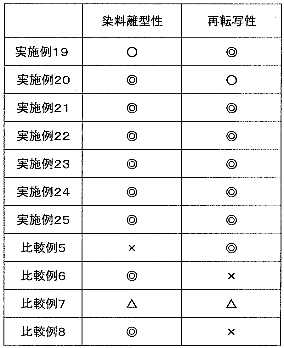
基材として厚さ12μmのPETフィルムを用い、該基材の一方の面へ、バーコーター法で、上記組成の剥離層形成用塗工液を、乾燥後0.8μmになるように塗布し乾燥して剥離層を形成した。次いで、この剥離層上に、バーコーター法で、上記組成の保護層形成用塗工液6を、乾燥後1.0μmになるように塗布し乾燥して第1の保護層を形成した。次いで第1の保護層上に、バーコーター法で、上記組成の保護層形成用塗工液12を、乾燥後10.0μmになるように塗布し乾燥して第2の保護層を形成した。次いで、第2の保護層上に、バーコーター法で、上記組成の受容層形成用塗工液6を、乾燥後2.5μmになるように塗布し乾燥して受容層を形成して、実施例26の中間転写媒体を得た。 (Example 26)
Using a PET film having a thickness of 12 μm as a base material, a coating solution for forming a release layer having the above composition is applied to one surface of the base material by a bar coater method so that the thickness becomes 0.8 μm after drying. Thus, a release layer was formed. Next, the protective layer-forming coating solution 6 having the above composition was applied onto the release layer so as to have a thickness of 1.0 μm after drying by a bar coater method, and dried to form a first protective layer. Next, a protective layer forming coating solution 12 having the above composition was applied onto the first protective layer by a bar coater method so as to have a thickness of 10.0 μm after drying, and dried to form a second protective layer. Next, on the second protective layer, the receiving layer forming coating solution 6 having the above composition was applied by drying so as to have a thickness of 2.5 μm and dried to form a receiving layer. The intermediate transfer medium of Example 26 was obtained.
上記第1の保護層の形成に際し、保護層形成用塗工液6を上記組成の保護層形成用塗工液9に変更した以外はすべて実施例26と同様にして実施例27の中間転写媒体を得た。 (Example 27)
The intermediate transfer medium of Example 27 is the same as Example 26 except that the protective layer forming coating solution 6 is changed to the protective layer forming coating solution 9 having the above composition when forming the first protective layer. Got.
上記第1の保護層の形成に際し、保護層形成用塗工液6を上記組成の保護層形成用塗工液9に変更し、上記第2の保護層の形成に際し、保護層形成用塗工液12を上記組成の保護層形成用塗工液14に変更した以外はすべて実施例26と同様にして実施例28の中間転写媒体を得た。 (Example 28)
In forming the first protective layer, the protective layer-forming coating solution 6 is changed to a protective layer-forming coating solution 9 having the above composition, and in forming the second protective layer, the protective layer-forming coating solution is formed. An intermediate transfer medium of Example 28 was obtained in the same manner as in Example 26 except that the liquid 12 was changed to the protective layer-forming coating liquid 14 having the above composition.
上記第1の保護層の形成に際し、保護層形成用塗工液6を上記組成の保護層形成用塗工液9に変更し、上記第2の保護層の形成に際し、保護層形成用塗工液12を上記組成の保護層形成用塗工液16に変更した以外はすべて実施例26と同様にして実施例29の中間転写媒体を得た。 (Example 29)
In forming the first protective layer, the protective layer-forming coating solution 6 is changed to a protective layer-forming coating solution 9 having the above composition, and in forming the second protective layer, the protective layer-forming coating solution is formed. An intermediate transfer medium of Example 29 was obtained in the same manner as in Example 26 except that the liquid 12 was changed to the protective layer-forming coating liquid 16 having the above composition.
厚さ12μmのポリエチレンテレフタレートフィルム(東レ株式会社製、ルミラー)上に、剥離層兼保護層として、上記保護層形成用塗工液14を乾燥状態で2.5μmの厚さとなるように塗工し剥離層兼保護層を形成した。次いで、剥離層兼保護層の上に、上記組成の保護層形成用塗工液9を、乾燥状態で1.0μmの厚さとなるように塗工し保護層を形成した。次いで、保護層上に上記組成の受容層形成用塗工液6を、乾燥状態で2.0μmの厚さとなるように塗工し受容層を形成して実施例30の中間転写媒体を得た。なお、剥離層兼保護層形成用塗工液14、保護層形成用塗工液9、受容層形成用塗工液6は、全てグラビアコーティングにて塗工した。 (Example 30)
On a 12 μm thick polyethylene terephthalate film (Lumirror, manufactured by Toray Industries, Inc.), the protective layer forming coating solution 14 is applied to a thickness of 2.5 μm in a dry state as a release layer and a protective layer. A release layer / protective layer was formed. Next, the protective layer-forming coating solution 9 having the above composition was applied on the release layer / protective layer to a thickness of 1.0 μm in a dry state to form a protective layer. Subsequently, the receiving layer-forming coating solution 6 having the above composition was applied on the protective layer so as to have a thickness of 2.0 μm in a dry state to form a receiving layer, whereby an intermediate transfer medium of Example 30 was obtained. . The release layer / protective layer forming coating solution 14, the protective layer forming coating solution 9, and the receiving layer forming coating solution 6 were all applied by gravure coating.
上記第1の保護層の形成に際し、保護層形成用塗工液6を上記組成の保護層形成用塗工液12に変更し、上記第2の保護層の形成に際し、保護層形成用塗工液12を、上記組成の保護層形成用塗工液9に変更した以外はすべて実施例26と同様にして実施例31の中間転写媒体を得た。 (Example 31)
In forming the first protective layer, the protective layer forming coating solution 6 is changed to the protective layer forming coating solution 12 having the above composition, and in forming the second protective layer, the protective layer forming coating solution is formed. An intermediate transfer medium of Example 31 was obtained in the same manner as in Example 26 except that the liquid 12 was changed to the protective layer-forming coating liquid 9 having the above composition.
上記第1の保護層の形成に際し、保護層形成用塗工液6を上記組成の保護層形成用塗工液11に変更し、上記第2の保護層の形成に際し、保護層形成用塗工液12を、上記組成の保護層形成用塗工液18に変更し、上記組成の受容層形成用塗工液6を上記組成の受容層形成用塗工液11に変更した以外はすべて実施例26と同様にして比較例9の中間転写媒体を得た。 (Comparative Example 9)
In forming the first protective layer, the protective layer forming coating solution 6 is changed to the protective layer forming coating solution 11 having the above composition, and in forming the second protective layer, the protective layer forming coating solution is formed. All the examples except that the liquid 12 was changed to the protective layer-forming coating liquid 18 having the above composition and the receiving layer-forming coating liquid 6 having the above composition was changed to the receiving layer-forming coating liquid 11 having the above composition. In the same manner as in No. 26, an intermediate transfer medium of Comparative Example 9 was obtained.
HDP-600(HID社製)プリンタと、該プリンタ用専用インクリボンを用い、実施例26~31、及び比較例9の中間転写媒体の受容層へ、黒ベタ画像を印画し、受容層に画像が印画された実施例26~31、及び比較例9の中間転写媒体を得た。 (Image formation)
Using a HDP-600 (manufactured by HID) printer and a dedicated ink ribbon for the printer, black solid images were printed on the receiving layers of the intermediate transfer media of Examples 26 to 31 and Comparative Example 9, and the images were received on the receiving layer. The intermediate transfer media of Examples 26 to 31 and Comparative Example 9 were printed.
受容層への画像を印画後、次いで、HDP-600(HID社)プリンタにより、塩ビカード(DNP社製)上に、画像が形成された実施例26~31、及び比較例9の中間転写媒体の転写層(保護層、受容層)を転写させ、実施例26~31、及び比較例9の印画物を得た。 <Image forming conditions>
After printing an image on the receiving layer, Examples 26 to 31 on which an image was formed on a vinyl chloride card (manufactured by DNP) by an HDP-600 (HID) printer, and the intermediate transfer media of Comparative Example 9 The transfer layers (protective layer and receiving layer) were transferred to obtain prints of Examples 26 to 31 and Comparative Example 9.

2…転写層
3…剥離層
4、40…保護層
304…積層構造の保護層
304A…耐可塑剤性層
304B…耐久性層
5、50…受容層
10、100、200、300…中間転写媒体 DESCRIPTION OF
Claims (8)
- 基材、2層以上の積層構造の保護層、受容層がこの順で積層されてなる中間転写媒体であって、
前記積層構造の保護層のうち、一の保護層が、数平均分子量(Mn)が12000以上、Tgが60℃以上の高重合度ポリエステル、ポリカーボネート、及びポリエステルウレタンの群から選択される1種、又は2種以上の混合物を主体として含有する耐久性層であり、他の一の保護層が、ポリビニルアルコール、ポリビニルブチラール、ポリビニルアセタール、及びポリビニルピロリドンからなる群より選択される1種又は2種以上、又は、カチオン性樹脂を含有する耐可塑剤性層であり、
前記受容層には、側鎖型アラルキル変性シリコーンが、前記受容層の全質量に対し0.5~5質量%の割合で含有されていることを特徴とする中間転写媒体。 An intermediate transfer medium in which a substrate, a protective layer having a laminated structure of two or more layers, and a receiving layer are laminated in this order,
Among the protective layers having the laminated structure, one protective layer is selected from the group consisting of high-polymerization polyester, polycarbonate, and polyester urethane having a number average molecular weight (Mn) of 12,000 or more and Tg of 60 ° C. or more, Or it is a durable layer which contains 2 or more types of mixtures as a main body, and 1 type, or 2 or more types as which one other protective layer is selected from the group which consists of polyvinyl alcohol, polyvinyl butyral, polyvinyl acetal, and polyvinylpyrrolidone Or a plasticizer-resistant layer containing a cationic resin,
The intermediate transfer medium, wherein the receiving layer contains a side chain type aralkyl-modified silicone in a proportion of 0.5 to 5% by mass with respect to the total mass of the receiving layer. - 前記積層構造の保護層は、前記基材側から、前記耐可塑剤性層と、前記耐久性層とが、この順で積層されてなることを特徴とする請求項1に記載の中間転写媒体。 2. The intermediate transfer medium according to claim 1, wherein the protective layer having the laminated structure is formed by laminating the plasticizer-resistant layer and the durable layer in this order from the base material side. .
- 前記基材と前記積層構造の保護層との間に剥離層が設けられていることを特徴とする請求項1又は2に記載の中間転写媒体。 The intermediate transfer medium according to claim 1, wherein a release layer is provided between the substrate and the protective layer having the laminated structure.
- 基材と、該基材の一方の面に少なくとも保護層、及び受容層がこの順で積層されてなる中間転写媒体であって、
前記保護層が、
ポリビニルアルコール、ポリビニルブチラール、ポリビニルアセタール、及びポリビニルピロリドンからなる群より選択される1種又は2種以上、
又は、カチオン性樹脂を含有することを特徴とする中間転写媒体。 An intermediate transfer medium comprising a base material and at least a protective layer and a receiving layer laminated in this order on one surface of the base material;
The protective layer is
One or more selected from the group consisting of polyvinyl alcohol, polyvinyl butyral, polyvinyl acetal, and polyvinyl pyrrolidone,
Alternatively, an intermediate transfer medium comprising a cationic resin. - 前記ポリビニルアルコール、ポリビニルブチラール、及びポリビニルアセタールのケン化度が、30~100%であることを特徴とする請求項4に記載の中間転写媒体。 The intermediate transfer medium according to claim 4, wherein the degree of saponification of the polyvinyl alcohol, polyvinyl butyral, and polyvinyl acetal is 30 to 100%.
- 基材と、該基材の一方の面に少なくとも保護層、及び受容層がこの順で積層されてなる中間転写媒体であって、
前記保護層が、数平均分子量(Mn)が12000以上、Tgが60℃以上の高重合度ポリエステル、ポリカーボネート、及びポリエステルウレタンの群から選択される1種、又は2種以上の混合物を主体として含有することを特徴とする中間転写媒体。 An intermediate transfer medium comprising a base material and at least a protective layer and a receiving layer laminated in this order on one surface of the base material;
The protective layer mainly contains one kind or a mixture of two or more selected from the group of high-polymerization polyester, polycarbonate, and polyester urethane having a number average molecular weight (Mn) of 12000 or more and Tg of 60 ° C. or more. An intermediate transfer medium characterized by: - 基材と、該基材の一方の面に少なくとも保護層、及び受容層が積層されてなる中間転写媒体であって、
前記受容層には、側鎖型アラルキル変性シリコーンが、前記受容層の全質量に対し0.5~5質量%の割合で含有されていることを特徴とする中間転写媒体。 An intermediate transfer medium comprising a base material and at least a protective layer and a receiving layer laminated on one surface of the base material,
The intermediate transfer medium, wherein the receiving layer contains a side chain type aralkyl-modified silicone in a proportion of 0.5 to 5% by mass with respect to the total mass of the receiving layer. - 側鎖型エポキシ変性シリコーンが、前記受容層の全質量に対し0.5~5質量%の割合で更に含有されていることを特徴とする請求項7に記載の中間転写媒体。 8. The intermediate transfer medium according to claim 7, further comprising a side chain type epoxy-modified silicone in a proportion of 0.5 to 5% by mass with respect to the total mass of the receiving layer.
Priority Applications (10)
| Application Number | Priority Date | Filing Date | Title |
|---|---|---|---|
| EP18183950.7A EP3409497A1 (en) | 2010-08-31 | 2011-08-23 | Intermediate transfer medium |
| EP11821607.6A EP2612762B1 (en) | 2010-08-31 | 2011-08-23 | Intermediate transfer medium |
| KR1020137002487A KR101809299B1 (en) | 2010-08-31 | 2011-08-23 | Intermediate transfer medium |
| KR1020177012845A KR101793883B1 (en) | 2010-08-31 | 2011-08-23 | Intermediate transfer medium |
| AU2011297246A AU2011297246B2 (en) | 2010-08-31 | 2011-08-23 | Intermediate transfer medium |
| EP18183905.1A EP3409496B1 (en) | 2010-08-31 | 2011-08-23 | Intermediate transfer medium |
| CN201180041854.9A CN103079832B (en) | 2010-08-31 | 2011-08-23 | Intermediate transfer medium |
| KR1020177012846A KR101793884B1 (en) | 2010-08-31 | 2011-08-23 | Intermediate transfer medium |
| US13/819,737 US8962112B2 (en) | 2010-08-31 | 2011-08-23 | Intermediate transfer medium |
| US14/586,304 US9597911B2 (en) | 2010-08-31 | 2014-12-30 | Intermediate transfer medium |
Applications Claiming Priority (8)
| Application Number | Priority Date | Filing Date | Title |
|---|---|---|---|
| JP2010-195083 | 2010-08-31 | ||
| JP2010195083A JP5083391B2 (en) | 2010-08-31 | 2010-08-31 | Intermediate transfer medium |
| JP2010-195080 | 2010-08-31 | ||
| JP2010195080A JP5056925B2 (en) | 2010-08-31 | 2010-08-31 | Intermediate transfer medium |
| JP2010-219781 | 2010-09-29 | ||
| JP2010219781A JP5104930B2 (en) | 2010-09-29 | 2010-09-29 | Intermediate transfer medium |
| JP2011172334A JP5003836B1 (en) | 2011-08-05 | 2011-08-05 | Intermediate transfer medium |
| JP2011-172334 | 2011-08-05 |
Related Child Applications (2)
| Application Number | Title | Priority Date | Filing Date |
|---|---|---|---|
| US13/819,737 A-371-Of-International US8962112B2 (en) | 2010-08-31 | 2011-08-23 | Intermediate transfer medium |
| US14/586,304 Division US9597911B2 (en) | 2010-08-31 | 2014-12-30 | Intermediate transfer medium |
Publications (1)
| Publication Number | Publication Date |
|---|---|
| WO2012029590A1 true WO2012029590A1 (en) | 2012-03-08 |
Family
ID=45772685
Family Applications (1)
| Application Number | Title | Priority Date | Filing Date |
|---|---|---|---|
| PCT/JP2011/068938 WO2012029590A1 (en) | 2010-08-31 | 2011-08-23 | Intermediate transfer medium |
Country Status (6)
| Country | Link |
|---|---|
| US (2) | US8962112B2 (en) |
| EP (3) | EP3409497A1 (en) |
| KR (3) | KR101809299B1 (en) |
| CN (3) | CN104859330B (en) |
| AU (1) | AU2011297246B2 (en) |
| WO (1) | WO2012029590A1 (en) |
Cited By (3)
| Publication number | Priority date | Publication date | Assignee | Title |
|---|---|---|---|---|
| CN103454867A (en) * | 2012-06-01 | 2013-12-18 | 富士施乐株式会社 | Image transfer sheet and image recording material |
| EP2902213A4 (en) * | 2012-09-26 | 2016-10-12 | Dainippon Printing Co Ltd | Intermediate transfer medium, and combination of intermediate transfer medium and heat transfer sheet |
| CN106660411A (en) * | 2014-08-08 | 2017-05-10 | 株式会社普利司通 | Pneumatic tire |
Families Citing this family (15)
| Publication number | Priority date | Publication date | Assignee | Title |
|---|---|---|---|---|
| WO2014157678A1 (en) | 2013-03-29 | 2014-10-02 | 大日本印刷株式会社 | Protective layer transfer sheet and intermediate transfer medium |
| KR102447667B1 (en) * | 2015-03-31 | 2022-09-26 | 다이니폰 인사츠 가부시키가이샤 | heat transfer sheet |
| US20180147813A1 (en) * | 2015-05-28 | 2018-05-31 | Dai Nippon Printing Co., Ltd. | Transfer film |
| GB2562015B (en) | 2016-02-25 | 2021-03-03 | Dainippon Printing Co Ltd | Combination of intermediate transfer sheet and thermal transfer medium, and print forming method |
| EP3741577B1 (en) * | 2016-03-08 | 2023-02-01 | Dai Nippon Printing Co., Ltd. | Thermal transfer sheet |
| EP3431303B1 (en) | 2016-03-18 | 2020-07-08 | Dai Nippon Printing Co., Ltd. | Intermediate transfer medium, combination of intermediate transfer medium and thermal transfer sheet, and method for forming print |
| WO2017170891A1 (en) * | 2016-03-31 | 2017-10-05 | 大日本印刷株式会社 | Heat transfer sheet |
| JPWO2018061741A1 (en) * | 2016-09-28 | 2019-08-15 | 富士フイルム株式会社 | Transfer film and image forming method |
| JP6743669B2 (en) * | 2016-12-06 | 2020-08-19 | 凸版印刷株式会社 | Protective layer transfer sheet and method for producing the same |
| EP3747660B1 (en) * | 2018-03-16 | 2022-10-26 | Dai Nippon Printing Co., Ltd. | Thermal transfer sheet, combination of intermediate transfer medium and thermal transfer sheet, and method for producing printed material |
| JP6579457B1 (en) * | 2018-06-29 | 2019-09-25 | 大日本印刷株式会社 | Intermediate transfer medium |
| JP6680429B1 (en) * | 2018-09-28 | 2020-04-15 | 大日本印刷株式会社 | Thermal transfer sheet and printed matter |
| DE102019127734A1 (en) * | 2019-10-15 | 2021-04-15 | Leonhard Kurz Stiftung & Co. Kg | Transfer film, component and process for their production |
| KR20220133269A (en) * | 2020-02-05 | 2022-10-04 | 다이니폰 인사츠 가부시키가이샤 | Release member-integrated sheet for image forming, edible food, and manufacturing method thereof |
| US20240075764A1 (en) * | 2022-09-01 | 2024-03-07 | Entrust Corporation | Personalized identification document processing systems and methods |
Citations (7)
| Publication number | Priority date | Publication date | Assignee | Title |
|---|---|---|---|---|
| JPS62238791A (en) | 1986-04-11 | 1987-10-19 | Dainippon Printing Co Ltd | Transfer printing sheet and decorating method therefor |
| JPH07156567A (en) | 1993-12-10 | 1995-06-20 | Dainippon Printing Co Ltd | Protective layer transferring film and printed matter |
| JP2002036795A (en) * | 2000-07-28 | 2002-02-06 | Toppan Printing Co Ltd | Method for painting transfer |
| JP2002222516A (en) * | 2001-01-26 | 2002-08-09 | Tomoegawa Paper Co Ltd | Magnetic recording medium |
| JP2004351656A (en) | 2003-05-27 | 2004-12-16 | Fujicopian Co Ltd | Intermediate transfer sheet for molten thermal transfer image recording |
| JP2005178098A (en) * | 2003-12-17 | 2005-07-07 | Dainippon Printing Co Ltd | Intermediate transfer recording medium |
| JP2009241587A (en) * | 2008-03-10 | 2009-10-22 | Toppan Printing Co Ltd | Thermal transfer sheet |
Family Cites Families (18)
| Publication number | Priority date | Publication date | Assignee | Title |
|---|---|---|---|---|
| JPH04259596A (en) * | 1991-02-13 | 1992-09-16 | Fuji Photo Film Co Ltd | Thermal transfer image receiving material |
| US5634731A (en) * | 1994-03-04 | 1997-06-03 | Dai Nippon Printing Co., Ltd. | Method and apparatus for thermal transfer printing |
| JP2000177282A (en) | 1998-12-14 | 2000-06-27 | Dainippon Printing Co Ltd | Printed matter and its manufacture |
| EP1013466A3 (en) * | 1998-12-22 | 2001-05-02 | E.I. Du Pont De Nemours And Company | Intermediate ink-receiver sheet for transfer printing |
| JP2000238439A (en) * | 1999-02-19 | 2000-09-05 | Dainippon Printing Co Ltd | Intermediate transfer recording medium and image forming method |
| JP2001105747A (en) * | 1999-10-14 | 2001-04-17 | Dainippon Printing Co Ltd | Heat-transfer dye image-receiving sheet and accepting layer transfer sheet |
| EP1188570B1 (en) * | 2000-09-14 | 2007-05-09 | Dai Nippon Printing Co., Ltd. | Intermediate transfer recording medium and method for image formation |
| TWI221127B (en) * | 2001-06-18 | 2004-09-21 | Toshiba Corp | Thermal transfer recording medium |
| JP3923793B2 (en) * | 2001-11-30 | 2007-06-06 | 大日本印刷株式会社 | Image forming method and image formed product |
| JP2005074821A (en) * | 2003-09-01 | 2005-03-24 | Dainippon Printing Co Ltd | Thermal transfer recording method and composite thermal transfer sheet |
| EP1702766B1 (en) * | 2003-12-24 | 2016-10-12 | Dai Nippon Printing Co., Ltd. | Thermal transfer sheet and method for producing same |
| US7179518B2 (en) * | 2004-05-10 | 2007-02-20 | Dai Nippon Printing Co., Ltd. | Protective layer transfer film, intermediate recording medium and printed matter |
| US7470649B2 (en) * | 2004-05-11 | 2008-12-30 | Konica Minolta Photo Imaging, Inc. | Thermal transfer image receiving sheet |
| DE602006012812D1 (en) * | 2005-03-18 | 2010-04-22 | Dainippon Printing Co Ltd | Thermal transfer image PAPER |
| CN101155695A (en) * | 2005-04-11 | 2008-04-02 | 王子制纸株式会社 | Thermal transfer receiving sheet |
| US7413783B2 (en) * | 2005-08-08 | 2008-08-19 | Fujicopian Co., Ltd. | Intermediate transfer sheet |
| ATE522364T1 (en) * | 2007-05-10 | 2011-09-15 | Jujo Paper Co Ltd | HEAT SENSITIVE RECORDING MATERIAL |
| JP5272577B2 (en) | 2008-08-21 | 2013-08-28 | 大日本印刷株式会社 | Thermal transfer image receiving sheet, image forming method and printed matter |
-
2011
- 2011-08-23 CN CN201510227816.2A patent/CN104859330B/en active Active
- 2011-08-23 AU AU2011297246A patent/AU2011297246B2/en not_active Ceased
- 2011-08-23 CN CN201510228068.XA patent/CN104802559B/en active Active
- 2011-08-23 EP EP18183950.7A patent/EP3409497A1/en active Pending
- 2011-08-23 KR KR1020137002487A patent/KR101809299B1/en active IP Right Grant
- 2011-08-23 EP EP11821607.6A patent/EP2612762B1/en active Active
- 2011-08-23 KR KR1020177012846A patent/KR101793884B1/en active IP Right Grant
- 2011-08-23 EP EP18183905.1A patent/EP3409496B1/en active Active
- 2011-08-23 US US13/819,737 patent/US8962112B2/en active Active
- 2011-08-23 WO PCT/JP2011/068938 patent/WO2012029590A1/en active Application Filing
- 2011-08-23 KR KR1020177012845A patent/KR101793883B1/en active IP Right Grant
- 2011-08-23 CN CN201180041854.9A patent/CN103079832B/en active Active
-
2014
- 2014-12-30 US US14/586,304 patent/US9597911B2/en active Active
Patent Citations (7)
| Publication number | Priority date | Publication date | Assignee | Title |
|---|---|---|---|---|
| JPS62238791A (en) | 1986-04-11 | 1987-10-19 | Dainippon Printing Co Ltd | Transfer printing sheet and decorating method therefor |
| JPH07156567A (en) | 1993-12-10 | 1995-06-20 | Dainippon Printing Co Ltd | Protective layer transferring film and printed matter |
| JP2002036795A (en) * | 2000-07-28 | 2002-02-06 | Toppan Printing Co Ltd | Method for painting transfer |
| JP2002222516A (en) * | 2001-01-26 | 2002-08-09 | Tomoegawa Paper Co Ltd | Magnetic recording medium |
| JP2004351656A (en) | 2003-05-27 | 2004-12-16 | Fujicopian Co Ltd | Intermediate transfer sheet for molten thermal transfer image recording |
| JP2005178098A (en) * | 2003-12-17 | 2005-07-07 | Dainippon Printing Co Ltd | Intermediate transfer recording medium |
| JP2009241587A (en) * | 2008-03-10 | 2009-10-22 | Toppan Printing Co Ltd | Thermal transfer sheet |
Cited By (5)
| Publication number | Priority date | Publication date | Assignee | Title |
|---|---|---|---|---|
| CN103454867A (en) * | 2012-06-01 | 2013-12-18 | 富士施乐株式会社 | Image transfer sheet and image recording material |
| EP2902213A4 (en) * | 2012-09-26 | 2016-10-12 | Dainippon Printing Co Ltd | Intermediate transfer medium, and combination of intermediate transfer medium and heat transfer sheet |
| EP3689632A1 (en) * | 2012-09-26 | 2020-08-05 | Dai Nippon Printing Co., Ltd. | Intermediate transfer medium |
| CN106660411A (en) * | 2014-08-08 | 2017-05-10 | 株式会社普利司通 | Pneumatic tire |
| US10787041B2 (en) | 2014-08-08 | 2020-09-29 | Bridgestone Corporation | Pneumatic tire with layered decorative portion on sidewall outer surface |
Also Published As
| Publication number | Publication date |
|---|---|
| US20130164463A1 (en) | 2013-06-27 |
| KR20140009963A (en) | 2014-01-23 |
| EP2612762A1 (en) | 2013-07-10 |
| US9597911B2 (en) | 2017-03-21 |
| EP3409496B1 (en) | 2020-03-11 |
| EP2612762B1 (en) | 2020-03-11 |
| KR20170057873A (en) | 2017-05-25 |
| CN103079832B (en) | 2015-09-02 |
| KR101793884B1 (en) | 2017-11-03 |
| CN103079832A (en) | 2013-05-01 |
| AU2011297246A1 (en) | 2013-03-28 |
| US8962112B2 (en) | 2015-02-24 |
| EP2612762A4 (en) | 2018-01-10 |
| CN104802559A (en) | 2015-07-29 |
| CN104859330A (en) | 2015-08-26 |
| KR101809299B1 (en) | 2017-12-14 |
| EP3409496A1 (en) | 2018-12-05 |
| CN104802559B (en) | 2018-05-08 |
| KR101793883B1 (en) | 2017-11-03 |
| KR20170057874A (en) | 2017-05-25 |
| AU2011297246B2 (en) | 2015-05-28 |
| US20150118420A1 (en) | 2015-04-30 |
| EP3409497A1 (en) | 2018-12-05 |
| CN104859330B (en) | 2017-09-22 |
Similar Documents
| Publication | Publication Date | Title |
|---|---|---|
| WO2012029590A1 (en) | Intermediate transfer medium | |
| JP5104930B2 (en) | Intermediate transfer medium | |
| EP2902213B1 (en) | Intermediate transfer medium | |
| JP5003836B1 (en) | Intermediate transfer medium | |
| JP5625633B2 (en) | Intermediate transfer medium | |
| JP5056925B2 (en) | Intermediate transfer medium | |
| WO2017146151A1 (en) | Combination of thermal transfer sheet and intermediate transfer medium, and method for forming printed matter | |
| JP5370517B2 (en) | Intermediate transfer medium | |
| WO2013129415A1 (en) | Intermediate transfer medium | |
| JP5703636B2 (en) | Intermediate transfer medium | |
| AU2018271238B2 (en) | Intermediate transfer medium | |
| JP5370516B2 (en) | Intermediate transfer medium | |
| JP6024513B2 (en) | Intermediate transfer medium | |
| JP5370518B2 (en) | Intermediate transfer medium |
Legal Events
| Date | Code | Title | Description |
|---|---|---|---|
| WWE | Wipo information: entry into national phase |
Ref document number: 201180041854.9 Country of ref document: CN |
|
| 121 | Ep: the epo has been informed by wipo that ep was designated in this application |
Ref document number: 11821607 Country of ref document: EP Kind code of ref document: A1 |
|
| ENP | Entry into the national phase |
Ref document number: 20137002487 Country of ref document: KR Kind code of ref document: A |
|
| NENP | Non-entry into the national phase |
Ref country code: DE |
|
| WWE | Wipo information: entry into national phase |
Ref document number: 13819737 Country of ref document: US |
|
| WWE | Wipo information: entry into national phase |
Ref document number: 2011821607 Country of ref document: EP |
|
| ENP | Entry into the national phase |
Ref document number: 2011297246 Country of ref document: AU Date of ref document: 20110823 Kind code of ref document: A |