WO2012020487A1 - 集積回路,障害情報処理方法および障害情報収集装置 - Google Patents
集積回路,障害情報処理方法および障害情報収集装置 Download PDFInfo
- Publication number
- WO2012020487A1 WO2012020487A1 PCT/JP2010/063656 JP2010063656W WO2012020487A1 WO 2012020487 A1 WO2012020487 A1 WO 2012020487A1 JP 2010063656 W JP2010063656 W JP 2010063656W WO 2012020487 A1 WO2012020487 A1 WO 2012020487A1
- Authority
- WO
- WIPO (PCT)
- Prior art keywords
- unit
- failure
- error
- information
- fault
- Prior art date
- Legal status (The legal status is an assumption and is not a legal conclusion. Google has not performed a legal analysis and makes no representation as to the accuracy of the status listed.)
- Ceased
Links
Images





Classifications
-
- G—PHYSICS
- G06—COMPUTING OR CALCULATING; COUNTING
- G06F—ELECTRIC DIGITAL DATA PROCESSING
- G06F11/00—Error detection; Error correction; Monitoring
- G06F11/07—Responding to the occurrence of a fault, e.g. fault tolerance
- G06F11/0703—Error or fault processing not based on redundancy, i.e. by taking additional measures to deal with the error or fault not making use of redundancy in operation, in hardware, or in data representation
- G06F11/0766—Error or fault reporting or storing
- G06F11/0772—Means for error signaling, e.g. using interrupts, exception flags, dedicated error registers
-
- G—PHYSICS
- G06—COMPUTING OR CALCULATING; COUNTING
- G06F—ELECTRIC DIGITAL DATA PROCESSING
- G06F11/00—Error detection; Error correction; Monitoring
- G06F11/07—Responding to the occurrence of a fault, e.g. fault tolerance
- G06F11/0703—Error or fault processing not based on redundancy, i.e. by taking additional measures to deal with the error or fault not making use of redundancy in operation, in hardware, or in data representation
- G06F11/0751—Error or fault detection not based on redundancy
Definitions
- This case relates to a fault information processing method in an integrated circuit.
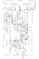
- FIG. 7 is a diagram illustrating a hardware configuration of the system 100.
- the system 100 includes an LSI 200 and a system controller 300.
- the LSI 200 includes a plurality of error detection modules 210 that detect errors in the LSI 200 and an error collection module 220 that notifies the system controller 300 of the occurrence of an error. Note that the error detection module 210 is included in each submodule that implements a specific function.
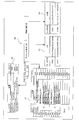
- FIG. 8 is a flowchart for explaining the operation of the system 100 when an error occurs.
- the error detection module 210 detects this error and notifies the error collection module 220 that an error has been detected (step B1).
- the error collection module 220 reports to the system controller 300 that an error has occurred in the LSI 200 (step B2).
- the system controller 300 collects information from storage units such as registers of all error detection modules 210 (step B3), and an administrator of the system 100 analyzes based on the collected information (step B3). B4).
- the system controller 300 clears the information stored in the storage unit such as a register of all the error detection modules 220 (step B5).
- the system controller 300 has to collect information from a large number of registers of the error detection modules 210 for error analysis. For this reason, it takes a lot of time to collect information, and as a result, it takes a lot of time to analyze an error.
- the present invention is not limited to the above-described object, and is a function and effect derived from each configuration shown in the embodiment for carrying out the present invention, which is another object of the present invention. Can be positioned as one.
- this integrated circuit is an integrated circuit including a fault collection unit and a plurality of modules, each of the plurality of modules including a fault detection unit that detects a fault in the module, and the fault
- a failure information generation unit that generates failure information related to the detected failure
- a failure detection notification indicating that the failure has been detected
- a notification unit for notifying the collection unit, the failure collection unit, based on the failure detection notification, among the plurality of modules, a specifying unit for identifying a module that first notified the failure detection notification,
- An acquisition unit that acquires the failure information from the module specified by the specifying unit;
- the fault information processing method is a fault information processing method in an integrated circuit including a fault collection unit and a plurality of modules, and each of the plurality of modules detects a fault in the module.
- a notification step of notifying the failure collection unit of a detection notification, and the failure collection unit selects a module that first notified the failure detection notification from the plurality of modules based on the failure detection notification.
- a specifying step for specifying and an acquiring step for acquiring the fault information from the module specified by the specifying step are provided.
- the fault information collection device includes a fault detection unit that detects a fault, a fault information generation unit that generates fault information related to the detected fault when the fault detection unit detects a fault, and the fault detection unit.
- a failure information collection device that collects a failure from a plurality of modules each including a notification unit that notifies the failure collection unit of a failure detection notification indicating that a failure has been detected, Based on the failure detection notification, among the plurality of modules, a specifying unit that identifies the module that first notified the failure detection notification, and an acquisition unit that acquires the failure information from the module specified by the specifying unit And have.
- the time required for failure analysis can be greatly reduced.
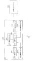
- FIG. 1 is a diagram illustrating a configuration of a system as an example of the embodiment
- FIG. 2 is a diagram illustrating configurations of a sub module and an error collection module as an example of the embodiment
- FIG. 3 is a diagram illustrating a sub as an example of the embodiment. It is a figure which shows the detailed structure of a module and an error collection module. It is. In addition, in FIG. 2, it shows that the block which has contact
- a system 1 as an example of this embodiment includes an LSI (integrated circuit) 2 and a system controller (external device) 3 as shown in FIG.
- the LSI 2 and the system controller 3 are communicably connected via a bus or the like.
- the LSI 2 is, for example, a processing circuit having a specific function.
- the LSI 2 includes a plurality of (five in the example illustrated in FIG. 1) submodules 4 and an error collection module (an example of a fault collection unit). 5 is provided.
- the submodule 4 is a module that realizes the function of the LSI.
- the submodule 4 includes a detection circuit group 41, an information holding unit 42, a generation unit 43, a local register 44, and an error channel 45 as illustrated in FIG. .
- the submodule 4 includes a detection circuit group 41, an information holding unit 42, a generation unit 43, a local register 44, and an error channel 45 as illustrated in FIG. .
- the submodule 4 includes a detection circuit group 41, an information holding unit 42, a generation unit 43, a local register 44, and an error channel 45 as illustrated in FIG. .
- FIG. 2 only two submodules 4 are illustrated for convenience, and the other submodules 4 are not illustrated.
- the detection circuit group 41 detects an error in the submodule 4 and outputs error information.
- the detection circuit group 41 includes a plurality of circuits for detecting a failure in the submodule 4.
- each of the plurality of circuits that detect a failure in the submodule 4 detects a different failure in the submodule 4 and, when detecting a failure, sets a flag indicating that the failure has been detected. That is, the detection circuit group 41 outputs error information with flags set at different positions depending on the type of failure.
- the error detection circuits 411-413 correspond to the detection circuit group 41 in FIG.
- the detection circuit group 41 includes three error detection circuits 411 to 413, but the present invention is not limited to this.
- Each of the error detection circuits 411 to 413 detects a specific failure in the submodule 4, and outputs a flag indicating that when a failure is detected. That is, the error detection circuits 411-413 function as a failure detection unit that detects a failure in the module. Note that the function of detecting a specific failure can be realized using various known methods, and detailed description thereof will be omitted.
- the information holding unit 42 is, for example, a register and holds error information output from the detection circuit group 41.
- the information holding unit 421 corresponds to the information holding unit 42 in FIG.
- the information holding unit 421 is a register, for example, and holds the output of the error detection circuits 411-413.
- the generating unit 43 processes the error information held in the information holding unit 42 to generate formatted error information (hereinafter, simply referred to as processed error information), and the local register 44. That is, the generation unit 43 functions as a failure information generation unit that generates failure information (processed error information).
- the generation unit 43 notifies the error collection module 5 of a part of the processed error information (in the example of the present embodiment, an error level and an error type described later).
- this notification may be referred to as error notification or failure detection notification. That is, it functions as a notification unit that notifies the failure collection unit of a failure detection notification indicating that a failure has been detected.
- the generation unit 43 creates processed error information by processing the error first detected by the detection circuit group 41 in the submodule 4.
- “first” in the specification of the present application means that each of the processed error information held by the global register 56 and the local register 44 and the information holding unit 42 after activation of the system 1 or as will be described later. After the error information held by is cleared.
- the grouping unit 431 groups error information held in the information holding unit 421. That is, the grouping unit 431 classifies error information according to the error detection circuits 411 to 413 that have detected an error. For example, consider a case where error information indicating that the error detection circuit 411 and the error detection circuit 412 have simultaneously detected a failure is held in the information holding unit 42. In this case, the grouping unit 431 classifies the error information into error information indicating a failure detected by the error detection circuit 411 and error information indicating a failure detected by the error detection circuit 412.
- the priority unit 432 gives priority to the error information classified by the grouping unit 431. For example, the priority unit 432 gives higher priority to the error information indicating the failure detected by the error detection circuit 411 than the error information indicating the failure detected by the error detection circuit 412.
- the first encoding unit 433 encodes the error information given the highest priority by the priority unit 432 and generates an error level indicating the importance of the error. For example, when the highest priority is given to the error information indicating the failure detected by the error detection circuit 411, the first encoding unit 433 displays the error information indicating the failure detected by the error detection circuit 411. Encode.
- the first encoding unit 433 may encode error information that has been given the highest priority by the priority unit 432 to generate an error type indicating the type of error.
- the error level output unit 434 outputs the error level generated by the first encoding unit 433, for example.
- the error type output unit 435 outputs the error type generated by the first encoding unit 433, for example.
- the module code output unit 436 outputs a module number for identifying each of the plurality of submodules 4.
- the module number is a fixed value determined in advance for each submodule 4.
- the second encoding unit 437 encodes the error information held in the information holding unit 421 to generate detailed information and outputs it.
- the detailed information is information indicating the detailed content of the error.
- the second encoding unit 437 indicates that a plurality of errors have occurred at the same time. Include information in detailed information.
- FIG. 4 is a diagram illustrating processed error information as an example of the embodiment.
- the processed error information 40 includes the error level, error type, module number, and detailed information described above.
- the error level is represented by 2 bits
- the error type is 4 bits
- the module number is 8 bits
- the detailed information is represented by 8 bits.
- the detection circuit group 41 detects a plurality of errors at the same time
- the second encoding unit 437 uses detailed information represented by 8 bits as information indicating that a plurality of errors have occurred at the same time. “1” is recorded at a predetermined position (for example, the most significant bit).
- the error level represented by 2 bits (“code” in the table 60) is information indicating the error level (“level” in the table 60) and details (tables) of the error level. 60, “details”).
- the code “2′b01” shown in the table 60 indicates that the error level is “System stop L1” and the details of the error level are “1 partition level”. That is, the code “2′b01” shown in the table 60 indicates that an error has occurred in one partition.
- the code “2′b00” shown in the table 60 indicates that the error level is “System“ stop L0 ”, and the details of the error level are“ active ”. That is, the code “2′b00” shown in the table 60 indicates that an error to be notified to the system controller 3 has not occurred.
- 2'b indicates that 2-bit data is represented by a binary number.
- the error type (“code” in the table 70) represented by 4 bits includes information indicating the error type (“type” in the table 70) and details of the error type ( “Details” in the table 70).
- the code “4′h1” shown in the table 70 indicates that the error type is “int_ce” and the details of the error type are “correctable internal errors”.
- the code “4′h0” shown in the table 70 indicates that the error type is “No“ Error ”and the details of the error type are“ no error ”. That is, the code “4′h0” shown in the table 70 indicates that an error to be notified to the system controller 3 has not occurred.
- the symbols “ce” and “ue” in the table 70 mean a collectable error and an uncorrectable error, respectively.
- 4'h indicates that 4-bit data is represented in hexadecimal.
- the module number (“code” in the table 80) represented by 8 bits is associated with the path to the submodule 4 (“path” in the table 80).
- the codes “8′h32” and “8′h11” in the table 80 indicate the paths “b1aaa / b2aaa / b3ccc / b4ttt” and “b1aaa / b2aaa / b3kkk / b4sss”, respectively.
- 8'h indicates that 8-bit data is represented in hexadecimal.
- the detailed information represented by 8 bits (“code” in the table 90) is associated with the content of the detailed information (“content” in the table 90).
- the codes “8′h01” and “8′h85” in the table 90 indicate “xxx counter parity error” and “yyy packet protocol error”, respectively.
- the tables 60, 70, 80, and 90 are not limited to these. Further, a part of the tables 60, 70, 80, 90 is omitted for convenience.
- the local register 44 is a register and stores processed error information generated by the generation unit 43. That is, the local register 44 functions as a first holding unit that holds failure information.
- the local register 441 corresponds to the local register 44 in FIG.
- the local register 441 holds outputs of the error level output unit 434, the error type output unit 435, the module code output unit 436, and the second encoding unit 437 as processed error information. Further, the local register 441 is connected to, for example, a transmission unit 451 to be described later, and holds the processed error information so that the transmission unit 451 can read the processed error information.
- the error channel 45 connects the submodule 4 and the error collection module 5 so that they can communicate with each other.
- the transmission unit 451, the D flip-flop (Delay flip-flop) 452-457, and the decoding unit 458 correspond to the error channel 45 of FIG.
- the submodule 4 includes a transmission unit 451 and D flip-flops 452-454
- the error collection module 5 includes a D flip-flop 455-457 and a decoding unit 458.
- the transmission unit 451 is connected to the D flip-flops 453, 454, the local register 441, and the information holding unit 421 so as to communicate with each other.
- the D flip-flops 452-454 and the D flip-flops 455-457 are connected so as to communicate with each other.
- the decoding unit 458 is connected to a D flip-flop 455 and an error grouping unit 531 described later so as to be communicable.
- the D flip-flop 452 is communicably connected to the error level output unit 434 and the error type output unit 435.
- the D flip-flops 456 and 457 are communicably connected to a selector 511 and an OR circuit 512, which will be described later.
- the transmission unit 451 reads out the processed error information from the local register 441 and transmits it to the error collection module 5 via the D flip-flops 454 and 457, for example, in response to an instruction from the control unit 551 described later. Further, the transmission unit 451 clears the information held in the information holding unit 421 and the local register 441 in response to an instruction from the control unit 551. That is, the transmission unit 451 functions as a first transmission unit that transmits failure information to the failure collection unit.
- Each of the D flip-flops 452-457 is provided for the purpose of timing relaxation, for example.
- the D flip-flop 452 and the D flip-flop 455 are connected by a 6-bit bus.
- the D flip-flop 453 and the D flip-flop 456, and the D flip-flop 454 and the D flip-flop 457 are connected by a 1-bit bus, respectively.
- the error channel 45 may not include the D flip-flops 452-457.
- the decoding unit 458 decodes the error notification notified from the error level output unit 434 and the error type output unit 435 and outputs the decoding result to an error grouping unit 531 described later and a control unit 551 described later.
- the error collection module 5 collects processed error information from the submodule 4 and transmits it to the system controller 3. Specifically, for example, the error collection module 5 determines the sub-module 4 that first made an error notification among the plurality of sub-modules 4 and holds the local register 44 of the sub-module 4 that made the error notification first. Collect processed error information.
- the error collection module 5 includes a gate 51, a collection unit 52, a sorting unit 53, a notification unit 54, a control unit 55, and a global register 56, as shown in FIG.
- the collection unit 52 bundles error notifications from the submodule 4.
- the collection unit 52 corresponds to a path connecting the error channel 45 to an error grouping unit 531 and a controller 551 described later.
- the sorting unit 53 performs grouping for error notifications from the submodule 4, for example. Specifically, the sorting unit 53 performs grouping for each error level and error type, for example.
- the error grouping unit 531 corresponds to the sorting unit 53 in FIG.
- the error grouping unit 531 receives an error notification from each submodule 4 and performs grouping for each error level and error type in response to the error notification from these submodules 4.
- the error grouping unit 531 outputs a result of grouping for each error level to a first priority unit 541 described later, and outputs a result of grouping for each error type to a second priority unit 542 described later.
- reference numerals S1-S3 indicate paths through which signals representing different error levels classified by the error grouping unit 531 are transmitted. Further, in FIG. 3, reference numerals S4-Sn (n is a natural number) indicate paths through which signals representing different error types classified by the error grouping unit 531 are transmitted.
- the notification unit 54 notifies the system controller 3 and the control unit 55 described later that an error for which processed error information should be collected (hereinafter, referred to as “error”). Simply called a collection notification).
- error an error for which processed error information should be collected
- simply called a collection notification simply called a collection notification.
- the first priority unit 541, the second priority unit 542, the OR circuit 543, the overview register 544, and the warning register 545 correspond to the notification unit 54 in FIG.
- the first priority unit 541 assigns priorities to a plurality of error levels classified by the error grouping unit 531. For example, the first priority unit 541 gives a high priority to a serious error. For example, if the error level assigned the highest priority is an error level equal to or higher than a predetermined threshold, the first priority unit 541 outputs the error level to the OR circuit 543 and the control unit 55 as a collection notification. Further, the first priority unit 541, when the error level with the highest priority is less than a predetermined threshold value, indicates a value (for example, “ 0 ′′) is output to the OR circuit 543 and the control unit 55.
- a predetermined threshold value indicates a value (for example, “ 0 ′′) is output to the OR circuit 543 and the control unit 55.
- the first priority unit 541 outputs a collection notification to the OR circuit 543 and the control unit 55 when the highest priority error level is equal to or higher than a predetermined threshold.
- the first priority unit 541 does not output the collection notification to the OR circuit 543 and the control unit 55 when the highest priority error level is less than a predetermined threshold.
- the administrator of the system 1 can control the output of the first priority unit 541 by setting the error level threshold to an arbitrary value.
- the second priority unit 542 gives priority to a plurality of error types classified by the error grouping unit 531.
- the second priority unit 542 gives a high priority to a serious error.
- the error types assigned priority by the second priority unit 542 are recorded in the error summary register 544.
- the second priority unit 542 can output the error type having the highest priority to the OR circuit 543 and the control unit 55 as a collection notification.
- the OR circuit 543 calculates the logical sum of the output of the first priority unit 541 and the output of the second priority unit 542 and notifies the system controller 3 of the logical sum.
- the output of the OR circuit 543 is recorded in the warning register 545, for example.
- the control unit 55 determines the sub-module 4 that first made an error notification among the plurality of sub-modules 4.
- the control unit 55 receives error notifications simultaneously from a plurality of submodules 4, for example, the control unit 55 first sends an error notification to the submodule 4 that made the error notification including the highest error level among these error notifications. It is determined that the submodule 4 has been performed.
- the control unit 55 functions as a specifying unit that identifies a module that has first notified the failure detection notification among a plurality of modules based on the failure detection notification.
- control unit 55 instructs the transmission unit 451 to transmit the processed error information from the local register 44 of the submodule 4 that first notified the error. As a result, the processed error information is acquired. That is, the control unit 55 functions as an acquisition unit that acquires failure information from the module specified by the specifying unit.
- the control unit 55 when receiving an instruction from the system controller 3 to transmit the processed error information to the system controller 3, the control unit 55 reads the processed error information from the global register 56 and transmits it to the system controller 3. That is, the control unit 55 functions as a second transmission unit that transmits failure information to an external device. The control unit 55 also instructs the system controller 3 to clear the processed error information held in the global register 56 and the local register 44 and the error information held in the information holding unit 42 (hereinafter simply referred to as a clear instruction). May be received). When receiving the clear instruction from the system controller 3, the control unit 55 instructs the transmission unit 451 to clear the information held in each of the information holding unit 42 and the local register 44, and The processed error information held by 56 is cleared.
- control unit 551 and the conversion unit 552 correspond to the control unit 55 in FIG. 2.
- an error notification is input from the submodule 4 to the control unit 551.
- the control unit 551 uses the output of the first priority unit 541 or the summary register 544, that is, the output (collection notification) of the second priority unit 542 as a trigger, and the sub module that first performs error notification among the plurality of sub modules 4 4 is judged.
- the control unit 551 uses the output of the first priority unit 541 or the summary register 544, that is, the output of the second priority unit 542 as a trigger, and sends a local register to the transmission unit 451 of the submodule 4 that first notified the error.
- An instruction to transmit processed error information is issued from 441.
- control unit 551 instructs the selector 511, which will be described later, to connect the control unit 551 and the error channel 45 provided by the submodule 4 that first made an error notification so that they can communicate with each other. (Channel designation). Thereafter, the control unit 551 instructs the transmission unit 451 provided in the submodule 4 that has first notified the error to transmit the processed error information from the local register 441.
- the control unit 551 sets a flag at a different position when the error notification is received for each of the plurality of submodules 4. Based on the position of the flag, the control unit 551 Of these, the sub-module 4 that first notified the error is determined.
- the control unit 551 includes a memory capable of setting a flag, for example.
- the conversion unit 552 is, for example, a serial / parallel converter, performs serial / parallel conversion on the processed error information transmitted from the transmission unit 451, and stores it in the global register 56.
- the gate 51 switches the error channel 45 connected to the control unit 55 in accordance with an instruction from the control unit 55.
- the selector 511 and the OR circuit 512 correspond to the gate 51 in FIG.
- the selector 511 switches the error channel 45 connected to the control unit 551 in response to an instruction from the control unit 551.
- the selector 511 switches the error channel 45 connected to the control unit 551 in accordance with an instruction from the control unit 551.
- the OR circuit 512 calculates the logical sum of the processed error information transmitted from each submodule 4. Since the processed error information is not simultaneously transmitted from the plurality of submodules 4, the processed error information is input from one submodule 4 to the OR circuit 512, and the other submodules 4 receive the processed error information. No signal is input (that is, “0” is input).
- the global register 56 is a register, and holds processed error information read from the local register 44 and transmitted by the transmission unit 451. That is, the global register 56 functions as a second holding unit that holds failure information.
- the global register 561 corresponds to the global register 56 in FIG.
- the global register 561 stores processed error information obtained by converting a serial signal into a parallel signal by the conversion unit 552.
- the system controller 3 receives processed error information from the error collection module 5 and analyzes an error based on the processed error information.
- FIG. 5 is a diagram showing the configuration of the system controller 3.
- the system controller 3 includes a processing unit 31 and a storage unit 32.
- the storage unit 32 is a storage device such as a ROM (Read Only Memory) or a RAM (Random Access Memory), and stores various types of information.
- the processing unit 31 is a processing device that performs various calculations and controls by executing various application programs stored in the storage unit 32 and realizes various functions.
- the processing unit 31 functions as an instruction unit 311 and an analysis unit 312 as illustrated in FIG. 6 by executing an application program.
- the instruction unit 311 instructs the control unit 55 to transmit the processed error information, and acquires the processed error information.
- the instruction unit 311 instructs the control unit 55 to clear the processed error information held by the global register 56 and the local register 44 and the error information held by the information holding unit 42.
- the analysis unit 312 analyzes an error based on the processed error information transmitted by the control unit 55.
- the analysis unit 312 can be realized by using various known methods, and detailed description thereof is omitted.
- step A1-A22 A failure information processing method of the system 1 as an example of the embodiment configured as described above will be described with reference to a flowchart (step A1-A22) shown in FIG.
- the detection circuit group 41 detects an error and outputs error information, and stores this error information in the information holding unit 42 (step A1).
- the generation unit 43 generates processed error information (step A2) and stores the processed error information in the local register 44 (step A3).
- the generation unit 43 sends an error notification to the error collection module 5 (step A4).
- the error collection module 5 receives the error notification decoded in the error channel 45 (step A5).
- the notification unit 54 determines whether or not to transmit the collection notification based on the error notification grouped for each error level and error type by the sorting unit 53 ( Step A6). For example, when the error level included in the error notification is equal to or higher than a predetermined threshold (see YES route in step A6), the notification unit 54 performs collection notification to the system controller 3 and the control unit 55 (step A7). ). The control unit 55 that has received the collection notification determines the sub-module 4 that has first notified the error among the plurality of sub-modules 4, and the sub-module 4 that has first notified the error to the gate 51. Is instructed to connect to the error channel 45.
- the gate 51 connects the control unit 55 and the error channel 45 of the submodule 4 that first made an error notification.
- the control unit 55 instructs the transmission unit 451 provided by the submodule 4 that first notified the error to transmit the processed error information (step A8).
- the transmission unit 451 Upon receiving an instruction from the control unit 55 (step A9), the transmission unit 451 reads the processed error information from the local register 44 and transmits it to the error collection module 5 via the error channel 45 (step A10).
- the control unit 55 stores the processed error information in the global register 56 (step A12).
- the system controller 3 instructs the control unit 55 to transmit the processed error information to the system controller 3 (step A14).
- the control unit 55 reads out the processed error information from the global register 56 and transmits it to the system controller 3 (step A16).
- the system controller 3 receives the processed error information (step A17)
- the system controller 3 analyzes the processed error information. Thereafter, the control unit 55 is instructed to clear the information held in the global register 56, the local register 44, and the information holding unit 42 (step A18).
- control unit 55 When the control unit 55 receives an instruction from the system controller 3 (step A19), the control unit 55 clears the information held in the global register 56, and also controls the control unit 55 and the error channels 45 of all the submodules 4 with respect to the gate 51. And instruct them to connect. Then, the control unit 55 instructs all the submodules 4, specifically the transmission unit 451, to clear the information held in the local register 44 and the information holding unit 42 (step A20). When receiving the instruction from the control unit 55 (step A21), the transmission unit 451 clears the information held in the local register 44 and the information holding unit 42 (step A22).
- step A6 If it is determined in step A6 that the collection notification is not performed (see the NO route in step A6), the process ends without performing the collection notification.
- the error collection module 5 determines the sub-module 4 that first notified the error collection module 5 of the plurality of sub-modules 4. Then, the error collection module 5 acquires processed error information from the submodule 4 that first made an error notification to the error collection module 5. Thereby, in order to analyze the cause of the error, the processed error information held by the error collection module 5 may be acquired, and unnecessary information may not be acquired. Therefore, the time required for collecting information for error analysis can be greatly reduced.
- the system controller 3 acquires processed error information from the error collection module 5 and analyzes an error based on the processed error information, the system controller 3 does not have any submodule 4 in the LSI 2. There is no need to read the register, and as a result, the time required for error analysis can be greatly reduced.
- the processed error information is generated by the generation unit 43 based on the error first detected by the detection circuit group 41. Then, the system controller 3 analyzes the error based on the processed error information acquired from the submodule 4 that first notified the error collection module 5 of the error. Therefore, this analysis can reliably identify the cause of the error.
- the generation unit 43 notifies the error collection module 5 of the error level and the error type as an error notification.
- the present invention is not limited to this.
- the generation unit 43 may notify only the error level to the error collection module 5 as the error notification.
- the generation unit 43 generates an error level based on the error information that is given the highest priority by the priority unit 432, and generates processed error information having this error level.
- the present invention is not limited to this.
- a plurality of error levels are generated from the higher priority given by the priority unit 432, and the generation unit 43 generates a plurality of error levels.
- Processed error information may be generated.
- a plurality of error levels are similarly generated for the error type from the top of the priority order given by the priority unit 432.
- the error collection module 5 includes the OR circuit 512
- a selector that selectively connects the error channel 45 and the conversion unit 552 may be used instead of the OR circuit 512. Note that selector switching is performed based on channel designation input from the control unit 55 to the selector 511.
- the system controller 3 uses, for example, a submodule 4 via a system bus (not shown). The error information may be acquired from the information holding unit 42.
- the system controller 3 analyzes the error based on the processed error information, but the present invention is not limited to this.
- the administrator of the system 1 may acquire processed error information from the system controller 3 and perform analysis.
Landscapes
- Engineering & Computer Science (AREA)
- Theoretical Computer Science (AREA)
- Quality & Reliability (AREA)
- Physics & Mathematics (AREA)
- General Engineering & Computer Science (AREA)
- General Physics & Mathematics (AREA)
- Debugging And Monitoring (AREA)
Abstract
障害収集部(5)と、複数のモジュール(4)と、を備えた集積回路であって、複数のモジュール(4)のそれぞれは、モジュール内の障害を検出する障害検出部(41)と、検出した障害に係る障害情報を生成する障害情報生成部(43)と、障害を検出したことを示す障害検出通知を、障害収集部(5)に通知する通知部(43)と、障害情報を障害収集部(5)に送信する第1送信部(451)と、をそなえ、障害収集部(5)は、障害検出通知に基づいて、複数のモジュール(4)のうち、最初に障害検出通知を通知したモジュール(4)を特定する特定部(55)と、特定部(55)によって特定されたモジュール(4)から、障害情報を取得する取得部(55)と、をそなえる。
Description
本件は、集積回路における障害情報処理方法に関する。
LSI(Large Scale Integration)等の内部においてエラー(障害)が発生した場合、このエラーに係る情報を収集し、収集された情報に基づいて、専門のオペレータが、エラーを解析する技術が知られている。
ここで、LSI等の内部においてエラーが発生した場合における、システムの動作を図7および図8を用いて説明する。図7はシステム100のハードウェア構成を示す図である。システム100は、LSI200と、システムコントローラ300とをそなえる。LSI200は、LSI200におけるエラーを検出するエラー検出モジュール210を複数そなえるとともに、システムコントローラ300にエラーの発生を通知するエラー収集モジュール220をそなえる。なお、エラー検出モジュール210は、特定の機能を実現するサブモジュールにそれぞれ含まれる。
ここで、LSI等の内部においてエラーが発生した場合における、システムの動作を図7および図8を用いて説明する。図7はシステム100のハードウェア構成を示す図である。システム100は、LSI200と、システムコントローラ300とをそなえる。LSI200は、LSI200におけるエラーを検出するエラー検出モジュール210を複数そなえるとともに、システムコントローラ300にエラーの発生を通知するエラー収集モジュール220をそなえる。なお、エラー検出モジュール210は、特定の機能を実現するサブモジュールにそれぞれ含まれる。
図8は、エラーが発生した場合のシステム100の動作を説明するためのフローチャートである。まず、LSI200においてエラーが発生すると、エラー検出モジュール210は、このエラーを検出するとともに、エラー収集モジュール220にエラーを検出した旨を通知する(ステップB1)。この通知を受けたエラー収集モジュール220は、LSI200においてエラーが発生した旨を、システムコントローラ300に報告する(ステップB2)。この報告を受けたシステムコントローラ300は、全てのエラー検出モジュール210のレジスタ等の記憶部から情報を採取し(ステップB3)、採取した情報に基づいてシステム100の管理者等が解析を行なう(ステップB4)。解析終了後、システムコントローラ300は、全てのエラー検出モジュール220のレジスタ等の記憶部に記憶された情報をクリアする(ステップB5)。
しかしながら、LSI200の回路規模が大きくなるにつれ、サブモジュールの数が増大する。すなわち、エラー検出モジュール210の数が増大するため、システムコントローラ300は、エラーの解析のために、非常に多くのエラー検出モジュール210のレジスタから、情報を採取しなければならない。そのため、情報を採取するために多大な時間を要し、その結果、エラーの解析に多大な時間を要するという問題点があった。
本件は、エラーの解析のための情報収集に要する時間を大幅に短縮することを目的の一つとする。
なお、前記目的に限らず、後述する発明を実施するための形態に示す各構成により導かれる作用効果であって、従来の技術によっては得られない作用効果を奏することも本件の他の目的の1つとして位置付けることができる。
なお、前記目的に限らず、後述する発明を実施するための形態に示す各構成により導かれる作用効果であって、従来の技術によっては得られない作用効果を奏することも本件の他の目的の1つとして位置付けることができる。
このため、この集積回路は、障害収集部と、複数のモジュールと、を備えた集積回路であって、該複数のモジュールのそれぞれは、該モジュール内の障害を検出する障害検出部と、該障害検出部で障害を検出した場合、検出した障害に係る障害情報を生成する障害情報生成部と、該障害検出部で障害を検出した場合、障害を検出したことを示す障害検出通知を、該障害収集部に通知する通知部と、をそなえ、該障害収集部は、該障害検出通知に基づいて、該複数のモジュールのうち、最初に該障害検出通知を通知したモジュールを特定する特定部と、該特定部によって特定されたモジュールから、該障害情報を取得する取得部と、をそなえる。
また、この障害情報処理方法は、障害収集部と、複数のモジュールと、を備えた集積回路における障害情報処理方法であって、該複数のモジュールのそれぞれが、該モジュール内の障害を検出する障害検出ステップと、該障害検出ステップで障害を検出した場合、検出した障害に係る障害情報を生成する障害情報生成ステップと、該障害検出ステップで障害を検出した場合、障害を検出したことを示す障害検出通知を、該障害収集部に通知する通知ステップと、をそなえ、該障害収集部は、該障害検出通知に基づいて、該複数のモジュールのうち、最初に該障害検出通知を通知したモジュールを特定する特定ステップと、該特定ステップによって特定されたモジュールから、該障害情報を取得する取得ステップと、をそなえる。
さらに、この障害情報収集装置は、障害を検出する障害検出部と、該障害検出部で障害を検出した場合、検出した障害に係る障害情報を生成する障害情報生成部と、該障害検出部で障害を検出した場合、障害を検出したことを示す障害検出通知を、該障害収集部に通知する通知部と、をそれぞれ備えた複数のモジュールから、障害を収集する障害情報収集装置であって、該障害検出通知に基づいて、該複数のモジュールのうち、最初に該障害検出通知を通知したモジュールを特定する特定部と、該特定部によって特定されたモジュールから、該障害情報を取得する取得部と、をそなえる。
開示の集積回路,障害情報処理方法および障害情報収集装置によれば、障害の解析に要する時間を大幅に短縮することができる。
以下、図面を参照して本集積回路,障害情報処理方法および障害情報収集装置に係る実施形態の一例を説明する。
図1は、実施形態の一例としてのシステムの構成を示す図、図2は、実施形態の一例としてのサブモジュールおよびエラー収集モジュールの構成を示す図、図3は、実施形態の一例としてのサブモジュールおよびエラー収集モジュールの詳細な構成を示す図である。である。なお、図2において、接しているブロック同士は通信可能に接続されていることを示す。例えば、図2において、情報保持部42と生成部43とは通信可能に接続されていることを示す。
図1は、実施形態の一例としてのシステムの構成を示す図、図2は、実施形態の一例としてのサブモジュールおよびエラー収集モジュールの構成を示す図、図3は、実施形態の一例としてのサブモジュールおよびエラー収集モジュールの詳細な構成を示す図である。である。なお、図2において、接しているブロック同士は通信可能に接続されていることを示す。例えば、図2において、情報保持部42と生成部43とは通信可能に接続されていることを示す。
本実施形態の一例としてのシステム1は、図1に示すように、LSI(集積回路)2とシステムコントローラ(外部装置)3とをそなえる。LSI2とシステムコントローラ3とはバス等を介して通信可能に接続されている。
LSI2は、例えば、特定の機能を有する処理回路であり、本実施形態の一例においては、複数の(図1に示す例では5つの)サブモジュール4と、エラー収集モジュール(障害収集部の一例)5とをそなえる。
LSI2は、例えば、特定の機能を有する処理回路であり、本実施形態の一例においては、複数の(図1に示す例では5つの)サブモジュール4と、エラー収集モジュール(障害収集部の一例)5とをそなえる。
サブモジュール4は、LSIの機能を実現するモジュールである。この機能を実現する回路(図示省略)の他に、サブモジュール4は、図2に例示するように、検出回路群41,情報保持部42,生成部43,ローカルレジスタ44およびエラーチャネル45をそなえる。
なお、図2に示す例では、便宜上、2つのサブモジュール4のみを記載し、他のサブモジュール4については、図示を省略している。
なお、図2に示す例では、便宜上、2つのサブモジュール4のみを記載し、他のサブモジュール4については、図示を省略している。
検出回路群41は、サブモジュール4内のエラーを検出するとともに、エラー情報を出力する。検出回路群41は、例えば、サブモジュール4内の障害を検出する回路を複数そなえる。例えば、サブモジュール4内の障害を検出する複数の回路のそれぞれは、サブモジュール4内の異なる障害を検出し、障害を検出した場合、障害を検出した旨を示すフラグを設定する。すなわち、検出回路群41は、障害の種類に応じて、異なる位置にフラグが立ったエラー情報を出力する。
図3に示す例では、エラー検出回路411-413が、図2の検出回路群41に相当する。図3に示す例では、検出回路群41は、3つのエラー検出回路411-413をそなえているが、これに限定されるものではない。
エラー検出回路411-413のそれぞれは、サブモジュール4における特定の障害を検出し、障害を検出した場合、その旨を示すフラグを出力する。すなわち、エラー検出回路411-413は、モジュール内の障害を検出する障害検出部として機能する。なお、特定の障害を検出する機能は、既知の種々の手法を用いて実現可能であり、その詳細な説明については省略する。
エラー検出回路411-413のそれぞれは、サブモジュール4における特定の障害を検出し、障害を検出した場合、その旨を示すフラグを出力する。すなわち、エラー検出回路411-413は、モジュール内の障害を検出する障害検出部として機能する。なお、特定の障害を検出する機能は、既知の種々の手法を用いて実現可能であり、その詳細な説明については省略する。
情報保持部42は、例えば、レジスタであり、検出回路群41が出力するエラー情報を保持する。図3に示す例では、情報保持部421が、図2の情報保持部42に相当する。
情報保持部421は、例えば、レジスタであり、エラー検出回路411-413の出力を保持する。
生成部43は、情報保持部42に保持されたエラー情報に対して処理を行なうことで、フォーマット化されたエラー情報(以下、単に、処理済エラー情報という場合がある)を生成し、ローカルレジスタ44に保存する。すなわち、生成部43は、障害情報(処理済エラー情報)を生成する障害情報生成部として機能する。
情報保持部421は、例えば、レジスタであり、エラー検出回路411-413の出力を保持する。
生成部43は、情報保持部42に保持されたエラー情報に対して処理を行なうことで、フォーマット化されたエラー情報(以下、単に、処理済エラー情報という場合がある)を生成し、ローカルレジスタ44に保存する。すなわち、生成部43は、障害情報(処理済エラー情報)を生成する障害情報生成部として機能する。
また、生成部43は、処理済エラー情報の一部(本実施形態の一例では、後述するエラーレベルおよびエラータイプ)をエラー収集モジュール5に通知する。以下、この通知をエラー通知もしくは障害検出通知という場合がある。すなわち、障害を検出したことを示す障害検出通知を、障害収集部に通知する通知部として機能する。
なお、生成部43は、サブモジュール4内で最初に検出回路群41によって検出されたエラーに対して処理を行なうことで処理済エラー情報を作成する。ここで、本願明細書中における、「最初」とは、システム1の起動後、または、後述するように、グローバルレジスタ56およびローカルレジスタ44が保持する各処理済エラー情報、および、情報保持部42が保持するエラー情報がクリアされた後を指す。
なお、生成部43は、サブモジュール4内で最初に検出回路群41によって検出されたエラーに対して処理を行なうことで処理済エラー情報を作成する。ここで、本願明細書中における、「最初」とは、システム1の起動後、または、後述するように、グローバルレジスタ56およびローカルレジスタ44が保持する各処理済エラー情報、および、情報保持部42が保持するエラー情報がクリアされた後を指す。
図3に示す例では、グルーピング部431,プライオリティ部432,第1エンコード部433,エラーレベル出力部434,エラータイプ出力部435,モジュールコード出力部436および第2エンコード部437が、図2の生成部43に相当する。
グルーピング部431は、例えば、情報保持部421に保持されたエラー情報のグルーピングを行なう。すなわち、グルーピング部431は、エラーを検出したエラー検出回路411-413に応じて、エラー情報の分類を行なう。例えば、エラー検出回路411とエラー検出回路412とが同時に障害を検出した旨を示すエラー情報が情報保持部42に保持されている場合を考える。この場合、グルーピング部431は、エラー検出回路411が検出した障害を示すエラー情報と、エラー検出回路412が検出した障害を示すエラー情報とにエラー情報を分類する。
グルーピング部431は、例えば、情報保持部421に保持されたエラー情報のグルーピングを行なう。すなわち、グルーピング部431は、エラーを検出したエラー検出回路411-413に応じて、エラー情報の分類を行なう。例えば、エラー検出回路411とエラー検出回路412とが同時に障害を検出した旨を示すエラー情報が情報保持部42に保持されている場合を考える。この場合、グルーピング部431は、エラー検出回路411が検出した障害を示すエラー情報と、エラー検出回路412が検出した障害を示すエラー情報とにエラー情報を分類する。
プライオリティ部432は、例えば、グルーピング部431によって分類されたエラー情報に対して、優先順位を付ける。例えば、プライオリティ部432は、エラー検出回路411が検出した障害を示すエラー情報に対して、エラー検出回路412が検出した障害を示すエラー情報より高い優先順位を付ける。
第1エンコード部433は、プライオリティ部432によって最も高い優先順位が付けられたエラー情報をエンコードして、エラーの重要度を示すエラーレベルを生成する。例えば、エラー検出回路411が検出した障害を示すエラー情報に対して最も高い優先順位が付けられている場合には、第1エンコード部433は、エラー検出回路411が検出した障害を示すエラー情報をエンコードする。
第1エンコード部433は、プライオリティ部432によって最も高い優先順位が付けられたエラー情報をエンコードして、エラーの重要度を示すエラーレベルを生成する。例えば、エラー検出回路411が検出した障害を示すエラー情報に対して最も高い優先順位が付けられている場合には、第1エンコード部433は、エラー検出回路411が検出した障害を示すエラー情報をエンコードする。
また、第1エンコード部433は、プライオリティ部432によって最も高い優先順位が付けられたエラー情報をエンコードして、エラーの種類を示すエラータイプを生成することもできる。
エラーレベル出力部434は、例えば、第1エンコード部433によって生成されたエラーレベルを出力する。
エラーレベル出力部434は、例えば、第1エンコード部433によって生成されたエラーレベルを出力する。
エラータイプ出力部435は、例えば、第1エンコード部433によって生成されたエラータイプを出力する。
モジュールコード出力部436は、複数のサブモジュール4のそれぞれを識別するためのモジュール番号を出力する。モジュール番号とは、サブモジュール4毎に予め定められた固定の値である。
モジュールコード出力部436は、複数のサブモジュール4のそれぞれを識別するためのモジュール番号を出力する。モジュール番号とは、サブモジュール4毎に予め定められた固定の値である。
第2エンコード部437は、情報保持部421に保持されたエラー情報をエンコードして詳細情報を生成し、出力する。ここで、詳細情報とは、エラーの詳細な内容を示す情報である。また、情報保持部421に保持されたエラー情報が、検出回路群41が同時に複数のエラーを検出したことを示す場合には、第2エンコード部437は、同時に複数のエラーが発生したことを示す情報を詳細情報に含める。
図4は、実施形態の一例としての処理済エラー情報を示す図である。
処理済エラー情報40は、上述したエラーレベル、エラータイプ、モジュール番号および詳細情報をそなえる。
図4に示す例では、エラーレベルは2ビット、エラータイプは4ビット、モジュール番号は8ビット、詳細情報は8ビットでそれぞれ表される。ここで、検出回路群41が同時に複数のエラーを検出した場合には、例えば、第2エンコード部437は、同時に複数のエラーが発生したことを示す情報として、8ビットで表される詳細情報の所定の位置(例えば、最上位ビット)に“1”を記録する。
処理済エラー情報40は、上述したエラーレベル、エラータイプ、モジュール番号および詳細情報をそなえる。
図4に示す例では、エラーレベルは2ビット、エラータイプは4ビット、モジュール番号は8ビット、詳細情報は8ビットでそれぞれ表される。ここで、検出回路群41が同時に複数のエラーを検出した場合には、例えば、第2エンコード部437は、同時に複数のエラーが発生したことを示す情報として、8ビットで表される詳細情報の所定の位置(例えば、最上位ビット)に“1”を記録する。
なお、テーブル60に例示するように、2ビットで表されるエラーレベル(テーブル60中の「コード」)は、エラーレベルを示す情報(テーブル60中の「レベル」)とエラーレベルの詳細(テーブル60中の「詳細」)と対応付けられている。例えば、テーブル60に示すコード“2’b01”は、エラーレベルが“System stop L1”であり、そのエラーレベルの詳細は“1パーティションレベル”であることを示す。すなわち、テーブル60に示すコード“2’b01”は、1のパーティション内においてエラーが発生していることを示す。また、例えば、テーブル60に示すコード“2’b00”は、エラーレベルが“System stop L0”であり、そのエラーレベルの詳細は“アクティブ”であることを示す。すなわち、テーブル60に示すコード“2’b00”は、システムコントローラ3へ通知すべきエラーが発生していないことを示す。ここで、2’bは、2ビットのデータを2進数で表していることを示す。
また、テーブル70に例示するように、4ビットで表されるエラータイプ(テーブル70中の「コード」)は、エラータイプを示す情報(テーブル70中の「タイプ」)と、エラータイプの詳細(テーブル70中の「詳細」)と対応付けられている。例えば、テーブル70に示すコード“4’h1”は、エラータイプが“int_ce”であり、そのエラータイプの詳細は“修正可能な内部エラー”であることを示している。また、例えば、テーブル70に示すコード“4’h0”は、エラータイプが“No Error”であり、そのエラータイプの詳細は”ノーエラー”であることを示す。すなわち、テーブル70に示すコード“4’h0”は、システムコントローラ3へ通知すべきエラーが発生していないことを示す。なお、テーブル70中の符号“ce”および“ue”は、それぞれコレクタブルエラーおよびアンコレクタブルエラーを意味する。ここで、4’hは、4ビットのデータを16進数で表していることを示す。
さらに、テーブル80に例示するように、8ビットで表されるモジュール番号(テーブル80中の「コード」)は、サブモジュール4へのパス(テーブル80中の「パス」)が、対応付けられている。例えば、テーブル80のコード“8’h32”および“8’h11”は、それぞれパス“b1aaa/b2aaa/b3ccc/b4ttt”および“b1aaa/b2aaa/b3kkk/b4sss”を示す。ここで、8’hは、8ビットのデータを16進数で表していることを示す。
また、テーブル90に例示するように、8ビットで表される詳細情報(テーブル90中の「コード」)は、詳細情報の内容が(テーブル90中の「内容」)が対応付けられている。例えば、テーブル90のコード“8’h01”および“8’h85”は、それぞれ“xxxカウンタパリティエラー”および“yyyパケットプロトコルエラー”を示す。
なお、テーブル60,70,80,90は、これらに限定されるものではない。また、テーブル60,70,80,90は、便宜上、一部を省略している。
なお、テーブル60,70,80,90は、これらに限定されるものではない。また、テーブル60,70,80,90は、便宜上、一部を省略している。
ローカルレジスタ44はレジスタであり、生成部43によって生成された処理済エラー情報を記憶する。すなわち、ローカルレジスタ44は、障害情報を保持する、第1保持部として機能する。
図3に示す例では、ローカルレジスタ441が、図2のローカルレジスタ44に相当する。
図3に示す例では、ローカルレジスタ441が、図2のローカルレジスタ44に相当する。
ローカルレジスタ441は、処理済エラー情報として、エラーレベル出力部434,エラータイプ出力部435,モジュールコード出力部436および第2エンコード部437の出力を保持する。また、ローカルレジスタ441は、例えば、後述する送信部451と通信可能に接続されており、処理済エラー情報を送信部451により読み出し可能に保持している。
エラーチャネル45は、サブモジュール4とエラー収集モジュール5とを通信可能に接続する。
図3に示す例では、送信部451,Dフリップフロップ(Delayフリップフロップ)452-457およびデコード部458が、図2のエラーチャネル45に相当する。図3に示す例では、サブモジュール4が送信部451およびDフリップフロップ452-454をそなえ、エラー収集モジュール5がDフリップフロップ455-457およびデコード部458をそなえる。また、送信部451は、Dフリップフロップ453,454,ローカルレジスタ441,情報保持部421と通信可能に接続されている。さらに、Dフリップフロップ452-454とDフリップフロップ455-457とがそれぞれ、通信可能に接続されている。また、デコード部458は、Dフリップフロップ455および後述するエラーグルーピング部531と通信可能に接続されている。また、Dフリップフロップ452は、エラーレベル出力部434,およびエラータイプ出力部435と通信可能に接続されている。さらに、Dフリップフロップ456,457は、それぞれ後述するセレクタ511およびオア回路512と通信可能に接続されている。
図3に示す例では、送信部451,Dフリップフロップ(Delayフリップフロップ)452-457およびデコード部458が、図2のエラーチャネル45に相当する。図3に示す例では、サブモジュール4が送信部451およびDフリップフロップ452-454をそなえ、エラー収集モジュール5がDフリップフロップ455-457およびデコード部458をそなえる。また、送信部451は、Dフリップフロップ453,454,ローカルレジスタ441,情報保持部421と通信可能に接続されている。さらに、Dフリップフロップ452-454とDフリップフロップ455-457とがそれぞれ、通信可能に接続されている。また、デコード部458は、Dフリップフロップ455および後述するエラーグルーピング部531と通信可能に接続されている。また、Dフリップフロップ452は、エラーレベル出力部434,およびエラータイプ出力部435と通信可能に接続されている。さらに、Dフリップフロップ456,457は、それぞれ後述するセレクタ511およびオア回路512と通信可能に接続されている。
送信部451は、例えば、後述する制御部551からの指示に応じて、ローカルレジスタ441から、処理済エラー情報を読出し、Dフリップフロップ454,457を介してエラー収集モジュール5に送信する。また、送信部451は、制御部551からの指示に応じて、情報保持部421およびローカルレジスタ441に保持された情報をクリアする。すなわち、送信部451は、障害情報を障害収集部に送信する第1送信部として機能する。
Dフリップフロップ452-457のそれぞれは、例えば、タイミング緩和を目的として設けられる。なお、本実施形態の一例においては、Dフリップフロップ452とDフリップフロップ455とは、6ビット幅のバスで接続されている。さらに、例えば、Dフリップフロップ453とDフリップフロップ456とや、Dフリップフロップ454とDフリップフロップ457とは、それぞれ1ビット幅のバスで接続されている。なお、エラーチャネル45は、Dフリップフロップ452-457をそなえなくともよい。
デコード部458は、例えば、エラーレベル出力部434およびエラータイプ出力部435から通知されるエラー通知をデコードするとともに、デコード結果を後述するエラーグルーピング部531および後述する制御部551に出力する。
エラー収集モジュール5は、サブモジュール4から処理済エラー情報を収集し、システムコントローラ3に対して送信する。具体的には、例えば、エラー収集モジュール5は、複数のサブモジュール4のうち最初にエラー通知を行なったサブモジュール4を判断し、最初にエラー通知を行なったサブモジュール4のローカルレジスタ44が保持する処理済エラー情報を収集する。
エラー収集モジュール5は、サブモジュール4から処理済エラー情報を収集し、システムコントローラ3に対して送信する。具体的には、例えば、エラー収集モジュール5は、複数のサブモジュール4のうち最初にエラー通知を行なったサブモジュール4を判断し、最初にエラー通知を行なったサブモジュール4のローカルレジスタ44が保持する処理済エラー情報を収集する。
エラー収集モジュール5は、本実施形態の一例においては、図2に示すように、ゲート51,収集部52,仕分け部53,通知部54,制御部55およびグローバルレジスタ56をそなえる。
収集部52は、サブモジュール4からのエラー通知を束ねる。図3に示す例では、収集部52は、エラーチャネル45と後述するエラーグルーピング部531およびコントローラ551とをそれぞれ結ぶ経路に相当する。
収集部52は、サブモジュール4からのエラー通知を束ねる。図3に示す例では、収集部52は、エラーチャネル45と後述するエラーグルーピング部531およびコントローラ551とをそれぞれ結ぶ経路に相当する。
仕分け部53は、例えば、サブモジュール4からのエラー通知に対してグルーピングを行なう。具体的には、仕分け部53は、例えば、エラーレベルおよびエラータイプ毎にグルーピングを行なう。
図3に示す例では、エラーグルーピング部531が、図2の仕分け部53に相当する。
エラーグルーピング部531には、各サブモジュール4からエラー通知が入力され、これらのサブモジュール4からのエラー通知に対して、エラーレベルおよびエラータイプ毎にグルーピングを行なう。エラーグルーピング部531は、エラーレベル毎にグルーピングを行なった結果を後述する第1プライオリティ部541へ、エラータイプ毎にグルーピングを行なった結果を後述する第2プライオリティ部542へ出力する。図3中、符号S1-S3は、エラーグルーピング部531によって分類されたそれぞれ異なるエラーレベルを表す信号が伝送される経路を示す。さらに、図3中、符号S4-Sn(nは自然数)は、エラーグルーピング部531によって分類されたそれぞれ異なるエラータイプを表す信号が伝送される経路を示す。
図3に示す例では、エラーグルーピング部531が、図2の仕分け部53に相当する。
エラーグルーピング部531には、各サブモジュール4からエラー通知が入力され、これらのサブモジュール4からのエラー通知に対して、エラーレベルおよびエラータイプ毎にグルーピングを行なう。エラーグルーピング部531は、エラーレベル毎にグルーピングを行なった結果を後述する第1プライオリティ部541へ、エラータイプ毎にグルーピングを行なった結果を後述する第2プライオリティ部542へ出力する。図3中、符号S1-S3は、エラーグルーピング部531によって分類されたそれぞれ異なるエラーレベルを表す信号が伝送される経路を示す。さらに、図3中、符号S4-Sn(nは自然数)は、エラーグルーピング部531によって分類されたそれぞれ異なるエラータイプを表す信号が伝送される経路を示す。
通知部54は、例えば、仕分け部53によってグルーピングされたエラー通知に基づいて、システムコントローラ3および後述する制御部55に対して処理済エラー情報を収集すべきエラーが発生した旨の通知(以下、単に収集通知という場合がある。)を行なう。
図3に示す例では、第1プライオリティ部541,第2プライオリティ部542,オア回路543,概要レジスタ544および警告レジスタ545が、図2の通知部54に相当する。
図3に示す例では、第1プライオリティ部541,第2プライオリティ部542,オア回路543,概要レジスタ544および警告レジスタ545が、図2の通知部54に相当する。
第1プライオリティ部541は、例えば、エラーグルーピング部531によって分類された複数のエラーレベルに対して、優先順位を付ける。第1プライオリティ部541は、例えば、深刻なエラーに対して高い優先順位をつける。例えば、第1プライオリティ部541は、最も高い優先順位が付けられたエラーレベルが所定の閾値以上のエラーレベルであれば、そのエラーレベルを収集通知としてオア回路543および制御部55へ出力する。また、第1プライオリティ部541は、最も高い優先順位を付けたエラーレベルが所定の閾値未満の場合には、処理済エラー情報を収集すべきエラーが発生していないことを示す値(例えば、“0”)をオア回路543および制御部55へ出力する。すなわち、第1プライオリティ部541は、最も高い優先順位のエラーレベルが所定の閾値以上の場合には、収集通知をオア回路543および制御部55に出力する。一方、第1プライオリティ部541は、最も高い優先順位のエラーレベルが所定の閾値未満の場合には、収集通知をオア回路543および制御部55に出力しない。
したがって、システム1の管理者等は、エラーレベルの閾値を任意の値に設定することで、第1プライオリティ部541の出力を制御することができる。
第2プライオリティ部542は、例えば、エラーグルーピング部531によって分類された複数のエラータイプに対して優先順位を付ける。第2プライオリティ部542は、例えば、深刻なエラーに対して高い優先順位をつける。なお、第2プライオリティ部542によって優先順位が付けられたエラータイプは、エラー概要レジスタ544に記録される。第2プライオリティ部542は、例えば、最も高い優先順位のエラータイプを収集通知としてオア回路543および制御部55に出力することもできる。
第2プライオリティ部542は、例えば、エラーグルーピング部531によって分類された複数のエラータイプに対して優先順位を付ける。第2プライオリティ部542は、例えば、深刻なエラーに対して高い優先順位をつける。なお、第2プライオリティ部542によって優先順位が付けられたエラータイプは、エラー概要レジスタ544に記録される。第2プライオリティ部542は、例えば、最も高い優先順位のエラータイプを収集通知としてオア回路543および制御部55に出力することもできる。
オア回路543は、例えば、第1プライオリティ部541の出力と第2プライオリティ部542の出力との論理和を算出し、システムコントローラ3へ通知する。なお、オア回路543の出力は、例えば、警告レジスタ545に記録される。
制御部55は、例えば、通知部54から収集通知を受けると、複数のサブモジュール4のうち最初にエラー通知を行なったサブモジュール4を判断する。なお、制御部55は、複数のサブモジュール4から同時にエラー通知を受信した場合、例えば、これらのエラー通知のうち最も高いエラーレベルを含むエラー通知を行なったサブモジュール4を、最初にエラー通知を行なったサブモジュール4と判断する。すなわち、制御部55は、障害検出通知に基づいて、複数のモジュールのうち、最初に障害検出通知を通知したモジュールを特定する特定部として機能する。
制御部55は、例えば、通知部54から収集通知を受けると、複数のサブモジュール4のうち最初にエラー通知を行なったサブモジュール4を判断する。なお、制御部55は、複数のサブモジュール4から同時にエラー通知を受信した場合、例えば、これらのエラー通知のうち最も高いエラーレベルを含むエラー通知を行なったサブモジュール4を、最初にエラー通知を行なったサブモジュール4と判断する。すなわち、制御部55は、障害検出通知に基づいて、複数のモジュールのうち、最初に障害検出通知を通知したモジュールを特定する特定部として機能する。
さらに、制御部55は、通知部54から収集通知を受けると、最初にエラー通知を行なったサブモジュール4のローカルレジスタ44から処理済エラー情報を送信するように送信部451に対して指示を行なうことで、処理済エラー情報を取得する。すなわち、制御部55は、特定部によって特定されたモジュールから障害情報を取得する取得部として機能する。
また、制御部55は、システムコントローラ3から、処理済エラー情報をシステムコントローラ3に送信する旨の指示を受信すると、グローバルレジスタ56から処理済エラー情報を読み出して、システムコントローラ3へ送信する。すなわち、制御部55は、障害情報を外部装置に送信する第2送信部として機能する。
また、制御部55は、システムコントローラ3から、グローバルレジスタ56およびローカルレジスタ44が保持する処理済エラー情報、および、情報保持部42が保持するエラー情報をクリアする旨の指示(以下、単にクリア指示という場合がある)を受信する。制御部55は、システムコントローラ3からのクリア指示を受信すると、情報保持部42およびローカルレジスタ44のそれぞれに保持された情報をクリアするように、送信部451に対して指示を行なうとともに、グローバルレジスタ56が保持する処理済エラー情報をクリアする。
また、制御部55は、システムコントローラ3から、グローバルレジスタ56およびローカルレジスタ44が保持する処理済エラー情報、および、情報保持部42が保持するエラー情報をクリアする旨の指示(以下、単にクリア指示という場合がある)を受信する。制御部55は、システムコントローラ3からのクリア指示を受信すると、情報保持部42およびローカルレジスタ44のそれぞれに保持された情報をクリアするように、送信部451に対して指示を行なうとともに、グローバルレジスタ56が保持する処理済エラー情報をクリアする。
なお、図3に示す例では、制御部551および変換部552が、図2の制御部55に相当する。
制御部551には、例えば、各サブモジュール4からエラー通知が入力される。制御部551は、例えば、第1プライオリティ部541または概要レジスタ544の出力すなわち第2プライオリティ部542の出力(収集通知)をトリガとして、複数のサブモジュール4のうち最初にエラー通知を行なったサブモジュール4を判断する。さらに、制御部551は、第1プライオリティ部541または概要レジスタ544の出力すなわち第2プライオリティ部542の出力をトリガとして、最初にエラー通知を行なったサブモジュール4の送信部451に対して、ローカルレジスタ441から処理済エラー情報を送信するように指示を行なう。
制御部551には、例えば、各サブモジュール4からエラー通知が入力される。制御部551は、例えば、第1プライオリティ部541または概要レジスタ544の出力すなわち第2プライオリティ部542の出力(収集通知)をトリガとして、複数のサブモジュール4のうち最初にエラー通知を行なったサブモジュール4を判断する。さらに、制御部551は、第1プライオリティ部541または概要レジスタ544の出力すなわち第2プライオリティ部542の出力をトリガとして、最初にエラー通知を行なったサブモジュール4の送信部451に対して、ローカルレジスタ441から処理済エラー情報を送信するように指示を行なう。
具体的には、制御部551は、後述するセレクタ511に対して、制御部551と、最初にエラー通知を行なったサブモジュール4がそなえるエラーチャネル45と、を通信可能に接続するように指示する(チャネル指定)。その後、制御部551は、最初にエラー通知を行なったサブモジュール4がそなえる送信部451に対して、ローカルレジスタ441から処理済エラー情報を送信するように指示する。
なお、制御部551は、例えば、複数のサブモジュール4毎に、エラー通知を受信した際に異なる位置にフラグが立つようになっており、このフラグの位置に基づいて、複数のサブモジュール4のうち最初にエラー通知を行なったサブモジュール4を判断する。なお、制御部551は、例えば、フラグを設定可能なメモリをそなえる。
変換部552は、例えば、シリアル/パラレル変換器であり、送信部451から送信された処理済エラー情報に対してシリアル/パラレル変換を行ない、グローバルレジスタ56に格納する。
変換部552は、例えば、シリアル/パラレル変換器であり、送信部451から送信された処理済エラー情報に対してシリアル/パラレル変換を行ない、グローバルレジスタ56に格納する。
ゲート51は、例えば、制御部55からの指示に応じて、制御部55と接続するエラーチャネル45を切り替える。
図3に示す例では、セレクタ511およびオア回路512が、図2のゲート51に相当する。
セレクタ511は、制御部551からの指示に応じて、制御部551と接続するエラーチャネル45を切り替える。具体的には、セレクタ511は、制御部551からの指示に応じて、制御部551と接続するエラーチャネル45を切り替える。
図3に示す例では、セレクタ511およびオア回路512が、図2のゲート51に相当する。
セレクタ511は、制御部551からの指示に応じて、制御部551と接続するエラーチャネル45を切り替える。具体的には、セレクタ511は、制御部551からの指示に応じて、制御部551と接続するエラーチャネル45を切り替える。
オア回路512は、各サブモジュール4から送信される処理済エラー情報の論理和を算出する。なお、処理済エラー情報は、複数のサブモジュール4から同時送信されることはないので、オア回路512には、1のサブモジュール4から処理済エラー情報が入力され、他のサブモジュール4からは信号は入力されない(すなわち、“0”が入力される)。
グローバルレジスタ56はレジスタであり、送信部451によって、ローカルレジスタ44から読み出され送信された処理済エラー情報を保持する。すなわち、グローバルレジスタ56は、障害情報を保持する第2保持部として機能する。
グローバルレジスタ56はレジスタであり、送信部451によって、ローカルレジスタ44から読み出され送信された処理済エラー情報を保持する。すなわち、グローバルレジスタ56は、障害情報を保持する第2保持部として機能する。
図3に示す例では、グローバルレジスタ561が、図2のグローバルレジスタ56に相当する。
グローバルレジスタ561は、変換部552によってシリアル信号をパラレル信号に変換された処理済エラー情報を格納する。
システムコントローラ3は、例えば、エラー収集モジュール5から処理済みエラー情報を受信し、この処理済エラー情報に基づいてエラーの解析を行なう。
グローバルレジスタ561は、変換部552によってシリアル信号をパラレル信号に変換された処理済エラー情報を格納する。
システムコントローラ3は、例えば、エラー収集モジュール5から処理済みエラー情報を受信し、この処理済エラー情報に基づいてエラーの解析を行なう。
図5は、システムコントローラ3の構成を示す図である。図6に示すように、システムコントローラ3は、処理部31および記憶部32をそなえる。
記憶部32は、例えば、ROM(Read Only Memory)やRAM(Random Access Memory)等の記憶装置であり、各種の情報を記憶する。
処理部31は、例えば、記憶部32に記憶された各種アプリケーションプログラムを実行することにより種々の演算や制御を行ない、各種機能を実現する処理装置である。
記憶部32は、例えば、ROM(Read Only Memory)やRAM(Random Access Memory)等の記憶装置であり、各種の情報を記憶する。
処理部31は、例えば、記憶部32に記憶された各種アプリケーションプログラムを実行することにより種々の演算や制御を行ない、各種機能を実現する処理装置である。
例えば、処理部31は、アプリケーションプログラムを実行することにより、図6に示すように、指示部311および解析部312として機能する。
指示部311は、例えば、システムコントローラ3がオア回路543から収集通知を受信すると、制御部55に対して、処理済エラー情報を送信するように指示を行ない処理済エラー情報を取得する。
指示部311は、例えば、システムコントローラ3がオア回路543から収集通知を受信すると、制御部55に対して、処理済エラー情報を送信するように指示を行ない処理済エラー情報を取得する。
また、指示部311は、例えば、制御部55に対して、グローバルレジスタ56およびローカルレジスタ44が保持する処理済エラー情報、および、情報保持部42が保持するエラー情報をクリアするよう指示を行なう。
解析部312は、例えば、制御部55によって送信された処理済エラー情報に基づいてエラーの解析を行なう。なお、解析部312は、既知の種々の手法を用いて実現可能であり、その詳細な説明は省略する。
解析部312は、例えば、制御部55によって送信された処理済エラー情報に基づいてエラーの解析を行なう。なお、解析部312は、既知の種々の手法を用いて実現可能であり、その詳細な説明は省略する。
上述の如く構成された実施形態の一例としてのシステム1の障害情報処理方法を、図6に示すフローチャート(ステップA1-A22)を参照しながら説明する。
まず、任意のサブモジュール4内でエラーが発生すると、検出回路群41は、エラーを検出するとともにエラー情報を出力し、このエラー情報を情報保持部42に格納する(ステップA1)。次に、このエラー情報に基づいて、生成部43は、処理済エラー情報を生成する(ステップA2)とともに、ローカルレジスタ44に処理済エラー情報を格納する(ステップA3)。さらに、生成部43は、エラー通知をエラー収集モジュール5に対して行なう(ステップA4)。エラー収集モジュール5は、エラーチャネル45においてデコードされたエラー通知を受信する(ステップA5)。エラー収集モジュール5がエラー通知を受信すると、通知部54は、仕分け部53によってエラーレベルおよびエラータイプ毎にグルーピングが行なわれたエラー通知に基づいて、収集通知を送信するか否かを判断する(ステップA6)。例えば、エラー通知に含まれるエラーレベルが所定の閾値以上である場合(ステップA6のYESルート参照)には、システムコントローラ3および制御部55に対して、通知部54は収集通知を行なう(ステップA7)。収集通知を受けた制御部55は、複数のサブモジュール4のうち最初にエラー通知を行なったサブモジュール4を判断し、ゲート51に対して制御部55と最初にエラー通知を行なったサブモジュール4のエラーチャネル45とを接続するように指示を行なう。そして、ゲート51は、制御部55と最初にエラー通知を行なったサブモジュール4のエラーチャネル45とを接続する。制御部55は、最初にエラー通知を行なったサブモジュール4がそなえる送信部451に対して処理済エラー情報を送信するように指示する(ステップA8)。送信部451は、制御部55からの指示を受けると(ステップA9)、ローカルレジスタ44から処理済エラー情報を読出し、エラーチャネル45を介してエラー収集モジュール5に送信する(ステップA10)。エラー収集モジュール5が処理済エラー情報を受信すると(ステップA11)、制御部55が処理済エラー情報をグローバルレジスタ56に格納する(ステップA12)。
まず、任意のサブモジュール4内でエラーが発生すると、検出回路群41は、エラーを検出するとともにエラー情報を出力し、このエラー情報を情報保持部42に格納する(ステップA1)。次に、このエラー情報に基づいて、生成部43は、処理済エラー情報を生成する(ステップA2)とともに、ローカルレジスタ44に処理済エラー情報を格納する(ステップA3)。さらに、生成部43は、エラー通知をエラー収集モジュール5に対して行なう(ステップA4)。エラー収集モジュール5は、エラーチャネル45においてデコードされたエラー通知を受信する(ステップA5)。エラー収集モジュール5がエラー通知を受信すると、通知部54は、仕分け部53によってエラーレベルおよびエラータイプ毎にグルーピングが行なわれたエラー通知に基づいて、収集通知を送信するか否かを判断する(ステップA6)。例えば、エラー通知に含まれるエラーレベルが所定の閾値以上である場合(ステップA6のYESルート参照)には、システムコントローラ3および制御部55に対して、通知部54は収集通知を行なう(ステップA7)。収集通知を受けた制御部55は、複数のサブモジュール4のうち最初にエラー通知を行なったサブモジュール4を判断し、ゲート51に対して制御部55と最初にエラー通知を行なったサブモジュール4のエラーチャネル45とを接続するように指示を行なう。そして、ゲート51は、制御部55と最初にエラー通知を行なったサブモジュール4のエラーチャネル45とを接続する。制御部55は、最初にエラー通知を行なったサブモジュール4がそなえる送信部451に対して処理済エラー情報を送信するように指示する(ステップA8)。送信部451は、制御部55からの指示を受けると(ステップA9)、ローカルレジスタ44から処理済エラー情報を読出し、エラーチャネル45を介してエラー収集モジュール5に送信する(ステップA10)。エラー収集モジュール5が処理済エラー情報を受信すると(ステップA11)、制御部55が処理済エラー情報をグローバルレジスタ56に格納する(ステップA12)。
一方、システムコントローラ3は、収集通知を受信すると(ステップA13)、処理済エラー情報をシステムコントローラ3に送信するように制御部55に対して指示を行なう(ステップA14)。制御部55は、システムコントローラ3からの指示を受信すると(ステップA15)、グローバルレジスタ56から処理済エラー情報を読み出して、システムコントローラ3へ送信する(ステップA16)。システムコントローラ3は、処理済エラー情報を受信すると(ステップA17)、処理済エラー情報の解析を行なう。その後、制御部55に対して、グローバルレジスタ56,ローカルレジスタ44および情報保持部42に保持された情報をクリアするように指示を行なう(ステップA18)。制御部55は、システムコントローラ3からの指示を受信すると(ステップA19)、グローバルレジスタ56に保持された情報をクリアするとともに、ゲート51に対して制御部55と全てのサブモジュール4のエラーチャネル45とを接続するように指示を行なう。そして、制御部55は、全てのサブモジュール4、具体的には送信部451に対して、ローカルレジスタ44および情報保持部42に保持された情報をクリアするように指示を行なう(ステップA20)。送信部451は、制御部55からの指示を受信すると(ステップA21)、ローカルレジスタ44および情報保持部42に保持された情報をクリアする(ステップA22)。
なお、ステップA6において、収集通知を行なわないと判断した場合(ステップA6のNOルート参照)、収集通知を行なわずに処理を終了する。
このように、実施形態の一例としてのシステム1によれば、エラー収集モジュール5が、複数のサブモジュール4のうち最初にエラー収集モジュール5に対してエラー通知を行なったサブモジュール4を判断する。そして、エラー収集モジュール5が、最初にエラー収集モジュール5に対してエラー通知を行なったサブモジュール4から、処理済エラー情報を取得する。これにより、エラーの原因解析のためには、エラー収集モジュール5が保持する処理済エラー情報を取得すればよく、不必要な情報を取得しなくともよい。したがって、エラーの解析のための情報収集に要する時間を大幅に短縮することができる。
このように、実施形態の一例としてのシステム1によれば、エラー収集モジュール5が、複数のサブモジュール4のうち最初にエラー収集モジュール5に対してエラー通知を行なったサブモジュール4を判断する。そして、エラー収集モジュール5が、最初にエラー収集モジュール5に対してエラー通知を行なったサブモジュール4から、処理済エラー情報を取得する。これにより、エラーの原因解析のためには、エラー収集モジュール5が保持する処理済エラー情報を取得すればよく、不必要な情報を取得しなくともよい。したがって、エラーの解析のための情報収集に要する時間を大幅に短縮することができる。
さらに、システムコントローラ3は、エラー収集モジュール5から処理済エラー情報を取得し、この処理済エラー情報に基づいて、エラーの解析を行なうため、システムコントローラ3は、LSI2内の全てのサブモジュール4のレジスタを読み出す必要がなくなり、その結果、エラーの解析に要する時間を大幅に短縮することができる。
また、実施形態の一例としてのシステム1によれば、生成部43によって、処理済エラー情報は、検出回路群41が最初に検出したエラーに基づいて生成される。そして、システムコントローラ3が、最初にエラー収集モジュール5にエラー通知を行なったサブモジュール4から取得した処理済エラー情報に基づいて、エラーの解析を行なう。したがって、この解析により、確実にエラーの原因を特定できる。
また、実施形態の一例としてのシステム1によれば、生成部43によって、処理済エラー情報は、検出回路群41が最初に検出したエラーに基づいて生成される。そして、システムコントローラ3が、最初にエラー収集モジュール5にエラー通知を行なったサブモジュール4から取得した処理済エラー情報に基づいて、エラーの解析を行なう。したがって、この解析により、確実にエラーの原因を特定できる。
なお、上述した実施形態に関わらず、本実施形態の趣旨を逸脱しない範囲で種々変形して実施することができる。
例えば、本実施形態の一例においては、生成部43が、エラー通知として、エラーレベルおよびエラータイプを、エラー収集モジュール5に通知しているが、これに限定されるものではない。例えば、生成部43は、エラー通知として、エラーレベルのみをエラー収集モジュール5に通知してもよい。
例えば、本実施形態の一例においては、生成部43が、エラー通知として、エラーレベルおよびエラータイプを、エラー収集モジュール5に通知しているが、これに限定されるものではない。例えば、生成部43は、エラー通知として、エラーレベルのみをエラー収集モジュール5に通知してもよい。
また、本実施形態の一例においては、生成部43は、プライオリティ部432によって最も高い優先順位が付けられたエラー情報に基づいて、エラーレベルを生成し、このエラーレベルを有する処理済エラー情報を生成しているが、これに限定されるものではない。
例えば、サブモジュール4内で同時に複数のエラーが発生した場合には、例えば、プライオリティ部432によって付与された優先順位の上位から複数のエラーレベルを生成し、生成部43は、複数のエラーレベル毎に処理済エラー情報を生成してもよい。なお、この場合、エラータイプについても同様に、プライオリティ部432によって付与された優先順位の上位から複数のエラーレベルを生成する。
例えば、サブモジュール4内で同時に複数のエラーが発生した場合には、例えば、プライオリティ部432によって付与された優先順位の上位から複数のエラーレベルを生成し、生成部43は、複数のエラーレベル毎に処理済エラー情報を生成してもよい。なお、この場合、エラータイプについても同様に、プライオリティ部432によって付与された優先順位の上位から複数のエラーレベルを生成する。
さらに、エラー収集モジュール5は、オア回路512をそなえているが、オア回路512に代えて、エラーチャネル45と変換部552とを選択的に接続するセレクタを用いてもよい。なお、セレクタの切り替えは、制御部55からセレクタ511に入力されるチャネル指定に基づいて行なわれる。
また、処理済エラー情報がサブモジュール4内で同時に複数のエラーが発生したことを示す情報を含んでいる場合には、システムコントローラ3は、例えば、図示しないシステムバス等を介して、サブモジュール4の情報保持部42からエラー情報を取得してもよい。
また、処理済エラー情報がサブモジュール4内で同時に複数のエラーが発生したことを示す情報を含んでいる場合には、システムコントローラ3は、例えば、図示しないシステムバス等を介して、サブモジュール4の情報保持部42からエラー情報を取得してもよい。
さらに、本実施形態の一例では、システムコントローラ3が、処理済エラー情報に基づいて、エラーの解析を行なうが、これに限定されるものではない。例えば、システム1の管理者が、システムコントローラ3から、処理済エラー情報を取得し、解析を行なってもよい。
1 システム
2 LSI(集積回路)
3 システムコントローラ(外部装置)
4 サブモジュール(モジュール)
5 エラー収集モジュール(障害収集部)
31 処理部
32 記憶部
40 処理済エラー情報
41 検出回路群(障害検出部)
42 情報保持部
43 生成部(障害情報生成部,通知部)
44 ローカルレジスタ(第1保持部)
45 エラーチャネル
51 ゲート
52 収集部
53 仕分け部
54 通知部
55 制御部(特定部,第2送信部,取得部)
56 グローバルレジスタ(第2保持部)
60,70,80,90 テーブル
311 指示部
312 解析部
411-413 エラー検出回路
421 情報保持部
431 グルーピング部
432 プライオリティ部
433 第1エンコード部
434 エラーレベル出力部
435 エラータイプ出力部
436 モジュールコード出力部
437 第2エンコード部
441 ローカルレジスタ
451 送信部(第1送信部)
452-457 Dフリップフロップ
458 デコード部
511 セレクタ
512 オア回路
531 エラーグルーピング部
541 第1プライオリティ部(判断部)
542 第2プライオリティ部
543 オア回路
544 概要レジスタ
545 警告レジスタ
551 制御部
552 変換部
561 グローバルレジスタ
2 LSI(集積回路)
3 システムコントローラ(外部装置)
4 サブモジュール(モジュール)
5 エラー収集モジュール(障害収集部)
31 処理部
32 記憶部
40 処理済エラー情報
41 検出回路群(障害検出部)
42 情報保持部
43 生成部(障害情報生成部,通知部)
44 ローカルレジスタ(第1保持部)
45 エラーチャネル
51 ゲート
52 収集部
53 仕分け部
54 通知部
55 制御部(特定部,第2送信部,取得部)
56 グローバルレジスタ(第2保持部)
60,70,80,90 テーブル
311 指示部
312 解析部
411-413 エラー検出回路
421 情報保持部
431 グルーピング部
432 プライオリティ部
433 第1エンコード部
434 エラーレベル出力部
435 エラータイプ出力部
436 モジュールコード出力部
437 第2エンコード部
441 ローカルレジスタ
451 送信部(第1送信部)
452-457 Dフリップフロップ
458 デコード部
511 セレクタ
512 オア回路
531 エラーグルーピング部
541 第1プライオリティ部(判断部)
542 第2プライオリティ部
543 オア回路
544 概要レジスタ
545 警告レジスタ
551 制御部
552 変換部
561 グローバルレジスタ
Claims (13)
- 障害収集部と、複数のモジュールと、を備えた集積回路であって、
該複数のモジュールのそれぞれは、
該モジュール内の障害を検出する障害検出部と、
該障害検出部で障害を検出した場合、検出した障害に係る障害情報を生成する障害情報生成部と、
該障害検出部で障害を検出した場合、障害を検出したことを示す障害検出通知を、該障害収集部に通知する通知部と、をそなえ、
該障害収集部は、
該障害検出通知に基づいて、該複数のモジュールのうち、最初に該障害検出通知を通知したモジュールを特定する特定部と、
該特定部によって特定されたモジュールから、該障害情報を取得する取得部と、をそなえたことを特徴とする集積回路。 - 該取得部は、該特定部によって特定されたモジュールに対して、該障害情報を送信するように指示し、
該複数のモジュールのそれぞれは、
該取得部からの指示に応じて、該障害情報を該障害収集部に送信する第1送信部をそなえたことを特徴とする請求項1記載の集積回路。 - 該障害収集部は、
該障害検出通知から、障害のレベルを判断する判断部をそなえ、
該取得部は、該判断部によって所定閾値以上のレベルの障害であると判断された場合に、該特定部によって特定されたモジュールに対して、該障害情報を送信するように指示することを特徴とする請求項2記載の集積回路。 - 該複数のモジュールのそれぞれは、
該障害情報を保持する、第1保持部をそなえ、
該第1送信部は、該取得部からの指示に応じて、該第1保持部に保持された該障害情報を、該障害収集部に送信し、
該障害収集部は、
該第1送信部によって送信された該障害情報を保持する第2保持部をそなえることを特徴とする請求項3記載の集積回路。 - 該障害収集部は、該判断部によって所定閾値以上のレベルの障害であると判断された場合に、該第2保持部に保持された該障害情報を外部装置に送信する第2送信部をそなえることを特徴とする請求項4記載の集積回路。
- 該障害情報生成部は、該障害検出部が、該モジュール内で最初に検出した障害に係る障害情報を生成することを特徴とする請求項1~5のいずれか1項に記載の集積回路。
- 障害収集部と、複数のモジュールと、を備えた集積回路における障害情報処理方法であって、
該複数のモジュールのそれぞれが、
該モジュール内の障害を検出する障害検出ステップと、
該障害検出ステップで障害を検出した場合、検出した障害に係る障害情報を生成する障害情報生成ステップと、
該障害検出ステップで障害を検出した場合、障害を検出したことを示す障害検出通知を、該障害収集部に通知する通知ステップと、をそなえ、
該障害収集部は、
該障害検出通知に基づいて、該複数のモジュールのうち、最初に該障害検出通知を通知したモジュールを特定する特定ステップと、
該特定ステップによって特定されたモジュールから、該障害情報を取得する取得ステップと、をそなえたことを特徴とする障害情報処理方法。 - 該取得ステップは、該特定ステップによって特定されたモジュールに対して、該障害情報を送信するように指示し、
該複数のモジュールのそれぞれは、
該取得ステップによる指示に応じて、該障害情報を該障害収集部に送信する第1送信ステップをそなえたことを特徴とする請求項7記載の障害情報処理方法。 - 該障害収集部は、
該障害検出通知から、障害のレベルを判断する判断ステップをそなえ、
該取得ステップは、該判断ステップによって所定閾値以上のレベルの障害であると判断された場合に、該特定ステップによって特定されたモジュールに対して、該障害情報を送信するように指示することを特徴とする請求項8記載の障害情報処理方法。 - 該複数のモジュールのそれぞれは、
該障害情報を保持する、第1保持ステップをそなえ、
該第1送信ステップは、該該取得ステップによる指示に応じて、該第1保持ステップにより保持された該障害情報を、該障害収集部に送信し、
該障害収集部は、
該第1送信ステップによって送信された該障害情報を保持する第2保持ステップをそなえることを特徴とする請求項9記載の障害情報処理方法。 - 該障害情報生成ステップは、該障害検出ステップによって、該モジュール内で最初に検出した障害に係る障害情報を生成することを特徴とする請求項7~10のいずれか1項に記載の障害情報処理方法。
- 障害を検出する障害検出部と、
該障害検出部で障害を検出した場合、検出した障害に係る障害情報を生成する障害情報生成部と、
該障害検出部で障害を検出した場合、障害を検出したことを示す障害検出通知を、該障害収集部に通知する通知部と、をそれぞれ備えた複数のモジュールから、障害を収集する障害情報収集装置であって、
該障害検出通知に基づいて、該複数のモジュールのうち、最初に該障害検出通知を通知したモジュールを特定する特定部と、
該特定部によって特定されたモジュールから、該障害情報を取得する取得部と、をそなえたことを特徴とする障害情報収集装置。 - 該取得部は、該特定部によって特定されたモジュールに対して、該障害情報を送信するように指示することを特徴とする請求項12記載の障害情報収集装置。
Priority Applications (3)
| Application Number | Priority Date | Filing Date | Title |
|---|---|---|---|
| JP2012528540A JP5494808B2 (ja) | 2010-08-11 | 2010-08-11 | 集積回路,障害情報処理方法および障害情報収集装置 |
| PCT/JP2010/063656 WO2012020487A1 (ja) | 2010-08-11 | 2010-08-11 | 集積回路,障害情報処理方法および障害情報収集装置 |
| US13/761,210 US20130159795A1 (en) | 2010-08-11 | 2013-02-07 | Integrated circuit, fault information processing method and fault information collection apparatus |
Applications Claiming Priority (1)
| Application Number | Priority Date | Filing Date | Title |
|---|---|---|---|
| PCT/JP2010/063656 WO2012020487A1 (ja) | 2010-08-11 | 2010-08-11 | 集積回路,障害情報処理方法および障害情報収集装置 |
Related Child Applications (1)
| Application Number | Title | Priority Date | Filing Date |
|---|---|---|---|
| US13/761,210 Continuation US20130159795A1 (en) | 2010-08-11 | 2013-02-07 | Integrated circuit, fault information processing method and fault information collection apparatus |
Publications (1)
| Publication Number | Publication Date |
|---|---|
| WO2012020487A1 true WO2012020487A1 (ja) | 2012-02-16 |
Family
ID=45567465
Family Applications (1)
| Application Number | Title | Priority Date | Filing Date |
|---|---|---|---|
| PCT/JP2010/063656 Ceased WO2012020487A1 (ja) | 2010-08-11 | 2010-08-11 | 集積回路,障害情報処理方法および障害情報収集装置 |
Country Status (3)
| Country | Link |
|---|---|
| US (1) | US20130159795A1 (ja) |
| JP (1) | JP5494808B2 (ja) |
| WO (1) | WO2012020487A1 (ja) |
Cited By (1)
| Publication number | Priority date | Publication date | Assignee | Title |
|---|---|---|---|---|
| JP7659030B2 (ja) | 2022-11-28 | 2025-04-08 | 地平▲線▼征程(上海)科技有限公司 | 集積回路の安全制御方法、装置、記憶媒体及び電子機器 |
Citations (3)
| Publication number | Priority date | Publication date | Assignee | Title |
|---|---|---|---|---|
| JPH03166632A (ja) * | 1989-11-27 | 1991-07-18 | Hitachi Ltd | 情報処理装置の障害報告方式 |
| JPH08305612A (ja) * | 1995-05-10 | 1996-11-22 | Hitachi Ltd | 計算機制御システムの警報表示方法 |
| JP2004062741A (ja) * | 2002-07-31 | 2004-02-26 | Nec Corp | 障害情報表示装置及びプログラム |
Family Cites Families (7)
| Publication number | Priority date | Publication date | Assignee | Title |
|---|---|---|---|---|
| JPS6361344A (ja) * | 1986-09-02 | 1988-03-17 | Nec Corp | 制御用集積回路 |
| JPH033043A (ja) * | 1989-05-31 | 1991-01-09 | Nec Eng Ltd | 半導体装置 |
| US5596716A (en) * | 1995-03-01 | 1997-01-21 | Unisys Corporation | Method and apparatus for indicating the severity of a fault within a computer system |
| US7346812B1 (en) * | 2000-04-27 | 2008-03-18 | Hewlett-Packard Development Company, L.P. | Apparatus and method for implementing programmable levels of error severity |
| JP2005078534A (ja) * | 2003-09-02 | 2005-03-24 | Mitsubishi Electric Corp | 情報処理装置及びシステム障害監視方法 |
| US7346813B1 (en) * | 2004-04-05 | 2008-03-18 | Sun Microsystems, Inc. | Distributed event reporting hierarchy |
| US7779308B2 (en) * | 2007-06-21 | 2010-08-17 | International Business Machines Corporation | Error processing across multiple initiator network |
-
2010
- 2010-08-11 WO PCT/JP2010/063656 patent/WO2012020487A1/ja not_active Ceased
- 2010-08-11 JP JP2012528540A patent/JP5494808B2/ja not_active Expired - Fee Related
-
2013
- 2013-02-07 US US13/761,210 patent/US20130159795A1/en not_active Abandoned
Patent Citations (3)
| Publication number | Priority date | Publication date | Assignee | Title |
|---|---|---|---|---|
| JPH03166632A (ja) * | 1989-11-27 | 1991-07-18 | Hitachi Ltd | 情報処理装置の障害報告方式 |
| JPH08305612A (ja) * | 1995-05-10 | 1996-11-22 | Hitachi Ltd | 計算機制御システムの警報表示方法 |
| JP2004062741A (ja) * | 2002-07-31 | 2004-02-26 | Nec Corp | 障害情報表示装置及びプログラム |
Cited By (1)
| Publication number | Priority date | Publication date | Assignee | Title |
|---|---|---|---|---|
| JP7659030B2 (ja) | 2022-11-28 | 2025-04-08 | 地平▲線▼征程(上海)科技有限公司 | 集積回路の安全制御方法、装置、記憶媒体及び電子機器 |
Also Published As
| Publication number | Publication date |
|---|---|
| US20130159795A1 (en) | 2013-06-20 |
| JP5494808B2 (ja) | 2014-05-21 |
| JPWO2012020487A1 (ja) | 2013-10-28 |
Similar Documents
| Publication | Publication Date | Title |
|---|---|---|
| US8908535B2 (en) | Methods, traffic simulators, and computer readable media for validating long term evolution (LTE) code blocks and transport blocks | |
| JP2018078546A5 (ja) | ||
| JP5163298B2 (ja) | 情報処理装置、データ伝送装置及びデータ伝送方法 | |
| JP5541754B2 (ja) | カスケード装置のアラーム報告方法、カスケード装置のアラーム報告システム及び無線装置 | |
| CN112737871B (zh) | 链路故障检测方法、装置、计算机设备及存储介质 | |
| CN108233944A (zh) | 一种循环冗余校验方法、设备及存储介质 | |
| JP4260688B2 (ja) | データ送信装置、データ送受信システム、データ送信装置の制御方法およびデータ送受信システムの制御方法 | |
| JP5494808B2 (ja) | 集積回路,障害情報処理方法および障害情報収集装置 | |
| KR101874537B1 (ko) | 극 부호의 병렬 복호화 방법 및 장치 | |
| US8312340B2 (en) | Information processing device, data transmitting device, and data transfer method of data transmitting device | |
| JP2006186527A (ja) | データ伝送方式及び方法 | |
| CN102795246A (zh) | 一种高安全的地面电子单元及提高其安全性的方法 | |
| CN112532482B (zh) | 分流设备测试方法及其装置 | |
| CN110646723A (zh) | 总线接口测试电路和方法 | |
| CN111209718B (zh) | 验证环境平台及验证方法、计算机装置及可读存储介质 | |
| CN119718770A (zh) | 数据处理方法和装置、电子设备和计算机可读存储介质 | |
| CN104125035B (zh) | Dci误检测筛查的方法和装置 | |
| EP4266585B1 (en) | Data error correction circuit and data transmission method | |
| JP4941736B2 (ja) | 負荷試験システム | |
| CN114765484B (zh) | Harq-ack传输方法、装置、用户侧设备和存储介质 | |
| Lechner et al. | Methods for analysing and improving the fault resilience of delay-insensitive codes | |
| CN105446852B (zh) | 一种级联式心跳设计方法 | |
| JP5906145B2 (ja) | 伝送装置、伝送システム、及びその自己診断方法 | |
| JP7082084B2 (ja) | 情報送受信システム、情報送受信方法、および、プログラム、ならびに、連動論理処理装置、および、電子端末 | |
| US20100269007A1 (en) | Digitized radar information redundancy method and system |
Legal Events
| Date | Code | Title | Description |
|---|---|---|---|
| 121 | Ep: the epo has been informed by wipo that ep was designated in this application |
Ref document number: 10855888 Country of ref document: EP Kind code of ref document: A1 |
|
| WWE | Wipo information: entry into national phase |
Ref document number: 2012528540 Country of ref document: JP |
|
| NENP | Non-entry into the national phase |
Ref country code: DE |
|
| 122 | Ep: pct application non-entry in european phase |
Ref document number: 10855888 Country of ref document: EP Kind code of ref document: A1 |