WO2012014836A1 - Rotor and motor - Google Patents
Rotor and motor Download PDFInfo
- Publication number
- WO2012014836A1 WO2012014836A1 PCT/JP2011/066832 JP2011066832W WO2012014836A1 WO 2012014836 A1 WO2012014836 A1 WO 2012014836A1 JP 2011066832 W JP2011066832 W JP 2011066832W WO 2012014836 A1 WO2012014836 A1 WO 2012014836A1
- Authority
- WO
- WIPO (PCT)
- Prior art keywords
- rotor
- rotor core
- rib
- opening
- permanent magnet
- Prior art date
Links
Images


Classifications
-
- H—ELECTRICITY
- H02—GENERATION; CONVERSION OR DISTRIBUTION OF ELECTRIC POWER
- H02K—DYNAMO-ELECTRIC MACHINES
- H02K1/00—Details of the magnetic circuit
- H02K1/06—Details of the magnetic circuit characterised by the shape, form or construction
- H02K1/22—Rotating parts of the magnetic circuit
- H02K1/27—Rotor cores with permanent magnets
- H02K1/2706—Inner rotors
- H02K1/272—Inner rotors the magnetisation axis of the magnets being perpendicular to the rotor axis
- H02K1/274—Inner rotors the magnetisation axis of the magnets being perpendicular to the rotor axis the rotor consisting of two or more circumferentially positioned magnets
- H02K1/2753—Inner rotors the magnetisation axis of the magnets being perpendicular to the rotor axis the rotor consisting of two or more circumferentially positioned magnets the rotor consisting of magnets or groups of magnets arranged with alternating polarity
- H02K1/276—Magnets embedded in the magnetic core, e.g. interior permanent magnets [IPM]
Abstract
Disclosed is a rotor comprising a cylindrical rotor core and a perpetual magnet arranged along predetermined polar pitch angles in the peripheral direction of the rotor core when viewed from a sight line that includes the center axis of this rotor core. The rotor core has: an opening formed in the outer circumferential surface of the rotor core and into which the perpetual magnet is inserted; auxiliary-pole-forming grooves formed by a pair of first and second grooves that each extend in the axial center direction on both sides in the peripheral direction of the opening, with the number of grooves matching the number of magnetic poles; an auxiliary pole formed between the first groove and the second groove adjacent to the first groove; and a rib formed between the opening and the auxiliary-pole-forming grooves, in a yoke section of the rotor core. A stress absorbing section is formed in the rib and is made from a thin-walled section thinner than the thinnest part of the yoke section in a cross-section view of a cross-section including the rotor axis center.
Description
本発明は、ロータおよびモータに関する。
本願は、2010年7月30日に、日本に出願された特願2010-172260号に基づき優先権を主張し、その内容をここに援用する。 The present invention relates to a rotor and a motor.
This application claims priority on July 30, 2010 based on Japanese Patent Application No. 2010-172260 filed in Japan, the contents of which are incorporated herein by reference.
本願は、2010年7月30日に、日本に出願された特願2010-172260号に基づき優先権を主張し、その内容をここに援用する。 The present invention relates to a rotor and a motor.
This application claims priority on July 30, 2010 based on Japanese Patent Application No. 2010-172260 filed in Japan, the contents of which are incorporated herein by reference.
従来から、軸心回りに回転自在に支持されるとともに、永久磁石が配設されたロータと、ロータの周囲に対向配置されるとともに、コイルが巻回されたステータとを備えたモータが知られている。このようなモータにおいては、モータの高トルク化を図り、電動機の高性能化を図るものが提案されている(例えば、特許文献1参照)。
2. Description of the Related Art Conventionally, there has been known a motor including a rotor that is supported rotatably around an axis, a permanent magnet is disposed, and a stator that is disposed around the rotor and is wound with a coil. ing. In such a motor, a motor having a higher torque and a higher motor performance has been proposed (for example, see Patent Document 1).
例えば、特許文献1の永久磁石電動機(モータ)には、回転磁界を発生する固定子(ステータ)の内側に回転子(ロータ)が配されている。このロータのd軸付近には、断面長方形の複数の第1の永久磁石が、円周方向に等間隔となるように埋設されている。さらに、q軸付近には、角柱形状の複数の第2の永久磁石が円周方向に等間隔に配置されている。これら第1および第2の永久磁石によって主磁極が形成されており、第1の永久磁石と第2の永久磁石との間に、一方のq軸から他方のq軸への磁束の路(磁路)が確保されている。また、ロータには補極が形成されており、さらに、フラックスバリアが第1の永久磁石の両端部側に形成されている。
For example, in the permanent magnet motor (motor) of Patent Document 1, a rotor (rotor) is arranged inside a stator (stator) that generates a rotating magnetic field. In the vicinity of the d-axis of the rotor, a plurality of first permanent magnets having a rectangular cross section are embedded at equal intervals in the circumferential direction. Further, in the vicinity of the q axis, a plurality of prismatic second permanent magnets are arranged at equal intervals in the circumferential direction. A main magnetic pole is formed by the first and second permanent magnets, and a magnetic flux path (magnetic field) from one q-axis to the other q-axis between the first permanent magnet and the second permanent magnet. Road) is secured. In addition, the rotor is provided with an auxiliary pole, and flux barriers are formed on both ends of the first permanent magnet.
ところで、上述した特許文献1のロータでは、ロータコアの周縁部に切欠部(補極形成溝)が形成されたフラックスバリアが提案されている。このようなロータは、軸心を中心として回転駆動する際に、永久磁石に遠心力が発生する。その結果、永久磁石と補極形成溝との間に形成されたリブの付け根(リブの径方向外側端部)に応力が集中する。従って、このようなロータは、リブの付け根部分を強固にし、ロータコアが折れ曲がらないようにする必要がある。このため、従来のロータは、リブの付け根部分の厚さを確保できるように設計しなければならないという問題がある。
Incidentally, in the rotor of Patent Document 1 described above, a flux barrier is proposed in which a notch (a complementary electrode forming groove) is formed in the peripheral edge of the rotor core. When such a rotor is rotationally driven around the axis, a centrifugal force is generated in the permanent magnet. As a result, stress concentrates on the root of the rib (the radially outer end of the rib) formed between the permanent magnet and the complementary electrode forming groove. Therefore, in such a rotor, it is necessary to strengthen the base portion of the rib so that the rotor core is not bent. For this reason, the conventional rotor has the problem that it must be designed so that the thickness of the base part of a rib can be ensured.
そこで、本発明は、リブの付け根の応力集中を抑制可能なロータおよびモータの提供を課題とする。
Therefore, an object of the present invention is to provide a rotor and a motor that can suppress stress concentration at the base of the rib.
上記課題を解決するため、本発明の各態様は以下の手段を採用した。
〔1〕本発明の一態様に係るロータは、円柱状のロータコアと、このロータコアの軸心を含む視線より見た場合に前記ロータコアの周方向に沿って所定の極ピッチ角に並んで配置された永久磁石と、を備えたロータであって、前記ロータコアは、前記ロータコアの外周面に形成された、前記永久磁石が挿入される開口部と、前記開口部の周方向両側にそれぞれ前記軸心方向に延在する一対の第1溝及び第2溝からなる、磁極数分だけ形成された補極形成溝と、前記第1溝とこの第1溝に隣り合う前記第2溝との間に形成された補極と、前記ロータコアのヨーク部の、前記開口部と前記補極形成溝との間に形成されたリブと、を有し;前記リブに、前記ロータの軸心を含む断面の断面視において前記ヨーク部の中で最も厚さの薄い薄肉部からなる応力吸収部が形成されている。 In order to solve the above problems, each aspect of the present invention employs the following means.
[1] A rotor according to an aspect of the present invention is arranged side by side at a predetermined polar pitch angle along a circumferential direction of the rotor core when viewed from a line of sight including a cylindrical rotor core and an axis of the rotor core. The rotor core includes an opening formed on an outer peripheral surface of the rotor core, into which the permanent magnet is inserted, and the axial centers on both sides in the circumferential direction of the opening. A pair of first and second grooves extending in the direction between the auxiliary groove forming grooves formed by the number of magnetic poles, and the first groove and the second groove adjacent to the first groove. A complementary pole formed, and a rib formed between the opening and the complementary pole forming groove of the yoke portion of the rotor core; and the rib includes a cross-section including an axis of the rotor From the thin-walled part with the thinnest thickness among the yoke parts in cross-sectional view Stress absorbing portion is formed.
〔2〕上記〔1〕に記載のロータでは、前記開口部の長手方向軸線が、前記ロータコアの前記軸心を含む視線より見た場合に前記極ピッチ角の中心角を通る中心線に直交するように形成され;前記リブの側面は、前記永久磁石側の第1リブ側面と、この第1リブ側面から前記開口部へ繋がる第一の円弧と、前記補極側の第2リブ側面と、この第2リブ側面から前記補極へ繋がる第二の円弧と、を有し;前記応力吸収部は、前記第1リブ側面と前記第2リブ側面との間に設けられていてもよい。
[2] In the rotor according to [1], a longitudinal axis of the opening is orthogonal to a center line passing through a central angle of the pole pitch angle when viewed from a line of sight including the axis of the rotor core. The rib side surfaces are a first rib side surface on the permanent magnet side, a first arc connected from the first rib side surface to the opening, and a second rib side surface on the auxiliary pole side, A second arc connected from the second rib side surface to the auxiliary pole; and the stress absorbing portion may be provided between the first rib side surface and the second rib side surface.
〔3〕上記〔1〕に記載のロータでは、前記ロータコアの前記軸心を含む視線より見た場合に、前記ヨーク部における前記軸心からの距離が、前記極ピッチ角の中心角を通る中心線と前記ロータコアの外周面との交点から前記極ピッチ角の周方向両端部に近づくに従って短くなってもよい。
[3] In the rotor according to [1] above, when viewed from a line of sight including the axis of the rotor core, a distance from the axis of the yoke portion is a center passing through a central angle of the pole pitch angle. It may be shorter as it approaches the circumferential ends of the pole pitch angle from the intersection of the line and the outer peripheral surface of the rotor core.
〔4〕上記〔1〕に記載のロータでは、前記永久磁石の径方向外側の平面部に対向する前記開口部の内壁側面の周方向中央が、前記内壁側面の周方向の両端部に対して前記ロータコアの径方向外側に位置していてもよい。
[4] In the rotor according to [1] above, the center in the circumferential direction of the inner wall side surface of the opening facing the flat portion on the radially outer side of the permanent magnet is opposite to both ends in the circumferential direction of the inner wall side surface. You may be located in the radial direction outer side of the said rotor core.
〔5〕本発明の一態様に係るモータは、上記〔1〕~〔4〕の何れか1項に記載のロータと;前記ロータを囲繞するように配された円筒状のステータと;前記ステータのティース部に巻回された巻線と;を有する。
[5] A motor according to an aspect of the present invention includes: the rotor according to any one of [1] to [4]; a cylindrical stator disposed so as to surround the rotor; And a winding wound around the tooth portion.
上記〔1〕の態様に係るロータによれば、開口部に永久磁石が挿入された状態でロータコアが軸心回りに回転すると、永久磁石に遠心力が発生する。この際、永久磁石の応力がリブの応力吸収部に集中するが。この応力吸収部は、ロータの軸心を含む断面の断面視においてヨーク部の中で最も厚さの薄い薄肉部からなるため、ロータに発生する応力を効率よく吸収できる。このため、リブの付け根への応力集中を抑制できる。以上により、リブの付け根部分の厚さを確保する必要がなくなり、ロータの軽量化を実現することができる。
According to the rotor according to the aspect [1], centrifugal force is generated in the permanent magnet when the rotor core rotates around the axis while the permanent magnet is inserted into the opening. At this time, the stress of the permanent magnet concentrates on the stress absorbing portion of the rib. Since the stress absorbing portion is a thin portion having the thinnest thickness among the yoke portions in a cross-sectional view including the axis of the rotor, the stress generated in the rotor can be efficiently absorbed. For this reason, stress concentration at the base of the rib can be suppressed. As a result, it is not necessary to secure the thickness of the base portion of the rib, and the weight of the rotor can be reduced.
また、上記〔2〕の態様に係るロータによれば、開口部の長手方向軸線が、ロータコアの前記軸心を含む視線より見た場合に極ピッチ角の中心角を通る中心線に直交するように形成されているため、ロータコアの回転による永久磁石の応力をリブに集中させることができる。また、リブの側面が永久磁石側の第1リブ側面と、この第1リブ側面へ繋がる第一の円弧と、補極側の第2リブ側面と、この第2リブ側面から前記補極へ繋がる第二の円弧と、を有しているため、ロータコアの回転による応力を第1リブ側面と第2リブ側面との間に集中させることができる。以上により、ロータコアの回転による応力を、第1リブ側面と第2リブ側面の間に設けられた応力吸収部で効率よく吸収できる。
Further, according to the rotor according to the above aspect [2], the longitudinal axis of the opening is orthogonal to the center line passing through the central angle of the pole pitch angle when viewed from the line of sight including the axis of the rotor core. Therefore, the stress of the permanent magnet due to the rotation of the rotor core can be concentrated on the rib. Further, the rib side faces the first rib side face on the permanent magnet side, the first arc connected to the first rib side face, the second rib side face on the auxiliary pole side, and the second rib side face to the auxiliary pole. Therefore, the stress due to the rotation of the rotor core can be concentrated between the first rib side surface and the second rib side surface. As described above, the stress due to the rotation of the rotor core can be efficiently absorbed by the stress absorbing portion provided between the first rib side surface and the second rib side surface.
また、上記〔3〕の態様に係るロータによれば、軸心からの距離が、極ピッチ角の中心角を通る中心線とロータコアの外周面との交点から極ピッチ角の周方向両端部に近づくに従って短くなる。このため、ロータコアの外周面とステータの外周面との間の距離が極ピッチ角の周方向両端部に近づくほど大きくなり、ロータコアの回転によるトルクリップルおよびコギングトルクを低減することができる。その結果、ロータコアが回転する際のモータ駆動時に振動や騒音を抑制することができる。
また、極ピッチ角の周方向両端部において、ロータコアの外周面とステータの外周面との間には距離がある。このため、ロータコアの回転による応力が応力吸収部で吸収されることによってリブが伸張しても、リブの伸張した箇所がロータの最外周面より径方向外側に突出しにくい。よって、ステータとロータの干渉を確実に防止できる。また、ステータとロータとの間の隙間(ギャップ)をより小さくすることができる。 Further, according to the rotor according to the above aspect [3], the distance from the axial center is from the intersection of the center line passing through the central angle of the pole pitch angle and the outer peripheral surface of the rotor core to both ends in the circumferential direction of the pole pitch angle. It gets shorter as you get closer. For this reason, the distance between the outer peripheral surface of the rotor core and the outer peripheral surface of the stator increases as it approaches both ends of the pole pitch angle in the circumferential direction, and torque ripple and cogging torque due to rotation of the rotor core can be reduced. As a result, vibration and noise can be suppressed when the motor is driven when the rotor core rotates.
In addition, there is a distance between the outer peripheral surface of the rotor core and the outer peripheral surface of the stator at both ends in the circumferential direction of the pole pitch angle. For this reason, even if the rib expands due to the stress due to the rotation of the rotor core being absorbed by the stress absorbing portion, the extended portion of the rib hardly protrudes radially outward from the outermost peripheral surface of the rotor. Therefore, interference between the stator and the rotor can be reliably prevented. Further, the gap (gap) between the stator and the rotor can be further reduced.
また、上記〔4〕の態様に係るロータによれば、ロータ回転時に永久磁石に遠心力が発生すると、永久磁石は少なくとも開口部の内壁側面の周方向の両端部の2箇所に当接する。このため、永久磁石が開口部の内壁側面の一箇所に集中して当接することがなく、ロータコアに応力集中箇所が発生することを抑制できる。したがって、ロータコアの強度を向上することができる。
Further, according to the rotor according to the above aspect [4], when a centrifugal force is generated in the permanent magnet during the rotation of the rotor, the permanent magnet comes into contact with at least two ends of the inner wall side surface of the opening in the circumferential direction. For this reason, a permanent magnet does not concentrate and contact | abut on one place of the inner wall side surface of an opening part, but it can suppress that a stress concentration location generate | occur | produces in a rotor core. Therefore, the strength of the rotor core can be improved.
また、上記〔5〕の態様に係るモータによれば、応力吸収部がリブに形成されていることにより、ロータ回転時に永久磁石に発生する遠心力に起因した応力を応力吸収部で吸収できる。その結果、リブの付け根への応力集中を抑制できる。このため、リブの付け根部分の厚さを確保する必要がなく、ロータコアの設計自由度を向上させるとともに、ロータコアの軽量化を実現することができる。また、ロータコアに補極が形成されていることにより、リラクタンストルクを発生させつつ、トルクリップルを低減することができる。以上により、トルクを向上可能なモータを提供することができる。
Further, according to the motor according to the above aspect [5], since the stress absorbing portion is formed on the rib, the stress due to the centrifugal force generated in the permanent magnet when the rotor rotates can be absorbed by the stress absorbing portion. As a result, stress concentration at the rib root can be suppressed. For this reason, it is not necessary to ensure the thickness of the base part of a rib, and while improving the freedom degree of design of a rotor core, the weight reduction of a rotor core is realizable. Further, since the complement pole is formed on the rotor core, it is possible to reduce torque ripple while generating reluctance torque. As described above, a motor capable of improving torque can be provided.
次に、本発明の一実施形態に係るモータについて図1~図7を参照して説明する。なお、本実施形態では車両用モータユニットとして用いられるモータについて説明する。
図1は、車両用モータユニットの概略構成断面図である。図1に示すように、車両用モータユニット(以下、モータユニットという。)10にはモータ23が設けられている。このモータ23にはロータ22が備えられている。ロータ22には巻線(コイル)20が回巻された円筒状のステータ21および永久磁石48が配されている。また、ロータ22はステータ21と所定間隔を空けて対向配置されている。
さらに、モータユニット10には、モータハウジング11と、ミッションハウジング12と、センサハウジング13とが備えられている。モータハウジング11にはモータ23が収容されている。また、ミッションハウジング12はモータハウジング11の一方側に締結され、動力伝達部(不図示)が収容されている。モータ23の出力軸24から発生した動力は、この動力伝達部に伝達される。センサハウジング13はモータハウジング11の他方側に締結され、その中にはモータ23の回転センサ25が収容されている。なお、モータハウジング11の内部はモータ室36として、ミッションハウジング12の内部はミッション室37として、センサハウジング13の内部はセンサ室38として、それぞれ構成されている。 Next, a motor according to an embodiment of the present invention will be described with reference to FIGS. In the present embodiment, a motor used as a vehicle motor unit will be described.
FIG. 1 is a schematic cross-sectional view of a vehicle motor unit. As shown in FIG. 1, amotor 23 is provided in a vehicle motor unit (hereinafter referred to as a motor unit) 10. The motor 23 is provided with a rotor 22. The rotor 22 is provided with a cylindrical stator 21 and a permanent magnet 48 around which a winding (coil) 20 is wound. The rotor 22 is disposed to face the stator 21 with a predetermined interval.
Further, themotor unit 10 includes a motor housing 11, a mission housing 12, and a sensor housing 13. A motor 23 is accommodated in the motor housing 11. The mission housing 12 is fastened to one side of the motor housing 11 and houses a power transmission portion (not shown). The power generated from the output shaft 24 of the motor 23 is transmitted to this power transmission unit. The sensor housing 13 is fastened to the other side of the motor housing 11, and a rotation sensor 25 of the motor 23 is accommodated therein. The motor housing 11 is configured as a motor chamber 36, the mission housing 12 is configured as a mission chamber 37, and the sensor housing 13 is configured as a sensor chamber 38.
図1は、車両用モータユニットの概略構成断面図である。図1に示すように、車両用モータユニット(以下、モータユニットという。)10にはモータ23が設けられている。このモータ23にはロータ22が備えられている。ロータ22には巻線(コイル)20が回巻された円筒状のステータ21および永久磁石48が配されている。また、ロータ22はステータ21と所定間隔を空けて対向配置されている。
さらに、モータユニット10には、モータハウジング11と、ミッションハウジング12と、センサハウジング13とが備えられている。モータハウジング11にはモータ23が収容されている。また、ミッションハウジング12はモータハウジング11の一方側に締結され、動力伝達部(不図示)が収容されている。モータ23の出力軸24から発生した動力は、この動力伝達部に伝達される。センサハウジング13はモータハウジング11の他方側に締結され、その中にはモータ23の回転センサ25が収容されている。なお、モータハウジング11の内部はモータ室36として、ミッションハウジング12の内部はミッション室37として、センサハウジング13の内部はセンサ室38として、それぞれ構成されている。 Next, a motor according to an embodiment of the present invention will be described with reference to FIGS. In the present embodiment, a motor used as a vehicle motor unit will be described.
FIG. 1 is a schematic cross-sectional view of a vehicle motor unit. As shown in FIG. 1, a
Further, the
モータハウジング11は、モータ23全体を覆うような略円筒形状で形成されている。モータハウジング11とミッションハウジング12との境界部のミッションハウジング12側には、モータ23の出力軸24の一端を回転自在に支持するベアリング26が設けられている。そして、モータハウジング11とセンサハウジング13との境界部のセンサハウジング13側には、モータ23の出力軸24の他端を回転自在に支持するベアリング27が設けられている。
The motor housing 11 is formed in a substantially cylindrical shape so as to cover the entire motor 23. A bearing 26 that rotatably supports one end of the output shaft 24 of the motor 23 is provided on the transmission housing 12 side of the boundary between the motor housing 11 and the transmission housing 12. A bearing 27 that rotatably supports the other end of the output shaft 24 of the motor 23 is provided on the sensor housing 13 side of the boundary between the motor housing 11 and the sensor housing 13.
モータハウジング11の壁部31、ミッションハウジング12の壁部32およびセンサハウジング13の壁部33には、互いに連通するブリーザ通路35がそれぞれ形成されている。
さらに、モータハウジング11の壁部31内には、モータ23を冷却するためのウォータジャケット40が、モータ23のステータ21を全周覆うように設けられている。また、ステータ21は、モータハウジング11に圧入されており、モータハウジング11の内周面に密着するように配されている。Breather passages 35 communicating with each other are formed in the wall portion 31 of the motor housing 11, the wall portion 32 of the mission housing 12, and the wall portion 33 of the sensor housing 13.
Further, awater jacket 40 for cooling the motor 23 is provided in the wall portion 31 of the motor housing 11 so as to cover the entire circumference of the stator 21 of the motor 23. The stator 21 is press-fitted into the motor housing 11 and is arranged so as to be in close contact with the inner peripheral surface of the motor housing 11.
さらに、モータハウジング11の壁部31内には、モータ23を冷却するためのウォータジャケット40が、モータ23のステータ21を全周覆うように設けられている。また、ステータ21は、モータハウジング11に圧入されており、モータハウジング11の内周面に密着するように配されている。
Further, a
ミッションハウジング12内には、モータユニット10内で使用している潤滑オイルを分離するためのブリーザ室42が形成されている。これにより、動力伝達部(ギア)やモータ23の回転により飛散した潤滑オイルはブリーザ室42で分離され、ブリーザ配管39から外部へ漏れ出すことを防止することができる。
In the mission housing 12, a breather chamber 42 for separating lubricating oil used in the motor unit 10 is formed. Thereby, the lubricating oil scattered by the rotation of the power transmission unit (gear) and the motor 23 is separated in the breather chamber 42 and can be prevented from leaking to the outside from the breather pipe 39.
このブリーザ室42は、モータユニット10の最上部にあたる位置に形成されている。また、ブリーザ室42はブリーザ通路35と連通しており、ブリーザ配管39からモータユニット10内の高圧・高温の空気を排出することができるようになっている。さらに、ブリーザ室42は、ブリーザ通路35を介してモータ室36、ミッション室37、およびセンサ室38と連通している。
The breather chamber 42 is formed at a position corresponding to the uppermost part of the motor unit 10. The breather chamber 42 communicates with the breather passage 35 so that high-pressure and high-temperature air in the motor unit 10 can be discharged from the breather pipe 39. Further, the breather chamber 42 communicates with the motor chamber 36, the mission chamber 37, and the sensor chamber 38 via the breather passage 35.
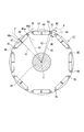
ここで、モータユニット10のロータ22の構成について図2、図3を用いて詳細に説明する。図2はロータ22の平面図であり、図3はロータ22の部分拡大図(図2のA部)である。
図2に示すように、ロータ22は、円柱状のロータコア46と、永久磁石48とを備え、出力軸(軸心)Cを中心に回転可能に支持されている。このロータコア46は、軸心Cを含む視線より見た場合に円形状の略リング状の磁性板材45が複数積層されている。さらに、開口部47がロータコア46の外周面46a近傍のヨーク部49の周方向に、例えば等間隔となるように形成されている。これら開口部47内には、それぞれ永久磁石48が保持されている。
ロータ22は永久磁石48がロータコア46に埋め込まれた、所謂IPM(Interior Permanent Magnet)モータを構成している。 Here, the configuration of therotor 22 of the motor unit 10 will be described in detail with reference to FIGS. 2 is a plan view of the rotor 22, and FIG. 3 is a partially enlarged view of the rotor 22 (A portion in FIG. 2).
As shown in FIG. 2, therotor 22 includes a cylindrical rotor core 46 and a permanent magnet 48, and is supported so as to be rotatable around an output shaft (axial center) C. The rotor core 46 is formed by laminating a plurality of circular, substantially ring-shaped magnetic plates 45 when viewed from a line of sight including the axis C. Further, the openings 47 are formed at equal intervals in the circumferential direction of the yoke portion 49 in the vicinity of the outer peripheral surface 46a of the rotor core 46, for example. A permanent magnet 48 is held in each of the openings 47.
Therotor 22 constitutes a so-called IPM (Interior Permanent Magnet) motor in which a permanent magnet 48 is embedded in a rotor core 46.
図2に示すように、ロータ22は、円柱状のロータコア46と、永久磁石48とを備え、出力軸(軸心)Cを中心に回転可能に支持されている。このロータコア46は、軸心Cを含む視線より見た場合に円形状の略リング状の磁性板材45が複数積層されている。さらに、開口部47がロータコア46の外周面46a近傍のヨーク部49の周方向に、例えば等間隔となるように形成されている。これら開口部47内には、それぞれ永久磁石48が保持されている。
ロータ22は永久磁石48がロータコア46に埋め込まれた、所謂IPM(Interior Permanent Magnet)モータを構成している。 Here, the configuration of the
As shown in FIG. 2, the
The
図3に示すように、本実施形態のロータコア46は、ロータコア46の軸心Cを含む視線より見た場合に、複数の極を構成する永久磁石48(48A,48B)がロータコア46の周方向に沿って所定の極ピッチ角α(各極間の中心線P-P´間の角度)で配置されている。
また、1つの極に配される永久磁石48が第1永久磁石48Aおよび第2永久磁石48Bとして分割配置されるように、第1永久磁石48Aが挿入される略矩形状の第1開口部47Aと、第2永久磁石48Bが挿入される略矩形状の第2開口部47Bと、これら第1開口部47Aおよび第2開口部47B間を仕切る仕切り50とが、ロータコア46の外周側の領域に形成されている。そして、各開口部47(第1開口部47A、第2開口部55B)の長手方向軸線Lが、ロータコア46の軸心Cを含む視線より見た場合に、極ピッチ角αの中心角を通る中心線C´に直交する。なお、以下の説明では、極ピッチ角αの中心線を中心線C´と定義する。 As shown in FIG. 3, therotor core 46 according to the present embodiment includes the permanent magnets 48 (48 </ b> A and 48 </ b> B) constituting a plurality of poles in the circumferential direction of the rotor core 46 when viewed from the line of sight including the axis C of the rotor core 46. Are arranged at a predetermined pole pitch angle α (angle between center lines PP ′ between the poles).
Further, a substantially rectangularfirst opening 47A into which the first permanent magnet 48A is inserted so that the permanent magnet 48 arranged on one pole is divided and arranged as a first permanent magnet 48A and a second permanent magnet 48B. And a substantially rectangular second opening 47B into which the second permanent magnet 48B is inserted, and a partition 50 partitioning the first opening 47A and the second opening 47B in the outer peripheral side region of the rotor core 46. Is formed. When the longitudinal axis L of each opening 47 (first opening 47A, second opening 55B) is viewed from the line of sight including the axis C of the rotor core 46, it passes through the central angle of the pole pitch angle α. It is orthogonal to the center line C ′. In the following description, the center line of the pole pitch angle α is defined as the center line C ′.
また、1つの極に配される永久磁石48が第1永久磁石48Aおよび第2永久磁石48Bとして分割配置されるように、第1永久磁石48Aが挿入される略矩形状の第1開口部47Aと、第2永久磁石48Bが挿入される略矩形状の第2開口部47Bと、これら第1開口部47Aおよび第2開口部47B間を仕切る仕切り50とが、ロータコア46の外周側の領域に形成されている。そして、各開口部47(第1開口部47A、第2開口部55B)の長手方向軸線Lが、ロータコア46の軸心Cを含む視線より見た場合に、極ピッチ角αの中心角を通る中心線C´に直交する。なお、以下の説明では、極ピッチ角αの中心線を中心線C´と定義する。 As shown in FIG. 3, the
Further, a substantially rectangular
以下の説明では、開口部47および永久磁石48の形状について説明するが、第一開口部47Aと第二開口部47Bの形状、および、第一永久磁石48Aと第二永久磁石48Bの形状はともに仕切り50を介して対称であるため、以下、第一開口部47Aおよび第一永久磁石48Aの形状についてのみ説明する。
In the following description, the shapes of the opening 47 and the permanent magnet 48 will be described. However, the shapes of the first opening 47A and the second opening 47B and the shapes of the first permanent magnet 48A and the second permanent magnet 48B are both the same. Since it is symmetrical via the partition 50, only the shapes of the first opening 47A and the first permanent magnet 48A will be described below.
第一開口部47Aは、第一直線部51と、第二直線部52と、第三直線部53と充填用切欠部54およびフラックスバリア55により略矩形状に構成されている。
このうち、第一直線部51は仕切り50の側面に対応する位置にあり、軸心Cを含む視線より見た場合にロータコア46の径方向に沿うように形成されている。第二直線部52は、仕切り50における軸心C側(ロータコア46の内径側)の端部から第一直線部51に対して略直角方向に延設されており、その両端には接着剤を充填するための充填用切欠部54が設けられている。第三直線部53は、仕切り50における外周面46a側の端部から第一直線部51に対して略直角方向に延設されている。そして、フラックスバリア55は、第二直線部52の端部および第三直線部53の端部から周方向外方へ膨出するように形成されている。なお、フラックスバリア55の周縁部(第一の円弧)76Aは円弧形状となるように形成されており、その曲率半径は、大きいほどフラックスバリアを形成する上で好ましい。
第一永久磁石48Aを第一開口部47Aに挿入した状態でロータコア46が回転すると、第一永久磁石48Aに遠心力がかかる。これにより、第一の円弧76Aには引張応力が働くが、第一の円弧6Aの曲率半径を大きく形成しておくことにより、特に遠心力が働きやすいフラックスバリア55の外径側における応力を、広く効果的に分散することができる。このように、遠心力による第一永久磁石48Aの引張応力を広く分散できるため、ロータコア46の破損を防止でき、所定の強度を確保することができる。 47 A of 1st opening parts are comprised by the substantially rectangular shape by the 1stlinear part 51, the 2nd linear part 52, the 3rd linear part 53, the notch part 54 for filling, and the flux barrier 55. FIG.
Among these, the 1stlinear part 51 exists in the position corresponding to the side surface of the partition 50, and when it sees from the line of sight including the axial center C, it is formed so that the radial direction of the rotor core 46 may be followed. The second straight portion 52 extends from the end of the partition 50 on the axis C side (inner diameter side of the rotor core 46) in a direction substantially perpendicular to the first straight portion 51, and both ends are filled with an adhesive. A notch 54 for filling is provided. The third straight portion 53 extends from the end on the outer peripheral surface 46 a side of the partition 50 in a direction substantially perpendicular to the first straight portion 51. The flux barrier 55 is formed so as to bulge outward from the end of the second straight part 52 and the end of the third straight part 53 in the circumferential direction. Note that the peripheral edge portion (first arc) 76A of the flux barrier 55 is formed to have an arc shape, and the larger the radius of curvature, the more preferable for forming the flux barrier.
When therotor core 46 rotates with the first permanent magnet 48A inserted into the first opening 47A, centrifugal force is applied to the first permanent magnet 48A. Thereby, tensile stress acts on the first arc 76A, but by forming a large radius of curvature of the first arc 6A, stress on the outer diameter side of the flux barrier 55 that is particularly susceptible to centrifugal force is It can be widely and effectively dispersed. Thus, since the tensile stress of the first permanent magnet 48A due to the centrifugal force can be widely dispersed, the rotor core 46 can be prevented from being damaged and a predetermined strength can be ensured.
このうち、第一直線部51は仕切り50の側面に対応する位置にあり、軸心Cを含む視線より見た場合にロータコア46の径方向に沿うように形成されている。第二直線部52は、仕切り50における軸心C側(ロータコア46の内径側)の端部から第一直線部51に対して略直角方向に延設されており、その両端には接着剤を充填するための充填用切欠部54が設けられている。第三直線部53は、仕切り50における外周面46a側の端部から第一直線部51に対して略直角方向に延設されている。そして、フラックスバリア55は、第二直線部52の端部および第三直線部53の端部から周方向外方へ膨出するように形成されている。なお、フラックスバリア55の周縁部(第一の円弧)76Aは円弧形状となるように形成されており、その曲率半径は、大きいほどフラックスバリアを形成する上で好ましい。
第一永久磁石48Aを第一開口部47Aに挿入した状態でロータコア46が回転すると、第一永久磁石48Aに遠心力がかかる。これにより、第一の円弧76Aには引張応力が働くが、第一の円弧6Aの曲率半径を大きく形成しておくことにより、特に遠心力が働きやすいフラックスバリア55の外径側における応力を、広く効果的に分散することができる。このように、遠心力による第一永久磁石48Aの引張応力を広く分散できるため、ロータコア46の破損を防止でき、所定の強度を確保することができる。 47 A of 1st opening parts are comprised by the substantially rectangular shape by the 1st
Among these, the 1st
When the
第一開口部47A内には第一永久磁石48Aが配設されている。この第一永久磁石48Aは、第一開口部47Aの第一直線部51に対応した第一直線部61と、第一開口部47Aの第二直線部52に対応した第二直線部62と、第一開口部47Aの第三直線部53に対向した第三直線部(平面部)63と、第一開口部47Aの第二直線部62の端部と第三直線部63の端部とを繋ぎ、第一直線部61と略平行に延設された第四直線部(第一開口部47Aの短手方向の側面)64と、を有している。つまり、第一永久磁石48Aは軸心Cを含む視線より見た場合に、たとえば略長方形などの矩形状に形成されている。
A first permanent magnet 48A is disposed in the first opening 47A. The first permanent magnet 48A includes a first straight portion 61 corresponding to the first straight portion 51 of the first opening 47A, a second straight portion 62 corresponding to the second straight portion 52 of the first opening 47A, The third straight part (plane part) 63 facing the third straight part 53 of the opening 47A, the end of the second straight part 62 of the first opening 47A and the end of the third straight part 63 are connected, And a fourth straight portion (side surface in the short direction of the first opening 47A) 64 that extends substantially parallel to the first straight portion 61. That is, the first permanent magnet 48A is formed in a rectangular shape such as a substantially rectangular shape when viewed from a line of sight including the axis C.
さらに、第一永久磁石48Aの径方向外側の第三直線部63に対向する第一開口部47Aの内壁側面(第三直線部53)は、その周方向の中央47A1の周辺領域が、周方向の両端部47A2に対してロータコア46の径方向外側に位置している。この中央47A1の周辺の、両端部47A2よりも径方向外側に位置している領域を逃げ溝66とする。
逃げ溝66は、第三直線部53に所定の範囲に亘って形成されている。このように第三直線部53に逃げ溝66が形成されていることにより、ロータコア46の回転時に永久磁石48に遠心力が発生しても、永久磁石48は少なくとも各両端部47A2の2箇所に当接する。このため、永久磁石48が第一開口部47Aの内壁側面の一箇所に集中して当接することがなく、ロータコア46に応力集中箇所が生じることを抑制できる。したがって、ロータコア46の強度を向上することができる。また、逃げ溝66を設ける範囲を調整することにより、永久磁石48の応力がかかる箇所を任意に設定することができる。 Further, the inner wall side surface of thefirst opening 47A facing the third straight portion 63 of the radially outer side of the first permanent magnet 48A (the third linear portion 53), the peripheral region of the center 47A 1 in the circumferential direction, the circumferential It positioned radially outwardly of the rotor core 46 with respect to the direction of both end portions 47A 2. A region around the center 47 </ b > A 1 and located radially outside the both end portions 47 </ b > A 2 is defined as a relief groove 66.
Theescape groove 66 is formed in the third linear portion 53 over a predetermined range. By the groove 66 thus escape to the third straight portion 53 is formed, even if the centrifugal force is generated in the permanent magnet 48 during rotation of the rotor core 46, two positions of the permanent magnet 48 is at least the end portions 47A 2 Abut. For this reason, the permanent magnet 48 does not concentrate and abut on one place on the side surface of the inner wall of the first opening 47 </ b> A, and it is possible to suppress the occurrence of stress concentration on the rotor core 46. Therefore, the strength of the rotor core 46 can be improved. Further, by adjusting the range in which the relief groove 66 is provided, it is possible to arbitrarily set a location where the stress of the permanent magnet 48 is applied.
逃げ溝66は、第三直線部53に所定の範囲に亘って形成されている。このように第三直線部53に逃げ溝66が形成されていることにより、ロータコア46の回転時に永久磁石48に遠心力が発生しても、永久磁石48は少なくとも各両端部47A2の2箇所に当接する。このため、永久磁石48が第一開口部47Aの内壁側面の一箇所に集中して当接することがなく、ロータコア46に応力集中箇所が生じることを抑制できる。したがって、ロータコア46の強度を向上することができる。また、逃げ溝66を設ける範囲を調整することにより、永久磁石48の応力がかかる箇所を任意に設定することができる。 Further, the inner wall side surface of the
The
また、第一永久磁石48Aの仕切り50側の第一直線部61に対向する第一開口部47Aの内壁側面(第一直線部51)に、逃げ溝67が所定の領域に亘って形成されている。逃げ溝67は、仕切り50の周方向の厚さが薄くなるように形成されている。このように逃げ溝67が形成されていることにより、ロータコア46の回転時に永久磁石48に遠心力が発生すると、永久磁石48は第一直線部51の一部の領域に当接する。このため、逃げ溝67を設ける範囲を調整することにより、永久磁石48の応力がかかる箇所を意図的に設定することができる。したがって、ロータコア46の強度を向上することができる。
Further, a relief groove 67 is formed over a predetermined region on the inner wall side surface (first straight portion 51) of the first opening 47A facing the first straight portion 61 on the partition 50 side of the first permanent magnet 48A. The escape groove 67 is formed so that the circumferential thickness of the partition 50 is reduced. By forming the escape groove 67 in this way, when a centrifugal force is generated in the permanent magnet 48 during the rotation of the rotor core 46, the permanent magnet 48 contacts a part of the first linear portion 51. For this reason, the location where the stress of the permanent magnet 48 is applied can be intentionally set by adjusting the range in which the relief groove 67 is provided. Therefore, the strength of the rotor core 46 can be improved.
また、図3に示すように、軸心Cを含む視線よりロータコア46を見た場合、ヨーク部49における外周面46aの極ピッチ角αに対応する部分は湾曲形成されている。つまり、ヨーク部49における外周面46aの軸心Cからの距離は、中心線C´とロータコア46の外周面46aとの交点46a1から外周面46aの極ピッチ角αの周方向両端部に近づくに従って短くなっている。以下、ヨーク部49の外周面46aのうち、極ピッチ角αの周方向両端部に最も近い部分を周方向両端部46a2とする。
具体的に説明すると、図2に示すように、軸心Cから交点46a1までの長さH1と、軸心Cから両端部46a2までの長さH2とを比較すると、H1>H2となっている。すなわち図3に示すように、外周面46aとステータ21の外周面(ティース部)とのギャップ(隙間)は、交点46a1から周方向両端部46a2に近づくに従って大きくなっている。 As shown in FIG. 3, when therotor core 46 is viewed from a line of sight including the axis C, a portion of the yoke portion 49 corresponding to the pole pitch angle α of the outer peripheral surface 46 a is curved. That is, the distance from the axis C of the outer peripheral surface 46a of the yoke portion 49, closer to the circumferential ends of the pole pitch angle α of the outer peripheral surface 46a from the intersection 46a 1 and the outer circumferential surface 46a of the center line C'and the rotor core 46 Shorter as you follow. Hereinafter, of the outer peripheral surface 46a of the yoke portion 49, the portion closest the circumferential ends 46a 2 in the circumferential ends of the pole pitch angle alpha.
More specifically, as shown in FIG. 2, the length H1 of the axis C to theintersection point 46a 1, when comparing the length H2 of up to both end portions 46a 2 from axis C, a H1> H2 ing. That is, as shown in FIG. 3, the outer peripheral surface of the outer peripheral surface 46a and the stator 21 gap between (teeth) (gap) is larger the closer from the intersection point 46a 1 in the circumferential ends 46a 2.
具体的に説明すると、図2に示すように、軸心Cから交点46a1までの長さH1と、軸心Cから両端部46a2までの長さH2とを比較すると、H1>H2となっている。すなわち図3に示すように、外周面46aとステータ21の外周面(ティース部)とのギャップ(隙間)は、交点46a1から周方向両端部46a2に近づくに従って大きくなっている。 As shown in FIG. 3, when the
More specifically, as shown in FIG. 2, the length H1 of the axis C to the
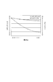
図4に、外周面46aの周方向両端部46a2とステータ21のティース部とのギャップ(隙間)の大きさと、コギングトルクおよびトルクリップルの大きさとの相関関係を解析した結果を示す。図4に示すように、周方向両端部46a2とステータ21のティース部とのギャップを大きくするに従い、コギングトルクおよびトルクリップルが低減することが分かる。つまり、軸心Cからの距離を、交点46a1から周方向両端部46a2に近づくに従って短くすることにより、ロータコア46の強度を確保しつつ、コギングトルクおよびトルクリップルを効果的に低減できる。その結果、ロータコア46が回転する際の騒音や振動の発生を抑制することができる。
Figure 4 shows the size of the gap (clearance) between the tooth portions of the circumferential ends 46a 2 and the stator 21 of the outer peripheral surface 46a, the result of analyzing the correlation between the magnitude of the cogging torque and torque ripple. As shown in FIG. 4, in accordance with increasing the gap between the tooth portions of the circumferential ends 46a 2 and the stator 21, the cogging torque and torque ripple can be seen to reduce. That is, the distance from the axis C, by shortening the closer from the intersection point 46a 1 in the circumferential ends 46a 2, while ensuring the strength of the rotor core 46 can effectively reduce the cogging torque and torque ripple. As a result, generation of noise and vibration when the rotor core 46 rotates can be suppressed.
図3に戻り、ロータコア46において隣り合う各極間の開口部47の周方向両側には、外周面46aから軸心C方向に延在する、第1溝70Aと第2溝70Bとからなる一組の溝部(補極形成溝)70が形成されている。つまり、補極形成溝70は、磁極分だけ形成されている。図3に示すように、隣接する第1溝70Aと第2溝70Bとの間に挟まれた領域が補極71として構成されている。この補極71は、磁束の通過する領域として機能する。
Returning to FIG. 3, one side formed of a first groove 70 </ b> A and a second groove 70 </ b> B extending from the outer peripheral surface 46 a in the axial center C direction on both sides in the circumferential direction of the opening 47 between adjacent poles in the rotor core 46. A set of groove portions (complementary electrode forming grooves) 70 is formed. That is, the auxiliary pole forming groove 70 is formed only for the magnetic pole. As shown in FIG. 3, a region sandwiched between the adjacent first groove 70 </ b> A and second groove 70 </ b> B is configured as an auxiliary electrode 71. The auxiliary pole 71 functions as a region through which magnetic flux passes.
溝部70(第1溝70A、第2溝70B)は、軸心Cを含む視線より見た場合に、フラックスバリア55の直近に平面視略U字状で形成されている。ここで、第一永久磁石48Aの近傍に形成された溝部を第1溝70Aとし、第二永久磁石48Bの近傍に形成された溝部を第2溝70Bとする。つまり、ロータコア46における第1溝70Aと第2溝70Bとの間に挟まれた領域が補極71となっている。
The groove part 70 (the first groove 70A and the second groove 70B) is formed in a substantially U shape in plan view in the immediate vicinity of the flux barrier 55 when viewed from the line of sight including the axis C. Here, the groove formed near the first permanent magnet 48A is referred to as a first groove 70A, and the groove formed near the second permanent magnet 48B is referred to as a second groove 70B. That is, the region sandwiched between the first groove 70 </ b> A and the second groove 70 </ b> B in the rotor core 46 is the auxiliary pole 71.
補極71の外周縁71aの周方向両側には、周方向両側へ突出した凸部72がそれぞれ形成されている。この補極71の周方向の厚みは、径方向内側の領域の厚みW1よりも、外周縁71aの領域の厚みW2の方が厚く形成されている。この凸部72の形状としては、軸心Cを含む視線より見た場合に略矩形状の形状であることが望ましい。凸部72が略矩形状で形成されていることにより、溝部70の周方向の幅を確保しつつ、凸部72の面積をできる限り大きく確保することができる。
また、補極71における外周面71bから軸心Cまでの長さは、補極71の周方向に沿って略同一になっている。つまり、補極71の外周面71bとステータ21のティース部とのギャップ(隙間)は、全長に亘って略同一になっている。Convex portions 72 protruding to both sides in the circumferential direction are formed on both sides in the circumferential direction of the outer peripheral edge 71a of the auxiliary pole 71, respectively. As for the thickness in the circumferential direction of the auxiliary pole 71, the thickness W2 in the region of the outer peripheral edge 71a is formed thicker than the thickness W1 in the region on the radially inner side. The shape of the convex portion 72 is desirably a substantially rectangular shape when viewed from a line of sight including the axis C. By forming the convex portion 72 in a substantially rectangular shape, the area of the convex portion 72 can be ensured as large as possible while ensuring the circumferential width of the groove portion 70.
Further, the length from the outerperipheral surface 71 b to the axis C in the auxiliary pole 71 is substantially the same along the circumferential direction of the auxiliary pole 71. That is, the gap (gap) between the outer peripheral surface 71b of the auxiliary pole 71 and the teeth portion of the stator 21 is substantially the same over the entire length.
また、補極71における外周面71bから軸心Cまでの長さは、補極71の周方向に沿って略同一になっている。つまり、補極71の外周面71bとステータ21のティース部とのギャップ(隙間)は、全長に亘って略同一になっている。
Further, the length from the outer
さらに、溝部70の内周面70aは湾曲形成されており、中心線C´から補極71が配された側に近づくに従って、内周面70aと軸心Cとの距離が徐々に短くなっている。溝部70の内周面70aをこのように湾曲形成することにより、補極71の周方向の幅を大きく確保することができる。このため、モータ23としてのトルク向上やロータコア46の強度向上を図ることができる。なお、内周面70aを上述したように湾曲形成した場合と、U字状になるように形成した場合とでは、ロータ22の回転により永久磁石48の遠心力が発生した場合であっても、その応力分布は変わらない。つまり、内周面70aの形状がいずれの場合であっても、内周面70aの中心線C´側には応力が生じるが、補極71側には応力が生じない。したがって、溝部70の内周面70aと軸心Cとの距離を、中心線C´から補極71が配された側に近づくに従って徐々に短くなるように湾曲形成することにより、溝部70の周方向の幅を小さくすることができる。
Further, the inner peripheral surface 70a of the groove portion 70 is curved, and the distance between the inner peripheral surface 70a and the shaft center C gradually decreases as the distance from the center line C ′ to the side where the auxiliary pole 71 is disposed. Yes. By forming the inner peripheral surface 70a of the groove portion 70 in this way, a large width in the circumferential direction of the auxiliary pole 71 can be secured. For this reason, the torque improvement as the motor 23 and the strength improvement of the rotor core 46 can be achieved. In addition, even when the centrifugal force of the permanent magnet 48 is generated by the rotation of the rotor 22 between the case where the inner peripheral surface 70a is curved as described above and the case where the inner peripheral surface 70a is formed in a U shape, The stress distribution does not change. That is, regardless of the shape of the inner peripheral surface 70a, stress is generated on the center line C ′ side of the inner peripheral surface 70a, but no stress is generated on the complementary electrode 71 side. Accordingly, by curving the distance between the inner peripheral surface 70a of the groove portion 70 and the axis C so as to gradually decrease from the center line C ′ toward the side where the auxiliary pole 71 is disposed, The width in the direction can be reduced.
ロータコア46のヨーク部49には、開口部47(第一開口部47A、第二開口部47B)と溝部70(第1溝70Aおよび第2溝70B)との間にそれぞれリブ75(リブ75Aおよびリブ75B)が形成されている。リブ75A、75Bは、それぞれ永久磁石48を介して対称に形成されている。よって、リブ75の構成について、リブ75Aを例に、図5を用いて以下説明する。
The yoke portion 49 of the rotor core 46 has ribs 75 ( ribs 75A and 75B) between the opening 47 (first opening 47A and second opening 47B) and the groove 70 (first groove 70A and second groove 70B), respectively. Ribs 75B) are formed. The ribs 75A and 75B are formed symmetrically via the permanent magnet 48, respectively. Therefore, the configuration of the rib 75 will be described below with reference to FIG. 5 taking the rib 75A as an example.
リブ75Aの周方向の側面のうち、第一永久磁石48Aの側面の直線部分を第1リブ側面76とし、補極71側の側面の直線部分を第2リブ側面77とする。第1リブ側面76と第2リブ側面77は、平行となるように設けられている。また、第1リブ側面76および第2リブ側面77は、軸心Cを含む視線より見た場合に、第四直線部64に対して-45°~+45°の角度で傾斜するように形成されている。本実施形態においては、第1リブ側面76および第2リブ側面77が第四直線部64に対して約+30°の角度で傾斜するように形成された例について説明する。
Among the side surfaces of the rib 75A in the circumferential direction, the straight portion of the side surface of the first permanent magnet 48A is defined as a first rib side surface 76, and the straight portion of the side surface on the auxiliary pole 71 side is defined as a second rib side surface 77. The 1st rib side surface 76 and the 2nd rib side surface 77 are provided so that it may become parallel. Further, the first rib side surface 76 and the second rib side surface 77 are formed so as to be inclined at an angle of −45 ° to + 45 ° with respect to the fourth straight portion 64 when viewed from the line of sight including the axis C. ing. In the present embodiment, an example will be described in which the first rib side surface 76 and the second rib side surface 77 are formed to be inclined at an angle of about + 30 ° with respect to the fourth linear portion 64.
ここで、図5に示すように、第1リブ側面76に沿う線分を第1リブ側面形成線78とし、第2リブ側面77に沿う線分を第2リブ側面形成線79とする。そして、第1リブ側面形成線78および第2リブ側面形成線79と平行であって、かつ、第一永久磁石48Aの外周側角部58を通過する線分を第1平行線80とし、第1リブ側面形成線78および第2リブ側面形成線79と平行であって溝部70の最深部(溝部70の内周のうち、最も内径側の箇所)89を通過する線分を第2平行線81とする。なお、本実施形態では、第2平行線81は、補極71の側面73と一致する線分となっている。
Here, as shown in FIG. 5, a line segment along the first rib side surface 76 is defined as a first rib side surface formation line 78, and a line segment along the second rib side surface 77 is defined as a second rib side surface formation line 79. A line segment that is parallel to the first rib side surface forming line 78 and the second rib side surface forming line 79 and that passes through the outer peripheral side corner 58 of the first permanent magnet 48A is defined as a first parallel line 80. A line segment that is parallel to the first rib side surface forming line 78 and the second rib side surface forming line 79 and passes through the deepest portion (the innermost side portion of the inner periphery of the groove portion 70) 89 is a second parallel line. 81. In the present embodiment, the second parallel line 81 is a line segment that coincides with the side surface 73 of the auxiliary pole 71.
また、第1リブ側面76は、円弧状の第一の円弧76Aに繋がっている。第1リブ側面76は第1リブ側面形成線78と重なっており、その領域の軸心C側の端部を第1始点82、外周面46a側の端部を第1終点83とする。
また、第2リブ側面77は、円弧状の第二の円弧77Aに繋がっている。第2リブ側面77は第2リブ側面形成線79と重なっており、その領域の軸心C側の端部を第2始点85、外周面46a側の端部を第2終点86とする。 The firstrib side surface 76 is connected to the arc-shaped first arc 76A. The first rib side surface 76 overlaps the first rib side surface forming line 78, and the end portion on the axis C side of the region is the first start point 82 and the end portion on the outer peripheral surface 46 a side is the first end point 83.
The secondrib side surface 77 is connected to an arcuate second arc 77A. The second rib side surface 77 overlaps the second rib side surface forming line 79, and the end on the axis C side of the region is the second start point 85 and the end on the outer peripheral surface 46 a side is the second end point 86.
また、第2リブ側面77は、円弧状の第二の円弧77Aに繋がっている。第2リブ側面77は第2リブ側面形成線79と重なっており、その領域の軸心C側の端部を第2始点85、外周面46a側の端部を第2終点86とする。 The first
The second
本実施形態では、第1リブ側面形成線78と直交し、かつ、第1始点82を通過する線分を第1垂線88とした場合に、第2始点85は、第1垂線88よりも外周面46a側に位置している。また、補極71の側面73の最深部89は、第1垂線88よりも外周面46a側に位置し、かつ、第2始点85よりも軸心C側に位置している。
さらに、第2リブ側面形成線79と直交し、かつ、第2終点86を通過する線分を第2垂線90とした場合、第1終点83は、第2垂線90よりも軸心C側に位置している。そして、第一永久磁石48Aの外周側角部58は、第2垂線90より軸心C側で、かつ、第1終点83よりも外周面46a側に位置している。 In the present embodiment, when the line perpendicular to the first rib sidesurface forming line 78 and passing through the first start point 82 is a first perpendicular 88, the second start point 85 is more peripheral than the first perpendicular 88. It is located on the surface 46a side. Further, the deepest portion 89 of the side surface 73 of the auxiliary pole 71 is located on the outer peripheral surface 46 a side with respect to the first perpendicular 88 and is located on the axis C side with respect to the second starting point 85.
Furthermore, when the line perpendicular to the second rib sidesurface forming line 79 and passing through the second end point 86 is the second perpendicular line 90, the first end point 83 is closer to the axis C side than the second perpendicular line 90. positioned. The outer peripheral side corner 58 of the first permanent magnet 48 </ b> A is located closer to the axis C side than the second perpendicular 90 and closer to the outer peripheral surface 46 a than the first end point 83.
さらに、第2リブ側面形成線79と直交し、かつ、第2終点86を通過する線分を第2垂線90とした場合、第1終点83は、第2垂線90よりも軸心C側に位置している。そして、第一永久磁石48Aの外周側角部58は、第2垂線90より軸心C側で、かつ、第1終点83よりも外周面46a側に位置している。 In the present embodiment, when the line perpendicular to the first rib side
Furthermore, when the line perpendicular to the second rib side
本実施形態では、第1終点83と、第一永久磁石48Aの外周側角部58との間は、例えば円弧状の第一の円弧76Aにより繋がっている。また、第2始点85と、最深部89との間も例えば円弧状の第二の円弧77Aにより繋がっている。なお、第一の円弧76Aおよび第二の円弧77Aの形状は円弧状に限られず、直線状であっても構わない。
In the present embodiment, the first end point 83 and the outer peripheral side corner 58 of the first permanent magnet 48A are connected by, for example, a first arc 76A having an arc shape. Further, the second starting point 85 and the deepest portion 89 are also connected by, for example, an arc-shaped second arc 77A. The shapes of the first arc 76A and the second arc 77A are not limited to arcs, and may be linear.
ロータ22の軸心Cを含む断面の断面視において、ヨーク部49の中で最も厚さの薄い薄肉部からなる応力吸収部94がリブ75に形成されている。第1垂線88と平行で、かつ、第1リブ側面76および第2リブ側面77と交差する線分をそれぞれ第3垂線91、第4垂線92とすると、応力吸収部94は、第1リブ側面76と、第2リブ側面77と、第3垂線91および第4垂線92に囲まれた領域となる。
In the cross-sectional view of the cross section including the axis C of the rotor 22, a stress absorbing portion 94 composed of the thinnest portion of the yoke portion 49 is formed in the rib 75. When the line segments that are parallel to the first perpendicular line 88 and intersect the first rib side face 76 and the second rib side face 77 are the third perpendicular line 91 and the fourth perpendicular line 92, respectively, the stress absorbing portion 94 has the first rib side face. 76, the second rib side surface 77, and the region surrounded by the third perpendicular line 91 and the fourth perpendicular line 92.
また、第二の円弧77Aと外周面71bとの距離D1は、隣り合う各極間の短絡磁束を低減可能な深さで形成されている。具体的には図2に示すように、軸心Cと最深部89とを結んだ距離X1が、その最深部89に近接する永久磁石48の外周側角部58と軸心Cとの距離X2よりも短くなっている。つまり、最深部89の位置は、溝部70と永久磁石48とが周方向にラップするように設定されている。
Further, the distance D1 between the second arc 77A and the outer peripheral surface 71b is formed to a depth that can reduce the short-circuit magnetic flux between adjacent poles. Specifically, as shown in FIG. 2, the distance X1 connecting the axis C and the deepest part 89 is the distance X2 between the outer peripheral side corner 58 of the permanent magnet 48 and the axis C close to the deepest part 89. Is shorter. That is, the position of the deepest portion 89 is set so that the groove portion 70 and the permanent magnet 48 wrap in the circumferential direction.
なお、溝部70の周方向の幅は、特に限定する必要はないが、ロータコア46の強度が確保される程度の長さにすることが望ましい。また、溝部70の形成位置は、できる限り、その溝部70に近接する永久磁石48に近い位置とすることがモータ23の性能にとっては好ましい。しかし、図5に示されるように、溝部70の形成位置が永久磁石48に近いほど、応力吸収部94の周方向の幅W3は小さくなる。このため、ロータコア46の強度を考慮して、応力吸収部94の周方向の幅W3と溝部70の形成位置とを設定することが必要である。また、ロータコア46における応力吸収部94は、最も磁束が飽和する箇所になるが、応力吸収部94の一方側にフラックスバリア55が形成されるとともに、他方側に溝部70が形成されることにより、磁束短絡の発生を防ぐことができる。
The width in the circumferential direction of the groove part 70 is not particularly limited, but it is desirable to make the length sufficient to ensure the strength of the rotor core 46. In addition, it is preferable for the performance of the motor 23 that the groove 70 is formed as close as possible to the permanent magnet 48 close to the groove 70. However, as shown in FIG. 5, the closer the groove 70 is formed to the permanent magnet 48, the smaller the circumferential width W <b> 3 of the stress absorbing portion 94. For this reason, in consideration of the strength of the rotor core 46, it is necessary to set the circumferential width W3 of the stress absorbing portion 94 and the formation position of the groove portion 70. Further, the stress absorbing portion 94 in the rotor core 46 is a portion where the magnetic flux is most saturated, but the flux barrier 55 is formed on one side of the stress absorbing portion 94 and the groove portion 70 is formed on the other side. Generation | occurrence | production of a magnetic flux short circuit can be prevented.
本実施形態によれば、開口部47に永久磁石48が挿入された状態でロータコア46が軸心C回りに回転すると、永久磁石48に遠心力が発生する。この際、リブ75(75A、75B)に、ロータ22の軸心Cを含む断面の断面視においてヨーク部49の中で最も厚さの薄い薄肉部からなる応力吸収部94が設けられていることにより、永久磁石48に起因してロータ22に発生する応力がこの応力吸収部94に集中する。このため、ロータ22に発生する応力を応力吸収部94で吸収することができる。この結果、リブ75の付け根に応力が集中することを抑制できる。このため、リブ75の付け根部分の厚さを確保する必要がなくなり、ロータコア46の設計自由度を向上させることができるとともに、ロータ22の軽量化を実現できる。
According to this embodiment, when the rotor core 46 rotates around the axis C with the permanent magnet 48 inserted in the opening 47, centrifugal force is generated in the permanent magnet 48. At this time, the rib 75 (75A, 75B) is provided with a stress absorbing portion 94 that is the thinnest portion of the yoke portion 49 in the cross-sectional view of the cross section including the axis C of the rotor 22. As a result, the stress generated in the rotor 22 due to the permanent magnet 48 concentrates on the stress absorbing portion 94. For this reason, the stress generated in the rotor 22 can be absorbed by the stress absorbing portion 94. As a result, it is possible to suppress stress concentration at the base of the rib 75. For this reason, it is not necessary to ensure the thickness of the base portion of the rib 75, the degree of freedom in designing the rotor core 46 can be improved, and the weight of the rotor 22 can be reduced.
また、開口部47の長手方向軸線Lが、ロータコア46の軸心Cを含む視線より見た場合に中心線C´に直交するように形成されているため、ロータコア46の回転による永久磁石48の応力をリブ75に集中させることができる。
また、リブ75の周方向の側面に、第1リブ側面76と、この第1リブ側面76へ繋がる第一の円弧76Aと、第2リブ側面77と、この第2リブ側面77から補極71へ繋がる第二の円弧77Aと、が設けられているため、リブ75に集中する応力が第1リブ側面76と第2リブ側面77との間に設けられた応力吸収部94に効率よく吸収させることができる。また、ロータコア46の回転によりフラックスバリア55の周縁部に働く引張応力を、第一の円弧76Aにおいて広く効果的に分散できる。このため、引張応力によるロータコア46の破損を防止でき、所定の強度を確保することができる。 Further, since the longitudinal axis L of theopening 47 is formed so as to be orthogonal to the center line C ′ when viewed from the line of sight including the axis C of the rotor core 46, the permanent magnet 48 of the rotor core 46 rotates. The stress can be concentrated on the rib 75.
Further, on the side surface in the circumferential direction of therib 75, the first rib side surface 76, the first arc 76 </ b> A connected to the first rib side surface 76, the second rib side surface 77, and the second electrode 71 from the second rib side surface 77. Since the second arc 77A connected to the second rib side surface 77 is provided, stress concentrated on the rib 75 is efficiently absorbed by the stress absorbing portion 94 provided between the first rib side surface 76 and the second rib side surface 77. be able to. Further, the tensile stress acting on the peripheral portion of the flux barrier 55 by the rotation of the rotor core 46 can be widely and effectively distributed in the first arc 76A. For this reason, damage to the rotor core 46 due to tensile stress can be prevented, and a predetermined strength can be ensured.
また、リブ75の周方向の側面に、第1リブ側面76と、この第1リブ側面76へ繋がる第一の円弧76Aと、第2リブ側面77と、この第2リブ側面77から補極71へ繋がる第二の円弧77Aと、が設けられているため、リブ75に集中する応力が第1リブ側面76と第2リブ側面77との間に設けられた応力吸収部94に効率よく吸収させることができる。また、ロータコア46の回転によりフラックスバリア55の周縁部に働く引張応力を、第一の円弧76Aにおいて広く効果的に分散できる。このため、引張応力によるロータコア46の破損を防止でき、所定の強度を確保することができる。 Further, since the longitudinal axis L of the
Further, on the side surface in the circumferential direction of the
また、軸心Cからの距離が、中心線C´とロータコア46の外周面46aとの交点46a1から外周面46aの極ピッチ角αの周方向両端部46a2に近づくに従って短くなるため、ロータコア46の外周面46aとステータ21のティース部(外周面)との間の距離が周方向両端部46a2に近づくほど大きくなる。これにより、ロータコア46の回転によるトルクリップルおよびコギングトルクを低減することができる。その結果、ロータコア46が回転する際のモータ駆動時に振動や騒音が生じることを抑制できる。
また、ロータコア46の回転による応力が応力吸収部94で吸収されることでリブ75が伸張しても、周方向両端部46a2において、ロータコア46の外周面46aとステータ21の外周面との間に距離があるため、この箇所がロータ22の最外周面46a側より径方向外側へ突出しにくい。このため、ステータ21とロータ22の干渉を確実に防止できる。また、ステータ21とロータ22との間の隙間(ギャップ)をより小さくすることができる。 Further, since the distance from the axis C is shorter toward the circumferential ends 46a 2 of the pole pitch angle α of the outerperipheral surface 46a from the intersection 46a 1 and the outer circumferential surface 46a of the center line C'and the rotor core 46, rotor core as the distance between the tooth portions of the outer peripheral surface 46a and the stator 21 of 46 (outer peripheral surface) approaches circumferential ends 46a 2 increases. Thereby, torque ripple and cogging torque due to rotation of the rotor core 46 can be reduced. As a result, it is possible to suppress the occurrence of vibration and noise when the motor is driven when the rotor core 46 rotates.
Further, even if therib 75 is expanded by absorbing the stress caused by the rotation of the rotor core 46 by the stress absorbing portion 94, the outer circumferential surface 46 a of the rotor core 46 and the outer circumferential surface of the stator 21 are located at both circumferential ends 46 a 2 . Because of this distance, it is difficult for this portion to protrude radially outward from the outermost peripheral surface 46 a side of the rotor 22. For this reason, the interference between the stator 21 and the rotor 22 can be reliably prevented. Further, the gap (gap) between the stator 21 and the rotor 22 can be further reduced.
また、ロータコア46の回転による応力が応力吸収部94で吸収されることでリブ75が伸張しても、周方向両端部46a2において、ロータコア46の外周面46aとステータ21の外周面との間に距離があるため、この箇所がロータ22の最外周面46a側より径方向外側へ突出しにくい。このため、ステータ21とロータ22の干渉を確実に防止できる。また、ステータ21とロータ22との間の隙間(ギャップ)をより小さくすることができる。 Further, since the distance from the axis C is shorter toward the circumferential ends 46a 2 of the pole pitch angle α of the outer
Further, even if the
さらに、開口部47に逃げ溝66が形成されていることにより、ロータコア46の回転時に永久磁石48に遠心力が発生しても、永久磁石48は少なくとも各両端部47A2の2箇所に当接する。このため、永久磁石48が第一開口部47Aの内壁側面の一箇所に集中して当接することがなく、ロータコア46に応力集中箇所が発生することを抑制できる。また、逃げ溝66を設ける範囲を調整することにより、永久磁石48の応力がかかる箇所を意図的に設定することができる。したがって、ロータコア46の強度を向上することができる。
Furthermore, by the groove 66 escapes to the opening 47 is formed, even if the centrifugal force is generated in the permanent magnet 48 during rotation of the rotor core 46, permanent magnets 48 abuts at least at two places of each end portions 47A 2 . For this reason, the permanent magnet 48 does not concentrate and come into contact with one place on the side surface of the inner wall of the first opening 47A, and it is possible to suppress the occurrence of a stress concentration place on the rotor core 46. Further, by adjusting the range in which the relief groove 66 is provided, it is possible to intentionally set a location where the stress of the permanent magnet 48 is applied. Therefore, the strength of the rotor core 46 can be improved.
そして、上記のように構成されたロータ22を有したモータ23を採用することにより、リラクタンストルクを発生させつつ、トルクリップルを低減することができる。以上により、トルクを上昇させることができるモータ23を提供することができる。
Further, by adopting the motor 23 having the rotor 22 configured as described above, it is possible to reduce torque ripple while generating reluctance torque. As described above, the motor 23 capable of increasing the torque can be provided.
尚、本発明は上述した実施形態のみに限られるものではなく、本発明の趣旨を逸脱しない範囲において、上述した実施形態に種々の変更を加えたものを含む。すなわち、実施形態で挙げた具体的な構造や形状などはほんの一例に過ぎず、適宜変更が可能である。
例えば、本実施形態においては、ロータコア46に仕切り50を設けて永久磁石48を2分割にし、第一永久磁石48Aと第二永久磁石48Bとして配した場合の説明をしたが、永久磁石48は分割しない構成であってもよい。
また、本実施形態においては、接着剤を充填するための充填用切欠部54が開口部47に形成されているが、他の手段により開口部47内に永久磁石48を固定できる場合には充填用切欠部54は形成されていなくても構わない。
また、本実施形態においては、開口部47と永久磁石48との隙間に接着剤を充填することで永久磁石48を固定する場合について説明したが、永久磁石48を開口部47内に保持可能であれば、どのような充填剤を用いても構わない。 Note that the present invention is not limited to the above-described embodiments, and includes those in which various modifications are made to the above-described embodiments without departing from the spirit of the present invention. That is, the specific structure and shape described in the embodiment are merely examples, and can be changed as appropriate.
For example, in the present embodiment, the description has been given of the case where therotor core 46 is provided with the partition 50 to divide the permanent magnet 48 into two parts and are arranged as the first permanent magnet 48A and the second permanent magnet 48B. The structure which does not do may be sufficient.
In this embodiment, the fillingnotch 54 for filling the adhesive is formed in the opening 47. However, when the permanent magnet 48 can be fixed in the opening 47 by other means, the filling is made. The cutout 54 may not be formed.
In the present embodiment, the case where thepermanent magnet 48 is fixed by filling the gap between the opening 47 and the permanent magnet 48 with an adhesive has been described. However, the permanent magnet 48 can be held in the opening 47. Any filler may be used as long as it is present.
例えば、本実施形態においては、ロータコア46に仕切り50を設けて永久磁石48を2分割にし、第一永久磁石48Aと第二永久磁石48Bとして配した場合の説明をしたが、永久磁石48は分割しない構成であってもよい。
また、本実施形態においては、接着剤を充填するための充填用切欠部54が開口部47に形成されているが、他の手段により開口部47内に永久磁石48を固定できる場合には充填用切欠部54は形成されていなくても構わない。
また、本実施形態においては、開口部47と永久磁石48との隙間に接着剤を充填することで永久磁石48を固定する場合について説明したが、永久磁石48を開口部47内に保持可能であれば、どのような充填剤を用いても構わない。 Note that the present invention is not limited to the above-described embodiments, and includes those in which various modifications are made to the above-described embodiments without departing from the spirit of the present invention. That is, the specific structure and shape described in the embodiment are merely examples, and can be changed as appropriate.
For example, in the present embodiment, the description has been given of the case where the
In this embodiment, the filling
In the present embodiment, the case where the
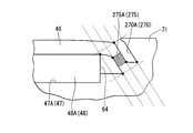
さらに、本実施形態においては、第1リブ側面76および第2リブ側面77が軸心Cを含む視線より見た場合に、第四直線部64に対して約+30°の角度で傾斜するように形成された例について説明をしたが、図6に示すように、リブ175Aの周方向の側面が第四直線部64に対して略平行(第四直線部64に対して約0°の角度)となるように形成されてもよい。
また、図7に示すように、リブ275Aの周方向の側面が第四直線部64に対して約-30°の角度で傾斜するように形成されていてもよい。つまり、第1リブの周方向の側面は、第四直線部64に対して-45°~+45°の角度で傾斜するように形成されていればよい。 Furthermore, in the present embodiment, the firstrib side surface 76 and the second rib side surface 77 are inclined at an angle of about + 30 ° with respect to the fourth straight portion 64 when viewed from the line of sight including the axis C. Although the formed example has been described, as shown in FIG. 6, the side surface in the circumferential direction of the rib 175 </ b> A is substantially parallel to the fourth straight portion 64 (an angle of about 0 ° with respect to the fourth straight portion 64). May be formed.
Further, as shown in FIG. 7, the side surface in the circumferential direction of therib 275A may be formed so as to be inclined at an angle of about −30 ° with respect to the fourth linear portion 64. That is, the circumferential side surface of the first rib may be formed so as to be inclined at an angle of −45 ° to + 45 ° with respect to the fourth straight portion 64.
また、図7に示すように、リブ275Aの周方向の側面が第四直線部64に対して約-30°の角度で傾斜するように形成されていてもよい。つまり、第1リブの周方向の側面は、第四直線部64に対して-45°~+45°の角度で傾斜するように形成されていればよい。 Furthermore, in the present embodiment, the first
Further, as shown in FIG. 7, the side surface in the circumferential direction of the
本発明によれば、リブの付け根の応力集中を抑制可能なロータおよびモータを提供することができる。
According to the present invention, it is possible to provide a rotor and a motor that can suppress stress concentration at the base of the rib.
20 コイル(巻線)
21 ステータ
22 ロータ
23 モータ
46 ロータコア
46a 外周面
46a1 交点
46a2 両端部
47(47A,47B) 開口部
47A1 中央
47A2 両端部
48(48A,48B) 永久磁石
49 ヨーク部
50 仕切り
58 外周側角部
63 第三直線部(平面部)
64 第四直線部(短手方向の側面)
66 逃げ溝
70 溝部(一対の補極形成溝)
70a 内周面
70A 第1溝
70B 第2溝
71 補極
73 補極の側面
75(75A,75B) リブ
76 第1リブ側面
76A 第一の円弧
77 第2リブ側面
77A 第二の円弧
78 第1リブ側面形成線
79 第2リブ側面形成線
80 第1平行線
81 第2平行線
82 第1始点
83 第1終点
85 第2始点
86 第2終点
88 第1垂線
89 最深部(最も内径側の箇所)
90 第2垂線
91 第3垂線
92 第4垂線
94 応力吸収部(薄肉部)
C 軸心
C´ 中心線
α 極ピッチ角
H1 軸心から交点までの長さ
H2 軸心から両端部までの長さ 20 Coil (winding)
21Stator 22 Rotor 23 Motor 46 Rotor Core 46a Peripheral Surface 46a 1 Intersection 46a 2 Both Ends 47 (47A, 47B) Opening 47A 1 Center 47A 2 Both Ends 48 (48A, 48B) Permanent Magnet 49 York Part 50 Partition 58 Peripheral Side Angle Part 63 Third straight part (plane part)
64 Fourth straight section (side surface in short direction)
66Escape groove 70 Groove part (a pair of auxiliary pole forming grooves)
70a Innerperipheral surface 70A 1st groove 70B 2nd groove 71 Supplement pole 73 Side surface 75 of supplementary pole 75 (75A, 75B) Rib 76 1st rib side surface 76A 1st circular arc 77 2nd rib side surface 77A 2nd circular arc 78 1st Rib side surface forming line 79 2nd rib side surface forming line 80 1st parallel line 81 2nd parallel line 82 1st start point 83 1st end point 85 2nd start point 86 2nd end point 88 1st perpendicular line 89 The deepest part (location on the innermost diameter side) )
90 Secondperpendicular line 91 Third perpendicular line 92 Fourth perpendicular line 94 Stress absorbing part (thin part)
C axis C 'center line α pole pitch angle H1 length from axis to intersection H2 length from axis to both ends
21 ステータ
22 ロータ
23 モータ
46 ロータコア
46a 外周面
46a1 交点
46a2 両端部
47(47A,47B) 開口部
47A1 中央
47A2 両端部
48(48A,48B) 永久磁石
49 ヨーク部
50 仕切り
58 外周側角部
63 第三直線部(平面部)
64 第四直線部(短手方向の側面)
66 逃げ溝
70 溝部(一対の補極形成溝)
70a 内周面
70A 第1溝
70B 第2溝
71 補極
73 補極の側面
75(75A,75B) リブ
76 第1リブ側面
76A 第一の円弧
77 第2リブ側面
77A 第二の円弧
78 第1リブ側面形成線
79 第2リブ側面形成線
80 第1平行線
81 第2平行線
82 第1始点
83 第1終点
85 第2始点
86 第2終点
88 第1垂線
89 最深部(最も内径側の箇所)
90 第2垂線
91 第3垂線
92 第4垂線
94 応力吸収部(薄肉部)
C 軸心
C´ 中心線
α 極ピッチ角
H1 軸心から交点までの長さ
H2 軸心から両端部までの長さ 20 Coil (winding)
21
64 Fourth straight section (side surface in short direction)
66
70a Inner
90 Second
C axis C 'center line α pole pitch angle H1 length from axis to intersection H2 length from axis to both ends
Claims (5)
- 円柱状のロータコアと、このロータコアの軸心を含む視線より見た場合に前記ロータコアの周方向に沿って所定の極ピッチ角に並んで配置された永久磁石と、を備えたロータであって、
前記ロータコアは、
前記ロータコアの外周面に形成された、前記永久磁石が挿入される開口部と、
前記開口部の周方向両側にそれぞれ前記軸心方向に延在する一対の第1溝及び第2溝からなる、磁極数分だけ形成された補極形成溝と、
前記第1溝とこの第1溝に隣り合う前記第2溝との間に形成された補極と、
前記ロータコアのヨーク部の、前記開口部と前記補極形成溝との間に形成されたリブと、
を有し;
前記リブに、前記ロータの軸心を含む断面の断面視において前記ヨーク部の中で最も厚さの薄い薄肉部からなる応力吸収部が形成されている;
ことを特徴とするロータ。 A rotor comprising: a cylindrical rotor core; and permanent magnets arranged in a predetermined pole pitch angle along the circumferential direction of the rotor core when viewed from a line of sight including the axis of the rotor core,
The rotor core is
An opening formed in the outer peripheral surface of the rotor core and into which the permanent magnet is inserted;
A pair of first and second grooves extending in the axial direction on both sides in the circumferential direction of the opening, and complementary pole forming grooves formed by the number of magnetic poles;
An auxiliary pole formed between the first groove and the second groove adjacent to the first groove;
A rib formed between the opening of the yoke portion of the rotor core and the complementary electrode forming groove;
Having
The rib is formed with a stress absorbing portion made of a thin portion having the thinnest thickness among the yoke portions in a cross-sectional view of a cross section including the axis of the rotor;
A rotor characterized by that. - 前記開口部の長手方向軸線が、前記ロータコアの前記軸心を含む視線より見た場合に前記極ピッチ角の中心角を通る中心線に直交するように形成され;
前記リブの側面は、前記永久磁石側の第1リブ側面と、この第1リブ側面から前記開口部へ繋がる第一の円弧と、前記補極側の第2リブ側面と、この第2リブ側面から前記補極へ繋がる第二の円弧と、を有し;
前記応力吸収部は、前記第1リブ側面と前記第2リブ側面との間に設けられている;
ことを特徴とする請求項1に記載のロータ。 A longitudinal axis of the opening is formed to be orthogonal to a center line passing through a central angle of the pole pitch angle when viewed from a line of sight including the axis of the rotor core;
The side surface of the rib includes a first rib side surface on the permanent magnet side, a first arc connected from the first rib side surface to the opening, a second rib side surface on the complementary pole side, and a second rib side surface. And a second arc connected to the complementary pole;
The stress absorbing portion is provided between the first rib side surface and the second rib side surface;
The rotor according to claim 1. - 前記ロータコアの前記軸心を含む視線より見た場合に、前記ヨーク部における前記軸心からの距離が、前記極ピッチ角の中心角を通る中心線と前記ロータコアの外周面との交点から前記極ピッチ角の周方向両端部に近づくに従って短くなることを特徴とする請求項1に記載のロータ。 When viewed from the line of sight including the axis of the rotor core, the distance from the axis of the yoke portion is determined from the intersection of the center line passing through the central angle of the pole pitch angle and the outer peripheral surface of the rotor core. The rotor according to claim 1, wherein the rotor becomes shorter as it approaches both ends in the circumferential direction of the pitch angle.
- 前記永久磁石の径方向外側の平面部に対向する前記開口部の内壁側面の周方向の中央が、前記内壁側面の周方向の両端部に対して前記ロータコアの径方向外側に位置していることを特徴とする請求項1に記載のロータ。 The center in the circumferential direction of the inner wall side surface of the opening facing the flat portion on the radially outer side of the permanent magnet is located on the outer side in the radial direction of the rotor core with respect to both ends in the circumferential direction of the inner wall side surface. The rotor according to claim 1.
- 請求項1~4のいずれか1項に記載のロータと;
前記ロータを囲繞する円筒状のステータと;
前記ステータのティース部に巻回された巻線と;
を有することを特徴とするモータ。 A rotor according to any one of claims 1 to 4;
A cylindrical stator surrounding the rotor;
A winding wound around a tooth portion of the stator;
The motor characterized by having.
Priority Applications (4)
| Application Number | Priority Date | Filing Date | Title |
|---|---|---|---|
| JP2012526490A JPWO2012014836A1 (en) | 2010-07-30 | 2011-07-25 | Rotor and motor |
| US13/812,821 US20130119812A1 (en) | 2010-07-30 | 2011-07-25 | Rotor and motor |
| CN2011800362346A CN103004057A (en) | 2010-07-30 | 2011-07-25 | Rotor and motor |
| EP11812426.2A EP2600496A4 (en) | 2010-07-30 | 2011-07-25 | Rotor and motor |
Applications Claiming Priority (2)
| Application Number | Priority Date | Filing Date | Title |
|---|---|---|---|
| JP2010-172260 | 2010-07-30 | ||
| JP2010172260 | 2010-07-30 |
Publications (1)
| Publication Number | Publication Date |
|---|---|
| WO2012014836A1 true WO2012014836A1 (en) | 2012-02-02 |
Family
ID=45530044
Family Applications (1)
| Application Number | Title | Priority Date | Filing Date |
|---|---|---|---|
| PCT/JP2011/066832 WO2012014836A1 (en) | 2010-07-30 | 2011-07-25 | Rotor and motor |
Country Status (5)
| Country | Link |
|---|---|
| US (1) | US20130119812A1 (en) |
| EP (1) | EP2600496A4 (en) |
| JP (1) | JPWO2012014836A1 (en) |
| CN (1) | CN103004057A (en) |
| WO (1) | WO2012014836A1 (en) |
Cited By (8)
| Publication number | Priority date | Publication date | Assignee | Title |
|---|---|---|---|---|
| JP2013240146A (en) * | 2012-05-11 | 2013-11-28 | Asmo Co Ltd | Brushless motor |
| JP2015208184A (en) * | 2014-04-23 | 2015-11-19 | 株式会社デンソー | Rotor for rotary electric machine |
| JP2015233381A (en) * | 2014-06-10 | 2015-12-24 | 多摩川精機株式会社 | Ipm motor and method for suppressing cogging torque thereof |
| WO2016024325A1 (en) * | 2014-08-11 | 2016-02-18 | 富士電機株式会社 | Dynamo-electric machine |
| US9502931B2 (en) | 2012-03-23 | 2016-11-22 | Asmo Co., Ltd. | Brushless motor |
| US10680475B2 (en) | 2017-02-22 | 2020-06-09 | Honda Motor Co., Ltd. | Rotor for rotary electric machine |
| WO2022214752A1 (en) | 2021-04-08 | 2022-10-13 | Seb S.A. | Rotor for brushless synchronous motor with inserted permanent magnets |
| WO2023132011A1 (en) * | 2022-01-05 | 2023-07-13 | 株式会社 東芝 | Rotor |
Families Citing this family (14)
| Publication number | Priority date | Publication date | Assignee | Title |
|---|---|---|---|---|
| JP5433198B2 (en) | 2008-10-16 | 2014-03-05 | 日立オートモティブシステムズ株式会社 | Rotating electric machines and electric vehicles |
| US10451072B2 (en) * | 2012-01-31 | 2019-10-22 | Mitsubishi Electric Corporation | Pump, refrigeration cycle apparatus, and method for manufacturing pump |
| US20130249342A1 (en) * | 2012-03-20 | 2013-09-26 | Kollmorgen Corporation | Cantilevered Rotor Magnet Support |
| ES2482040B1 (en) * | 2013-01-31 | 2015-08-14 | Gamesa Innovation & Technology, S.L. | Constructive arrangement of a permanent magnet rotor of a generator |
| WO2014122947A1 (en) * | 2013-02-08 | 2014-08-14 | 富士電機株式会社 | Permanent-magnet-embedded-type rotary electric machine |
| CN104767303B (en) * | 2014-01-03 | 2020-08-18 | 广东德昌电机有限公司 | Embedded permanent magnet motor rotor |
| JP6210161B2 (en) * | 2014-08-11 | 2017-10-11 | 富士電機株式会社 | Rotating electric machine |
| EP3192156A4 (en) * | 2014-09-11 | 2018-05-23 | Nissan Motor Co., Ltd | Permanent magnet synchronous motor |
| WO2016044925A1 (en) * | 2014-09-24 | 2016-03-31 | Tm4 Inc. | Reluctance assisted external rotor pmsm |
| US11342821B2 (en) * | 2016-09-07 | 2022-05-24 | Aisin Corporation | Method for manufacturing a rotor |
| GB201619856D0 (en) | 2016-11-24 | 2017-01-11 | Jaguar Land Rover Ltd | Electric machine apparatus |
| GB201620300D0 (en) * | 2016-11-30 | 2017-01-11 | Jaguar Land Rover Ltd | Electric machine apparatus |
| JP7000109B2 (en) * | 2017-10-18 | 2022-01-19 | 株式会社日立インダストリアルプロダクツ | Rotating electric machine and motor vehicle equipped with it |
| CN113497501B (en) * | 2020-04-02 | 2022-07-29 | 安徽威灵汽车部件有限公司 | Rotor punching sheet, rotor of motor, motor and vehicle |
Citations (8)
| Publication number | Priority date | Publication date | Assignee | Title |
|---|---|---|---|---|
| JPH05219669A (en) * | 1992-02-03 | 1993-08-27 | Toshiba Corp | Permanent magnet type rotor |
| JPH09224338A (en) * | 1996-02-16 | 1997-08-26 | Seiko Epson Corp | Motor |
| JPH1118324A (en) * | 1997-06-19 | 1999-01-22 | Toyota Motor Corp | Rotating machine and its manufacture |
| JP2000270503A (en) * | 1999-03-17 | 2000-09-29 | Fujitsu General Ltd | Permanent magnet motor |
| JP2000333390A (en) | 1999-05-18 | 2000-11-30 | Fujitsu General Ltd | Permanent magnet motor |
| JP2004236477A (en) * | 2003-01-31 | 2004-08-19 | Honda Motor Co Ltd | Permanent magnet rotor |
| JP2007159196A (en) * | 2005-12-01 | 2007-06-21 | Aichi Elec Co | Permanent magnet rotating machine and compressor |
| JP2008092693A (en) * | 2006-10-03 | 2008-04-17 | Nissan Motor Co Ltd | Core |
Family Cites Families (5)
| Publication number | Priority date | Publication date | Assignee | Title |
|---|---|---|---|---|
| JP3509508B2 (en) * | 1997-02-21 | 2004-03-22 | アイシン・エィ・ダブリュ株式会社 | Permanent magnet synchronous motor |
| JP4065829B2 (en) * | 2003-10-10 | 2008-03-26 | 本田技研工業株式会社 | Permanent magnet rotor and brushless motor |
| JP4449035B2 (en) * | 2004-03-10 | 2010-04-14 | 日立オートモティブシステムズ株式会社 | Permanent magnet rotating electric machine for electric vehicles |
| JP4404223B2 (en) * | 2007-03-20 | 2010-01-27 | 株式会社安川電機 | Electromagnetic steel sheet forming body, electromagnetic steel sheet laminate, permanent magnet type synchronous rotating electric machine equipped with the same, permanent magnet type synchronous rotating electric machine, vehicle using the rotating electric machine, elevator, fluid machine, processing machine |
| JP4740273B2 (en) * | 2008-03-04 | 2011-08-03 | 日立オートモティブシステムズ株式会社 | Rotating electric machine and hybrid vehicle using the same |
-
2011
- 2011-07-25 US US13/812,821 patent/US20130119812A1/en not_active Abandoned
- 2011-07-25 JP JP2012526490A patent/JPWO2012014836A1/en active Pending
- 2011-07-25 WO PCT/JP2011/066832 patent/WO2012014836A1/en active Application Filing
- 2011-07-25 EP EP11812426.2A patent/EP2600496A4/en not_active Withdrawn
- 2011-07-25 CN CN2011800362346A patent/CN103004057A/en active Pending
Patent Citations (8)
| Publication number | Priority date | Publication date | Assignee | Title |
|---|---|---|---|---|
| JPH05219669A (en) * | 1992-02-03 | 1993-08-27 | Toshiba Corp | Permanent magnet type rotor |
| JPH09224338A (en) * | 1996-02-16 | 1997-08-26 | Seiko Epson Corp | Motor |
| JPH1118324A (en) * | 1997-06-19 | 1999-01-22 | Toyota Motor Corp | Rotating machine and its manufacture |
| JP2000270503A (en) * | 1999-03-17 | 2000-09-29 | Fujitsu General Ltd | Permanent magnet motor |
| JP2000333390A (en) | 1999-05-18 | 2000-11-30 | Fujitsu General Ltd | Permanent magnet motor |
| JP2004236477A (en) * | 2003-01-31 | 2004-08-19 | Honda Motor Co Ltd | Permanent magnet rotor |
| JP2007159196A (en) * | 2005-12-01 | 2007-06-21 | Aichi Elec Co | Permanent magnet rotating machine and compressor |
| JP2008092693A (en) * | 2006-10-03 | 2008-04-17 | Nissan Motor Co Ltd | Core |
Non-Patent Citations (1)
| Title |
|---|
| See also references of EP2600496A4 |
Cited By (13)
| Publication number | Priority date | Publication date | Assignee | Title |
|---|---|---|---|---|
| US9893576B2 (en) | 2012-03-23 | 2018-02-13 | Asmo Co., Ltd. | Brushless motor with cog-shaped rotor core having poles with auxiliary magnets and shaft-fixing portions |
| US9502931B2 (en) | 2012-03-23 | 2016-11-22 | Asmo Co., Ltd. | Brushless motor |
| US9966807B2 (en) | 2012-03-23 | 2018-05-08 | Asmo Co., Ltd. | Brushless motor |
| JP2013240146A (en) * | 2012-05-11 | 2013-11-28 | Asmo Co Ltd | Brushless motor |
| JP2015208184A (en) * | 2014-04-23 | 2015-11-19 | 株式会社デンソー | Rotor for rotary electric machine |
| JP2015233381A (en) * | 2014-06-10 | 2015-12-24 | 多摩川精機株式会社 | Ipm motor and method for suppressing cogging torque thereof |
| WO2016024325A1 (en) * | 2014-08-11 | 2016-02-18 | 富士電機株式会社 | Dynamo-electric machine |
| JPWO2016024325A1 (en) * | 2014-08-11 | 2017-04-27 | 富士電機株式会社 | Rotating electric machine |
| US10720803B2 (en) | 2014-08-11 | 2020-07-21 | Fuji Electric Co., Ltd. | Rotating electrical machine with rotor having plurality of umbrella form portions and radiating projections in between |
| US10680475B2 (en) | 2017-02-22 | 2020-06-09 | Honda Motor Co., Ltd. | Rotor for rotary electric machine |
| WO2022214752A1 (en) | 2021-04-08 | 2022-10-13 | Seb S.A. | Rotor for brushless synchronous motor with inserted permanent magnets |
| FR3121799A1 (en) | 2021-04-08 | 2022-10-14 | Seb S.A. | ROTOR FOR BRUSHLESS SYNCHRONOUS MOTOR WITH INSERTED PERMANENT MAGNETS |
| WO2023132011A1 (en) * | 2022-01-05 | 2023-07-13 | 株式会社 東芝 | Rotor |
Also Published As
| Publication number | Publication date |
|---|---|
| EP2600496A1 (en) | 2013-06-05 |
| CN103004057A (en) | 2013-03-27 |
| US20130119812A1 (en) | 2013-05-16 |
| EP2600496A4 (en) | 2014-03-05 |
| JPWO2012014836A1 (en) | 2013-09-12 |
Similar Documents
| Publication | Publication Date | Title |
|---|---|---|
| WO2012014836A1 (en) | Rotor and motor | |
| US8487495B2 (en) | Rotor for motor | |
| JP7107243B2 (en) | Rotating electric machine | |
| JP4311182B2 (en) | Rotating electric machine rotor | |
| US9431859B2 (en) | Rotating electric machine | |
| JP5722301B2 (en) | Embedded magnet type synchronous motor rotor and embedded magnet type synchronous motor | |
| JP5482544B2 (en) | Rotating electric machine | |
| KR101438297B1 (en) | Assembly method of rotating electric machine | |
| JP5696137B2 (en) | Magnetic steel sheet forming body, rotor core, rotor, rotating electrical machine, and vehicle | |
| JP5073692B2 (en) | Rotating electric machine | |
| JP7112340B2 (en) | Rotor of rotating electric machine and rotating electric machine | |
| JP2017093059A (en) | Rotary electric machine | |
| JP5193094B2 (en) | Permanent magnet motor | |
| CN111384790A (en) | Stator for motor and motor | |
| JP5954279B2 (en) | Rotating electric machine | |
| JP5256147B2 (en) | Rotor and motor | |
| JP2009106001A (en) | Rotary electric machine | |
| JP2010246185A (en) | Rotor and motor | |
| JPWO2020194709A1 (en) | Rotating machine | |
| JP2020114129A (en) | Rotor core of rotary electric machine | |
| JP5452892B2 (en) | Permanent magnet motor | |
| JP7080278B2 (en) | Rotor, rotor manufacturing method and rotary electric machine | |
| JP5258406B2 (en) | Permanent magnet motor | |
| JP2013013243A (en) | Motor | |
| JP2021097434A (en) | Rotor for rotary electric machine, and rotary electric machine |
Legal Events
| Date | Code | Title | Description |
|---|---|---|---|
| 121 | Ep: the epo has been informed by wipo that ep was designated in this application |
Ref document number: 11812426 Country of ref document: EP Kind code of ref document: A1 |
|
| WWE | Wipo information: entry into national phase |
Ref document number: 2012526490 Country of ref document: JP |
|
| WWE | Wipo information: entry into national phase |
Ref document number: 13812821 Country of ref document: US |
|
| NENP | Non-entry into the national phase |
Ref country code: DE |
|
| WWE | Wipo information: entry into national phase |
Ref document number: 2011812426 Country of ref document: EP |