JP2004236477A - Permanent magnet rotor - Google Patents
Permanent magnet rotor Download PDFInfo
- Publication number
- JP2004236477A JP2004236477A JP2003024654A JP2003024654A JP2004236477A JP 2004236477 A JP2004236477 A JP 2004236477A JP 2003024654 A JP2003024654 A JP 2003024654A JP 2003024654 A JP2003024654 A JP 2003024654A JP 2004236477 A JP2004236477 A JP 2004236477A
- Authority
- JP
- Japan
- Prior art keywords
- rotor
- permanent magnet
- salient pole
- insertion hole
- outer peripheral
- Prior art date
- Legal status (The legal status is an assumption and is not a legal conclusion. Google has not performed a legal analysis and makes no representation as to the accuracy of the status listed.)
- Granted
Links
Images


Abstract
Description
【0001】
【発明の属する技術分野】
この発明は、ロータ鉄心に永久磁石を埋め込んだ永久磁石式回転子に関するものである。
【0002】
【従来の技術】
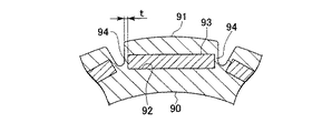
電動機や発電機等の回転電機に使用される回転子として、ロータ鉄心に永久磁石を埋め込んだ永久磁石式回転子が知られている(例えば、特許文献1、特許文献2参照)。従来の永久磁石式回転子は、例えば図7に示すように、珪素鋼板を多数積層してなるロータ鉄心90の外周部に多数の突極部91を設け、各突極部91にロータ鉄心90の軸線方向に貫通する磁石挿入孔92を設け、各磁石挿入孔92に永久磁石片93を挿入配置して構成されている。ここで、突極部91において磁石挿入孔92の周方向外側に位置する部分(以下、保持部という)94の幅寸法tは、回転子中の漏れ磁束を減少させる等のため、狭くするのが好ましいとされている(例えば、特許文献3参照)。
【0003】
【特許文献1】
特開平5−284680号公報
【特許文献2】
特開平6−269140号公報
【特許文献3】
特開2002−209350号公報
【0004】
【発明が解決しようとする課題】
しかしながら、この保持部94は、永久磁石式回転子が回転したときに遠心力による応力が集中する部分であり、保持部94の幅寸法tを余り小さくすると機械的強度が低下してしまう。かといって、機械的強度を優先して保持部94の幅寸法tを大きくすると、永久磁石片93の磁束が短絡し、また、磁石発熱が大きくなって不利になる。
そこで、この発明は、磁気特性に優れ、発熱を抑制でき、且つ十分な機械的強度を備えた永久磁石式回転子を提供するものである。
【0005】
【課題を解決するための手段】
上記課題を解決するために、請求項1に係る発明は、外周部に突極部(例えば、後述する実施の形態における突極部23)を有し該突極部に磁石挿入孔(例えば、後述する実施の形態における磁石挿入孔24)が設けられたロータ鉄心(例えば、後述する実施の形態におけるロータヨーク20)と、前記磁石挿入孔に挿入された永久磁石片(例えば、後述する実施の形態における永久磁極片40)と、前記ロータ鉄心の端面に沿って配置され前記磁石挿入孔を閉塞する端面板(例えば、後述する実施の形態における端面板30A,30B)と、を備えた永久磁石式回転子(例えば、後述する実施の形態における永久磁石式回転子1)において、前記端面板は外周部に前記ロータ鉄心の軸線方向に突出する複数の係止爪(例えば、後述する実施の形態における係止爪34)を備え、この係止爪が前記突極部の外周面に係止されていることを特徴とする。
【0006】
このように構成することにより、遠心力によってロータ鉄心および永久磁石片に径方向外側へ引っ張る力が作用したときに、端面板の係止爪がこの力に抗することができる。すなわち、遠心力による応力の一部を端面板の係止爪で受けることができるので、磁石挿入孔に隣接する保持部における応力を低減することができ、保持部の幅寸法を小さくすることができる。
【0007】
請求項2に係る発明は、請求項1に記載の発明において、前記突極部の外周面の端部に段差部(例えば、後述する実施の形態における段差部26)が設けられ、この段差部に前記係止爪が係止されていることを特徴とする。
このように構成することにより、端面板の係止爪が突極部の外周面から出っ張ることがない。
【0008】
請求項3に係る発明は、外周部に突極部(例えば、後述する実施の形態における突極部23)を有し該突極部に磁石挿入孔(例えば、後述する実施の形態における磁石挿入孔24)が設けられたロータ鉄心(例えば、後述する実施の形態におけるロータヨーク20)と、前記磁石挿入孔に挿入された永久磁石片(例えば、後述する実施の形態における永久磁極片40)と、前記ロータ鉄心の端面に沿って配置され前記磁石挿入孔を閉塞する端面板(例えば、後述する実施の形態における端面板30A,30B)と、を備えた永久磁石式回転子(例えば、後述する実施の形態における永久磁石式回転子1)において、前記端面板は前記ロータ鉄心の軸線方向に突出する複数の係止爪(例えば、後述する実施の形態における係止爪35)を備え、この係止爪が前記磁石挿入孔に挿入された永久磁石片の外周面に係止されていることを特徴とする。
【0009】
このように構成することにより、遠心力によって永久磁石片に径方向外側へ引っ張る力が作用したときに、端面板の係止爪がこの力に抗することができる。すなわち、遠心力による応力の一部を端面板の係止爪で受けることができるので、磁石挿入孔に隣接する保持部における応力を低減することができ、保持部の幅寸法を小さくすることができる。
【0010】
【発明の実施の形態】
以下、この発明に係る永久磁石式回転子の実施の形態を図1から図6の図面を参照して説明する。
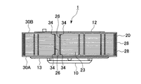
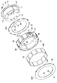
図1および図2は、電動機や発電機等の回転電機に使用可能な本発明に係る永久磁石式回転子(以下、回転子と略す)1の平面図と分解斜視図である。
回転子1は、ロータ10と、ロータヨーク(ロータ鉄心)20と、一対の端面板30A,30Bと、多数の永久磁極片40とから構成されている。
【0011】
ロータ10は中空ドラム状をなし鋳造または鍛造により一体に成形されており、円筒状のロータの外周面11と一端面12の境界部分となる角にはロータヨーク20を圧入する際のガイド用に面取り12aが形成され、一方、ロータの外周面11と他端面13の境界部分となる角には、端面板30Aを、他端面13から外方に延出して設けられる延出部13aに突き当てるための逃げ溝13bが形成されている。ロータの外周面11には周方向で等間隔に三本の溝14が軸線方向に沿って形成されている。
【0012】
端面板30A,30Bは全く同じものであるが、軸線方向に沿う取付方向を互いに逆にされている。ここでは端面板30Aについて説明し、端面板30Bの説明は省略する。端面板30Aは円環状をなし、板部31の中央に形成された孔32の内径は圧入する為にロータ10の外周面11の外径より若干小さく形成されている。また、板部31の内周側端部には三つの突起33が径方向内向きに設けられ、外周側端部には周方向所定間隔おきに多数の係止爪34が厚さ方向に直角に起立して設けられている。すなわち、係止爪34は端面板30Aの軸線方向に沿って突出している。尚、端面板30A,30Bの材質は例えば、非磁性体であるオーステナイト系ステンレス鋼SUS304で構成される。
【0013】
ロータヨーク20は、同一形状、同一寸法の電磁鋼板28を多数積層して構成されたものであり円環状をなしている。ロータヨーク20の中央には、ロータ10が挿入される貫通孔21が設けられており、その内周面には周方向等間隔に三つの突起22が設けられている。
また、ロータヨーク20はその外周部に多数の突極部23が設けられており、各突極部23の基部側には永久磁石片40が挿入される磁石挿入孔24が設けられている。
【0014】
図3に示すように、突極部23において磁石挿入孔24の周方向外側に位置する部分(以下、保持部という)25の幅寸法tは、永久磁極片40の磁束の短絡を抑制するため、および発熱を抑制するために、極めて小さく設定されている。さらに、ロータヨーク20の各突極部23の外周端の周方向両端部には、端面板30A,30Bの係止爪34とほぼ同じ幅寸法で係止爪34の厚みとほぼ同じ深さ寸法に形成された段差部26,26が設けられている。
【0015】
この回転子1は例えば次のようにして組み立てられる。
まず、端面板30Aをロータ10の一端面12側からロータ10の外周面11に圧入して嵌め込む。その際、端面板30Aの突起33をロータ10の外周面11の溝14に係合させながら圧入する。
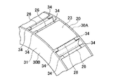
次に、ロータヨーク20をロータ10の一端面12側からロータ10の外周面11に圧入して嵌め込む。その際、ロータヨーク20の突起22をロータ10の外周面11の溝14に係合させながら圧入する。このように突起33,22を溝14に係合させながら圧入することで、端面板30Aの突起33とロータヨーク20の突起22が一致するように配置され、図4に示すように、端面板30Aの各係止爪34はロータヨーク20の突極部23の段差部26に係止される。これにより係止爪34は突極部23の外周面に係止されることとなる。
【0016】
続いて、ロータヨーク20の各磁石挿入孔24にそれぞれ永久磁極片40を一つずつ挿入し、その後、端面板30Bをロータ10の一端面12側からロータ10の外周面11に圧入して嵌め込む。その際、端面板30Bの突起33をロータ10の外周面11の溝14に係合させながら圧入する。従って、端面板30Aと同様に、端面板30Bの突起33とロータヨーク20の突起22が一致するように配置され、端面板30Bの各係止爪34はロータヨーク20の突極部23の段差部26に係止される。これにより、端面板30Bの係止爪34も突極部23の外周面に係止されることとなる。
【0017】
以上のように組み立てることにより、ロータ10と、ロータヨーク20と永久磁極片40と端面板30A,30Bが一体化され、図1に示すような回転子1が完成する。このように組み立てられた回転子では、各磁石挿入孔24の両端開口が端面板30A,30Bによって塞がれ、永久磁極片40がロータヨーク20から離脱するのが阻止される。なお、係止爪34はロータヨーク20の軸線方向両端近傍に配置された複数枚の電磁鋼板28の段差部26にだけ係止しており、軸線方向中央部に配置されている電磁鋼板28の段差部26には係止していない。このように構成することにより、電磁鋼板23aは複数種用意する必要がなく1種類で済ませることが可能である。
【0018】
このように構成された回転子1においては、ロータヨーク20の突起22および端面板30A,30Bの突起33がロータ10の溝14に係合しており、さらに、端面板30A,30Bの係止爪34がロータヨーク20の外周に形成された段差部26に係止しているので、ロータ10とロータヨーク20と端面板30A,30Bは周方向に互いにずれることがない。
【0019】
また、端面板30A,30Bの係止爪34がロータヨーク20の外周に形成された段差部26に係止しているので、回転子1が回転した時の遠心力によってロータヨーク20の突極部23および永久磁石片40に径方向外側へ引っ張る力が作用したときに、端面板30A,30Bの係止爪34とロータヨーク20の保持部25がこの力に対抗し、保持部25の破損を阻止する。つまり、遠心力による応力の一部を端面板30A,30Bの係止爪34が受けるようになるので、ロータヨーク20の保持部25における応力を低減することができる。その結果、保持部25の幅寸法tを小さくすることができる。
なお、係止爪34は段差部26に係止しているので、係止爪34の外面と突極部23の外周面が面一になり、回転電機のステータとロータヨーク20との隙間を広げないで済む。
【0020】
したがって、この回転子1においては、保持部25の幅寸法tを小さくしても回転子1の機械的強度を十分に高くすることができる。換言すると、保持部25の幅寸法tを大きくすることなく回転子1の機械的強度を高くすることができる。また、保持部25の幅寸法を小さくすることができるので、永久磁極片40の磁束の短絡を抑制することができ、発熱を抑制することができる。
【0021】
前述した実施の形態では、ロータヨーク20の突極部23に段差部26を設け、端面板30A,30Bの係止爪34を段差部26に係止するようにしているが、図5に示すように、端面板30A,30Bの板部31の所定部位に切り込みを入れて、この切り込みに囲まれた部分を軸線方向に突出させて係止爪35とし、図6に示すように、ロータヨーク20の各磁石挿入孔24の両端部に径方向外側へ膨出する爪挿入孔27を磁石挿入孔24に連続して設け、係止爪35を永久磁極片40の外周面の両端部に係止させるようにしてもよい。
【0022】
このようにすると、回転子1が回転した時の遠心力によって永久磁石片40に径方向外側へ引っ張る力が作用したときに、端面板30A,30Bの係止爪35がこの力に対抗して永久磁極片40が径方向外側に移動するのを阻止する。その結果、永久磁極片40を径方向外側に引っ張る力はロータヨーク20の突極部23に作用しなくなり、保持部25における遠心力による応力を低減することができるので、保持部25の幅寸法tを小さくすることができる。
したがって、このように構成しても、保持部25の幅寸法tを大きくすることなく回転子1の機械的強度を高くすることができ、また、保持部25の幅寸法を小さくすることができるので、永久磁極片40の磁束の短絡を抑制することができ、発熱を抑制することができる。
【0023】
【発明の効果】
以上説明するように、請求項1に係る発明によれば、遠心力による応力の一部を端面板の係止爪で受けることができるので、磁石挿入孔に隣接する保持部の応力を低減することができ、保持部の幅寸法を小さくすることができる。したがって、前記保持部の幅寸法を大きくすることなく永久磁石式回転子の機械的強度を十分に高くすることができ、また、保持部の幅寸法を小さくして、永久磁極片の磁束の短絡を抑制することができ、発熱を抑制することができるという優れた効果が奏される。
【0024】
請求項2に係る発明によれば、請求項1の効果に加えて、端面板の係止爪が突極部の外周面から出っ張ることがないので、ロータ鉄心とステータとの隙間を広げずに済むという効果がある。
【0025】
請求項3に係る発明によれば、遠心力による応力の一部を端面板の係止爪で受けることができるので、磁石挿入孔に隣接する保持部の応力を低減することができ、保持部の幅寸法を小さくすることができる。したがって、前記保持部の幅寸法を大きくすることなく永久磁石式回転子の機械的強度を十分に高くすることができ、また、保持部の幅寸法を小さくして、永久磁極片の磁束の短絡を抑制することができ、発熱を抑制することができるという優れた効果が奏される。
【図面の簡単な説明】
【図1】この発明の第1の実施の形態における永久磁石式回転子の平面図である。
【図2】前記第1の実施の形態における永久磁石式回転子の分解斜視図である。
【図3】前記第1の実施の形態における永久磁石式回転子の要部断面図である。
【図4】前記第1の実施の形態における永久磁石式回転子の要部外観斜視図である。
【図5】この発明の第2の実施の形態における永久磁石式回転子に使用される端面板の要部外観斜視図である。
【図6】前記第2の実施の形態における永久磁石式回転子の要部断面図である。
【図7】従来の永久磁石式回転子の要部断面図である。
【符号の説明】
1 永久磁石式回転子
20 ロータヨーク(ロータ鉄心)
23 突極部
24 磁石挿入孔
26 段差部
30A,30B 端面板
34,35 係止爪
40 永久磁極片[0001]
TECHNICAL FIELD OF THE INVENTION
The present invention relates to a permanent magnet rotor having a permanent magnet embedded in a rotor core.
[0002]
[Prior art]
2. Description of the Related Art As a rotor used in a rotating electric machine such as an electric motor or a generator, a permanent magnet rotor in which a permanent magnet is embedded in a rotor core is known (for example, see Patent Documents 1 and 2). In the conventional permanent magnet type rotor, for example, as shown in FIG. 7, a large number of
[0003]
[Patent Document 1]
JP-A-5-284680 [Patent Document 2]
JP-A-6-269140 [Patent Document 3]
JP-A-2002-209350
[Problems to be solved by the invention]
However, the
Accordingly, the present invention provides a permanent magnet rotor having excellent magnetic properties, capable of suppressing heat generation, and having sufficient mechanical strength.
[0005]
[Means for Solving the Problems]
In order to solve the above problem, the invention according to claim 1 has a salient pole portion (for example, a
[0006]
With this configuration, when a centrifugal force causes a radially outward pulling force to act on the rotor core and the permanent magnet pieces, the locking claws of the end face plate can resist this force. That is, since a part of the stress due to the centrifugal force can be received by the locking claw of the end face plate, the stress in the holding portion adjacent to the magnet insertion hole can be reduced, and the width of the holding portion can be reduced. it can.
[0007]
According to a second aspect of the present invention, in the first aspect of the present invention, a step portion (for example, a
With this configuration, the locking claw of the end face plate does not protrude from the outer peripheral surface of the salient pole portion.
[0008]
The invention according to claim 3 has a salient pole portion (for example, a
[0009]
With this configuration, when a centrifugal force exerts a radially outward pulling force on the permanent magnet pieces, the locking claws of the end face plate can resist this force. That is, since a part of the stress due to the centrifugal force can be received by the locking claw of the end face plate, the stress in the holding portion adjacent to the magnet insertion hole can be reduced, and the width of the holding portion can be reduced. it can.
[0010]
BEST MODE FOR CARRYING OUT THE INVENTION
Hereinafter, an embodiment of a permanent magnet type rotor according to the present invention will be described with reference to the drawings of FIGS.
1 and 2 are a plan view and an exploded perspective view of a permanent magnet type rotor (hereinafter abbreviated as a rotor) 1 according to the present invention, which can be used for a rotating electric machine such as a motor or a generator.
The rotor 1 includes a
[0011]
The
[0012]
The
[0013]
The
The
[0014]
As shown in FIG. 3, the width dimension t of a portion (hereinafter, referred to as a holding portion) 25 of the
[0015]
The rotor 1 is assembled as follows, for example.
First, the
Next, the
[0016]
Subsequently, one permanent
[0017]
By assembling as described above, the
[0018]
In the rotor 1 configured as described above, the
[0019]
In addition, since the locking
Since the locking
[0020]
Therefore, in the rotor 1, the mechanical strength of the rotor 1 can be sufficiently increased even if the width dimension t of the holding
[0021]
In the above-described embodiment, the
[0022]
In this way, when the centrifugal force generated when the rotor 1 rotates causes a radially outward pulling force to act on the
Therefore, even with this configuration, the mechanical strength of the rotor 1 can be increased without increasing the width t of the holding
[0023]
【The invention's effect】
As described above, according to the first aspect of the invention, a part of the stress due to the centrifugal force can be received by the locking claw of the end face plate, so that the stress of the holding portion adjacent to the magnet insertion hole is reduced. The width of the holding portion can be reduced. Therefore, the mechanical strength of the permanent magnet type rotor can be sufficiently increased without increasing the width of the holding portion, and the width of the holding portion is reduced to short-circuit the magnetic flux of the permanent magnetic pole piece. , And an excellent effect that heat generation can be suppressed.
[0024]
According to the invention according to
[0025]
According to the invention according to claim 3, a part of the stress due to the centrifugal force can be received by the locking claw of the end face plate, so that the stress of the holding portion adjacent to the magnet insertion hole can be reduced, and the holding portion can be reduced. Can be reduced in width. Therefore, the mechanical strength of the permanent magnet type rotor can be sufficiently increased without increasing the width of the holding portion, and the width of the holding portion is reduced to short-circuit the magnetic flux of the permanent magnetic pole piece. , And an excellent effect that heat generation can be suppressed.
[Brief description of the drawings]
FIG. 1 is a plan view of a permanent magnet type rotor according to a first embodiment of the present invention.
FIG. 2 is an exploded perspective view of the permanent magnet rotor according to the first embodiment.
FIG. 3 is a sectional view of a main part of the permanent magnet type rotor according to the first embodiment.
FIG. 4 is an external perspective view of a main part of the permanent magnet rotor according to the first embodiment.
FIG. 5 is an external perspective view of a main part of an end face plate used in a permanent magnet type rotor according to a second embodiment of the present invention.
FIG. 6 is a sectional view of a main part of a permanent magnet rotor according to the second embodiment.
FIG. 7 is a sectional view of a main part of a conventional permanent magnet type rotor.
[Explanation of symbols]
1 permanent
23
Claims (3)
前記端面板は外周部に前記ロータ鉄心の軸線方向に突出する複数の係止爪を備え、この係止爪が前記突極部の外周面に係止されていることを特徴とする永久磁石式回転子。A rotor core having a salient pole portion on an outer peripheral portion and a magnet insertion hole provided in the salient pole portion; a permanent magnet piece inserted into the magnet insertion hole; and a magnet arranged along an end face of the rotor core. An end plate closing the insertion hole, and a permanent magnet type rotor having:
The end plate is provided with a plurality of locking claws protruding in an axial direction of the rotor core on an outer peripheral portion, and the locking claws are locked on an outer peripheral surface of the salient pole portion. Rotor.
前記端面板は前記ロータ鉄心の軸線方向に突出する複数の係止爪を備え、この係止爪が前記磁石挿入孔に挿入された永久磁石片の外周面に係止されていることを特徴とする永久磁石式回転子。A rotor core having a salient pole portion on an outer peripheral portion and a magnet insertion hole provided in the salient pole portion; a permanent magnet piece inserted into the magnet insertion hole; and a magnet arranged along an end face of the rotor core. An end plate closing the insertion hole, and a permanent magnet type rotor having:
The end plate includes a plurality of locking claws protruding in the axial direction of the rotor core, and the locking claws are locked to an outer peripheral surface of a permanent magnet piece inserted into the magnet insertion hole. Permanent magnet rotor.
Priority Applications (1)
| Application Number | Priority Date | Filing Date | Title |
|---|---|---|---|
| JP2003024654A JP4248887B2 (en) | 2003-01-31 | 2003-01-31 | Permanent magnet rotor |
Applications Claiming Priority (1)
| Application Number | Priority Date | Filing Date | Title |
|---|---|---|---|
| JP2003024654A JP4248887B2 (en) | 2003-01-31 | 2003-01-31 | Permanent magnet rotor |
Publications (3)
| Publication Number | Publication Date |
|---|---|
| JP2004236477A true JP2004236477A (en) | 2004-08-19 |
| JP2004236477A5 JP2004236477A5 (en) | 2005-12-15 |
| JP4248887B2 JP4248887B2 (en) | 2009-04-02 |
Family
ID=32953129
Family Applications (1)
| Application Number | Title | Priority Date | Filing Date |
|---|---|---|---|
| JP2003024654A Expired - Fee Related JP4248887B2 (en) | 2003-01-31 | 2003-01-31 | Permanent magnet rotor |
Country Status (1)
| Country | Link |
|---|---|
| JP (1) | JP4248887B2 (en) |
Cited By (2)
| Publication number | Priority date | Publication date | Assignee | Title |
|---|---|---|---|---|
| WO2012014836A1 (en) * | 2010-07-30 | 2012-02-02 | 本田技研工業株式会社 | Rotor and motor |
| CN103546009A (en) * | 2012-07-12 | 2014-01-29 | 株式会社日立制作所 | Permanent magnet synchronous generator |
Citations (6)
| Publication number | Priority date | Publication date | Assignee | Title |
|---|---|---|---|---|
| JPH06269140A (en) * | 1993-03-12 | 1994-09-22 | Toshiba Corp | Permanent magnet-type rotor |
| JPH10309051A (en) * | 1997-03-06 | 1998-11-17 | Hitachi Ltd | Permanent-magnet rotating electric machine |
| JPH11275831A (en) * | 1998-01-26 | 1999-10-08 | Robert Bosch Gmbh | Synchronous apparatus |
| JP2001037122A (en) * | 1999-07-23 | 2001-02-09 | Sankyo Seiki Mfg Co Ltd | Rotor for motor |
| JP2001314052A (en) * | 2000-02-25 | 2001-11-09 | Nissan Motor Co Ltd | Rotor structure of synchronous motor |
| JP2001352702A (en) * | 2000-04-03 | 2001-12-21 | Honda Motor Co Ltd | Permanent magnet rotary electric machine |
-
2003
- 2003-01-31 JP JP2003024654A patent/JP4248887B2/en not_active Expired - Fee Related
Patent Citations (6)
| Publication number | Priority date | Publication date | Assignee | Title |
|---|---|---|---|---|
| JPH06269140A (en) * | 1993-03-12 | 1994-09-22 | Toshiba Corp | Permanent magnet-type rotor |
| JPH10309051A (en) * | 1997-03-06 | 1998-11-17 | Hitachi Ltd | Permanent-magnet rotating electric machine |
| JPH11275831A (en) * | 1998-01-26 | 1999-10-08 | Robert Bosch Gmbh | Synchronous apparatus |
| JP2001037122A (en) * | 1999-07-23 | 2001-02-09 | Sankyo Seiki Mfg Co Ltd | Rotor for motor |
| JP2001314052A (en) * | 2000-02-25 | 2001-11-09 | Nissan Motor Co Ltd | Rotor structure of synchronous motor |
| JP2001352702A (en) * | 2000-04-03 | 2001-12-21 | Honda Motor Co Ltd | Permanent magnet rotary electric machine |
Cited By (3)
| Publication number | Priority date | Publication date | Assignee | Title |
|---|---|---|---|---|
| WO2012014836A1 (en) * | 2010-07-30 | 2012-02-02 | 本田技研工業株式会社 | Rotor and motor |
| CN103546009A (en) * | 2012-07-12 | 2014-01-29 | 株式会社日立制作所 | Permanent magnet synchronous generator |
| JP2014023173A (en) * | 2012-07-12 | 2014-02-03 | Hitachi Ltd | Permanent-magnet synchronous motor |
Also Published As
| Publication number | Publication date |
|---|---|
| JP4248887B2 (en) | 2009-04-02 |
Similar Documents
| Publication | Publication Date | Title |
|---|---|---|
| US10763711B2 (en) | Motor rotor including rotor core and manufacturing method therefor | |
| JP5480176B2 (en) | Rotating machine rotor | |
| KR101566047B1 (en) | Spoke type permanent magnet motor | |
| JP4566319B2 (en) | Permanent magnet embedded rotor for permanent magnet motor | |
| JP2005184957A (en) | Permanent magnet type reluctance rotary electric machine | |
| JP6512060B2 (en) | Rotor of electric rotating machine | |
| JP2009136040A (en) | Rotor of rotary electric machine | |
| JP2012165482A (en) | Rotor for rotary electric machine | |
| JP5347588B2 (en) | Embedded magnet motor | |
| JP2004023976A (en) | Rotor of outside rotating type permanent magnet motor | |
| JP2007330030A (en) | Structure for fixing ring magnet in rotor and motor for electric power steering | |
| JP2014045634A (en) | Rotor and rotary electric machine including the same | |
| JP2004023864A (en) | Rotor of permanent magnet rotary electric machine | |
| JP2004180383A (en) | Stator and its manufacturing method | |
| JP2004328963A (en) | Manufacturing method of rotor for electric motor, and the rotor for electric motor | |
| JP2006121870A (en) | Motor device | |
| JP6074887B2 (en) | Gap gauge used for assembling electric motor and method for manufacturing electric motor | |
| JP2016034216A (en) | Rotor and motor | |
| JP2005168127A (en) | Permanent magnet type rotor | |
| JP2009106001A (en) | Rotary electric machine | |
| JP2014225935A (en) | Permanent magnet type rotary electric machine | |
| JP4318959B2 (en) | Permanent magnet rotor and brushless motor | |
| JP4397598B2 (en) | stator | |
| JP2004236477A (en) | Permanent magnet rotor | |
| JP2005210828A (en) | Rotating electric machine and rotor therefor |
Legal Events
| Date | Code | Title | Description |
|---|---|---|---|
| A521 | Written amendment |
Free format text: JAPANESE INTERMEDIATE CODE: A523 Effective date: 20051026 |
|
| A621 | Written request for application examination |
Free format text: JAPANESE INTERMEDIATE CODE: A621 Effective date: 20051026 |
|
| A977 | Report on retrieval |
Free format text: JAPANESE INTERMEDIATE CODE: A971007 Effective date: 20080709 |
|
| A131 | Notification of reasons for refusal |
Free format text: JAPANESE INTERMEDIATE CODE: A131 Effective date: 20080715 |
|
| A521 | Written amendment |
Free format text: JAPANESE INTERMEDIATE CODE: A523 Effective date: 20080910 |
|
| TRDD | Decision of grant or rejection written | ||
| A01 | Written decision to grant a patent or to grant a registration (utility model) |
Free format text: JAPANESE INTERMEDIATE CODE: A01 Effective date: 20090106 |
|
| A01 | Written decision to grant a patent or to grant a registration (utility model) |
Free format text: JAPANESE INTERMEDIATE CODE: A01 |
|
| A61 | First payment of annual fees (during grant procedure) |
Free format text: JAPANESE INTERMEDIATE CODE: A61 Effective date: 20090114 |
|
| FPAY | Renewal fee payment (event date is renewal date of database) |
Free format text: PAYMENT UNTIL: 20120123 Year of fee payment: 3 |
|
| R150 | Certificate of patent or registration of utility model |
Free format text: JAPANESE INTERMEDIATE CODE: R150 |
|
| FPAY | Renewal fee payment (event date is renewal date of database) |
Free format text: PAYMENT UNTIL: 20120123 Year of fee payment: 3 |
|
| FPAY | Renewal fee payment (event date is renewal date of database) |
Free format text: PAYMENT UNTIL: 20130123 Year of fee payment: 4 |
|
| FPAY | Renewal fee payment (event date is renewal date of database) |
Free format text: PAYMENT UNTIL: 20130123 Year of fee payment: 4 |
|
| FPAY | Renewal fee payment (event date is renewal date of database) |
Free format text: PAYMENT UNTIL: 20140123 Year of fee payment: 5 |
|
| LAPS | Cancellation because of no payment of annual fees |