WO2012011301A1 - 映像記録システム、映像記録装置、管理装置および通信量制御方法 - Google Patents
映像記録システム、映像記録装置、管理装置および通信量制御方法 Download PDFInfo
- Publication number
- WO2012011301A1 WO2012011301A1 PCT/JP2011/056419 JP2011056419W WO2012011301A1 WO 2012011301 A1 WO2012011301 A1 WO 2012011301A1 JP 2011056419 W JP2011056419 W JP 2011056419W WO 2012011301 A1 WO2012011301 A1 WO 2012011301A1
- Authority
- WO
- WIPO (PCT)
- Prior art keywords
- data
- network
- communication
- data recording
- traffic shaping
- Prior art date
- Legal status (The legal status is an assumption and is not a legal conclusion. Google has not performed a legal analysis and makes no representation as to the accuracy of the status listed.)
- Ceased
Links
Images


Classifications
-
- H—ELECTRICITY
- H04—ELECTRIC COMMUNICATION TECHNIQUE
- H04N—PICTORIAL COMMUNICATION, e.g. TELEVISION
- H04N21/00—Selective content distribution, e.g. interactive television or video on demand [VOD]
- H04N21/60—Network structure or processes for video distribution between server and client or between remote clients; Control signalling between clients, server and network components; Transmission of management data between server and client, e.g. sending from server to client commands for recording incoming content stream; Communication details between server and client
- H04N21/63—Control signaling related to video distribution between client, server and network components; Network processes for video distribution between server and clients or between remote clients, e.g. transmitting basic layer and enhancement layers over different transmission paths, setting up a peer-to-peer communication via Internet between remote STB's; Communication protocols; Addressing
- H04N21/637—Control signals issued by the client directed to the server or network components
- H04N21/6373—Control signals issued by the client directed to the server or network components for rate control, e.g. request to the server to modify its transmission rate
-
- H—ELECTRICITY
- H04—ELECTRIC COMMUNICATION TECHNIQUE
- H04N—PICTORIAL COMMUNICATION, e.g. TELEVISION
- H04N21/00—Selective content distribution, e.g. interactive television or video on demand [VOD]
- H04N21/20—Servers specifically adapted for the distribution of content, e.g. VOD servers; Operations thereof
- H04N21/21—Server components or server architectures
- H04N21/218—Source of audio or video content, e.g. local disk arrays
- H04N21/2187—Live feed
Definitions
- the present invention relates to a data recording system that controls the amount of communication between devices on a network, and in particular, a data recording system that controls the amount of communication based on “discarded number of transmitted packets” information acquired using an SNMP management function.
- the present invention relates to a data recording device, a management device, and a communication amount control method.
- an image recording system such as an image monitoring system that includes a monitoring camera, an image recording device, a network switch, and an image display device and monitors image data and records image data in the image recording device has been operated.
- Patent Document 1 is an image distribution system having a function of accumulating image signals on a network, and particularly discloses a function of displaying an image distribution status.
- Patent Document 1 JP 2008-148347 A
- the transmission of the transmission packet is performed in a network switch unit that handles data transmission. Discard may occur.
- Patent Document 1 described above does not describe how to deal with the discard of the transmission packet.
- An object of the present invention is to provide an image recording system, an image recording apparatus, a management apparatus, and a communication amount control method that perform communication at a communication speed at which transmission packets are not discarded.
- a data recording system of the present invention is a data recording system having a data transmission device and a data recording device connected to the data transmission device via a network, the data recording device or the data recording device Using an SNMP management function installed in a device on the network, packet discard information in communication between the data sending device and the data recording device is acquired, and the data sending device and the data are acquired based on the packet discard information. Controlling the amount of communication with the recording apparatus.
- the data recording system further includes a network switch to which the data transmission device is connected and which converges and outputs data input from the data transmission device, and the data recording device or the device on the network includes A packet discard information of the network switch is acquired using an SNMP management function, and a transmission data amount of the data transmission device is controlled based on the packet discard information.
- the data recording apparatus or the apparatus on the network controls until the acquired packet discard information becomes 0 or a predetermined value or less.
- the data recording device or the device on the network increases the transmission data amount of the data transmission device by a predetermined value when the acquired packet discard information is 0 for a predetermined period, When the packet discard information exceeds 0, the value of the immediately previous transmission data amount is controlled as the transmission data amount of the data transmission device.
- the data recording device or the device on the network acquires the input data amount and output data amount information of the network switch, and the network switch has the output data amount smaller than the input data amount as the packet. It is characterized in that it is a target for obtaining discard information.
- a data recording apparatus is a data recording apparatus that communicates with a data transmission apparatus via a network, has an SNMP management function, and uses the SNMP management function. Packet discard information in communication with a data device is acquired, and the amount of communication with the data transmission device is controlled based on the packet discard information.
- the management device of the present invention is a management device that manages the amount of communication on the network between the data transmission device and the data recording device, and is provided on the network, Packet discard information in communication between the data transmission device and the data recording device is acquired using an SNMP management function, and the communication amount between the data transmission device and the data recording device is determined based on the packet discard information. It is characterized by controlling.
- a communication data amount control method of the present invention is a communication amount control method for controlling a communication amount on a network between a data transmission device and a data recording device, and the data transmission device Packet discard information in communication between the data recording apparatus and the data recording apparatus using an SNMP management function, and based on the acquired packet discard information, the amount of communication data between the data sending apparatus and the data recording apparatus It is characterized by controlling.
- FIG. 1 is a block diagram showing an example of the configuration of an image recording system according to an embodiment of the present invention.
- the block diagram which shows the structure of the network switch which concerns on one Embodiment of this invention.
- the block diagram which shows the structure of the network switch which concerns on one Embodiment of this invention.
- Explanatory drawing which shows an example of the data transmission timing in the network switch which concerns on one Embodiment of this invention.
- Explanatory drawing which shows an example of the data transmission timing in case the transmission packet in the network switch which concerns on one Embodiment of this invention is discarded.
- 6 is a flowchart showing an example of a traffic shaping control process in the image recording system according to the embodiment of the present invention.
- FIG. 4 is an explanatory diagram illustrating a state in which a transmission packet is prevented from being discarded by traffic shaping control in the network management table and the traffic shaping control management table held in the recording apparatus of the image recording system according to the embodiment of the present invention.
- FIG. 4 is an explanatory diagram illustrating a state in which a transmission packet is prevented from being discarded by traffic shaping control in the network management table and the traffic shaping control management table held in the recording apparatus of the image recording system according to the embodiment of the present invention.
- FIG. 4 is an explanatory diagram illustrating a state in which a transmission packet is prevented from being discarded by traffic shaping control in the network management table and the traffic shaping control management table held in the recording apparatus of the image recording system according to the embodiment of the present invention.
- the transmission packet is discarded by the stepwise traffic shaping control.
- Explanatory drawing which shows a mode that it avoided that.
- the transmission packet is discarded by the stepwise traffic shaping control.
- Explanatory drawing which shows a mode that it avoided that.
- Explanatory drawing which shows a mode that the transmission packet was avoided by traffic shaping control in the image recording system which concerns on one Embodiment of this invention.
- Explanatory drawing which shows a mode that the transmission packet was avoided by traffic shaping control in the image recording system which concerns on one Embodiment of this invention.
- 7 is a flowchart showing an example of a traffic shaping control process when automatically selecting a network switch to be monitored in traffic shaping control according to another embodiment of the present invention.
- the block diagram which shows an example of a structure of the image recording system which concerns on other one Embodiment of this invention. Description showing a state in which a transmission packet is avoided from being discarded by traffic shaping control in a network management table and a traffic shaping control management table held in a management apparatus of an image recording system according to another embodiment of the present invention.
- Figure. 9 is a flowchart showing an example of a traffic shaping control process in an image recording system according to another embodiment of the present invention.
- FIG. 1 is a block diagram illustrating an example of a configuration of an image recording system according to an embodiment of the present invention
- FIGS. 2A and 2B are blocks illustrating a configuration of a network switch of the image recording system according to an embodiment of the present invention
- FIG. 3 is an explanatory diagram showing an example of data transmission timing in the network switch of the image recording system according to the embodiment of the present invention
- FIG. 4 is a diagram of the network switch of the image recording system according to the embodiment of the present invention. It is explanatory drawing which shows an example of the data transmission timing in case a transmission packet is discarded.
- the image recording system has, as an example, an edge switch 1 and a plurality of cameras 8, 9, 10 connected thereto in the first monitoring area.
- the edge switch 2 In the second monitoring area, the edge switch 2 and a plurality of cameras 11, 12, 13 connected thereto are provided.
- the edge switch 3 In the third monitoring area, the edge switch 3 and a plurality of cameras connected thereto are provided. Cameras 14, 15 and 16 are provided.
- this image recording system has an edge switch 6, a plurality of recording devices 17, 18, 19 and a management device 20 connected thereto in the recording area. Further, this image recording system has an edge switch 7 and a plurality of display devices 21, 22, and 23 connected thereto in the monitor area. These monitoring area, recording area, and monitoring area are connected via a center switch 4 and a center switch 5.
- At least the edge switch 1, the center switch 4, and the center switch 5 have SNMP (Simple Network Management Protocol) processing units 64, 65, and 66, respectively.
- at least the recording device 17 has an SNMP management unit 67.
- the present invention is not limited to this, and the edge switches 2, 3, 7 may also have SNMP processing units, and the recording devices 18, 19 may also have SNMP management units.
- This SNMP management unit has an SNMP manager (NMS: Network Management Station) function, and grasps the state of network devices in order to control network traffic and maintain stable communication quality. Further, the SNMP processing unit has an SNMP agent function, and holds management information called MIB (Management Information Base). In this MIB, information related to the hardware interface possessed by the device is managed in a portion called an interface group. As one piece of the management information, there is information indicating “ifOutDiscard: number of discarded transmission packets”.
- the recording devices 17, 18, and 19 cameras 8,... 16 connected to the monitoring area are registered, and connected to the corresponding cameras via a network, and image data is recorded at a pre-registered frame rate. Is acquired and an image is recorded.
- the management device 20 manages information such as the IP addresses of the cameras 8,..., 16 and the recording devices 17, 18, and 19 and the display device of the entire system in a database and performs fault monitoring.
- the recording device 17 records the images of the cameras 8 to 10
- the recording device 18 records the images of the cameras 11 to 13
- the recording device 19 records the images of the cameras 14 to 16.
- the display devices 21, 22, and 23 in the monitor area are connected to a target camera via a network, acquire a live image, and display the image on the display unit of the own device. Also, when confirming the recorded image of an arbitrary camera, specify “camera name etc.”, “recorded image date / time”, “recorded image playback control”, etc., and connect to the target recording device via the network. And the recorded image is displayed on the display unit of the own device.
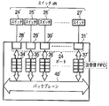
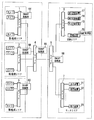
- FIG. 2A it is assumed that the cameras 24... 27 corresponding to the cameras 8... 16 described above are connected to the physical ports 28 to 31 of the edge switches 1, 2 and 3.
- the physical port 32 and the physical port 33 are used as uplink ports to the center switch 4 which is an adjacent network switch.
- the physical port 28 to the physical port 31 are 24 ports in total
- the physical port 32 and the physical port 33 are 2 ports in total. Packet data input / output from each physical port is exchanged via the input / output buffers 34 to 39 and the backplane 40.
- the backplane 40 in the normal network switch has the capability of enabling transfer at a transfer rate higher than the total transfer rate of the data amount input / output from the physical port.
- the physical ports 28 'to 31' of the center switch 4 are connected to the uplink ports of the edge switches 1,... 3 described above (other edge switches may be connected). Shall be.
- the physical ports 28 'to 31' are a total of 24 ports. Packet data input / output from each physical port is exchanged via the input / output buffers 34'-37 'and the backplane 40'. If the transfer rate of the physical ports 28 'to 31' is defined as 1000 Mbps, at least 48 Gbps transmission rate is required for the backplane. Therefore, the transmission rate for the backplane 40 ′ in the normal network switch has the capability of enabling transfer at a transfer rate higher than the total transfer rate of the data amount input from the physical port.
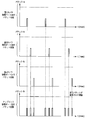
- the transmission packet is transferred from the uplink of the physical port 33 to the adjacent network switch. Indicates the state of the number. If the packet transfer timing of data input from the physical ports 28 to 31 is different, the packet data output from the uplink of the physical port 33 is not reached because the number of packets has not reached the threshold for discarding the number of transmitted packets. Are transferred without being destroyed.
- FIG. 4 shows the number of packets transferred from the uplink of the physical port 33 to the adjacent network switch when data from the cameras connected to the physical ports 28 to 31 are output at the same timing. Indicates the state.
- the packet transfer timings of data input from the physical ports 28 to 31 overlap the packet data output from the uplink of the physical port 33 is discarded if it exceeds the threshold of the number of packets that can be transmitted. It becomes.
- This phenomenon is because the transmission rate of the backplane 40 is larger than the transfer rate obtained by adding up the amount of data inputted / outputted from each physical port. It will occur as a difference. For this reason, input / output buffers 34 to 39 are provided for each physical port, and the packet data flowing from the backplane 40 in a burst (large amount) by this buffer is output from the physical port while adjusting the output timing. I'm in charge.
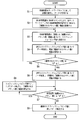
- Example 1 Next, the traffic control in the image recording system according to the embodiment of the present invention will be described with reference to the flowchart of FIG. 5, the management tables of FIGS. 6A to 6C and FIGS. 7A to 7B, and the data transmission timings of FIGS. This will be described in detail below.
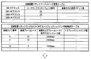
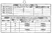
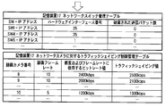
- the traffic control in the image recording system according to the embodiment of the present invention is based on the traffic shaping value according to the “number of discarded transmission packets” information acquired by the SNMP management unit 67. Is controlled step by step. 6A to 6C and FIGS. 7A to 7B sequentially show the results of a series of stepwise controls for one traffic process, and FIG. 6C is assumed to lead to FIG. 7A.
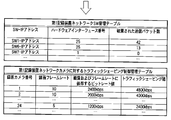
- the recording device 17 holds a network switch management table as shown in FIGS. 6A to 6C.
- the purpose of this management table is “the number of discarded transmission packets” at the corresponding physical port (hardware interface number) in the network switch of the IP address shown in the management table by the SNMP management unit 67 installed in the recording device 17. Is to manage.
- the network switch information may be added or updated by detecting the topology or device on the network.
- the recording device 17 holds a traffic shaping control management table for the network camera as shown in FIGS. 6A to 6C.
- the purpose of this management table is to perform traffic shaping on the data sent from the camera by registering “recording frame rate” and “bit rate value depending on image quality and frame rate” determined for each camera. It is.
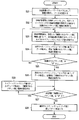
- the recording device 17 requests an image from the network camera, the network camera transfers image data to the recording device 17, and the recording device 17 receives the image data and records it at the set frame rate (S1). ).
- the SNMP management unit 67 acquires the “number of discarded packets” information from the MIB held by the SNMP processing unit of each network switch by the SNMP command, and updates the network switch management table (S2).
- the SNMP management unit 67 determines a traffic shaping value for the camera based on the acquired “number of discarded packets” information, and updates the traffic shaping control management table (S3).
- the traffic shaping value is always the limit value (lower limit) of the “bit rate value depending on image quality and frame rate” for the network camera. These conditions are the same when the traffic shaping value is set in the subsequent steps.
- the camera transfers the data using the traffic shaping value determined in S3 as the transfer rate, acquires the “number of discarded packets” information again, and updates the network switch management table (S4).
- the previous value is determined to be the optimum value of the traffic shaping value (transfer rate) for the camera, and the traffic shaping control management table is updated.
- the camera transfers data with the most recent traffic shaping value as the optimum transfer rate.
- Traffic shaping is performed with “2500 kbps”.
- the number of discarded transmission packets of SW1 is “0”, and it is determined that all transmission packets have been transmitted. Thereafter, the data is transferred at a transfer rate of 2500 kbps.
- the switch 1 has been described as an example, but the SNMP processing unit is also provided in the switch 2 and the switch 3, and at the same time, the “number of discarded transmission packets” is acquired and connected to each switch. It is desirable that traffic shaping is performed on the cameras, and it is possible to operate the system so as to control network traffic and maintain stable communication quality in the entire network monitoring system.
- S5 and S7 are “0” here, it is also possible to use a value determined by the user or a value derived from traffic information as a threshold value and whether or not it is a predetermined threshold value or less.
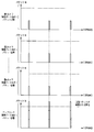
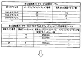
- the effects of these network traffic controls are transmitted from the cameras connected to the physical ports 28 to 31 of the edge switch 1 (SW1 in the table) as shown in the management table of FIG. 8A and the management table of FIG. 8B.
- This can be understood from the reduction in the number of packets when traffic shaping is applied to data. That is, as shown in the improved management table of FIG. 8B, the packet data output from the uplink of the physical port 33 is output at the same timing as the data from the camera by network traffic control (traffic shaping processing). Even in such a case, stable network communication can be realized with an optimum communication amount without exceeding the threshold of the number of packets that can be transmitted.
- FIG. 9 is a flowchart illustrating an example of a traffic shaping control process when a network switch to be monitored is automatically selected. This embodiment differs from the first embodiment described with reference to the flowchart of FIG. 5 in S12 and S13, and the other points are the same and will be omitted as much as possible.
- the recording device 17 requests an image from the network camera and receives data (S11: corresponding to S1 in FIG. 5).
- the SNMP management unit 67 measures the input data amount on the input side and the output data amount on the uplink port side of each switch 1, 2, 3, 4, 5, 6, 7, etc., and determines the relationship.
- the network switch management table and the traffic shaping control management table are updated with the network switch whose input data amount is larger than the output data amount being monitored (S12).
- the SNMP management unit 67 may initially measure the amount of data and add it. However, all the switch information is acquired in advance. When the input data amount is less than or equal to the output data amount, it may be excluded from the monitoring target.
- the SNMP management unit 67 acquires the “number of discarded packets” information from the MIB held by the SNMP processing unit of the network switch to be monitored by the SNMP command (S13). ). Thereafter, the same processing as that of the first embodiment described in FIG. 5 is performed (S14 to S20: corresponding to S3 to 9 in FIG. 5).
- the network switch to be monitored since only the network switch to be monitored can be monitored, less information is managed, and the network can be managed more simply and easily.
- Example 3 The case where traffic shaping is performed by the SNMP management unit 67 installed in the recording devices 17, 18, and 19 has been described above. However, as shown in FIG. 10, an SNMP management unit 70 is installed in the management device 20, holds a network switch management table as shown in FIG. Even if the operation for performing traffic shaping is adopted, similarly, it becomes possible to avoid the discard of the transmission packet and perform the smooth network communication.
- the traffic shaping control in this case will be described below.
- the edge switch 1, the edge switch 2, the edge switch 3, the center switch 4, and the center switch 5 have SNMP (Simple Network Management Protocol) processing units 64, 65, and 66, respectively.
- the management device 20 has an SNMP management unit 70.
- the SNMP management unit 70 of the management apparatus 20 has the network switch management table shown in FIG. 11, manages information such as the IP address, hardware interface number, and the number of discarded transmission packets of each network switch. A state in which the management apparatus collectively manages the traffic shaping control management table of the apparatus will be described.
- the SNMP management unit 70 of the management device 20 has a network switch management table for managing each network switch on the network shown in FIG. 11, and the recording devices 17 to 19 are networks managed by each recording device. Each has a traffic shaping control management table for the camera.
- the SNMP management unit 70 of the management apparatus 20 acquires “discarded packet number” information from the MIB held by the SNMP processing unit of each network switch by the SNMP command, and “discarded packet number” in the network switch management table. Information is updated (S22).
- the SNMP management unit 70 determines the traffic shaping value for the network camera managed by the recording devices 17 to 19 according to the “number of discarded transmission packets” information of each network switch, and updates each traffic shaping control management table (S23).
- the recording devices 17 to 19 control each network camera to transfer data with the determined and updated traffic shaping values (S24).
- the SNMP management unit 70 of the management apparatus 20 acquires the “number of discarded packets” information of each network switch again, updates the network switch management table, and determines whether or not the number of discarded transmission packets is “0”. (S25). If the “number of discarded packets” is not “0” (NO), the process of S23 is performed again, and the process is repeated until the “number of discarded packets” becomes “0”. On the other hand, if the “number of discarded packets” is “0” (YES), the recording devices 17 to 19 transfer data to the respective network cameras with the determined and updated traffic shaping values.
- the network switch management table is updated by periodically acquiring the “number of discarded packets” information (S26).
- the SNMP management unit 70 of the management device 20 determines that there is still a margin in the transfer rate, slightly increases the traffic shaping value for each camera, updates the traffic shaping management tables of the recording devices 17 to 19 respectively, and records them.
- the devices 17 to 19 control each network camera to transfer the data with the determined and updated traffic shaping values, and acquire the “number of discarded packets” information again (S28). Repeat until “number of packets received” is no longer “0”.
- the range for increasing the traffic shaping value is an arbitrary value.
- the immediately preceding traffic shaping value is determined to be the optimum value of the traffic shaping value (transfer rate) for each camera, and the SNMP management of the management apparatus 20 is performed.
- the unit 70 updates the traffic shaping control management tables of the recording devices 17 to 19, and the recording devices 17 to 19 determine and update the respective traffic cameras with the most recent traffic shaping value as the optimum transfer rate. Control is performed so as to transfer data with the traffic shaping value thus set (S29).
- each recording device has a traffic shaping control management table.
- the management device may collectively manage the traffic shaping control management table.
- the SNMP management unit 70 of the management apparatus 20 includes a network switch management table for managing each network switch on the network illustrated in FIG. 11 and a traffic shaping control management table for the network camera managed by each recording apparatus. This is achieved by changing the control body of S23, S24, S26, S28, and S29 in the flowchart shown in FIG. 12 from the recording devices 17 to 19 to the management device 20.
- the network switches to be monitored may be limited as in the second embodiment.
- the management device can collectively manage the table. This makes it possible to manage the network more easily and uniformly.
Landscapes
- Engineering & Computer Science (AREA)
- Multimedia (AREA)
- Signal Processing (AREA)
- Databases & Information Systems (AREA)
- Two-Way Televisions, Distribution Of Moving Picture Or The Like (AREA)
- Data Exchanges In Wide-Area Networks (AREA)
Applications Claiming Priority (2)
| Application Number | Priority Date | Filing Date | Title |
|---|---|---|---|
| JP2010163385A JP5593152B2 (ja) | 2010-07-20 | 2010-07-20 | データ記録システム、データ記録装置、管理装置および通信量制御方法 |
| JP2010-163385 | 2010-07-20 |
Publications (1)
| Publication Number | Publication Date |
|---|---|
| WO2012011301A1 true WO2012011301A1 (ja) | 2012-01-26 |
Family
ID=45496731
Family Applications (1)
| Application Number | Title | Priority Date | Filing Date |
|---|---|---|---|
| PCT/JP2011/056419 Ceased WO2012011301A1 (ja) | 2010-07-20 | 2011-03-17 | 映像記録システム、映像記録装置、管理装置および通信量制御方法 |
Country Status (2)
| Country | Link |
|---|---|
| JP (1) | JP5593152B2 (enExample) |
| WO (1) | WO2012011301A1 (enExample) |
Cited By (2)
| Publication number | Priority date | Publication date | Assignee | Title |
|---|---|---|---|---|
| US10154188B2 (en) | 2013-09-20 | 2018-12-11 | JVC Kenwood Corporation | Camera system, master camera device, and slave camera device |
| US12262142B2 (en) | 2021-02-25 | 2025-03-25 | Panasonic Intellectual Property Management Co., Ltd. | Data recording system and method of controlling data recording system |
Families Citing this family (1)
| Publication number | Priority date | Publication date | Assignee | Title |
|---|---|---|---|---|
| JP6933815B2 (ja) * | 2018-08-27 | 2021-09-08 | 日本電信電話株式会社 | 通信制御システム及び通信制御方法 |
Citations (5)
| Publication number | Priority date | Publication date | Assignee | Title |
|---|---|---|---|---|
| JP2003224564A (ja) * | 2002-01-31 | 2003-08-08 | Nippon Telegr & Teleph Corp <Ntt> | Mib情報の異常値排除方法並びにmib情報によるパケット損失率および回線使用率計算方法 |
| JP2005012780A (ja) * | 2003-05-23 | 2005-01-13 | Hitachi Kokusai Electric Inc | 画像伝送方法および画像伝送装置 |
| JP2006033715A (ja) * | 2004-07-21 | 2006-02-02 | Nippon Telegr & Teleph Corp <Ntt> | ネットワークe2e性能評価システムと方法およびプログラム |
| WO2006098024A1 (ja) * | 2005-03-16 | 2006-09-21 | Fujitsu Limited | Ipネットワークにおけるマルチキャストツリー監視方法およびシステム |
| JP2007274218A (ja) * | 2006-03-30 | 2007-10-18 | Kyocera Mita Corp | ネットワーク装置 |
Family Cites Families (1)
| Publication number | Priority date | Publication date | Assignee | Title |
|---|---|---|---|---|
| JP2003174489A (ja) * | 2001-12-05 | 2003-06-20 | Ntt Docomo Inc | ストリーミング配信装置、ストリーミング配信方法 |
-
2010
- 2010-07-20 JP JP2010163385A patent/JP5593152B2/ja not_active Expired - Fee Related
-
2011
- 2011-03-17 WO PCT/JP2011/056419 patent/WO2012011301A1/ja not_active Ceased
Patent Citations (5)
| Publication number | Priority date | Publication date | Assignee | Title |
|---|---|---|---|---|
| JP2003224564A (ja) * | 2002-01-31 | 2003-08-08 | Nippon Telegr & Teleph Corp <Ntt> | Mib情報の異常値排除方法並びにmib情報によるパケット損失率および回線使用率計算方法 |
| JP2005012780A (ja) * | 2003-05-23 | 2005-01-13 | Hitachi Kokusai Electric Inc | 画像伝送方法および画像伝送装置 |
| JP2006033715A (ja) * | 2004-07-21 | 2006-02-02 | Nippon Telegr & Teleph Corp <Ntt> | ネットワークe2e性能評価システムと方法およびプログラム |
| WO2006098024A1 (ja) * | 2005-03-16 | 2006-09-21 | Fujitsu Limited | Ipネットワークにおけるマルチキャストツリー監視方法およびシステム |
| JP2007274218A (ja) * | 2006-03-30 | 2007-10-18 | Kyocera Mita Corp | ネットワーク装置 |
Cited By (2)
| Publication number | Priority date | Publication date | Assignee | Title |
|---|---|---|---|---|
| US10154188B2 (en) | 2013-09-20 | 2018-12-11 | JVC Kenwood Corporation | Camera system, master camera device, and slave camera device |
| US12262142B2 (en) | 2021-02-25 | 2025-03-25 | Panasonic Intellectual Property Management Co., Ltd. | Data recording system and method of controlling data recording system |
Also Published As
| Publication number | Publication date |
|---|---|
| JP5593152B2 (ja) | 2014-09-17 |
| JP2012028878A (ja) | 2012-02-09 |
Similar Documents
| Publication | Publication Date | Title |
|---|---|---|
| JP3658087B2 (ja) | 端末装置及び端末装置の制御方法 | |
| JP5043132B2 (ja) | 通信システムにおけるデータ伝送方法 | |
| JP5276589B2 (ja) | 遠隔通信ネットワークにおける情報転送の最適化方法 | |
| EP1802035A1 (en) | Method, device and system for monitoring network performance | |
| KR101455017B1 (ko) | 스위치 큐 용량의 링크 계층 예약 | |
| EP3761580A1 (en) | Data processing method and apparatus | |
| US8077621B2 (en) | Method and apparatus for managing end-to-end quality of service policies in a communication system | |
| CN106712899A (zh) | 一种端口速率调整方法及设备 | |
| WO2015138993A1 (en) | System and method for dynamic effective rate estimation for real-time video traffic | |
| US20150358376A1 (en) | Method, Apparatus and System for Transmitting Media Data | |
| WO2021217318A1 (zh) | 一种流媒体参数动态自适应网络的调整方法及装置 | |
| CN103595957B (zh) | 一种调整监控终端网络接口工作模式的方法和装置 | |
| KR20080087711A (ko) | 통신 장치, 통신 제어 시스템, 통신 제어 방법 및 통신제어 프로그램을 기록한 기록 매체 | |
| JP5593152B2 (ja) | データ記録システム、データ記録装置、管理装置および通信量制御方法 | |
| CN112714071B (zh) | 一种数据发送方法及装置 | |
| CN102984784A (zh) | 通过多个网络发送数据 | |
| CN103780429B (zh) | 一种调整交换机接口工作速率的方法和装置 | |
| CN117155812A (zh) | 一种基于网络流量的处理方法和装置 | |
| CN114640636A (zh) | 一种云视频管理方法及系统 | |
| JP2007325109A (ja) | 配信サーバ、ネットワークカメラ、配信方法及びプログラム | |
| GB2521104A (en) | Data Processing | |
| US20140143396A1 (en) | Streaming connection management method and streaming data connection system | |
| US8495216B2 (en) | Communication control system, communication control method and computer-readable storage medium | |
| CN114039931B (zh) | 一种控制数据传输的方法、装置、设备及介质 | |
| JP2016149648A5 (ja) | 通信装置、通信方法、及びプログラム |
Legal Events
| Date | Code | Title | Description |
|---|---|---|---|
| 121 | Ep: the epo has been informed by wipo that ep was designated in this application |
Ref document number: 11809475 Country of ref document: EP Kind code of ref document: A1 |
|
| NENP | Non-entry into the national phase |
Ref country code: DE |
|
| 122 | Ep: pct application non-entry in european phase |
Ref document number: 11809475 Country of ref document: EP Kind code of ref document: A1 |