WO2012011301A1 - 映像記録システム、映像記録装置、管理装置および通信量制御方法 - Google Patents
映像記録システム、映像記録装置、管理装置および通信量制御方法 Download PDFInfo
- Publication number
- WO2012011301A1 WO2012011301A1 PCT/JP2011/056419 JP2011056419W WO2012011301A1 WO 2012011301 A1 WO2012011301 A1 WO 2012011301A1 JP 2011056419 W JP2011056419 W JP 2011056419W WO 2012011301 A1 WO2012011301 A1 WO 2012011301A1
- Authority
- WO
- WIPO (PCT)
- Prior art keywords
- data
- network
- communication
- data recording
- traffic shaping
- Prior art date
- Legal status (The legal status is an assumption and is not a legal conclusion. Google has not performed a legal analysis and makes no representation as to the accuracy of the status listed.)
- Ceased
Links
Images






Classifications
-
- H—ELECTRICITY
- H04—ELECTRIC COMMUNICATION TECHNIQUE
- H04N—PICTORIAL COMMUNICATION, e.g. TELEVISION
- H04N21/00—Selective content distribution, e.g. interactive television or video on demand [VOD]
- H04N21/60—Network structure or processes for video distribution between server and client or between remote clients; Control signalling between clients, server and network components; Transmission of management data between server and client, e.g. sending from server to client commands for recording incoming content stream; Communication details between server and client
- H04N21/63—Control signaling related to video distribution between client, server and network components; Network processes for video distribution between server and clients or between remote clients, e.g. transmitting basic layer and enhancement layers over different transmission paths, setting up a peer-to-peer communication via Internet between remote STB's; Communication protocols; Addressing
- H04N21/637—Control signals issued by the client directed to the server or network components
- H04N21/6373—Control signals issued by the client directed to the server or network components for rate control, e.g. request to the server to modify its transmission rate
-
- H—ELECTRICITY
- H04—ELECTRIC COMMUNICATION TECHNIQUE
- H04N—PICTORIAL COMMUNICATION, e.g. TELEVISION
- H04N21/00—Selective content distribution, e.g. interactive television or video on demand [VOD]
- H04N21/20—Servers specifically adapted for the distribution of content, e.g. VOD servers; Operations thereof
- H04N21/21—Server components or server architectures
- H04N21/218—Source of audio or video content, e.g. local disk arrays
- H04N21/2187—Live feed
Definitions
- the present invention relates to a data recording system that controls the amount of communication between devices on a network, and in particular, a data recording system that controls the amount of communication based on “discarded number of transmitted packets” information acquired using an SNMP management function.
- the present invention relates to a data recording device, a management device, and a communication amount control method.
- an image recording system such as an image monitoring system that includes a monitoring camera, an image recording device, a network switch, and an image display device and monitors image data and records image data in the image recording device has been operated.
- Patent Document 1 is an image distribution system having a function of accumulating image signals on a network, and particularly discloses a function of displaying an image distribution status.
- Patent Document 1 JP 2008-148347 A
- the transmission of the transmission packet is performed in a network switch unit that handles data transmission. Discard may occur.
- Patent Document 1 described above does not describe how to deal with the discard of the transmission packet.
- An object of the present invention is to provide an image recording system, an image recording apparatus, a management apparatus, and a communication amount control method that perform communication at a communication speed at which transmission packets are not discarded.
- a data recording system of the present invention is a data recording system having a data transmission device and a data recording device connected to the data transmission device via a network, the data recording device or the data recording device Using an SNMP management function installed in a device on the network, packet discard information in communication between the data sending device and the data recording device is acquired, and the data sending device and the data are acquired based on the packet discard information. Controlling the amount of communication with the recording apparatus.
- the data recording system further includes a network switch to which the data transmission device is connected and which converges and outputs data input from the data transmission device, and the data recording device or the device on the network includes A packet discard information of the network switch is acquired using an SNMP management function, and a transmission data amount of the data transmission device is controlled based on the packet discard information.
- the data recording apparatus or the apparatus on the network controls until the acquired packet discard information becomes 0 or a predetermined value or less.
- the data recording device or the device on the network increases the transmission data amount of the data transmission device by a predetermined value when the acquired packet discard information is 0 for a predetermined period, When the packet discard information exceeds 0, the value of the immediately previous transmission data amount is controlled as the transmission data amount of the data transmission device.
- the data recording device or the device on the network acquires the input data amount and output data amount information of the network switch, and the network switch has the output data amount smaller than the input data amount as the packet. It is characterized in that it is a target for obtaining discard information.
- a data recording apparatus is a data recording apparatus that communicates with a data transmission apparatus via a network, has an SNMP management function, and uses the SNMP management function. Packet discard information in communication with a data device is acquired, and the amount of communication with the data transmission device is controlled based on the packet discard information.
- the management device of the present invention is a management device that manages the amount of communication on the network between the data transmission device and the data recording device, and is provided on the network, Packet discard information in communication between the data transmission device and the data recording device is acquired using an SNMP management function, and the communication amount between the data transmission device and the data recording device is determined based on the packet discard information. It is characterized by controlling.
- a communication data amount control method of the present invention is a communication amount control method for controlling a communication amount on a network between a data transmission device and a data recording device, and the data transmission device Packet discard information in communication between the data recording apparatus and the data recording apparatus using an SNMP management function, and based on the acquired packet discard information, the amount of communication data between the data sending apparatus and the data recording apparatus It is characterized by controlling.
- FIG. 1 is a block diagram showing an example of the configuration of an image recording system according to an embodiment of the present invention.
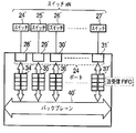
- the block diagram which shows the structure of the network switch which concerns on one Embodiment of this invention.
- the block diagram which shows the structure of the network switch which concerns on one Embodiment of this invention.
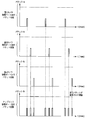
- Explanatory drawing which shows an example of the data transmission timing in the network switch which concerns on one Embodiment of this invention.
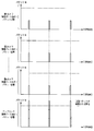
- Explanatory drawing which shows an example of the data transmission timing in case the transmission packet in the network switch which concerns on one Embodiment of this invention is discarded.
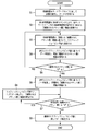
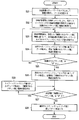
- 6 is a flowchart showing an example of a traffic shaping control process in the image recording system according to the embodiment of the present invention.
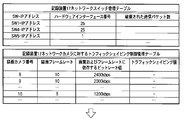
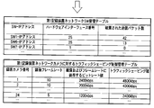
- FIG. 4 is an explanatory diagram illustrating a state in which a transmission packet is prevented from being discarded by traffic shaping control in the network management table and the traffic shaping control management table held in the recording apparatus of the image recording system according to the embodiment of the present invention.
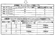
- FIG. 4 is an explanatory diagram illustrating a state in which a transmission packet is prevented from being discarded by traffic shaping control in the network management table and the traffic shaping control management table held in the recording apparatus of the image recording system according to the embodiment of the present invention.
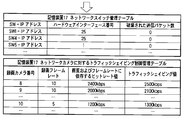
- FIG. 4 is an explanatory diagram illustrating a state in which a transmission packet is prevented from being discarded by traffic shaping control in the network management table and the traffic shaping control management table held in the recording apparatus of the image recording system according to the embodiment of the present invention.
- the transmission packet is discarded by the stepwise traffic shaping control.
- Explanatory drawing which shows a mode that it avoided that.
- the transmission packet is discarded by the stepwise traffic shaping control.
- Explanatory drawing which shows a mode that it avoided that.
- Explanatory drawing which shows a mode that the transmission packet was avoided by traffic shaping control in the image recording system which concerns on one Embodiment of this invention.
- Explanatory drawing which shows a mode that the transmission packet was avoided by traffic shaping control in the image recording system which concerns on one Embodiment of this invention.
- 7 is a flowchart showing an example of a traffic shaping control process when automatically selecting a network switch to be monitored in traffic shaping control according to another embodiment of the present invention.
- the block diagram which shows an example of a structure of the image recording system which concerns on other one Embodiment of this invention. Description showing a state in which a transmission packet is avoided from being discarded by traffic shaping control in a network management table and a traffic shaping control management table held in a management apparatus of an image recording system according to another embodiment of the present invention.
- Figure. 9 is a flowchart showing an example of a traffic shaping control process in an image recording system according to another embodiment of the present invention.
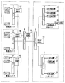
- FIG. 1 is a block diagram illustrating an example of a configuration of an image recording system according to an embodiment of the present invention
- FIGS. 2A and 2B are blocks illustrating a configuration of a network switch of the image recording system according to an embodiment of the present invention
- FIG. 3 is an explanatory diagram showing an example of data transmission timing in the network switch of the image recording system according to the embodiment of the present invention
- FIG. 4 is a diagram of the network switch of the image recording system according to the embodiment of the present invention. It is explanatory drawing which shows an example of the data transmission timing in case a transmission packet is discarded.
- the image recording system has, as an example, an edge switch 1 and a plurality of cameras 8, 9, 10 connected thereto in the first monitoring area.
- the edge switch 2 In the second monitoring area, the edge switch 2 and a plurality of cameras 11, 12, 13 connected thereto are provided.
- the edge switch 3 In the third monitoring area, the edge switch 3 and a plurality of cameras connected thereto are provided. Cameras 14, 15 and 16 are provided.
- this image recording system has an edge switch 6, a plurality of recording devices 17, 18, 19 and a management device 20 connected thereto in the recording area. Further, this image recording system has an edge switch 7 and a plurality of display devices 21, 22, and 23 connected thereto in the monitor area. These monitoring area, recording area, and monitoring area are connected via a center switch 4 and a center switch 5.
- At least the edge switch 1, the center switch 4, and the center switch 5 have SNMP (Simple Network Management Protocol) processing units 64, 65, and 66, respectively.
- at least the recording device 17 has an SNMP management unit 67.
- the present invention is not limited to this, and the edge switches 2, 3, 7 may also have SNMP processing units, and the recording devices 18, 19 may also have SNMP management units.
- This SNMP management unit has an SNMP manager (NMS: Network Management Station) function, and grasps the state of network devices in order to control network traffic and maintain stable communication quality. Further, the SNMP processing unit has an SNMP agent function, and holds management information called MIB (Management Information Base). In this MIB, information related to the hardware interface possessed by the device is managed in a portion called an interface group. As one piece of the management information, there is information indicating “ifOutDiscard: number of discarded transmission packets”.
- the recording devices 17, 18, and 19 cameras 8,... 16 connected to the monitoring area are registered, and connected to the corresponding cameras via a network, and image data is recorded at a pre-registered frame rate. Is acquired and an image is recorded.
- the management device 20 manages information such as the IP addresses of the cameras 8,..., 16 and the recording devices 17, 18, and 19 and the display device of the entire system in a database and performs fault monitoring.
- the recording device 17 records the images of the cameras 8 to 10
- the recording device 18 records the images of the cameras 11 to 13
- the recording device 19 records the images of the cameras 14 to 16.
- the display devices 21, 22, and 23 in the monitor area are connected to a target camera via a network, acquire a live image, and display the image on the display unit of the own device. Also, when confirming the recorded image of an arbitrary camera, specify “camera name etc.”, “recorded image date / time”, “recorded image playback control”, etc., and connect to the target recording device via the network. And the recorded image is displayed on the display unit of the own device.
- FIG. 2A it is assumed that the cameras 24... 27 corresponding to the cameras 8... 16 described above are connected to the physical ports 28 to 31 of the edge switches 1, 2 and 3.
- the physical port 32 and the physical port 33 are used as uplink ports to the center switch 4 which is an adjacent network switch.
- the physical port 28 to the physical port 31 are 24 ports in total
- the physical port 32 and the physical port 33 are 2 ports in total. Packet data input / output from each physical port is exchanged via the input / output buffers 34 to 39 and the backplane 40.
- the backplane 40 in the normal network switch has the capability of enabling transfer at a transfer rate higher than the total transfer rate of the data amount input / output from the physical port.
- the physical ports 28 'to 31' of the center switch 4 are connected to the uplink ports of the edge switches 1,... 3 described above (other edge switches may be connected). Shall be.
- the physical ports 28 'to 31' are a total of 24 ports. Packet data input / output from each physical port is exchanged via the input / output buffers 34'-37 'and the backplane 40'. If the transfer rate of the physical ports 28 'to 31' is defined as 1000 Mbps, at least 48 Gbps transmission rate is required for the backplane. Therefore, the transmission rate for the backplane 40 ′ in the normal network switch has the capability of enabling transfer at a transfer rate higher than the total transfer rate of the data amount input from the physical port.
- the transmission packet is transferred from the uplink of the physical port 33 to the adjacent network switch. Indicates the state of the number. If the packet transfer timing of data input from the physical ports 28 to 31 is different, the packet data output from the uplink of the physical port 33 is not reached because the number of packets has not reached the threshold for discarding the number of transmitted packets. Are transferred without being destroyed.
- FIG. 4 shows the number of packets transferred from the uplink of the physical port 33 to the adjacent network switch when data from the cameras connected to the physical ports 28 to 31 are output at the same timing. Indicates the state.
- the packet transfer timings of data input from the physical ports 28 to 31 overlap the packet data output from the uplink of the physical port 33 is discarded if it exceeds the threshold of the number of packets that can be transmitted. It becomes.
- This phenomenon is because the transmission rate of the backplane 40 is larger than the transfer rate obtained by adding up the amount of data inputted / outputted from each physical port. It will occur as a difference. For this reason, input / output buffers 34 to 39 are provided for each physical port, and the packet data flowing from the backplane 40 in a burst (large amount) by this buffer is output from the physical port while adjusting the output timing. I'm in charge.
- Example 1 Next, the traffic control in the image recording system according to the embodiment of the present invention will be described with reference to the flowchart of FIG. 5, the management tables of FIGS. 6A to 6C and FIGS. 7A to 7B, and the data transmission timings of FIGS. This will be described in detail below.
- the traffic control in the image recording system according to the embodiment of the present invention is based on the traffic shaping value according to the “number of discarded transmission packets” information acquired by the SNMP management unit 67. Is controlled step by step. 6A to 6C and FIGS. 7A to 7B sequentially show the results of a series of stepwise controls for one traffic process, and FIG. 6C is assumed to lead to FIG. 7A.
- the recording device 17 holds a network switch management table as shown in FIGS. 6A to 6C.
- the purpose of this management table is “the number of discarded transmission packets” at the corresponding physical port (hardware interface number) in the network switch of the IP address shown in the management table by the SNMP management unit 67 installed in the recording device 17. Is to manage.
- the network switch information may be added or updated by detecting the topology or device on the network.
- the recording device 17 holds a traffic shaping control management table for the network camera as shown in FIGS. 6A to 6C.
- the purpose of this management table is to perform traffic shaping on the data sent from the camera by registering “recording frame rate” and “bit rate value depending on image quality and frame rate” determined for each camera. It is.
- the recording device 17 requests an image from the network camera, the network camera transfers image data to the recording device 17, and the recording device 17 receives the image data and records it at the set frame rate (S1). ).
- the SNMP management unit 67 acquires the “number of discarded packets” information from the MIB held by the SNMP processing unit of each network switch by the SNMP command, and updates the network switch management table (S2).
- the SNMP management unit 67 determines a traffic shaping value for the camera based on the acquired “number of discarded packets” information, and updates the traffic shaping control management table (S3).
- the traffic shaping value is always the limit value (lower limit) of the “bit rate value depending on image quality and frame rate” for the network camera. These conditions are the same when the traffic shaping value is set in the subsequent steps.
- the camera transfers the data using the traffic shaping value determined in S3 as the transfer rate, acquires the “number of discarded packets” information again, and updates the network switch management table (S4).
- the previous value is determined to be the optimum value of the traffic shaping value (transfer rate) for the camera, and the traffic shaping control management table is updated.
- the camera transfers data with the most recent traffic shaping value as the optimum transfer rate.
- Traffic shaping is performed with “2500 kbps”.
- the number of discarded transmission packets of SW1 is “0”, and it is determined that all transmission packets have been transmitted. Thereafter, the data is transferred at a transfer rate of 2500 kbps.
- the switch 1 has been described as an example, but the SNMP processing unit is also provided in the switch 2 and the switch 3, and at the same time, the “number of discarded transmission packets” is acquired and connected to each switch. It is desirable that traffic shaping is performed on the cameras, and it is possible to operate the system so as to control network traffic and maintain stable communication quality in the entire network monitoring system.
- S5 and S7 are “0” here, it is also possible to use a value determined by the user or a value derived from traffic information as a threshold value and whether or not it is a predetermined threshold value or less.
- the effects of these network traffic controls are transmitted from the cameras connected to the physical ports 28 to 31 of the edge switch 1 (SW1 in the table) as shown in the management table of FIG. 8A and the management table of FIG. 8B.
- This can be understood from the reduction in the number of packets when traffic shaping is applied to data. That is, as shown in the improved management table of FIG. 8B, the packet data output from the uplink of the physical port 33 is output at the same timing as the data from the camera by network traffic control (traffic shaping processing). Even in such a case, stable network communication can be realized with an optimum communication amount without exceeding the threshold of the number of packets that can be transmitted.
- FIG. 9 is a flowchart illustrating an example of a traffic shaping control process when a network switch to be monitored is automatically selected. This embodiment differs from the first embodiment described with reference to the flowchart of FIG. 5 in S12 and S13, and the other points are the same and will be omitted as much as possible.
- the recording device 17 requests an image from the network camera and receives data (S11: corresponding to S1 in FIG. 5).
- the SNMP management unit 67 measures the input data amount on the input side and the output data amount on the uplink port side of each switch 1, 2, 3, 4, 5, 6, 7, etc., and determines the relationship.
- the network switch management table and the traffic shaping control management table are updated with the network switch whose input data amount is larger than the output data amount being monitored (S12).
- the SNMP management unit 67 may initially measure the amount of data and add it. However, all the switch information is acquired in advance. When the input data amount is less than or equal to the output data amount, it may be excluded from the monitoring target.
- the SNMP management unit 67 acquires the “number of discarded packets” information from the MIB held by the SNMP processing unit of the network switch to be monitored by the SNMP command (S13). ). Thereafter, the same processing as that of the first embodiment described in FIG. 5 is performed (S14 to S20: corresponding to S3 to 9 in FIG. 5).
- the network switch to be monitored since only the network switch to be monitored can be monitored, less information is managed, and the network can be managed more simply and easily.
- Example 3 The case where traffic shaping is performed by the SNMP management unit 67 installed in the recording devices 17, 18, and 19 has been described above. However, as shown in FIG. 10, an SNMP management unit 70 is installed in the management device 20, holds a network switch management table as shown in FIG. Even if the operation for performing traffic shaping is adopted, similarly, it becomes possible to avoid the discard of the transmission packet and perform the smooth network communication.
- the traffic shaping control in this case will be described below.
- the edge switch 1, the edge switch 2, the edge switch 3, the center switch 4, and the center switch 5 have SNMP (Simple Network Management Protocol) processing units 64, 65, and 66, respectively.
- the management device 20 has an SNMP management unit 70.
- the SNMP management unit 70 of the management apparatus 20 has the network switch management table shown in FIG. 11, manages information such as the IP address, hardware interface number, and the number of discarded transmission packets of each network switch. A state in which the management apparatus collectively manages the traffic shaping control management table of the apparatus will be described.
- the SNMP management unit 70 of the management device 20 has a network switch management table for managing each network switch on the network shown in FIG. 11, and the recording devices 17 to 19 are networks managed by each recording device. Each has a traffic shaping control management table for the camera.
- the SNMP management unit 70 of the management apparatus 20 acquires “discarded packet number” information from the MIB held by the SNMP processing unit of each network switch by the SNMP command, and “discarded packet number” in the network switch management table. Information is updated (S22).
- the SNMP management unit 70 determines the traffic shaping value for the network camera managed by the recording devices 17 to 19 according to the “number of discarded transmission packets” information of each network switch, and updates each traffic shaping control management table (S23).
- the recording devices 17 to 19 control each network camera to transfer data with the determined and updated traffic shaping values (S24).
- the SNMP management unit 70 of the management apparatus 20 acquires the “number of discarded packets” information of each network switch again, updates the network switch management table, and determines whether or not the number of discarded transmission packets is “0”. (S25). If the “number of discarded packets” is not “0” (NO), the process of S23 is performed again, and the process is repeated until the “number of discarded packets” becomes “0”. On the other hand, if the “number of discarded packets” is “0” (YES), the recording devices 17 to 19 transfer data to the respective network cameras with the determined and updated traffic shaping values.
- the network switch management table is updated by periodically acquiring the “number of discarded packets” information (S26).
- the SNMP management unit 70 of the management device 20 determines that there is still a margin in the transfer rate, slightly increases the traffic shaping value for each camera, updates the traffic shaping management tables of the recording devices 17 to 19 respectively, and records them.
- the devices 17 to 19 control each network camera to transfer the data with the determined and updated traffic shaping values, and acquire the “number of discarded packets” information again (S28). Repeat until “number of packets received” is no longer “0”.
- the range for increasing the traffic shaping value is an arbitrary value.
- the immediately preceding traffic shaping value is determined to be the optimum value of the traffic shaping value (transfer rate) for each camera, and the SNMP management of the management apparatus 20 is performed.
- the unit 70 updates the traffic shaping control management tables of the recording devices 17 to 19, and the recording devices 17 to 19 determine and update the respective traffic cameras with the most recent traffic shaping value as the optimum transfer rate. Control is performed so as to transfer data with the traffic shaping value thus set (S29).
- each recording device has a traffic shaping control management table.
- the management device may collectively manage the traffic shaping control management table.
- the SNMP management unit 70 of the management apparatus 20 includes a network switch management table for managing each network switch on the network illustrated in FIG. 11 and a traffic shaping control management table for the network camera managed by each recording apparatus. This is achieved by changing the control body of S23, S24, S26, S28, and S29 in the flowchart shown in FIG. 12 from the recording devices 17 to 19 to the management device 20.
- the network switches to be monitored may be limited as in the second embodiment.
- the management device can collectively manage the table. This makes it possible to manage the network more easily and uniformly.
Landscapes
- Engineering & Computer Science (AREA)
- Multimedia (AREA)
- Signal Processing (AREA)
- Databases & Information Systems (AREA)
- Two-Way Televisions, Distribution Of Moving Picture Or The Like (AREA)
- Data Exchanges In Wide-Area Networks (AREA)
Abstract
送信パケットが破棄されることがない通信速度で通信を行うデータ記録システム、データ記録装置、管理装置および通信量制御方法を提供する。 データ送出装置8とこれにネットワークを介して接続されるデータ記録装置17を有するデータ記録システムであって、データ記録装置17またはネットワーク上の装置20に搭載したSNMP管理機能を用いて、データ送出装置とデータ記録装置との間の通信におけるパケット破棄情報を取得し、該パケット破棄情報に基づいてデータ送出装置とデータ記録装置との間の通信データ量を制御する。
Description
本発明は、ネットワーク上の装置間の通信量を制御するデータ記録システムに関し、特に、SNMP管理機能を用いて取得した「破棄された送信パケット数」情報に基づいて通信量を制御するデータ記録システム、データ記録装置、管理装置および通信量制御方法に関する。
近年、例えば、監視カメラおよび画像記録装置、ネットワークスイッチ、画像表示装置を備え、画像監視するとともに画像データを画像記録装置に記録する画像監視システム等の画像記録システムが運用されている。
特許文献1は、ネットワーク上の画像信号を蓄積する機能をもった画像配信システムであって、特に、画像の配信状況を表示する働きを開示している。
特許文献1:特開2008-148347号公報
しかしながら、上記したネットワークを用いた映像記録システムにおいては、一定以上の通信量の通信を行うと、例えば、データ伝送を担うネットワークスイッチ部にて送信パケットの破棄が発生してしまう場合がある。また、上述した特許文献1においても、この送信パケットの破棄についてどのように対応するべきかが記載されていない。
しかしながら、上記したネットワークを用いた映像記録システムにおいては、一定以上の通信量の通信を行うと、例えば、データ伝送を担うネットワークスイッチ部にて送信パケットの破棄が発生してしまう場合がある。また、上述した特許文献1においても、この送信パケットの破棄についてどのように対応するべきかが記載されていない。
本発明は、送信パケットが破棄されることがない通信速度で通信を行う画像記録システム、画像記録装置、管理装置および通信量制御方法を提供することを目的とする。
上記課題を解決するために本発明のデータ記録システムは、データ送出装置と、前記データ送出装置にネットワークを介して接続されるデータ記録装置を有するデータ記録システムであって、 前記データ記録装置または前記ネットワーク上の装置に搭載したSNMP管理機能を用いて、前記データ送出装置と前記データ記録装置との間の通信におけるパケット破棄情報を取得し、該パケット破棄情報に基づいて前記データ送出装置と前記データ記録装置との間の通信量を制御することを特徴とする。
また、上記データ記録システムは、さらに、前記データ送出装置が接続され、前記データ送出装置から入力されたデータを集束して出力するネットワークスイッチを有し、前記データ記録装置または前記ネットワーク上の装置はSNMP管理機能を用いて、前記ネットワークスイッチのパケット破棄情報を取得し、該パケット破棄情報に基づいて前記データ送出装置の送出データ量を制御することを特徴とする。
また、上記データ記録システムは、前記前記データ記録装置または前記ネットワーク上の装置は、取得した前記パケット破棄情報が0または所定値以下になるまで制御することを特徴とする。
また、上記データ記録システムは、前記データ記録装置または前記ネットワーク上の装置は、取得した前記パケット破棄情報が所定期間0である場合、前記データ送出装置の送出データ量を所定値ずつ多くし、前記パケット破棄情報が0を超えたら、直前の送出データ量の値を前記データ送出装置の送出データ量として制御することを特徴とする。
また、上記データ記録システムは、前記データ記録装置または前記ネットワーク上の装置は、前記ネットワークスイッチの入力データ量および出力データ量情報を取得し、出力データ量が入力データ量より少ないネットワークスイッチを前記パケット破棄情報の取得対象とすることを特徴とする。
また、上記課題を解決するために本発明のデータ記録装置は、データ送出装置とネットワークを介して通信を行うデータ記録装置であって、SNMP管理機能を搭載し、前記SNMP管理機能を用いて前記データ装置との間の通信におけるパケット破棄情報を取得し、該パケット破棄情報に基づいて前記データ送出装置との間の通信量を制御する。
また、上記課題を解決するために本発明の管理装置は、データ送出装置とデータ記録装置の間のネットワーク上の通信量を管理する管理装置であって、前記ネットワーク上に設けられることで、前記データ送出装置と前記データ記録装置との間の通信におけるパケット破棄情報をSNMP管理機能を用いて取得し、該パケット破棄情報に基づいて前記データ送出装置と前記データ記録装置との間の通信量を制御することを特徴とする。
また、上記課題を解決するために本発明の通信データ量制御方法は、データ送出装置とデータ記録装置との間のネットワーク上の通信量を制御する通信量制御方法であって、前記データ送出装置と前記データ記録装置との間の通信におけるパケット破棄情報をSNMP管理機能を用いて取得し、前記取得したパケット破棄情報に基づいて、前記データ送出装置と前記データ記録装置との間の通信データ量を制御することを特徴とする。
通信ネットワークで用いられるSNMP管理機能を利用して装置間の通信における「破棄された送信パケット数」情報を取得し、この情報に基づき段階的に通信量を調整してこの「破棄された送信パケット数」をゼロに近づけることで、ユーザが手動で調整することなく自動的に最適の通信量による通信を実現する。
以下、この発明の実施の形態について図面を参照して詳細に説明する。図1は、本発明の一実施形態に係る画像記録システムの構成の一例を示すブロック図、図2Aおよび図2Bは、本発明の一実施形態に係る画像記録システムのネットワークスイッチの構成を示すブロック図、図3は、本発明の一実施形態に係る画像記録システムのネットワークスイッチにおけるデータ送出タイミングの一例を示す説明図、図4は、本発明の一実施形態に係る画像記録システムのネットワークスイッチにおける送信パケットが破棄さる場合のデータ送出タイミングの一例を示す説明図である。
本発明の一実施形態に係る画像記録システムは、図1に示す様に、一例として、第1監視エリアにおいて、エッジスイッチ1と、これに接続される複数台のカメラ8、9、10を有し、第2監視エリアにおいて、エッジスイッチ2と、これに接続される複数台のカメラ11、12、13を有し、第3監視エリアにおいて、エッジスイッチ3と、これに接続される複数台のカメラ14、15、16を有する。
さらに、この画像記録システムは、記録エリアにおいて、エッジスイッチ6と、これに接続される複数台の記録装置17、18、19および管理装置20を有する。さらに、この画像記録システムは、モニタエリアにおいて、エッジスイッチ7と、これに接続される複数台の表示装置21、22、23を有する。また、これらの監視エリア、記録エリア、モニタエリアは、センタスイッチ4およびセンタスイッチ5を介して接続される。
また、少なくともエッジスイッチ1、センタスイッチ4、センタスイッチ5は、内部にSNMP(Simple Network Management Protocol)処理部64、65、66をそれぞれ有している。また、少なくとも記録装置17は、SNMP管理部67を有している。しかし、これに限らず、エッジスイッチ2,3,7もSNMP処理部を有していてもよく、また、記録装置18,19もSNMP管理部を有していても良い。
このSNMP管理部は、SNMPマネージャ(NMS:Network Management Station)機能を有しており、ネットワークトラフィックを制御し、通信品質を安定的に保つために、ネットワーク機器の状態を把握するものである。また、SNMP処理部は、SNMPエージェント機能を有しており、MIB(Management Information Base)という管理情報を保持している。このMIBには、インタフェースグループという部分に、機器が保有するハードウェアインターフェースに関係する情報が管理されている。その管理情報のひとつに「ifOutDiscard:破棄された送信パケット数」を示す情報が存在する。
記録エリアの記録装置17,18,19は、監視エリアに接続されているカメラ8,…16が登録されており、該当するカメラにネットワークを介して接続し、予め登録されたフレームレートにより画像データを取得し、画像を記録するものである。また、管理装置20はシステム全体のカメラ8,…16および記録装置17,18,19、表示装置のIPアドレス等の情報をデータベースに管理するとともに障害監視などを行うものである。ここでは、記録装置17はカメラ8~10の画像、記録装置18はカメラ11~13の画像、記録装置19はカメラ14~16の画像を記録することとする。
モニタエリアの表示装置21,22,23は、対象のカメラにネットワークを介して接続し、ライブ画像を取得して、自機の表示部に画像を表示するものである。また、任意のカメラの記録画像を確認する場合は、「カメラ名称等」および「記録画像日時」、「記録画像再生制御」などを指定して対象記録装置にネットワークを介して接続し、記録画像を取得して、自機の表示部に記録画像を表示するものである。
次に、図2Aおよび図2Bを用いて、特に、上述したエッジスイッチ1,2,3およびセンタスイッチ4の内部の構成を説明する。図2Aにおいて、エッジスイッチ1,2,3の物理ポート28~物理ポート31には、上述したカメラ8,…16が対応するカメラ24…カメラ27が接続されるものとする。物理ポート32および物理ポート33は隣接するネットワークスイッチであるセンタスイッチ4へのアップリンクポートとして使用するものとする。なお、ここでは、物理ポート28~物理ポート31を計24ポート、物理ポート32および物理ポート33を計2ポートとする。各物理ポートから入出力されるパケットデータは、入出力バッファ34~39およびバックプレーン40を介してやり取りさわれる。今、物理ポート32および33の転送レートを1000Mbps、物理ポート28~31の転送レートを100Mbpsと定義すると、バックプレーンには少なくとも8.8Gbps伝送レートが要求される。そのため、通常ネットワークスイッチにおけるバックプレーン40に対する伝送レートは物理ポートから入出力されるデータ量を合計した転送レート以上での転送を可能とする能力を有する。
また、図2Bにおいて、センタスイッチ4の物理ポート28´~物理ポート31´には、上述したエッジスイッチ1,…3(さらに他のエッジスイッチが接続されていても良い)のアップリンクポートが接続されるものとする。なお、ここでは、物理ポート28´~物理ポート31´を計24ポートとする。各物理ポートから入出力されるパケットデータは、入出力バッファ34´~37´およびバックプレーン40´を介してやり取りされる。物理ポート28´~31´の転送レートを1000Mbpsと定義すると、バックプレーンには少なくとも48Gbps伝送レートが要求される。そのため、通常ネットワークスイッチにおけるバックプレーン40´に対する伝送レートは物理ポートから入力されるデータ量を合計した転送レート以上での転送を可能とする能力を有する。
ここで、図3において、物理ポート28~31に接続されているカメラからのデータが任意のタイミングにて出力された場合の、物理ポート33のアップリンクから隣接するネットワークスイッチに転送される送信パケット数の状態を示す。物理ポート28~31から入力されるデータのパケット転送タイミングが異なっている場合、送信パケット数が破棄される閾値にパケット数が到達していないため、物理ポート33のアップリンクから出力されるパケットデータは破棄されることなく転送される。
なお、センタスイッチ4においても同様である。
一方、図4は、物理ポート28~31に接続されているカメラからのデータが同一のタイミングにて出力された場合の、物理ポート33のアップリンクから隣接するネットワークスイッチに転送されるパケット数の状態を示す。物理ポート28~31から入力されるデータのパケット転送タイミングが重なった場合、物理ポート33のアップリンクから出力されるパケットデータは、送信可能なパケット数の閾値を超えたものについては破棄されることとなる。この現象は、バックプレーン40の伝送レートが各物理ポートから入出力されるデータ量を合計した転送レートより大きいため、その転送レートから、例えば物理ポート33の転送レート1000Mbpsにダウンレート変換する際に差分として生じてしまうものである。そのため、各物理ポートには入出力バッファ34~39を設けられ、このバッファによってバースト的(大量)にバックプレーン40から流入されるパケットデータを、出力タイミングを調整しながら物理ポートから出力する役目を担っている。
ただし、入出力バッファには物理的なサイズの限界がつきまとい、入出力バッファに大量にパケットが入力された場合には、バッファの限界量を超えた量のパケットについては破棄することとなってしまう。この様な送信パケットの破棄が生じると、破棄されたパケットを再度送信し直すこととなり、実質的な通信速度が低下し、さらなるネットワークのトラフィックを生むこととなってしまう。
(実施例1)
次に、本発明の一実施形態に係る画像記録システムにおけるトラフィック制御を図5のフローチャート、図6A~図6C、図7A~図7Bの管理テーブルおよび図8A、図8Bのデータ送出タイミングの説明図を用いて以下に詳細に説明する。本発明の一実施形態に係る画像記録システムにおけるトラフィック制御は、以下に述べる様に、SNMP管理部67が取得した「破棄された送信パケット数」情報に応じたトラフィックシェイピング値に基づいて、通信量を段階的に制御するものである。なお、図6A~図6Cと図7A~図7Bは、一トラフィック処理の一連の段階的制御の結果を順々に示すものであり、図6Cは、図7Aへと繋がるものとする。
次に、本発明の一実施形態に係る画像記録システムにおけるトラフィック制御を図5のフローチャート、図6A~図6C、図7A~図7Bの管理テーブルおよび図8A、図8Bのデータ送出タイミングの説明図を用いて以下に詳細に説明する。本発明の一実施形態に係る画像記録システムにおけるトラフィック制御は、以下に述べる様に、SNMP管理部67が取得した「破棄された送信パケット数」情報に応じたトラフィックシェイピング値に基づいて、通信量を段階的に制御するものである。なお、図6A~図6Cと図7A~図7Bは、一トラフィック処理の一連の段階的制御の結果を順々に示すものであり、図6Cは、図7Aへと繋がるものとする。
ここで、記録装置17では、図6A~図6Cに示す様なネットワークスイッチ管理テーブルを保持するものとする。この管理テーブルの目的は、記録装置17に搭載するSNMP管理部67によって、管理テーブルに示すIPアドレスのネットワークスイッチにおける、対応する物理ポート(ハードウェアインターフェース番号)での「破棄された送信パケット数」を管理することである。この表においては、エッジスイッチ1(表中のSW1)の「IPアドレス」およびアップリンク物理ポート「ハードウェアインターフェース番号:25」、同様にセンタスイッチ4(表中のSW4)の「IPアドレス」およびアップリンク物理ポート「ハードウェアインターフェース番号:25」、センタスイッチ5(表中のSW5)の「IPアドレス」およびアップリンク物理ポート「ハードウェアインターフェース番号:1」等を登録しておくものとする。または、ネットワーク上のトポロジや機器を検出して、ネットワークスイッチの情報を追加・更新していく様にしても良い。
また同時に、記録装置17では、図6A~図6Cに示す様なネットワークカメラに対するトラフィックシェイピング制御管理テーブルを保持するものとする。この管理テーブルの目的は、カメラ毎に定めた「録画フレームレート」および「画質およびフレームレートに依存するビットレート値」を登録することにより、カメラから送出されるデータに対してトラフィックシェイピングを行うことである。
まず、記録装置17はネットワークカメラに対して画像を要求し、ネットワークカメラは記録装置17に向けて画像データを転送し、記録装置17は画像データを受信し、設定したフレームレートで記録する(S1)。SNMP管理部67は、SNMPコマンドにより、各ネットワークスイッチのSNMP処理部が保有するMIBから「破棄されたパケット数」情報を取得し、ネットワークスイッチ管理テーブルを更新する(S2)。SNMP管理部67は、取得した「破棄されたパケット数」情報に基づいて、カメラに対するトラフィックシェイピング値を決定し、トラフィックシェイピング制御管理テーブルを更新する(S3)。ここで「破棄されたパケット数」情報に基づいてとは、例えば、「破棄されたパケット数」が多ければトラフィックシェイピング値の縮減幅を大きく、少なければ縮減幅を小さくするといったことである。ただし、このとき、トラフィックシェイピング値は必ずネットワークカメラに対する「画質およびフレームレートに依存するビットレート値」を限度値(下限)とする。これらの条件は、以降のステップにおいてトラフィックシェイピング値を設定する際も同様とする。S3で決定したトラフィックシェイピング値を転送レートとしてカメラはデータ転送し、再度「破棄されたパケット数」情報を取得してネットワークスイッチ管理テーブルを更新する(S4)。
次に、S4で取得した「破棄されたパケット数」が“0”か否かを判断し、“0”でない場合(NO)は再度S3の処理を実行し、「破棄されたパケット数」が“0”になるまで繰り返す。一方、「破棄されたパケット数」が“0”であった場合(YES)、決定したトラフィックシェイピング値に基づいてカメラはデータ転送し、定期的に「破棄されたパケット数」情報を取得してネットワークスイッチ管理テーブルを更新する(S6)。
ここで、効率的なデータ転送のため、さらに、S6で取得した「破棄されたパケット数」が所定期間“0”が継続したか否かを判断し(S7)、“0”が継続した場合(YES)、まだ転送レートに余裕があると判断してカメラに対するトラフィックシェイピング値を少し上げてデータ転送し、「破棄されたパケット数」情報を取得し(S8)、“0”でなくなるまで繰り返す。このとき、上げるトラフィックシェイピング値の幅は任意の値とする。一方、「破棄されたパケット数」が“0”でなくなった場合(NO)、直前の値がカメラに対するトラフィックシェイピング値(転送レート)の最適値と判断し、トラフィックシェイピング制御管理テーブルを更新し、直前のトラフィックシェイピング値を最適な転送レートとしてカメラはデータ転送する。
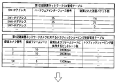
ここで、破棄されたパケット数の多少によってトラフィックシェイピング値を決定する様子を説明する。例えば、図6Bにおいて、SW(スイッチ)1の破棄された送信パケット数が“118”であるとき、トラフィックシェイピング値を“4800kbps”としてトラフィックシェイピングを行う。その結果、図6Cに示す様に、SW1の破棄された送信パケット数は“42”となり、“0”にはならなかったので、さらにこの“42”に応じたトラフィックシェイピング値を-2000した“2800kbps”としてトラフィックシェイピングを行う。その結果、図7Aに示す様に、SW1の破棄された送信パケット数は“9”となり、 “0”にはならなかったので、またさらにこの“9”に応じたトラフィックシェイピング値を-300した“2500kbps”としてトラフィックシェイピングを行う。その結果、図7Bに示す様に、SW1の破棄された送信パケット数は“0”となり、全ての送信パケットが送信されたと判断し、以後転送レートを2500kbpsとしてデータを転送する。
なお、ここでは、スイッチ1を取り上げて説明したが、スイッチ2やスイッチ3にもSNMP処理部が設けられていて、同時に同様に「破棄された送信パケット数」を取得し、各スイッチに接続されたカメラに対してトラフィックシェイピングが行われることが望ましいく、ネットワーク監視システム全体において、ネットワークトラフィックを制御し、通信品質を安定的に保つ様システム運用することが可能となる。
また、ここではS5およびS7の判断を“0”か否かとしたが、ユーザが定めた値またはトラフィック情報から導き出された値を閾値として、所定の閾値以下か否かとしても良い。
また、センタスイッチ4においても、接続されたエッジスイッチ1~3から入力されるデータに対して、同様にトラフィックシェイピングを行う形態も考えられる。
これらのネットワークトラフィック制御の効果は、図8Aの管理テーブルと図8Bの管理テーブルが示す様に、エッジスイッチ1(表中のSW1)の物理ポート28~31に接続されているカメラからの送出されるデータに対してトラフィックシェイピングを適用した場合のパケット数の減少により理解できる。すなわち、改善された図8Bの管理テーブルが示すように、ネットワークトラフィック制御(トラフィックシェイピング処理)により、物理ポート33のアップリンクから出力されるパケットデータは、カメラからのデータが同一のタイミングにて出力された場合においても送信可能なパケット数の閾値を超えることなく、最適の通信量により安定したネットワーク通信を実現することができる。
これにより、送信パケットが破棄されることがない最適な転送レートによる画像記録システム、画像記録装置、管理装置および通信量制御方法を提供することができる。
(実施例2)
本発明の他の実施の形態として、監視対象とするネットワークスイッチの選択の様子を、図9を用いて詳細に説明する。図9は、監視対象となるネットワークスイッチを自動選択する場合のトラフィックシェイピング制御の工程の一例を示すフローチャートである。図5のフローチャートを用いて説明した実施例1とは、S12およびS13において異なり、その他の点は同様であるためなるべく省略して説明する。
本発明の他の実施の形態として、監視対象とするネットワークスイッチの選択の様子を、図9を用いて詳細に説明する。図9は、監視対象となるネットワークスイッチを自動選択する場合のトラフィックシェイピング制御の工程の一例を示すフローチャートである。図5のフローチャートを用いて説明した実施例1とは、S12およびS13において異なり、その他の点は同様であるためなるべく省略して説明する。
記録装置17はネットワークカメラに対して画像を要求し、データを受信する(S11:図5におけるS1に相当)。次に、SNMP管理部67は、各スイッチ1,2,3,4,5,6,7等の入力側の入力データ量とアップリンクポート側の出力データ量を計測してその関係を判断し、入力データ量が出力データ量より大きいネットワークスイッチを監視対象としてネットワークスイッチ管理テーブルおよびトラフィックシェイピング制御管理テーブルを更新する(S12)。ここで、どのスイッチを監視対象のスイッチとするかについては、最初にSNMP管理部67がデータ量を計測して追加していってもよいが、予め、全てのスイッチ情報を取得しておいて、入力データ量が出力データ量以下である場合に監視対象から外す様にしても良い。S12で監視対象とするネットワークスイッチを決定したら、SNMP管理部67は、SNMPコマンドにより、監視対象としたネットワークスイッチのSNMP処理部が保有するMIBから「破棄されたパケット数」情報を取得する(S13)。以降は図5で説明した実施例1と同じ処理を行う(S14~S20:図5におけるS3~9に相当)。
本実施例によれば、監視対象とすべきネットワークスイッチのみを監視できるため、管理する情報が少なくて済み、よりシンプルにより容易にネットワークを管理することができる。
(実施例3)
以上、記録装置17,18,19に搭載するSNMP管理部67によってトラフィックシェイピングを行う場合を説明した。しかし、図10に示す様に、管理装置20にSNMP管理部70を搭載し、図11に示す様なネットワークスイッチ管理テーブルを保持し、記録装置17,18,19に対して管理装置20から各々トラフィックシェイピングを行う運用を採用しても、同様に、送信パケットの破棄を回避して円滑なネットワーク通信を行うことが可能となる。この場合のトラフィックシェイピング制御について、以下に説明する。
以上、記録装置17,18,19に搭載するSNMP管理部67によってトラフィックシェイピングを行う場合を説明した。しかし、図10に示す様に、管理装置20にSNMP管理部70を搭載し、図11に示す様なネットワークスイッチ管理テーブルを保持し、記録装置17,18,19に対して管理装置20から各々トラフィックシェイピングを行う運用を採用しても、同様に、送信パケットの破棄を回避して円滑なネットワーク通信を行うことが可能となる。この場合のトラフィックシェイピング制御について、以下に説明する。
エッジスイッチ1、エッジスイッチ2、エッジスイッチ3、センタスイッチ4、センタスイッチ5は、内部にSNMP(Simple Network Management Protocol)処理部64、65、66をそれぞれ有している。また、管理装置20は、SNMP管理部70を有している。管理装置20のSNMP管理部70では図11に示すネットワークスイッチ管理テーブルを有し、各ネットワークスイッチのIPアドレス、ハードウェアインターフェース番号、破棄された送信パケット数等の情報を管理し、さらに、各記録装置が有するトラフィックシェイピング制御管理テーブルも、管理装置が一括で管理する様子について説明する。
管理装置20のSNMP管理部70は、図11に記載のネットワーク上の各ネットワークスイッチを管理するためのネットワークスイッチ管理テーブルを有しており、記録装置17~19は、各記録装置が管轄するネットワークカメラに対するトラフィックシェイピング制御管理テーブルをそれぞれ有している。
管理装置20のSNMP管理部70は、SNMPコマンドにより、各ネットワークスイッチのSNMP処理部が保有するMIBから「破棄されたパケット数」情報を取得し、ネットワークスイッチ管理テーブルの「破棄されたパケット数」情報を更新する(S22)。SNMP管理部70は、それぞれのネットワークスイッチの「破棄された送信パケット数」情報に応じて、記録装置17~19の管轄するネットワークカメラに対するトラフィックシェイピング値を決定し、各トラフィックシェイピング制御管理テーブルを更新する(S23)。記録装置17~19は、それぞれの管轄するネットワークカメラに対し、それぞれ決定・更新されたトラフィックシェイピング値でデータ転送する様制御する(S24)。
そして、管理装置20のSNMP管理部70は再度各ネットワークスイッチの「破棄されたパケット数」情報を取得してネットワークスイッチ管理テーブルを更新し、破棄された送信パケット数が“0”か否か判断する(S25)。「破棄されたパケット数」が“0”でない場合(NO)は再度S23の処理を行い、「破棄されたパケット数」が“0”になるまで繰り返す。一方、「破棄されたパケット数」が“0”であった場合(YES)、記録装置17~19は、それぞれの管轄するネットワークカメラに対し、それぞれ決定・更新されたトラフィックシェイピング値でデータ転送する様制御し、定期的に「破棄されたパケット数」情報を取得してネットワークスイッチ管理テーブルを更新する(S26)。
ここで、効率的なデータ転送のため、さらに、S26で取得した「破棄されたパケット数」が所定期間“0”が継続したか否かを判断し(S27)、“0”が継続した場合(YES)、管理装置20のSNMP管理部70はまだ転送レートに余裕があると判断して各カメラに対するトラフィックシェイピング値を少し上げて記録装置17~19のトラフィックシェイピング管理テーブルをそれぞれ更新し、記録装置17~19は、それぞれの管轄するネットワークカメラに対し、それぞれ決定・更新されたトラフィックシェイピング値でデータ転送する様制御し、再度「破棄されたパケット数」情報を取得し(S28)、「破棄されたパケット数」が“0”でなくなるまで繰り返す。このとき、トラフィックシェイピング値の上げる幅は任意の値とする。一方、「破棄されたパケット数」が“0”でなくなった場合(NO)、直前のトラフィックシェイピング値が各カメラに対するトラフィックシェイピング値(転送レート)の最適値と判断し、管理装置20のSNMP管理部70は記録装置17~19のそれぞれのトラフィックシェイピング制御管理テーブルを更新し、記録装置17~19は直前のトラフィックシェイピング値を最適な転送レートとして、それぞれの管轄するカメラに対し、それぞれ決定・更新されたトラフィックシェイピング値でデータ転送する様制御する(S29)。
本実施例では、トラフィックシェイピング制御管理テーブルをそれぞれの記録装置が有する形態について説明したが、トラフィックシェイピング制御管理テーブルを管理装置が一括で有して管理しても良い。
この場合、管理装置20のSNMP管理部70は、図11に記載のネットワーク上の各ネットワークスイッチを管理するためのネットワークスイッチ管理テーブル、および、各記録装置が管轄するネットワークカメラに対するトラフィックシェイピング制御管理テーブルを有しており、図12に示すフローチャートのS23,S24,S26,S28,S29の制御主体が、記録装置17~19のそれぞれから管理装置20に変わることで達成される。
また、本実施例において、実施例2の様に監視対象とするネットワークスイッチを限定する様にしても良いことは言うまでもない。
以上に記載した実施例によれば、実施例1,2と同様に送信パケットの破棄を回避して円滑なネットワーク通信を行うことが可能となり、さらに、管理装置が一括してテーブル管理することで、より簡易に統一されたネットワーク管理が可能となる。
以上記載した様々な実施形態は複数同時に実施することが可能であり、これらの記載により、当業者は本発明を実現することができるが、更にこれらの実施形態の様々な変形例を思いつくことが当業者によって容易であり、発明的な能力をもたなくとも様々な実施形態へと適用することが可能である。従って、本発明は、開示された原理と新規な特徴に矛盾しない広範な範囲に及ぶものであり、上述した実施形態に限定されるものではない。
符号の説明
1,2,3…エッジスイッチ、4,5…センタスイッチ、6,7…エッジスイッチ、8,9,10,11,12,13,14,15,16,24,25,26,27…ネットワークカメラ、28,29,30,31…物理ポート、32,33…物理ポート(アップリンク)、34,35,36,37,38,39…入出力バッファ、40…バックプレーン、64,65,66,68,69…SNMP処理部、67,70…SNMP管理部。
1,2,3…エッジスイッチ、4,5…センタスイッチ、6,7…エッジスイッチ、8,9,10,11,12,13,14,15,16,24,25,26,27…ネットワークカメラ、28,29,30,31…物理ポート、32,33…物理ポート(アップリンク)、34,35,36,37,38,39…入出力バッファ、40…バックプレーン、64,65,66,68,69…SNMP処理部、67,70…SNMP管理部。
Claims (4)
- データ送出装置と、前記データ送出装置にネットワークを介して接続されるデータ記録装置を有するデータ記録システムであって、
前記データ記録装置または前記ネットワーク上の装置に搭載したSNMP管理機能を用いて、前記データ送出装置と前記データ記録装置との間の通信におけるパケット破棄情報を取得し、該パケット破棄情報に基づいて前記データ送出装置と前記データ記録装置との間の通信量を制御することを特徴とするデータ記録システム。 - データ送出装置とネットワークを介して通信を行うデータ記録装置であって、SNMP管理機能を搭載し、前記SNMP管理機能を用いて前記データ送出装置との間の通信におけるパケット破棄情報を取得し、該パケット破棄情報に基づいて前記データ送出装置との間の通信量を制御することを特徴とするデータ記録装置。
- データ送出装置とデータ記録装置の間のネットワーク上の通信量を管理する管理装置であって、
前記ネットワーク上に設けられることで、前記データ送出装置と前記データ記録装置との間の通信におけるパケット破棄情報をSNMP管理機能を用いて取得し、該パケット破棄情報に基づいて前記データ送出装置と前記データ記録装置との間の通信量を制御することを特徴とする管理装置。 - データ送出装置とデータ記録装置との間のネットワーク上の通信量を制御する通信量制御方法であって、
前記データ送出装置と前記データ記録装置との間の通信におけるパケット破棄情報をSNMP管理機能を用いて取得し、
前記取得したパケット破棄情報に基づいて、前記データ送出装置と前記データ記録装置との間の通信量を制御することを特徴とする通信量制御方法。
Applications Claiming Priority (2)
| Application Number | Priority Date | Filing Date | Title |
|---|---|---|---|
| JP2010-163385 | 2010-07-20 | ||
| JP2010163385A JP5593152B2 (ja) | 2010-07-20 | 2010-07-20 | データ記録システム、データ記録装置、管理装置および通信量制御方法 |
Publications (1)
| Publication Number | Publication Date |
|---|---|
| WO2012011301A1 true WO2012011301A1 (ja) | 2012-01-26 |
Family
ID=45496731
Family Applications (1)
| Application Number | Title | Priority Date | Filing Date |
|---|---|---|---|
| PCT/JP2011/056419 Ceased WO2012011301A1 (ja) | 2010-07-20 | 2011-03-17 | 映像記録システム、映像記録装置、管理装置および通信量制御方法 |
Country Status (2)
| Country | Link |
|---|---|
| JP (1) | JP5593152B2 (ja) |
| WO (1) | WO2012011301A1 (ja) |
Cited By (2)
| Publication number | Priority date | Publication date | Assignee | Title |
|---|---|---|---|---|
| US10154188B2 (en) | 2013-09-20 | 2018-12-11 | JVC Kenwood Corporation | Camera system, master camera device, and slave camera device |
| US12262142B2 (en) | 2021-02-25 | 2025-03-25 | Panasonic Intellectual Property Management Co., Ltd. | Data recording system and method of controlling data recording system |
Families Citing this family (1)
| Publication number | Priority date | Publication date | Assignee | Title |
|---|---|---|---|---|
| JP6933815B2 (ja) * | 2018-08-27 | 2021-09-08 | 日本電信電話株式会社 | 通信制御システム及び通信制御方法 |
Citations (5)
| Publication number | Priority date | Publication date | Assignee | Title |
|---|---|---|---|---|
| JP2003224564A (ja) * | 2002-01-31 | 2003-08-08 | Nippon Telegr & Teleph Corp <Ntt> | Mib情報の異常値排除方法並びにmib情報によるパケット損失率および回線使用率計算方法 |
| JP2005012780A (ja) * | 2003-05-23 | 2005-01-13 | Hitachi Kokusai Electric Inc | 画像伝送方法および画像伝送装置 |
| JP2006033715A (ja) * | 2004-07-21 | 2006-02-02 | Nippon Telegr & Teleph Corp <Ntt> | ネットワークe2e性能評価システムと方法およびプログラム |
| WO2006098024A1 (ja) * | 2005-03-16 | 2006-09-21 | Fujitsu Limited | Ipネットワークにおけるマルチキャストツリー監視方法およびシステム |
| JP2007274218A (ja) * | 2006-03-30 | 2007-10-18 | Kyocera Mita Corp | ネットワーク装置 |
Family Cites Families (1)
| Publication number | Priority date | Publication date | Assignee | Title |
|---|---|---|---|---|
| JP2003174489A (ja) * | 2001-12-05 | 2003-06-20 | Ntt Docomo Inc | ストリーミング配信装置、ストリーミング配信方法 |
-
2010
- 2010-07-20 JP JP2010163385A patent/JP5593152B2/ja not_active Expired - Fee Related
-
2011
- 2011-03-17 WO PCT/JP2011/056419 patent/WO2012011301A1/ja not_active Ceased
Patent Citations (5)
| Publication number | Priority date | Publication date | Assignee | Title |
|---|---|---|---|---|
| JP2003224564A (ja) * | 2002-01-31 | 2003-08-08 | Nippon Telegr & Teleph Corp <Ntt> | Mib情報の異常値排除方法並びにmib情報によるパケット損失率および回線使用率計算方法 |
| JP2005012780A (ja) * | 2003-05-23 | 2005-01-13 | Hitachi Kokusai Electric Inc | 画像伝送方法および画像伝送装置 |
| JP2006033715A (ja) * | 2004-07-21 | 2006-02-02 | Nippon Telegr & Teleph Corp <Ntt> | ネットワークe2e性能評価システムと方法およびプログラム |
| WO2006098024A1 (ja) * | 2005-03-16 | 2006-09-21 | Fujitsu Limited | Ipネットワークにおけるマルチキャストツリー監視方法およびシステム |
| JP2007274218A (ja) * | 2006-03-30 | 2007-10-18 | Kyocera Mita Corp | ネットワーク装置 |
Cited By (2)
| Publication number | Priority date | Publication date | Assignee | Title |
|---|---|---|---|---|
| US10154188B2 (en) | 2013-09-20 | 2018-12-11 | JVC Kenwood Corporation | Camera system, master camera device, and slave camera device |
| US12262142B2 (en) | 2021-02-25 | 2025-03-25 | Panasonic Intellectual Property Management Co., Ltd. | Data recording system and method of controlling data recording system |
Also Published As
| Publication number | Publication date |
|---|---|
| JP5593152B2 (ja) | 2014-09-17 |
| JP2012028878A (ja) | 2012-02-09 |
Similar Documents
| Publication | Publication Date | Title |
|---|---|---|
| EP1802035B1 (en) | Method, device and system for monitoring network performance | |
| JP3658087B2 (ja) | 端末装置及び端末装置の制御方法 | |
| JP5043132B2 (ja) | 通信システムにおけるデータ伝送方法 | |
| JP5276589B2 (ja) | 遠隔通信ネットワークにおける情報転送の最適化方法 | |
| US8077621B2 (en) | Method and apparatus for managing end-to-end quality of service policies in a communication system | |
| CN106712899B (zh) | 一种端口速率调整方法及设备 | |
| KR20130128440A (ko) | 스위치 큐 용량의 링크 계층 예약 | |
| WO2015138993A1 (en) | System and method for dynamic effective rate estimation for real-time video traffic | |
| CN103986914B (zh) | 无线视频监控系统中基于客户端数量的码率自适应方法 | |
| CN112714071B (zh) | 一种数据发送方法及装置 | |
| JP4803085B2 (ja) | 通信装置、通信制御システム、通信制御方法及び通信制御プログラム | |
| JP2017069849A (ja) | 映像制御装置、映像配信システムおよび映像制御方法 | |
| WO2021217318A1 (zh) | 一种流媒体参数动态自适应网络的调整方法及装置 | |
| CN103595957B (zh) | 一种调整监控终端网络接口工作模式的方法和装置 | |
| JP5593152B2 (ja) | データ記録システム、データ記録装置、管理装置および通信量制御方法 | |
| CN103780429B (zh) | 一种调整交换机接口工作速率的方法和装置 | |
| CN117155812A (zh) | 一种基于网络流量的处理方法和装置 | |
| EP3085067B1 (en) | Method for an automatic selection of an ip qos mechanism, respective cpe device and computer readable storage medium | |
| JP2007325109A (ja) | 配信サーバ、ネットワークカメラ、配信方法及びプログラム | |
| WO2022123774A1 (ja) | 映像伝送システム、映像伝送方法、映像送信装置、映像受信装置およびプログラム | |
| GB2521104A (en) | Data Processing | |
| JP2023532926A (ja) | 情報決定方法及び装置 | |
| US8495216B2 (en) | Communication control system, communication control method and computer-readable storage medium | |
| CN114039931B (zh) | 一种控制数据传输的方法、装置、设备及介质 | |
| JP2016149648A5 (ja) | 通信装置、通信方法、及びプログラム |
Legal Events
| Date | Code | Title | Description |
|---|---|---|---|
| 121 | Ep: the epo has been informed by wipo that ep was designated in this application |
Ref document number: 11809475 Country of ref document: EP Kind code of ref document: A1 |
|
| NENP | Non-entry into the national phase |
Ref country code: DE |
|
| 122 | Ep: pct application non-entry in european phase |
Ref document number: 11809475 Country of ref document: EP Kind code of ref document: A1 |